planetary micro mill - dijkstra vereenigde · 5.3 impact of the ball size and the material during...
TRANSCRIPT

PLANETARY MICRO MILL
PULVERISETTE 7 premium line
Operating instructions
Valid starting with: 07.5000/00100
Read the instructions prior to performing any task!
Translation of the original operating instructions

Version 10/2013 Index 018
Fritsch GmbHMilling and SizingIndustriestraße 8D - 55743 Idar-ObersteinTelephone: +49 (0)6784/ 70-0Fax: +49 (0)6784/ 70-11email: [email protected]: www.fritsch.de

Certifications and CE conformityFritsch GmbH has been certified by the TÜV-Zertifizierungsgemeinschafte.V.
An audit certified that Fritsch GmbH conforms to the requirements ofthe DIN EN ISO 9001:2008.
The enclosed Conformity Declaration lists the guidelines the FRITSCHinstrument conforms to, to be able to bear the CE mark.
Certification
CE Conformity
Certifications and CE conformity
- 3 -

Table of contents1 Safety information and use........................................................... 8
1.1 Requirements for the user..................................................... 81.2 Scope of application............................................................... 81.2.1 Operating principle............................................................. 91.2.2 Drive motor and speed regulation...................................... 91.3 Obligations of the operator................................................... 91.4 Information on hazards and symbols used in this manual. . 101.5 Information on hazards at the device.................................. 121.6 Device safety information.................................................... 131.7 Protective equipment.......................................................... 151.8 Hazardous points................................................................. 161.9 Electrical safety.................................................................... 171.9.1 General information......................................................... 171.9.2 Protection against restart................................................. 171.9.3 Overload protection.......................................................... 171.9.4 Imbalance detection......................................................... 17
2 Technical data.............................................................................. 182.1 Dimensions.......................................................................... 182.2 Weight.................................................................................. 182.3 Operating noise.................................................................... 182.4 Voltage................................................................................. 182.5 Current consumption........................................................... 182.6 Power consumption............................................................. 182.7 Electrical fuses..................................................................... 192.8 Material................................................................................ 192.9 Final fineness....................................................................... 19
3 Installation................................................................................... 203.1 Transport............................................................................. 203.2 Unpacking............................................................................ 203.3 Setting up............................................................................. 213.4 Ambient conditions.............................................................. 223.5 Electrical connection............................................................ 22
4 Initial start-up.............................................................................. 244.1 Switching on......................................................................... 244.2 Function check..................................................................... 244.3 Switching off........................................................................ 26
5 Using the device........................................................................... 275.1 Safety information............................................................... 275.1.1 General information......................................................... 285.1.2 Overpressure relief of the grinding bowls........................ 29
Table of contents
- 4 -

5.1.3 Grinding bowl lid............................................................... 315.2 Choice of grinding bowls and grinding balls........................ 315.2.1 Useful capacity of the grinding bowls............................... 335.2.2 Size of the grinding balls................................................... 335.2.3 Number of balls per grinding bowl (independent of the
material quantity)............................................................. 345.2.4 Calculated weight of a ball................................................ 355.3 Impact of the ball size and the material during grinding..... 355.4 Filling quantities of grinding bowls...................................... 365.5 Filling the grinding bowl....................................................... 365.6 Factors with an impact on grinding..................................... 375.6.1 Running time (grinding duration)..................................... 375.6.2 Speed................................................................................ 375.6.3 Reverse mode................................................................... 375.6.4 Number and size of the balls............................................ 375.6.5 Weight of the balls (type of material)............................... 385.7 Dry grinding.......................................................................... 385.8 Wet grinding (grinding in a suspension).............................. 385.8.1 The effect of high temperature........................................ 395.8.2 Safety measures against an excessively high pressure..... 405.9 Handling the grinding bowl.................................................. 405.9.1 Design............................................................................... 405.9.2 Opening the grinding bowl after a grinding operation..... 415.9.3 Closing the grinding bowl.................................................. 425.9.4 Inserting the grinding bowl in the grinding bowl holder. . 445.9.5 Removing the grinding bowl............................................. 455.10 Mass balance..................................................................... 475.11 Grinding duration............................................................... 475.12 Conducting a grinding operation....................................... 485.12.1 Program sequence after switching on............................ 495.12.2 Starting grinding at high speed....................................... 525.12.3 Overload......................................................................... 535.12.4 "Program" menu item..................................................... 535.12.5 Saving the current data................................................... 545.12.6 Loading the program....................................................... 545.12.7 Setting the time control.................................................. 555.12.8 Imbalance check............................................................. 565.12.9 Switching off................................................................... 575.12.10 Cooling the grinding bowl............................................. 58
6 Accessories................................................................................... 596.1 Standard gassing lid for grinding with inert gas................... 596.1.1 Scope of delivery............................................................... 596.1.2 Fitting the gassing lid on the grinding bowl...................... 60
Table of contents
- 5 -
6.1.3 Hose adapter for grinding bowl gassing............................ 626.1.4 Removing the gassing lid in individual steps..................... 636.2 Gassing lid with stainless steel, swagelok hose couplings. . . 666.2.1 Scope of delivery / lid design............................................ 666.2.2 Fitting the gassing lid on the grinding bowl...................... 676.2.3 Hose adapter for grinding bowl gassing............................ 696.2.4 Removing the gassing lid in individual steps..................... 696.3 EASY GTM Gas Pressure and Temperature Measuring
System.................................................................................. 716.3.1 Case contents and system design..................................... 716.3.2 Inserting / changing the battery....................................... 726.3.3 Configuration of transmitter ID and data transmission
frequency.......................................................................... 746.3.4 Installation of the transmission unit on the EASY GTM
bowl.................................................................................. 756.3.5 Installation of the receiver board in the P-7 premium
line.................................................................................... 776.3.6 Activating EASY GTM......................................................... 786.3.7 Entering the temperature limit......................................... 806.3.8 Entering the pressure limit............................................... 816.3.9 Selecting the operating mode........................................... 826.3.10 Deactivating EASY GTM................................................... 826.3.11 Cleaning the EASY GTM system...................................... 836.3.12 Battery arrangement...................................................... 856.4 Special emptying device for grinding bowls......................... 856.4.1 Design............................................................................... 866.4.2 Handling............................................................................ 866.4.3 Cleaning the special emptying device............................... 886.5 Compl. counterweight......................................................... 896.5.1 Design............................................................................... 896.5.2 Handling............................................................................ 906.6 Planetary mills - "MillControl" software.............................. 91
7 General and optional settings .................................................... 927.1 Standard Operation Procedure............................................ 927.1.1 Activating SOP mode......................................................... 937.1.2 Deactivating SOP mode..................................................... 937.1.3 Deleting SOP mode........................................................... 947.2 RFID...................................................................................... 957.3 Language change................................................................. 967.4 Screen brightness................................................................. 977.5 Information.......................................................................... 987.6 Interfaces............................................................................. 997.7 Firmware update.................................................................. 99
Table of contents
- 6 -

8 Cleaning...................................................................................... 1018.1 Grinding elements.............................................................. 1018.2 Mill..................................................................................... 1018.2.1 Removing the grinding chamber cover........................... 102
9 Maintenance.............................................................................. 103
10 Guarantee terms........................................................................ 104
11 Exclusion of liability................................................................... 106
12 Safety logbook........................................................................... 108
13 Index........................................................................................... 109
Table of contents
- 7 -

1 Safety information and use1.1 Requirements for the user
This operating manual is intended for persons assigned with operatingand monitoring the Fritsch the PULVERISETTE 7 premium line. The oper-ating manual and especially its safety instructions are to be observed byall persons working on or with this device. In addition, the applicablerules and regulations for accident prevention at the installation site areto be observed. Always keep the operating manual at the installation siteof the the PULVERISETTE 7 premium line.
People with health problems or under the influence of medication,drugs, alcohol or exhaustion must not operate this device.
The the PULVERISETTE 7 premium line may only be operated by author-ised persons and serviced or repaired by trained specialists. All commis-sioning, maintenance and repair work may only be carried out by techni-cally qualified personnel. Qualified personnel are persons who, becauseof their education, experience and training as well as their knowledge ofrelevant standards, regulations, accident prevention guidelines and oper-ating conditions, are authorised by those responsible for the safety ofthe machine to carry out the required work and are able to recognizeand avoid possible hazards as defined for skilled workers in IEC 364.
In order to prevent hazards to users, follow the instructions in thismanual.
Malfunctions that impair the safety of persons, the the PULVERISETTE 7premium line or other material property must be rectified immediately.The following information serves both the personal safety of operatingpersonnel as well as the safety of the products described and anydevices connected to them: All maintenance and repair work may onlybe performed by technically qualified personnel.
This operating manual is not a complete technical description. Only thedetails required for operation and maintaining usability are described.
Fritsch has prepared and reviewed this operating manual with thegreatest care. However, no guarantee is made for its completeness oraccuracy.
Subject to technical modifications.
1.2 Scope of applicationThe planetary micro mill, "PULVERISETTE 7 premium line", can be applieduniversally for the fast dry or wet grinding of inorganic and organic sam-ples for analysis, quality inspection or material testing.
During the synthesis, the planetary micro mill is for mixing and homoge-nising dry samples, emulsions or suspensions.
The planetary micro mill "PULVERISETTE 7 premium line" described hereis an equipment item for use in industrial environments.
The device may be used for these purposes only.
Safety information and use
- 8 -

1.2.1 Operating principlea Rotation of the grinding bowlb Centrifugal forcec Rotation of the support disc
The source material is crushed and ground by grinding balls in a grindingbowl. The centrifugal forces from the rotation of the grinding bowlsaround their own axis and from the rotating support disc have an effecton the contents of the grinding bowl, consisting of material to be groundand grinding balls.
The grinding bowl and the support disc have opposite directions of rota-tion, in order that the centrifugal forces alternate in the same directionand in the opposite direction.
The result is that the grinding balls run down the inside of the bowl's wallwith a friction effect and the grinding balls hit the opposite wall of thegrinding bowl with an impact effect.
1.2.2 Drive motor and speed regulationA maintenance-free electric motor operated via frequency converter isused as the drive.
1.3 Obligations of the operatorBefore using the the PULVERISETTE 7 premium line, this manual is to becarefully read and understood. The use of the the PULVERISETTE 7 pre-mium line requires technical knowledge; only commercial use is per-mitted.
The operating personnel must be familiar with the content of the oper-ating manual. For this reason, it is very important that these personsactually receive the present operating manual. Ensure that the operatingmanual is always near the device.
The the PULVERISETTE 7 premium line may exclusively be used withinthe scope of applications set down in this manual and within the frame-work of guidelines put forth in this manual. In case of non-compliance orimproper use, the customer assumes full liability for the functional capa-bility of the PULVERISETTE 7 and for any damage or injury arising fromfailure to fulfil this obligation.
By using the the PULVERISETTE 7 premium line the customer agrees withthis and recognizes that defects, malfunctions or errors cannot be com-pletely excluded. To prevent risk of damage to persons or property or ofother direct or indirect damage, resulting from this or other causes, thecustomer must implement sufficient and comprehensive safety meas-ures for working with the the PULVERISETTE 7 premium line.
Safety information and use
- 9 -
Neither compliance with this manual nor the conditions and methodsused during installation, operation, use and maintenance of the the PUL-VERISETTE 7 premium line can be monitored by Fritsch GmbH. Improperexecution of the installation can result in property damage and thusendanger persons. Therefore, we assume absolutely no responsibility orliability for loss, damage or costs that result from errors at installation,improper operation or improper use or improper maintenance or are inany way connected to these.
The applicable accident prevention guidelines must be complied with.
Generally applicable legal and other obligatory regulations regardingenvironmental protection must be observed.
1.4 Information on hazards and symbols used in this manual
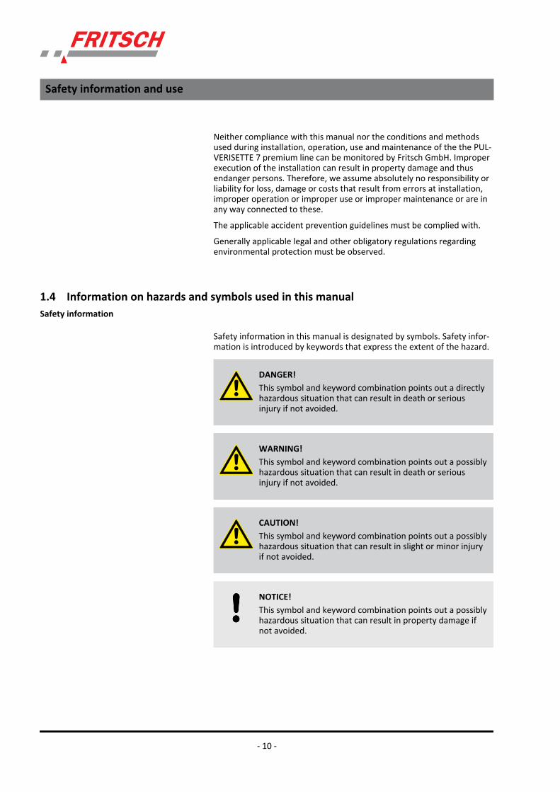
Safety information in this manual is designated by symbols. Safety infor-mation is introduced by keywords that express the extent of the hazard.
DANGER!This symbol and keyword combination points out a directlyhazardous situation that can result in death or seriousinjury if not avoided.
WARNING!This symbol and keyword combination points out a possiblyhazardous situation that can result in death or seriousinjury if not avoided.
CAUTION!This symbol and keyword combination points out a possiblyhazardous situation that can result in slight or minor injuryif not avoided.
NOTICE!This symbol and keyword combination points out a possiblyhazardous situation that can result in property damage ifnot avoided.
Safety information
Safety information and use
- 10 -

ENVIRONMENT!This symbol and keyword combination points out a possiblyhazardous situation that can result in environmentaldamage if not avoided.
To call attention to specific hazards, the following symbols are used inthe safety information:
DANGER!This symbol and keyword combination points out a directlyhazardous situation due to electrical current. Ignoring infor-mation with this designation will result in serious or fatalinjury.
DANGER!This symbol and keyword combination designates contentsand instructions for proper use of the machine in explosiveareas or with explosive substances. Ignoring informationwith this designation will result in serious or fatal injury.
DANGER!This symbol and keyword combination designates contentsand instructions for proper use of the machine with com-bustible substances. Ignoring information with this designa-tion will result in serious or fatal injury.
WARNING!This symbol and keyword combination points out a directlyhazardous situation due to movable parts. Ignoring infor-mation with this designation can result in hand injuries.
WARNING!This symbol and keyword combination points out a directlyhazardous situation due to hot surfaces. Ignoring informa-tion with this designation can result in serious burn injuriesdue to skin contact with hot surfaces.
Special safety information
Safety information and use
- 11 -

Safety information can refer to specific, individual procedure instruc-tions. Such safety information is embedded in the procedure instructionsso that the text can be read without interruption as the procedure isbeing carried out. The keywords described above are used.
Example:
1. Loosen screw.
2.CAUTION!Risk of entrapment at the lid.
Close the lid carefully.
3. Tighten screw.
This symbol emphasises useful tips and recommendationsas wells as information for efficient operation without mal‐function.
To emphasise procedure instructions, results, lists, references and otherelements, the following designations are used in this manual:
Designation Explanation
1., 2., 3. ...
Step-by-step procedure instructions
ð Results of steps in the procedure
References to sections in this manual and rele-vant documentation
Lists without a specific order
[Button] Operating elements (e.g. push button, switch),display elements (e.g. signal lamps)
‘Display’ Screen elements (e.g. buttons, function keyassignment)
1.5 Information on hazards at the deviceThere is a laser radiation hazard warning on the back of the device.
It is explained below.
Safety information in the procedureinstructions
Tips and recommendations
Further designations
Safety information and use
- 12 -

Do not remove the information and warning signs.
Caution! Hot surface
Caution! Crushing hazard
1.6 Device safety informationn Only use genuine accessories and genuine spare parts. Failure to
observe this instruction can compromise the safety of the machine.n Accident-proof conduct is to be strictly followed during all work.
Safety information and use
- 13 -

DANGER!Explosion hazard!– Wear safety goggles. The high temperature or chemical
reactions during the grinding process may result inoverpressure in the grinding bowl. Splashing hazard!Explosion hazard! Do not fail to observe Ä Chapter 5.1‘Safety information’ on page 27 and Ä Chapter 5.8.2‘Safety measures against an excessively high pressure’on page 40.
– Never use brute force to open the grinding bowl. Openthe grinding bowl only if you are sure that the internalpressure has been released completely. Observe theopening instructions in Ä Chapter 5.9.2 ‘Opening thegrinding bowl after a grinding operation’ on page 41and Ä Chapter 5.8.2 ‘Safety measures against anexcessively high pressure’ on page 40.
– The device may only be operated indoors. The sur-rounding air must not contain any electrically conduc-tive dust.
– When grinding oxidisable substances (e.g. metal orcoal), there is a risk of spontaneous combustion (dustexplosion) if the proportion of fine particles exceeds acertain percentage. Chemical reactions are also pos-sible during wet grinding. When grinding these kinds ofsubstances, special safety measures (e.g. wet grinding)must be taken and the work must be supervised by aspecialist.
– The device is not explosion-protected and is not suit-able for grinding explosive materials.
DANGER!– Do not reuse damaged accessories.– If the planetary micro mill or its components are dam-
aged or if its operation is not as described in the oper-ating manual, the device may not be put into service. Insuch a case, consult your Fritsch GmbH representativeor distributor.
WARNING!The maximum accepted concentration (MAC) levels of thevalid safety regulations must be observed. If necessary,ventilation must be provided or the machine must be oper-ated under an extractor hood.
Safety information and use
- 14 -

CAUTION!– Wear hearing protection! Above a sound level of
90dB(A)– Wear safety gloves! The grinding bowls may get very
hot. See Ä Chapter 1.8 ‘Hazardous points’ on page 16,Ä Chapter 5.8.1 ‘The effect of high temperature’on page 39 and Ä Chapter 5.12.10 ‘Cooling thegrinding bowl’ on page 58.
– Do not grind with the device for several hours in suc-cession without cooling phases. Risk of overheating!
– The device may not be run without supervision. In cer-tain operating states, the vibrations may result in ashifting effect on the surface.
n Do not remove the information signs.n Unauthorised alteration of the device will void Fritsch's declaration
of conformity to European directives and void the guarantee.n If, after reading the operating manual, there are still questions or
problems, please do not hesitate to contact our specialists.
1.7 Protective equipment
Protective equipment is to be used as intended and may notbe disabled or removed.
All protective equipment is to be regularly checked forintegrity and proper functioning.
DANGER!– The valves on the grinding bowls may not be repaired.
n Each time before using the planetary micro mill, check that the pro-tective equipment is not damaged or contaminated (seeÄ Chapter 1.8 ‘Hazardous points’ on page 16, Ä Chapter 1.9 ‘Elec‐trical safety’ on page 17 and Ä Chapter 5.1 ‘Safety information’on page 27).
n Do not make any changes to the protective equipment, apart fromthe maintenance tasks listed in the operating manual.
n The device's grinding chamber cover can only be opened and closedby a motor and therefore not without a connection to the powersupply. See Ä Chapter 1.9.2 ‘Protection against restart’ on page 17.
n It can only be opened when the mill comes to a stop.
Safety information and use
- 15 -
n The grinding chamber cover must always be closed during grinding.n When the grinding chamber cover is open, the mill's mechanical unit
is locked mechanically to prevent it from starting.
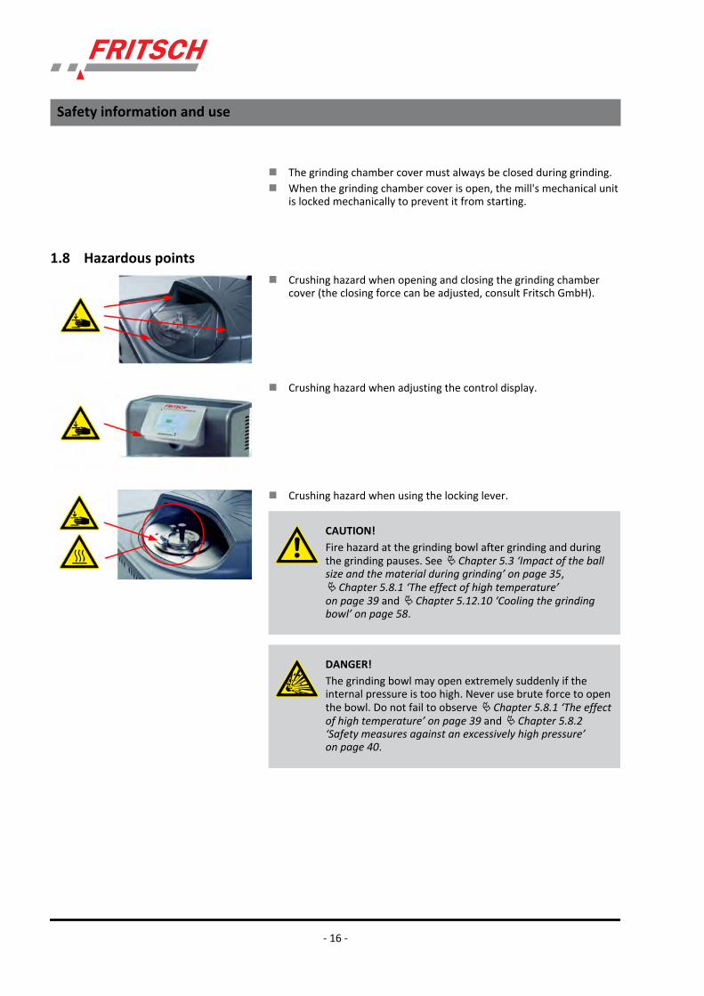
1.8 Hazardous pointsn Crushing hazard when opening and closing the grinding chamber
cover (the closing force can be adjusted, consult Fritsch GmbH).
n Crushing hazard when adjusting the control display.
n Crushing hazard when using the locking lever.
CAUTION!Fire hazard at the grinding bowl after grinding and duringthe grinding pauses. See Ä Chapter 5.3 ‘Impact of the ballsize and the material during grinding’ on page 35,Ä Chapter 5.8.1 ‘The effect of high temperature’on page 39 and Ä Chapter 5.12.10 ‘Cooling the grindingbowl’ on page 58.
DANGER!The grinding bowl may open extremely suddenly if theinternal pressure is too high. Never use brute force to openthe bowl. Do not fail to observe Ä Chapter 5.8.1 ‘The effectof high temperature’ on page 39 and Ä Chapter 5.8.2‘Safety measures against an excessively high pressure’on page 40.
Safety information and use
- 16 -

1.9 Electrical safety1.9.1 General information
n The main switch separates the device from the power supply withtwo poles.
n Turn off the main switch if the planetary micro mill is "out of service"for prolonged periods (e.g. overnight).
1.9.2 Protection against restartIn the case of a power failure during operation or after turning thedevice off at the main switch, the grinding chamber cover is locked.When the power supply is restored, the grinding chamber is not openeduntil the software detects that the drive is stationary. For safety reasons,however, the planetary micro mill does not restart.
1.9.3 Overload protectionn In the event of an overload, the device reduces the speed in a con-
trolled manner. This special operating state is indicated on the dis-play.
n The device shuts down if the drive motor becomes too hot.n The device shuts down if the drive is blocked.
1.9.4 Imbalance detectionThe device shuts down if there is excessive imbalance. See Ä Chapter 5‘Using the device’ on page 27.
Safety information and use
- 17 -

2 Technical data2.1 Dimensions
360 mm x 400 mm x 580 mm
(height x width x depth)
2.2 WeightNet: approx. 44 kg
Gross: approx. 61 kg
2.3 Operating noiseThe sound level is approx. 74 dB (A). This value fluctuates significantly,depending on the speed and material to be ground and on the type ofgrinding bowl and grinding balls.
The device is rated with IP 20.
2.4 VoltageThe device can be operated in two voltage ranges:
n Wide range input 100-240 V ± 10 %.
Transient overvoltage according to overvoltage category II permitted.
If the device is to be operated with two different voltages,e.g. 115 V or 230 V, it must be disconnected from the powersupply at least 60 seconds before switching over thevoltage.
2.5 Current consumptionThe maximum current consumption is approx. 10 A (115 V)
or 5 A (230 V).
2.6 Power consumptionThe maximum power consumption is approx. 1100 W.
Technical data
- 18 -

2.7 Electrical fusesn Fuses on the back of device: 2x10 A T
2.8 Materialn Maximum feed amount in the case of hard material approx. 5 mmn Maximum feed amount 2 x 35 ml
2.9 Final finenessn Dry grinding up to d50 < 20 µm (depending on the material)n Wet grinding up to d50 < 0.1 µm (depending on the material)
Technical data
- 19 -

3 Installation3.1 Transport
The device is delivered on a transport pallet with a wooden cover. Werecommend using a forklift or pallet truck for transporting the packeddevice.
DANGER!Do not step under the transport pallet during transport.
WARNING!Improper lifting can lead to personal injury or propertydamage. The machine is only to be lifted with suitableequipment and by qualified personnel.
The guarantee excludes all claims for damage due to improper transport.
3.2 Unpackingn Open the straps of the packaging.n Remove the lid from the crate or open the crate upwards.n Remove the accessory cardboard pieces and additional padding.n Lift the upper part of the packaging off the transport pallet.n The device can now be lifted off the pallet and out of the foam pad-
ding.
CAUTION!Crushing hazard!Always lift with 2 persons.
Hold the bottom edge of the housing when lifting.
n Compare the contents of the delivery with your order.
Installation
- 20 -
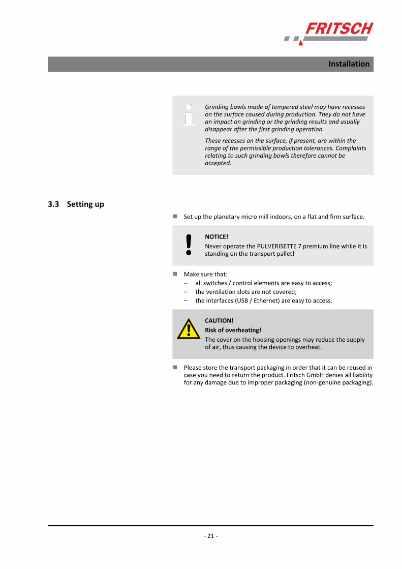
Grinding bowls made of tempered steel may have recesseson the surface caused during production. They do not havean impact on grinding or the grinding results and usuallydisappear after the first grinding operation.
These recesses on the surface, if present, are within therange of the permissible production tolerances. Complaintsrelating to such grinding bowls therefore cannot beaccepted.
3.3 Setting upn Set up the planetary micro mill indoors, on a flat and firm surface.
NOTICE!Never operate the PULVERISETTE 7 premium line while it isstanding on the transport pallet!
n Make sure that:– all switches / control elements are easy to access;– the ventilation slots are not covered;– the interfaces (USB / Ethernet) are easy to access.
CAUTION!Risk of overheating!The cover on the housing openings may reduce the supplyof air, thus causing the device to overheat.
n Please store the transport packaging in order that it can be reused incase you need to return the product. Fritsch GmbH denies all liabilityfor any damage due to improper packaging (non-genuine packaging).
Installation
- 21 -

3.4 Ambient conditions
WARNING!Mains voltage!– The device may only be operated indoors.– The surrounding air may not carry any electrically con-
ductive dust.– Maximum relative humidity 80% for temperatures up
to 31°C, linearly decreasing down to 50% relativehumidity at 40°C.
n The room temperature has to stay between 5 - 40°C.n Altitudes up to 2000 mn Degree of pollution 2 according to IEC 664.
3.5 Electrical connection
DANGER!Provide short-circuit protection!Risk of damage due to short-circuits.
– Make sure that the socket is connected to a mains lineprotected with a residual current circuit breaker.
Before establishing the connection, compare the voltage and currentvalues stated on the type plate with the values of the power supplysystem to be used.
DANGER!Mains voltage!Changes to the connection line may only be made by aqualified person.
CAUTION!Ignoring the values on the type plate may result in damageto the electrical and mechanical components.
Installation
- 22 -

NOTICE!Fritsch mills are speed controlled. The devices are equippedfor this with frequency converters. In order to comply withthe EMC directive, many measures must be taken to pre-vent operational transient emissions.
The possible leakage currents resulting from filtering meas-ures can trigger a conventional residual current circuitbreaker in the mains line. This is no defect!
To prevent this, special residual current circuit breakers,which are adapted for operation with frequency converters,are commercially available.
Operation without a residual current switch is possible, butmust be done in accordance with the relevant regulations.
Installation
- 23 -

4 Initial start-upSwitch on the device only after all work as described in Ä Chapter 3‘Installation’ on page 20 has been carried out.
4.1 Switching on1. Connect the device to the power supply using the cable provided
(device cable with IEC 320/C13 plug).
2. Gerät am Hauptschalter einschalten.
3. The display lights up.
4.2 Function check1. Grinding station 1 is moved into the loading position.
2. The grinding chamber cover opens.
3. Check if grinding station 1 is empty (no bowl inserted).
4. Press BUTTON "2" on the display.
5. Grinding station 2 is moved into the loading position.
6. Check if grinding station 2 is empty.
7. Press the "<" button for confirmation and to access the mainmenu.
8. Press the "Menu" button.
Initial start-up
- 24 -

9. You can make various settings in the next menu. Select the"Parameters" menu item.
10. A sub-menu appears in which you can enter the speed using theinput keys. Set the speed to 100.
11. Press the "<" button to save your entry and return to the mainmenu.
12. Press the "Start" button to close the grinding chamber cover andstart the safety check.
13. Various sensors check the bowls and the closing mechanism. Thatwill take a few moments.
Initial start-up
- 25 -

14. The sensors detect that the grinding bowls are not present.
15. Press the ">" button to open the grinding chamber cover andgrinding station 1 is moved into the loading position.
16. The device functions are OK.
4.3 Switching offIf the device is put out of service for a lengthy period, close the grindingchamber cover using the "Close" button and turn the device off at themain switch.
Initial start-up
- 26 -

5 Using the device5.1 Safety information
DANGER!The PULVERISETTE 7 premium line planetary mill fromFritsch enables speeds of up to 1100 rpm. The applicationof high energy may result in very high temperatures andhigh pressures in the grinding bowl.
Failure to observe the following safety instructions couldresult in the explosion of grinding bowls and parts flyingaround, causing injuries and damage to the building ordevice.
We cannot accept any liability for the occurrence and con-sequences of injuries or damage to the building or deviceresulting from a reaction of the sample material in thegrinding bowl that cannot be anticipated or controlled.
Bear in mind that it is essential that test grinding operationswith unknown parameters are always carried out in a saferoom that reliably prevents damage by exploding grindingelements.
WARNING!Make sure before starting the machine that the grindingbowls have been tensioned correctly and that there are noloose parts inside the device. There is a risk of loosegrinding bowls or parts being flung out. Failure to observethis will void the guarantee and release us from liability forany resulting damage to the device or personal injury.
NOTICE!During grinding, the temperatures in the grinding bowl mayget very high.
In encased grinding bowls, the inserts are glued into thecasing with a two-component construction adhesive.
The adhesive is resistant to temperatures up to approx. 140°C. Above 140 °C, the adhesive will liquefy and accumulatebelow the insert in the casing. When the adhesive coolsdown, it solidifies and pushes the casing up. That can causeirreparable damage to the insert. The grinding bowl willdefinitely be rendered unusable.
Above temperatures of 200 °C, the adhesive will bedestroyed. The same applies for encased grinding bowl lids.
Using the device
- 27 -
NOTICE!The planetary drive is provided by the main disc via atoothed belt drive. Constant high loads stress the toothedbelt severely, and may even damage it. High loads may be:heavy loads, high speeds, high temperatures, long oper-ating times or combinations of these.
NOTICE!The grinding duration in the reversing mode must notexceed 5 minutes. A longer grinding duration in thereversing mode may damage the PULVERISETTE 7 premiumline.
NOTICE!If the permissible maximum temperature in the bowl isexceeded during grinding, then the device must not beswitched off with the lid closed. That could lead to heataccumulation in the machine, which could cause damage tothe device.
Provide sufficient cooling by letting the mill continue to runat a speed of 100 rpm for approx. 20 - 30 min. or by shut-ting off the mill with the lid open.
5.1.1 General informationThe grinding bowls have been tested and approved for a static internalpressure of up to 20 bar.
If the pressure increases gradually, safety elements in the lid prevent thebuild-up of an unacceptable overpressure.
Fast and dynamic pressure surges (e.g. an explosion or very fast chemicalreactions, etc.) up to 30 bar will not cause any damage. A higher pres-sure will result in irreparable damage to the grinding bowl and possiblyalso damage the machine.
In such a case, the grinding bowls and the machine are not covered bythe Fritsch guarantee.
To clean the grinding bowl and its components, follow the operatinginstructions precisely (Ä Chapter 8 ‘Cleaning’ on page 101).
Using the device
- 28 -

5.1.2 Overpressure relief of the grinding bowlsThe grinding bowl seals have a sealing effect but are also for overpres-sure relief. If the pressure increases gradually during grinding, the specialseals open at a certain pressure and release the overpressure in adefined manner.
DANGER!This overpressure release does not work in the event ofsudden pressure surges (e.g. explosions).
A half-round notch with a diameter of 2 mm is punched onto the outerdiameter of the flat seal. The grinding bowl's pressure release works withflat seals made of fluororubber above a static internal grinding bowlpressure of about 10 bar. Flat seals made of silicone open above a staticinternal grinding bowl pressure of about 18 bar.
DANGER!If flat seals are used without this defined notch, very highpressures will develop in the grinding bowl that could causeit to burst (resulting in damage and injuries).
The application of high energy during grinding results in high tempera-tures in the grinding bowl. An 80 ml grinding bowl filled with 60 ml waterresults in the development of the following pressures and temperatures:
Temperature of grinding bowlwall [°C]
Pressure in the grinding bowl[bar]
101 1
109 2
127 4
141 6
152 8
159 10
166 12
171 14
177 17
180 19
183 21
If water is used as an additive, the overpressure release with fluoror-ubber flat seals is triggered at 159 °C, and with silicone flat seals at 180°C an. Any effects by the ground material are not taken into account.
Using the device
- 29 -

Be extremely careful if solvents are used. 60 ml isopropanol in an 80 mlgrinding bowl results in the development of the following pressure andtemperature:
Temperature of grinding bowlwall [°C]
Pressure in the grinding bowl[bar]
50 1
73 2
86 5
109 8
124 10.5
132 13
139 14
148 19
149 20
The overpressure limit for fluororubber flat seals is reached at 120 °Cand for silicone seals at 149 °C.
Here is an example of the pressure and temperature developmentduring an actual grinding operation:
Grinding balls: 120 g 0.4-0.7 mm ZrO2
Grinding bowl: 80 ml ZrO2
Material to be ground: 10 g aluminium oxide with feed size d50=20 µm
Addition: 30 ml water
Speed: 1100 rpm
Time [min] Bowl 1 [°C] Bowl 2 [°C]
10 124 119
15 140 136
Other configurations or material to be ground may result in high temper-atures being reached much sooner.
Because the gases and solids are mixed completely in thegrinding bowl, pure gas is never discharged. Material to beground is also discharged. To clean the mills, seeÄ Chapter 8 ‘Cleaning’ on page 101.
Using the device
- 30 -

5.1.3 Grinding bowl lidThe grinding bowl lids seal the grinding bowl gastight after manual pre-tensioning (see also Ä Chapter 5.8.2 ‘Safety measures against an exces‐sively high pressure’ on page 40). The locking hooks are designed towithstand an internal grinding bowl pressure of up to 40 bar.
Because the overpressure relief does not work in the case of suddenpressure surges, we would like to warn you explicitly that in the event ofan explosion in the grinding bowl, the hooks could be torn off.
DANGER!Danger to life!An explosion in the grinding bowl may cause severe injuriesand damage to the device.
In the context of our product monitoring, we would like to inform youabout the following damage cases that have occurred:
n During dry grinding of a light alloy/resin mixture, there was a severeexplosion of the grinding bowl after 64 cycles (5 min. grinding + 10min. pause; 800 rpm) that completely destroyed the device.
n During wet grinding of silicone powder in DEGBE (solvent), there wasan explosion in the grinding bowl exploded after 11 cycles (10 min.grinding + 30 min. pause) that ripped off the locking hooks of thegrinding bowl lid. The grinding bowl lid caused irreparable damageto the mill hood and the safety blocking mechanism stopped themill.
n During dry grinding of a silicon compound, in grinding conditions notknown to us and not disclosed by the customer, there was an explo-sion of the grinding bowl that ripped the locking hooks off thegrinding bowl lid.
5.2 Choice of grinding bowls and grinding balls
CAUTION!If the grinding elements used are not genuine accessories,we assume no guarantee and exclude all liability fordamage to the device or for personal injury.
Using the device
- 31 -

CAUTION!The grinding element is subject to normal wear during use.Before every grinding operation, check the wall thickness ofthe grinding bowls. In the event of severe wear, replace thegrinding bowl. If this is not done, the prevailing high centri-fugal forces during grinding may cause the grinding balls topenetrate the bowl's wall and damage the mill. Failure toobserve this will render void the guarantee and release usfrom liability for any resulting damage to the device or per-sonal injury.
The hardness and density (specific weight) of the grinding bowl andgrinding balls used must be greater than that of the material used, toprevent excessive wear by abrasion.
Material(bowl and balls)
Main components ofthe material
Density in g/cm3
High density meanshigh impact energy!
Abrasion resistance Use for grindingstock
Agate (99.9% SiO2) 2.65 Good Soft to medium-hardsamples
Silicon nitride (90% Si3N4) 3.25 Extremely good Abrasive samples,metal-free grinding
Sintered corundum (99.7% Al2O3) 3.9 Fairly good Medium-hard,fibrous samples
Zirconium oxide (96.2% ZrO2) 5.7 Very good Fibrous, abrasivesamples
Stainless steel Bowl:
(17-19% Cr + 8-10%Ni)
Balls:
(12.5-14.5% Cr + 1%Ni)
7.8 Fairly good Medium-hard, brittlesamples
Tempered steel Bowl: (11-12% Cr)
Balls: (1.0-1.65% Cr)
7.9 Good Hard, brittle samples
Tungsten carbide (93% WC+6% Co) 14.9 Very good Hard, abrasive sam-ples
The grinding bowls and grinding balls made of zirconium oxide areresistant to acids - apart from hydrofluoric acid.
Normally choose a grinding bowl and grinding balls that are made of thesame material.
Using the device
- 32 -

Exception: Tungsten carbide balls (<20 mm) may be temporarily (a fewminutes) combined with grinding bowls made of tempered steel.
5.2.1 Useful capacity of the grinding bowls
Grinding bowl 20 ml 45 ml 80 ml
Useful capacity(material to beground)
1-9 ml 3-20 ml 10-30 ml
5.2.2 Size of the grinding balls
Type of feed material Suitable ball diameter
Hard samples with a maximum feed size of 5 mm 15 mm / 20 mm
Average feed size of 0.5 – 1 mm 15 mm / 10 mm
Fine material 0.1 – 0.5 mm 10 mm / 5 mm
Very fine material < 0.1 mm 3 mm and smaller
Homogenisation of dry or liquid samples 10 mm / 5 mm
NOTICE!It is not advisable to mix balls of different diameters. (Ifballs with different diameters are used, increased wear tothe balls is to be expected.)
Using the device
- 33 -

5.2.3 Number of balls per grinding bowl (independent of the material quantity)A higher number of balls will reduce the grinding duration and thegrinding results will be within a smaller grain size range.
The number of balls should be complied with to avoid unnecessary wear.
Ball diameter (mm) Grinding bowlvolume (ml)
20 45 80
20 Number of balls (St) - - 5
15 Number of balls (St) - 7 10
10 Number of balls (St) 10 18 25-30
5 Number of balls (St) 80 180 250
Ball with a diameter of 3 mm and smaller
Material Grinding bowlvolume (ml)
20 45 80
Zirconium oxide Amount of balls(grams)
30 70 100
Tempered steel Amount of balls(grams)
40 90 150
Tungsten carbide Amount of balls(grams)
80 200 300
Using the device
- 34 -

5.2.4 Calculated weight of a ball
Ball diameter in mm 5 10 15 20
Material Densityin g/cm3
Calculated weight of a ball in g
Agate 2,65 0,17 1,39 4,68 11,1
Silicon nitride 3,25 0,20 1,16 5,48 12,99
Sinteredcorundum
3,9 0,25 1,99 6,72 15,92
Zirconium oxide 5,7 0,37 2,98 10,07 23,88
Stainless steel 7,8 0,51 4,08 13,78 32,67
Tempered steel 7,9 0,52 4,14 13,96 33,09
Tungsten car-bide
14,9 0,96 7,40 25,98 61,58
To determine the weight of the required balls, the "calculated weight ofa ball" is multiplied with the "amount" of balls required.
Example: A 45 ml agate bowl is to be filled with 185 agate balls with adiameter of 5 mm.
Calculation: 0.17 g x 185 St = 31.45 g
31.45 g grinding balls can be weighed and inserted in the grinding bowl,thus avoiding the time required for counting the balls.
5.3 Impact of the ball size and the material during grindingLarge balls with a diameter of 10 mm – 20 mm will result in highmechanical system stress. The combination of the heavy weight of theballs and high acceleration result in high mechanical stress → impacteffect.
The higher the density of the material to be ground, thehigher the mechanical stress is.
The highest mechanical stress is achieved with balls made of tungstencarbide with a diameter of 20mm.
If large agate balls are used, they could destroy themselves and thegrinding bowls.
That is also the case with sintered corundum and silicon nitride balls.
Balls with a diameter of 5 mm and less result in high thermal systemstress.
Using the device
- 35 -

The large surface of many small balls results in high thermal stress due tothe friction effect. It can already be measured after 5 minutes of grindingabove 100 °C by a surface sensor on the surface of the lid. Inside thegrinding bowl, the temperature is then much higher.
The adhesive used is permanently resistant to temperaturesof up to 140 °C. If the external temperature does not exceed100 °C, the adhesive will hold.
5.4 Filling quantities of grinding bowls
Grinding bowl Min. sample quantity Max. sample quantity
20 ml 1 ml 9 ml
45 ml 3 ml 20 ml
80 ml 10 ml 30 ml
CAUTION!For wet grinding with large balls with a diameter of >10mm, at least half the maximum sample quantity must beinserted. If the suspension is highly fluid, the balls will nothave any resistance and the balls and the grinding bowlcould be damaged. The result is the same as if no materialto be ground were filled. The same applies to dry grindingwith less than the minimum sample quantity.
NOTICE!If the minimum filling quantity is fallen short of, increasedwear due to abrasion is to be expected. This can causeirreparable damage to the mill components.
5.5 Filling the grinding bowlDo not fail to comply with the following sequence:
1. Place the grinding balls in the empty bowl.
2. Fill material to be ground over the balls.
Using the device
- 36 -

CAUTION!Never operate the device without material to be ground,otherwise the grinding balls and grinding bowl will be dam-aged.
5.6 Factors with an impact on grinding5.6.1 Running time (grinding duration)
A longer grinding duration will increase the percentage of fine material.To reduce the running time, you can use a grinding bowl and grindingballs with a higher density, and thus a higher impact energy.
5.6.2 SpeedHigher speeds shorten the grinding time and increase the share of fineparticles.
5.6.3 Reverse mode
NOTICE!The grinding duration in the reversing mode must notexceed 5 minutes. A longer grinding duration in thereversing mode may damage the PULVERISETTE 7 premiumline.
Useful for mechanical alloying.
Improvement of the homogeneity of the sample.
The grinding duration of a grinding cycle in reversing mode must notexceed 5 minutes. The overall duration is determined by the number ofcycles.
Overall grinding duration = time x cycles
5.6.4 Number and size of the ballsPre-grind course, hard material with large balls:
reduced percentage of fine material!
Many small balls increase the percentage of fine material duringextended running time.
Using the device
- 37 -

5.6.5 Weight of the balls (type of material)A higher mass (specific weight) of the grinding balls accelerates grinding.(see table in Ä Chapter 5.2 ‘Choice of grinding bowls and grinding balls’on page 31).
5.7 Dry grindingBelow a particle size of approx. 20 µm, the surface forces prevail and thematerial to be ground starts to "stick".
Additional dry comminution can be achieved by adding surface-activesubstances to the material to be ground.
Examples (maximum amount to be added in mass%)
n Stearic acid 2-3%n Aerosil (fine-particle silicic acid) 0.5-2%n Quartz sand ~ 2%n Glass powder ~ 2%
5.8 Wet grinding (grinding in a suspension)
DANGER!Explosion hazard! Ignition hazard!The device is not explosion-protected. If flammable liquidsare used, make sure that the heat developing in thegrinding bowl does not reach the solvent's boiling point.Program appropriate cooling phases. If the vapour pressureis too high, vapours may escape and ignite.
If it can be avoided, we recommend using non-flammableliquids or liquids with a high boiling point. The boiling pointshould be above 80 °C and above 100 °C for a long grindingduration.
During the transition to grinding in suspension, you can add a liquid aux-iliary agent with high boiling point and low vapour pressure, e.g. water,white spirits (boiling point 100 - 140°C), or alcohols with a high boilingpoint (e.g. isopropanol)
We recommend that you only use so much liquid that the suspensionhas the same consistency as motor oil. With this viscosity the best resultscan be achieved in most cases.
Using the device
- 38 -

5.8.1 The effect of high temperature
DANGER!During wet grinding in the grinding bowls, the high internaltemperature, the increase in size of the surface of the parti-cles due to crushing and any chemical reactions in the bowlmay result in the development of a very high pressure.
This pressure can get so high that the hooks that hold thelid on the bowl crack, resulting in the lid "flying off". Duringgrinding tests, chemical reactions of steel parts (temperedsteel and stainless steel) and tungsten carbide parts withwater suspension were determined. After a grinding periodof 20 minutes, the increase in pressure could tear off thelocking hooks. The grinding bowl temperature may be rela-tively low.
DANGER!Explosion hazard! Ignition hazard! Burn hazard!In the event of a longer grinding duration, apply coolingpauses to reduce the internal pressure. For certain materialto be ground, it may also be necessary to release the pres-sure after the cooling phase, otherwise it could be retainedin the bowl in spite of cooling. That is in particular also thecase in the event of a chemical reaction in the grindingbowl. See Ä Chapter 5.3 ‘Impact of the ball size and thematerial during grinding’ on page 35, Ä Chapter 5.8.2‘Safety measures against an excessively high pressure’on page 40 and Ä Chapter 5.12.10 ‘Cooling the grindingbowl’ on page 58.
NOTICE!If the permissible maximum temperature in the bowl isexceeded during grinding, then the device must not beswitched off with the lid closed. That could lead to heataccumulation in the machine, which could cause damage tothe device.
Provide sufficient cooling by letting the mill continue to runat a speed of 100 rpm for approx. 20 - 30 min. or by shut-ting off the mill with the lid open.
The bowl may get stuck on the holder if the bowl temperature gets toohigh. In such a case, wait until the bowl has cooled down sufficiently inorder that it is released by the holder.
Using the device
- 39 -

5.8.2 Safety measures against an excessively high pressureSafety measures against an excessively high pressure
1 Recess
To prevent damage to the grinding bowls and the device, the flat sealhas a small recess on its external diameter. The pressure may bereleased at this point if the insert is lifted by the internal pressure in thebowl. That is the case with an internal pressure of about 20 bar.
Use genuine seals only.
WARNING!Never use brute force to open the bowl
5.9 Handling the grinding bowl5.9.1 Design
1 Compl. bowl2 Compl. lid3 Flat seal4 Locking hook5 Compl. handle6 Valve plug7 Press-on sleeve8 Actuating pin9 Lid insert
Using the device
- 40 -

5.9.2 Opening the grinding bowl after a grinding operation1. Allow the bowl (1) to cool down.
2. Release the pressure by turning the press-on sleeve (7) to open it.
NOTICE!After releasing the pressure via the press-on sleeve,this and the valve plugs (6) must be cleaned thor-oughly before further grinding processes. If this is notdone, the tightness may be reduced due to residualsample material.
After restarting and reaching the set speed, we rec-ommend securing the press-on sleeve (7) and handle(5) again.
3. Turn the handle (5) to open it.
4. If the lid insert (9) is sticking on the flat seal (3), apply a screw-driver to the actuating pin (8) to remove the lid insert (9) from theflat seal (3).
5. Open the lid (2).
Using the device
- 41 -
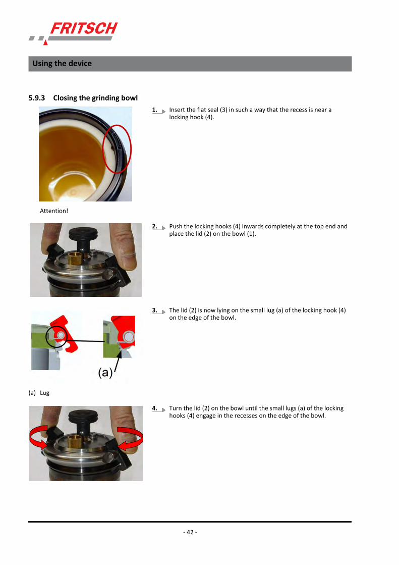
5.9.3 Closing the grinding bowl1. Insert the flat seal (3) in such a way that the recess is near a
locking hook (4).
2. Push the locking hooks (4) inwards completely at the top end andplace the lid (2) on the bowl (1).
3. The lid (2) is now lying on the small lug (a) of the locking hook (4)on the edge of the bowl.
4. Turn the lid (2) on the bowl until the small lugs (a) of the lockinghooks (4) engage in the recesses on the edge of the bowl.
Attention!
(a) Lug
Using the device
- 42 -

5. Release the locking hooks (4) and push them together at thebottom end until they engage and are exactly vertical.
6. Make sure that the locking hooks engage exactly in the middle ofthe recess. Only then can the bowl be closed properly and insertedin the device.
+ Make sure that the distances are the same.
7. Turn the handle (5) down firmly; the press-on sleeve (7) must bereleased for air to escape from the bowl.
8. Turn the press-on sleeve (7) down firmly.
NOTICE!Once the locking hooks are engaged, the lid may no longerbe turned against the bowl. The positions of the hooks andgrooves in the bowl below the hooks must match
Using the device
- 43 -

5.9.4 Inserting the grinding bowl in the grinding bowl holderCarry out the following checks before inserting the grinding bowls:
1. Are the grinding bowls clean on the outside? à remove anycoarse dirt.
2. Is the grinding bowl adapter clean on the inside? à remove anycoarse dirt.
3. Are the grinding bowls sealed correctly (see Ä Chapter 5 ‘Usingthe device’ on page 27).
Inserting the grinding bowls
1. Open the clamping bracket (10).
2. Hold the grinding bowl at the handle (5) and set it in the grindingbowl adapter.
3. Turn the grinding bowl until it can be felt to engage and drops afew millimetres into the grinding bowl adapter.
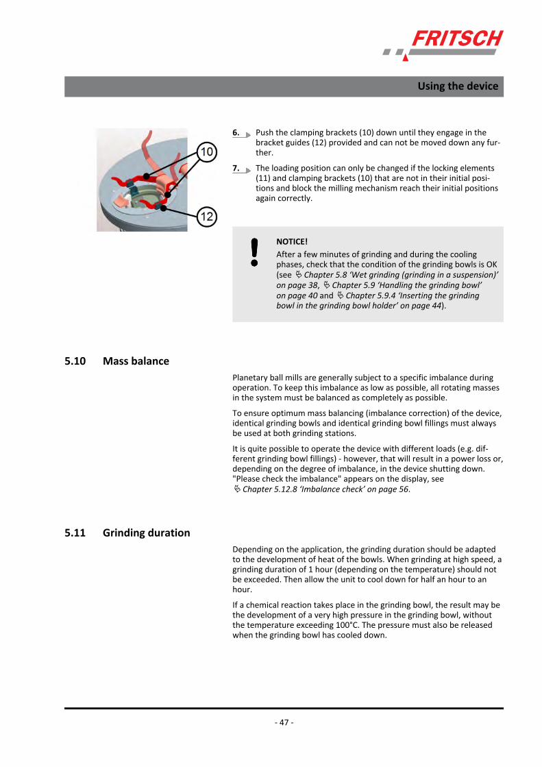
10 Clamping bracket11 Locking element12 Bracket guide
Using the device
- 44 -

4. Push the locking element (11) down on the bowl holder. à thegrinding bowl is lowered within the mounting device.
5. Apply vertical pressure to the grinding bowl handle (5) to lock thegrinding bowl in place in its adapter. The grinding bowl is lockedcorrectly if the locking element (11) on the mounting devicemoves back up into its initial position.
6. Push the clamping brackets (10) down until they engage in thebracket guides (12) provided and can not be moved down any fur-ther.
7. As long as the locking element (11) and the locking brackets (10)are not in their original positions, the rotation of the complete millmechanism is blocked.
5.9.5 Removing the grinding bowl1. Open the clamping bracket (10).
Using the device
- 45 -

2. Push the locking element (11) down on the bowl holder.
3. The grinding bowl is unlocked and moves up a few millimetres.
4. Now, the grinding bowl can be removed (upwards) from its holder.(Hold the grinding bowl preferably at the handle (5) provided forthis purpose).
5. When the grinding bowl is removed, the locking element (11)moves back into its initial position.
Using the device
- 46 -
6. Push the clamping brackets (10) down until they engage in thebracket guides (12) provided and can not be moved down any fur-ther.
7. The loading position can only be changed if the locking elements(11) and clamping brackets (10) that are not in their initial posi-tions and block the milling mechanism reach their initial positionsagain correctly.
NOTICE!After a few minutes of grinding and during the coolingphases, check that the condition of the grinding bowls is OK(see Ä Chapter 5.8 ‘Wet grinding (grinding in a suspension)’on page 38, Ä Chapter 5.9 ‘Handling the grinding bowl’on page 40 and Ä Chapter 5.9.4 ‘Inserting the grindingbowl in the grinding bowl holder’ on page 44).
5.10 Mass balancePlanetary ball mills are generally subject to a specific imbalance duringoperation. To keep this imbalance as low as possible, all rotating massesin the system must be balanced as completely as possible.
To ensure optimum mass balancing (imbalance correction) of the device,identical grinding bowls and identical grinding bowl fillings must alwaysbe used at both grinding stations.
It is quite possible to operate the device with different loads (e.g. dif-ferent grinding bowl fillings) - however, that will result in a power loss or,depending on the degree of imbalance, in the device shutting down."Please check the imbalance" appears on the display, seeÄ Chapter 5.12.8 ‘Imbalance check’ on page 56.
5.11 Grinding durationDepending on the application, the grinding duration should be adaptedto the development of heat of the bowls. When grinding at high speed, agrinding duration of 1 hour (depending on the temperature) should notbe exceeded. Then allow the unit to cool down for half an hour to anhour.
If a chemical reaction takes place in the grinding bowl, the result may bethe development of a very high pressure in the grinding bowl, withoutthe temperature exceeding 100°C. The pressure must also be releasedwhen the grinding bowl has cooled down.
Using the device
- 47 -
The PULVERISETTE 7 premium line is not suitable for grinding with steelor tungsten carbide grinding bowls in water suspensions. The applicationof extremely high energy results in abrasion wear in the nano range.That can result in chemical reactions that cannot be controlled.
To what extent the heating up of the material to be groundneeds to be observed naturally depends on the corre‐sponding sample in each individual case. Noteà a longerduration may also require a long pause time for coolingdown.
If bowls are removed during a grinding pause, check thatthe bowl is seated correctly before the device is switchedback on.
5.12 Conducting a grinding operation
DANGER!– Explosion hazard!– Ignition hazard!– Burn hazard!– Wear safety goggles.– Wear safety gloves.
The following needs to be observed when grinding materialfor which there is no experience with premium line:
Initially, a grinding duration of 5 minutes should be set and the tempera-ture measured on the actuating pin using a surface thermometer. If it isbelow 80 °C, grinding can be continued until a temperature of 90 °C isreached. At this temperature, it is advisable to apply a cooling pause ofabout 15-30 minutes. At the end of the cooling pause, open the knurledscrew to check if pressure has built up in the bowl. If there is no highpressure, the grinding and pause times can be programmed in such away that the temperature does not exceed 90 °C.
During the pause, the mill continues to run at low speed forbetter cooling. (From firmware V1.08 and higher)
Using the device
- 48 -

If prolonged blow-off noises and the discharge of source material sus-pension indicate a high internal pressure after cooling, take special carewhen you continue to grind. The pressure must always be released afterthe cooling pauses (at least for 30 minutes in order that the suspensioncan settle) to prevent it from getting too high. Sooner or later, theincrease in pressure will stop.
5.12.1 Program sequence after switching on1. Turn the device on at the main switch.
2. The display lights up.
3. During the start and initialisation phase, you can press the INFObutton to have information displayed with the contact address.Press the Next button to close this information again.
4. Grinding station 1 is moved into the loading position. The grindingchamber cover opens automatically.
5. Insert the grinding bowl (Ä Chapter 5.5 ‘Filling the grinding bowl’on page 36), loaded with the sample (Ä Chapter 5.9 ‘Handling thegrinding bowl’ on page 40) and closed correctly, in the grindingbowl holder (Ä Chapter 5.9.4 ‘Inserting the grinding bowl in thegrinding bowl holder’ on page 44).
Using the device
- 49 -

6. Grinding station 1 is moved into the loading position. The grindingchamber cover opens automatically.
7. Insert the grinding bowl (Ä Chapter 5.5 ‘Filling the grinding bowl’on page 36), loaded with the sample (Ä Chapter 5.9 ‘Handling thegrinding bowl’ on page 40) and closed correctly, in the grindingbowl holder (Ä Chapter 5.9.4 ‘Inserting the grinding bowl in thegrinding bowl holder’ on page 44).
8. You can press the Close button (c) to close the grinding chamber.
9. Press the Next button (b) to return to the main menu.
10. To enter the process parameters, either press the indication (d) ofthe data (touch function) or press the MENU button (e) → press thePARAMETER button (f) to open the parameter input screen.
11. The field coloured in black is active. When you start to enter anumber, the previous one is deleted, or press the C button todelete the current parameter. Maximum possible entries are:
Speed = 1100 rpm,
time = 999 min, pause = 99 min,
cycles = 99.
12. After entering the parameters, press the < button to return to themain menu.
Using the device
- 50 -

13. Press the Start button à the grinding chamber is closed and thesafety check starts.
14. Various sensors check the bowls and the closing mechanism of thedevice. That will take a few moments. The Stop button stops theprocess.
15. If the check is successful, this is confirmed and grinding is thenstarted without delay.
16. If the sensors detect insufficient safety, the starting procedure isinterrupted and the cause is displayed. Press the > button to openthe grinding chamber and move grinding station 1 into the loadingposition. When the error is corrected, grinding can be continued.
Using the device
- 51 -

5.12.2 Starting grinding at high speedIf the speed exceeds 600 rpm, the correct ball size must be selected.
CAUTION!If the wrong balls are selected, they will be destroyed bythe high grinding energy.
Depending on the choice of the ball size, the maximum speed is reduced.
A reduced speed is indicated briefly by a flashing target speed indicator.
The Stop button stops the grinding process.
Press the Info button to display some system information and the type ofgrinding elements.
Reference values for the speed limit
Ball diameter (mm) Speeds (rpm) foragate
Speeds (rpm) for allother materials
<5 1100 1100
5 900 100
10 750 850
>10 600 700
Using the device
- 52 -

5.12.3 OverloadIf the planetary micro mill is overloaded, the speed is reduced. Thereduced speed flashes on the display.
5.12.4 "Program" menu itemGrinding cycles can be programmed, saved and selected here.
1. Press the "Menu" button in the main menu.
2. Then press the "Program" button → A new window appears.
3. The "Current" column shows the current parameters of previousentries.
4. The "Program" column shows the data previously stored underbutton 1.
Using the device
- 53 -

5.12.5 Saving the current data1. First select the program section that is free or to be overwritten.
2. Then, press the Save button to save the current parameters to theselected program section.
3. After saving them successfully, the new parameters are now dis-played in the "Program" column.
5.12.6 Loading the program1. Select one of the programs 1..8, the various parameter records are
displayed in the Program column.
2. Press the "Load" button to transfer the program data record.
Using the device
- 54 -

3. Press the "<" button to return to the main menu. The program isdisabled by manual input e.g. of the speed (see Ä Chapter 5.12.1‘Program sequence after switching on’ on page 49).
5.12.7 Setting the time control1. Select Menu.
2. Select Clock.
3. Select the time base for the internal clock.
Using the device
- 55 -

4. Press the "<" button to confirm your entry
5. Enter the time offset. By entering a time offset, grinding is onlystarted after this delay in time. This function is displayed as activein the main menu.
6. Press the "<" button to confirm your entries
ð The time offset is reset to 0000 after grinding.
5.12.8 Imbalance checkThe distribution of different weights in both bowls will obviously result indifferent vibrations, also depending on the speed.
Using the device
- 56 -

To tolerate this imbalance within specific limits, you can set the shut-down threshold.
Touch the adjustment bar or move it back and forth by applying slightpressure.
Press the "<" button to confirm your entries
Small setting values make the measuring system more sen‐sitive, and high values make it less sensitive.
5.12.9 Switching off
NOTICE!If the permissible maximum temperature in the bowl isexceeded during grinding, then the device must not beswitched off with the lid closed. That could lead to heataccumulation in the machine, which could cause damage tothe device.
Provide sufficient cooling by letting the mill continue to runat a speed of 100 rpm for approx. 20 - 30 min. or by shut-ting off the mill with the lid open.
1. Press "STOP" on the display.
2. When the drive comes to a stop, grinding station 1 is moved intothe loading position and the grinding chamber cover opens auto-matically.
Using the device
- 57 -

3. If the device is put out of service for a lengthy period, close thegrinding chamber cover and turn the device off at the main switch.
5.12.10 Cooling the grinding bowlThe grinding bowls can be cooled
1. with the grinding chamber cover open and the fan running (thefan continues to run for 1 minute);
2. or by the programmed pause times with closed (locked) grindingchamber cover and the fan running.
Using the device
- 58 -

6 Accessories6.1 Standard gassing lid for grinding with inert gas
NOTICE!Our workers perform a water bath test on all gassing lids.The part to be tested is sealed, a pressure of 5.5 bar isapplied and it is immersed in a water bath. If there is a leak,bubbles will develop. The air bubbles that develop within aspecific interval are evaluated by the worker/tester.
Only gassing lids with a leak rate of <10-4 [mbar l/s] areapproved.
6.1.1 Scope of delivery
(1) Hexagon socket wrench, 13mm(2) 2 x flat seal 57.5x48x2mm, silicone, for grinding bowl
(1 x replacement)(3) Compl. gassing lid(4) 4 x flat seal 6.3x1.8x1mm, viton, for valves (replace-
ment)
(5) 2 x valve inserts (replacement)(6) Valve key for turning the valve inserts out of the
valve(7) Hose with adapter on valve
Accessories
- 59 -

6.1.2 Fitting the gassing lid on the grinding bowl1. Place the silicone flat seal (2) on the edge of the bowl insert.
2. The central handle (9) must be removed as illustrated.
3. Hold the lid at the hook. Push the hook up and place the lid on thebowl.
4. Turn the lid with the hooks pressed outwards on the bowl, untilthe lugs of the hooks engage in the recesses on the edge of thebowl fitting (Ä Chapter 5.9.3 ‘Closing the grinding bowl’on page 42).
(9) Gassing lid handle
Accessories
- 60 -

5. After releasing the hooks, they must be immersed completely inthe recesses on the outer diameter of the bowl fitting and beexactly vertical.
6. Push the central handle (9) down by hand until the resistanceincreases.
Accessories
- 61 -

7. Use the hexagon socket wrench (1) to tighten it with maximummanual force. The maximum manual force is equivalent to atorque of approx. 3.5-4Nm.
8. This is what the closed grinding bowl looks like.
6.1.3 Hose adapter for grinding bowl gassing1. Push the locking lever (11) of the connection on the hose inwards.
(11) Locking lever
Accessories
- 62 -

2. Push the hose connection onto the valve (8) and down onto theinner seal. At the same time, the valve is opened by an internal pinin the hose connection. When the locking lever is released, itengages on the valve thread.
3. For flushing, the second valve can be opened with a pen, e.g. thetip of a ballpoint pen.
NOTICE!The gas must be supplied very slowly to avoid any turbu-lence in the grinding bowl or of the material to be groundwhen it is inserted.
4. After gassing the sample, remove the hose (7) again. The grindingbowls are inserted and handled as shown in Ä Chapter 5 ‘Usingthe device’ on page 27.
6.1.4 Removing the gassing lid in individual steps1. Turn the central handle (9) and remove it by hand.
(8) Valve(9) Gassing lid handle(10) Actuating pin
Accessories
- 63 -

(10) Actuating pin
2. Unscrew the two actuating pins (10) with a broad slotted screw-driver (tightening torque approx. 4-5Nm = maximum manualforce).
3. Unscrew the two valves (8) using the socket wrench (1) (tighteningtorque approx. 3.5-4Nm = maximum manual force).
4. Remove the flat seals (4) under the valves. The flat seals aredeformed by the contact pressure.
(4) Flat seal
Accessories
- 64 -

(5) Valve insert
5. Turn the two valve inserts out of the valves using the valve key (6).(Tightening torque approx. 1.5-2Nm = average manual force). Thevalve is held in place using the socket wrench (1), and the valveinsert (5) is removed using the valve key (6).
NOTICE!Do not forget to insert the two valve flat seals (4).
6. The gassing lid is removed in the reverse order.
(4) Flat seal
Accessories
- 65 -

6.2 Gassing lid with stainless steel, swagelok hose couplings
NOTICE!Our workers perform a water bath test on all gassing lids.The part to be tested is sealed, a pressure of 5.5 bar isapplied and it is immersed in a water bath. If there is a leak,bubbles will develop. The air bubbles that develop within aspecific interval are evaluated by the worker/tester.
Only gassing lids with a leak rate of <10-4 [mbar l/s] areapproved.
6.2.1 Scope of delivery / lid design
1 Compl. gassing lid handle2 Compl. gassing lid fitting3 Gassing valve connecting plug4 Gassing valve quick-release coupling5 Sealing ring 8x12x1mm, vulcanised fibre
6 Flat seal7 Actuating pin8 Gassing lid insert9 Flat seal, 57.5x48x2, silicone10 Hexagon socket wrench size 13
Accessories
- 66 -

11 Single head wrench, size 11
6.2.2 Fitting the gassing lid on the grinding bowl1. Place the silicone flat seal (9) on the edge of the bowl insert.
2. Place the gassing lid insert (8) with the seal gassing valves (3 and 4)and actuating pins (7) on the flat seal (9) in the bowl.
3. Hold the lid (2) at the hooks. Push the hooks outwards and placethe lid (2) on the bowl above the gassing lid insert (8).
4. The central handle (1) must be removed as illustrated.
Accessories
- 67 -

5. Turn the lid (2) with the hooks pressed outwards on the bowl, untilthe lugs of the hooks engage in the recesses on the edge of thebowl fitting (Ä Chapter 5.9.3 ‘Closing the grinding bowl’on page 42). After releasing the hooks, they must be immersedcompletely in the recesses on the outer diameter of the bowl fit-ting and be exactly vertical.
6. Push the central handle (1) down by hand until the resistanceincreases. Use the hexagon socket wrench (10) to tighten it withmaximum manual force. The maximum manual force is equivalentto a torque of approx. 3.5-4Nm.
7. This is what the closed grinding bowl looks like.
Accessories
- 68 -
6.2.3 Hose adapter for grinding bowl gassing
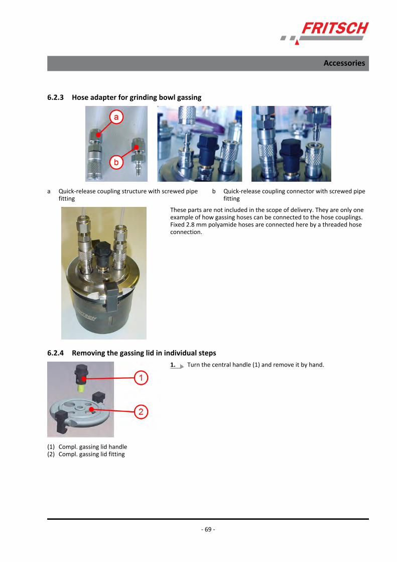
a Quick-release coupling structure with screwed pipefitting
b Quick-release coupling connector with screwed pipefitting
These parts are not included in the scope of delivery. They are only oneexample of how gassing hoses can be connected to the hose couplings.Fixed 2.8 mm polyamide hoses are connected here by a threaded hoseconnection.
6.2.4 Removing the gassing lid in individual steps1. Turn the central handle (1) and remove it by hand.
(1) Compl. gassing lid handle(2) Compl. gassing lid fitting
Accessories
- 69 -

2. Unscrew the two actuating pins (7) with a broad slotted screw-driver (tightening torque approx. 4-5Nm = maximum manualforce)
3. Unscrew the two valves (3 and 4) using the size 11 single-headwrench (11) (tightening torque approx. 3.5-4Nm = maximummanual force)
4. Remove the seals (5 and 6) from under the valves. The seals aredeformed by the contact pressure.
NOTICE!Do not forget to insert the two valve flat seals (5 and 6).
5. The gassing lid is fitted in the reverse order.
7 Actuating pin
4 Gassing valve quick-release coupling5 Sealing ring 8x12x1mm, vulcanised
fibre6 Flat seal8 Gassing lid insert
3 Gassing valve connecting plug5 Sealing ring 8x12x1mm, vulcanised
fibre6 Flat seal8 Gassing lid insert
Accessories
- 70 -

6.3 EASY GTM Gas Pressure and Temperature Measuring SystemThe EASY GTM gas pressure and temperature measuring system is usedto control the grinding process and for mechanical alloying.
NOTICE!If grinding balls with a diameter of 1 mm are used, there isa risk of the clearance holes of the lid getting clogged,which could falsify the pressure and temperature measure-ment. Grinding balls with a diameter of up to 0.8 mm orgrinding balls with a diameter of 1.2 mm or greater can beused without any problem.
6.3.1 Case contents and system design
1 2.6 Nm torque spanner + hexagonal bit2 2x battery, 1.5 V, AA3 EASY GTM system4 Flat sealing ring, 54x2, silicone foam5 O-ring, 21x2.56 Hexagon screwdriver, 3mm
7 Hexagon offset screwdriver, 2.5mm8 Measuring/transmission unit9 Lid10 Compl. bowl11 locking ring with 6 socket head screws
Accessories
- 71 -

6.3.2 Inserting / changing the batteryPrior to initial start-up, the battery (2) provided must be inserted in themeasuring/transmission unit (8) of the system.
When inserting it for the first time and during subsequent replacementof the battery, proceed as follows:
1. If not already done, switch off the radio system using the button(A). The LED (B) goes out.
2. Then release the six socket head screws (C) for closing the systemusing a hexagon screwdriver (7). The locking ring (11) with 6socket head screws can be removed now. (see Ä Chapter 6.3.11‘Cleaning the EASY GTM system’ on page 83)
3. Carefully lift the measuring/transmission unit (8) off the bowl (10).
4. If the lid (9) is on the unit, release it by hand and place it to theside. The lid normally remains on the bowl (10).
Accessories
- 72 -

5. Undo the two screws (D) of the battery compartment using a hex-agon offset screwdriver, size 2.5mm (6).
6. Lift off the battery compartment lid and place it to the side. Thebattery compartment can be seen.
NOTICE!Please note that the the battery (2) fits exactly in place andmay need to be pushed in using a certain amount of force.
The service life of the battery (2) depends on the frequencyof the radio protocols (see configuration) and essentially onthe temperature inside the grinding bowl.
Also pay attention to the battery's charge level. If the bat-tery's capacity falls below 10%, it should be replaced imme-diately.
7. Remove the old battery and insert the new battery (2). Batterytype: 1.5V / AA
When inserting the battery pay attention to thepolarity!
8. Close the battery compartment! Make sure the plug contacts arein the correct position!
Accessories
- 73 -

6.3.3 Configuration of transmitter ID and data transmission frequencyThe measuring/transmission unit (12) is equipped with four configura-tion switches for setting the transmitter ID and data transmission fre-quency.
The switches illustrated are all OFF (actuator cams set to OFF).
6.3.3.1 Adjustment options of the transmitter detection
Upon delivery, all switches are set OFF. This means as identification thatit is cup 1 and the transmission frequency is 1 second.
ID Switch 1 Switch 2
Transmitter no. 1 OFF OFF
Transmitter no. 2 ON OFF
Transmitter no. 3 OFF ON
Transmitter no. 4 ON ON
NOTICE!For the operation of two or more EASY GTM systems, eachtransmitter must have a separate ID.
Accessories
- 74 -

6.3.3.2 Transmission frequency setting options
Transmission every Switch 3 Switch 4
1 second OFF OFF
½ second ON OFF
¼ second OFF ON
automatic ON ON
1-second transmission is the default value.
For automatic transmission, the 1 / ½ / ¼ second transmission frequencyis switched over in the event of fast changes in pressure or temperature.
The data transmission frequency naturally also has an impact on the bat-tery's service life.
1-second operation results in the longest time span.
The transmission frequency can also be checked visually: as soon as thetransmission unit is switched on, the switch flashes each time data istransmitted.
6.3.4 Installation of the transmission unit on the EASY GTM bowl
NOTICE!The threaded holes inside the bowl, the passage holes andthe Allen screws in the locking ring have to be cleaned thor-oughly after each grinding to allow a safe fastening of theEASY GTM system.
The EASY GTM system must be assembled as follows before inserting theEASY GTM system in the micro mill:
Accessories
- 75 -

1. Insert the seal in the bowl!
2. Insert the intermediate lid!
NOTICE!Always insert the intermediate lid before grindingwith the EasyGTM system! Fritsch assumes no guar-antee for damage caused by grinding without theintermediate lid!
3. Apply the transmitter with seal!
4. Tighten the socket-head screws crosswise with a torque spanner(1) until it disengages! To be on the safe side, re-tighten all screwsagain after initially tightening them. All screws are secured againstbecoming loose during the grinding process once they have beentightened with the torque spanner as described.
Fritsch GmbH assumes no guarantee for damagecaused by grinding with loose screws!
Accessories
- 76 -

5. Switch on the transmitter with the On/Off button (A) and insertthe bowl as described in Ä Chapter 5.9.4 ‘Inserting the grindingbowl in the grinding bowl holder’ on page 44!
NOTICE!Check the fitting of the transmission unit again afterinserting the bowl!
NOTICE!During a grinding, during the pauses, the correctposition of the Allen screws of the transmission unitmust to be checked. If screws became loose, re-tighten them.
6.3.5 Installation of the receiver board in the P-7 premium line
DANGER!Before starting the installation, disconnect the mains plugand protect the device against being unintentionallyswitched back on.
Secure installation work with a warning sign.
1. The 6 screws (e) used to attach the rear panel to the housing areundone and the rear panel is opened carefully.
Accessories
- 77 -

2. The PKM interfaces board (81.0011.00) is on the rear panel, withthe slot (f) for the receiver module 81.0013.00.
3. Insert the receiver module in the corresponding slot. (As illus-trated)
4. Close the rear panel of the housing again and screw it tight.
6.3.6 Activating EASY GTMIf the device is protected by SOP mode (Ä Chapter 7.1 ‘Standard Opera‐tion Procedure’ on page 92), please contact the PULVERISETTE-7 admin-istrator. This mode must be deactivated, otherwise only programsalready stored can be loaded for operation.
To activate the EASY GTM system, proceed as follows:
Accessories
- 78 -

1. Select Menu.
2. Select "EasyGTM" sub-menu.
3. Activate EASY GTM.
4. The inverted button indicates the current status.
Accessories
- 79 -

6.3.7 Entering the temperature limit1. Select the maximum temperature input.
If the max. temperature is reached, the device stopsthe grinding process and goes into cooling mode!Depending on the setting of the operating mode, seeÄ Chapter 6.3.9 ‘Selecting the operating mode’on page 82, the device stops the grinding process andopens the grinding chamber cover or reduces thespeed gradually until a minimum speed is reached inorder to achieve an optimal cooling effect.
2. Enter the required max. temperature limit.
DANGER!Do not exceed a maximum temperature of 125°C. Other-wise, the EASY GTM system and the machine will be dam-aged.
3. Use the [<] button to confirm your entry and return to the EASYGTM sub-menu.
4. Select the minimum temperature input.
When the selected min. temperature (e.g. 60 °C) isreached again during the cooling phase, the millstarts the grinding process again.
5. Enter the required min. temperature limit.
6. Press the[<] button to confirm your entry and return to the EASYGTM sub-menu.
Accessories
- 80 -

6.3.8 Entering the pressure limit1. Select the maximum pressure input.
If the max. pressure is reached, the device stops thegrinding process and goes into cooling mode!Depending on the setting of the operating mode, seeÄ Chapter 6.3.9 ‘Selecting the operating mode’on page 82, the device stops the grinding process andopens the grinding chamber cover or reduces thespeed gradually until a minimum speed is reached inorder to achieve an optimal reduction of pressure.
2. Enter the required max. pressure limit.
DANGER!Do not exceed a maximum pressure of 14 bar. Otherwise,the EASY GTM system and the machine will be damaged.
3. Mit [<] Taste die Eingabe bestätigen und zum Untermenü EASYGTM zurückkehren.
4. Select the minimum pressure input.
5. Enter the required min. pressure limit.
When the selected min. pressure (e.g. 2 bar) isreached again during the cooling phase, the millstarts the grinding process again.
6. Press the [<] button to confirm your entry and return to the EASYGTM sub-menu.
Accessories
- 81 -

6.3.9 Selecting the operating modeYou can use the Function menu item to select how the P-7 premium lineis to respond to the temperature or pressure limit being reached.
rpm:
With this setting, the P-7 premium line gradually reduces the speeddown to a minimum speed. If these two limit settings are fallen short ofsignificantly, the device accelerates back to the operating speed.
Stop:
As soon as one of the two limits is reached, the ball mill shuts downimmediately. If the limits are fallen short of, restart is disabled.
Press the "<" button to confirm all entries and return to the main menu.
6.3.10 Deactivating EASY GTMTo deactivate the EASY GTM system, proceed as follows:
1. Select Menu.
2. Select "EasyGTM" sub-menu.
Accessories
- 82 -

3. Deactivate EASY GTM.
4. Press the[<] button to confirm your entry and return to the mainmenu.
6.3.11 Cleaning the EASY GTM system
NOTICE!The threaded holes inside the bowl, the passage holes andthe Allen screws in the locking ring have to be cleaned thor-oughly after each grinding to allow a safe fastening of theEASY GTM system.
NOTICE!The measuring/transmission unit (8) may not be immersedin water. It can be rubbed down with a damp cloth if neces-sary.
Remove the locking ring including the screws of the measuring/transmis-sion unit and clean it completly.
The screws are provided with a snap ring, which prevents them to fallout of the locking ring. Pay attention to the position of the snap rings!(see picture!)
Accessories
- 83 -

d socket head screws
When inserting the locking ring (11), make sure that the two holes arepositioned over the socket head screws (d).
The lid normally remains on the bowl (10).
If the lid (9) is on the measuring/transmission unit (8), release it by handbefore cleaning. The lid (9) and the bowl (10) can be cleaned under run-ning water as described in Ä Chapter 8.1 ‘Grinding elements’on page 101.
6.3.11.1 Cleaning the sensor and replacing the seal
The sensor (G) must not be subjected to any mechanical stress. It is per-mitted to cleaning it with a wet cloth. The O-ring (5) can be replaced ifnecessary.
Accessories
- 84 -

6.3.12 Battery arrangementAccording to the "DIRECTIVE 2006/66/EC OF THE EUROPEAN PARLIA-MENT AND COUNCIL as of 6th September 2006 on batteries andrechargeable batteries and on old batteries and old rechargeable bat-teries and for the annulment of Directive 91/157/EEC“ and article 1, §18and article 2 of the German Act on the re-definition of the wast legisla-tion on the product responsibility for batteries and rechargeable bat-teries (BattG) as of 25.06.2009, we are legally obliged as the manufac-turer to inform you as the consumer about the following:
The Easy GTM product we sell contains a lithium battery, type AA, 1.5V,that can be discharged once.
When the battery is flat, it may not be disposed of along with householdwaste. Old batteries may contain harmful substances that can pollutethe environment or damage your health. Please deliver the batteries tothe regional recycling point/collection point. Please only place dis-charged/flat batteries in the containers intended for this purpose. Coverthe terminals of lithium batteries with adhesive tape first.
All batteries and rechargeable batteries are reused. Valuable substances,such as zinc, iron and nickel can thus be recycled. Battery recycling is oneof the easiest environmental protection measures. The crossed-outdustbin symbol means that (rechargeable) batteries may not be disposedof along with household waste.
You can, of course, also return discharged batteries - with sufficientpostage - by post to:
Fritsch GmbH
Milling and Sizing
Industriestrasse 8
D-55743 Idar-Oberstein, Germany
For information on removing the battery, see Ä Chapter 6.3.2‘Inserting / changing the battery’ on page 72.
6.4 Special emptying device for grinding bowlsSpecial emptying device for grinding bowls of the PULVERISETTE 7 pre-mium line enables the fast and simple separation of the grinding ballsand suspension after grinding.
It is suitable for all grinding bowl sizes (80 ml, 45 ml and 20 ml).
2 strainers with a mesh width of 0.08 mm and 0.8 mm are available.
Accessories
- 85 -

6.4.1 Design1 Syringe pump tip2 Funnel lid for special emptying device3 Flat seal, 58x41x2.04 Stainless steel strainer5 Flat seal, 50.5x41x1.56 Adapter for special emptying device7 O-ring, 49x4
6.4.2 Handling1. Remove the bowl with the balls and the suspension from the
device after grinding and remove the lid (Ä Chapter 5.9.2‘Opening the grinding bowl after a grinding operation’on page 41).
Accessories
- 86 -
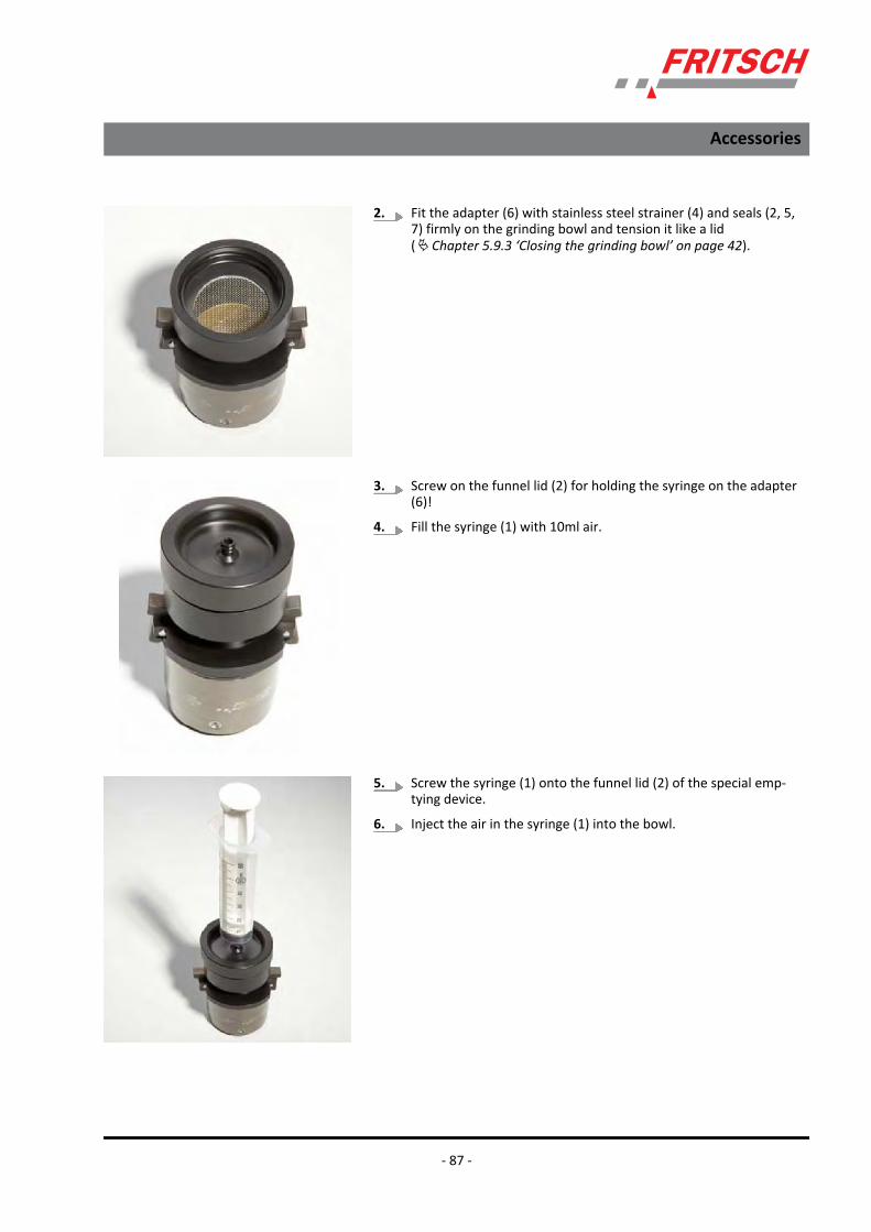
2. Fit the adapter (6) with stainless steel strainer (4) and seals (2, 5,7) firmly on the grinding bowl and tension it like a lid(Ä Chapter 5.9.3 ‘Closing the grinding bowl’ on page 42).
3. Screw on the funnel lid (2) for holding the syringe on the adapter(6)!
4. Fill the syringe (1) with 10ml air.
5. Screw the syringe (1) onto the funnel lid (2) of the special emp-tying device.
6. Inject the air in the syringe (1) into the bowl.
Accessories
- 87 -

7. Shake the bowl with the suspension.
8. Pump 2-5 times with the syringe and then mount the syringe (1).
9. Now, the suspension is in the syringe.
10. Unscrew the syringe (1) from the funnel lid (2).
11. Solvent can again be injected into the bowl using the emptiedsyringe to extract the last remains of the sample, Repeat the pro-cedure 5 to 10 times.
12. Open the system by turning the funnel lid (2) down and separatethe adapter (6) by pushing the locking hooks off the grinding bowl.
13. The suspension is in the syringe and the balls are lying on thestainless steel strainer (4)!
6.4.3 Cleaning the special emptying deviceIt is cleaned under running water. To do this, remove all parts to be ableto clean the seals properly as well. Then dry the parts with a cloth or ablow-dryer. During installation, pay attention to the correct sequenceand position of the seals (see Ä Chapter 6.4.1 ‘Design’ on page 86).
Accessories
- 88 -

2 Funnel lid for special emptying device3 Flat seal, 58x41x2.04 Stainless steel strainer5 Flat seal, 50.5x41x1.56 Adapter for special emptying device7 O-ring, 49x4
6.5 Compl. counterweightThe device is generally subject to a specific imbalance during operation.To keep this imbalance as low as possible, all rotating masses in thesystem must be balanced as completely as possible.
To ensure optimum mass balancing (imbalance correction) of the device,identical weights must always be used at both grinding stations(Ä Chapter 5.10 ‘Mass balance’ on page 47).
The counterweight is used for weight balancing if only one grinding bowlis inserted with a sample in the p-7 premium line.
6.5.1 Design1 Lock nut2 Rubber washer3 Counterweights, 25 g each4 Bowl counterweight
Accessories
- 89 -

6.5.2 Handling1 Lock nut2 Rubber washer3 Compensating washers, 25 g each4 Counterweight5 2-hole face wrench6 Pipe wrench
1. Determine the weight of the grinding bowl to be used with lid,material to be ground and balls.
2. Then, weigh the counterweight (4) and fit compensating washers(3) until the complete weight (with rubber washer (2) and lock nut(1)) of the complete counterweight matches the weight of thecompletely filled grinding bowl. (+/-12.5 g)
3. The spring must be pressed to be able to insert the washers.
4. Make sure that the green rubber washer (2) is lying at the top.
5. Now turn the lock nut (1) onto the threaded spindle. To do this,push the spring back.
6. Turn the lock nut (1) by hand until it touches the rubber washer(2).
Accessories
- 90 -

7. Now, insert the 2-hole face wrench (5) in the 2 holes of the bowl.
8. Tighten the lock nut (1) very firmly using the pipe wrench (6).
CAUTION!Check after the first 5 minutes of grinding if the lock nut hasbeen released. If that is the case, it must be firmly re-tight-ened.
6.6 Planetary mills - "MillControl" software
The PULVERISETTE 7 premium line planetary mill is con‐trolled either at the device using the clearly arranged touchdisplay or with the MillControl software. The software pro‐vides the user with all device controlling options and addsfurther aspects to the operation of the planetary ball mills,like the conduction of identical grinding cycles, but alsogrinding operations using the SOPs. In addition, you alsohave the option of having your grinding operations evalu‐ated in detail in standardised reports with the relevantparameters. If an EASY GTM system is used, all importantdata of this system can be displayed in the program.
Detailed information on the "MillControl" software is avail‐able in the corresponding software manual.
Accessories
- 91 -

7 General and optional settings7.1 Standard Operation Procedure
It is possible to protect this device by applying SOP mode. If this mode isactivated by the administrator, only stored programs can be loaded foroperation. Parameters can no longer be changed. Some parts of themenu structure can no longer be selected.
General and optional settings
- 92 -

7.1.1 Activating SOP mode1. Enter a number between 1 and 9999;
2. Then "Save" it;
3. Press the "<" button to return to the main menu.
ð SOP mode is displayed in the main menu.
7.1.2 Deactivating SOP modeTo disable the restrictions for changing parameters, enter the pin codeand press the "ENTER" button. Press the "<" button to return to the mainmenu.
If the device is switched off, SOP mode is active again.
General and optional settings
- 93 -
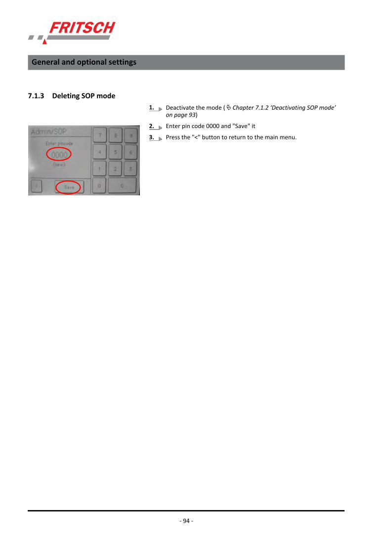
7.1.3 Deleting SOP mode1. Deactivate the mode (Ä Chapter 7.1.2 ‘Deactivating SOP mode’
on page 93)
2. Enter pin code 0000 and "Save" it
3. Press the "<" button to return to the main menu.
General and optional settings
- 94 -

7.2 RFIDIf the bowl is damaged, the bowl detection can be deactivated.
Because the RFID detection is a safety system that cannot simply bedeactivated, it is protected by a pin code.
This pin code can only be obtained by consulting Fritsch GmbH.
General and optional settings
- 95 -

7.3 Language changeAfter selecting the national language, all other texts are displayed in theselected language.
Press the "<" button to confirm your entry and return to the main menu.
General and optional settings
- 96 -

7.4 Screen brightnessThe screen's brightness can be adjusted individually. To do this, touchthe adjustment bar or move it back and forth by applying slight pressure.
Press the "<" button to save your entry and return to the main menu.
General and optional settings
- 97 -

7.5 InformationThe "INFO" button can be pressed to access system information.
The
n operating hours,n the firmware version andn the bowl materials are displayed here (if they were detected during
a START procedure).n Press the "<" button to return to the main menu.
General and optional settings
- 98 -
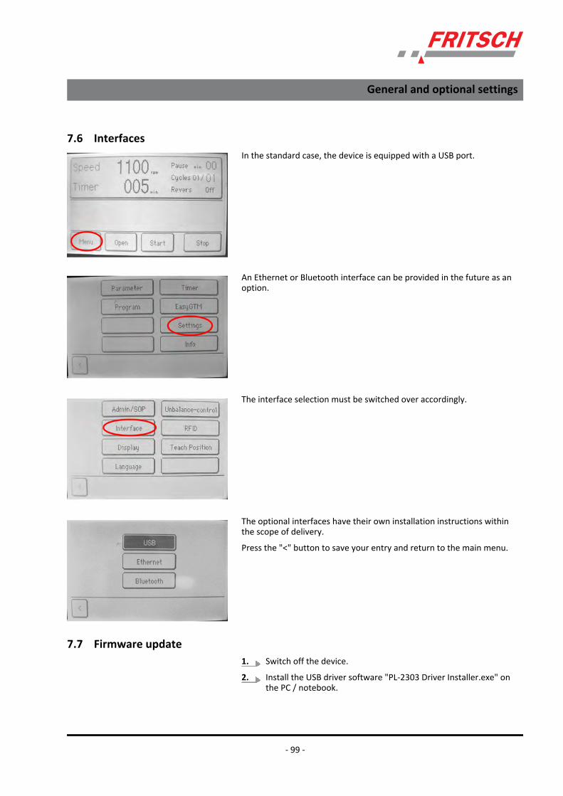
7.6 InterfacesIn the standard case, the device is equipped with a USB port.
An Ethernet or Bluetooth interface can be provided in the future as anoption.
The interface selection must be switched over accordingly.
The optional interfaces have their own installation instructions withinthe scope of delivery.
Press the "<" button to save your entry and return to the main menu.
7.7 Firmware update1. Switch off the device.
2. Install the USB driver software "PL-2303 Driver Installer.exe" onthe PC / notebook.
General and optional settings
- 99 -

3. Connect the USB cable and only then switch on the device. TheUSB port is now automatically activated.
4. Start the 'PROGRAMMER.EXE' software and then select the firm-ware file for programming.
5. Select the newly installed COM port here
6. Press 'Program' to start the update.
7. After programming
8. Now, connect the flasher software.
9. Switch off the planetary micro mill (not the computer!) for a fewseconds.
10. Switch the device back on again
ð Finished!!
General and optional settings
- 100 -

8 Cleaning8.1 Grinding elements
Clean the grinding bowl and grinding balls each time after using them:e.g. clean them under running water using a brush and a commerciallyavailable cleaning agent.
Add sand and water until the grinding bowl is about half full and "grindto clean" for 2 to 3 minutes in the laboratory planetary mill.
Cleaning with an ultrasonic cleaner is permitted.
For sterilisation in the heat cabinet, only heat the grinding elements upto 120°C.
Grinding elements made of agate may only be heated up to 100°C.
CAUTION!Cool grinding elements made of agate, sintered corundum,zirconium oxide and silicon nitride slowly and carefully.
Do not heat the grinding elements in a microwave underany circumstances (heating is too fast).
They must never be exposed to thermal shocks as thiscould cause irreparable damage to the parts → They will fallapart in an explosive manner.
8.2 Mill
DANGER!Mains voltage!– Before beginning with cleaning work, disconnect the
mains plug and protect the device against being unin-tentionally switched back on!
– Do not allow any liquids to flow into the device.– Indicate cleaning work with warning signs.– Put safety equipment back into operation after
cleaning work.
The micro mill can be wiped down with a damp cloth when it is switchedoff.
The grinding chamber can be cleaned thoroughly with a damp cloth byremoving the grinding chamber cover.
Cleaning
- 101 -

8.2.1 Removing the grinding chamber cover1. Remove the 4 screws from the side of the housing using a screw-
driver.
2. Then, carefully tilt the grinding chamber cover to the right.
3. 3 connectors now need to be released.
4. After doing this, the cover can be lifted off completely and thegrinding chamber can be cleaned.
5. To fit the grinding chamber cover, proceed in the reverse order.
DANGER!Do not allow any liquids to flow into the device.
Cleaning
- 102 -
9 Maintenance
DANGER!Mains voltage!– Maintenance work may only be performed by special-
ised personnel.– Before beginning with maintenance work, unplug the
mains plug and protect the device against being unin-tentionally switched back on.
– Put safety equipment back into operation after mainte-nance work.
– Indicate maintenance work with warning signs.
We recommend keeping a safety logbook Ä Chapter 12‘Safety logbook’ on page 108, where all work (maintenance,repairs......) performed on the device is entered.
– The most important element of maintenance is regularcleaning:
– When cleaning the complete device, adhere to theguidelines of the Accident Prevention Regulation (BGVA3) ‐ especially if the device has been set up in a dustyenvironment or if the processed source material pro‐duces dust.
Maintenance
- 103 -
10 Guarantee termsAs manufacturer, FRITSCH GmbH provides – above and beyond any guar-antee claims against the seller – a guaranty valid for the duration of twoyears from the date of issue of the guarantee certificate supplied withthe device.
Within this guarantee period, we shall remedy all deficiencies due tomaterial or manufacturing defects free of charge. Rectification may takethe form of either repair or replacement of the device, at our sole discre-tion. The guarantee may be redeemed in all countries in which thisFRITSCH device is sold with our authorisation.
This guarantee is subject to the condition that the device is operatedaccording to the instructions for use / operating manual and its intendeduse.
Claims against the guarantee must include presentation of the originalreceipt, stating the date of purchase and name of the dealer, togetherwith the complete device type and serial number.
For this guarantee to take effect, the answer card entitled "Securing ofGuarantee" (enclosed with the device) must be properly filled out anddespatched without delay after receipt of the device and be receivedby us within three weeks or alternatively, online registration must becarried out with the above-mentioned information.
The guarantee will not be granted in cases where:
n Damage has arisen due to normal wear and tear, especially for wearparts, such as: Crushing jaws, support walls, grinding bowls, grindingballs, sieve plates, brush strips, grinding sets, grinding disks, rotors,sieve rings, pin inserts, conversion kits, sieve inserts, bottom sieves,grinding inserts, cutting tools, sieve cassettes, sieve and measuringcell glasses.
n Repairs, adaptations or modifications were made to the device byunauthorized persons or companies.
n The device was not used in a laboratory environment and/or hasbeen used in continuous operation.
n Damage is present due to external factors (lightning, water, fire orsimilar) or improper handling.
n Damage is present that only insubstantially affects the value orproper functioning of the device.
n The device type or serial number on the device has been changed,deleted, removed or in any other way rendered illegible
n The above-mentioned documents have been changed in any way orrendered illegible.
Guarantee period
Conditions for claims against the guar-antee
Reasons for loss of the guarantee
Guarantee terms
- 104 -

This guarantee excludes any costs for transport, packaging or travel thataccrue in the event the product must be sent to us or in the event thatone of our specialist technicians is required to come to your site. Anyservicing done by persons not authorised by us and any use of parts thatare not original FRITSCH accessories and spare parts will void the guar-antee.
The guarantee period will neither extend nor will a new period of guar-antee begin in the event that a claim is placed against the guarantee.
Please provide a detailed description of the type of error or the com-plaint. If no error description is enclosed, we shall interpret the shipmentas an assignment to remedy all recognisable errors or faults, includingthose not covered by the guarantee. Errors or faults not covered by theguarantee shall in this case be rectified at cost.
We recommend reading the operating manual before contacting us oryour dealer, in order to avoid unnecessary inconvenience.
Ownership of defective parts is transferred to us with the delivery of thereplacement part; the defective part shall be returned to us at buyer'sexpense.
NOTICE!Please note that in the event that the device must bereturned, the device must be shipped in the original Fritschpackaging. Fritsch GmbH denies all liability for any damagedue to improper packaging (packaging not from Fritsch).
Any enquiries must include a reference to the serial number imprintedon the type plate.
Costs not covered by the guarantee
Further information about the guar-antee
Guarantee terms
- 105 -
11 Exclusion of liabilityBefore using the product, be sure to have read and understood thisoperating manual.
The use of the product requires technical knowledge; only commercialuse is permitted.
The product may be used exclusively within the scope of applications setdown in this operating manual and within the framework of guidelinesput forth in this operating manual and must be subject to regular main-tenance. In case of non-compliance, improper use or improper mainte-nance, the customer assumes full liability for the functional capability ofthe product and for damage or injury arising from violating these obliga-tions.
The contents of this operating manual are subject in entirety to copy-right law. This operating manual and its contents may not be copied, fur-ther distributed or stored in any form, in part or in whole, without theprior written consent of Fritsch.
This operating manual has been prepared to the best of our knowledgeand checked for accuracy at the time of printing. FRITSCH GMBHassumes no guarantee or liability whatsoever for the accuracy or com-pleteness of the contents of this operating manual, including but notlimited to the implied warranties of merchantability and fitness for a par-ticular purpose, unless liability is expressly prescribed by applicable lawsor jurisprudence.
FRITSCH GMBH expressly reserves the right to modify and/or update thisoperating manual without prior notice. The same applies to modifica-tions and improvements to the products described in this operatingmanual. It is the responsibility of the user to ensure that they have thecurrent version of this operating manual. For more information, pleasecontact your local FRITSCH GMBH distributor or Fritsch GmbH, Industri-estr. 8, D-55473 Idar-Oberstein.
Not all parts shown here are necessarily installed in the product. Thebuyer is not entitled to delivery of these parts. If interested, please con-tact your local FRITSCH GMBH distributor or Fritsch GmbH, Industriestr.8, D-55743 Idar-Oberstein.
FRITSCH GMBH takes the greatest care to ensure that the quality, relia-bility and safety of your products are continuously improved andadapted to the state of the art. The supplied products as well as thisoperating manual conform to the current state of the art when theyleave the sphere of influence of FRITSCH GMBH.
By using the product the customer agrees with this and recognizes thatdefects, malfunctions or errors cannot be completely excluded. To pre-vent risk of damage to persons or property or of other direct or indirectdamage, resulting from this or other causes, the customer must imple-ment sufficient and comprehensive safety measures for working with theproduct.
Exclusion of liability
- 106 -

Fritsch GmbH excludes any liability, warranty, or other obligation to com-pensate for damages, regardless of whether this liability, warranty, orother obligation is explicit or implicit, contractual or arising fromunlawful acts or prescribed contractually, by law, or otherwise. In noevent shall the buyer be entitled to any compensation from FritschGmbH for any special, direct, indirect, coincidental or consequentialdamage, including but not limited to lost profits, lost savings, lost salesor financial loss of any kind or for compensation of third parties, fordowntimes, for lost goodwill, for damage to or replacement of equip-ment and property, for costs or restoration of materials or goods relatedto the product or the use of our products, for other damage or injury topersons (including fatal injuries) or similar. The above exclusion of lia-bility is limited by mandatory liability as prescribed by laws or jurispru-dence. Liability for negligence is excluded in all cases.
No permission is given expressly, implicitly or otherwise for the use ofpatents, brands or other copyrights. We also assume no liability for copy-right infringements or infringements of the rights of third parties arisingfrom the use of this product.
Neither compliance with this operating manual nor the conditions andmethods used during installation, operation, use and maintenance of theproduct can be monitored by Fritsch GmbH. Improper execution of theinstallation can result in property damage and thus endanger persons.Therefore, we assume absolutely no responsibility or liability for loss,damage or costs that result from errors at installation, improper opera-tion or improper use or improper maintenance or are in any way con-nected to these.
Exclusion of liability
- 107 -

12 Safety logbookDate Maintenance / Repair Name Signature
Safety logbook
- 108 -

13 IndexAAccident prevention . . . . . . . . . . . . . . . . . . . . . . . . 8Activating EASY GTM . . . . . . . . . . . . . . . . . . . . . . 78Activating SOP mode . . . . . . . . . . . . . . . . . . . . . . 93Adjustment options of the transmitter detection . . . 74Ambient conditions . . . . . . . . . . . . . . . . . . . . . . . 22Authorised persons . . . . . . . . . . . . . . . . . . . . . . . . 8
BBattery arrangement . . . . . . . . . . . . . . . . . . . . . . 85
CCase content
EASY GTM . . . . . . . . . . . . . . . . . . . . . . . . . . . 71Cleaning
Grinding elements . . . . . . . . . . . . . . . . . . . . . 101the mill . . . . . . . . . . . . . . . . . . . . . . . . . . . . 101the special emptying device . . . . . . . . . . . . . . . 88
Cleaning the EASY GTM system . . . . . . . . . . . . . . . 83Cleaning the sensor . . . . . . . . . . . . . . . . . . . . . . . 84Closing the grinding bowl . . . . . . . . . . . . . . . . . . . 42Conduction of a grinding operation . . . . . . . . . . . . 48Configuration of transmitter ID . . . . . . . . . . . . . . . 74Cooling the grinding bowl . . . . . . . . . . . . . . . . . . . 58Counterweight . . . . . . . . . . . . . . . . . . . . . . . . . . . 89Current consumption . . . . . . . . . . . . . . . . . . . . . . 18
DDeactivate bowl detection . . . . . . . . . . . . . . . . . . 95Deactivating EASY GTM . . . . . . . . . . . . . . . . . . . . 82Deactivating SOP mode . . . . . . . . . . . . . . . . . . . . 93Deleting SOP mode . . . . . . . . . . . . . . . . . . . . . . . 94Design
of a grinding bowl . . . . . . . . . . . . . . . . . . . . . . 40of the counterweight . . . . . . . . . . . . . . . . . . . . 89
Device safety information . . . . . . . . . . . . . . . . . . . 13Dimensions . . . . . . . . . . . . . . . . . . . . . . . . . . . . . 18Dry grinding . . . . . . . . . . . . . . . . . . . . . . . . . . . . . 38
EEASY GTM . . . . . . . . . . . . . . . . . . . . . . . . . . . . . . 71Effect of high temperature . . . . . . . . . . . . . . . . . . 39Electrical connection . . . . . . . . . . . . . . . . . . . . . . 22Electrical fuses . . . . . . . . . . . . . . . . . . . . . . . . . . . 19Electrical safety . . . . . . . . . . . . . . . . . . . . . . . . . . 17Entering the pressure limit . . . . . . . . . . . . . . . . . . 81Entering the temperature limit . . . . . . . . . . . . . . . 80Exclusion of liability . . . . . . . . . . . . . . . . . . . . . . 106Explanation of signs . . . . . . . . . . . . . . . . . . . . . . . 10Explanation of symbols . . . . . . . . . . . . . . . . . . . . . 10
FFilling quantities of grinding bowls . . . . . . . . . . . . . 36Filling the grinding bowl . . . . . . . . . . . . . . . . . . . . 36Final fineness . . . . . . . . . . . . . . . . . . . . . . . . . . . . 19Firmware update . . . . . . . . . . . . . . . . . . . . . . . . . 99Fitting the gassing lid on the grinding bowl . . . . . . . 60Fitting the gassing lid swagelok . . . . . . . . . . . . . . . 67function check . . . . . . . . . . . . . . . . . . . . . . . . . . . 24
GGassing lid Swagelok . . . . . . . . . . . . . . . . . . . . . . 66
Scope of delivery . . . . . . . . . . . . . . . . . . . . . . . 66Grinding bowl lid . . . . . . . . . . . . . . . . . . . . . . . . . 31Grinding duration . . . . . . . . . . . . . . . . . . . . . . 37, 47Guarantee terms . . . . . . . . . . . . . . . . . . . . . . . . 104
HHandling of the counterweight . . . . . . . . . . . . . . . 90Handling the special emptying device . . . . . . . . . . . 86Hazardous points . . . . . . . . . . . . . . . . . . . . . . . . . 16Hose adapter for grinding bowl gassing . . . . . . . 62, 69
IImbalance check . . . . . . . . . . . . . . . . . . . . . . . . . 56Imbalance detection . . . . . . . . . . . . . . . . . . . . . . . 17Impact
of the ball size . . . . . . . . . . . . . . . . . . . . . . . . 35of the material . . . . . . . . . . . . . . . . . . . . . . . . 35
Initial start-up . . . . . . . . . . . . . . . . . . . . . . . . . . . 24Inserting / changing the battery in the transmissionunit of the EGTM . . . . . . . . . . . . . . . . . . . . . . . . . 72Inserting the grinding bowl . . . . . . . . . . . . . . . . . . 44Installation of the receiver board . . . . . . . . . . . . . . 77Installation of the transmission unit . . . . . . . . . . . . 75Intended use . . . . . . . . . . . . . . . . . . . . . . . . . . . . . 8Interfaces . . . . . . . . . . . . . . . . . . . . . . . . . . . . . . 99
LLanguage setting . . . . . . . . . . . . . . . . . . . . . . . . . 96Loading the program . . . . . . . . . . . . . . . . . . . . . . 54
MMass balance . . . . . . . . . . . . . . . . . . . . . . . . . . . . 47Material . . . . . . . . . . . . . . . . . . . . . . . . . . . . . . . 19Menu item
Program . . . . . . . . . . . . . . . . . . . . . . . . . . . . . 53MillControl Software . . . . . . . . . . . . . . . . . . . . . . 91
NNumber of balls per grinding bowl . . . . . . . . . . . . . 34
Index
- 109 -

OOpening the grinding bowl . . . . . . . . . . . . . . . . . . 41Operating noise . . . . . . . . . . . . . . . . . . . . . . . . . . 18Operating principle . . . . . . . . . . . . . . . . . . . . . . . . 9Overload . . . . . . . . . . . . . . . . . . . . . . . . . . . . . . . 53Overload protection . . . . . . . . . . . . . . . . . . . . . . . 17Overpressure relief of the grinding bowls . . . . . . . . 29
PPower consumption . . . . . . . . . . . . . . . . . . . . . . . 18Program sequence after switching on . . . . . . . . . . . 49Protection against restart . . . . . . . . . . . . . . . . . . . 17Protective equipment . . . . . . . . . . . . . . . . . . . . . . 15
RRemoving the gassing lid . . . . . . . . . . . . . . . . . . . . 63Removing the gassing lid swagelok . . . . . . . . . . . . . 69Removing the grinding bowl . . . . . . . . . . . . . . . . . 45Removing the grinding chamber cover . . . . . . . . . 102Replacing the seal . . . . . . . . . . . . . . . . . . . . . . . . 84Requirements for the user . . . . . . . . . . . . . . . . . . . 8Reversing mode . . . . . . . . . . . . . . . . . . . . . . . . . . 37
SSafety information . . . . . . . . . . . . . . . . . . . . . . . . 10Safety information for using the device . . . . . . . . . 27Safety logbook . . . . . . . . . . . . . . . . . . . . . . . . . . 108Safety measures against an excessively high pres-sure . . . . . . . . . . . . . . . . . . . . . . . . . . . . . . . . . . 40Saving the current data . . . . . . . . . . . . . . . . . . . . . 54Scope of delivery . . . . . . . . . . . . . . . . . . . . . . . . . 59Screen brightness . . . . . . . . . . . . . . . . . . . . . . . . . 97
Selecting the grinding balls . . . . . . . . . . . . . . . . . . 31Selecting the grinding bowl . . . . . . . . . . . . . . . . . . 31Selecting the operating mode for Easy GTM . . . . . . 82Set-up . . . . . . . . . . . . . . . . . . . . . . . . . . . . . . . . . 21Setting the time control . . . . . . . . . . . . . . . . . . . . 55Size of the grinding balls . . . . . . . . . . . . . . . . . . . . 33Skilled workers . . . . . . . . . . . . . . . . . . . . . . . . . . . 8Special emptying device for grinding bowls . . . . . . . 85Speed . . . . . . . . . . . . . . . . . . . . . . . . . . . . . . . . . 37Standard gassing lid . . . . . . . . . . . . . . . . . . . . . . . 59Standard Operation Procedure . . . . . . . . . . . . . . . 92Starting grinding at high speed . . . . . . . . . . . . . . . 52Switching off . . . . . . . . . . . . . . . . . . . . . . . . . 26, 57Switching on . . . . . . . . . . . . . . . . . . . . . . . . . . . . 24System information . . . . . . . . . . . . . . . . . . . . . . . 98
TTransmission frequency setting options . . . . . . . . . 75
UUnpacking . . . . . . . . . . . . . . . . . . . . . . . . . . . . . . 20Useful capacity of the grinding bowls . . . . . . . . . . . 33
VVoltage . . . . . . . . . . . . . . . . . . . . . . . . . . . . . . . . 18
WWarning information . . . . . . . . . . . . . . . . . . . . . . 10Weight . . . . . . . . . . . . . . . . . . . . . . . . . . . . . . . . 18Weight of a ball . . . . . . . . . . . . . . . . . . . . . . . . . . 35Wet grinding . . . . . . . . . . . . . . . . . . . . . . . . . . . . 38
Index
- 110 -

© 2012
Fritsch GmbHMilling and SizingIndustriestraße 8D - 55743 Idar-ObersteinTelephone: +49 (0)6784/ 70-0Fax: +49 (0)6784/ 70-11email: [email protected]: www.fritsch.de