plan of operations for mining activities on national forest ... - oregon...
TRANSCRIPT
November 8th 2012 Page 1 of 25
PLAN OF OPERATIONS FOR MINING ACTIVITIES
ON NATIONAL FOREST SYSTEM LANDS Data Sheet submitted by: LithoLogic Resources, LLC and Alyssum Ventures LTD, agents for Red Flat Nickel Corp. 12th November 2012
I. GENERAL INFORMATION A. Name of Mine/Project: Red Flat Confirmation Drilling Program B. Type of Operation: Exploration of lode mining claims (see attached claim list in Appendix A) C. Continuing Operation (Phase II) D. Proposed start-up date (mm/dd/yy) of operation: Earliest, 03/01/13, or upon receipt of permit E. Expected total duration of this operation: 4 to 6 weeks F. If seasonal, expected date (mm/dd/yy) of annual reclamation/stabilization close out: n/a G Expected date (mm/dd/yy) for completion of all required reclamation: 4 to 6 weeks after start up to 08/31/13
II. PRINCIPALS A. Name, address and phone number of operator: Red Flat Nickel Corp. c/o John A. Magliana, Jr., Cable Huston LLP,
B. Name, address, and phone number of authorized field representative (if other than the operator). Attach authorization to act on behalf of operator. LithoLogic Resources, LLC; C. Name, address and phone number of owners of the claims (if different than the operator): St Peter Port Capital Ltd.
D. Name, address and phone number of any other lessees, assigns, agents, etc., and briefly describe their involvement with the operation, if applicable: Alyssum Ventures Ltd.
Project Management Company
November 8th 2012 Page 2 of 25
III. PROPERTY OR AREA
Name of claim, if applicable and the legal land description where the operation will be located. ORMC# Name Township Range Sections 161335-161434 RF #1 thru #114 37S 14W 13, 24 and 25
37S 13W 18, 19, 30, 31 & 32 See Appendix A for claim information.
IV. DESCRIPTION OF THE OPERATION Overview The Red Flat property was identified and explored by the United States Geological Society (USGS), United States Bureau of Mines (USBM) and the Oregon Department of Geology and Mineral Industries (DOGAMI) in the years up to 1978 and was found to contain significant occurrences of the strategically important metals nickel, cobalt and chromium. From 2007 to 2009 the claimant completed additional surface sampling and drilling, including approximately 5,600 feet of drilling in 652 shallow auger holes, bulk sampling and 12 deeper sonic drill holes across the claim block. Exploration to date has indicated potentially economic concentrations of the strategic metals nickel, cobalt, and chromium, but failed to reach the base of the mineralized horizon. The claimant intends to continue sub-surface exploration through a limited deeper drilling program of approximately 1,500 feet of additional drilling in 35 drillholes to delineate mineralization at depth and to confirm the results of the prior work. Due to their rust-inhibiting properties, nickel and chromium are used predominantly in the manufacture of stainless steels, which have important applications in surgical instruments, household utensils, and many other items. Nickel is also increasingly important for use in hydrogen and electrically powered vehicles. Cobalt is an important alloying metal, with applications in the aerospace and wind turbine industries. A. Access. Show on a map (USGS quadrangle map or a National Forest map, for example) the claim boundaries, if applicable, and all access needs such as roads and trails, on and off the claim. Specify which Forest Service roads will be used, where maintenance or reconstruction is proposed, and where new construction is necessary. For new construction, include construction specifications such as widths, grades, etc., location and size of culverts, describe maintenance plans, and the type and size of vehicles and equipment that will use the access routes. Access into the claim block is via Hunter Creek Road, which joins US Highway 101 approximately 2 miles south of Gold Beach, Oregon. Approximately 5 miles up from Hwy. 101, Road 3680 allows access into the northern portions of the claim block, with Road 1703 coming in from the south and transiting across the top of Red Flat (See Figure 1). There are also a number of existing secondary roads on the claim block area which are believed to be old access roads developed by the USGS and/or DOGAMI. No new road construction will be necessary for this project.

November 8th 2012 Page 3 of 25
Figure 1: Project Location and Access

November 8th 2012 Page 4 of 25
B. Map, Sketch or Drawing. Show location and layout of the area of operation. Identify any streams, creeks or springs if known. Show the size and kind of all surface disturbances such as trenches, pits, settling ponds, stream channels and run-off diversions, waste dumps, drill pads, timber disposal or clearance, etc. Include sizes, capacities, acreage, amounts, locations, materials involved, etc. See Figure 2

November 8th 2012 Page 5 of 25
Figure 2: Red Flat Claim Block Map

November 8th 2012 Page 6 of 25
Figures 3 and 4 (below) are site photographs that show Forest Road 1703 and a typical secondary access track on the property, respectively. Figure 3: Forest Road 1703 on the claim block Figure 4: Typical secondary access road at Red Flat Much of the area shows evidence of previous mineral exploration disturbance as evidenced by the presence of the secondary roads and numerous open trench excavations. The drill will operate from a raised, 4 ft. by 11 ft. metal platform to be temporarily set up at each drill location. The drill will be moved to the drill location by truck and lifted by a truck-mounted boom onto the raised drilling platform positioned over the hole location. The platform will support the drill above the surface, with the fuel and water tanks kept on-board the truck. The drill crew and logging geologist will work around the platform, utilizing an additional maximum area of 5 feet in each direction. Thus, for each drill hole an area of 21 ft. x 14 ft. will be occupied by the drill platform and working area plus 13 ft. by 16 ft. for the support truck and working area, for a total of 502 ft2. In addition, either a water tank or water truck will be placed on the southern portion of the deposit to provide the required supply of water for the drill rig. The water tank (or water truck) will be re-filled as necessary to maintain adequate water supplies for the drilling program. The water will be municipal water sourced from Gold Beach and transferred to the site via water truck.

November 8th 2012 Page 7 of 25
Figure 5: Sketch of drilling area and set-up
In addition, there will be a towed (or truck mounted) water carrier and one 4WD vehicle parked on the roadside at each test location. Both are estimated to occupy 72 square feet each. A breakdown of each area and the anticipated surface impact during the program is contained in Table 1.
Table 1: Anticipated Surface Disturbance
*It should be noted that these “anticipated disturbance” areas all occur on previously disturbed road surfaces. As such, there will not be any new disturbance of previously un-disturbed ground associated
Drill
Hole in platformfor drill string
Raised metalplatform
Working area5’
4’
11’
Adjustablemetal legs
5’
5’
5’
Water
tankFueltank
Truck
5’
Waterline
Fuelline
12’
6’
1’
Size Number Total NotesSq feet Sq feet
Drill areas* 294 35 10,290 Includes platform and working area around platform, both locations
Drill truck* 208 35 7,280 Includes working area. Both locationsWater carrier* 72 35 2,520 Both locationsParked 4WD vehicle* 72 35 2,520 Both locationsWater Storage Tank* 100 1 100 Central water storage tankBrush Removal on Road 3,600 2 7,200 Assumes 1,200 linear feet of road and 3 ft width on each side
Sq feet 29,910 Acres 0.69
Area in use at any one time Sq feet 4,346 Acres 0.10

November 8th 2012 Page 8 of 25
with the drill areas, drill truck, water carrier, parked 4WD vehicle, or the water storage tank. The removal of brush along the approximately 1,200 feet of existing roadway will also only include removal of dead trees that have fallen across the roadway and removal of encroaching brush up to the current road footprint.

November 8th 2012 Page 9 of 25
C. Project Description. Describe all aspects of the operation including mining, milling, and exploration methods, materials, equipment, workforce, construction and operation schedule, power requirements, how clearing will be accomplished, topsoil stockpile, waste rock placement, tailings disposal, proposed number of drillholes and depth, depth of proposed suction dredging, and how gravels will be replaced, etc. Calculate production rates of ore. Include justification and calculations for settling pond capacities, and the size of runoff diversion channels. A total of 35 drillholes are planned for this exploration drilling program (see Figure 6 and Table 2). Figure 6: Proposed Drillhole Locations

November 8th 2012 Page 10 of 25
Table 2: Drillhole Coordinates
The drillholes are spaced a minimum of 500 feet apart and cover various areas of the known mineral occurrences. All holes have been located as to be accessible from existing roads and tracks on the claim block area. In addition, each drill location has been placed to avoid unnecessary disturbance to the local fauna and flora such that the drill will penetrate directly into rock or exposed lateritic soils. In addition, no drillholes have been located within 200 feet of any seasonal or perennial watercourse.
Location Feet Meters Northing Easting Northing Easting Latitude LongitudeRFA_001 1,801 549 281,268 3,894,247 85,730 1,186,966 42.37445 124.30199- RFA_002 1,929 588 280,911 3,894,718 85,622 1,187,110 42.37353 124.30019- RFA_003 2,113 644 279,720 3,895,175 85,259 1,187,249 42.37032 124.29830- RFA_004 2,167 660 279,072 3,895,286 85,061 1,187,283 42.36856 124.29778- RFA_005 2,217 676 278,512 3,895,306 84,890 1,187,289 42.36702 124.29761- RFA_006 2,260 689 277,852 3,895,081 84,689 1,187,221 42.36519 124.29833- RFA_007 2,415 736 277,324 3,894,424 84,528 1,187,020 42.36366 124.30067- RFA_008 2,344 715 277,288 3,895,220 84,517 1,187,263 42.36366 124.29773- RFA_009 2,319 707 277,238 3,895,828 84,502 1,187,448 42.36360 124.29547- RFA_010 2,301 701 276,858 3,896,384 84,386 1,187,618 42.36263 124.29335- RFA_011 2,532 772 274,996 3,896,866 83,819 1,187,765 42.35758 124.29125- RFA_012 2,446 745 274,585 3,896,954 83,693 1,187,791 42.35646 124.29086- RFA_015 2,607 795 273,303 3,895,043 83,303 1,187,209 42.35271 124.29771- RFA_016 2,511 765 273,022 3,895,704 83,217 1,187,411 42.35203 124.29522- RFA_017 2,568 783 272,709 3,894,767 83,122 1,187,125 42.35105 124.29863- RFA_018 2,470 753 272,441 3,895,353 83,040 1,187,304 42.35039 124.29642- RFA_019 2,509 765 272,101 3,894,547 82,936 1,187,058 42.34936 124.29934- RFA_020 2,438 743 271,812 3,895,671 82,848 1,187,400 42.34870 124.29514- RFA_021 2,469 753 271,490 3,894,999 82,750 1,187,196 42.34774 124.29757- RFA_022 2,464 751 271,045 3,895,144 82,615 1,187,240 42.34654 124.29696- RFA_023 2,425 739 270,960 3,896,121 82,589 1,187,538 42.34643 124.29333- RFA_024 2,451 747 270,426 3,895,353 82,426 1,187,304 42.34487 124.29608- RFA_025 2,411 735 270,344 3,896,066 82,401 1,187,521 42.34473 124.29343- RFA_026 2,421 738 269,932 3,895,388 82,275 1,187,314 42.34352 124.29587- RFA_027 2,341 713 269,553 3,896,071 82,160 1,187,522 42.34256 124.29328- RFA_028 2,338 713 269,324 3,895,485 82,090 1,187,344 42.34186 124.29541- RFA_029 2,312 705 269,185 3,895,945 82,048 1,187,484 42.34154 124.29369- RFA_030 2,289 698 268,926 3,896,141 81,969 1,187,544 42.34085 124.29292- RFA_032 2,256 688 268,546 3,897,000 81,853 1,187,806 42.33992 124.28968- RFA_033 2,243 684 268,162 3,897,653 81,736 1,188,005 42.33895 124.28721- RFA_034 2,188 667 268,226 3,898,388 81,755 1,188,229 42.33921 124.28450- RFA_035 2,101 640 268,093 3,899,064 81,715 1,188,435 42.33893 124.28198- RFA_036 2,019 615 267,995 3,899,711 81,685 1,188,632 42.33874 124.27957- RFA_037 1,890 576 268,078 3,900,320 81,710 1,188,818 42.33905 124.27734- RFA_038 1,724 525 267,569 3,900,901 81,555 1,188,995 42.33772 124.27510-
Elevation SP, Oregon South, NAD83 (Feet) SP, Oregon South, NAD83 (Meters) Geodetic WGS84
November 8th 2012 Page 11 of 25
Project Area Description The claim block area is characterized by lateritic soils covered with coniferous forest growth and underbrush typical of the wider area. Forest road 1703 crosses the deposit. As the area was extensively explored by the USGS, USBM, DOGAMI and private companies in the period up to 1978, there are numerous non-designated secondary roads that were constructed for exploration activities. Many of these remain open and passable by 4x4 vehicle. In addition, there are a number of east-west trending trenches that were excavated in the area. Drilling Method Drilling will be completed by a low impact, light drilling rig. The drill proposed is a Saitech Viper Drill which is a light diamond core drill that has been designed for difficult access and environmentally sensitive drill sites. Manufactured and operated by VP Salisbury & Associates of Spokane, Washington, the Saitech Viper can be transported to and from drill sites by a small truck. Program Extent A maximum of 35 holes are anticipated to be completed during this phase of the exploration, with an expected average hole depth of 40 feet below ground surface (bgs), an expected maximum drill depth of 50 feet bgs, and a maximum drilled diameter of 3-inches. The drillhole locations are shown on Figure 6, above. Detailed Description The claimant has located all drillholes for this program within the claim block and at the edge of existing USFS roads, or on secondary exploration roads constructed in the past. During the location of the planned drillholes, careful evaluation of drill rig access was considered. Based on the access assessment it was determined that minor brush removal along one road will be necessary to gain access to RF-007 and RF-008. This road has numerous dead trees that have fallen across the road surface that will need to be removed to allow for vehicle access. During removal of the dead trees, limited brushing of the road edges will also occur as the road has been slightly overgrown due to the limited access along this road. All of the work can be completed with a small chainsaw and handheld pruning clippers. The brush along the road edge will be removed to the extent of the existing road surface (previously disturbed area) and disposed into the surrounding area for natural decay. The total linear length of the road to be cleared of downed trees and brush is 1,200 feet. See Figure 7 for the portion of road requiring brush work. No holes will be attempted within 200 feet of any intermittent spring or watercourse. The test holes will be to a maximum depth of 50 feet and at NQ size; (75.7 mm, 3 inch) hole diameter.

November 8th 2012 Page 12 of 25
Figure 7: Location of Road requiring brush work.

November 8th 2012 Page 13 of 25
The drilling operation will consist of the following steps.
• Lifting of the drill rig, fuel tank and water tank on to a Ford F450 dual rear axle truck • Transport of the drill rig to the drill location along existing USFS roads • Transport of water in a water trailer (or in the back of the vehicle) towed by a standard 4x4
vehicle • Photograph taken of the drill location immediately prior to test drilling • Positioning of the drill truck on the side of the road at the drill site and positioning of the water
trailer next to and slightly uphill of the drill at the roadside • Positioning of the drill platform over the intended hole location • Lifting of the drill by truck-mounted boom onto the drilling platform • Connection of water and fuel lines from the tanks on the truck to the drill • Preparation of the drill for drilling and connection from the water trailer to the drill water tank for
water feed by gravity • Commencement of drilling • Recovery of sample core • Measuring of the core to determine degree of sample recovery • Drilling of the next sample length • Termination of the hole once the end of mineralized material has been reached or at 50 feet
drilled, whichever occurs first. • Removal of the drill and all casing from the hole • Drillhole abandonment (see procedure, below) • Disconnection of water and fuel lines • Lifting of the drill back onto the truck • Dismantling and placement of the platform back on the truck • Clean up of the area • Transport to the next hole location and repetition of the steps above
All drill core will be transported by 4WD vehicle to an off-site facility for sampling, analysis, and long-term storage. All drill holes will be plugged and abandoned immediately after completion, in accordance with Oregon Administrative Rules (OAR) 690-220-0030 and OAR 632-033-0025. Excess soil will be spread to a maximum depth of 1-inch, and the area cleaned and returned to natural grade. Reclamation of each hole will thus occur before start of drilling at the next location. Drill locations have been established utilizing a hand-held GPS unit, with no need for the cutting or flagging of survey lines to establish surface control. No holes will be attempted within 200 feet of any intermittent spring or watercourse. Good housekeeping conditions will be maintained at the drill rig and surrounding area at all times.
November 8th 2012 Page 14 of 25
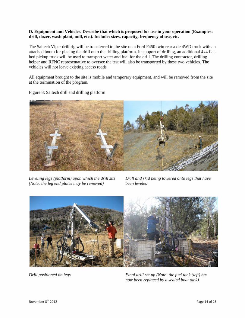
D. Equipment and Vehicles. Describe that which is proposed for use in your operation (Examples: drill, dozer, wash plant, mill, etc.). Include: sizes, capacity, frequency of use, etc. The Saitech Viper drill rig will be transferred to the site on a Ford F450 twin rear axle 4WD truck with an attached boom for placing the drill onto the drilling platform. In support of drilling, an additional 4x4 flat-bed pickup truck will be used to transport water and fuel for the drill. The drilling contractor, drilling helper and RFNC representative to oversee the test will also be transported by these two vehicles. The vehicles will not leave existing access roads. All equipment brought to the site is mobile and temporary equipment, and will be removed from the site at the termination of the program. Figure 8: Saitech drill and drilling platform Leveling legs (platform) upon which the drill sits Drill and skid being lowered onto legs that have (Note: the leg end plates may be removed) been leveled Drill positioned on legs Final drill set up (Note: the fuel tank (left) has now been replaced by a sealed boat tank)
November 8th 2012 Page 15 of 25
E. Structures. Include information about fixed or portable structures or facilities planned for the operation. Show locations on the map. Include such things as living quarters, storage sheds, mill buildings, thickener tanks, fuel storage, powder magazines, pipelines, water diversions, trailers, sanitation facilities including sewage disposal, etc. Include engineering design and geotechnical information for project facilities, justification and calculations for sizing of tanks, pipelines and water diversions, etc. In the event of inclement weather a temporary waterproof tarpaulin will be positioned above the drill rig and will be removed upon completion of operations. No fixed or permanent structures are planned. A large, approximately 5,000 gallon water tank (or potentially a water truck) will be staged at the southern end of the deposit. The purpose of this water storage tank (or truck) is to provide a larger water storage container than is possible in the back of the 4WD vehicle. The tank will be filled prior to beginning of the drilling operation by a water truck as necessary. The water from the tank will either be gravity fed to the water tank on the 4WD vehicle or transferred using a small gas-powered pump. No open fires will be built, and all materials and debris will be removed on a regular basis.
November 8th 2012 Page 16 of 25
V. ENVIRONMENTAL PROTECTION MEASURES (SEE 36 CFR 228.8) Standards and Governance Red Flat Nickel Corp aims to achieve the highest standards of health, safety and environmental performance and the protection of workers, the general public and local communities in areas where we operate. Red Flat Nickel Corp will at all times conduct its work according to:
• The highest standards of health and safety (OHSA) • International Finance Corporation (IFC)’s Policy on Social and Environmental Sustainability,
2006, including the IFC Performance Standards (PS) • The Equator Principles (EPs), 2006 • International Labour Organisation (ILO) conventions • The technical standards of Canadian National Instrument 43-101 • United Nations “Guidance on Good Practices in Corporate Governance Disclosure” • All applicable Federal, State and local laws
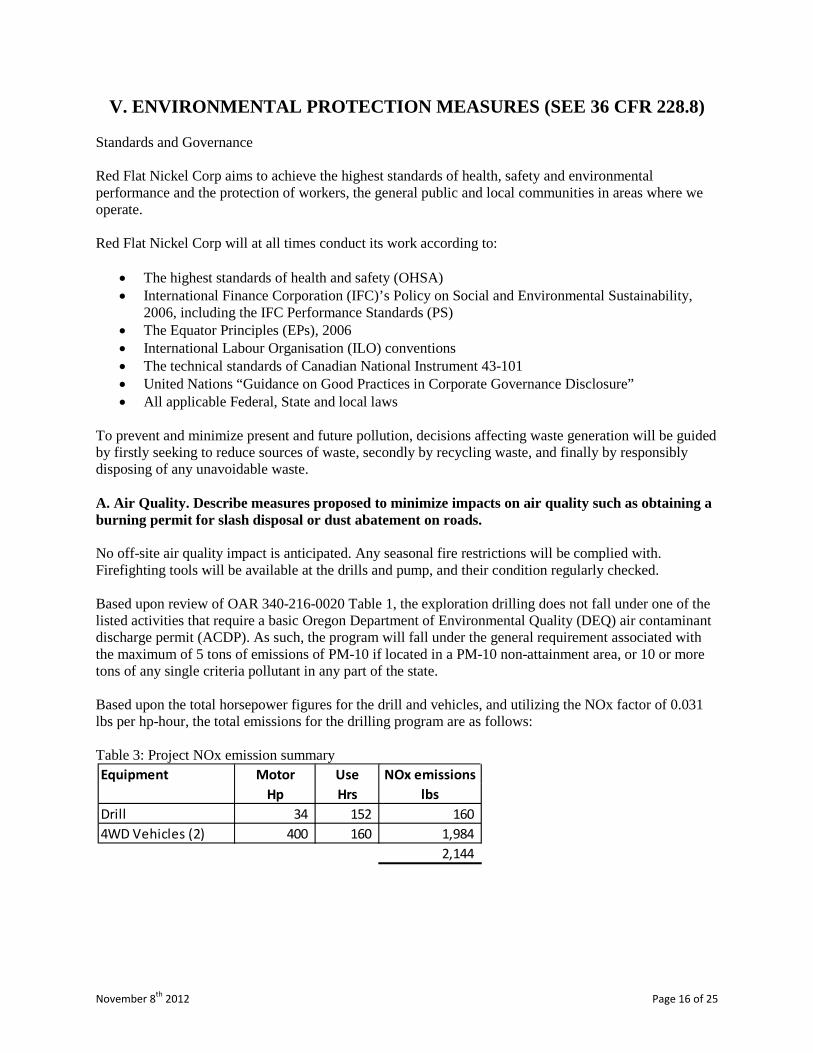
To prevent and minimize present and future pollution, decisions affecting waste generation will be guided by firstly seeking to reduce sources of waste, secondly by recycling waste, and finally by responsibly disposing of any unavoidable waste. A. Air Quality. Describe measures proposed to minimize impacts on air quality such as obtaining a burning permit for slash disposal or dust abatement on roads. No off-site air quality impact is anticipated. Any seasonal fire restrictions will be complied with. Firefighting tools will be available at the drills and pump, and their condition regularly checked. Based upon review of OAR 340-216-0020 Table 1, the exploration drilling does not fall under one of the listed activities that require a basic Oregon Department of Environmental Quality (DEQ) air contaminant discharge permit (ACDP). As such, the program will fall under the general requirement associated with the maximum of 5 tons of emissions of PM-10 if located in a PM-10 non-attainment area, or 10 or more tons of any single criteria pollutant in any part of the state. Based upon the total horsepower figures for the drill and vehicles, and utilizing the NOx factor of 0.031 lbs per hp-hour, the total emissions for the drilling program are as follows: Table 3: Project NOx emission summary
Equipment Motor Use NOx emissionsHp Hrs lbs
Drill 34 152 160 4WD Vehicles (2) 400 160 1,984
2,144
November 8th 2012 Page 17 of 25
B. Water Quality. State how applicable state and federal water quality standards will be met. Describe measures or management practices to be used to minimize water quality impacts and meet applicable standards.
1. State whether water is to be used in the operation, and describe the quantity, source, methods and design of diversions, storage, use, disposal, and treatment facilities. Include assumptions for sizing water conveyance or storage facilities.
Water will be required for the drilling operation. Water of domestic drinking quality will be sourced off site from the Gold Beach municipality and will be transported for the test drilling by a water truck. The water truck will either remain on-site until additional water is required or transfer the water to a water storage tank located at the site. No water will be obtained from sources within the claim area or from any of the local creeks. All drilling will maintain a minimum 200 foot buffer around any seasonal watercourse. It is expected that the water used in drilling will be lost into the subsurface. However, some water may return to surface. Recovery and recycling of this water back into the hole will be attempted with a view to minimizing water use. Any water not recovered and recycled will be allowed to flow into existing roadside drainage ditches. Given the porous nature of the soil and rock at the drill locations, any unrecovered water will be allowed seep into the ground. As the water will be municipal water, no ground water contamination is expected. The total water use for the 35 drillhole locations is not expected to exceed 35,000 U.S. gallons (approximately 1,000 gallons per drillhole).
2. Describe methods to control erosion and surface water runoff from all disturbed areas, including waste and tailings dumps.
Given the porous nature of the stratigraphy, it is anticipated that no water will be returned to the surface during the drilling process, and that all drilling fluids will be lost into the subsurface. In the event that some fluids are returned to the surface, the water will be directed away from the drilling location and allowed to naturally infiltrate. Appropriate erosion control and Best Management Practices (BMPs) will be installed at each site to limit any potential erosional concerns. BMPs will include, but are not limited to, waddles, sediment fencing, sediment traps, etc. All drilling will maintain a minimum 200 foot buffer around any seasonal watercourse.
3. Describe proposed surface water and groundwater quality monitoring, if required, to demonstrate compliance with federal or state water quality standards.
Based on the proposed drilling program, the potential surface disturbances, and the BMPs (maintaining 200’ buffer from surface water courses, only using potable water and non-hazardous bio-degradable drilling additives, etc.), no surface water or groundwater monitoring is proposed for this drilling program.

November 8th 2012 Page 18 of 25
4. Describe the measures to be used to minimize potential water quality impacts during seasonal closures, or for a temporary cessation of operations.
Based upon the short duration of the proposed drilling program (maximum 45 days), no seasonal or temporary cessation of operations is expected. In the event an unplanned cessation of operations occurs, all drilling and support equipment will be removed from the site.
5. If land application is proposed for waste water disposal, the location and operation of the land application system must be described. Also describe how vegetation, soil, and surface and groundwater quality will be protected if land application is used.
No land application of waste water will be completed as part of the project as no waste water will be generated. C. Solid Wastes. Describe the quantity and the physical and chemical characteristics of solid waste produced by the operation. Describe how the wastes will be disposed of including location and design of facilities, or treated so as to minimize adverse impacts. The mineral material on the deposit is the weathering product of ultramafic rock containing oxides of iron and serpentinite minerals. The material at the maximum drilling depth of fifty feet is also found at nearby locations at surface. Thus no sulphide minerals exist within the material and there is no potential for locating any acid generating rocks. All material recovered from the hole as the core sample will be placed in plastic core boxes and transported off-site for further testing and analysis. Non-sampled drill cuttings from the program will be spread to a depth of no greater than 1-inch at each hole location and blended with the natural slope of the land. All unnatural solid wastes will be removed from the each drillhole location before moving on to the next hole. The recovered core samples from each drill hole will not exceed 75 lbs. The unrecovered drill chips will not exceed 100 lbs per hole and 3,500 lbs for the total program. No residual impact is anticipated. D. Scenic Values. Describe protection of scenic values such as screening, slash disposal, or timely reclamation. The Red Flat site is remotely located away from state or county highways, and away from any residential lands. As each hole will be immediately reclaimed upon completion, no visual disturbance is expected to last longer than the time that the hole is actively being prepared, drilled, and reclaimed. Even allowing for unforeseen events such as breakdowns, the period of visual disturbance is not anticipated to exceed 2 days at any one hole. No significant impact is envisaged.

November 8th 2012 Page 19 of 25
E. Fish and Wildlife. Describe measures to maintain and protect fisheries and wildlife, and their habitat (includes threatened, endangered, and sensitive species) affected by the operations. The drilling program has been designed to have no significant impact on fish or wildlife. The program plan ensures that all possible program activities are located at least 200 feet from surface water courses. The point of penetration of drillholes will be positioned directly upon exposed lateritic soils and not through any existing plant life. No hunting will be permitted by the drilling contractor’s crew or RFNC’s representatives. No significant impact is envisaged. F. Cultural Resources. Describe measures for protecting known historic and archeological values, or new sites in the project area. Search of the Curry County Planning Division records, including the current Curry County Comprehensive Plan and the Curry County Natural Resource Document shows that there are no recorded historic sites or areas of archeological significance at the drillhole locations. No significant impact is envisaged. F/2. Other Areas of Significance. There are two recorded areas of significance near the proposed drillhole locations as shown on Figure 9 overleaf.
• Flycatcher Spring Campground • The Hunter Creek Bog
Based on the sensitive nature of these two areas no drillholes have been proposed within these areas. The extent of the Flycatcher Spring area was based on information from Donna Kauffman of the Oregon BLM in an email dated July 10, 2007. According to Ms. Kauffman the Flycatcher Spring Campground area is defined as the SE ¼ of the SW ¼ and the southern portion of the NE ¼ of the SW ¼ of Section 19, Township 37S and Range 13W. The Hunter Creek Bog has been classified as an Area of Critical Environmental Concern (ACEC). No drillholes or other activities are planned within 300 feet of the Hunter Creek Bog. The claimant has excluded these areas from the drilling program and no drill holes are planned within the excluded areas. In addition to the two areas described above, this portion of Curry County also has various areas that suffer from Port Orford Cedar (POC) disease. Based on previous work by the claimant at Red Flat, there is only one road that is seasonally closed in an attempt to prevent the spread of POC disease. This road has a locked gate during the rainy season and is located on the southern portion of the claim block. There are eight drillholes located behind this closed gate (RFA-30, 32, 34, 35, 36, 37, and 38). Prior to entering this road, the vehicles' wheels will be thoroughly cleaned in conformance with the USFS requirements. See Figure 9 for the locations of the Flycatcher Spring, Hunter Creek Bog, and the POC closure area. No significant impact is envisaged.

November 8th 2012 Page 20 of 25
Figure 9: Areas of Significance
Hunter Creek Bog
Flycatcher Spring
Road closedseasonally forPOC diseaseprevention

November 8th 2012 Page 21 of 25
G. Hazardous Substances. 1. Identify the type and volume of all hazardous materials and toxic substances which will be used or generated in the operations including cyanide, solvents, petroleum products, mill, process and laboratory reagents. Onsite drilling equipment that may contain petroleum products:
• Hydraulic power pack – The Saitech Viper’s hydraulic power pack is run by an air-cooled 25 horsepower Kohler gasoline engine. Since the engine is air-cooled there is no antifreeze. The Kohler engine contains approximately 2 U.S. quarts of motor oil. The power pack contains approximately 8 U.S. gallons of hydraulic fluid. The fuel tank on the power pack holds approximately 5 U.S. gallons of gasoline.
• Water pumps – During drilling operation the Saitech Viper drill utilizes 2 water pumps: one to supply water to the drill site and one for pumping water down the hole for bit cooling and removal of cuttings. Each water pump is powered by a 5.5 horsepower air-cooled Honda engine (no antifreeze). The Honda engine contains approximately 1 U.S. quart of motor oil. The fuel capacity of the Honda engine is less than 1 U.S. gallon. In each case, the pump that is coupled to the Honda engine contains 1 U.S. quart or less of motor oil for internal lubrication.
• Viper drill unit – The only component of the actual drill itself that contains any petroleum product is the transmission, which contains approximately 1 U.S. quart of gear oil.
Each Saitech Viper Drill comes complete with the following environmental protection equipment:
• A spill response kit which includes absorbent pads and booms sufficient to contain any petroleum spill that may occur on the drill site.
• Shovels, heavy plastic bags, and hard plastic containers sufficient for collecting and removing any soils or native materials that may become contaminated in the event of a spill.
• Axes, buckets, shovels, and fire extinguishers to be used for fire suppression. • All internal combustion engines used during drilling operation are equipped with USDA Forest
Service approved spark arrestor systems. • Binder containing Material Safety Data Sheets (MSDS) for each hazardous material that may be
used on site. • Metal spill proof safety cans for transporting fuel to and from the drill site. • Kits containing spare parts, seals, and O-rings to repair or rebuild most mechanical components
associated with the drilling operation. In the event of an oil leak or spill, it is the drilling contractor’s policy to immediately shut down the drilling operation, contain and clean up the spill, and perform any necessary repairs. Absorbent matting shall be used at fueling or fuel decanting points and under the drill rig motors. Hydraulic power pack – The Saitech Viper’s hydraulic power pack is run by an air-cooled 25 horsepower Kohler gasoline engine. Since the engine is air-cooled there is no antifreeze. The Kohler engine contains approximately 2 U.S. quarts of motor oil. The power pack contains approximately 8 U.S. gallons of hydraulic fluid. The fuel tank on the power pack holds approximately 5 U.S. gallons of gasoline. Water pumps – During drilling operation the Saitech Viper drill utilizes 2 water pumps: one to supply water from the water carrier to the drill (only used if gravity feeding of the water from the water carrier proves inadequate) and one for pumping water down the hole for bit cooling and removal of cuttings. Each water pump is powered by a 5.5 horsepower air-cooled Honda engine (no antifreeze). The Honda

November 8th 2012 Page 22 of 25
engine contains approximately 1 U.S. quart of motor oil. The fuel capacity of the Honda engine is less than 1 U.S. gallon. In each case the pump that is coupled to the Honda engine contains 1 U.S. quart or less of motor oil for internal lubrication. Viper drill unit – The only component of the actual drill itself that contains any petroleum product is the transmission, which contains approximately 1 U.S. quart of gear oil. Fuel – the drill uses regular gasoline. It is anticipated that total fuel use for the drilling program will not exceed 350 U.S. gallons. The truck and 4x4 vehicles will use diesel fuel. The vehicles will be fueled off-site and no need for fuel on-site is envisaged. 2. For each material or substance, describe the methods, volume, and frequency of transport (include type of containers and vehicles), procedures for use of materials or substances, methods, volume, and containers for disposal of materials and substances, security (fencing), identification (signing/labeling), or other special operations requirements necessary to conduct the proposed operations. An inventory will be developed of hazardous materials brought to site. This inventory is anticipated to include:
• Gasoline • Oil and lubricants • Cleaning products such as detergents, soaps, degreasing agents, and hand cleaners
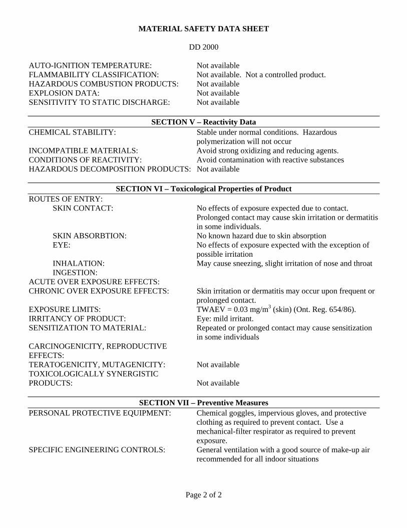
All hazardous materials will have appropriate MSDS’s which will include recommended spill clean-up methods and materials, and define the personal protective equipment required when the substances are used. Gasoline fuel for the drill will be transported to the rig in 5-gallon jerry cans by 4x4 vehicle and stored in appropriate containers in the 4WD vehicle's flat bed next to the drill rig. Only enough fuel for the day's drilling plan will be brought to site each day. This is anticipated to be no more than 20 gallons per day. Fuel storage containers will have secondary containment, with suitable cover, with the capacity of containing a minimum of 110% of the total volume of the fuel jerry cans. Absorbent matting shall be used at fueling or fuel decanting points and under the drill rig motors. All unused fuels will be removed from the site upon completion of the project (or upon premature termination due to weather or fire-risk constraints). Suitable general refuse storage containers will be provided, pending solid waste removal and disposal. Use may also be made of drilling additives. These are substances that are mixed with the drilling water in the drill’s water tank to improve sample recovery, and/or to maintain drillhole stability. The drilling contractor will bring two such substances to the site – “Bio Cut Plus” and “DD-2000”. Both of these substances are classified as non-hazardous and both are biodegradable. The drilling contractor expects to mix two parts Bio Cut Plus to one part DD-2000 and use 1 gallon of the mix per 1,000 gallons of water. The MSDS’s for both substances are attached in Appendix A. The maximum anticipated amount of drill additives to be used is not expected to exceed 10 lbs per hole or 350 lbs in total. Depending upon drilling conditions, no additives may be used at all. The additives are mixed directly to the drill water tank and thus no sump or other mixing area is required.
November 8th 2012 Page 23 of 25
3. Describe the measures to be taken for release of a reportable quantity of a hazardous material or the release of a toxic substance. This includes plans for spill prevention, containment, notification, and cleanup. Every effort will be made to avoid any spillage. Specific mitigation procedures will be available from the drill contractor and will include the following:
• The drill and water pumps will be regularly maintained to prevent leaks of fuel or oil • Provision of absorbent impermeable mats for use during fuel transfer • Provision of emergency spill containment kits
Emergency spill containment kits will at a minimum contain:
• Three (3) 4ft absorbent socks • Biodegradable absorbent material • Four (4) absorbent wipes • One (1) pair of rubber gloves • Two (2) sizes of disposable bags • Shovels • Identification of product labels
During transfer of fuels from jerry cans, the following procedure will be followed:
• Apply Personal Protective Equipment • No smoking, naked lights, open flames, welding or hot work will be allowed in the vicinity of the
fuel drums, particularly when decanting combustible liquids • Inspect vessel to be filled for cleanliness and condition, including drum pump and funnel • Slowly open the fuel drum to allow the vapor expansion of fuel gas to dissipate • Place decant or drip tray below the drum pump • Only fill decanted vessel to 80% of full capacity to allow for vapor expansion • Pack away equipment • Clean up any spill that may have occurred • Re-fueling or decanting of fuels will be restricted to daylight hours
A metal-lipped tray will be installed under the drill rig motors and hydraulic pack, having a capacity of 110% of the total volume of the lubricants, fuel, and fluids, and lined with absorbent material. Similarly, as an extra precaution to ensure that any contaminants (in addition to the 200 foot buffer) will not enter watercourses, a barrier of permeable absorbent matting, or other similar material, will be installed between any equipment (water pump, drill, storage areas, etc.) and the watercourse. The water pump itself will be housed in a covered, metal-lipped, absorbent material lined tray having a capacity of 110% of the volume of the lubricants and coolants used in the pump. Any spill-contaminated materials will be collected and contained in suitable bags, and clearly labeled as to content, with different used fluids segregated and demarcated as to type. Prior to removal from site, the bags will be stored on 10cm high pallets to make it easier to identify any leaks, in a suitable location protected from vehicle or mobile equipment collision and to prevent animals from gaining access to them. Any contaminated materials will be removed from site and disposed of by a recognized certified waste disposal agency.

November 8th 2012 Page 24 of 25
In the event of any uncontained spillage of hazardous materials the relevant local authorities will be promptly informed and provided with the following information:
• Name, location, and telephone number of caller • Location of the incident • Name or type of spilled product • Time and date of spill • The size of the spill measured in area, units, and flow rates where applicable • What has been done, and what still has to be done, to contain the spill • If the containment methods were effective • Nature and extent of any personal injuries • Nature and extent of any property damage
H. Reclamation. Describe the annual and final reclamation standards based on the anticipated schedule for construction, operations, and project closure. Include such items as the removal of structures and facilities including bridges and culverts, a re-vegetation plan, permanent containment of mine tailings, waste, or sludges which pose a threat of a release into the environment, closing ponds and eliminating standing water, a final surface shaping plan, and post operations monitoring and maintenance plans. Upon completion of drilling at each location the following procedure will be implemented.
• Upon exit of the drill and drill rods from the hole and the collection of the necessary samples, the hole will be sealed with a hole volume of either a high quality sodium bentonite product specifically formulated for drill hole abandonment, cement grout, or other appropriate drill hole abandonment material consistent with OAR 690-220-0030 and 632-033-0025. The drillhole will be tagged with an aluminum tag (2 inches x 2 inches) secured to a wooden stake
• Any excess soil or drill chips will be spread on the un-vegetated area around the hole to a maximum depth of 1-inch and the area returned to natural grade
• Any unused fuel will be removed from the location • The area cleared of any equipment and trash. Any unused fuels will be removed from site • The RFNC supervisor will thoroughly check the site and order any further reclamation and
removal of any overlooked trash or equipment • A final post-drilling photograph will be taken of the reclaimed drill location
The claimant will ensure, upon completion of the full program, that all drill sites, water storage areas, and other areas used during the program:
• Have all equipment, unused materials and fuel, waste storage facilities, and temporary structures removed and transported off-site
• Are left free of any waste materials • Have any disturbed top soil re-emplaced and spread evenly across the area to a maximum depth
of 1-inch • Are cleared of any damaged vegetation • Are left as close as possible to their original pre-program conditions
A check-list of all items brought to site will be established and maintained up-to-date. All items on the list will be checked off site at the termination of the program.

November 8th 2012 Page 25 of 25
If the program is suspended early due to bad weather or fire conditions, all equipment, temporary structures, and any unused fuels will be removed from site upon the decision to suspend the program. Table 4: Program Reclamation Cost Estimate
ActionLabor (Hrs) Labor
4WD vehicle (miles)
4WD vehicle Cost
Materials/Equipment Cost
Drillhole Abandonmenta 4 200.00$ 0 -$ 250.00$ 450.00$ Drill Platform removal 2 100.00$ 10 5.00$ 200.00$ 305.00$ Miscellaneous Equipment 1 50.00$ 10 5.00$ 200.00$ 255.00$ Supervisor 7 350.00$ 0 -$ -$ 350.00$ Mob/Demob 8 400.00$ 300 150.00$ -$ 550.00$ PerDiem NA NA NA NA NA 300.00$ 4WD Vehicle NA NA NA NA NA 200.00$ Subtotal Reclamation Costs NA NA NA NA NA 2,410.00$ USFS Oversight/Management NA NA NA NA NA 180.75$ Contingency NA NA NA NA NA 241.00$
Total Reclamation Cost 2,831.75$
Notes:a Drillhole abandonment cost assumes one open holeLabor rate of $50/hr was used except for supervisor rate which was set at $75/hr4WD vehicle cost at 50 cents per milePer Diem estimated at $100/day for three people for 1 day4WD vehicle estimated for a one day rentalUSFS Oversight/Management Estimated at 7.5% of Reclamation CostContingency estimated at 10% of Reclamation Cost

APPENDIX A
Red Flat Claim List
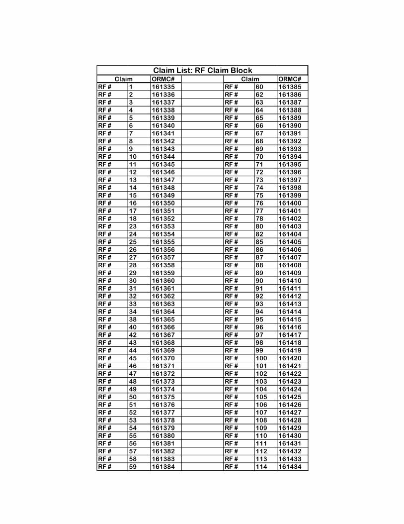
ORMC# ORMC#RF # 1 161335 RF # 60 161385RF # 2 161336 RF # 62 161386RF # 3 161337 RF # 63 161387RF # 4 161338 RF # 64 161388RF # 5 161339 RF # 65 161389RF # 6 161340 RF # 66 161390RF # 7 161341 RF # 67 161391RF # 8 161342 RF # 68 161392RF # 9 161343 RF # 69 161393RF # 10 161344 RF # 70 161394RF # 11 161345 RF # 71 161395RF # 12 161346 RF # 72 161396RF # 13 161347 RF # 73 161397RF # 14 161348 RF # 74 161398RF # 15 161349 RF # 75 161399RF # 16 161350 RF # 76 161400RF # 17 161351 RF # 77 161401RF # 18 161352 RF # 78 161402RF # 23 161353 RF # 80 161403RF # 24 161354 RF # 82 161404RF # 25 161355 RF # 85 161405RF # 26 161356 RF # 86 161406RF # 27 161357 RF # 87 161407RF # 28 161358 RF # 88 161408RF # 29 161359 RF # 89 161409RF # 30 161360 RF # 90 161410RF # 31 161361 RF # 91 161411RF # 32 161362 RF # 92 161412RF # 33 161363 RF # 93 161413RF # 34 161364 RF # 94 161414RF # 38 161365 RF # 95 161415RF # 40 161366 RF # 96 161416RF # 42 161367 RF # 97 161417RF # 43 161368 RF # 98 161418RF # 44 161369 RF # 99 161419RF # 45 161370 RF # 100 161420RF # 46 161371 RF # 101 161421RF # 47 161372 RF # 102 161422RF # 48 161373 RF # 103 161423RF # 49 161374 RF # 104 161424RF # 50 161375 RF # 105 161425RF # 51 161376 RF # 106 161426RF # 52 161377 RF # 107 161427RF # 53 161378 RF # 108 161428RF # 54 161379 RF # 109 161429RF # 55 161380 RF # 110 161430RF # 56 161381 RF # 111 161431RF # 57 161382 RF # 112 161432RF # 58 161383 RF # 113 161433RF # 59 161384 RF # 114 161434
Claim ClaimClaim List: RF Claim Block

APPENDIX B
Material Safety Data Sheets
Drill Additive

MATERIAL SAFETY DATA SHEET
BIO –CUT PLUS
Page 1 of 2
Product Identification
MANUFACTURER’S NAME: Control Chemical (1989) Corporation MANUFACTURER’S ADDRESS: 7016, 30th Street S.E. Calgary, Alberta, Canada T2C 1N9 EMERGENCY PHONE NUMBER: (403) 720-7044 SUPPLIER IDENTIFIER: SUPPLIER’S ADDRESS: SUPPLIER’S EMERGENCY PHONE NUMBER: PRODUCT IDENTIFIER: BIO-CUT PLUS PRODUCT USE:
Hazardous Ingredients of Materials Chemical Identity Concentration CAS#/NA#/UN# LD (50) LC (50) This is not a hazardous or controlled product.
Physical Data for Product PHYSICAL STATE: Liquid ODOUR AND APPEARANCE: Dark brown, distinctive ODOUR THRESHOLD: SPECIFIC GRAVITY: 0.887 VAPOR PRESSURE: Not established VAPOR DENSITY (Air = 1): Not established EVAPORATION RATE: Not established POILING POINT: >300 degrees C FREEZING POINT: -18 degrees C pH: 7.0 – 7.2 DENSITY (g/ml): COEFFICIENT OF WATER / OIL DISTRIBUTION: Not available
Fire and Explosion Hazard of Product CONDITIONS OF FLAMMABILITY: MEANS OF EXTINCTION: Foam, CO2, Dry chemical, water spray FLASHPOINT AND METHOD OF DETERMINATION: 290 degrees C C.C. UPPER EXPLOSION LIMIT (% by Vol): Not available LOWER EXPLOSION LIMIT (% by Vol): Not available AUTO-IGNITION TEMPERATURE: Not available FLAMMABILITY CLASSIFICATION: HAZARDOUS COMBUSTION PRODUCTS: Not available EXPLOSION DATA: Not available SENSITIVITY TO STATIC DISCHARGE: None
Reactivity Data CHEMICAL STABILITY: Stable INCOMPATIBLE MATERIALS: None CONDITIONS OF REACTIVITY: None HAZARDOUS DECOMPOSITION PRODUCTS: If burnt, oxides of sulphur

MATERIAL SAFETY DATA SHEET
BIO –CUT PLUS
Page 2 of 2
Toxicological Properties of Product ROUTES OF ENTRY: SKIN CONTACT: Wash with soap and water SKIN ABSORBTION: None EYE: Flush with water for 15 minutes INHALATION: No hazard during normal use INGESTION: Do not induce vomiting, contact physician. Not toxic. ACUTE OVER EXPOSURE EFFECTS: Inhalation: Not hazardous unless burning toxic fumes
possible. Ingestion: Greater than 5000 mg/kg in rats. Eyes: Eye irritation not expected. Skin: No skin irritation or allergic reaction expected.
CHRONIC OVER EXPOSURE EFFECTS: Inhalation: Not hazardous unless burning toxic fumes possible. Ingestion: Greater than 5000 mg/kg in rats. Eyes: Eye irritation not expected. Skin: No skin irritation or allergic reaction expected.
EXPOSURE LIMITS: Not available IRRITANCY OF PRODUCT: Not an irritant SENSITIZATION TO MATERIAL: None CARCINOGENICITY, REPRODUCTIVE EFFECTS: Not available TERATOGENICITY, MUTAGENICITY: Not available TOXICOLOGICALLY SYNERGISTIC PRODUCTS: Not available
Preventive Measures PERSONAL PROTECTIVE EQUIPMENT: Not necessary SPECIFIC ENGINEERING CONTROLS:
LEAK AND SPILL PROCEDURES: Although product is environmentally safe, spills should be contained and wiped up.
WASTE DISPOSAL: Although product is environmentally safe, spills should be contained and wiped up. Dispose according to Federal, Provincial or Municipal regulations. HANDLING PROCEDURES AND EQUIPMENT: None STORAGE REQUIREMENTS: None SPECIAL SHIPPING INFORMATION: Not Regulated.
First Aid Measures SPECIFIC FIRST AID PROCEDURES: Eyes: Flush with water for 15 minutes Ingestion: Do not induce vomiting, contact physician. Not toxic.
Skin: Wash with soap and water
Preparation Date of Material Safety Data Sheet PREPARED BY: Safety Committee PHONE NUMBER OF PREPARER: (403) 720-7044 DATE PREPARED: January 02, 2010 The information contained herein is based on data believed to be reliable, but is presented without guarantee or warranty and Control Chemical (1989) Corporation disclaims any liability incurred from the use thereof.

MATERIAL SAFETY DATA SHEET
DD 2000
Page 1 of 1
SECTION I – Product Identification
MANUFACTURER’S NAME: Control Chemical (1989) Corporation MANUFACTURER’S ADDRESS: 7016, 30th Street S.E. Calgary, Alberta, Canada T2C 1N9 EMERGENCY PHONE NUMBER: (403) 720-7044 SUPPLIER IDENTIFIER: SUPPLIER’S ADDRESS: SUPPLIER’S EMERGENCY PHONE NUMBER: PRODUCT IDENTIFIER: DD 2000 PRODUCT USE: Drilling mud – Co-polymer of Acrylamide and Sodium
Acrylate
SECTION II – Hazardous Ingredients of Materials Chemical Identity Concentration CAS#/NA#/UN# LD (50) LC (50) No regulated components. This is not a WHMIS controlled product.
SECTION III – Physical Data for Product PHYSICAL STATE: Solid ODOUR AND APPEARANCE: Granular white solid. Faint odour ODOUR THRESHOLD: Not available SPECIFIC GRAVITY: 0.80 VAPOR PRESSURE: Very low VAPOR DENSITY (Air = 1): Not available EVAPORATION RATE: Not available POILING POINT: Decomposes FREEZING POINT: Not available pH: Not available DENSITY (g/ml): 0.80 COEFFICIENT OF WATER / OIL DISTRIBUTION: Not available
SECTION IV – Fire and Explosion Hazard of Product CONDITIONS OF FLAMMABILITY: Requires a source of ignition, the presence of air, and a
temperature greater than the flash point. MEANS OF EXTINCTION: Use dry chemical, foam, or carbon dioxide. Water may
cause excessive slipperiness FLASHPOINT AND METHOD OF DETERMINATION: No flash point UPPER EXPLOSION LIMIT (% by Vol): Not available LOWER EXPLOSION LIMIT (% by Vol): Not available
MATERIAL SAFETY DATA SHEET
DD 2000
Page 2 of 2
AUTO-IGNITION TEMPERATURE: Not available FLAMMABILITY CLASSIFICATION: Not available. Not a controlled product. HAZARDOUS COMBUSTION PRODUCTS: Not available EXPLOSION DATA: Not available SENSITIVITY TO STATIC DISCHARGE: Not available
SECTION V – Reactivity Data CHEMICAL STABILITY: Stable under normal conditions. Hazardous polymerization will not occur INCOMPATIBLE MATERIALS: Avoid strong oxidizing and reducing agents. CONDITIONS OF REACTIVITY: Avoid contamination with reactive substances HAZARDOUS DECOMPOSITION PRODUCTS: Not available
SECTION VI – Toxicological Properties of Product ROUTES OF ENTRY:
SKIN CONTACT: No effects of exposure expected due to contact. Prolonged contact may cause skin irritation or dermatitis in some individuals.
SKIN ABSORBTION: No known hazard due to skin absorption EYE: No effects of exposure expected with the exception of possible irritation
INHALATION: May cause sneezing, slight irritation of nose and throat INGESTION: ACUTE OVER EXPOSURE EFFECTS: CHRONIC OVER EXPOSURE EFFECTS: Skin irritation or dermatitis may occur upon frequent or prolonged contact. EXPOSURE LIMITS: TWAEV = 0.03 mg/m3 (skin) (Ont. Reg. 654/86). IRRITANCY OF PRODUCT: Eye: mild irritant. SENSITIZATION TO MATERIAL: Repeated or prolonged contact may cause sensitization
in some individuals CARCINOGENICITY, REPRODUCTIVE EFFECTS: TERATOGENICITY, MUTAGENICITY: Not available TOXICOLOGICALLY SYNERGISTIC PRODUCTS: Not available
SECTION VII – Preventive Measures PERSONAL PROTECTIVE EQUIPMENT: Chemical goggles, impervious gloves, and protective
clothing as required to prevent contact. Use a mechanical-filter respirator as required to prevent exposure.
SPECIFIC ENGINEERING CONTROLS: General ventilation with a good source of make-up air recommended for all indoor situations
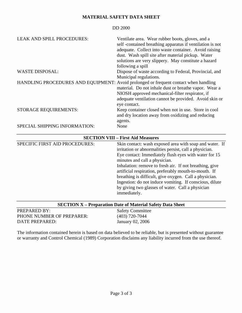
MATERIAL SAFETY DATA SHEET
DD 2000
Page 3 of 3
LEAK AND SPILL PROCEDURES: Ventilate area. Wear rubber boots, gloves, and a self -contained breathing apparatus if ventilation is not adequate. Collect into waste container. Avoid raising dust. Wash spill site after material pickup. Water solutions are very slippery. May constitute a hazard following a spill WASTE DISPOSAL: Dispose of waste according to Federal, Provincial, and Municipal regulations. HANDLING PROCEDURES AND EQUIPMENT: Avoid prolonged or frequent contact when handling material. Do not inhale dust or breathe vapor. Wear a NIOSH approved mechanical-filter respirator, if adequate ventilation cannot be provided. Avoid skin or eye contact. STORAGE REQUIREMENTS: Keep container closed when not in use. Store in cool and dry location away from oxidizing and reducing agents. SPECIAL SHIPPING INFORMATION: None
SECTION VIII – First Aid Measures SPECIFIC FIRST AID PROCEDURES: Skin contact: wash exposed area with soap and water. If
irritation or abnormalities persist, call a physician. Eye contact: Immediately flush eyes with water for 15 minutes and call a physician. Inhalation: remove to fresh air. If not breathing, give artificial respiration, preferably mouth-to-mouth. If breathing is difficult, give oxygen. Call a physician. Ingestion: do not induce vomiting. If conscious, dilute by giving two glasses of water. Call a physician immediately.
SECTION X – Preparation Date of Material Safety Data Sheet
PREPARED BY: Safety Committee PHONE NUMBER OF PREPARER: (403) 720-7044 DATE PREPARED: January 02, 2006 The information contained herein is based on data believed to be reliable, but is presented without guarantee or warranty and Control Chemical (1989) Corporation disclaims any liability incurred from the use thereof.