pjm merchant transmission request queue position … · pjm merchant transmission request queue...
TRANSCRIPT
Merchant Transmission Interconnection PJM Impact Study Report
For
PJM Merchant Transmission Request
Queue Position X3-028
Breed 345 kV
October/2014
© PJM Interconnection 2014. All rights reserved. 2 X3-028 System Impact Study Report
System Impact Study
Breed 345 kV Merchant Transmission Project
Introduction This System Impact Study report provides the documentation of an assessment that has been performed by PJM Interconnection, LLC and American Electric Power (AEP) in response to a request made by Clean Line Energy Partners LLC to evaluate the effects of proposed Grain Belt Express Clean Line. This is a proposed High Voltage Direct Current (HVDC) Transmission Line between Kansas and the AEP system in western Indiana. The System Impact Study evaluation was limited to the PJM footprint. MISO effects will be evaluated as part of the Facilities Process according to the Joint Operating Agreement (JOA) between PJM and MISO. As per the PJM study process, the X3-028 Project assessment was accomplished by: 1. Evaluating the reliability impact of the proposed facilities and connection on the interconnected transmission system by the performance of a power flow study; 2. Ensuring compliance with the NERC, ReliabilityFirst, PJM and AEP Reliability Standards by identifying the system reinforcements that will need to be installed for an interconnection of the proposed project; 3. Coordinating and cooperating with the PJM staff and AEP by participating in project meetings and issuing this report as a part of the PJM study process; 4. Performing a Steady State, Short-Circuit and Dynamics Study as necessary; 5. Conducting all studies in accordance with the PJM Manuals, the "AEP Requirements for Connecting to the Transmission System".
© PJM Interconnection 2014. All rights reserved. 3 X3-028 System Impact Study Report
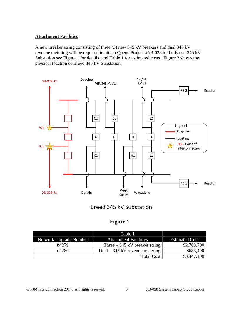
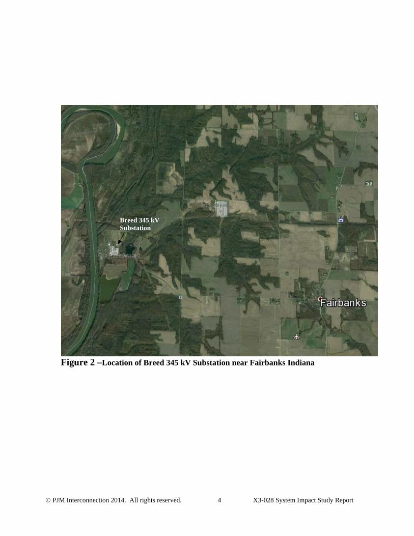
Attachment Facilities A new breaker string consisting of three (3) new 345 kV breakers and dual 345 kV revenue metering will be required to attach Queue Project #X3-028 to the Breed 345 kV Substation see Figure 1 for details, and Table 1 for estimated costs. Figure 2 shows the physical location of Breed 345 kV Substation.
J2
J
J1
H
H1
D2
D
C2
C
C1
X3-028 #2
X3-028 #1
Dequine
Darwin
765/345 kV #1765/345
kV #2
West Casey
Wheatland
Reactor
Reactor
Breed 345 kV Substation
POI
POI
RB 1
RB 2
Proposed
Existing
Legend
POI - Point of Interconnection
Figure 1
Table 1
Network Upgrade Number Attachment Facilities Estimated Cost n4279 Three – 345 kV breaker string $2,763,700n4280 Dual – 345 kV revenue metering $683,400
Total Cost $3,447,100
© PJM Interconnection 2014. All rights reserved. 4 X3-028 System Impact Study Report
Figure 2 –Location of Breed 345 kV Substation near Fairbanks Indiana
Breed 345 kV Substation
© PJM Interconnection 2014. All rights reserved. 5 X3-028 System Impact Study Report
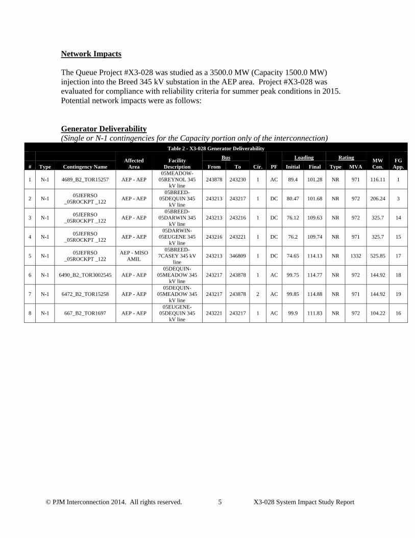
Network Impacts The Queue Project #X3-028 was studied as a 3500.0 MW (Capacity 1500.0 MW) injection into the Breed 345 kV substation in the AEP area. Project #X3-028 was evaluated for compliance with reliability criteria for summer peak conditions in 2015. Potential network impacts were as follows: Generator Deliverability (Single or N-1 contingencies for the Capacity portion only of the interconnection)
Table 2 - X3-028 Generator Deliverability
Affected
Area Facility
Description
Bus
Cir. PF
Loading Rating MW Con.
FG App. # Type Contingency Name From To Initial Final Type MVA
1 N-1 4689_B2_TOR15257 AEP - AEP 05MEADOW-
05REYNOL 345 kV line
243878 243230 1 AC 89.4 101.28 NR 971 116.11 1
2 N-1 05JEFRSO
_05ROCKPT _122 AEP - AEP
05BREED-05DEQUIN 345
kV line 243213 243217 1 DC 80.47 101.68 NR 972 206.24 3
3 N-1 05JEFRSO
_05ROCKPT _122 AEP - AEP
05BREED-05DARWIN 345
kV line 243213 243216 1 DC 76.12 109.63 NR 972 325.7 14
4 N-1 05JEFRSO
_05ROCKPT _122 AEP - AEP
05DARWIN-05EUGENE 345
kV line 243216 243221 1 DC 76.2 109.74 NR 971 325.7 15
5 N-1 05JEFRSO
_05ROCKPT _122 AEP - MISO
AMIL
05BREED-7CASEY 345 kV
line 243213 346809 1 DC 74.65 114.13 NR 1332 525.85 17
6 N-1 6490_B2_TOR3002545 AEP - AEP 05DEQUIN-
05MEADOW 345 kV line
243217 243878 1 AC 99.75 114.77 NR 972 144.92 18
7 N-1 6472_B2_TOR15258 AEP - AEP 05DEQUIN-
05MEADOW 345 kV line
243217 243878 2 AC 99.85 114.88 NR 971 144.92 19
8 N-1 667_B2_TOR1697 AEP - AEP 05EUGENE-
05DEQUIN 345 kV line
243221 243217 1 AC 99.9 111.83 NR 972 104.22 16
© PJM Interconnection 2014. All rights reserved. 6 X3-028 System Impact Study Report
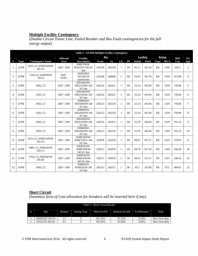
Multiple Facility Contingency (Double Circuit Tower Line, Failed Breaker and Bus Fault contingencies for the full energy output)
Table 3 - X3-028 Multiple Facility Contingency
Affected Area
Facility Description
Bus
Cir. PF
Loading Rating MW Con.
FG App. # Type Contingency Name From To Initial Final Type MVA
1 LFFB 6523_C2_05MEADOW
345-A1 AEP - AEP
05REYNOL-05OLIVE 345 kV
line 243230 243229 1 DC 81.17 101.56 ER 1195 243.7 2
2 LFFB 1760_C2_05JEFRSO
765-A AEP - OVEC
05JEFRSO 765/345 kV transformer
243208 248000 1 DC 54.55 101.78 ER 1935 913.89 4
3 LFFB 3002_C2 AEP - AEP 05DARWIN-
05EUGENE 345 kV line
243216 243221 1 DC 52.14 105.69 ER 1419 759.96 5
4 LFFB 3183_C2 AEP - AEP 05DARWIN-
05EUGENE 345 kV line
243216 243221 1 DC 52.14 105.69 ER 1419 759.96 6
5 LFFB 3002_C2 AEP - AEP 05BREED-
05DARWIN 345 kV line
243213 243216 1 DC 52.14 105.69 ER 1419 759.96 7
6 LFFB 3183_C2 AEP - AEP 05BREED-
05DARWIN 345 kV line
243213 243216 1 DC 52.14 105.69 ER 1419 759.96 8
7 LFFB 2930_C2 AEP - AEP 05DARWIN-
05EUGENE 345 kV line
243216 243221 1 DC 52.79 106.44 ER 1419 761.25 9
8 LFFB 2930_C2 AEP - AEP 05BREED-
05DARWIN 345 kV line
243213 243216 1 DC 52.79 106.44 ER 1419 761.25 10
9 LFFB 6523_C2_05MEADOW
345-A1 AEP - AEP
05MEADOW-05REYNOL 345
kV line 243878 243230 1 DC 88.07 107.17 ER 1419 270.93 11
10 LFFB 6485_C2_05DEQUIN
345-C1 AEP - AEP
05DEQUIN-05MEADOW 345 kV line
243217 243878 1 AC 94.78 121.18 ER 1304 344.26 20
11 LFFB 4704_C2_05DEQUIN
345-B1 AEP - AEP
05DEQUIN-05MEADOW 345 kV line
243217 243878 2 AC 98.32 125.71 ER 1257 344.26 22
12 LFFB 2930_C2 AEP - AEP 05BREED-
05DEQUIN 345 kV line
243213 243217 1 DC 83.1 132.96 ER 972 484.61 23
Short Circuit (Summary form of Cost allocation for breakers will be inserted here if any)
Table 4 - Short Circuit Results
# Bus Breaker Rating Type With X3-028 Without X3-028 % Difference Note
1 05BREED 345.kV C1 T 105.10% 93.10% 12.00% New Over-duty 2 05OLIVE 345.kV E1 T 102.50% 97.90% 4.60% New Over-duty
© PJM Interconnection 2014. All rights reserved. 7 X3-028 System Impact Study Report
1. AEP submitted a Supplemental Project to completely rebuild the Breed 345 kV station. The Breed station rebuild will utilize new 63 kA breakers.
2. Olive CB E1 was replaced with a 63 kA breaker in 2012
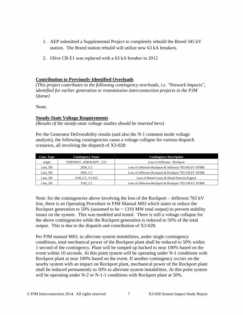
Contribution to Previously Identified Overloads (This project contributes to the following contingency overloads, i.e. "Network Impacts", identified for earlier generation or transmission interconnection projects in the PJM Queue) None. Steady-State Voltage Requirements (Results of the steady-state voltage studies should be inserted here) Per the Generator Deliverability results (and also the N-1 common mode voltage analysis), the following contingencies cause a voltage collapse for various dispatch scenarios, all involving the dispatch of X3-028:
Cont. Type Contingency Name Contingency Description
single '05JEFRSO _05ROCKPT _122' Loss of Jefferson - Rockport
Line_FB 2930_C2 Loss of Jefferson-Rockport & Jefferson 765/345 kV XFMR
Line_FB 3002_C2 Loss of Jefferson-Rockport & Rockport 765/138 kV XFMR
Line_FB 3106_C2_V3-032 Loss of Breed-Casey & Breed-Darwin-Eugene
Line_FB 3183_C2 Loss of Jefferson-Rockport & Rockport 765/138 kV XFMR
Note: for the contingencies above involving the loss of the Rockport – Jefferson 765 kV line, there is an Operating Procedure in PJM Manual M03 which states to reduce the Rockport generation to 50% (assumed to be ~ 1310 MW total output) to prevent stability issues on the system. This was modeled and tested. There is still a voltage collapse for the above contingencies while the Rockport generation is reduced to 50% of the total output. This is due to the dispatch and contribution of X3-028. Per PJM manual M03, to alleviate system instabilities, under single contingency conditions, total mechanical power of the Rockport plant shall be reduced to 50% within 1 second of the contingency. Plant will be ramped up backed to near 100% based on the event within 10 seconds. At this point system will be operating under N-1 conditions with Rockport plant at near 100% based on the event. If another contingency occurs on the nearby system with an impact on Rockport plant, mechanical power of the Rockport plant shall be reduced permanently to 50% to alleviate system instabilities. At this point system will be operating under N-2 or N-1-1 conditions with Rockport plant at 50%.
© PJM Interconnection 2014. All rights reserved. 8 X3-028 System Impact Study Report
N-1-1 Analysis No violations identified. MISO Impacts To be determined in the Facilities Study. Light Load Analysis
The following facilities were identified as potential constraints in the light load analysis:
Breed-Wheatland 345 kV, maximum loading 124.5% for a single contingency, 122.1 % for a breaker contingency
Eugene-Cayuga Sub 345 kV, maximum loading 107.3% for a single contingency, 105.2 % for a breaker contingency
Cayuga Sub – Cayuga 345 kV, maximum loading 105.1% for a single contingency, 103.1 % for a breaker contingency
As the first two constraints are PJM-MISO tie lines, and the third is a MISO internal facility, these results are preliminary, and will be reviewed and finalized as part of the PJM-MISO coordination during the Facilities Study.
Stability and Reactive Power Requirement (Results of the dynamic studies should be inserted here)
The stability analysis performed to date also identifies that the Pioneer project upgrades are necessary. However, even with inclusion of the reinforcements identified to mitigate steady-state needs, X3-028 failed to meet criteria for a number of studied contingencies summarized below:
For several contingencies the X3-028 HVDC circuits are disconnected from the system (permanently blocked) prior to fault clearing or mid-simulation.
The addition of the X3-028 HVDC line causes the Fowler Ridge and Meadow Lake wind farms to trip for several contingencies.
X3-028 HVDC circuits were manually deblocked (post fault clearing) for the contingencies which caused the DC line to disconnect prior to fault clearing. Tripping of the Fowler Ridge and Meadow Lake wind farms still occurs.
Blocking of X3-028 was able to be resolved for some contingencies through the addition of dynamic compensation of approximately +800 MVAr and -1000
© PJM Interconnection 2014. All rights reserved. 9 X3-028 System Impact Study Report
MVAr. However, dynamic compensation was not sufficient to consistently eliminate the blocking for contingencies involving the Rockport – Jefferson 765 kV circuit.
As X3-028 is required to stay connected to the system for all faults, an updated model that exhibits this behavior is needed. The results suggest that further transmission reinforcement may also be required; the extent of this reinforcement cannot be identified prior to an updated X3-028 dynamic model being available. The full Stability report is attached at the end of the System Impact report.
New System Reinforcements (Upgrades required to mitigate reliability criteria violations, i.e. Network Impacts, initially caused by the addition of this project generation)
1. Per the dynamic model provided for X3-028, there will be 9 banks of 275 MVAR per bank totaling 2475 MVAR connected to the Breed end of the DC line. Per the dynamic simulation, 8 of the 9 banks are on to support the HVDC converters, leaving 1 bank of 275 MVAR available for net injection into the PJM system at Breed. This 275 MVAR injection into Breed was assumed available for all voltage studies.
2. PJM 2018 base line upgrade B2287 to loop the Meadowlake – Olive 345 kV line into Reynolds 345 kV. The expected cost responsibility for X3-028 is $0.
3. MISO approved 345 kV MVP project to build a new Reynolds – Bur Oak – Hiple 345 kV line. This project is expected to be in-service in 2018. The expected cost responsibility for X3-028 is $0.
4. A segment of the MISO approved Pioneer project to build a new Reynolds – Greentown 765 kV line as well as a 765/345 kV transformer at Reynolds. This project is expected to be in-service in 2018. The cost for this project is estimated to be $270 M. The expected cost responsibility for X3-028 is $0.
5. A segment of the MISO (unapproved) Pioneer project to build a new Sullivan - Reynolds 765 kV line. The cost for this project is estimated to be $500 M. The expected cost responsibility for X3-028 is $500 M. It would take Pioneer LLC (3) three to (4) four years to build this section of the 765 kV line from the time CSA is signed.
Sullivan – Reynolds 765 kV line: $480 million Work at Sullivan Station: $10 million Work at Reynolds Station: $10 million Total Cost: $500 million
With the 5 New System Reinforcements modeled above, all reliability violations are resolved except for the following, which still need to be addressed:
© PJM Interconnection 2014. All rights reserved. 10 X3-028 System Impact Study Report
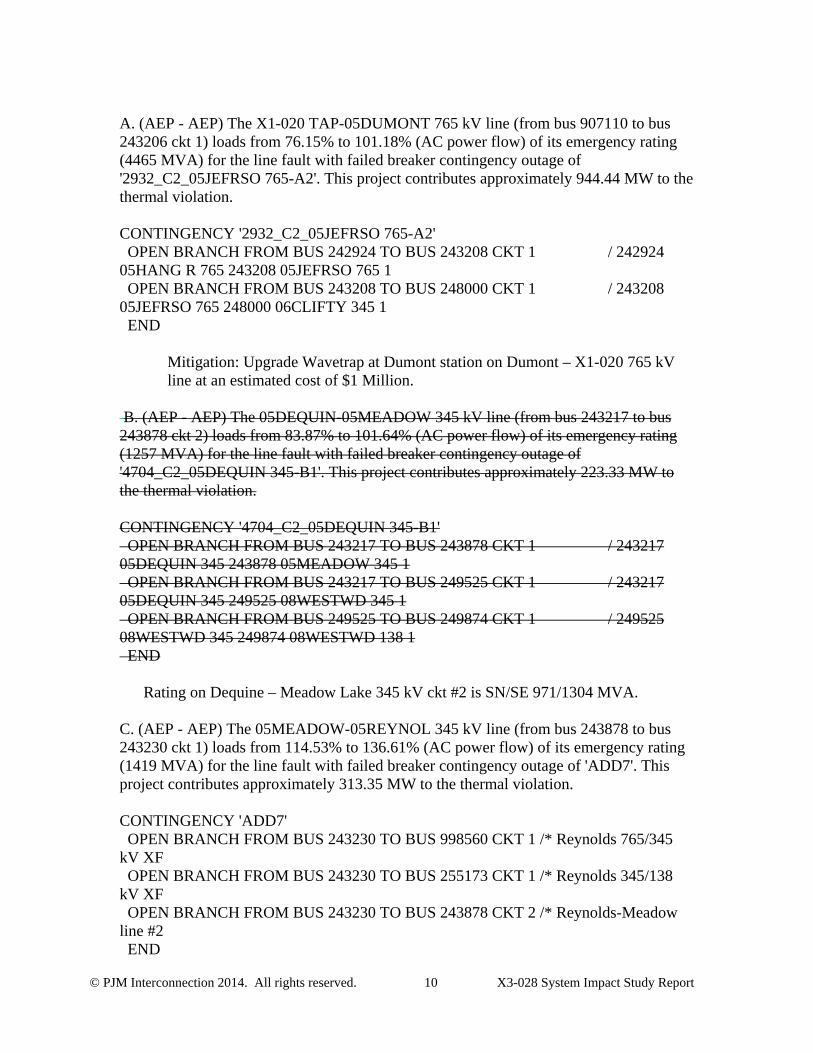
A. (AEP - AEP) The X1-020 TAP-05DUMONT 765 kV line (from bus 907110 to bus 243206 ckt 1) loads from 76.15% to 101.18% (AC power flow) of its emergency rating (4465 MVA) for the line fault with failed breaker contingency outage of '2932_C2_05JEFRSO 765-A2'. This project contributes approximately 944.44 MW to the thermal violation. CONTINGENCY '2932_C2_05JEFRSO 765-A2' OPEN BRANCH FROM BUS 242924 TO BUS 243208 CKT 1 / 242924 05HANG R 765 243208 05JEFRSO 765 1 OPEN BRANCH FROM BUS 243208 TO BUS 248000 CKT 1 / 243208 05JEFRSO 765 248000 06CLIFTY 345 1 END
Mitigation: Upgrade Wavetrap at Dumont station on Dumont – X1-020 765 kV line at an estimated cost of $1 Million.
B. (AEP - AEP) The 05DEQUIN-05MEADOW 345 kV line (from bus 243217 to bus 243878 ckt 2) loads from 83.87% to 101.64% (AC power flow) of its emergency rating (1257 MVA) for the line fault with failed breaker contingency outage of '4704_C2_05DEQUIN 345-B1'. This project contributes approximately 223.33 MW to the thermal violation. CONTINGENCY '4704_C2_05DEQUIN 345-B1' OPEN BRANCH FROM BUS 243217 TO BUS 243878 CKT 1 / 243217 05DEQUIN 345 243878 05MEADOW 345 1 OPEN BRANCH FROM BUS 243217 TO BUS 249525 CKT 1 / 243217 05DEQUIN 345 249525 08WESTWD 345 1 OPEN BRANCH FROM BUS 249525 TO BUS 249874 CKT 1 / 249525 08WESTWD 345 249874 08WESTWD 138 1 END
Rating on Dequine – Meadow Lake 345 kV ckt #2 is SN/SE 971/1304 MVA.
C. (AEP - AEP) The 05MEADOW-05REYNOL 345 kV line (from bus 243878 to bus 243230 ckt 1) loads from 114.53% to 136.61% (AC power flow) of its emergency rating (1419 MVA) for the line fault with failed breaker contingency outage of 'ADD7'. This project contributes approximately 313.35 MW to the thermal violation. CONTINGENCY 'ADD7' OPEN BRANCH FROM BUS 243230 TO BUS 998560 CKT 1 /* Reynolds 765/345 kV XF OPEN BRANCH FROM BUS 243230 TO BUS 255173 CKT 1 /* Reynolds 345/138 kV XF OPEN BRANCH FROM BUS 243230 TO BUS 243878 CKT 2 /* Reynolds-Meadow line #2 END
© PJM Interconnection 2014. All rights reserved. 11 X3-028 System Impact Study Report
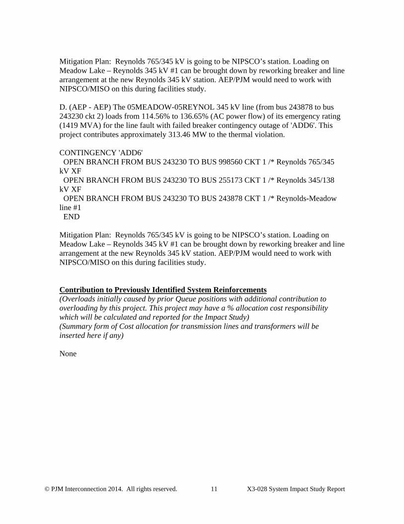
Mitigation Plan: Reynolds 765/345 kV is going to be NIPSCO’s station. Loading on Meadow Lake – Reynolds 345 kV #1 can be brought down by reworking breaker and line arrangement at the new Reynolds 345 kV station. AEP/PJM would need to work with NIPSCO/MISO on this during facilities study. D. (AEP - AEP) The 05MEADOW-05REYNOL 345 kV line (from bus 243878 to bus 243230 ckt 2) loads from 114.56% to 136.65% (AC power flow) of its emergency rating (1419 MVA) for the line fault with failed breaker contingency outage of 'ADD6'. This project contributes approximately 313.46 MW to the thermal violation. CONTINGENCY 'ADD6' OPEN BRANCH FROM BUS 243230 TO BUS 998560 CKT 1 /* Reynolds 765/345 kV XF OPEN BRANCH FROM BUS 243230 TO BUS 255173 CKT 1 /* Reynolds 345/138 kV XF OPEN BRANCH FROM BUS 243230 TO BUS 243878 CKT 1 /* Reynolds-Meadow line #1 END Mitigation Plan: Reynolds 765/345 kV is going to be NIPSCO’s station. Loading on Meadow Lake – Reynolds 345 kV #1 can be brought down by reworking breaker and line arrangement at the new Reynolds 345 kV station. AEP/PJM would need to work with NIPSCO/MISO on this during facilities study. Contribution to Previously Identified System Reinforcements (Overloads initially caused by prior Queue positions with additional contribution to overloading by this project. This project may have a % allocation cost responsibility which will be calculated and reported for the Impact Study) (Summary form of Cost allocation for transmission lines and transformers will be inserted here if any) None
© PJM Interconnection 2014. All rights reserved. 12 X3-028 System Impact Study Report
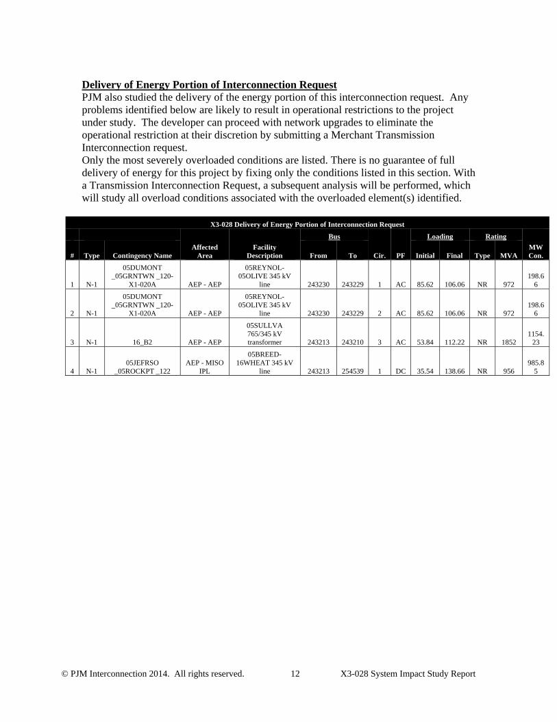
Delivery of Energy Portion of Interconnection Request PJM also studied the delivery of the energy portion of this interconnection request. Any problems identified below are likely to result in operational restrictions to the project under study. The developer can proceed with network upgrades to eliminate the operational restriction at their discretion by submitting a Merchant Transmission Interconnection request. Only the most severely overloaded conditions are listed. There is no guarantee of full delivery of energy for this project by fixing only the conditions listed in this section. With a Transmission Interconnection Request, a subsequent analysis will be performed, which will study all overload conditions associated with the overloaded element(s) identified.
X3-028 Delivery of Energy Portion of Interconnection Request
Affected Area
Facility Description
Bus
Cir. PF
Loading Rating
MW Con. # Type Contingency Name From To Initial Final Type MVA
1 N-1
05DUMONT _05GRNTWN _120-
X1-020A AEP - AEP
05REYNOL-05OLIVE 345 kV
line 243230 243229 1 AC 85.62 106.06 NR 972 198.6
6
2 N-1
05DUMONT _05GRNTWN _120-
X1-020A AEP - AEP
05REYNOL-05OLIVE 345 kV
line 243230 243229 2 AC 85.62 106.06 NR 972 198.6
6
3 N-1 16_B2 AEP - AEP
05SULLVA 765/345 kV transformer 243213 243210 3 AC 53.84 112.22 NR 1852
1154.23
4 N-1 05JEFRSO
_05ROCKPT _122 AEP - MISO
IPL
05BREED-16WHEAT 345 kV
line 243213 254539 1 DC 35.54 138.66 NR 956 985.8
5
© PJM Interconnection 2014. All rights reserved. 13 X3-028 System Impact Study Report
Stability Study Report
ExecutiveSummaryPJM Queue Project X3-028 is an HVDC Merchant Transmission Interconnection Request for 3500 MW (Maximum Facility Output) connecting to Breed 345 kV substation in the American Electric Power (AEP) system. This report describes the dynamic simulation analysis of X3-028 as part of the overall system impact study.
The load flow scenario for this analysis was based on the RTEP 2017 light load case, modified to include applicable queue projects. The case also takes into account the entire proposed Pioneer Project, identified as required by the loadflow analysis.
X3-028 was tested for compliance with NERC, PJM and other applicable criteria. 112 fault contingencies were studied. The studied faults include:
a) Steady state operation
b) Three phase faults with normal clearing time
c) Three phase faults with loss of multiple-circuit tower line
d) Single phase bus faults with normal clearing time
e) Single phase faults with single phase stuck breaker
f) Single phase faults with delayed clearing at remote end due to primary relaying failure
g) Three phase faults under outages.
For all the simulated faults, the queue project under study along with the rest of the PJM system were required to maintain synchronism and have all states returning to an acceptable new condition following the disturbance.
For a number of the studied contingencies, X3-028 failed to meet criteria:
For several contingencies the X3-028 HVDC circuits are disconnected from the system (permanently blocked) prior to fault clearing or mid-simulation.
The addition of the X3-028 HVDC line causes the Fowler Ridge and Meadow Lake wind farms to trip for several contingencies.
X3-028 HVDC circuits were manually deblocked (post fault clearing) for the contingencies which caused the DC line to disconnect prior to fault clearing. Tripping of the Fowler Ridge and Meadow Lake wind farms still occurs.
Blocking of X3-028 was able to be resolved for some contingencies through the addition of dynamic compensation of approximately +800 MVAr and -1000 MVAr. However, dynamic compensation was not sufficient to consistently eliminate the blocking for contingencies involving the Rockport – Jefferson 765 kV circuit.
As X3-028 is required to stay connected to the system for all faults, an updated model that exhibits this behavior is needed. The results suggest that further transmission reinforcement may also be required; the extent of this reinforcement cannot be confirmed prior to an updated X3-028 dynamic model being available.
© PJM Interconnection 2014. All rights reserved. 14 X3-028 System Impact Study Report
1. IntroductionGeneration Interconnection Request X3-028 is for the interconnection of two 1750 MW 600 kV HVDC circuits (configured as a 3500 MW, +/- 600 kV bipole) from southwestern Kansas into the American Electric Power (AEP) network in Western Indiana.
PJM contracted Power Systems Consultants (PSC) to carry out this dynamic simulation analysis of X3-028 as part of the overall system impact study. This analysis is effectively a screening study to determine whether the addition of X3-028 will meet the dynamics requirements of the NERC and PJM reliability standards.
In this report, the X3-028 queue project and how it is proposed to be connected to the grid are first described, followed by a description of how the project is modeled in this study. The fault cases are then described and analyzed, and lastly a discussion of the results is provided.
2. DescriptionofProjectThe proposed X3-028 queue project consists of two 1750 MW, 600 kV DC transmission lines that connect the SPP system to the PJM system at Breed 345 kV (POI) in the AEP network.
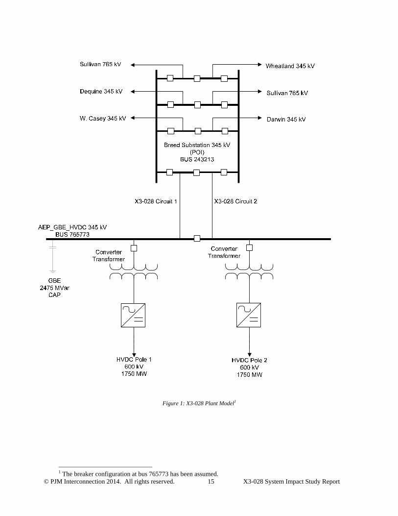
Figure 1 shows how X3-028 has been modeled in this study at the PJM end. Table 1 lists the parameters given in the Impact Study Data Form and the corresponding parameters of the X3-028 loadflow model.
Additional X3-028 project details are provided in Attachments 1 through 5:
Attachment 1 contains the Impact Study data;
Attachment 2 shows the one-line diagram of the AEP network in the vicinity of X3-028;
Attachment 3 provides a diagram of the PSS/E model in the vicinity of X3-028;
Attachment 4 gives the X3-028 PSS/E loadflow model – this includes the complete project including the wind generation located in the SPP system; and
Attachment 5 contains the dynamic models for the X3-028. These are based on user models supplied to PJM by the developer.
© PJM Interconnection 2014. All rights reserved. 15 X3-028 System Impact Study Report
Figure 1: X3-028 Plant Model1
1 The breaker configuration at bus 765773 has been assumed.
© PJM Interconnection 2014. All rights reserved. 16 X3-028 System Impact Study Report
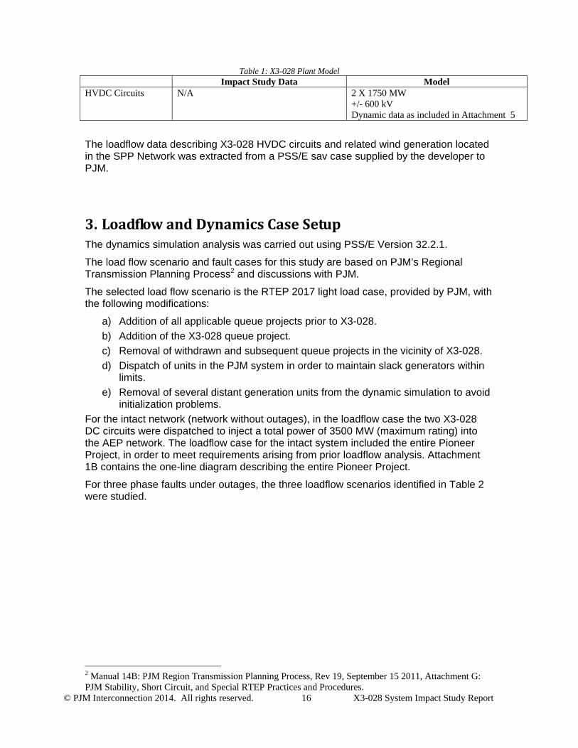
Table 1: X3-028 Plant Model Impact Study Data Model
HVDC Circuits N/A
2 X 1750 MW +/- 600 kV Dynamic data as included in Attachment 5
The loadflow data describing X3-028 HVDC circuits and related wind generation located in the SPP Network was extracted from a PSS/E sav case supplied by the developer to PJM.
3. LoadflowandDynamicsCaseSetupThe dynamics simulation analysis was carried out using PSS/E Version 32.2.1.
The load flow scenario and fault cases for this study are based on PJM’s Regional Transmission Planning Process2 and discussions with PJM.
The selected load flow scenario is the RTEP 2017 light load case, provided by PJM, with the following modifications:
a) Addition of all applicable queue projects prior to X3-028.
b) Addition of the X3-028 queue project.
c) Removal of withdrawn and subsequent queue projects in the vicinity of X3-028.
d) Dispatch of units in the PJM system in order to maintain slack generators within limits.
e) Removal of several distant generation units from the dynamic simulation to avoid initialization problems.
For the intact network (network without outages), in the loadflow case the two X3-028 DC circuits were dispatched to inject a total power of 3500 MW (maximum rating) into the AEP network. The loadflow case for the intact system included the entire Pioneer Project, in order to meet requirements arising from prior loadflow analysis. Attachment 1B contains the one-line diagram describing the entire Pioneer Project.
For three phase faults under outages, the three loadflow scenarios identified in Table 2 were studied.
2 Manual 14B: PJM Region Transmission Planning Process, Rev 19, September 15 2011, Attachment G: PJM Stability, Short Circuit, and Special RTEP Practices and Procedures.
© PJM Interconnection 2014. All rights reserved. 17 X3-028 System Impact Study Report
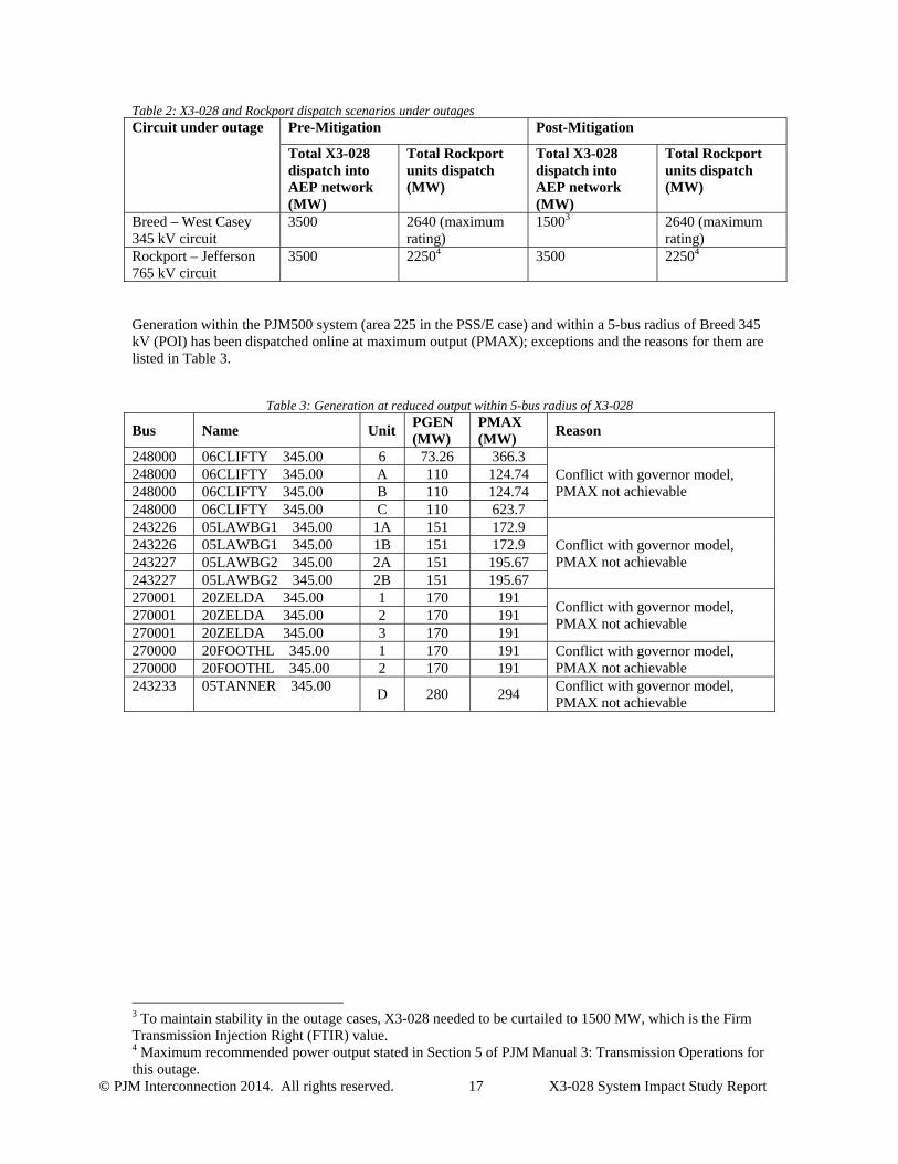
Table 2: X3-028 and Rockport dispatch scenarios under outages Circuit under outage Pre-Mitigation Post-Mitigation
Total X3-028 dispatch into AEP network (MW)
Total Rockport units dispatch (MW)
Total X3-028 dispatch into AEP network (MW)
Total Rockport units dispatch (MW)
Breed – West Casey 345 kV circuit
3500 2640 (maximum rating)
15003 2640 (maximum rating)
Rockport – Jefferson 765 kV circuit
3500 22504 3500 22504
Generation within the PJM500 system (area 225 in the PSS/E case) and within a 5-bus radius of Breed 345 kV (POI) has been dispatched online at maximum output (PMAX); exceptions and the reasons for them are listed in Table 3.
Table 3: Generation at reduced output within 5-bus radius of X3-028
Bus Name Unit PGEN (MW)
PMAX (MW)
Reason
248000 06CLIFTY 345.00 6 73.26 366.3 Conflict with governor model, PMAX not achievable
248000 06CLIFTY 345.00 A 110 124.74 248000 06CLIFTY 345.00 B 110 124.74 248000 06CLIFTY 345.00 C 110 623.7 243226 05LAWBG1 345.00 1A 151 172.9
Conflict with governor model, PMAX not achievable
243226 05LAWBG1 345.00 1B 151 172.9 243227 05LAWBG2 345.00 2A 151 195.67 243227 05LAWBG2 345.00 2B 151 195.67 270001 20ZELDA 345.00 1 170 191
Conflict with governor model, PMAX not achievable
270001 20ZELDA 345.00 2 170 191 270001 20ZELDA 345.00 3 170 191 270000 20FOOTHL 345.00 1 170 191 Conflict with governor model,
PMAX not achievable 270000 20FOOTHL 345.00 2 170 191 243233 05TANNER 345.00
D 280 294 Conflict with governor model, PMAX not achievable
3 To maintain stability in the outage cases, X3-028 needed to be curtailed to 1500 MW, which is the Firm Transmission Injection Right (FTIR) value. 4 Maximum recommended power output stated in Section 5 of PJM Manual 3: Transmission Operations for this outage.
© PJM Interconnection 2014. All rights reserved. 18 X3-028 System Impact Study Report
4. FaultCasesTable 6 to Table 12 list the contingencies that were studied, with representative worst case total clearing times provided by PJM. Each contingency was studied over a 10 second simulation time interval. Faults were applied to transmission circuits and transformers connected to the Point of Interconnection or one bus removed5 (up to two buses removed for delayed (Zone 2) clearing faults).
The studied faults included :
a) Steady state operation
b) Three phase faults with normal clearing time
c) Three phase faults with loss of multiple-circuit tower line
d) Single phase bus faults with normal clearing time
e) Single phase faults with single phase stuck breaker
f) Single phase faults with delayed clearing at remote end due to primary relaying failure
g) Three phase faults under outages
The one line diagram of the AEP network in Attachment 2 shows where faults were applied.
The positive sequence fault impedances for single line to ground faults were derived from a separate short circuit case provided by PJM, updated by PSC to reflect latest system configuration, active queue projects and updates to X3-028 models. . Attachment 7 gives the positive sequence fault impedances for single-line to ground faults.
5. EvaluationCriteriaThis study is focused on the queue project, along with the rest of the PJM system, maintaining synchronism and having all states return to an acceptable new condition following the disturbance. The recovery criteria applicable to this study are as per the PJM Region Transmission Planning Process:
a) System transient stability should be maintained. b) The X3-028 DC circuits should maintain their pre-contingent power injection into
the POI following the fault. c) Post-contingency oscillations should be positively damped with a damping
margin of at least 3%. d) Post-contingency voltages should remain within +/- 0.05 pu of the pre-
contingency voltages at transmission level buses.
5 One bus removed from the POI refers to buses with transmission circuit breakers, not tee-offs or buses with only supply circuit breakers.
© PJM Interconnection 2014. All rights reserved. 19 X3-028 System Impact Study Report
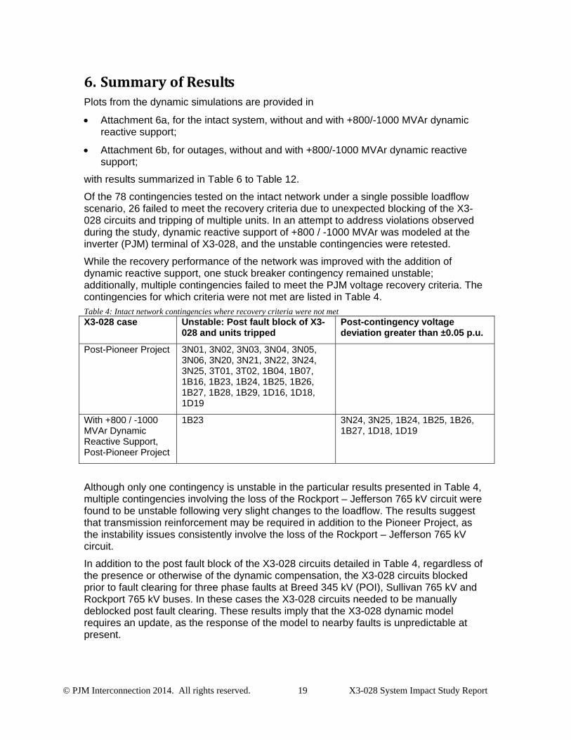
6. SummaryofResultsPlots from the dynamic simulations are provided in
Attachment 6a, for the intact system, without and with +800/-1000 MVAr dynamic reactive support;
Attachment 6b, for outages, without and with +800/-1000 MVAr dynamic reactive support;
with results summarized in Table 6 to Table 12.
Of the 78 contingencies tested on the intact network under a single possible loadflow scenario, 26 failed to meet the recovery criteria due to unexpected blocking of the X3-028 circuits and tripping of multiple units. In an attempt to address violations observed during the study, dynamic reactive support of +800 / -1000 MVAr was modeled at the inverter (PJM) terminal of X3-028, and the unstable contingencies were retested.
While the recovery performance of the network was improved with the addition of dynamic reactive support, one stuck breaker contingency remained unstable; additionally, multiple contingencies failed to meet the PJM voltage recovery criteria. The contingencies for which criteria were not met are listed in Table 4. Table 4: Intact network contingencies where recovery criteria were not met X3-028 case Unstable: Post fault block of X3-
028 and units tripped Post-contingency voltage deviation greater than ±0.05 p.u.
Post-Pioneer Project 3N01, 3N02, 3N03, 3N04, 3N05, 3N06, 3N20, 3N21, 3N22, 3N24, 3N25, 3T01, 3T02, 1B04, 1B07, 1B16, 1B23, 1B24, 1B25, 1B26, 1B27, 1B28, 1B29, 1D16, 1D18, 1D19
With +800 / -1000 MVAr Dynamic Reactive Support, Post-Pioneer Project
1B23 3N24, 3N25, 1B24, 1B25, 1B26, 1B27, 1D18, 1D19
Although only one contingency is unstable in the particular results presented in Table 4, multiple contingencies involving the loss of the Rockport – Jefferson 765 kV circuit were found to be unstable following very slight changes to the loadflow. The results suggest that transmission reinforcement may be required in addition to the Pioneer Project, as the instability issues consistently involve the loss of the Rockport – Jefferson 765 kV circuit.
In addition to the post fault block of the X3-028 circuits detailed in Table 4, regardless of the presence or otherwise of the dynamic compensation, the X3-028 circuits blocked prior to fault clearing for three phase faults at Breed 345 kV (POI), Sullivan 765 kV and Rockport 765 kV buses. In these cases the X3-028 circuits needed to be manually deblocked post fault clearing. These results imply that the X3-028 dynamic model requires an update, as the response of the model to nearby faults is unpredictable at present.
© PJM Interconnection 2014. All rights reserved. 20 X3-028 System Impact Study Report
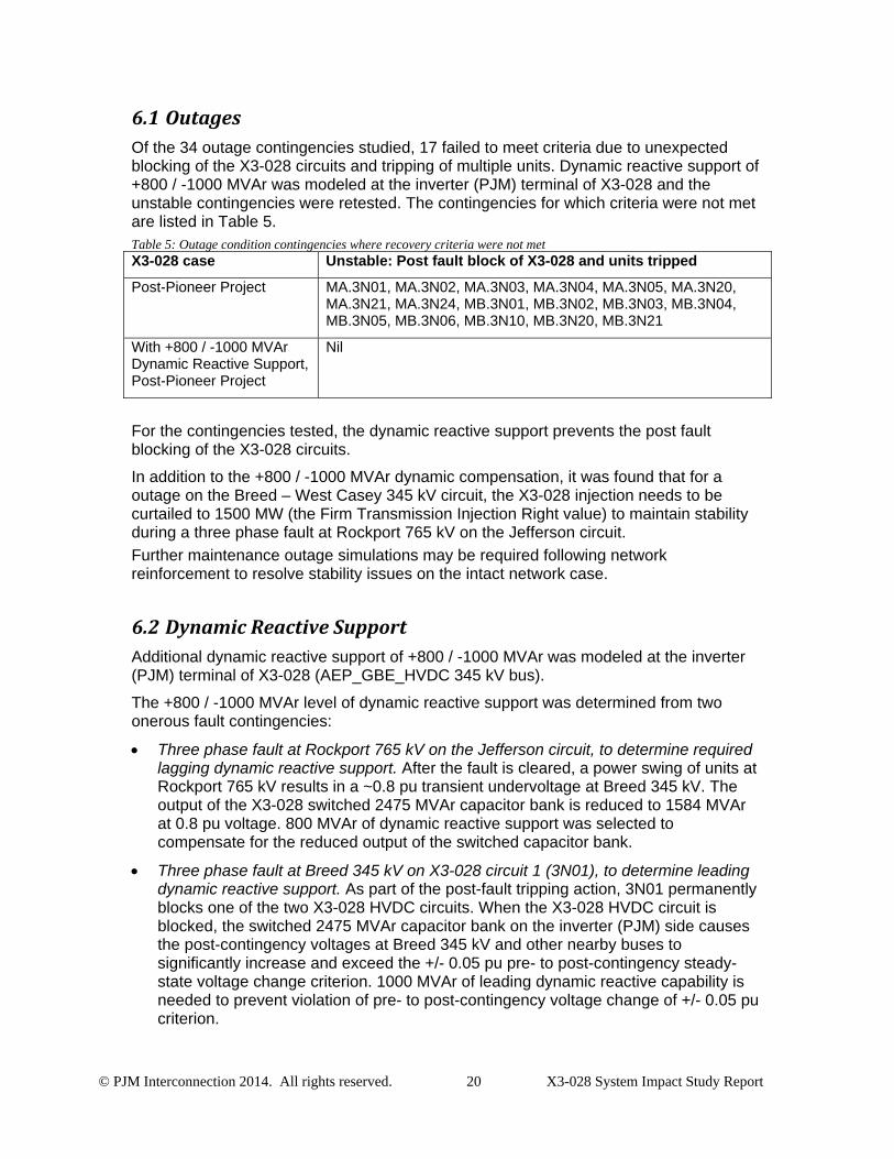
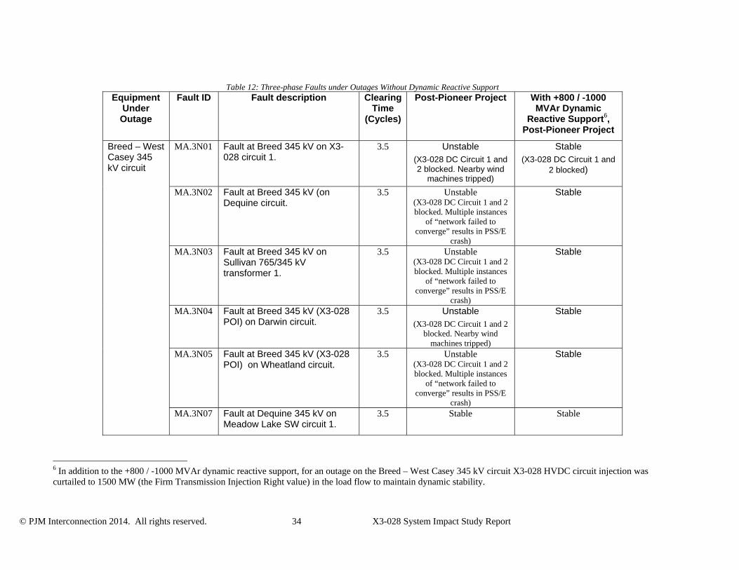
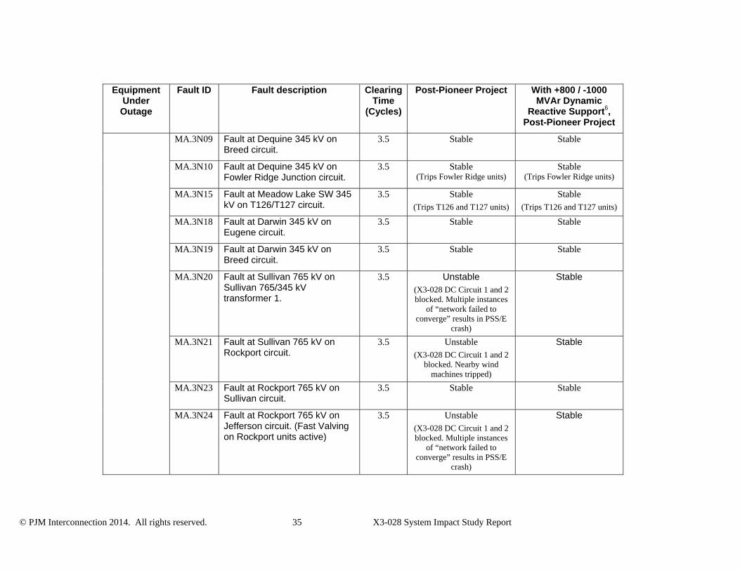
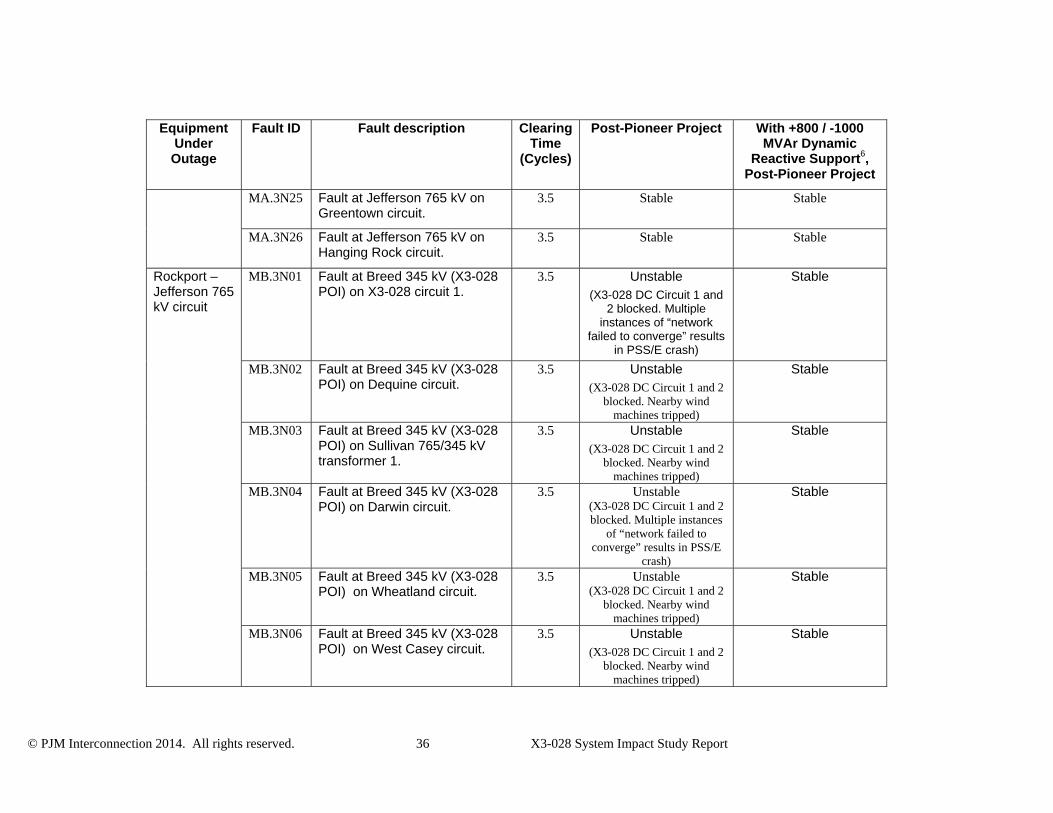
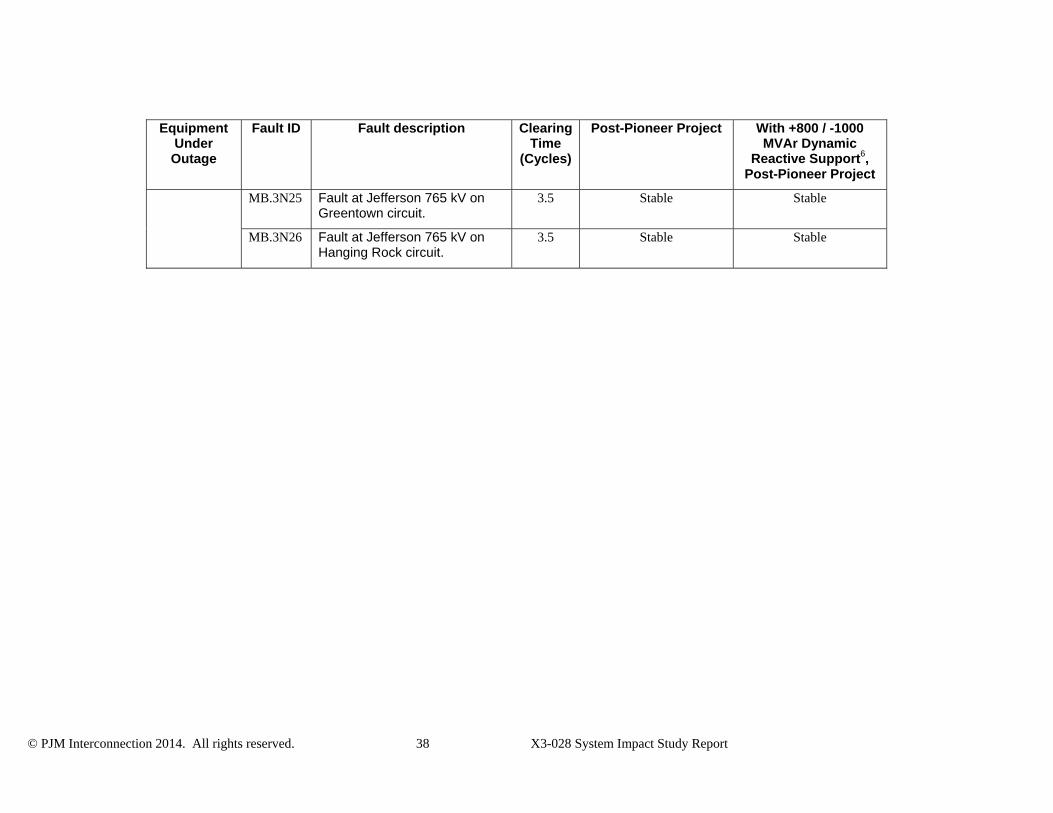
6.1 OutagesOf the 34 outage contingencies studied, 17 failed to meet criteria due to unexpected blocking of the X3-028 circuits and tripping of multiple units. Dynamic reactive support of +800 / -1000 MVAr was modeled at the inverter (PJM) terminal of X3-028 and the unstable contingencies were retested. The contingencies for which criteria were not met are listed in Table 5. Table 5: Outage condition contingencies where recovery criteria were not met X3-028 case Unstable: Post fault block of X3-028 and units tripped
Post-Pioneer Project MA.3N01, MA.3N02, MA.3N03, MA.3N04, MA.3N05, MA.3N20, MA.3N21, MA.3N24, MB.3N01, MB.3N02, MB.3N03, MB.3N04, MB.3N05, MB.3N06, MB.3N10, MB.3N20, MB.3N21
With +800 / -1000 MVAr Dynamic Reactive Support, Post-Pioneer Project
Nil
For the contingencies tested, the dynamic reactive support prevents the post fault blocking of the X3-028 circuits.
In addition to the +800 / -1000 MVAr dynamic compensation, it was found that for a outage on the Breed – West Casey 345 kV circuit, the X3-028 injection needs to be curtailed to 1500 MW (the Firm Transmission Injection Right value) to maintain stability during a three phase fault at Rockport 765 kV on the Jefferson circuit.
Further maintenance outage simulations may be required following network reinforcement to resolve stability issues on the intact network case.
6.2 DynamicReactiveSupportAdditional dynamic reactive support of +800 / -1000 MVAr was modeled at the inverter (PJM) terminal of X3-028 (AEP_GBE_HVDC 345 kV bus).
The +800 / -1000 MVAr level of dynamic reactive support was determined from two onerous fault contingencies:
Three phase fault at Rockport 765 kV on the Jefferson circuit, to determine required lagging dynamic reactive support. After the fault is cleared, a power swing of units at Rockport 765 kV results in a ~0.8 pu transient undervoltage at Breed 345 kV. The output of the X3-028 switched 2475 MVAr capacitor bank is reduced to 1584 MVAr at 0.8 pu voltage. 800 MVAr of dynamic reactive support was selected to compensate for the reduced output of the switched capacitor bank.
Three phase fault at Breed 345 kV on X3-028 circuit 1 (3N01), to determine leading dynamic reactive support. As part of the post-fault tripping action, 3N01 permanently blocks one of the two X3-028 HVDC circuits. When the X3-028 HVDC circuit is blocked, the switched 2475 MVAr capacitor bank on the inverter (PJM) side causes the post-contingency voltages at Breed 345 kV and other nearby buses to significantly increase and exceed the +/- 0.05 pu pre- to post-contingency steady-state voltage change criterion. 1000 MVAr of leading dynamic reactive capability is needed to prevent violation of pre- to post-contingency voltage change of +/- 0.05 pu criterion.
© PJM Interconnection 2014. All rights reserved. 21 X3-028 System Impact Study Report
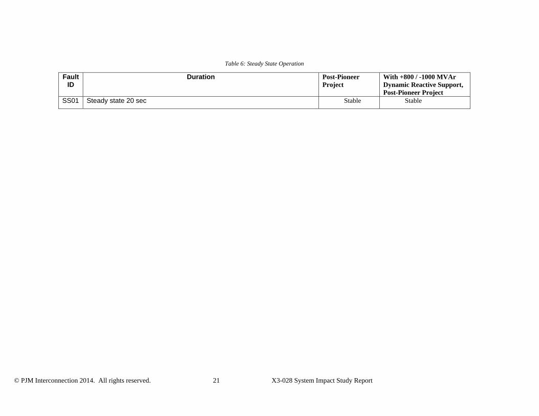
Table 6: Steady State Operation
Fault ID
Duration Post-Pioneer Project
With +800 / -1000 MVAr Dynamic Reactive Support, Post-Pioneer Project
SS01 Steady state 20 sec Stable Stable
© PJM Interconnection 2014. All rights reserved. 22 X3-028 System Impact Study Report
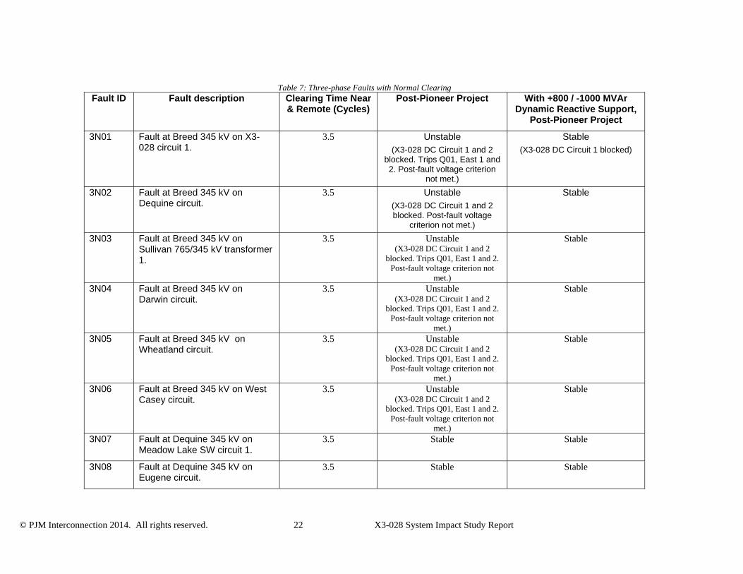
Table 7: Three-phase Faults with Normal Clearing Fault ID Fault description Clearing Time Near
& Remote (Cycles) Post-Pioneer Project With +800 / -1000 MVAr
Dynamic Reactive Support, Post-Pioneer Project
3N01 Fault at Breed 345 kV on X3-028 circuit 1.
3.5 Unstable (X3-028 DC Circuit 1 and 2
blocked. Trips Q01, East 1 and 2. Post-fault voltage criterion
not met.)
Stable (X3-028 DC Circuit 1 blocked)
3N02 Fault at Breed 345 kV on Dequine circuit.
3.5 Unstable (X3-028 DC Circuit 1 and 2 blocked. Post-fault voltage
criterion not met.)
Stable
3N03 Fault at Breed 345 kV on Sullivan 765/345 kV transformer 1.
3.5 Unstable (X3-028 DC Circuit 1 and 2
blocked. Trips Q01, East 1 and 2. Post-fault voltage criterion not
met.)
Stable
3N04 Fault at Breed 345 kV on Darwin circuit.
3.5 Unstable (X3-028 DC Circuit 1 and 2
blocked. Trips Q01, East 1 and 2. Post-fault voltage criterion not
met.)
Stable
3N05 Fault at Breed 345 kV on Wheatland circuit.
3.5 Unstable (X3-028 DC Circuit 1 and 2
blocked. Trips Q01, East 1 and 2. Post-fault voltage criterion not
met.)
Stable
3N06 Fault at Breed 345 kV on West Casey circuit.
3.5 Unstable (X3-028 DC Circuit 1 and 2
blocked. Trips Q01, East 1 and 2. Post-fault voltage criterion not
met.)
Stable
3N07 Fault at Dequine 345 kV on Meadow Lake SW circuit 1.
3.5 Stable Stable
3N08 Fault at Dequine 345 kV on Eugene circuit.
3.5 Stable Stable
© PJM Interconnection 2014. All rights reserved. 23 X3-028 System Impact Study Report
Fault ID Fault description Clearing Time Near & Remote (Cycles)
Post-Pioneer Project With +800 / -1000 MVAr Dynamic Reactive Support,
Post-Pioneer Project
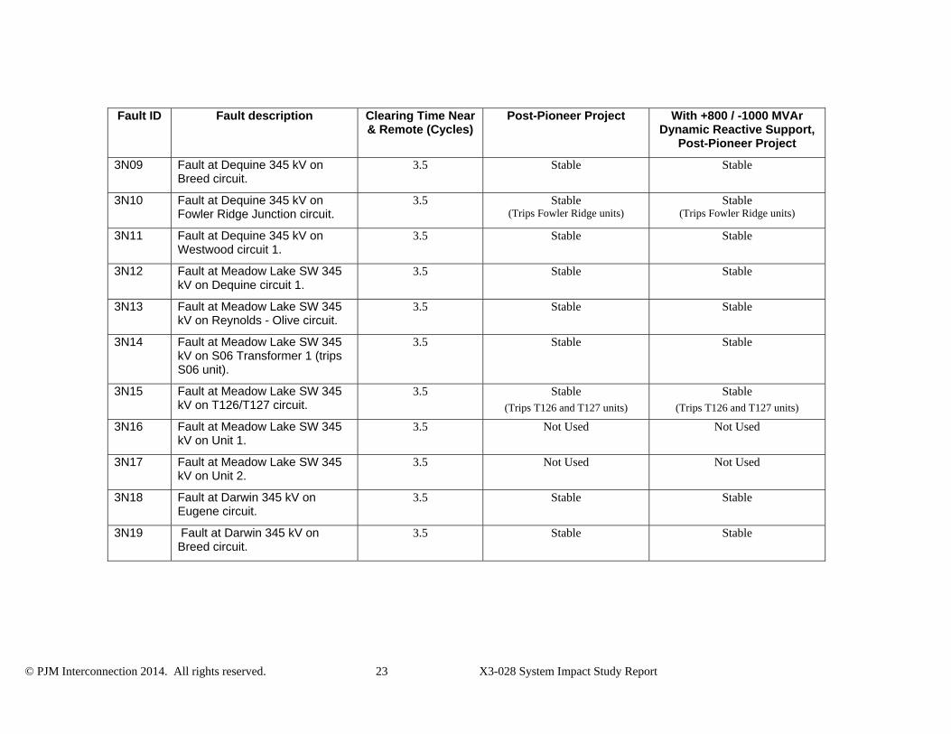
3N09 Fault at Dequine 345 kV on Breed circuit.
3.5 Stable Stable
3N10 Fault at Dequine 345 kV on Fowler Ridge Junction circuit.
3.5 Stable (Trips Fowler Ridge units)
Stable (Trips Fowler Ridge units)
3N11 Fault at Dequine 345 kV on Westwood circuit 1.
3.5 Stable Stable
3N12 Fault at Meadow Lake SW 345 kV on Dequine circuit 1.
3.5 Stable Stable
3N13 Fault at Meadow Lake SW 345 kV on Reynolds - Olive circuit.
3.5 Stable Stable
3N14 Fault at Meadow Lake SW 345 kV on S06 Transformer 1 (trips S06 unit).
3.5 Stable Stable
3N15 Fault at Meadow Lake SW 345 kV on T126/T127 circuit.
3.5 Stable (Trips T126 and T127 units)
Stable (Trips T126 and T127 units)
3N16 Fault at Meadow Lake SW 345 kV on Unit 1.
3.5 Not Used Not Used
3N17 Fault at Meadow Lake SW 345 kV on Unit 2.
3.5 Not Used Not Used
3N18 Fault at Darwin 345 kV on Eugene circuit.
3.5 Stable Stable
3N19 Fault at Darwin 345 kV on Breed circuit.
3.5 Stable Stable
© PJM Interconnection 2014. All rights reserved. 24 X3-028 System Impact Study Report
Fault ID Fault description Clearing Time Near & Remote (Cycles)
Post-Pioneer Project With +800 / -1000 MVAr Dynamic Reactive Support,
Post-Pioneer Project
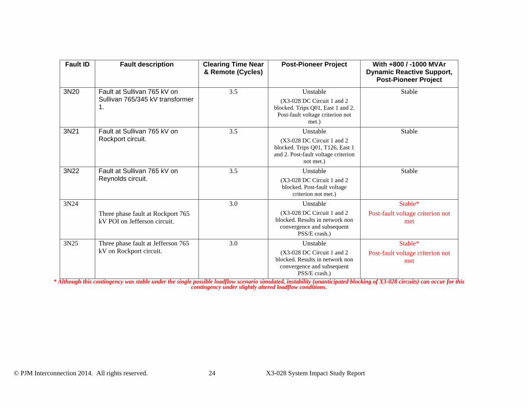
3N20 Fault at Sullivan 765 kV on Sullivan 765/345 kV transformer 1.
3.5 Unstable (X3-028 DC Circuit 1 and 2
blocked. Trips Q01, East 1 and 2. Post-fault voltage criterion not
met.)
Stable
3N21 Fault at Sullivan 765 kV on Rockport circuit.
3.5 Unstable (X3-028 DC Circuit 1 and 2
blocked. Trips Q01, T126, East 1 and 2. Post-fault voltage criterion
not met.)
Stable
3N22 Fault at Sullivan 765 kV on Reynolds circuit.
3.5 Unstable (X3-028 DC Circuit 1 and 2 blocked. Post-fault voltage
criterion not met.)
Stable
3N24
Three phase fault at Rockport 765 kV POI on Jefferson circuit.
3.0 Unstable (X3-028 DC Circuit 1 and 2
blocked. Results in network non convergence and subsequent
PSS/E crash.)
Stable*
Post-fault voltage criterion not met
3N25 Three phase fault at Jefferson 765 kV on Rockport circuit.
3.0 Unstable (X3-028 DC Circuit 1 and 2
blocked. Results in network non convergence and subsequent
PSS/E crash.)
Stable*
Post-fault voltage criterion not met
* Although this contingency was stable under the single possible loadflow scenario simulated, instability (unanticipated blocking of X3-028 circuits) can occur for this contingency under slightly altered loadflow conditions.

© PJM Interconnection 2014. All rights reserved. 25 X3-028 System Impact Study Report
Table 8: Three-phase Faults with Loss of Multiple-circuit Tower Line Fault
ID Fault description Clearing Time Near
& Remote (Cycles) Post-Pioneer Project With +800 / -1000 MVAr
Dynamic Reactive Support, Post-Pioneer
Project
3T01 Fault at Breed 345 kVon Darwin circuit resulting in tower failure. Fault cleared with loss of Dequine – Breed circuit, Darwin – Breed circuit.
3.5 Unstable (X3-028 DC Circuit 1 and 2 blocked. Post-
fault voltage criterion not met.)
Stable
3T02 Fault at Breed 345 kV on Dequine circuit resulting in tower failure. Fault cleared with loss of Dequine – Breed circuit and Dequine – Eugene circuit.
3.5 Unstable (X3-028 DC Circuit 1 and
2 blocked. Post-fault voltage criterion not met.)
Stable
3T03 Fault at Dequine 345 kV on Meadow Lake SW circuit resulting in tower failure. Fault cleared with loss of Dequine – Meadow Lake SW circuits 1 and 2.
3.5 Stable Stable
3T04 Fault at Meadow Lake 345 kV on Olive circuit resulting in tower failure. Fault cleared with loss of Meadow Lake SW – Olive circuit, Meadow Lake SW – Reynolds circuit, Olive – Reynolds circuit and Reynolds 345/138 kV Transformer 1.
3.5 Stable Stable
© PJM Interconnection 2014. All rights reserved. 26 X3-028 System Impact Study Report
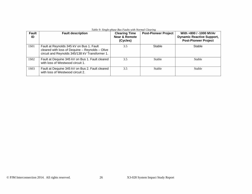
Table 9: Single-phase Bus Faults with Normal Clearing Fault
ID Fault description Clearing Time
Near & Remote (Cycles)
Post-Pioneer Project With +800 / -1000 MVAr Dynamic Reactive Support,
Post-Pioneer Project
1S01 Fault at Reynolds 345 kV on Bus 1. Fault cleared with loss of Dequine – Reynolds – Olive circuit and Reynolds 345/138 kV Transformer 1.
3.5 Stable Stable
1S02 Fault at Dequine 345 kV on Bus 1. Fault cleared with loss of Westwood circuit 1.
3.5 Stable Stable
1S03 Fault at Dequine 345 kV on Bus 2. Fault cleared with loss of Westwood circuit 2.
3.5 Stable Stable
© PJM Interconnection 2014. All rights reserved. 27 X3-028 System Impact Study Report
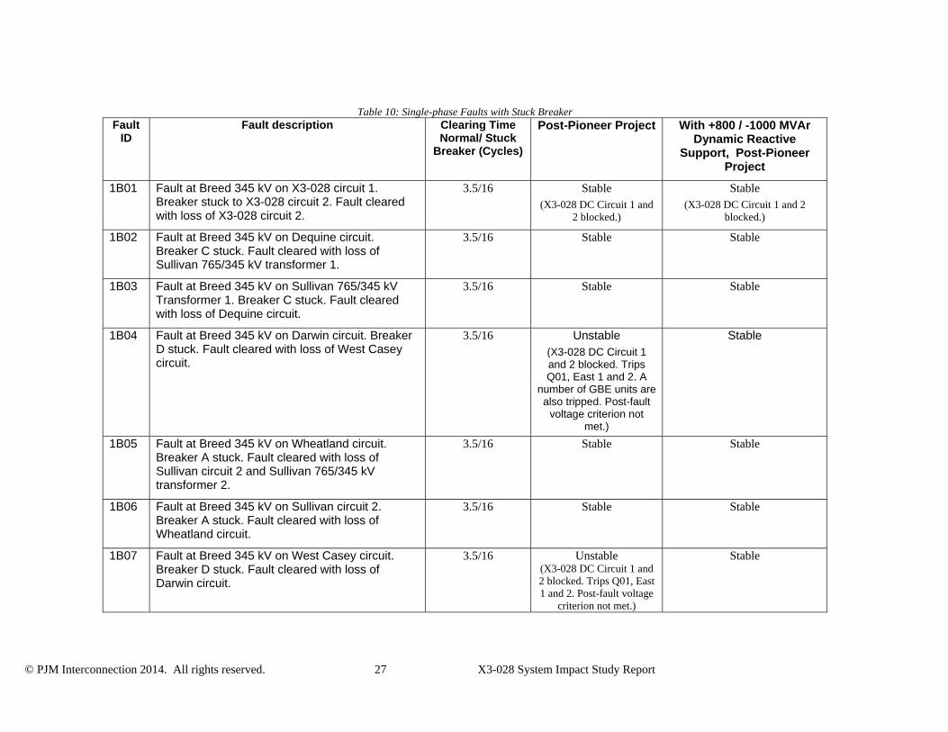
Table 10: Single-phase Faults with Stuck Breaker Fault
ID Fault description Clearing Time
Normal/ Stuck Breaker (Cycles)
Post-Pioneer Project With +800 / -1000 MVAr Dynamic Reactive
Support, Post-Pioneer Project
1B01 Fault at Breed 345 kV on X3-028 circuit 1. Breaker stuck to X3-028 circuit 2. Fault cleared with loss of X3-028 circuit 2.
3.5/16 Stable (X3-028 DC Circuit 1 and
2 blocked.)
Stable (X3-028 DC Circuit 1 and 2
blocked.)
1B02 Fault at Breed 345 kV on Dequine circuit. Breaker C stuck. Fault cleared with loss of Sullivan 765/345 kV transformer 1.
3.5/16 Stable Stable
1B03 Fault at Breed 345 kV on Sullivan 765/345 kV Transformer 1. Breaker C stuck. Fault cleared with loss of Dequine circuit.
3.5/16 Stable Stable
1B04 Fault at Breed 345 kV on Darwin circuit. Breaker D stuck. Fault cleared with loss of West Casey circuit.
3.5/16 Unstable (X3-028 DC Circuit 1 and 2 blocked. Trips Q01, East 1 and 2. A
number of GBE units are also tripped. Post-fault
voltage criterion not met.)
Stable
1B05 Fault at Breed 345 kV on Wheatland circuit. Breaker A stuck. Fault cleared with loss of Sullivan circuit 2 and Sullivan 765/345 kV transformer 2.
3.5/16 Stable Stable
1B06 Fault at Breed 345 kV on Sullivan circuit 2. Breaker A stuck. Fault cleared with loss of Wheatland circuit.
3.5/16 Stable Stable
1B07 Fault at Breed 345 kV on West Casey circuit. Breaker D stuck. Fault cleared with loss of Darwin circuit.
3.5/16 Unstable (X3-028 DC Circuit 1 and 2 blocked. Trips Q01, East 1 and 2. Post-fault voltage
criterion not met.)
Stable
© PJM Interconnection 2014. All rights reserved. 28 X3-028 System Impact Study Report
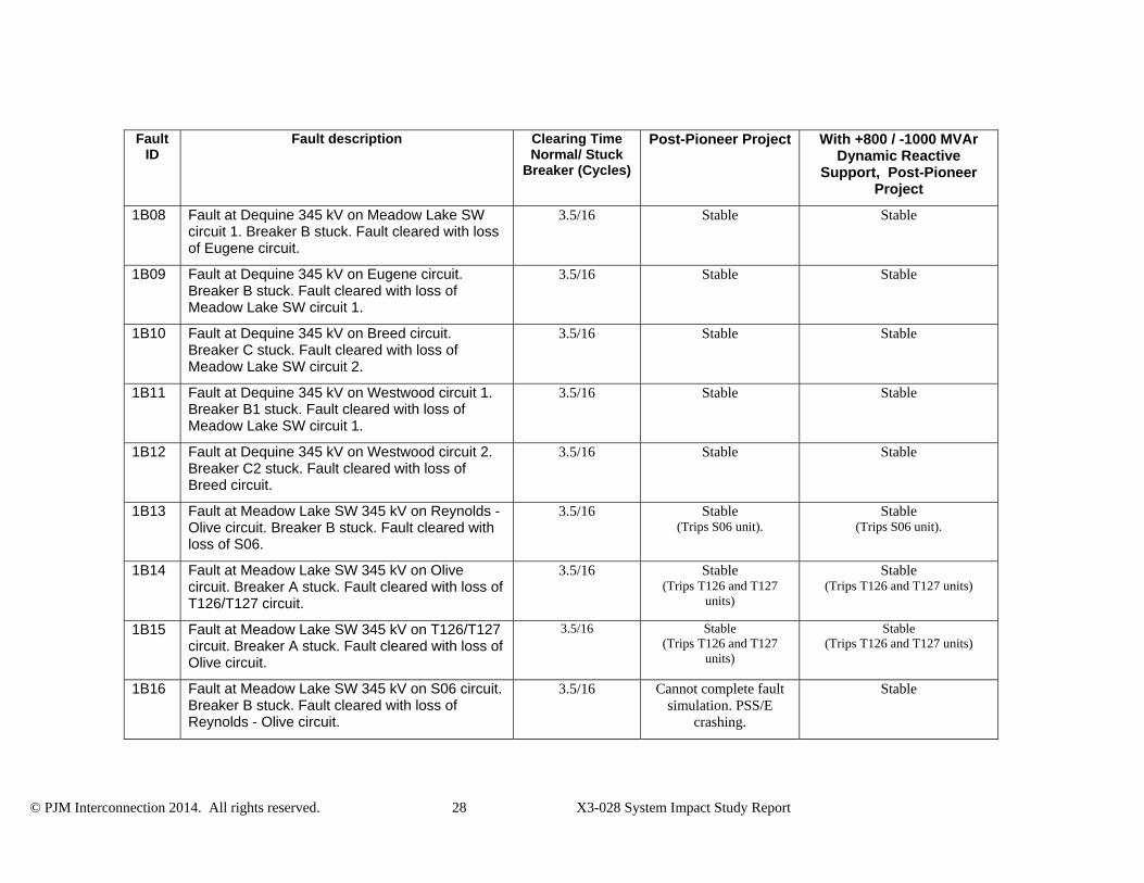
Fault ID
Fault description Clearing Time Normal/ Stuck
Breaker (Cycles)
Post-Pioneer Project With +800 / -1000 MVAr Dynamic Reactive
Support, Post-Pioneer Project
1B08 Fault at Dequine 345 kV on Meadow Lake SW circuit 1. Breaker B stuck. Fault cleared with loss of Eugene circuit.
3.5/16 Stable Stable
1B09 Fault at Dequine 345 kV on Eugene circuit. Breaker B stuck. Fault cleared with loss of Meadow Lake SW circuit 1.
3.5/16 Stable Stable
1B10 Fault at Dequine 345 kV on Breed circuit. Breaker C stuck. Fault cleared with loss of Meadow Lake SW circuit 2.
3.5/16 Stable Stable
1B11 Fault at Dequine 345 kV on Westwood circuit 1. Breaker B1 stuck. Fault cleared with loss of Meadow Lake SW circuit 1.
3.5/16 Stable Stable
1B12 Fault at Dequine 345 kV on Westwood circuit 2. Breaker C2 stuck. Fault cleared with loss of Breed circuit.
3.5/16 Stable Stable
1B13 Fault at Meadow Lake SW 345 kV on Reynolds - Olive circuit. Breaker B stuck. Fault cleared with loss of S06.
3.5/16 Stable (Trips S06 unit).
Stable (Trips S06 unit).
1B14 Fault at Meadow Lake SW 345 kV on Olive circuit. Breaker A stuck. Fault cleared with loss of T126/T127 circuit.
3.5/16 Stable (Trips T126 and T127
units)
Stable (Trips T126 and T127 units)
1B15 Fault at Meadow Lake SW 345 kV on T126/T127 circuit. Breaker A stuck. Fault cleared with loss of Olive circuit.
3.5/16 Stable (Trips T126 and T127
units)
Stable (Trips T126 and T127 units)
1B16 Fault at Meadow Lake SW 345 kV on S06 circuit. Breaker B stuck. Fault cleared with loss of Reynolds - Olive circuit.
3.5/16 Cannot complete fault simulation. PSS/E
crashing.
Stable
© PJM Interconnection 2014. All rights reserved. 29 X3-028 System Impact Study Report
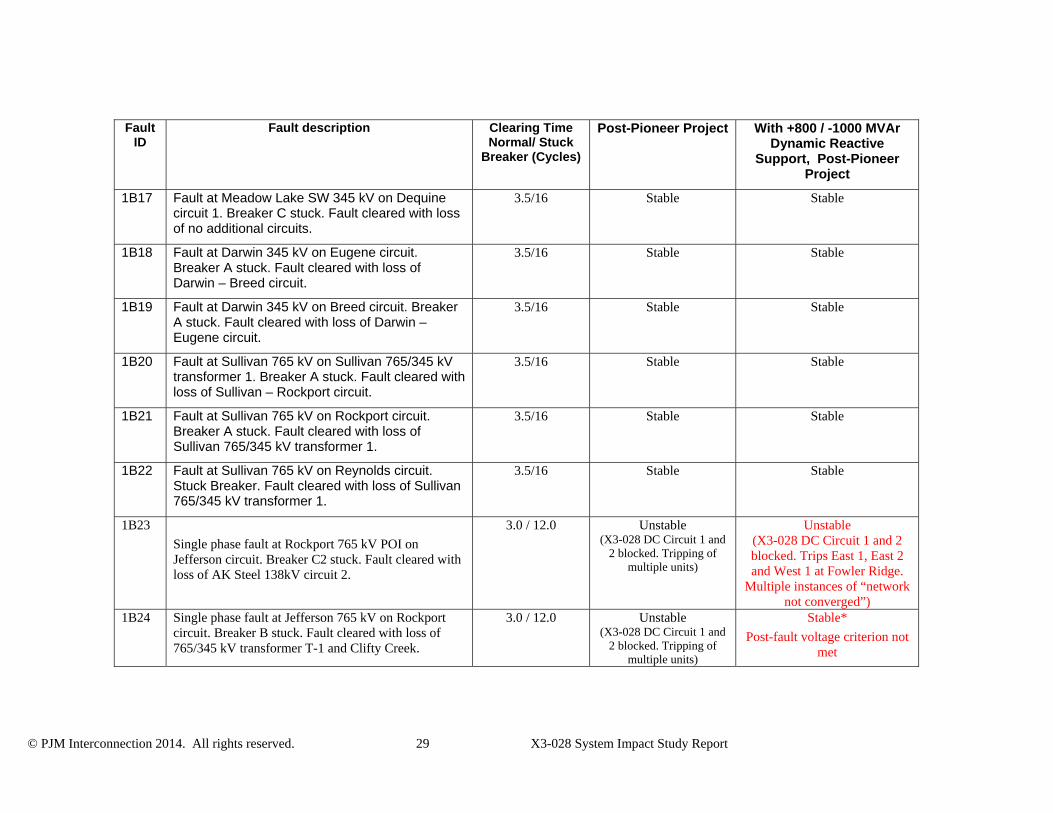
Fault ID
Fault description Clearing Time Normal/ Stuck
Breaker (Cycles)
Post-Pioneer Project With +800 / -1000 MVAr Dynamic Reactive
Support, Post-Pioneer Project
1B17 Fault at Meadow Lake SW 345 kV on Dequine circuit 1. Breaker C stuck. Fault cleared with loss of no additional circuits.
3.5/16 Stable Stable
1B18 Fault at Darwin 345 kV on Eugene circuit. Breaker A stuck. Fault cleared with loss of Darwin – Breed circuit.
3.5/16 Stable Stable
1B19 Fault at Darwin 345 kV on Breed circuit. Breaker A stuck. Fault cleared with loss of Darwin – Eugene circuit.
3.5/16 Stable Stable
1B20 Fault at Sullivan 765 kV on Sullivan 765/345 kV transformer 1. Breaker A stuck. Fault cleared with loss of Sullivan – Rockport circuit.
3.5/16 Stable Stable
1B21 Fault at Sullivan 765 kV on Rockport circuit. Breaker A stuck. Fault cleared with loss of Sullivan 765/345 kV transformer 1.
3.5/16 Stable Stable
1B22 Fault at Sullivan 765 kV on Reynolds circuit. Stuck Breaker. Fault cleared with loss of Sullivan 765/345 kV transformer 1.
3.5/16 Stable Stable
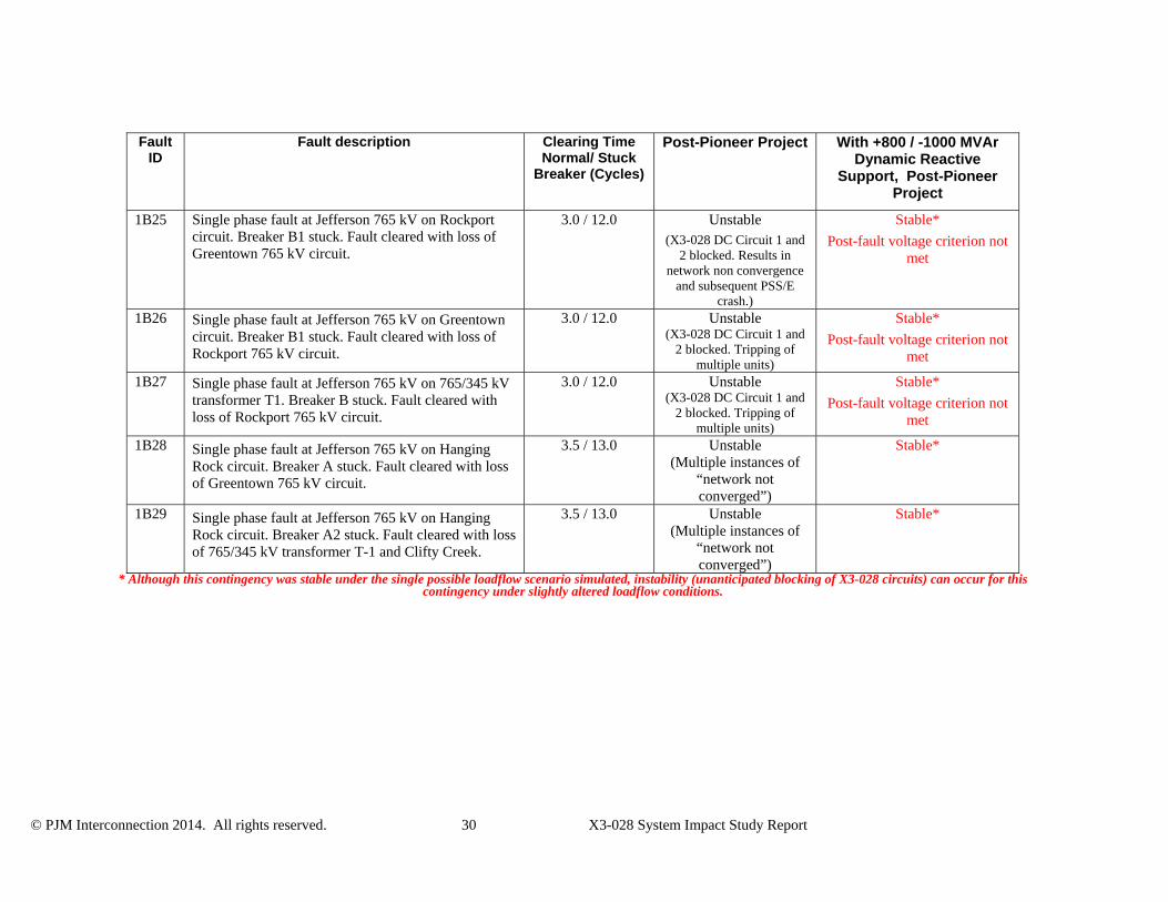
1B23
Single phase fault at Rockport 765 kV POI on Jefferson circuit. Breaker C2 stuck. Fault cleared with loss of AK Steel 138kV circuit 2.
3.0 / 12.0 Unstable (X3-028 DC Circuit 1 and
2 blocked. Tripping of multiple units)
Unstable (X3-028 DC Circuit 1 and 2 blocked. Trips East 1, East 2 and West 1 at Fowler Ridge.
Multiple instances of “network not converged”)
1B24 Single phase fault at Jefferson 765 kV on Rockport circuit. Breaker B stuck. Fault cleared with loss of 765/345 kV transformer T-1 and Clifty Creek.
3.0 / 12.0 Unstable (X3-028 DC Circuit 1 and
2 blocked. Tripping of multiple units)
Stable*
Post-fault voltage criterion not met
© PJM Interconnection 2014. All rights reserved. 30 X3-028 System Impact Study Report
Fault ID
Fault description Clearing Time Normal/ Stuck
Breaker (Cycles)
Post-Pioneer Project With +800 / -1000 MVAr Dynamic Reactive
Support, Post-Pioneer Project
1B25 Single phase fault at Jefferson 765 kV on Rockport circuit. Breaker B1 stuck. Fault cleared with loss of Greentown 765 kV circuit.
3.0 / 12.0 Unstable (X3-028 DC Circuit 1 and
2 blocked. Results in network non convergence
and subsequent PSS/E crash.)
Stable*
Post-fault voltage criterion not met
1B26 Single phase fault at Jefferson 765 kV on Greentown circuit. Breaker B1 stuck. Fault cleared with loss of Rockport 765 kV circuit.
3.0 / 12.0 Unstable (X3-028 DC Circuit 1 and
2 blocked. Tripping of multiple units)
Stable*
Post-fault voltage criterion not met
1B27 Single phase fault at Jefferson 765 kV on 765/345 kV transformer T1. Breaker B stuck. Fault cleared with loss of Rockport 765 kV circuit.
3.0 / 12.0 Unstable (X3-028 DC Circuit 1 and
2 blocked. Tripping of multiple units)
Stable*
Post-fault voltage criterion not met
1B28 Single phase fault at Jefferson 765 kV on Hanging Rock circuit. Breaker A stuck. Fault cleared with loss of Greentown 765 kV circuit.
3.5 / 13.0 Unstable (Multiple instances of
“network not converged”)
Stable*
1B29 Single phase fault at Jefferson 765 kV on Hanging Rock circuit. Breaker A2 stuck. Fault cleared with loss of 765/345 kV transformer T-1 and Clifty Creek.
3.5 / 13.0 Unstable (Multiple instances of
“network not converged”)
Stable*
* Although this contingency was stable under the single possible loadflow scenario simulated, instability (unanticipated blocking of X3-028 circuits) can occur for this contingency under slightly altered loadflow conditions.
© PJM Interconnection 2014. All rights reserved. 31 X3-028 System Impact Study Report
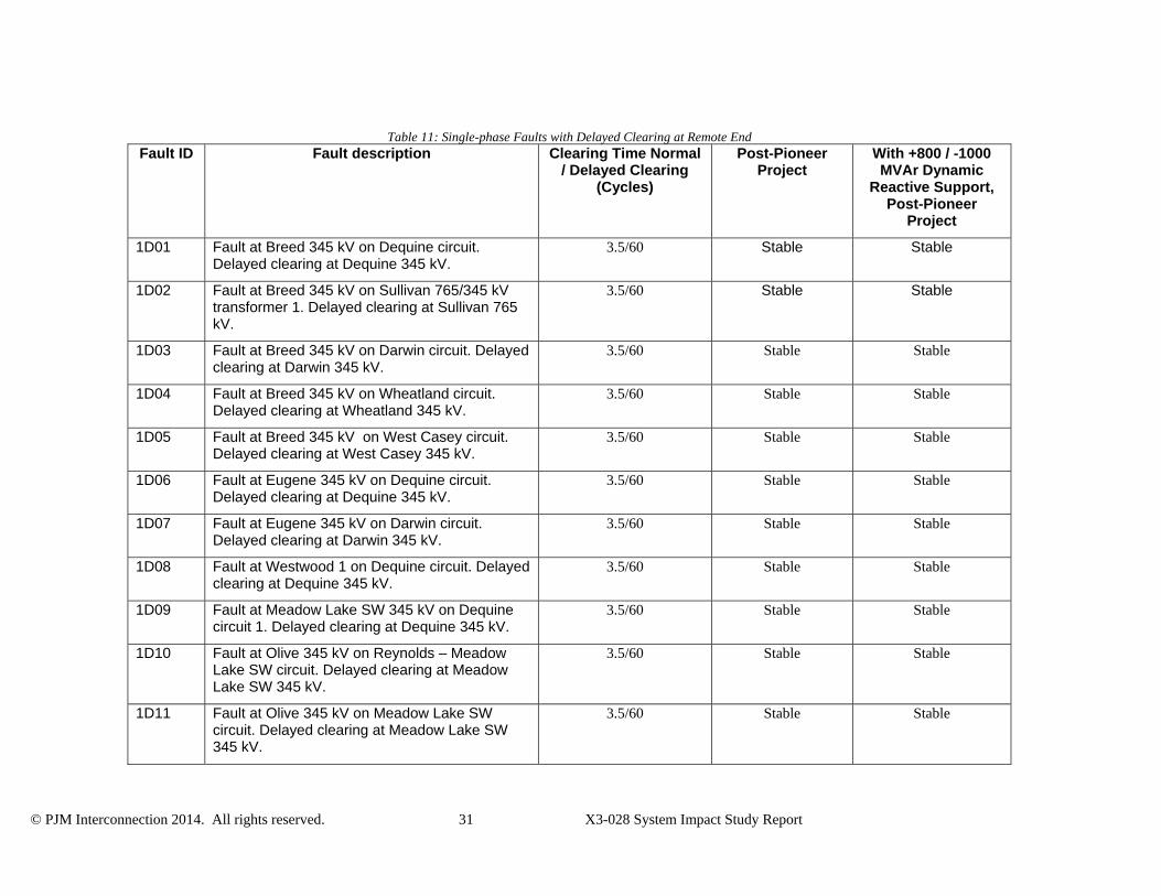
Table 11: Single-phase Faults with Delayed Clearing at Remote End Fault ID Fault description Clearing Time Normal
/ Delayed Clearing (Cycles)
Post-Pioneer Project
With +800 / -1000 MVAr Dynamic
Reactive Support, Post-Pioneer
Project
1D01 Fault at Breed 345 kV on Dequine circuit. Delayed clearing at Dequine 345 kV.
3.5/60 Stable Stable
1D02 Fault at Breed 345 kV on Sullivan 765/345 kV transformer 1. Delayed clearing at Sullivan 765 kV.
3.5/60 Stable Stable
1D03 Fault at Breed 345 kV on Darwin circuit. Delayed clearing at Darwin 345 kV.
3.5/60 Stable Stable
1D04 Fault at Breed 345 kV on Wheatland circuit. Delayed clearing at Wheatland 345 kV.
3.5/60 Stable Stable
1D05 Fault at Breed 345 kV on West Casey circuit. Delayed clearing at West Casey 345 kV.
3.5/60 Stable Stable
1D06 Fault at Eugene 345 kV on Dequine circuit. Delayed clearing at Dequine 345 kV.
3.5/60 Stable Stable
1D07 Fault at Eugene 345 kV on Darwin circuit. Delayed clearing at Darwin 345 kV.
3.5/60 Stable Stable
1D08 Fault at Westwood 1 on Dequine circuit. Delayed clearing at Dequine 345 kV.
3.5/60 Stable Stable
1D09 Fault at Meadow Lake SW 345 kV on Dequine circuit 1. Delayed clearing at Dequine 345 kV.
3.5/60 Stable Stable
1D10 Fault at Olive 345 kV on Reynolds – Meadow Lake SW circuit. Delayed clearing at Meadow Lake SW 345 kV.
3.5/60 Stable Stable
1D11 Fault at Olive 345 kV on Meadow Lake SW circuit. Delayed clearing at Meadow Lake SW 345 kV.
3.5/60 Stable Stable
© PJM Interconnection 2014. All rights reserved. 32 X3-028 System Impact Study Report
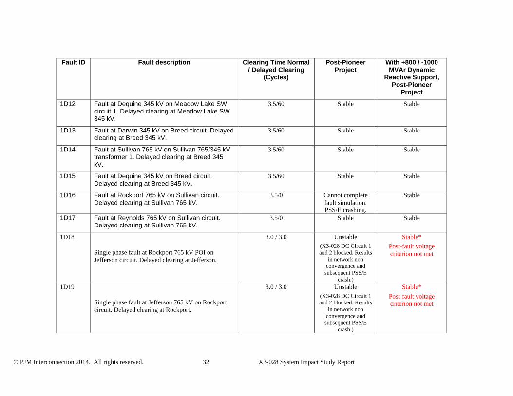
Fault ID Fault description Clearing Time Normal / Delayed Clearing
(Cycles)
Post-Pioneer Project
With +800 / -1000 MVAr Dynamic
Reactive Support, Post-Pioneer
Project
1D12 Fault at Dequine 345 kV on Meadow Lake SW circuit 1. Delayed clearing at Meadow Lake SW 345 kV.
3.5/60 Stable Stable
1D13 Fault at Darwin 345 kV on Breed circuit. Delayed clearing at Breed 345 kV.
3.5/60 Stable Stable
1D14 Fault at Sullivan 765 kV on Sullivan 765/345 kV transformer 1. Delayed clearing at Breed 345 kV.
3.5/60 Stable Stable
1D15 Fault at Dequine 345 kV on Breed circuit. Delayed clearing at Breed 345 kV.
3.5/60 Stable Stable
1D16 Fault at Rockport 765 kV on Sullivan circuit. Delayed clearing at Sullivan 765 kV.
3.5/0 Cannot complete fault simulation. PSS/E crashing.
Stable
1D17 Fault at Reynolds 765 kV on Sullivan circuit. Delayed clearing at Sullivan 765 kV.
3.5/0 Stable Stable
1D18
Single phase fault at Rockport 765 kV POI on Jefferson circuit. Delayed clearing at Jefferson.
3.0 / 3.0 Unstable (X3-028 DC Circuit 1 and 2 blocked. Results
in network non convergence and
subsequent PSS/E crash.)
Stable*
Post-fault voltage criterion not met
1D19
Single phase fault at Jefferson 765 kV on Rockport circuit. Delayed clearing at Rockport.
3.0 / 3.0 Unstable (X3-028 DC Circuit 1 and 2 blocked. Results
in network non convergence and
subsequent PSS/E crash.)
Stable*
Post-fault voltage criterion not met
© PJM Interconnection 2014. All rights reserved. 33 X3-028 System Impact Study Report
* Although this contingency was stable under the single possible loadflow scenario simulated, instability (unanticipated blocking of X3-028 circuits) can occur for this contingency under slightly altered loadflow conditions.
© PJM Interconnection 2014. All rights reserved. 34 X3-028 System Impact Study Report
Table 12: Three-phase Faults under Outages Without Dynamic Reactive Support Equipment
Under Outage
Fault ID Fault description Clearing Time
(Cycles)
Post-Pioneer Project With +800 / -1000 MVAr Dynamic
Reactive Support6, Post-Pioneer Project
Breed – West Casey 345 kV circuit
MA.3N01 Fault at Breed 345 kV on X3-028 circuit 1.
3.5 Unstable (X3-028 DC Circuit 1 and 2 blocked. Nearby wind
machines tripped)
Stable (X3-028 DC Circuit 1 and
2 blocked)
MA.3N02 Fault at Breed 345 kV (on Dequine circuit.
3.5 Unstable (X3-028 DC Circuit 1 and 2 blocked. Multiple instances
of “network failed to converge” results in PSS/E
crash)
Stable
MA.3N03 Fault at Breed 345 kV on Sullivan 765/345 kV transformer 1.
3.5 Unstable (X3-028 DC Circuit 1 and 2 blocked. Multiple instances
of “network failed to converge” results in PSS/E
crash)
Stable
MA.3N04 Fault at Breed 345 kV (X3-028 POI) on Darwin circuit.
3.5 Unstable (X3-028 DC Circuit 1 and 2
blocked. Nearby wind machines tripped)
Stable
MA.3N05 Fault at Breed 345 kV (X3-028 POI) on Wheatland circuit.
3.5 Unstable (X3-028 DC Circuit 1 and 2 blocked. Multiple instances
of “network failed to converge” results in PSS/E
crash)
Stable
MA.3N07 Fault at Dequine 345 kV on Meadow Lake SW circuit 1.
3.5 Stable Stable
6 In addition to the +800 / -1000 MVAr dynamic reactive support, for an outage on the Breed – West Casey 345 kV circuit X3-028 HVDC circuit injection was curtailed to 1500 MW (the Firm Transmission Injection Right value) in the load flow to maintain dynamic stability.
© PJM Interconnection 2014. All rights reserved. 35 X3-028 System Impact Study Report
Equipment Under Outage
Fault ID Fault description Clearing Time
(Cycles)
Post-Pioneer Project With +800 / -1000 MVAr Dynamic
Reactive Support6, Post-Pioneer Project
MA.3N09 Fault at Dequine 345 kV on Breed circuit.
3.5 Stable Stable
MA.3N10 Fault at Dequine 345 kV on Fowler Ridge Junction circuit.
3.5 Stable (Trips Fowler Ridge units)
Stable (Trips Fowler Ridge units)
MA.3N15 Fault at Meadow Lake SW 345 kV on T126/T127 circuit.
3.5 Stable (Trips T126 and T127 units)
Stable (Trips T126 and T127 units)
MA.3N18 Fault at Darwin 345 kV on Eugene circuit.
3.5 Stable Stable
MA.3N19 Fault at Darwin 345 kV on Breed circuit.
3.5 Stable Stable
MA.3N20 Fault at Sullivan 765 kV on Sullivan 765/345 kV transformer 1.
3.5 Unstable (X3-028 DC Circuit 1 and 2 blocked. Multiple instances
of “network failed to converge” results in PSS/E
crash)
Stable
MA.3N21 Fault at Sullivan 765 kV on Rockport circuit.
3.5 Unstable (X3-028 DC Circuit 1 and 2
blocked. Nearby wind machines tripped)
Stable
MA.3N23 Fault at Rockport 765 kV on Sullivan circuit.
3.5 Stable Stable
MA.3N24 Fault at Rockport 765 kV on Jefferson circuit. (Fast Valving on Rockport units active)
3.5 Unstable (X3-028 DC Circuit 1 and 2 blocked. Multiple instances
of “network failed to converge” results in PSS/E
crash)
Stable
© PJM Interconnection 2014. All rights reserved. 36 X3-028 System Impact Study Report
Equipment Under Outage
Fault ID Fault description Clearing Time
(Cycles)
Post-Pioneer Project With +800 / -1000 MVAr Dynamic
Reactive Support6, Post-Pioneer Project
MA.3N25 Fault at Jefferson 765 kV on Greentown circuit.
3.5 Stable Stable
MA.3N26 Fault at Jefferson 765 kV on Hanging Rock circuit.
3.5 Stable Stable
Rockport – Jefferson 765 kV circuit
MB.3N01 Fault at Breed 345 kV (X3-028 POI) on X3-028 circuit 1.
3.5 Unstable (X3-028 DC Circuit 1 and
2 blocked. Multiple instances of “network
failed to converge” results in PSS/E crash)
Stable
MB.3N02 Fault at Breed 345 kV (X3-028 POI) on Dequine circuit.
3.5 Unstable (X3-028 DC Circuit 1 and 2
blocked. Nearby wind machines tripped)
Stable
MB.3N03 Fault at Breed 345 kV (X3-028 POI) on Sullivan 765/345 kV transformer 1.
3.5 Unstable (X3-028 DC Circuit 1 and 2
blocked. Nearby wind machines tripped)
Stable
MB.3N04 Fault at Breed 345 kV (X3-028 POI) on Darwin circuit.
3.5 Unstable (X3-028 DC Circuit 1 and 2 blocked. Multiple instances
of “network failed to converge” results in PSS/E
crash)
Stable
MB.3N05 Fault at Breed 345 kV (X3-028 POI) on Wheatland circuit.
3.5 Unstable (X3-028 DC Circuit 1 and 2
blocked. Nearby wind machines tripped)
Stable
MB.3N06 Fault at Breed 345 kV (X3-028 POI) on West Casey circuit.
3.5 Unstable (X3-028 DC Circuit 1 and 2
blocked. Nearby wind machines tripped)
Stable

© PJM Interconnection 2014. All rights reserved. 37 X3-028 System Impact Study Report
Equipment Under Outage
Fault ID Fault description Clearing Time
(Cycles)
Post-Pioneer Project With +800 / -1000 MVAr Dynamic
Reactive Support6, Post-Pioneer Project
MB.3N07 Fault at Dequine 345 kV on Meadow Lake SW circuit 1.
3.5 Stable
Stable
MB.3N09 Fault at Dequine 345 kV on Breed circuit.
3.5 Stable Stable
MB.3N10 Fault at Dequine 345 kV on Fowler Ridge Junction circuit.
3.5 Network failed to converge, results in
PSS/E crash.
Stable (Trips Fowler Ridge units)
MB.3N15 Fault at Meadow Lake SW 345 kV on T126/T127 circuit.
3.5 Stable (Trips T126 and T127 units)
Stable (Trips T126 and T127 units)
MB.3N18 Fault at Darwin 345 kV on Eugene circuit.
3.5 Stable Stable
MB.3N19 Fault at Darwin 345 kV on Breed circuit.
3.5 Stable Stable
MB.3N20 Fault at Sullivan 765 kV on Sullivan 765/345 kV transformer 1.
3.5 Unstable (X3-028 DC Circuit 1 and 2 blocked. Multiple instances
of “network failed to converge” results in PSS/E
crash)
Stable
MB.3N21 Fault at Sullivan 765 kV on Rockport circuit.
3.5 Unstable (X3-028 DC Circuit 1 and 2 blocked. Multiple instances
of “network failed to converge” results in PSS/E
crash)
Stable
MB.3N23 Fault at Rockport 765 kV on Sullivan circuit.
3.5 Stable Stable
© PJM Interconnection 2014. All rights reserved. 38 X3-028 System Impact Study Report
Equipment Under Outage
Fault ID Fault description Clearing Time
(Cycles)
Post-Pioneer Project With +800 / -1000 MVAr Dynamic
Reactive Support6, Post-Pioneer Project
MB.3N25 Fault at Jefferson 765 kV on Greentown circuit.
3.5 Stable Stable
MB.3N26 Fault at Jefferson 765 kV on Hanging Rock circuit.
3.5 Stable Stable

© PJM Interconnection 2014. All rights reserved. 39 X3-028 System Impact Study Report
Attachment1.X3‐028ImpactStudyData
Attachment1a.X3‐028ImpactStudyDataForm
Attachment1b.ThePioneerProjectone‐linediagram
Attachment2.AEPOneLineDiagram
Attachment3.PSS/EModelOneLineDiagram
Attachment4.X3‐028PSS/ECaseData
Attachment5.X3‐028PSS/EDynamicsData
Attachment6.PlotsfromDynamicSimulations
Attachment6a.PlotsfromDynamicSimulations–IntactNetworkResults from fault contingencies applied on intact network, both without and with +800/-1000 MVAr dynamic reactive support at X3-028.
Attachment6b.PlotsfromDynamicSimulations–OutagesResults from fault contingencies applied on network with outages, both without and with +800/-1000 MVAr dynamic reactive support at X3-028. In addition to the +800/-1000 MVAr dynamic reactive support, for an outage on the Breed – West Casey 345 kV circuit, the X3-028 injection was curtailed to 1500 MW in the load flow.
Attachment7.FaultAdmittances
© PJM Interconnection 2014. All rights reserved. 40 X3-028 System Impact Study Report
Appendices The following appendices contain additional information about each flowgate presented in the body of the report. For each appendix, a description of the flowgate and its contingency was included for convenience. However, the intent of the appendix section is to provide more information on which projects/generators have contributions to the flowgate in question. Although this information is not used "as is" for cost allocation purposes, it can be used to gage other generators impact. It should be noted the generator contributions presented in the appendices sections are full contributions, whereas in the body of the report, those contributions take into consideration the commercial probability of each project.
© PJM Interconnection 2014. All rights reserved. 41 X3-028 System Impact Study Report
Appendix 1
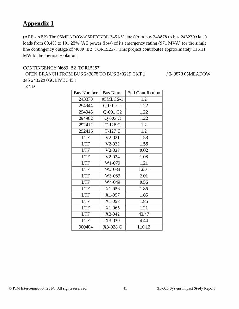
(AEP - AEP) The 05MEADOW-05REYNOL 345 kV line (from bus 243878 to bus 243230 ckt 1) loads from 89.4% to 101.28% (AC power flow) of its emergency rating (971 MVA) for the single line contingency outage of '4689_B2_TOR15257'. This project contributes approximately 116.11 MW to the thermal violation. CONTINGENCY '4689_B2_TOR15257' OPEN BRANCH FROM BUS 243878 TO BUS 243229 CKT 1 / 243878 05MEADOW 345 243229 05OLIVE 345 1 END
Bus Number Bus Name Full Contribution243879 05MLCS-1 1.2 294944 Q-001 C1 1.22 294945 Q-001 C2 1.22 294962 Q-003 C 1.22 292412 T-126 C 1.2 292416 T-127 C 1.2
LTF V2-031 1.58 LTF V2-032 1.56 LTF V2-033 0.02 LTF V2-034 1.08 LTF W1-079 1.21 LTF W2-033 12.01 LTF W3-083 2.01 LTF W4-049 0.56 LTF X1-056 1.85 LTF X1-057 1.85 LTF X1-058 1.85 LTF X1-065 1.21 LTF X2-042 43.47 LTF X3-020 4.44
900404 X3-028 C 116.12
© PJM Interconnection 2014. All rights reserved. 42 X3-028 System Impact Study Report
Appendix 2
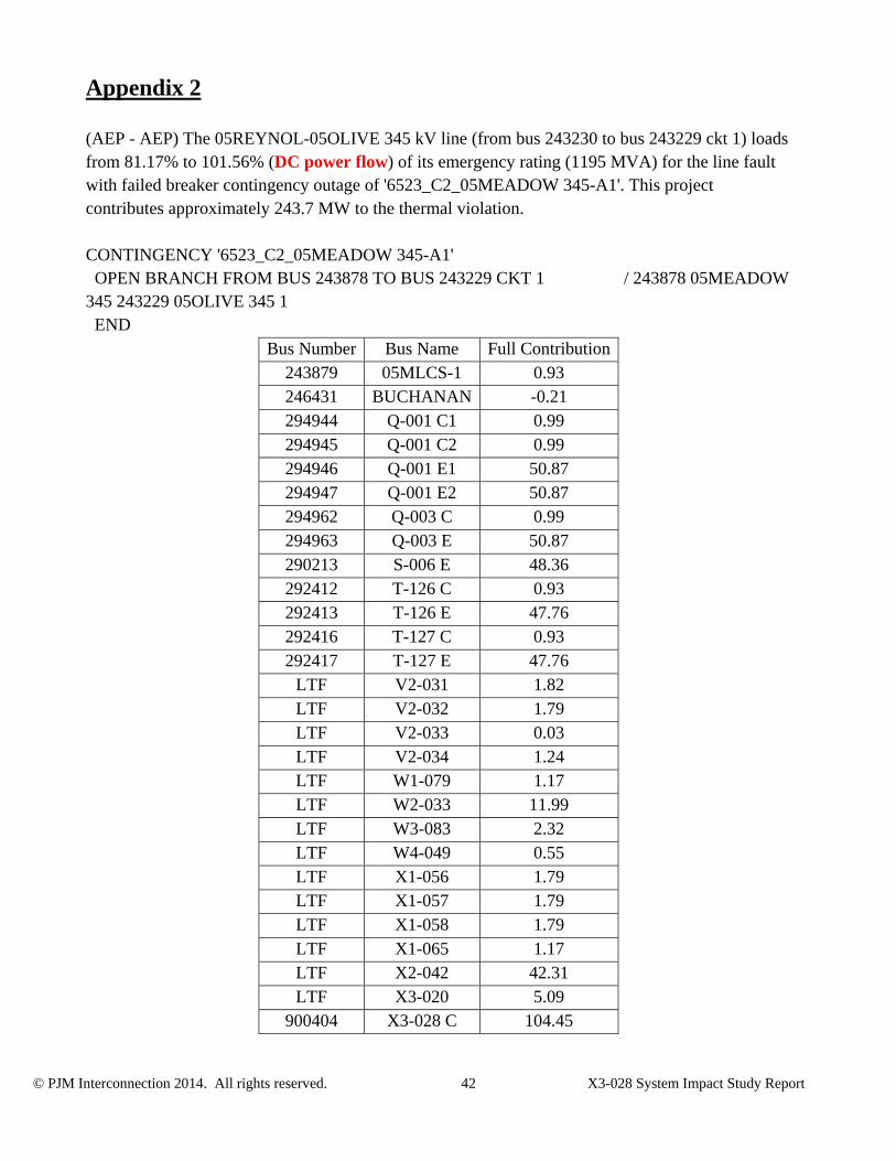
(AEP - AEP) The 05REYNOL-05OLIVE 345 kV line (from bus 243230 to bus 243229 ckt 1) loads from 81.17% to 101.56% (DC power flow) of its emergency rating (1195 MVA) for the line fault with failed breaker contingency outage of '6523_C2_05MEADOW 345-A1'. This project contributes approximately 243.7 MW to the thermal violation. CONTINGENCY '6523_C2_05MEADOW 345-A1' OPEN BRANCH FROM BUS 243878 TO BUS 243229 CKT 1 / 243878 05MEADOW 345 243229 05OLIVE 345 1 END
Bus Number Bus Name Full Contribution243879 05MLCS-1 0.93 246431 BUCHANAN -0.21 294944 Q-001 C1 0.99 294945 Q-001 C2 0.99 294946 Q-001 E1 50.87 294947 Q-001 E2 50.87 294962 Q-003 C 0.99 294963 Q-003 E 50.87 290213 S-006 E 48.36 292412 T-126 C 0.93 292413 T-126 E 47.76 292416 T-127 C 0.93 292417 T-127 E 47.76
LTF V2-031 1.82 LTF V2-032 1.79 LTF V2-033 0.03 LTF V2-034 1.24 LTF W1-079 1.17 LTF W2-033 11.99 LTF W3-083 2.32 LTF W4-049 0.55 LTF X1-056 1.79 LTF X1-057 1.79 LTF X1-058 1.79 LTF X1-065 1.17 LTF X2-042 42.31 LTF X3-020 5.09
900404 X3-028 C 104.45
© PJM Interconnection 2014. All rights reserved. 43 X3-028 System Impact Study Report
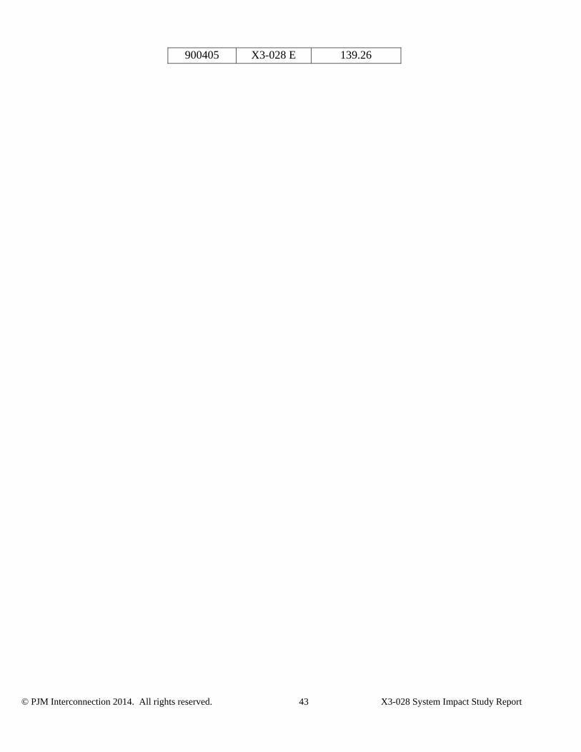
900405 X3-028 E 139.26
© PJM Interconnection 2014. All rights reserved. 44 X3-028 System Impact Study Report
Appendix 3
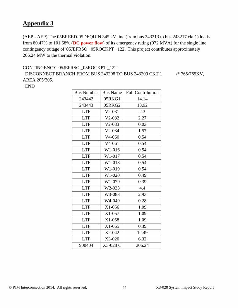
(AEP - AEP) The 05BREED-05DEQUIN 345 kV line (from bus 243213 to bus 243217 ckt 1) loads from 80.47% to 101.68% (DC power flow) of its emergency rating (972 MVA) for the single line contingency outage of '05JEFRSO _05ROCKPT _122'. This project contributes approximately 206.24 MW to the thermal violation. CONTINGENCY '05JEFRSO _05ROCKPT _122' DISCONNECT BRANCH FROM BUS 243208 TO BUS 243209 CKT 1 /* 765/765KV, AREA 205/205. END
Bus Number Bus Name Full Contribution243442 05RKG1 14.14 243443 05RKG2 13.92
LTF V2-031 2.3 LTF V2-032 2.27 LTF V2-033 0.03 LTF V2-034 1.57 LTF V4-060 0.54 LTF V4-061 0.54 LTF W1-016 0.54 LTF W1-017 0.54 LTF W1-018 0.54 LTF W1-019 0.54 LTF W1-020 0.49 LTF W1-079 0.39 LTF W2-033 4.4 LTF W3-083 2.93 LTF W4-049 0.28 LTF X1-056 1.09 LTF X1-057 1.09 LTF X1-058 1.09 LTF X1-065 0.39 LTF X2-042 12.49 LTF X3-020 6.32
900404 X3-028 C 206.24
© PJM Interconnection 2014. All rights reserved. 45 X3-028 System Impact Study Report
Appendix 4
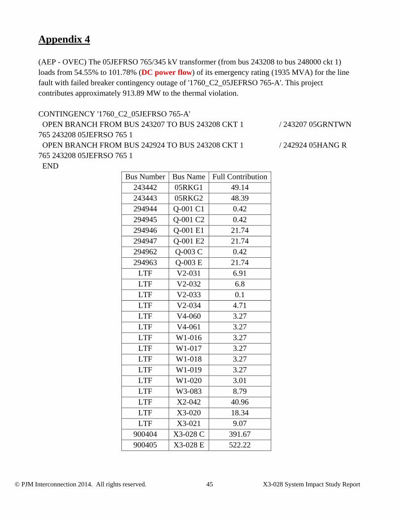
(AEP - OVEC) The 05JEFRSO 765/345 kV transformer (from bus 243208 to bus 248000 ckt 1) loads from 54.55% to 101.78% (DC power flow) of its emergency rating (1935 MVA) for the line fault with failed breaker contingency outage of '1760_C2_05JEFRSO 765-A'. This project contributes approximately 913.89 MW to the thermal violation. CONTINGENCY '1760_C2_05JEFRSO 765-A' OPEN BRANCH FROM BUS 243207 TO BUS 243208 CKT 1 / 243207 05GRNTWN 765 243208 05JEFRSO 765 1 OPEN BRANCH FROM BUS 242924 TO BUS 243208 CKT 1 / 242924 05HANG R 765 243208 05JEFRSO 765 1 END
Bus Number Bus Name Full Contribution243442 05RKG1 49.14 243443 05RKG2 48.39 294944 Q-001 C1 0.42 294945 Q-001 C2 0.42 294946 Q-001 E1 21.74 294947 Q-001 E2 21.74 294962 Q-003 C 0.42 294963 Q-003 E 21.74
LTF V2-031 6.91 LTF V2-032 6.8 LTF V2-033 0.1 LTF V2-034 4.71 LTF V4-060 3.27 LTF V4-061 3.27 LTF W1-016 3.27 LTF W1-017 3.27 LTF W1-018 3.27 LTF W1-019 3.27 LTF W1-020 3.01 LTF W3-083 8.79 LTF X2-042 40.96 LTF X3-020 18.34 LTF X3-021 9.07
900404 X3-028 C 391.67 900405 X3-028 E 522.22

© PJM Interconnection 2014. All rights reserved. 46 X3-028 System Impact Study Report
Appendix 5
(AEP - AEP) The 05DARWIN-05EUGENE 345 kV line (from bus 243216 to bus 243221 ckt 1) loads from 52.14% to 105.69% (DC power flow) of its emergency rating (1419 MVA) for the line fault with failed breaker contingency outage of '3002_C2'. This project contributes approximately 759.96 MW to the thermal violation. CONTINGENCY '3002_C2' OPEN BRANCH FROM BUS 243208 TO BUS 243209 CKT 1 / 243208 05JEFRSO 765 243209 05ROCKPT 765 1 OPEN BRANCH FROM BUS 243209 TO BUS 243240 CKT 8 / 243209 05ROCKPT 765 243240 05AKSTL2 138 8 END
Bus Number Bus Name Full Contribution243442 05RKG1 22.33 243443 05RKG2 21.99
LTF V2-031 2.54 LTF V2-032 2.51 LTF V2-033 0.04 LTF V2-034 1.74 LTF V4-060 0.81 LTF V4-061 0.81 LTF W1-016 0.81 LTF W1-017 0.81 LTF W1-018 0.81 LTF W1-019 0.81 LTF W1-020 0.75 LTF W2-033 0.97 LTF W3-083 3.24 LTF W4-049 0.11 LTF X1-056 0.42 LTF X1-057 0.42 LTF X1-058 0.42 LTF X3-020 6.9
900404 X3-028 C 325.7 900405 X3-028 E 434.26

© PJM Interconnection 2014. All rights reserved. 47 X3-028 System Impact Study Report
Appendix 6
(AEP - AEP) The 05DARWIN-05EUGENE 345 kV line (from bus 243216 to bus 243221 ckt 1) loads from 52.14% to 105.69% (DC power flow) of its emergency rating (1419 MVA) for the line fault with failed breaker contingency outage of '3183_C2'. This project contributes approximately 759.96 MW to the thermal violation. CONTINGENCY '3183_C2' OPEN BRANCH FROM BUS 243208 TO BUS 243209 CKT 1 / 243208 05JEFRSO 765 243209 05ROCKPT 765 1 OPEN BRANCH FROM BUS 243209 TO BUS 243239 CKT 7 / 243209 05ROCKPT 765 243239 05AKSTL1 138 7 END
Bus Number Bus Name Full Contribution243442 05RKG1 22.33 243443 05RKG2 21.99
LTF V2-031 2.54 LTF V2-032 2.51 LTF V2-033 0.04 LTF V2-034 1.74 LTF V4-060 0.81 LTF V4-061 0.81 LTF W1-016 0.81 LTF W1-017 0.81 LTF W1-018 0.81 LTF W1-019 0.81 LTF W1-020 0.75 LTF W2-033 0.97 LTF W3-083 3.24 LTF W4-049 0.11 LTF X1-056 0.42 LTF X1-057 0.42 LTF X1-058 0.42 LTF X3-020 6.9
900404 X3-028 C 325.7 900405 X3-028 E 434.26
© PJM Interconnection 2014. All rights reserved. 48 X3-028 System Impact Study Report
Appendix 7
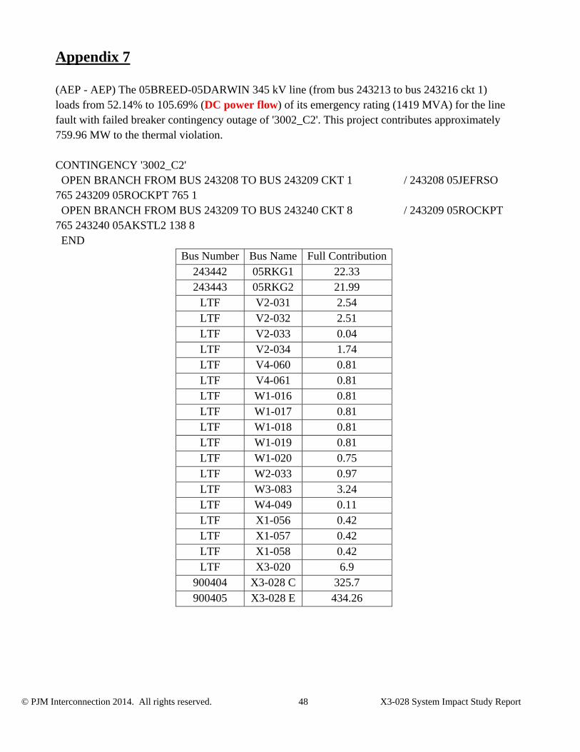
(AEP - AEP) The 05BREED-05DARWIN 345 kV line (from bus 243213 to bus 243216 ckt 1) loads from 52.14% to 105.69% (DC power flow) of its emergency rating (1419 MVA) for the line fault with failed breaker contingency outage of '3002_C2'. This project contributes approximately 759.96 MW to the thermal violation. CONTINGENCY '3002_C2' OPEN BRANCH FROM BUS 243208 TO BUS 243209 CKT 1 / 243208 05JEFRSO 765 243209 05ROCKPT 765 1 OPEN BRANCH FROM BUS 243209 TO BUS 243240 CKT 8 / 243209 05ROCKPT 765 243240 05AKSTL2 138 8 END
Bus Number Bus Name Full Contribution243442 05RKG1 22.33 243443 05RKG2 21.99
LTF V2-031 2.54 LTF V2-032 2.51 LTF V2-033 0.04 LTF V2-034 1.74 LTF V4-060 0.81 LTF V4-061 0.81 LTF W1-016 0.81 LTF W1-017 0.81 LTF W1-018 0.81 LTF W1-019 0.81 LTF W1-020 0.75 LTF W2-033 0.97 LTF W3-083 3.24 LTF W4-049 0.11 LTF X1-056 0.42 LTF X1-057 0.42 LTF X1-058 0.42 LTF X3-020 6.9
900404 X3-028 C 325.7 900405 X3-028 E 434.26
© PJM Interconnection 2014. All rights reserved. 49 X3-028 System Impact Study Report
Appendix 8
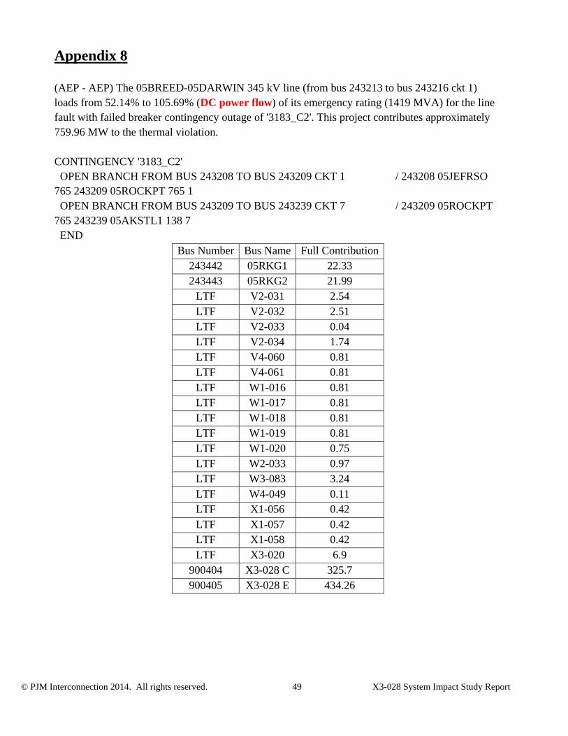
(AEP - AEP) The 05BREED-05DARWIN 345 kV line (from bus 243213 to bus 243216 ckt 1) loads from 52.14% to 105.69% (DC power flow) of its emergency rating (1419 MVA) for the line fault with failed breaker contingency outage of '3183_C2'. This project contributes approximately 759.96 MW to the thermal violation. CONTINGENCY '3183_C2' OPEN BRANCH FROM BUS 243208 TO BUS 243209 CKT 1 / 243208 05JEFRSO 765 243209 05ROCKPT 765 1 OPEN BRANCH FROM BUS 243209 TO BUS 243239 CKT 7 / 243209 05ROCKPT 765 243239 05AKSTL1 138 7 END
Bus Number Bus Name Full Contribution243442 05RKG1 22.33 243443 05RKG2 21.99
LTF V2-031 2.54 LTF V2-032 2.51 LTF V2-033 0.04 LTF V2-034 1.74 LTF V4-060 0.81 LTF V4-061 0.81 LTF W1-016 0.81 LTF W1-017 0.81 LTF W1-018 0.81 LTF W1-019 0.81 LTF W1-020 0.75 LTF W2-033 0.97 LTF W3-083 3.24 LTF W4-049 0.11 LTF X1-056 0.42 LTF X1-057 0.42 LTF X1-058 0.42 LTF X3-020 6.9
900404 X3-028 C 325.7 900405 X3-028 E 434.26

© PJM Interconnection 2014. All rights reserved. 50 X3-028 System Impact Study Report
Appendix 9
(AEP - AEP) The 05DARWIN-05EUGENE 345 kV line (from bus 243216 to bus 243221 ckt 1) loads from 52.79% to 106.44% (DC power flow) of its emergency rating (1419 MVA) for the line fault with failed breaker contingency outage of '2930_C2'. This project contributes approximately 761.25 MW to the thermal violation. CONTINGENCY '2930_C2' OPEN BRANCH FROM BUS 243208 TO BUS 243209 CKT 1 / 243208 05JEFRSO 765 243209 05ROCKPT 765 1 OPEN BRANCH FROM BUS 243208 TO BUS 248000 CKT 1 / 243208 05JEFRSO 765 248000 06CLIFTY 345 1 END
Bus Number Bus Name Full Contribution243442 05RKG1 22.37 243443 05RKG2 22.03
LTF V2-031 2.56 LTF V2-032 2.52 LTF V2-033 0.04 LTF V2-034 1.74 LTF V4-060 0.81 LTF V4-061 0.81 LTF W1-016 0.81 LTF W1-017 0.81 LTF W1-018 0.81 LTF W1-019 0.81 LTF W1-020 0.75 LTF W2-033 1.46 LTF W3-083 3.26 LTF W4-049 0.12 LTF X1-056 0.48 LTF X1-057 0.48 LTF X1-058 0.48 LTF X3-020 6.95
900404 X3-028 C 326.25 900405 X3-028 E 435.
© PJM Interconnection 2014. All rights reserved. 51 X3-028 System Impact Study Report
Appendix 10
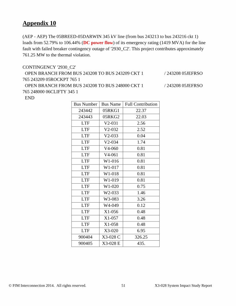
(AEP - AEP) The 05BREED-05DARWIN 345 kV line (from bus 243213 to bus 243216 ckt 1) loads from 52.79% to 106.44% (DC power flow) of its emergency rating (1419 MVA) for the line fault with failed breaker contingency outage of '2930_C2'. This project contributes approximately 761.25 MW to the thermal violation. CONTINGENCY '2930_C2' OPEN BRANCH FROM BUS 243208 TO BUS 243209 CKT 1 / 243208 05JEFRSO 765 243209 05ROCKPT 765 1 OPEN BRANCH FROM BUS 243208 TO BUS 248000 CKT 1 / 243208 05JEFRSO 765 248000 06CLIFTY 345 1 END
Bus Number Bus Name Full Contribution243442 05RKG1 22.37 243443 05RKG2 22.03
LTF V2-031 2.56 LTF V2-032 2.52 LTF V2-033 0.04 LTF V2-034 1.74 LTF V4-060 0.81 LTF V4-061 0.81 LTF W1-016 0.81 LTF W1-017 0.81 LTF W1-018 0.81 LTF W1-019 0.81 LTF W1-020 0.75 LTF W2-033 1.46 LTF W3-083 3.26 LTF W4-049 0.12 LTF X1-056 0.48 LTF X1-057 0.48 LTF X1-058 0.48 LTF X3-020 6.95
900404 X3-028 C 326.25 900405 X3-028 E 435.
© PJM Interconnection 2014. All rights reserved. 52 X3-028 System Impact Study Report
Appendix 11
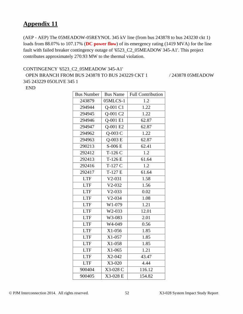
(AEP - AEP) The 05MEADOW-05REYNOL 345 kV line (from bus 243878 to bus 243230 ckt 1) loads from 88.07% to 107.17% (DC power flow) of its emergency rating (1419 MVA) for the line fault with failed breaker contingency outage of '6523_C2_05MEADOW 345-A1'. This project contributes approximately 270.93 MW to the thermal violation. CONTINGENCY '6523_C2_05MEADOW 345-A1' OPEN BRANCH FROM BUS 243878 TO BUS 243229 CKT 1 / 243878 05MEADOW 345 243229 05OLIVE 345 1 END
Bus Number Bus Name Full Contribution243879 05MLCS-1 1.2 294944 Q-001 C1 1.22 294945 Q-001 C2 1.22 294946 Q-001 E1 62.87 294947 Q-001 E2 62.87 294962 Q-003 C 1.22 294963 Q-003 E 62.87 290213 S-006 E 62.41 292412 T-126 C 1.2 292413 T-126 E 61.64 292416 T-127 C 1.2 292417 T-127 E 61.64
LTF V2-031 1.58 LTF V2-032 1.56 LTF V2-033 0.02 LTF V2-034 1.08 LTF W1-079 1.21 LTF W2-033 12.01 LTF W3-083 2.01 LTF W4-049 0.56 LTF X1-056 1.85 LTF X1-057 1.85 LTF X1-058 1.85 LTF X1-065 1.21 LTF X2-042 43.47 LTF X3-020 4.44
900404 X3-028 C 116.12 900405 X3-028 E 154.82

© PJM Interconnection 2014. All rights reserved. 53 X3-028 System Impact Study Report

© PJM Interconnection 2014. All rights reserved. 54 X3-028 System Impact Study Report
Appendix 12
(AEP - AEP) The 05DARWIN-05EUGENE 345 kV line (from bus 243216 to bus 243221 ckt 1) loads from 53.78% to 107.11% (DC power flow) of its emergency rating (1419 MVA) for the line fault with failed breaker contingency outage of '2929_C2'. This project contributes approximately 756.73 MW to the thermal violation. CONTINGENCY '2929_C2' OPEN BRANCH FROM BUS 243207 TO BUS 243208 CKT 1 / 243207 05GRNTWN 765 243208 05JEFRSO 765 1 OPEN BRANCH FROM BUS 243208 TO BUS 243209 CKT 1 / 243208 05JEFRSO 765 243209 05ROCKPT 765 1 END
Bus Number Bus Name Full Contribution243442 05RKG1 22.23 243443 05RKG2 21.9
LTF V2-031 2.46 LTF V2-032 2.43 LTF V2-033 0.04 LTF V2-034 1.68 LTF V4-060 0.74 LTF V4-061 0.74 LTF W1-016 0.74 LTF W1-017 0.74 LTF W1-018 0.74 LTF W1-019 0.74 LTF W1-020 0.68 LTF W2-033 1.82 LTF W3-083 3.13 LTF W4-049 0.14 LTF X1-056 0.44 LTF X1-057 0.44 LTF X1-058 0.44 LTF X3-020 6.68
900404 X3-028 C 324.32 900405 X3-028 E 432.42

© PJM Interconnection 2014. All rights reserved. 55 X3-028 System Impact Study Report
Appendix 13
(AEP - AEP) The 05BREED-05DARWIN 345 kV line (from bus 243213 to bus 243216 ckt 1) loads from 53.78% to 107.11% (DC power flow) of its emergency rating (1419 MVA) for the line fault with failed breaker contingency outage of '2929_C2'. This project contributes approximately 756.73 MW to the thermal violation. CONTINGENCY '2929_C2' OPEN BRANCH FROM BUS 243207 TO BUS 243208 CKT 1 / 243207 05GRNTWN 765 243208 05JEFRSO 765 1 OPEN BRANCH FROM BUS 243208 TO BUS 243209 CKT 1 / 243208 05JEFRSO 765 243209 05ROCKPT 765 1 END
Bus Number Bus Name Full Contribution243442 05RKG1 22.23 243443 05RKG2 21.9
LTF V2-031 2.46 LTF V2-032 2.43 LTF V2-033 0.04 LTF V2-034 1.68 LTF V4-060 0.74 LTF V4-061 0.74 LTF W1-016 0.74 LTF W1-017 0.74 LTF W1-018 0.74 LTF W1-019 0.74 LTF W1-020 0.68 LTF W2-033 1.82 LTF W3-083 3.13 LTF W4-049 0.14 LTF X1-056 0.44 LTF X1-057 0.44 LTF X1-058 0.44 LTF X3-020 6.68
900404 X3-028 C 324.32 900405 X3-028 E 432.42

© PJM Interconnection 2014. All rights reserved. 56 X3-028 System Impact Study Report
Appendix 14
(AEP - AEP) The 05BREED-05DARWIN 345 kV line (from bus 243213 to bus 243216 ckt 1) loads from 76.12% to 109.63% (DC power flow) of its emergency rating (972 MVA) for the single line contingency outage of '05JEFRSO _05ROCKPT _122'. This project contributes approximately 325.7 MW to the thermal violation. CONTINGENCY '05JEFRSO _05ROCKPT _122' DISCONNECT BRANCH FROM BUS 243208 TO BUS 243209 CKT 1 /* 765/765KV, AREA 205/205. END
Bus Number Bus Name Full Contribution243442 05RKG1 22.33 243443 05RKG2 21.99
LTF V2-031 2.54 LTF V2-032 2.51 LTF V2-033 0.04 LTF V2-034 1.74 LTF V4-060 0.81 LTF V4-061 0.81 LTF W1-016 0.81 LTF W1-017 0.81 LTF W1-018 0.81 LTF W1-019 0.81 LTF W1-020 0.75 LTF W2-033 0.97 LTF W3-083 3.24 LTF W4-049 0.11 LTF X1-056 0.42 LTF X1-057 0.42 LTF X1-058 0.42 LTF X3-020 6.9
900404 X3-028 C 325.7
© PJM Interconnection 2014. All rights reserved. 57 X3-028 System Impact Study Report
Appendix 15
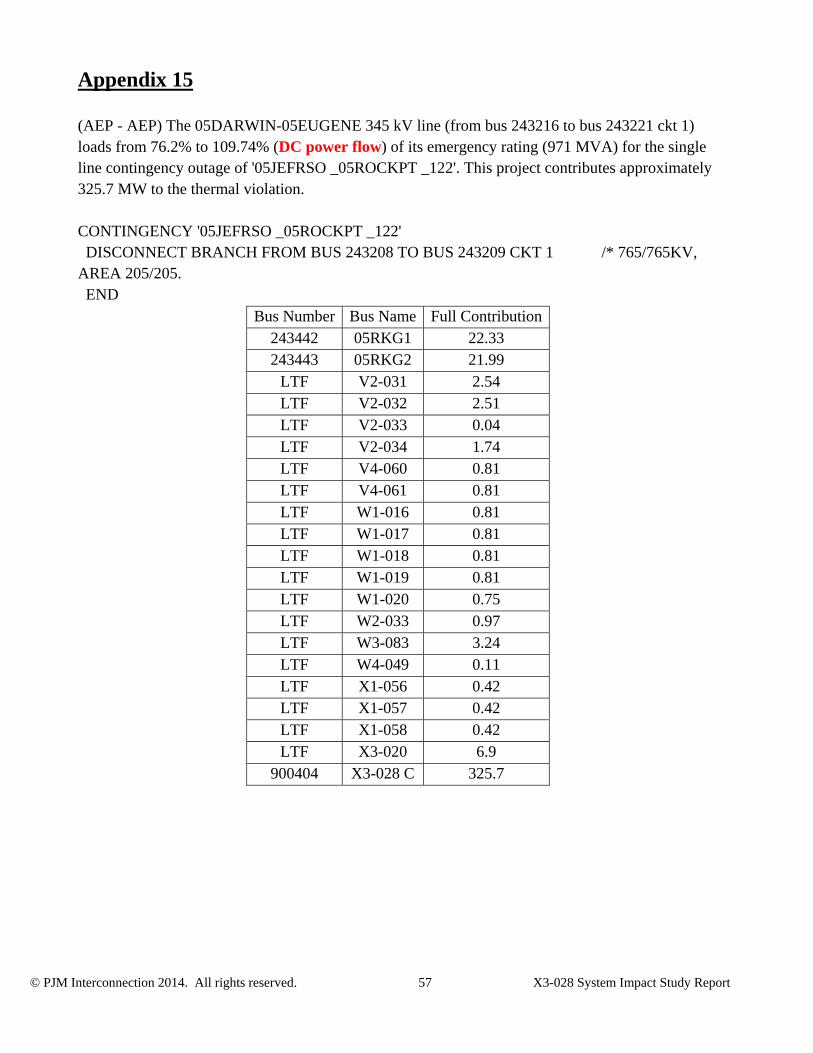
(AEP - AEP) The 05DARWIN-05EUGENE 345 kV line (from bus 243216 to bus 243221 ckt 1) loads from 76.2% to 109.74% (DC power flow) of its emergency rating (971 MVA) for the single line contingency outage of '05JEFRSO _05ROCKPT _122'. This project contributes approximately 325.7 MW to the thermal violation. CONTINGENCY '05JEFRSO _05ROCKPT _122' DISCONNECT BRANCH FROM BUS 243208 TO BUS 243209 CKT 1 /* 765/765KV, AREA 205/205. END
Bus Number Bus Name Full Contribution243442 05RKG1 22.33 243443 05RKG2 21.99
LTF V2-031 2.54 LTF V2-032 2.51 LTF V2-033 0.04 LTF V2-034 1.74 LTF V4-060 0.81 LTF V4-061 0.81 LTF W1-016 0.81 LTF W1-017 0.81 LTF W1-018 0.81 LTF W1-019 0.81 LTF W1-020 0.75 LTF W2-033 0.97 LTF W3-083 3.24 LTF W4-049 0.11 LTF X1-056 0.42 LTF X1-057 0.42 LTF X1-058 0.42 LTF X3-020 6.9
900404 X3-028 C 325.7
© PJM Interconnection 2014. All rights reserved. 58 X3-028 System Impact Study Report
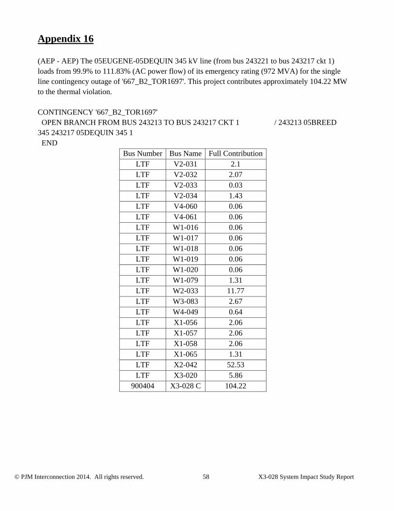
Appendix 16
(AEP - AEP) The 05EUGENE-05DEQUIN 345 kV line (from bus 243221 to bus 243217 ckt 1) loads from 99.9% to 111.83% (AC power flow) of its emergency rating (972 MVA) for the single line contingency outage of '667_B2_TOR1697'. This project contributes approximately 104.22 MW to the thermal violation. CONTINGENCY '667_B2_TOR1697' OPEN BRANCH FROM BUS 243213 TO BUS 243217 CKT 1 / 243213 05BREED 345 243217 05DEQUIN 345 1 END
Bus Number Bus Name Full ContributionLTF V2-031 2.1 LTF V2-032 2.07 LTF V2-033 0.03 LTF V2-034 1.43 LTF V4-060 0.06 LTF V4-061 0.06 LTF W1-016 0.06 LTF W1-017 0.06 LTF W1-018 0.06 LTF W1-019 0.06 LTF W1-020 0.06 LTF W1-079 1.31 LTF W2-033 11.77 LTF W3-083 2.67 LTF W4-049 0.64 LTF X1-056 2.06 LTF X1-057 2.06 LTF X1-058 2.06 LTF X1-065 1.31 LTF X2-042 52.53 LTF X3-020 5.86
900404 X3-028 C 104.22
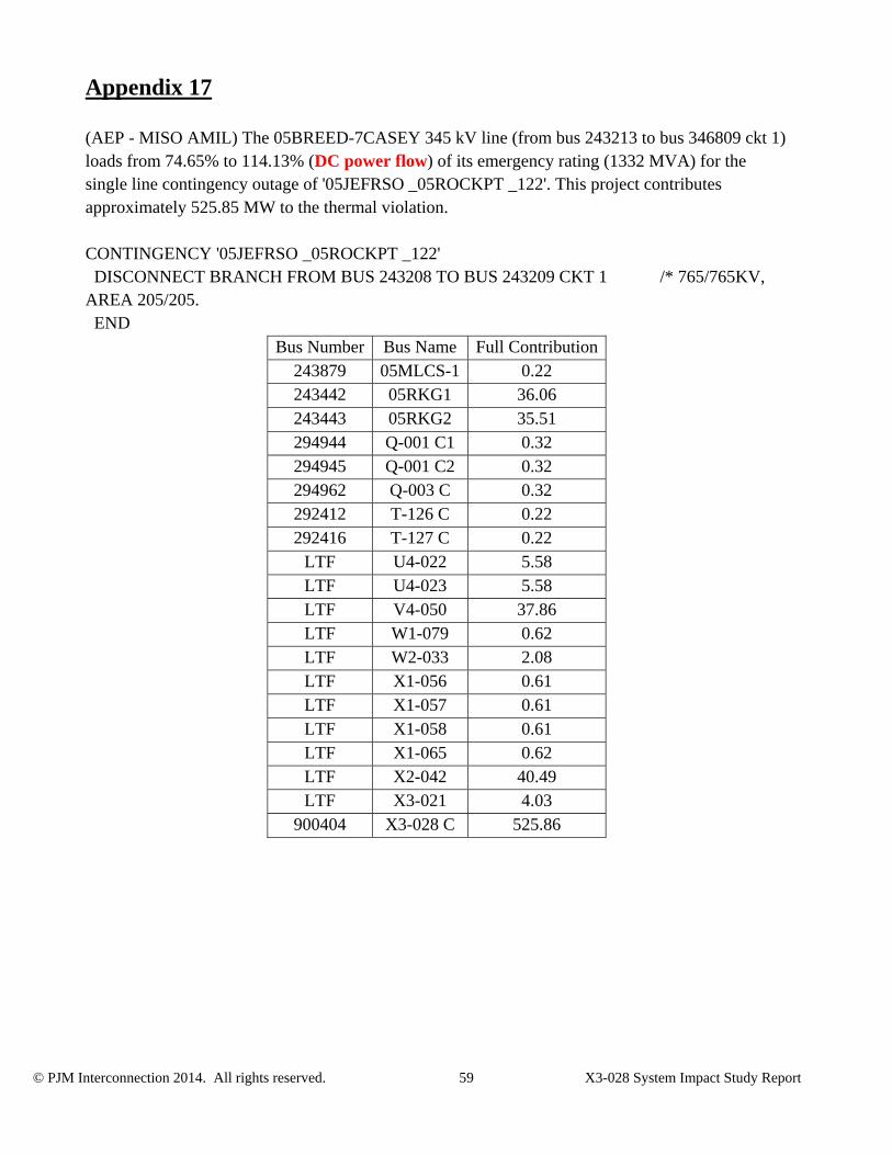
© PJM Interconnection 2014. All rights reserved. 59 X3-028 System Impact Study Report
Appendix 17
(AEP - MISO AMIL) The 05BREED-7CASEY 345 kV line (from bus 243213 to bus 346809 ckt 1) loads from 74.65% to 114.13% (DC power flow) of its emergency rating (1332 MVA) for the single line contingency outage of '05JEFRSO _05ROCKPT _122'. This project contributes approximately 525.85 MW to the thermal violation. CONTINGENCY '05JEFRSO _05ROCKPT _122' DISCONNECT BRANCH FROM BUS 243208 TO BUS 243209 CKT 1 /* 765/765KV, AREA 205/205. END
Bus Number Bus Name Full Contribution243879 05MLCS-1 0.22 243442 05RKG1 36.06 243443 05RKG2 35.51 294944 Q-001 C1 0.32 294945 Q-001 C2 0.32 294962 Q-003 C 0.32 292412 T-126 C 0.22 292416 T-127 C 0.22
LTF U4-022 5.58 LTF U4-023 5.58 LTF V4-050 37.86 LTF W1-079 0.62 LTF W2-033 2.08 LTF X1-056 0.61 LTF X1-057 0.61 LTF X1-058 0.61 LTF X1-065 0.62 LTF X2-042 40.49 LTF X3-021 4.03
900404 X3-028 C 525.86
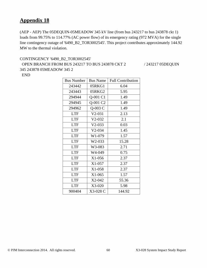
© PJM Interconnection 2014. All rights reserved. 60 X3-028 System Impact Study Report
Appendix 18
(AEP - AEP) The 05DEQUIN-05MEADOW 345 kV line (from bus 243217 to bus 243878 ckt 1) loads from 99.75% to 114.77% (AC power flow) of its emergency rating (972 MVA) for the single line contingency outage of '6490_B2_TOR3002545'. This project contributes approximately 144.92 MW to the thermal violation. CONTINGENCY '6490_B2_TOR3002545' OPEN BRANCH FROM BUS 243217 TO BUS 243878 CKT 2 / 243217 05DEQUIN 345 243878 05MEADOW 345 2 END
Bus Number Bus Name Full Contribution243442 05RKG1 6.04 243443 05RKG2 5.95 294944 Q-001 C1 1.49 294945 Q-001 C2 1.49 294962 Q-003 C 1.49
LTF V2-031 2.13 LTF V2-032 2.1 LTF V2-033 0.03 LTF V2-034 1.45 LTF W1-079 1.57 LTF W2-033 15.28 LTF W3-083 2.71 LTF W4-049 0.75 LTF X1-056 2.37 LTF X1-057 2.37 LTF X1-058 2.37 LTF X1-065 1.57 LTF X2-042 55.36 LTF X3-020 5.98
900404 X3-028 C 144.92

© PJM Interconnection 2014. All rights reserved. 61 X3-028 System Impact Study Report
Appendix 19
(AEP - AEP) The 05DEQUIN-05MEADOW 345 kV line (from bus 243217 to bus 243878 ckt 2) loads from 99.85% to 114.88% (AC power flow) of its emergency rating (971 MVA) for the single line contingency outage of '6472_B2_TOR15258'. This project contributes approximately 144.92 MW to the thermal violation. CONTINGENCY '6472_B2_TOR15258' OPEN BRANCH FROM BUS 243217 TO BUS 243878 CKT 1 / 243217 05DEQUIN 345 243878 05MEADOW 345 1 END
Bus Number Bus Name Full Contribution243442 05RKG1 6.04 243443 05RKG2 5.95 294944 Q-001 C1 1.49 294945 Q-001 C2 1.49 294962 Q-003 C 1.49
LTF V2-031 2.13 LTF V2-032 2.1 LTF V2-033 0.03 LTF V2-034 1.45 LTF W1-079 1.57 LTF W2-033 15.28 LTF W3-083 2.71 LTF W4-049 0.75 LTF X1-056 2.37 LTF X1-057 2.37 LTF X1-058 2.37 LTF X1-065 1.57 LTF X2-042 55.36 LTF X3-020 5.98
900404 X3-028 C 144.92
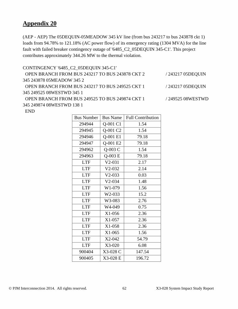
© PJM Interconnection 2014. All rights reserved. 62 X3-028 System Impact Study Report
Appendix 20
(AEP - AEP) The 05DEQUIN-05MEADOW 345 kV line (from bus 243217 to bus 243878 ckt 1) loads from 94.78% to 121.18% (AC power flow) of its emergency rating (1304 MVA) for the line fault with failed breaker contingency outage of '6485_C2_05DEQUIN 345-C1'. This project contributes approximately 344.26 MW to the thermal violation. CONTINGENCY '6485_C2_05DEQUIN 345-C1' OPEN BRANCH FROM BUS 243217 TO BUS 243878 CKT 2 / 243217 05DEQUIN 345 243878 05MEADOW 345 2 OPEN BRANCH FROM BUS 243217 TO BUS 249525 CKT 1 / 243217 05DEQUIN 345 249525 08WESTWD 345 1 OPEN BRANCH FROM BUS 249525 TO BUS 249874 CKT 1 / 249525 08WESTWD 345 249874 08WESTWD 138 1 END
Bus Number Bus Name Full Contribution294944 Q-001 C1 1.54 294945 Q-001 C2 1.54 294946 Q-001 E1 79.18 294947 Q-001 E2 79.18 294962 Q-003 C 1.54 294963 Q-003 E 79.18
LTF V2-031 2.17 LTF V2-032 2.14 LTF V2-033 0.03 LTF V2-034 1.48 LTF W1-079 1.56 LTF W2-033 15.2 LTF W3-083 2.76 LTF W4-049 0.75 LTF X1-056 2.36 LTF X1-057 2.36 LTF X1-058 2.36 LTF X1-065 1.56 LTF X2-042 54.79 LTF X3-020 6.08
900404 X3-028 C 147.54 900405 X3-028 E 196.72
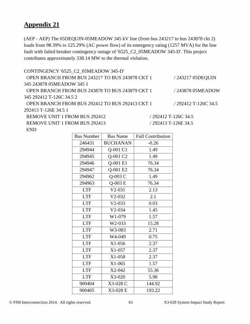
© PJM Interconnection 2014. All rights reserved. 63 X3-028 System Impact Study Report
Appendix 21
(AEP - AEP) The 05DEQUIN-05MEADOW 345 kV line (from bus 243217 to bus 243878 ckt 2) loads from 98.39% to 125.29% (AC power flow) of its emergency rating (1257 MVA) for the line fault with failed breaker contingency outage of '6525_C2_05MEADOW 345-D'. This project contributes approximately 338.14 MW to the thermal violation. CONTINGENCY '6525_C2_05MEADOW 345-D' OPEN BRANCH FROM BUS 243217 TO BUS 243878 CKT 1 / 243217 05DEQUIN 345 243878 05MEADOW 345 1 OPEN BRANCH FROM BUS 243878 TO BUS 243879 CKT 1 / 243878 05MEADOW 345 292412 T-126C 34.5 2 OPEN BRANCH FROM BUS 292412 TO BUS 292413 CKT 1 / 292412 T-126C 34.5 292413 T-126E 34.5 1 REMOVE UNIT 1 FROM BUS 292412 / 292412 T-126C 34.5 REMOVE UNIT 1 FROM BUS 292413 / 292413 T-126E 34.5 END
Bus Number Bus Name Full Contribution246431 BUCHANAN -0.26 294944 Q-001 C1 1.49 294945 Q-001 C2 1.49 294946 Q-001 E1 76.34 294947 Q-001 E2 76.34 294962 Q-003 C 1.49 294963 Q-003 E 76.34
LTF V2-031 2.13 LTF V2-032 2.1 LTF V2-033 0.03 LTF V2-034 1.45 LTF W1-079 1.57 LTF W2-033 15.28 LTF W3-083 2.71 LTF W4-049 0.75 LTF X1-056 2.37 LTF X1-057 2.37 LTF X1-058 2.37 LTF X1-065 1.57 LTF X2-042 55.36 LTF X3-020 5.98
900404 X3-028 C 144.92 900405 X3-028 E 193.22

© PJM Interconnection 2014. All rights reserved. 64 X3-028 System Impact Study Report

© PJM Interconnection 2014. All rights reserved. 65 X3-028 System Impact Study Report
Appendix 22
(AEP - AEP) The 05DEQUIN-05MEADOW 345 kV line (from bus 243217 to bus 243878 ckt 2) loads from 98.32% to 125.71% (AC power flow) of its emergency rating (1257 MVA) for the line fault with failed breaker contingency outage of '4704_C2_05DEQUIN 345-B1'. This project contributes approximately 344.26 MW to the thermal violation. CONTINGENCY '4704_C2_05DEQUIN 345-B1' OPEN BRANCH FROM BUS 243217 TO BUS 243878 CKT 1 / 243217 05DEQUIN 345 243878 05MEADOW 345 1 OPEN BRANCH FROM BUS 243217 TO BUS 249525 CKT 1 / 243217 05DEQUIN 345 249525 08WESTWD 345 1 OPEN BRANCH FROM BUS 249525 TO BUS 249874 CKT 1 / 249525 08WESTWD 345 249874 08WESTWD 138 1 END
Bus Number Bus Name Full Contribution294944 Q-001 C1 1.54 294945 Q-001 C2 1.54 294946 Q-001 E1 79.18 294947 Q-001 E2 79.18 294962 Q-003 C 1.54 294963 Q-003 E 79.18
LTF V2-031 2.17 LTF V2-032 2.14 LTF V2-033 0.03 LTF V2-034 1.48 LTF W1-079 1.56 LTF W2-033 15.2 LTF W3-083 2.76 LTF W4-049 0.75 LTF X1-056 2.36 LTF X1-057 2.36 LTF X1-058 2.36 LTF X1-065 1.56 LTF X2-042 54.79 LTF X3-020 6.08
900404 X3-028 C 147.54 900405 X3-028 E 196.72
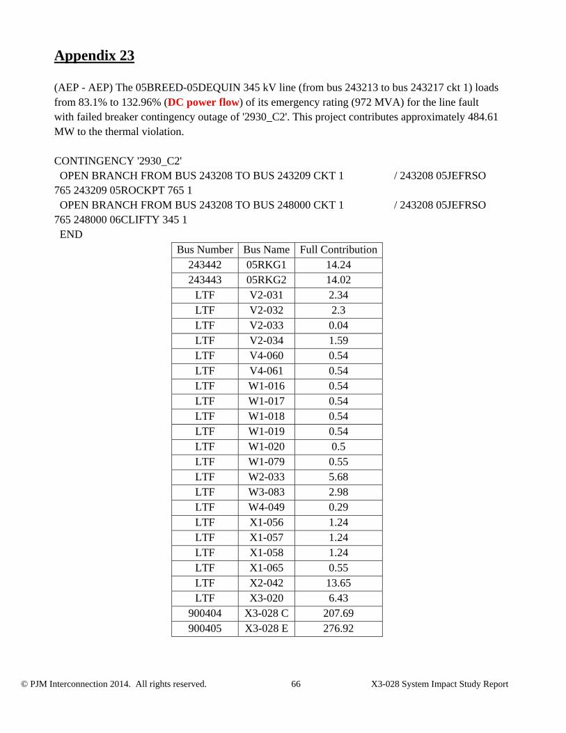
© PJM Interconnection 2014. All rights reserved. 66 X3-028 System Impact Study Report
Appendix 23
(AEP - AEP) The 05BREED-05DEQUIN 345 kV line (from bus 243213 to bus 243217 ckt 1) loads from 83.1% to 132.96% (DC power flow) of its emergency rating (972 MVA) for the line fault with failed breaker contingency outage of '2930_C2'. This project contributes approximately 484.61 MW to the thermal violation. CONTINGENCY '2930_C2' OPEN BRANCH FROM BUS 243208 TO BUS 243209 CKT 1 / 243208 05JEFRSO 765 243209 05ROCKPT 765 1 OPEN BRANCH FROM BUS 243208 TO BUS 248000 CKT 1 / 243208 05JEFRSO 765 248000 06CLIFTY 345 1 END
Bus Number Bus Name Full Contribution243442 05RKG1 14.24 243443 05RKG2 14.02
LTF V2-031 2.34 LTF V2-032 2.3 LTF V2-033 0.04 LTF V2-034 1.59 LTF V4-060 0.54 LTF V4-061 0.54 LTF W1-016 0.54 LTF W1-017 0.54 LTF W1-018 0.54 LTF W1-019 0.54 LTF W1-020 0.5 LTF W1-079 0.55 LTF W2-033 5.68 LTF W3-083 2.98 LTF W4-049 0.29 LTF X1-056 1.24 LTF X1-057 1.24 LTF X1-058 1.24 LTF X1-065 0.55 LTF X2-042 13.65 LTF X3-020 6.43
900404 X3-028 C 207.69 900405 X3-028 E 276.92

© PJM Interconnection 2014. All rights reserved. 67 X3-028 System Impact Study Report
Appendix 24
(AEP - AEP) The 05BREED-05DEQUIN 345 kV line (from bus 243213 to bus 243217 ckt 1) loads from 84.42% to 133.37% (DC power flow) of its emergency rating (972 MVA) for the line fault with failed breaker contingency outage of '2929_C2'. This project contributes approximately 475.79 MW to the thermal violation. CONTINGENCY '2929_C2' OPEN BRANCH FROM BUS 243207 TO BUS 243208 CKT 1 / 243207 05GRNTWN 765 243208 05JEFRSO 765 1 OPEN BRANCH FROM BUS 243208 TO BUS 243209 CKT 1 / 243208 05JEFRSO 765 243209 05ROCKPT 765 1 END
Bus Number Bus Name Full Contribution243442 05RKG1 13.98 243443 05RKG2 13.77
LTF V2-031 2.17 LTF V2-032 2.13 LTF V2-033 0.03 LTF V2-034 1.48 LTF V4-060 0.41 LTF V4-061 0.41 LTF W1-016 0.41 LTF W1-017 0.41 LTF W1-018 0.41 LTF W1-019 0.41 LTF W1-020 0.38 LTF W1-079 0.49 LTF W2-033 5.82 LTF W3-083 2.76 LTF W4-049 0.33 LTF X1-056 1.13 LTF X1-057 1.13 LTF X1-058 1.13 LTF X1-065 0.49 LTF X2-042 11.84 LTF X3-020 5.95
900404 X3-028 C 203.91 900405 X3-028 E 271.88

© PJM Interconnection 2014. All rights reserved. 68 X3-028 System Impact Study Report
Appendix 25
(AEP - MISO AMIL) The 05BREED-7CASEY 345 kV line (from bus 243213 to bus 346809 ckt 1) loads from 72.97% to 156.6% (DC power flow) of its emergency rating (1466 MVA) for the line fault with failed breaker contingency outage of '2929_C2'. This project contributes approximately 1225.98 MW to the thermal violation. CONTINGENCY '2929_C2' OPEN BRANCH FROM BUS 243207 TO BUS 243208 CKT 1 / 243207 05GRNTWN 765 243208 05JEFRSO 765 1 OPEN BRANCH FROM BUS 243208 TO BUS 243209 CKT 1 / 243208 05JEFRSO 765 243209 05ROCKPT 765 1 END
Bus Number Bus Name Full Contribution243442 05RKG1 36.03 243443 05RKG2 35.48 294946 Q-001 E1 16.26 294947 Q-001 E2 16.26 294963 Q-003 E 16.26 290213 S-006 E 11.19 292413 T-126 E 11.06 292417 T-127 E 11.06
LTF U4-022 5.58 LTF U4-023 5.58 LTF V4-050 37.95 LTF W1-079 0.64 LTF W2-033 2.35 LTF X1-056 0.62 LTF X1-057 0.62 LTF X1-058 0.62 LTF X1-065 0.64 LTF X2-042 40.37 LTF X3-021 3.74
900404 X3-028 C 525.42 900405 X3-028 E 700.56
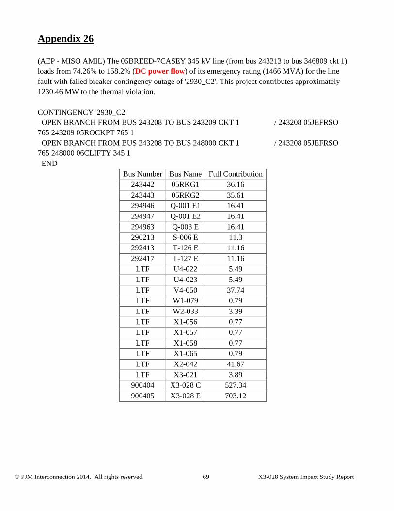
© PJM Interconnection 2014. All rights reserved. 69 X3-028 System Impact Study Report
Appendix 26
(AEP - MISO AMIL) The 05BREED-7CASEY 345 kV line (from bus 243213 to bus 346809 ckt 1) loads from 74.26% to 158.2% (DC power flow) of its emergency rating (1466 MVA) for the line fault with failed breaker contingency outage of '2930_C2'. This project contributes approximately 1230.46 MW to the thermal violation. CONTINGENCY '2930_C2' OPEN BRANCH FROM BUS 243208 TO BUS 243209 CKT 1 / 243208 05JEFRSO 765 243209 05ROCKPT 765 1 OPEN BRANCH FROM BUS 243208 TO BUS 248000 CKT 1 / 243208 05JEFRSO 765 248000 06CLIFTY 345 1 END
Bus Number Bus Name Full Contribution243442 05RKG1 36.16 243443 05RKG2 35.61 294946 Q-001 E1 16.41 294947 Q-001 E2 16.41 294963 Q-003 E 16.41 290213 S-006 E 11.3 292413 T-126 E 11.16 292417 T-127 E 11.16
LTF U4-022 5.49 LTF U4-023 5.49 LTF V4-050 37.74 LTF W1-079 0.79 LTF W2-033 3.39 LTF X1-056 0.77 LTF X1-057 0.77 LTF X1-058 0.77 LTF X1-065 0.79 LTF X2-042 41.67 LTF X3-021 3.89
900404 X3-028 C 527.34 900405 X3-028 E 703.12