pizza hut, parcel 2, seneca street, buffalo, erie county
TRANSCRIPT

URS Corporation36 East 7
thStreet, Suite 2300
Cincinnati, Ohio 45202Tel: 513.651.3440Fax: 513.651.3452
PIZZA HUT, PARCEL 2, SENECA STREET,BUFFALO, ERIE COUNTY NEW YORK
SITE MANAGEMENT PLANNYSDEC VCP SITE NUMBER: V-00370-9
Prepared for:GE CAPITAL FRANCHISE FINANCECORPORATION8377 HARTFORD DRIVE, SUITE 200SCOTTSDALE, ARIZONA 84255
JOB NO.: 14964473MAY 25, 2011

URS Corporation 36 East 7
th Street, Suite 2300
Cincinnati, Ohio 45202 Tel: 513.651.3440 Fax: 513.651.3452
June 8, 2011
David P. Locey
Environmental Engineer I
Division of Environmental Remediation
New York State Dept. of Environmental Conservation - Region 9
270 Michigan Avenue
Buffalo, New York 14203-2999
Subject: Final Site Management Plan
Parcel 2, Seneca St., Buffalo, New York
Voluntary Cleanup Agreement V-00370-9
Dear Mr. Locey:
On behalf GE Capital Franchise Finance Corporation (“GEFF”), URS is submitting one hard
copy and one electronic copy of the final Site Management Plan (SMP) for the
aforementioned property. The SMP outlines the remedial actions completed at the Site,
current Site conditions, and the accepted plan for post-closure monitoring and maintenance.
The final SMP has been revised to incorporate the New York State Department of
Environmental Conservation (NYSDEC) comments on the original draft SMP dated
December 7, 2010 and the revised SMP dated April 14, 2011, and was approved by NYSDEC
in their letter dated May 23, 2011. Additionally, a boundary survey map has been included in
Appendix B of the SMP with the Declaration of Covenants and Restrictions, and a
certification statement sealed by a New York State Professional Engineer has been enclosed in
the front of this document.
Submittal of this SMP completes all the project requirements in accordance with the
Voluntary Cleanup Agreement (VCA) dated July 10, 2001, and should allow the NYSDEC to
issue an Assignable Release and Covenant Not to Sue (CNS) for the Site.

REVISIONS TO FINAL APPROVED SITE MANAGEMENT PLAN:
Revision # Submitted Date Summary of Revision DEC Approval Date

CONTENTS
SECTION PAGE
ACRONYMS AND ABBREVIATIONS.............................................................................................. i
1.0 INTRODUCTION AND DESCRIPTION OF REMEDIAL PROGRAM................................. 11.1 INTRODUCTION.................................................................................................... 1
1.1.1 General ...................................................................................................... 11.1.2 Purpose ...................................................................................................... 21.1.3 Revisions.................................................................................................... 4
1.2 SITE BACKGROUND............................................................................................. 41.2.1 Site Location and Description..................................................................... 41.2.2 Site History ................................................................................................ 51.2.3 Geologic Conditions ................................................................................... 61.2.4 Hydrogeologic Conditions .......................................................................... 7
1.3 SUMMARY OF SITE INVESTIGATION (SI) FINDINGS...................................... 81.3.1 Standards, Criteria, and Guidelines (SCGs)................................................ 81.3.2 Soil ............................................................................................................ 101.3.3 Site-Related Groundwater........................................................................... 101.3.4 Site-Related Soil Vapor Intrusion (SVI)...................................................... 111.3.5 Underground Storage Tanks (USTs)........................................................... 12
1.4 SUMMARY OF REMEDIATION ACTIONS .......................................................... 121.4.1 Removal of Contaminated Materials from the Site...................................... 131.4.2 Site-Related Treatment Systems ................................................................. 141.4.3 Remaining Contamination.......................................................................... 16
2.0 ENGINEERING AND INSTITUTIONAL CONTROL PLAN ............................................... 192.1 INTRODUCTION.................................................................................................... 19
2.1.1 General ...................................................................................................... 192.1.2 Purpose ...................................................................................................... 19
2.2 ENGINEERING CONTROLS.................................................................................. 192.2.1 Engineering Control Systems ..................................................................... 192.2.2 Criteria for Completion of Remediation/Termination of Remedial
Systems ...................................................................................................... 212.3 INSTITUTIONAL CONTROLS (ICS) ..................................................................... 23
2.3.1 Excavation Work Plan (EWP) .................................................................... 242.3.2 Soil Vapor Intrusion (SVI) Evaluation........................................................ 25
2.4 INSPECTION AND NOTIFICATIONS................................................................... 262.4.1 Inspections ................................................................................................. 262.4.2 Notifications............................................................................................... 26
2.5 CONTINGENCY PLAN.......................................................................................... 272.5.1 Emergency Telephone Numbers ................................................................. 272.5.2 Map and Directions to Nearest Health Facility............................................ 282.5.3 Response Procedures .................................................................................. 29
3.0 SITE MONITORING PLAN.................................................................................................. 313.1 INTRODUCTION.................................................................................................... 31
3.1.1 General ...................................................................................................... 313.1.2 Purpose and Schedule................................................................................. 31
3.2 SOIL COVER SYSTEM MONITORING................................................................. 333.3 MEDIA MONITORING PROGRAM....................................................................... 33
3.3.1 Groundwater Progress Monitoring and Confirmatory Sampling.................. 343.3.2 Soil Vapor Intrusion (SVI) Monitoring....................................................... 37
3.4 SITE-WIDE INSPECTION...................................................................................... 383.5 MONITORING QUALITY ASSURANCE/QUALITY CONTROL (QA/QC)........... 383.6 MONITORING REPORTING REQUIREMENTS ................................................... 39
CONTENTS(Continued)
4.0 OPERATION AND MAINTENANCE (O&M) PLAN........................................................... 414.1 INTRODUCTION.................................................................................................... 41
5.0 INSPECTIONS, REPORTING, AND CERTIFICATIONS .................................................... 425.1 SITE INSPECTIONS............................................................................................... 42
5.1.1 Inspection Frequency.................................................................................. 425.1.2 Inspection Forms, Sampling Data, and Maintenance Reports...................... 425.1.3 Evaluation of Records and Reporting.......................................................... 42
5.2 CERTIFICATION, OF EC/ICS................................................................................ 435.3 PERIODIC REVIEW REPORT................................................................................ 445.4 CORRECTIVE MEASURES PLAN ........................................................................ 45
TABLES(follow text)
Number
1 GROUNDWATER ELEVATIONS2 ANALYTICAL RESULTS SUMMARY, SOIL SAMPLING – PRE-REMEDIAL ACTIVITIES
1999-20063 ANALYTICAL RESULTS SUMMARY, GROUNDWATER SAMPLING – SUPPLEMENTAL
INVESTIGATION JANUARY 6-13, 2006 EVENT4 SUMMARY OF COMPOUNDS DETECTED IN SOIL GAS AND INDOOR AIR CURRENT
VACANT BUILDING5 NEW YORK STATE STANDARDS, CRITERIA AND GUIDANCE (SCGs) FOR
COMPOUNDS OF CONCERN6 ANALYTICAL RESULTS SUMMARY, SOIL SAMPLING – POST-EXCAVATION
SAMPLING OCTOBER AND NOVEMBER 20037 ANALYTICAL RESULTS SUMMARY, GROUNDWATER SAMPLING SEPTEMBER 2000
TO AUGUST 20108 EMERGENCY CONTACT NUMBERS9 SITE-RELATED CONTACT NUMBERS10 MONITORING/INSPECTION SCHEDULE11 HAZARDOUS WASTE CHARACTERIZATION CRITERIA FOR WASTE WATER (AS OF
DECEMBER 2010)12 SCHEDULE OF MONITORING/INSPECTION REPORTS
FIGURES(follow tables)
Number
1 SITE VICINITY MAP2 SITE LAYOUT MAP SHOWING PRE-REMEDIAL SAMPLING LOCATIONS AND
HISTORIC ADDRESSES3 SITE LAYOUT MAP WITH CROSS-SECTION LOCATION4 CROSS-SECTION A-A’
CONTENTS(Continued)
5 SHALLOW POTENTIOMETRIC SURFACE MAP, JUNE 23, 2010
FIGURES(Continued)
Number
6 CHLORINATED VOLATILE ORGANIC COMPOUND (CVOCS) DISTRIBUTION INSHALLOW GROUNDWATER – JANUARY 2006
7 EXTENT OF EXCAVATION AND POST EXCAVATION SAMPLING LOCATIONS8 IN-SITU CHEMICAL OXIDATION (ISCO) SYSTEM LOCATION MAP9 SEPTEMBER 2007 INJECTION EVENT10 SEPTEMBER 2008 INJECTION EVENT11 NOVEMBER 2009 INJECTION EVENT12 CHLORINATED VOLATILE ORGANIC COMPOUND (CVOC) CONCENTRATIONS IN
SHALLOW GROUNDWATER, JANUARY 2005 TO AUGUST 201013 POST-REMEDIAL ACTION SOIL SAMPLE LOCATIONS – CHLORINATED VOLATILE
ORGANIC COMPOUNDS (CVOCS)14 POST-REMEDIAL ACTION SOIL SAMPLE LOCATIONS – POLYNUCLEAR AROMATIC
HYDROCARBONS (PAHS)15 CHLORINATED VOLATILE ORGANIC COMPOUND (CVOC) DISTRIBUTION IN
SHALLOW GROUNDWATER16 PLANNED GROUNDWATER MONITORING SYSTEM
APPENDICES(follow figures)
Appendix
A VOLUNTARY CLEANUP AGREEMENTB DECLARATION OF COVENANTS AND RESTRICTIONS (INCLUDING METES AND
BOUNDS)C EXCAVATION WORK PLAN, INCLUDING COMMUNITY AIR MONITORING PLAND HEALTH AND SAFETY PLANE SITE-WIDE INSPECTION FORMSF MONITORING WELL BORING AND CONSTRUCTION LOGSG GROUNDWATER MONITORING WELL SAMPLING LOG FORMH QUALITY ASSURANCE PROJECT PLAN

GEFF i Buffalo, NYNYSDEC VCP Site Number: V-00370-9 5/25/11Site Management Plan
ACRONYMS AND ABBREVIATIONS
ASP Analytical Services Protocolbgs Below Ground SurfaceºC Degrees CelsiusCAMP Community Air Monitoring PlanCFR Code of Federal Regulationscm/sec Centimeter per SecondCOCs Constituents of ConcernCRA Conestoga Rovers and AssociatesCVOCs Chlorinated Volatile Organic Compounds1,1-DCE 1,1-DichloroetheneCis-1,2-DCE Cis-1,2-DichloroetheneTrans-1,2-DCE Trans-1,2-DichloroetheneDUSR Data Usability Summary ReportECL Environ mental Conservation LawECs Engineering ControlsEDD Electronic Data DeliverableEIMS Environmental Information Management SystemEPA Environmental Protection AgencyESA Environmental Site AssessmentESI Environmental Site InvestigationEWP Excavation Work PlanFFCA Franchise Finance Corporation of America (merged with GEFF in 2001)FRC Fourth River Company of Pittsburg, PennsylvaniaGEFF GE Capital Franchise Finance CorporationHASP Health and Safety PlanHRC® Hydrogen-Releasing CompoundHVAC Heating, Ventilation, and Air ConditioningICs Institutional ControlsISCO In-Situ Chemical Oxidationmg/kg Milligrams per kilogram or parts per million (ppm) – Soil Unitsmg/L Milligrams per Liter or parts per million (ppm) – Groundwater UnitsNYCRR New York Codes, Rules, and RegulationsNYS New York StateNYSDEC New York State Department of Environmental ConservationNYSDOH New York State Department of HealthNYSDOT New York State Department of TransportationO&M Operation and MaintenanceORP Oxidation-Reduction PotentialOSHA Occupational Safety and Health AdministrationPAHs Polynuclear Aromatic Hydrocarbons

GEFF ii Buffalo, NYNYSDEC VCP Site Number: V-00370-9 5/25/11Site Management Plan
PCE TetrachloroethenePELs Permissible Exposure Limitsppb Parts per Billionppm Parts per MillionPRGs Preliminary Remediation GoalsQA/QC Quality Assurance/Quality ControlQAPP Quality Assurance Project PlanRA Report Remedial Action ReportRAOs Remedial Action ObjectivesRAS Remedial Action Selection ReportRAWP Remedial Action Work PlanSCGs Standards, Criteria, and GuidelinesSCOs Soil Clean-up ObjectivesSI Site InvestigationSI/FS Report Site Investigation Report and Feasibility Study ReportSMP Site Management PlanSSD Sub-slab DepressurizationSVE Soil Vapor ExtractionSVI Soil Vapor IntrusionSVOCs Semivolatile Organic CompoundsTAGM Technical Administrative Guidance MemorandumTCE TrichloroetheneTOGS Technical and Operations Guidance SeriesURS URS CorporationUSTs Underground Storage TanksVCA Voluntary Cleanup AgreementVCP Voluntary Cleanup ProgramVOCs Volatile Organic CompoundsZVI Zero-Valent Iron
GEFF 1 Buffalo, NYNYSDEC VCP Site Number: V-00370-9 5/25/11Site Management Plan
SITE MANAGEMENT PLAN (SMP)
1.0 INTRODUCTION AND DESCRIPTION OF REMEDIAL PROGRAM
1.1 INTRODUCTION
This document is an element of the remedial program at the commercial property referred to as
“Parcel 2,” 2137 Seneca Street, Buffalo, New York (hereinafter referred to as the “Site”) under
the New York State (NYS) Voluntary Cleanup Program (VCP) administered by New York State
Department of Environmental Conservation (NYSDEC). The Site was remediated pursuant to
NYSDEC approved work plans in accordance with Voluntary Cleanup Agreement (VCA) # B9-
0580-00-07, Site # V-00370-9 between NYSDEC and Franchise Finance Corporation of America
(FFCA), which was executed on July 10, 2001 and included as Appendix A. Two key provisions
of the VCA include:
1. Subparagraph VII.B of the VCA states that the existence of the agreement or
Volunteer’s compliance with it shall not be construed as an admission of liability, fault,
or wrongdoing by Volunteer, and shall not give rise to any presumption of law or
finding of fact which shall inure to the benefit of any third party;
2. Subparagraph I.D of the VCA, as an Innocent Owner/Volunteer FFCA “need not
address off-site contamination other than an off-site exposure assessment in relevant
work plans.”
For purposes of the VCA and SMP, the term “Volunteer” shall mean FFCA, its successor by
merger in 2001 GE Capital Franchise Finance Corporation (“GEFF”) and its successors and
assigns, including any subsequent owners or operators of the Site
1.1.1 General
The Volunteer entered into the VCA with the NYSDEC to remediate the 0.5-acre property
located in the City of Buffalo, New York at 2137 Seneca Street. As part of this VCA, the
Volunteer agreed to the requirements to investigate and remediate contaminated media at the Site.
A Site vicinity map illustrating the region surrounding the Site is presented in Figure 1 and the
Site location and boundaries are provided in Figure 2. The boundaries of the Site are more fully
described in the metes and bounds Site description that is part of the Declaration of Covenants

GEFF 2 Buffalo, NYNYSDEC VCP Site Number: V-00370-9 5/25/11Site Management Plan
and Restrictions dated July 20, 2005, which is included in Appendix B (hereinafter referred to as
“the Declaration”).
After completion of the remedial work outlined in the NYSDEC-approved May 2003 Remedial
Action Work Plan (RAWP) and the more recent bioremediation injection events in accordance
with the NYSDEC-approved June 2007 Remedial Action Selection Report (RAS), some residual
contamination detected in the subsurface continues to attenuate in the subsurface at the Site. (This
residual impact is hereafter referred to as ‘Remaining Contamination”). This SMP was prepared
to address the Remaining Contamination at the Site until the terms of the Declaration are
extinguished in accordance with the terms of the VCA. All reports associated with the Site can be
viewed by contacting the NYSDEC or its successor agency managing environmental issues in
New York State.
This SMP was prepared by URS Corporation (URS) on behalf of GEFF and in accordance with
the requirements in NYSDEC DER-10 Technical Guidance for Site Investigation and
Remediation dated May 2010, and the guidelines provided by NYSDEC. This SMP addresses the
means for implementing the Institutional Controls (ICs) and Engineering Controls (ECs) that are
required by the Declaration for the Site, as required by the VCA.
1.1.2 Purpose
The SMP serves two purposes:
To provide a comprehensive summary of the historic and current environmental data,combined with a discussion of the current Site development to illustrate the nature andextent of Remaining Contamination and its potential for exposure to the public and theenvironment; and
To serve as the controlling document for ECs and ICs placed on the Site in order tomanage the potential for any exposure to Remaining Contamination on Site and providethe procedures for implementing and monitoring these controls.
The first section of this SMP includes the comprehensive summary of the nature and extent of the
Contamination reported on Site, the remedial action taken on behalf of the Volunteer, and the
nature and extent of the Remaining Contamination detected in the subsurface of the Site that
continues to attenuate after the remedial actions performed in 2009. The combination of the
current commercial Site development and the several remedial actions, including excavation of
impacted vadose zone soil, have reduced contaminant concentrations and controlled the potential
GEFF 3 Buffalo, NYNYSDEC VCP Site Number: V-00370-9 5/25/11Site Management Plan
for exposure to the Remaining Contamination, thereby protecting the public health and the
environment for the Site’s intended commercial redevelopment and re-use.
The second section of this SMP discusses the ECs and ICs that will be implemented at the Site to
control exposure to Remaining Contamination during use of the Site. The ICs place restrictions
on Site use, and mandate operation, maintenance, monitoring, and reporting measures for all ECs
and ICs. This SMP specifies the methods necessary to ensure compliance with all ECs and ICs
required by the Declaration for Remaining Contamination at the Site. This plan has been
approved by the NYSDEC, and compliance with this plan is required by the grantor of the
Declaration and the grantor’s successors and assigns. This SMP may only be revised with the
approval of the NYSDEC.
The remaining sections of the SMP provide a detailed description of all procedures required to
manage Remaining Contamination at the Site after completion of the Remedial Action, including:
(1) implementation and management of all ECs and ICs; (2) media monitoring; (3) operation and
maintenance (O&M) of active ECs (i.e., Sub-slab Depressurization or SSD system), if required;
(4) performance of periodic inspections, certification of results, and submittal of Periodic Review
Reports; and (5) defining criteria for termination of treatment system operations, if any are
implemented.
To address these needs, this SMP includes three plans: (1) an EC and IC Plan for implementation
and management of EC/ICs; (2) a Monitoring Plan for implementation of Site Monitoring; and (3)
an O&M Plan for implementation of any active ECs installed on Site.
This SMP also includes a description of Periodic Review Reports for the annual submittal of data,
information, recommendations, and certifications to NYSDEC.
It is important to note that:
This SMP details the Site-specific implementation procedures that are required by theDeclaration and VCA. Since the SMP serves as the controlling document for ICs and ECson Site, failure to properly implement the SMP is a violation of the Declaration, which isgrounds for revocation of the Release and Covenant Not to Sue;
Failure to comply with this SMP is also a violation of Environmental Conservation Law(ECL), 6NYCRR Part 375 and the VCA (Index #B9-0580-00-07; Site #V-00370-9) forthe Site, and thereby subject to applicable penalties.

GEFF 4 Buffalo, NYNYSDEC VCP Site Number: V-00370-9 5/25/11Site Management Plan
1.1.3 Revisions
Any revisions to this plan will be proposed in writing to the NYSDEC’s project manager. In
accordance with the Declaration for the Site, the NYSDEC will provide a notice of any approved
changes to the SMP, and append these notices to the SMP that is retained in its files.
1.2 SITE BACKGROUND
This section provides a description of the Site location; Site history; nature and extent of
contamination (both before and after the remedy); and the implemented remedy that is sufficient
for someone not familiar with the remedial project to implement the SMP.
1.2.1 Site Location and Description
The property (“Site”) is located in an urban area in the City of Buffalo, County of Erie, New
York. The current Site address is 2137 Seneca Street, which is identified as Parcel Number
133.26-7-1.1 on the City of Buffalo Tax Map. The Site is an approximately 0.5-acre area
bounded by Seneca Street to the northeast and Kingston Place to the northwest. Commercial
properties are located adjacent to the Site along Seneca Street (northeast, northwest, and
southeast) and residential properties border the rear of the Site along Kingston Avenue
(southwest) (Figure 2). The boundaries of the Site are more fully described in Appendix B –
Declaration, which includes the Metes and Bounds.
The Site originally comprised multiple parcels with multiple addresses on Seneca Street and
Kingston Place as noted on Figure 2. The original parcels were occupied with multiple
commercial and residential structures.
The Site is currently occupied by a vacant, approximately 3,000 square-foot, single-story
commercial building that faces Seneca Street and an asphalt-paved parking lot that covers more
than 90 percent of the property around the building, as illustrated in Figure 2. The current
building was built for use as a Wendy’s Restaurant prior to FFCA acquiring the property in a
sale/leaseback transaction in 1985. The property continued to be used by various commercial
tenants for operation of a restaurant from 1985 to 2000. The building has been vacant since
2000. The Site is serviced by municipal water and sewer.

GEFF 5 Buffalo, NYNYSDEC VCP Site Number: V-00370-9 5/25/11Site Management Plan
1.2.2 Site History
Historical use of the Site is summarized in Section 2.2 of the Conestoga Rovers and Associates
(CRA) Final Site Investigation Report and Feasibility Study (SI/FS Report) dated March 31,
2003. This section reports that previous uses of the Site include residential dwellings, a
pharmacy, a retail tire establishment, automotive service building, offices, and a dry cleaning
establishment. As illustrated on Figure 2, the current Site has historically contained up to seven
parcels facing Seneca Street (2137 through 2153 Seneca Street) and five parcels along Kingston
Place (93 through 101 Kingston Place). A listing of historic property owners among these parcels
using the Eire County Real Property Information is presented in Table 2.2 of the SI/FS Report.
According to historic business listings (Table 2.1 of the SI/FS Report), buildings facing Seneca
Street included the dry cleaning establishment at 2141 Seneca Street (northeast corner of the
property) from the 1950s until construction of the current building in 1982. Dry cleaning
chemicals (namely tetrachloroethene or PCE) were presumably released to the environment from
the aforementioned establishment resulting in impacted soil and groundwater.
A Phase II environmental site investigation (ESI) performed by the Fourth River Company of
Pittsburgh, Pennsylvania (FRC) in 1999, first identified the presence of PCE on site. FFCA
enrolled into the VCP in 2000 as the Volunteer and the site was assigned the VCP number
V00370-9. Several investigations and sampling events were conducted by CRA between 1999
and 2002 before remedial action for the soil was conducted in 2003 and groundwater between
April 2004 and November 2009. The remedial actions were approved by the NYSDEC.
A listing of significant reports whose findings provide the basis of our understanding of the
current status of environmental conditions at the Site is presented below:
Phase I Environmental Site Assessment (ESA): Cazenovia and Seneca Streets, Buffalo,Erie County, New York; The Fourth River Company (FRC); FRC Project Number 1219;June 22, 1999 (copy available at the Region 9 NYSDEC office in Buffalo, New York),
Phase II Environmental Site Assessment: Walnut Capital Partners, Seneca Street atKingston Place, Buffalo New York; , FRC Project Number 1219, August 25, 1999 (copyavailable at the Region 9 NYSDEC office in Buffalo, New York)
Final Site Investigation Report and Feasibility Study (SI/FS): Parcel 2, Seneca Street,Buffalo, New York, CRA, March 31, 2003 (copy available at the Region 9 NYSDECoffice in Buffalo, New York);

GEFF 6 Buffalo, NYNYSDEC VCP Site Number: V-00370-9 5/25/11Site Management Plan
Remedial Action Report (RA Report): Parcel 2, Seneca Street, Buffalo, New York,Voluntary Cleanup Agreement: V-00370-0, GEFF Property Number : 4936-0611; CRA,July 2005 (copy available at the Region 9 NYSDEC office in Buffalo, New York);
Current Status Report – September 2006, URS Corporation, dated October 11, 2006(copy available at the Region 9 NYSDEC office in Buffalo, New York);
Remedial Action Selection Report (RAS Report), URS Corporation, June 22, 2007 (copyavailable at the Region 9 NYSDEC office in Buffalo, New York);
September 2007 Injection and Progress Monitoring Report, Parcel 2 - Seneca Street,Buffalo, New York, Voluntary Cleanup Agreement: V-00370-0URS Corporation, August29, 2008(copy available at the Region 9 NYSDEC office in Buffalo, New York);
September 2008 Injection and Progress Monitoring Report, URS Corporation, April 24,2009(copy available at the Region 9 NYSDEC office in Buffalo, New York);
Site Status Summary – May 2010; Pizza Hut, Parcel 2, Seneca Street, Buffalo, New York;URS Corporation, May 25, 2010(copy available at the Region 9 NYSDEC office inBuffalo, New York).
1.2.3 Geologic Conditions
As summarized in Section 4.1.1 of the SI/FS Report, the regional native sediments are the result
of glacial and inter-glacial deposition during the Wisconsin stage Pleistocene glaciation. The
subsurface soils in the vicinity of the Site are characterized as laminated lacustrine silt and clay
with occasional sand and fine, rounded gravel associated with pro-glacial lakes Warren and
Whittlesey. These sediments are generally underlain by glacial till deposits that range from
ablation tills that are silt-rich to lodgment tills that are clay-rich with a low permeability.
According to the Geologic Map of Erie County, New York Bedrock Geology, the bedrock
underlying these sediments in the vicinity of the Site is most likely calcareous shales of the Middle
Devonian-age Marcellus Formation of the Hamilton Group.
The Site-specific geologic conditions have been characterized by descriptions and observations
from 34 soil borings (Figure 2), 25 monitoring wells (Figure 3), and three piezometers (Figure 3)
installed and sampled during past investigations performed by FRC, CRA, and URS. Four
general unconsolidated units are present on Site:
Fill material including recent backfill associated with the 2003 excavation,
A discontinuous sandy zone that constitutes the shallow groundwater zone,

GEFF 7 Buffalo, NYNYSDEC VCP Site Number: V-00370-9 5/25/11Site Management Plan
A confining clay unit, and
An underlying/deep water-bearing zone within clay-rich and/or sand-rich glacial tillmaterials.
Although these general units can be identified, there is poor correlation between bore holes of
soils above the confining clay (upper 15 to 20 feet below ground surface [bgs]) because of the
complex history of Site development. Figure 3 illustrates the location of cross-section line A-A’
that provides a subsurface interpretation from the northwest to southeast direction. The geologic
section (as shown in Figure 4) illustrates the subsurface conditions. Fill material identified in the
northern portion of the property and off-site transitions from clay-rich material near surface to a
material containing more sand and gravel at depth. Several of these transitions are very subtle on
the boring logs (e.g., MW-11A) and have been exaggerated in the cross-section to emphasize the
location of the shallow water-bearing zone. This complexity is observed from a majority of the
borings on Site or immediately off Site, indicating heterogeneity within the shallow groundwater
zone.
A confining clay unit present between 15 and 30 feet bgs in all deep borings varies in description
from moist to wet and is generally soft and sticky. At several locations, this unit grades with
more gravel at depths where the deep water-bearing zone is encountered.
The deep water-bearing zone is not a continuous lithologic unit, but rather a depth at which
groundwater was found at select locations. A sand and gravel unit is present at MW-4A, but
surrounding wells MW-11A and MW-9A yield water from the base of the clay-rich confining unit
described above.
1.2.4 Hydrogeologic Conditions
As discussed in Section 1.2.3, two zones of saturation are present within the unconsolidated
sediments: a shallow zone in the discontinuous sandy zone and a deep zone within the clay-rich
glacial till deposits. A listing of groundwater elevations collected during the past 11 monitoring
events is presented in Table 1.
The shallow zone is encountered within more permeable sand or fill materials present between 6
and 17 feet bgs. Water levels in this zone commonly range from 7 to 11 feet bgs. The
potentiometric surface map, as illustrated on Figure 5, reflects an inconsistent groundwater flow
direction with a hydraulic ridge observed along Kingston Place that may be artificially recharged
from underground trenches and sewer lines. Groundwater elevations in wells along the roads are

GEFF 8 Buffalo, NYNYSDEC VCP Site Number: V-00370-9 5/25/11Site Management Plan
highest, while off-site shallow wells MW-15 and MW-7 are lowest, suggesting groundwater flow
northwest and northeast away from Seneca Street and Kingston Place.
The results of hydraulic testing performed by CRA (SI/FS Report, 2003) indicated that the
hydraulic conductivity of the shallow zone is on the order of 10-3 centimeters per second (cm/sec).
However, it is suspected that these values are the result of preferential permeable pathways within
the immediate proximity of the well and do not represent a homogeneous water-bearing zone.
The deep zone identified in the lower portion of the confining clay unit (below 20 feet bgs) varies
in description from a clay with subtle variations in the sand/gravel content or moisture content as
noted at MW-11A, to a separate sand and gravel unit as described at MW-4A. Purging and
sampling field logs indicate that most of these wells tend to have a low yield and are purged dry
before three well volumes can be removed. Groundwater elevations from these wells indicate that
there is no consistent groundwater flow direction in the deep groundwater zone.
1.3 SUMMARY OF SITE INVESTIGATION (SI) FINDINGS
The investigations listed in Section 1.2.2 were performed to characterize the nature and extent of
contamination at the Site and comprise the SI for the Site. The soil analytical results from these
investigations are summarized in Table 2. Table 3 lists the results from the January 2006
monitoring event, to illustrate the groundwater conditions prior to the second groundwater
remediation effort conducted between September 2007 and November 2009. The soil vapor and
indoor air analytical results for the unoccupied building on Site are presented in Table 4.
Below is a summary of Site conditions identified by the SI.
1.3.1 Standards, Criteria, and Guidelines (SCGs)
The soil and groundwater analytical data collected during past investigations and monitoring
events were compared to New York State SCG values considered appropriate at the time of the
investigations. SCGs are classified as chemical-specific, action-specific, or location-specific.
Soil SCGs
Chemical-specific SCGs for soils were initially derived using the preliminary remediation goals
(PRGs) from NYSDEC Technical Administrative Guidance Memorandum (TAGM) 4046:
Determination of Soil Cleanup Objectives (SCOs) and Cleanup Levels, January 1994/January
2000 (TAGM 4046). The PRG values were superseded by regulatory SCOs promulgated in 6

GEFF 9 Buffalo, NYNYSDEC VCP Site Number: V-00370-9 5/25/11Site Management Plan
New York Codes, Rules, and Regulations (NYCRR) Part 375 (effective December 14, 2006).
The SCOs guidance incorporates land-use classifications for developing location-specific SCGs.
A listing of the TAGM PRGs and the 6 NYCRR Part 375 SCOs for the site-specific constituents
of concern (COCs) are listed in Table 5. Although previous reports referenced the superceded
TAGM PRG values as SCGs for the Site, this SMP summarizes the Remaining Contamination
based on the regulatory SCOs promulgated in 6 NYCRR Part 375. The commercial land use
SCO is applicable for this commercial Site based the Site’s physical, demographical, and
institutional conditions in relation to the criteria outlined in 6 NYCRR Part 375-1.8 (f)(9), its
contemplated commercial redevelopment, and in keeping with discussions with the NYSDEC.
Groundwater SCGs
SCGs for groundwater were derived from the New York Water Classifications and Quality
Standards (6NYCRR Parts 609, and 700-704) and NYSDEC Division of Water Technical and
Operational Guidance Series (1.1.1) “Ambient Water Quality Standards and Guidance Values and
Groundwater Effluent Limitations” (Technical and Operations Guidance Series [TOGS]).
Groundwater volatile organic compound (VOC) results were compared to the listed limits therein
based on the Class GA criteria. Class GA is NYSDEC’s default classification for screening
groundwater quality. Class GA standards are comparable to potable or drinking water standards.
This commercial Site is, however, serviced with municipal water and there is no present or
intended potable drinking water use for groundwater at the Site or in adjacent off-site areas.
Additionally, groundwater use on site is restricted in the Declaration.
As discussed in Sections 4.2 and 7.1.1.3 of the SI/FS report, the current and planned land-use of
the Site and neighboring properties limits potential exposure routes for the impacted perched
saturated zones. As discussed below in Section 1.3.2, near-surface soil that was, in the past,
identified as impacted was excavated and disposed off Site in 2003. In as much as there are no
active potable water supply wells on Site or off Site that are withdrawing groundwater from the
saturated zone, there is no significant threat posed to public health due to the presence of residual
chlorinated VOCs (CVOCs) in the shallow saturated zone in the vicinity of the Site. In addition,
ICs have been put in place to restrict the use of the shallow saturated zone for potable purposes in
the immediate vicinity of the Site, thus providing additional protection to human health. The lack
of any exposure to the Remaining Contamination in groundwater served as the basis of the
NYSDEC determination that the SCG for the groundwater on Site is to be a cumulative CVOC
concentration of 1 milligram per liter (mg/L). This NYSDEC determination was approved by
NYSDEC Division Director Dale Desnoyers in an e-mail dated January 7, 2008.

GEFF 10 Buffalo, NYNYSDEC VCP Site Number: V-00370-9 5/25/11Site Management Plan
1.3.2 Soil
A total of 46 soil samples from 35 locations comprise the database of pre-remedial soil analytical
results. These samples were collected from the 29 soil borings identified on Figure 2 and six wells
or piezometers (MW-1, MW-2, MW-3, MW-4, MW-5, and PZ-A) whose locations are presented
on Figure 3. The samples were tested for VOCs, semi-volatile organic compounds (SVOCs),
and/or metals, as warranted based on historic use, field observations, or the results from previous
investigations.
The results of the soil testing between 1999 and 2001 detected CVOCs, SVOCs, and selected
metals within the subsurface soil at concentrations above the TAGM 4046 PRGs (effective SCGs
at the time of the investigations). The VOC analytical results identified the CVOC PCE at levels
near or above 10 milligrams per kilogram (mg/kg) in a sample below the water table in boring SB-
3 and two vadose zone samples in borings SB-16A and SB-19 within the footprint of the former
dry cleaning facility (Figure 2). The results of the SVOC testing detected polynuclear aromatic
hydrocarbon constituents (PAHs) at levels near 1 mg/kg in the northern portion of the Site
(borings SB-15, SB-18, and MW-4) with an isolated hotspot located southwest of the current
building (SB-9). The PAH COCs include benzo(a)anthracene, benzo(a)pyrene,
benzo(b)flouranthene, benzo(k)flouranthene, chrysene, and dibenz(a,h)anthracene. Examination
of the metal concentrations indicates they are consistent across the Site and are representative of
background levels for the immediate area.
Soil samples collected during the post-excavation supplementary investigation (URS, 2006) were
recovered from borings in the northern portion of the Site (PZ-A, TB-B, and TB-C), as illustrated
on Figure 2. The results of the soil testing (Table 2) indicate that residual VOC impact in 2006
was limited to the confining clay unit at the base of the shallow water-bearing zone between 18
and 19 feet bgs. The samples collected at PZ-A and TB-B contained PCE at concentrations of
100 mg/kg and 64 mg/kg, respectively, suggesting that a contaminant source may have been
present at or near these locations. The remaining soil samples collected from the recent fill
material, shallow aquifer, confining clay, and the deep aquifer contained only trace concentrations
of PCE.
1.3.3 Site-Related Groundwater
The nature and extent of CVOC-impacted groundwater identified on Site prior to the most recent
remediation activities is characterized by 13 groundwater monitoring events performed between
September 2000 and March 2007. The first five events were associated with investigations and

GEFF 11 Buffalo, NYNYSDEC VCP Site Number: V-00370-9 5/25/11Site Management Plan
groundwater characterization between September 2000 and August 2002. The remaining eight
events were either post- in-situ chemical oxidation (ISCO) confirmatory sampling events or the
supplementary investigation in January 2006.
The groundwater analytical results of the supplementary investigation are summarized in Table 3
with the shallow groundwater CVOC distribution (comprising PCE and its breakdown products)
illustrated in Figure 6. The results from this monitoring illustrate a CVOC distribution that
remains concentrated in the immediate vicinity of MW-4 and IW-2S (approximately 10 mg/L)
with decreasing concentrations observed at MW-7 to the northeast, MW-2 to the southeast, and
MW-3 to the southwest. A separate area of impact, unrelated to this Site, was detected off Site in
the vicinity of MW-12. The source of this distinct off-site area was not identified during the
investigation of the Site. The results from this monitoring event provide a fair representation of
the nature and extent of pre-remedial impact in the shallow groundwater on Site.
1.3.4 Site-Related Soil Vapor Intrusion (SVI)
As a supplement to the Site investigation, CRA collected soil vapor and indoor air samples below
and within the building, respectively. On November 17, 2003, three soil vapor samples were
collected approximately 2 feet below the concrete slab in the utility room, food preparation area,
and the dining area of the current unoccupied building. Indoor air samples were collected on
January 13, 2004 (during the heating season) from the same areas where the soil gas samples were
collected. It is assumed that the heating system was not operating in the unoccupied building, nor
was there the normal exchange of fresh air in the building commonly generated by the heating
system. The indoor air samples were collected over a period of 8 hours at a height of 4 feet
above the floor.
The samples were collected using SummaTM Canisters and submitted to Air Toxics Ltd. of
Folsom, California for analysis of VOCs by Method TO-14. The results were initially compared
to Occupational Safety and Health Administration (OSHA) permissible exposure limits (PELs),
which were the most applicable air standards at the time of sampling.
The results from this investigation were discussed in Section 2.12 of the RA Report and are
presented in Table 4. With plans being considered for re-occupation of the building at the time of
RA Report, NYSDOH requested additional sampling and analysis or the installation of a sub-
SSD system to address the potential indoor air risk based on the low levels. At the time, the
Volunteer agreed to install a SSD system, should the building be occupied in the future, as an

GEFF 12 Buffalo, NYNYSDEC VCP Site Number: V-00370-9 5/25/11Site Management Plan
overly conservative precaution against any low level risk potential based on vapor intrusion
concerns.
Since completion of the SVI characterization described above, the New York State Department
of Health (NYSDOH), in coordination with NYSDEC, prepared the Final Guidance for
Evaluating SVI (hereinafter referred to as “NYSDOH Final SVI Guidance”) in the State of New
York, which serves as the State’s recommended guidance document for evaluating SVI.
Information presented on Table 4 includes the values from this guidance document, including the
indoor air Guideline Value for PCE (listed in Table 3.1) and the criteria for no further action for
Air Matrix 2 chemicals (Table 3.3). Comparison of the PCE concentrations in the three indoor air
samples to these guidelines indicates that the reported PCE levels are below the NYSDOH indoor
air Guideline Value, but the Air Matrix 2 guidelines suggest further monitoring for the Food
preparation and utility room where low level concentrations of PCE were detected in the soil gas
samples and trace levels were reported within the indoor air samples. The soil gas and indoor air
samples collected in the dining room area did not detect PCE at its reporting limit.
The data collected to-date suggests that mitigation measures (i.e., SSD system installation) are
not necessary under the NYSDOH guidelines.
1.3.5 Underground Storage Tanks (USTs)
Data collected through the Site investigations did not identify evidence of impact from historic
petroleum USTs on the Site. According to City of Buffalo Fire Prevention Bureau records
reviewed during the Phase I ESA, a 1927 permit card for a 280-gallon gas tank was reportedly
assigned to a former auto repair and washing facility at 2151 Seneca Street, located in the
southwestern corner of the Site. However, no other information was reported and no storage
tanks were observed during the Phase I ESA Site visit in 1999. Soil boring SB-5 was advanced in
the vicinity of the reported former tank during the FRC Phase II investigation to confirm the
presence or absence of impact from the reported tank. The analytical results from the tested 12-
foot to 16-foot deep sample reported no presence of gasoline constituents.
1.4 SUMMARY OF REMEDIATION ACTIONS
The Site has undergone several remediation activities between 2003 and 2009 with the approval
of NYSDEC. These remediation activities were outlined in the approved RAWP: Parcel 2 –
Seneca Street, Buffalo, New York in May 2003 and the RAS Report: Parcel 2 – Seneca Street,
Buffalo, New York in June 2007.

GEFF 13 Buffalo, NYNYSDEC VCP Site Number: V-00370-9 5/25/11Site Management Plan
The following is a summary of the Remedial Actions performed at the Site:
1. Excavation of soil/fill in the northern portion of the Site that exceeded TAGM 4046 SCGsto the extent practicable; advancing vertically to the top of the water table (approximately10 feet bgs) and horizontally to the property boundary or structures whose integrity wouldbe compromised (excavation extent illustrated on Figure 7);
2. Construction and maintenance of a soil cover system consisting of vegetative soil orasphalt pavement overlying limestone aggregate backfill to prevent human exposure toremaining contaminated soil/fill remaining at depths below 6 feet under the Site;
3. Execution and recording of the Declaration to restrict land use and prevent future risks ofexposure, if any, to any residual contamination remaining at the Site.
4. Installation of an in-situ groundwater treatment system in the northern portion of the Sitecomprising a series of injection wells and injection gallery piping connected to serviceboxes through a network of shallow subsurface feeding lines (Figure 8);
5. Implementation of four ISCO applications to the shallow and deep groundwater utilizingthe aforementioned treatment system under gravity flow conditions between April 2004and May 2005;
6. Implementation of three applications of both abiotic and biotic reductive dehalogenationremediation amendments within the shallow groundwater in the northern corner of the Sitebetween September 2007 and November 2009. These full-scale events included theinjection of zero-valent iron (ZVI) and either Hydrogen-releasing Compound (HRC)® orEHC® after pathway development within the subsurface using pneumatic and limitedhydraulic fracturing;
7. Development and implementation of this SMP for long-term management of RemainingContamination as required by the Declaration, which includes plans for: (1) IC and ECPlans, (2) monitoring, (3) operation and maintenance (if needed), and (4) reporting.
These remedial activities have been effective in removing the potential exposure to contaminants
through soil and reducing the CVOC concentrations in groundwater towards 1 mg/L or less on
Site. Remedial activities are completed at the Site with the submittal of this SMP to manage the
potential for any exposure to any Remaining Contamination on Site.
1.4.1 Removal of Contaminated Materials from the Site
The remedial alternative proposed in the March 2003 SI/FS to address the impacted soil in the
vadose zone was soil excavation and off-site disposal. CRA performed the soil removal in the
northern quadrant of the property in October 2003 using confirmatory soil sampling to verify

GEFF 14 Buffalo, NYNYSDEC VCP Site Number: V-00370-9 5/25/11Site Management Plan
whether the extent of excavation removed all soil exceeding the SCGs of the TAGM 4046
standards. A listing of the confirmatory sampling results with each constituent’s respective
TAGM 4046 standard is summarized in Table 6.
The lateral and vertical extent of excavation is illustrated in Figure 7. The excavation was
bounded by the property boundaries to the north-northeast, the on-site building to the southeast,
and by the water table at approximately 10 feet bgs. Excavation was performed in accordance
with Section 2.2 of the RA Report dated July 2005.
Over 1,800 tons of soil were removed from the northern parking lot area where soils impacted by
PCE and PAH contaminants were identified. Of the excavated soil, 285 tons was transported to
the Environmental Quality facility in Belleville, Michigan as hazardous waste and the remaining
1,524 tons were disposed as non-hazardous waste at the Waste Management Inc. facility located
in Chaffee, New York.
The excavation was backfilled with a natural (limestone-based) gravel source that conforms to
New York State Department of Transportation (NYSDOT) gradation requirements for Section
703-0202 Coarse Aggregates Number 1 blend Gravel. This material was applied to the
excavation in 12-inch lifts and was compacted with a vibratory compactor to ensure that a
minimum 95 percent standard maximum dry density was attained with one exception: the
horizontal injection gallery (Figure 8) was provided with a uniform stone surround and was
compacted with a light plate compactor.
1.4.2 Site-Related Treatment Systems
The approach for treatment of the shallow groundwater proposed in the March 2003 SI/FS report
was the implementation of ISCO treatment through an in-situ groundwater treatment system in
the northern portion of the Site using a series of injection wells and injection gallery piping
connected to service boxes through a network of shallow subsurface feeding lines. The network
included the horizontal injection gallery plus 13 shallow and 18 deep one-inch diameter injection
wells, as illustrated on Figure 8. Based on the results of a treatability study conducted between
May and July 2003, four applications of a 1-percent potassium permanganate solution were
proposed to remediate the PCE-impacted groundwater in the shallow and deep groundwater
zone.
The ISCO injection events were conducted in April 2004, August 2004, October 2004, and May
2005. Groundwater sampling events were conducted in March 2004, June 2004, October 2004,
GEFF 15 Buffalo, NYNYSDEC VCP Site Number: V-00370-9 5/25/11Site Management Plan
January 2005, and May 2005 to aid in calculating injectant volumes necessary for the injection
events and to monitor remediation progress. Groundwater monitoring results after the May 2005
ISCO event indicated that elevated concentrations of PCE were still present within the shallow
groundwater zone and little to no residual ISCO material remained in the subsurface.
The status of the shallow and deep groundwater quality was re-evaluated in 2006. The results of
that re-evaluation led to the submittal of the RAS Report in June 2007. The RAS Report
concluded that the ISCO treatment efforts, although helpful in reducing contaminant
concentrations, had not been sufficiently effective, so the application of abiotic and biotic
reductive dehalogenation remediation technologies within the shallow groundwater in the
northern corner of the parking lot was proposed as an alternative means of remediating the
residual impact. A full-scale program of ZVI and HRC® injection for the shallow groundwater
zone was selected. The injection program included pathway development using pneumatic and
limited hydraulic fracturing. The pathway development was focused within the shallow
groundwater zone and within the upper 1 to 2 feet of the underlying clay unit where the source
material was suspected to be present.
Injection events conducted in September 2007 and September 2008 involved the injection of ZVI,
HRC®, and other amendments in accordance with the RAS report recommendations. The
injection point locations for the 2007 and 2008 events are illustrated on Figure 9 and 10,
respectively. A third injection event conducted in November 2009 included the injection of ZVI
and EHC® at 13 locations to provide a long-term source of remediation compounds (locations
illustrated on Figure 11).
The three remediation efforts between September 2007 and November 2009 were performed
using a direct-push rig to advance temporary injection rods into the subsurface and consequently
did not involve the installation of any permanent treatment structure on Site. The in-situ
groundwater treatment system installed for the previous ISCO injection events was not employed
for the reductive dehalogenation injection events and no longer serves a practical use. As such,
the injection wells will be decommissioned in accordance with NYSDEC Policy CP-43:
Groundwater Monitoring Well Decommissioning Policy, issued November 3, 2009 upon
acceptance of this SMP (a copy of CP-43 is included in Appendix H). The subsurface horizontal
gallery will not be accessible for removal and will be closed-in-place.
GEFF 16 Buffalo, NYNYSDEC VCP Site Number: V-00370-9 5/25/11Site Management Plan
1.4.3 Remaining Contamination
Based on the analytical data collected to-date, contaminant concentrations in groundwater have
been significantly reduced but Remaining Contamination is still detected in the subsurface on Site.
The results of the remedial investigations, as well as the confirmatory soil sampling and progress
groundwater monitoring conducted after the remedial efforts were performed, provide a sound
basis for the understanding of the Remaining Contamination present on Site.
The extent of excavation illustrated on Figure 7 was determined based on the results from soil
confirmatory sampling (presented in Table 6) or physical limitations encountered, including the
property boundary/right-of-way to the north-northeast, the on-site building to the southeast, and
the top of the water table at approximately 10 feet bgs. The confirmatory soil sample results were
compared to the superceded TAGM 4046 (unrestricted land use standards in 2003) for evaluating
whether the chemical-specific SCGs were met. As stated in Section 1.3.1, present regulatory
SCOs have been promulgated in 6 NYCRR Part 375, which include updated unrestricted use and
the location-specific commercial land use values. These applicable SCOs are compared to the
confirmatory soil samples to provide a more comprehensive evaluation of the Remaining
Contamination on Site. Tables 2 and 6 summarize the results of all soil samples remaining at the
Site after completion of Remedial Action that exceed the Track 1 (unrestricted) SCOs.
Regarding remaining VOC detection, Section 2.4 of the RA Report identified three confirmatory
samples where PCE was above the superceded TAGM 4046 standards: DRS-37 (Area I bottom
sample), DRS-25 (Area D bottom sample), and DRS-35 (Area H1 bottom sample), as illustrated
on Figure 13. In addition, review of the analytical data (Table 6) suggests that residual VOC
impact may also remain along bottom sample DRS-27 (Area C) and wall samples DRS-4 and
DRS-13 (Area B). These samples (located 9 or more feet bgs) are above the current SCO for
unrestricted use, but below the commercial land use SCO for PCE. The results of confirmatory
samples along the perimeter of the excavation and property boundary (DRS-1, DRS-7, DRS-14,
DRS-15, DRS-16, DRS-18, DRS-19, DRS-33, DRS-34, DRS-40, DRS-43, DRS-44, DRS-45,
DRS-47, DRS-48) demonstrate that the lateral extent of detection above the unrestricted land use
SCO is limited to the immediate vicinity of the six samples and all of these samples are below the
commercial SCO. Beyond the soil confirmatory sampling associated with the excavation
activities, three soil samples (SB-3, PZ-A, and TB-B listed in Table 2) collected at depths below
the water table also indicated residual PCE at concentrations above the SCO for unrestricted use
and/or the commercial land use. However, these samples reflect the presence of impacted

GEFF 17 Buffalo, NYNYSDEC VCP Site Number: V-00370-9 5/25/11Site Management Plan
groundwater below the Site and were indirectly addressed by the remedial activities for
groundwater.
Regarding the detection of remaining SVOCs, Section 2.4 of the RA Report reported four
confirmatory samples that contained individual PAHs at levels above the superceded TAGM 4046
standards: DRS-30 (Area B south sidewall), DRS-32 (Area C north sidewall), DRS-47 (Area H1
north sidewall), and DRS-48 (Area H2 north sidewall). In addition, review of the analytical data
(Table 6) suggests that PAH impact may also remain along several wall samples in Areas B, D, E,
and H2 and on the floor in Area E. With exception to the northern wall samples along Area H
(DRS-47 and DRS-48), the extent of impact is limited laterally by other confirmatory samples and
is covered with 6 to 10 feet of backfill and asphalt pavement. The remaining impacted wall
samples in Area H extend towards the sidewalk near the intersection of Seneca Street and
Kingston Place.
The groundwater contaminant trend data since January 2006 from the monitoring network listed
in Table 2.6 of the RA Report are presented on Figure 12 with complete historic analytical results
from these wells listed in Table 7. The analytical results since September 2007 confirm that the
application of abiotic and biotic reductive dehalogenation remediation technologies proposed in
the RAS Report has been successful in reducing the PCE concentration by reductively
transitioning the contaminant to second- and third-order breakdown products (cis-1,2-
dichloroethene [cis-1,2-DCE] and vinyl chloride, respectively) and continuing to reduce the total
CVOC mass (PCE and its breakdown products) on Site.
Since March 2009, the analytical results from the shallow monitoring network have not reported
PCE or its first -order breakdown product trichloroethene (TCE) at levels above the New York
State standards of 0.005 mg/L for Class GA waters (potable groundwater). The residual CVOC
on Site is currently dominated by the third-order breakdown product vinyl chloride, indicating that
reductive dehalogenation pathway of PCE is nearly completed.
The continuing influence of the injected remediation compounds on the shallow groundwater is
evidenced by a marked change in the metals, general chemistry, and field parameter data reported
after the September 2007 remediation event. Elevated concentrations of calcium, sodium, and
ferrous iron are indications of the amendments injected between September 2007 and November
2009 and its effects are realized through negative oxidation-reduction potential (ORP) values.
The remedial goal of reducing the CVOC concentrations to 1 mg/L or less on Site has
substantially been achieved, with only the sample from monitoring well MW-4 remaining slightly

GEFF 18 Buffalo, NYNYSDEC VCP Site Number: V-00370-9 5/25/11Site Management Plan
above 1 mg/L at the time of this document submittal. The changing distribution in CVOC
constituents in this well, as well as the general trend, establishes that despite isolated temporary
spikes in CVOC concentration, contaminant levels continue to reduce at a consistent and
measurable rate. Based on the overall reduction observed at MW-4 to-date, it is expected that all
on-site wells will achieve the remedial goal of 1 mg/L total CVOCs within the next 12 months
without further enhancement (injections).

GEFF 19 Buffalo, NYNYSDEC VCP Site Number: V-00370-9 5/25/11Site Management Plan
2.0 ENGINEERING AND INSTITUTIONAL CONTROL PLAN
2.1 INTRODUCTION
2.1.1 General
Since Remaining Contamination of soil and groundwater exists beneath the Site, ICs and ECs (as
necessary) are required to protect human health and the environment. This EC/IC Plan describes
the procedures for the implementation and management of all EC/ICs at the Site. The EC/IC Plan
is one component of the SMP and is subject to revision by NYSDEC.
2.1.2 Purpose
This plan provides:
A description of all EC/ICs on the Site;
The basic implementation and intended role of each EC/IC;
A description of the key components of the ICs set forth in the Declaration;
A description of the features to be evaluated during each required inspection and periodicreview;
A description of plans and procedures to be followed for implementation of EC/ICs, suchas the implementation of the Excavation Work Plan (EWP) for the proper handling ofRemaining Contamination that may be disturbed during maintenance or redevelopmentwork on the Site; and
Any other provisions necessary to identify or establish methods for implementing theEC/ICs required by the Site remedy, as determined by the NYSDEC.
2.2 ENGINEERING CONTROLS
2.2.1 Engineering Control Systems
2.2.1.1 Cover System
As discussed in Section 1.4.1, the shallow soil contamination source reported in the northern
portion of the Site was excavated in October and November 2003, vertically to the extent of clean
closure or the water table; and horizontally to the extent of clean closure or, in the northern
corner, to the extent practicable without compromising the adjacent roadway. The residual
GEFF 20 Buffalo, NYNYSDEC VCP Site Number: V-00370-9 5/25/11Site Management Plan
detection of contaminants remaining below the water table in the excavation was addressed by the
placement of over 6 feet of backfilled aggregate and pavement. The combination of backfill and
pavement over the excavation, and soil/sidewalk in the northern corner of the Site, serve as the
cover system. The EWP that appears in Appendix C outlines the procedures required to be
implemented in the event the extensive cover system is to be breached, penetrated, or temporarily
removed, and any underlying native material impacted with Remaining Contamination is
disturbed. Because the cover system is considered a passive engineering control, inspection and
maintenance is limited to procedures associated with excavation activities, as discussed in the
Monitoring Plan included in Section 3 of this SMP.
2.2.1.2 Soil Vapor Intrusion (SVI) Systems
As summarized in Section 1.3.4, the results of the indoor air samples collected in January 2004
reported PCE levels are below NYSDOH indoor air Guideline Value, but the Air Matrix 2
guidelines suggest further monitoring for two locations in the current building where low level
concentrations of PCE were detected in the soil gas samples and trace levels were reported within
the indoor air samples. It was also stated that significant source area and groundwater
contaminant reduction has taken place since the sampling, which may have affected the SVI
conditions under the current building.
Because of the uncertainty associated with applying old analytical results to current potential SVI
risks, the SVI potential prior to either the re-occupation of the current building or the design and
construction of future occupied buildings on site will be evaluated. This evaluation will be
conducted in accordance with the protocol set forth in the most current version of the NYSDOH
Final SVI Guidance. The results of the SVI investigation with recommendations will be
submitted to the NYSDEC and NYSDOH for their review and comment. Re-occupation of the
current building, or construction of a new building for occupation, will only take place after
notification to the NYSDEC and NYSDOH.
If the results of the SVI evaluation indicate the current building does not require an active SSD
system, the Volunteer will follow the criteria outlined in the NYSDOH Final SVI Guidance for
either proposing “No Further Action” or “Continued Monitoring” for NYSDEC and NYSDOH
review and approval. If the evaluation suggests continued sampling as the most prudent action,
the Volunteer will also submit to NYSDEC and NYSDOH modifications to Section 3.3.2,
Section 3.5, Section 3.6, and Section 5.3 for their approval. These approved sections will be
considered an addendum to this document (SMP) and will require immediate implementation.

GEFF 21 Buffalo, NYNYSDEC VCP Site Number: V-00370-9 5/25/11Site Management Plan
If the results indicate the need for an active radon-like mitigation system to be installed (i.e., SSD
system), an addendum to this SMP will be submitted to the NYSDEC and NYSDOH that will
include an updated EC plan (Sections 2.2.1.2 and 2.2.2.3), modifications to monitoring
requirements as needed (Sections 3.3.2, 3.5, and 3.6), and modifications to reporting
requirements (Sections 5.1, 5.2, and 5.3). In addition, an approved O&M Plan will be inserted
into Section 4 of the SMP that is specific to the active EC installed on Site.
If the results of the SVI evaluation are used for evaluating the design and construction of a new
building for occupation, the Volunteer may submit to NYSDEC and NYSDOH passive ECs (i.e.,
soil vapor barrier) that can be incorporated into the construction of building for their approval.
Such ECs will require modifications to Sections 2.2.1.2 and 2.2.2.3 of this SMP to be submitted
to NYSDEC and NYSDOH for their approval. Depending on the EC design, additional
modifications to reflect monitoring (Sections 3.3.2, 3.5, and 3.6), reporting requirements (Section
5.3) and O&M Plan (Section 4) will be submitted to NYSDEC and NYSDOH for approval, as
necessary.
NYSDEC and NYSDOH will be provided with a work plan detailing any vapor intrusion
mitigation system approximately 30 days prior to installation.
Procedures for monitoring any installed system will be included in the Monitoring Plan (Section 3
of this SMP). The Monitoring Plan also addresses severe condition inspections in the event that a
severe condition, which may affect controls at the Site, occurs.
2.2.2 Criteria for Completion of Remediation/Termination of Remedial Systems
Generally, remedial processes are considered completed when effectiveness monitoring indicates
that the remedy has achieved the remedial action objectives (RAOs) identified by the decision
document. The framework for determining when remedial processes are complete is provided in
Section 6.6 of NYSDEC DER-10.
2.2.2.1 Cover System
The cover system is a permanent control that includes landscaped areas, paved areas, and
sidewalks surrounding the building. The current cover system is passive and is expected to
remain in place in perpetuity with routine maintenance (i.e., landscaping maintenance, asphalt
pavement sealing and repair, municipal inspection of sidewalks, and associated repair) expected
with Site use. Inspection of the property to evaluate the status of the cover system is proposed on
an annual basis as noted in Section 2.4 below.

GEFF 22 Buffalo, NYNYSDEC VCP Site Number: V-00370-9 5/25/11Site Management Plan
Any redevelopment of the property will require an assessment of the Site conditions relative to the
current cover system. Changes in the Site use may require modifications to this SMP to include
inspection of the cover system at defined, regular intervals in perpetuity to confirm the quality and
integrity of this system.
2.2.2.2 Soil Vapor Intrusion (SVI) Type Systems
As stated in Section 2.2.1.2, the results of soil gas and indoor air sampling, combined with
subsequent remediation efforts, require sampling of the current SVI conditions prior to evaluating
the appropriate remedial action, if any, needed for the current building to be re-occupied or future
buildings intended for occupation. Accordingly, the Volunteer has provided a strategy that is
outlined in Section 2.2.1.2 that will determine whether there is a need for an EC to address the
SVI conditions on Site. If that evaluation identifies a need for an EC to mitigate the SVI risk, the
Volunteer will propose to NYSDEC and NYSDOH an amendment to this section discussing the
criterion for evaluating when such an EC can be discontinued. This proposed section will be
submitted to NYSDEC/NYSDOH prior to the implementation of any such EC and the approved
section will be amended to this SMP.
2.2.2.3 Groundwater Progress Monitoring and Confirmatory Sampling
Groundwater monitoring results have demonstrated that residual groundwater concentrations are
consistently below or (in the case of MW-4) near the NYSDEC defined SCG of 1 mg/L for total
CVOCs and have demonstrated significant stability at low levels in the perimeter wells. One
monitoring well, MW-4, still contains groundwater at levels exceeding the Site-specific
remediation level, but the analytical results of downgradient perimeter wells MW-11 and PZ-A
confirm that the residual CVOC impact detected at MW-4 is not migrating off Site, as illustrated
in Figure 15. Groundwater monitoring of five shallow wells within the immediate vicinity of the
impact (MW-2, MW-4, MW-11, MW-13, and PZ-A) will continue on a semi-annual basis until
the reported total CVOC concentration at all monitored wells (including MW-4) achieves 1 mg/L.
The data from the groundwater monitoring will be used to evaluate status of the remediation
based on the statistical trend of the total CVOC concentrations (whether stable, diminishing, or
increasing), and the presence of residual remediation compounds (i.e. volatile fatty acids) such
that the CVOC trends may be regarded as independent of the short-term benefit of remediation
compound injection.
GEFF 23 Buffalo, NYNYSDEC VCP Site Number: V-00370-9 5/25/11Site Management Plan
Once the results of the progress monitoring demonstrate 1) that the cumulative CVOC
concentrations (i.e., summation of PCE and its breakdown products TCE, 1,1-dichloroethene
(1,1-DCE), cis-1,2-DCE, trans-1,2-dichloroethene (trans-1,2-DCE), and vinyl chloride) have
achieved 1 mg/L in each onsite well, 2) that statistically there is no evidence of an upward trend
in CVOC concentrations, and 3) the volatile fatty acid have been functionally exhausted; then the
Volunteer will perform confirmatory groundwater monitoring for up to four quarterly events to
confirm compliance with the 1 mg/L goal. Upon achieving these conditions, the Volunteer will
notify NYSDEC, discontinue groundwater monitoring, and initiate the decommissioning of the
monitoring wells. The Volunteer will not initiate the well decommissioning activities until it
receives NYSDEC’s consent. Well decommissioning will be in accordance with NYSDEC
guidance.
2.3 INSTITUTIONAL CONTROLS (ICs)
ICs are required as noted in the Declaration to: (1) implement, maintain and monitor EC systems;
(2) prevent future exposure to Remaining Contamination by controlling disturbances of the
subsurface contamination; and, (3) limit the use and development of the Site to commercial uses
only. Adherence to these ICs on the Site will be implemented under this SMP. These ICs are:
Compliance with the Declaration and this SMP by the Volunteer and the Volunteer’ssuccessors and assigns;
All ECs (if installed) must be operated and maintained as specified in this SMP;
Groundwater monitoring will be performed on a limited schedule as defined in this SMP;
Data and information pertinent to Site Management of the Controlled Property must bereported at the frequency and in a manner defined in this SMP;
Land-use restrictions that apply to the Site are:
The Site may be used for commercial land use provided that the long-term ECs (asrequired) and ICs included in this SMP are employed.
The Site may not be used for a higher level of use, (such as unrestricted land use orrestricted residential land use) without groundwater monitoring and vapor intrusiondocumentation demonstrating that the attenuated contaminant levels are acceptable for therequested level of use. Should NYSDEC grant approval of the requested change in levelof use, the Declaration will require amendment to reflect the change in use;

GEFF 24 Buffalo, NYNYSDEC VCP Site Number: V-00370-9 5/25/11Site Management Plan
All future activities on the Site that will disturb remaining contaminated material must beconducted in accordance with this SMP;
The use of the groundwater underlying the Site is prohibited without treatment renderingit safe for intended use;
The potential for vapor intrusion must be evaluated for the re-occupation of the currentbuilding and any new buildings developed on Site;
Vegetable gardens and farming on the Site are prohibited;
The Volunteer (as defined in Section 1.1) or future Site owner will submit to NYSDEC anannual written statement that certifies, under penalty of perjury, that: (1) controlsemployed at the Controlled Property are unchanged from the previous certification or thatany changes to the controls were approved by the NYSDEC; and, (2) nothing hasoccurred that impairs the ability of the controls to protect public health and environmentor that constitute a violation or failure to comply with the SMP. NYSDEC retains theright to access such Controlled Property at any time in order to evaluate the continuedmaintenance of any and all controls. This certification shall be submitted annually, or analternate period of time that NYSDEC may allow and will be made by an expert that theNYSDEC finds acceptable.
2.3.1 Excavation Work Plan (EWP)
The Site has been remediated for commercial land use. Any future intrusive work that will
penetrate the cover system (surface cover and backfill material) in the northern corner of the Site,
or encounter or disturb the Remaining Contamination will be performed in compliance with the
EWP that is attached as Appendix C to this SMP. Any work conducted pursuant to the EWP
must also be conducted in accordance with the procedures defined in a Health and Safety Plan
(HASP) and Community Air Monitoring Plan (CAMP) prepared for the Site by the contractor
performing the excavation activities (or appropriate representative). A site-specific HASP
template is attached in Appendix D to this SMP as a guideline. The CAMP is located in Section
C-13 of the EWP (Appendix C). Based on future changes to state and federal health and safety
requirements, and specific methods employed by future contractors, the HASP and CAMP will be
updated and re-submitted with the notification provided in Section C-1 of the EWP. Any
intrusive construction work will be performed in compliance with the EWP, HASP, and CAMP,
and will be described in the periodic inspection and certification reports submitted under the Site
Management Reporting Plan (See Section 5).

GEFF 25 Buffalo, NYNYSDEC VCP Site Number: V-00370-9 5/25/11Site Management Plan
The Volunteer and associated parties preparing the remedial documents submitted to the State,
and parties performing this work, are completely responsible for the safe performance of all
intrusive work, the structural integrity of excavations, proper disposal of liquids generated during
excavation dewatering operations, control of runoff from open excavations into Remaining
Contamination, and for structures that may be affected by excavations (e.g. building foundations).
The Current Volunteer will ensure that Site development activities will not interfere with, or
otherwise impair or compromise, the engineering controls described in this SMP or prevent
NYSDEC access to the Site.
2.3.2 Soil Vapor Intrusion (SVI) Evaluation
As stated in Section 2.2.1.2, the planned use for the Site may include the re-occupation of the
current building or the development of new buildings on Site. Any re-occupation or future
development of the Site requires an evaluation of SVI potential prior to the development design
as discussed below.
Prior to the construction of any occupied buildings located over areas in the northern portion of
the Site where Remaining Contamination exists and the potential for SVI may exist, an SVI
evaluation will be performed to evaluate whether any mitigation measures are necessary to
eliminate potential exposure to vapors in the proposed structure. Alternatively, an SVI mitigation
system may be installed as an element of the building foundation without first conducting an
investigation. Such options for SVI mitigation systems include a vapor barrier and passive SSD
system that is capable of being converted to an active system.
Prior to conducting an SVI investigation or installing a mitigation system, a work plan will be
developed and submitted to the appropriate regulatory agency(s) for approval. This work plan
will be developed in accordance with the NYSDOH Final SVI Guidance. Measures to be
employed to mitigate potential vapor intrusion will be evaluated, selected, designed, installed, and
maintained based on the SVI evaluation, the NYSDOH guidance, and construction details of the
proposed structure.
Preliminary (unvalidated) SVI sampling data will be forwarded to the appropriate regulatory
agency(s) for initial review and interpretation. Upon validation, the final data will be transmitted
to the agency(s), along with a recommendation for follow-up action. SVI sampling results,
evaluations, and follow-up actions will also be summarized in the next Periodic Review Report.

GEFF 26 Buffalo, NYNYSDEC VCP Site Number: V-00370-9 5/25/11Site Management Plan
2.4 INSPECTION AND NOTIFICATIONS
2.4.1 Inspections
Inspections of all remedial components installed at the Site will be conducted at the frequency
specified in the SMP Monitoring Plan schedule. A comprehensive site-wide inspection will be
conducted annually, regardless of the frequency of the Periodic Review Report. The inspections
will determine and document the following:
Whether ECs continue to perform as designed;
If these controls continue to be protective of human health and the environment;
Compliance with requirements of this SMP and the Declaration ;
Achievement of remedial performance criteria;
Sampling and analysis of appropriate media during monitoring events;
If Site records are complete and up to date; and
Changes, or needed changes, to the remedial or monitoring system;
Inspections will be conducted in accordance with the procedures set forth in the Monitoring Plan
of this SMP (Section 3). The reporting requirements are outlined in the Periodic Review
Reporting section of this plan (Section 5).
If an emergency, such as a natural disaster or an unforeseen failure of any of the ECs occurs, an
inspection of the Site will be conducted within 5 days of the event to verify the effectiveness of
the EC/ICs implemented at the Site by a qualified environmental professional as defined by 6
NYCRR Part 375-1.2(ak).
2.4.2 Notifications
Notifications will be submitted by the Volunteer or future owner of the property to the NYSDEC
as needed for the following reasons:
60-day advance notice of any proposed changes in Site use that are required under theterms of VCA, 6NYCRR Part 375, and/or ECL.
15-day advance notice of any proposed ground-intrusive activities pursuant to the EWP.

GEFF 27 Buffalo, NYNYSDEC VCP Site Number: V-00370-9 5/25/11Site Management Plan
Notice within 48-hours of any damage or defect to foundations or structures that reducesor has the potential to reduce the effectiveness of other ECs and likewise any action to betaken to mitigate the damage or defect.
Notice within 48-hours of any emergency, such as a fire, flood, or earthquake that reducesor has the potential to reduce the effectiveness of ECs in place at the Site, including asummary of actions taken, or to be taken, and the potential impact to the environment andthe public.
Follow-up status reports on actions taken to respond to any emergency event requiringongoing responsive action shall be submitted to the NYSDEC within 45 days and shalldescribe and document actions taken to restore the effectiveness of the ECs.
Any change in the ownership of the Site or the responsibility for implementing this SMPwill include the following notifications:
At least 60 days prior to the change, the NYSDEC will be notified in writing of theproposed change. This will include a certification that the prospective purchaserhas been provided with a copy of the VCA, and all approved work plans andreports, including this SMP
Within 15 days after the transfer of all or part of the Site, the new owner’s name,contact representative, and contact information will be confirmed in writing.
2.5 CONTINGENCY PLAN
Emergencies may include injury to personnel, fire or explosion, environmental release, or serious
weather conditions.
2.5.1 Emergency Telephone Numbers
In the event of any environmentally related situation or unplanned occurrence requiring assistance
the Owner or Owner’s representative(s) should contact the appropriate party from the contact list
below. For emergencies, appropriate emergency response personnel should be contacted. Prompt
contact should also be made. These emergency contact lists must be maintained in an easily
accessible location at the Site.

GEFF 28 Buffalo, NYNYSDEC VCP Site Number: V-00370-9 5/25/11Site Management Plan
Table 8: Emergency Contact Numbers
Medical, Fire, and Police: 911
One Call Center: (800) 272-4480 (3 day notice required for utility markout)
Poison Control Center: (800) 222-1222
Pollution Toxic Chemical Oil Spills: (800) 424-8802
NYSDEC Spills Hotline (800) 457-7362
Table 9: Site-related Contact Numbers
Mr. David Locey - NYSDEC (716) 851-7220
Ms. Mary Schulz, the Volunteer (480) 563-6283
Mr. William Eckhoff, URS Corp. (513) 651-3440
* Note: Contact numbers subject to change and should be updated as necessary. In the event that
the property is sold, the new owner’s name will be added to the Contact Number list.
2.5.2 Map and Directions to Nearest Health Facility
Site Location: 2137 Seneca Street, Buffalo, New York 14210
Nearest Hospital Name: Mercy Hospital
Hospital Location: 565 Abbott Road, Buffalo, New York 14220
Hospital Telephone: (716) 826-7000
Directions to the Hospital:
1. Start out going SOUTHEAST on SENECA ST toward Zittel St.
2. After traveling 0.1 mile, Turn Right on CAZENOVIA ST.
3. After traveling 0.4 mile, Turn LEFT on ABBOTT ROAD
4. Travel 0.4 mile before arriving at 565 ABBOTT ROAD, BUFFALO, NY 14220
Total Distance: 0.9 mile
Total Estimated Time: 2 minutes
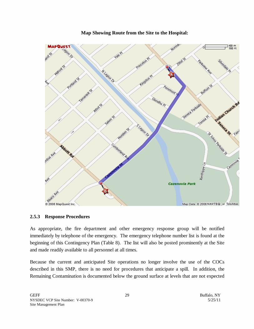
GEFF 29 Buffalo, NYNYSDEC VCP Site Number: V-00370-9 5/25/11Site Management Plan
Map Showing Route from the Site to the Hospital:
2.5.3 Response Procedures
As appropriate, the fire department and other emergency response group will be notified
immediately by telephone of the emergency. The emergency telephone number list is found at the
beginning of this Contingency Plan (Table 8). The list will also be posted prominently at the Site
and made readily available to all personnel at all times.
Because the current and anticipated Site operations no longer involve the use of the COCs
described in this SMP, there is no need for procedures that anticipate a spill. In addition, the
Remaining Contamination is documented below the ground surface at levels that are not expected

GEFF 30 Buffalo, NYNYSDEC VCP Site Number: V-00370-9 5/25/11Site Management Plan
to require an evacuation plan. However, if future findings identify contamination that requires
such response procedures, the Volunteer or the owner of the property at that time shall submit to
NYSDEC and NYSDOH an amendment to this SMP that summarizes the findings and
appropriate modifications to this SMP to address the associated risks. All operations on the Site
will cease until this amendment is approved by NYSDEC and NYSDOH.

GEFF 31 Buffalo, NYNYSDEC VCP Site Number: V-00370-9 5/25/11Site Management Plan
3.0 SITE MONITORING PLAN
3.1 INTRODUCTION
3.1.1 General
The Monitoring Plan describes the measures for evaluating the performance and effectiveness of
the remedy to reduce or mitigate contamination at the Site. This Monitoring Plan may only be
revised with the approval of NYSDEC.
3.1.2 Purpose and Schedule
This Monitoring Plan describes the methods to be used for:
Evaluating Site information periodically to confirm that the ICs and ECs continue to beeffective in protecting public health and the environment;
Assessing achievement of the remedial performance criteria through groundwater progressmonitoring and confirmatory sampling;
Sampling and analysis of indoor air and soil vapors associated with the current or futurebuildings;
Assessing compliance with applicable NYSDEC standards, criteria and guidance,particularly ambient groundwater standards and Part 375 SCOs for soil; and
Preparing the necessary reports for the various monitoring activities.
To adequately address these issues, this Monitoring Plan provides information on:
Sampling locations, protocol, and frequency;
Information on all designed monitoring systems (e.g., well logs);
Analytical sampling program requirements;
Reporting requirements (including electronic data deliverable [EDD] requirements);
Quality Assurance/Quality Control (QA/QC) requirements;
Inspection and maintenance requirements for monitoring wells;
Monitoring well decommissioning procedures; and
Annual inspection and periodic certification.
Inspection of the soil cover system shall be conducted annually and after excavation activities
have been conducted. Semi-annual monitoring of the performance of the groundwater remedy
will be conducted until the reported total CVOC concentration in all wells achieve the SCG of 1
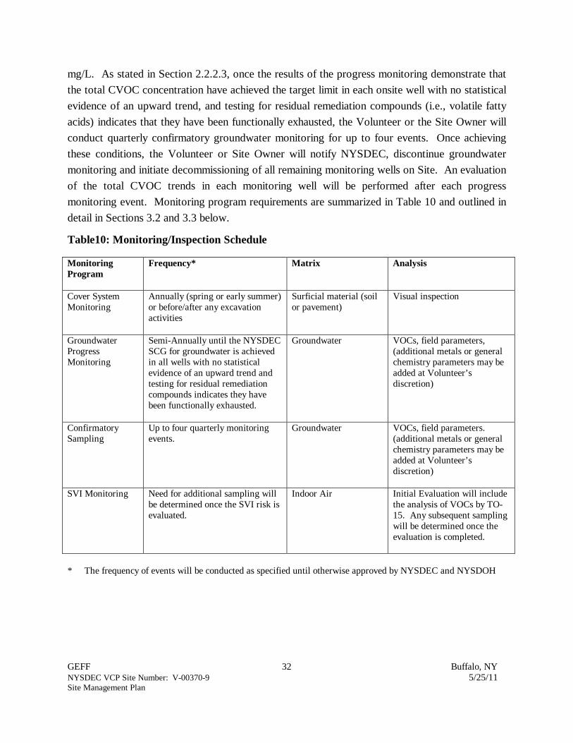
GEFF 32 Buffalo, NYNYSDEC VCP Site Number: V-00370-9 5/25/11Site Management Plan
mg/L. As stated in Section 2.2.2.3, once the results of the progress monitoring demonstrate that
the total CVOC concentration have achieved the target limit in each onsite well with no statistical
evidence of an upward trend, and testing for residual remediation compounds (i.e., volatile fatty
acids) indicates that they have been functionally exhausted, the Volunteer or the Site Owner will
conduct quarterly confirmatory groundwater monitoring for up to four events. Once achieving
these conditions, the Volunteer or Site Owner will notify NYSDEC, discontinue groundwater
monitoring and initiate decommissioning of all remaining monitoring wells on Site. An evaluation
of the total CVOC trends in each monitoring well will be performed after each progress
monitoring event. Monitoring program requirements are summarized in Table 10 and outlined in
detail in Sections 3.2 and 3.3 below.
Table10: Monitoring/Inspection Schedule
MonitoringProgram
Frequency* Matrix Analysis
Cover SystemMonitoring
Annually (spring or early summer)or before/after any excavationactivities
Surficial material (soilor pavement)
Visual inspection
GroundwaterProgressMonitoring
Semi-Annually until the NYSDECSCG for groundwater is achievedin all wells with no statisticalevidence of an upward trend andtesting for residual remediationcompounds indicates they havebeen functionally exhausted.
Groundwater VOCs, field parameters,(additional metals or generalchemistry parameters may beadded at Volunteer’sdiscretion)
ConfirmatorySampling
Up to four quarterly monitoringevents.
Groundwater VOCs, field parameters.(additional metals or generalchemistry parameters may beadded at Volunteer’sdiscretion)
SVI Monitoring Need for additional sampling willbe determined once the SVI risk isevaluated.
Indoor Air Initial Evaluation will includethe analysis of VOCs by TO-15. Any subsequent samplingwill be determined once theevaluation is completed.
* The frequency of events will be conducted as specified until otherwise approved by NYSDEC and NYSDOH

GEFF 33 Buffalo, NYNYSDEC VCP Site Number: V-00370-9 5/25/11Site Management Plan
3.2 SOIL COVER SYSTEM MONITORING
As discussed in Section 2.2.2.1, the soil cover system is a permanent, passive control that includes
clean soil cover/cap in landscaped areas, asphalt covered/paved parking and throughways, and
concrete covered sidewalks that is integrated into the current use of the property. The current
cover system is expected to remain in place in perpetuity with routine maintenance (i.e.,
landscaping maintenance, asphalt pavement sealing and repair, municipal inspection of sidewalks
and associated repair) expected with Site use.
The cover system monitoring will be conducted annually in the spring or early summer season and
will involve a visual walk-over inspection of the Site. Additional inspections will be required after
any redevelopment of the property that involves removal and replacement of any section of the
pavement, including excavations. Unscheduled inspections may take place when a suspected
failure in the cover system has been reported or an emergency occurs that is deemed likely to
affect the operation of the system.
The visual inspection will involve an evaluation of the integrity of the following features on Site:
The sidewalk along Kingston Place and Seneca Street;
The landscaped area between the northwestern edge of the parking lot and the sidewalkalong Kingston Place;
The asphalt pavement parking lot surrounding the current building;
The landscaped area in front (northeast) of the current building.
A complete list of components to be checked is provided in the Inspection Checklist, presented in
Appendix E. For landscaped areas, observations including areas of deterioration, water erosion,
subsidence, or ponding will be documented on the inspection form and evaluated. For paved
areas (i.e., asphalt, sidewalk), separation cracks or vertical off-sets that are greater than one-inch
shall be documented and sealed or repaired.
3.3 MEDIA MONITORING PROGRAM
SMP activities include monitoring of groundwater remediation progress and contingency
monitoring of SVI potential depending on Site use and redevelopment. As discussed above,
groundwater monitoring includes limited progress monitoring following confirmatory sampling,
followed by well decommissioning activities. The contingency SVI monitoring will involve an
initial evaluation prior to re-occupation of the current building and/or prior to the design and

GEFF 34 Buffalo, NYNYSDEC VCP Site Number: V-00370-9 5/25/11Site Management Plan
construction of new occupied buildings. This evaluation will identify the SVI risk present for
building occupation and outline a program necessary for monitoring and/or mitigating the risk, if
present. Detailed discussions of the monitoring programs are provided below.
3.3.1 Groundwater Progress Monitoring and Confirmatory Sampling
Groundwater progress monitoring and confirmatory sampling will be conducted to assess the
performance of the remedy as the groundwater concentrations approach the remedial goal of 1
part-per-million (ppm) in each of the on-site monitoring wells serving as the monitoring program
wells.
This objective is based on the remedies implemented and ICs put in place by the Volunteer. As
discussed in Sections 1.3.1, the current and planned land-use of the Site and neighboring
properties limits potential exposure routes for the impacted perched groundwater zones. Near-
surface soil that was identified as impacted and a potential source of groundwater contamination
was excavated and disposed off Site in 2003. In as much as there are no active potable water
supply wells on Site or off Site that are withdrawing groundwater from the impacted groundwater
zone, there is no significant risk posed to public health due to the detection of part-per-billion
(ppb) concentrations of CVOCs in groundwater in the vicinity of the Site. In addition, there
appears to be no significant future risk to human health given the unlikely potential for future
potable use of the shallow aquifer underlying the Site.
To confirm that groundwater has achieved the objectives stated above, a network of monitoring
wells has been established that includes upgradient well MW-2, downgradient wells MW-4, MW-
13, MW-11, and PZ-A, and deep well MW-4A, as illustrated on Figure 15. The network of on-
site wells was selected based on the historic groundwater concentrations on Site (Figure 11) and
is intended to reflect CVOC concentrations in the source area relative to the SCGs. Monitoring
well MW-2 is also included to confirm upgradient to cross-gradient concentrations. The
configuration of the monitored zone is illustrated in cross-section A-A’ (Figure 4). Monitoring
well construction logs for the wells included in the network are included in
Appendix F.
As stated above, groundwater progress monitoring will be conducted on a semi-annual basis until
the reported total CVOC concentration in each of the selected wells achieves the NYSDEC
defined SCG of 1 mg/L with no statistical evidence of an upward trend and residual remediation
compounds previously injected (i.e., volatile fatty acids) have been functionally exhausted. The
Volunteer will then conduct up to four quarterly confirmatory groundwater monitoring events

GEFF 35 Buffalo, NYNYSDEC VCP Site Number: V-00370-9 5/25/11Site Management Plan
using the selected wells and upon achieving these conditions, groundwater monitoring activities
shall cease and a request will be submitted to NYSDEC for permission to decommission the
remaining wells.
The sampling frequency may be modified with the approval of NYSDEC. The SMP will be
modified to reflect changes in sampling plans approved by NYSDEC.
Deliverables for the groundwater monitoring program (including EDD files) are specified below.
3.3.1.1 Sampling Protocol
All monitoring well sampling activities will be recorded in a field book and a groundwater-
sampling log (example form presented in Appendix G). Other observations (e.g., well integrity,
etc.) will be noted on the well sampling log. The well sampling log will serve as the inspection
form for the groundwater monitoring well network.
Groundwater level measurements will be collected from all available wells prior to sampling.
Each of the wells selected to be sampled will be purged using low-flow pumping techniques while
monitoring temperature, specific conductance, pH, and ORP for stability. Groundwater samples
will be collected after the field parameters have stabilized or when three well volumes have been
removed. Sampled groundwater will be collected in laboratory-supplied bottles, placed in a
cooler, chilled to approximately 4 degrees Celsius (C), and transported to the analytical
laboratory by field crew or courier under chain-of-custody procedures.
Groundwater samples will be tested for VOCs by SW-846 Method 8260. At the Volunteer’s
discretion, samples may also be collected and tested for additional indicator parameters, including:
chloride (Environmental Protection Agency [EPA] Method 300), sulfate (EPA Method 300),
alkalinity (Standard Methods [SM] 2320B), nitrate/nitrite (EPA Method 353.2), and sodium,
calcium, manganese, and both dissolved and total iron using SW-846 Method 6010/6020.
To monitor QA/QC for each groundwater sampling event, one duplicate sample and one trip
blank will be collected during every monitoring event.
All purged water will be containerized within 55-gallon drums and stored on Site. A composite
sample of the contents of the drum(s) will be tested to evaluate whether the waste is characterized
as non-hazardous or hazardous for disposal purposes. As of December 2010, the criteria for
evaluating the composite sample results to determine whether the waste is hazardous or non-
hazardous is outlined in the New York State regulations in 6 NYCRR Part 371.3(e) and the
Federal Regulations in 40 Code of Federal Regulations (CFR) Part 261.24. Historic waste

GEFF 36 Buffalo, NYNYSDEC VCP Site Number: V-00370-9 5/25/11Site Management Plan
characterization evaluations have found that the constituents most likely to impact the evaluation
are the VOC constituents listed in Table 11 below (their respective criteria for determining the
hazardous character of the waste is also included).
Table 11: Hazardous Waste Evaluation Criteria for Waste Water (As of December 2010)
Constituent 6 NYCRR Part 371.3 (e)(as of December 2010)
40 CFR Part 261.24(as of December 2010)
PCE 0.7 mg/L 0.7 mg/L
TCE 0.5 mg/L 0.5 mg/L
Vinyl Chloride 0.2 mg/L 0.2 mg/L
3.3.1.2 Monitoring Well Repairs, Replacement and Decommissioning
This section outlines the procedures for repairing or replacing selected wells as needed and the
planned decommissioning of wells remaining on Site and off Site that are not selected for
groundwater progress monitoring or confirmatory sampling.
If any wells are identified as unusable, either through biofouling or silt accumulation, the wells will
be physically agitated/surged and redeveloped. Additionally, if an event renders any monitoring
wells as unusable, the use of the well in question will be evaluated to determine whether removal
or replacement is most appropriate. Wells that are to be removed from the monitoring program
shall be properly decommissioned (as per the Monitoring Plan).
Repairs and/or replacement of wells that are deemed necessary for continued progress or
confirmatory monitoring will be performed based on assessments of structural integrity and
overall performance.
The NYSDEC will be notified prior to any repair or decommissioning of monitoring wells for the
purpose of replacement, and the repair or decommissioning and replacement process will be
documented in the subsequent periodic report. Well decommissioning without replacement will be
done only with the prior approval of NYSDEC. Well abandonment will be performed in
accordance with NYSDEC’s “Groundwater Monitoring Well Decommissioning Procedures.”
Monitoring wells that are decommissioned because they have been rendered unusable will be
reinstalled in the nearest available location, unless otherwise approved by the NYSDEC.

GEFF 37 Buffalo, NYNYSDEC VCP Site Number: V-00370-9 5/25/11Site Management Plan
The remaining shallow and deep wells that were installed by the Volunteer for the on-site and off-
site exposure assessment (conducted between 2002 and 2006) continue to pose a risk as a
potential conduit to the shallow and deep groundwater zones in the region. Accordingly, the
Volunteer proposes to decommission these wells along with the on Site wells not included on the
selected list of wells to be monitored during the progress monitoring and confirmatory sampling.
Abandonment/decommissioning of the remaining wells (i.e. those not included in the progress or
confirmatory monitoring programs) will be done once this SMP is approved by NYSDEC. Well
abandonment will be performed in accordance with NYSDEC’s “Groundwater Monitoring Well
Decommissioning Procedures.”
3.3.2 Soil Vapor Intrusion (SVI) Monitoring
The Site is currently unoccupied and there are no defined plans for whether re-occupation will
involve the current building or the design, construction, and occupation of a new building.
Accordingly, no SVI monitoring is necessary at this time, nor is any currently planned on Site.
Once development plans for the Site have been established, an SVI investigation and evaluation of
the results will be conducted in accordance with Sections 2 and 3 of the NYSDOH Final SVI
Guidance. The NYSDEC and NYSDOH shall be notified prior to conducting the SVI
investigation.
If the current building will be re-occupied, indoor air and/or sub-slab soil vapor samples will likely
be collected in accordance with the protocols outlined in Sections 2.4 through 2.9 of the
NYSDOH Final SVI Guidance. The samples will preferably be collected during the heating
season while the Heating, Ventilation, and Air Conditioning (HVAC) system is operating;
however, the scheduling of the sampling will depend on when the new occupant needs to take
possession. The samples are commonly collected over a 24-hour period in evacuated stainless
steel SUMMA canisters equipped with flow regulators. Soil vapor and air samples will be
analyzed, by a NYSDOH certified laboratory, for VOCs in accordance with EPA Method TO-15.
Prior to sampling, a NYSDOH Indoor Air Quality Questionnaire and Building Inventory will be
completed in accordance with Section 2.11 of the NYSDOH Final SVI Guidance to evaluate
potential presence of confounding sources that may interfere with evaluation of the analytical
results.
The investigation sampling schedule will be coordinated with NYSDEC and NYSDOH in order to
adequately evaluate the SVI risk potential for the planned occupied building on Site.

GEFF 38 Buffalo, NYNYSDEC VCP Site Number: V-00370-9 5/25/11Site Management Plan
3.4 SITE-WIDE INSPECTION
Site-wide inspections will be performed on an annual basis and will include the soil cover system
and SSD system inspections, if any. Site-wide inspections that include the soil cover system and
SSD system (as appropriate) will also be performed after all severe weather conditions that may
affect ECs or monitoring devices. During these inspections, the appropriate inspection form will
be completed (Appendix E). The form will compile sufficient information to assess the following:
Compliance with all ICs, including Site usage;
An evaluation of the condition and continued effectiveness of ECs, to the extent present;
General Site conditions at the time of the inspection;
The Site management activities being conducted including, where appropriate,confirmation sampling and a health and safety inspection;
Compliance with permits and schedules included in the O&M Plan (if applicable); and
Confirm that Site records (if operating) and those kept at the Region 9 NYSDEC office inBuffalo, New York are up to date.
3.5 MONITORING QUALITY ASSURANCE/QUALITY CONTROL (QA/QC)
All sampling and analyses will be performed in accordance with the requirements of the Quality
Assurance Project Plan (QAPP) prepared for the Site (Appendix H). Main Components of the
QAPP include:
QA/QC Objectives for Data Measurement;
Sampling Program: Sample containers will be provided by the laboratory to certify that they are properly
washed, decontaminated, and dosed with appropriate preservative (if applicable) priorto sample collection and analysis. Containers with preservative will be properlylabeled as such.
Sample holding times will be in accordance with the NYSDEC Analytical ServicesProtocol (ASP) requirements.
Field QC samples (e.g., trip blanks and coded field duplicates) will be collected asnecessary.
Sample Tracking and Custody;
Calibration Procedures: All field analytical equipment will be calibrated immediately prior to each day's use.
Calibration procedures will conform to manufacturer's standard instructions.
GEFF 39 Buffalo, NYNYSDEC VCP Site Number: V-00370-9 5/25/11Site Management Plan
The laboratory will follow all calibration procedures and schedules as specified in EPASW-846 and subsequent updates that apply to the instruments used for the analyticalmethods.
Analytical Procedures;
Preparation of a Data Usability Summary Report (DUSR), which will present the resultsof data validation, including a summary assessment of laboratory data packages, samplepreservation and chain-of-custody procedures, and a summary assessment of precision,accuracy, representativeness, comparability, and completeness for each analytical method.
Internal QC and Checks;
QA Performance and System Audits;
Preventative Maintenance Procedures and Schedules;
Corrective Action Measures.
3.6 MONITORING REPORTING REQUIREMENTS
All documentation, including field forms and any other information or data generated during
regular monitoring events and inspections will be kept on file on Site, if operating. In addition,
copies of all documentation will also be kept at the Region 9 NYSDEC office located at 270
Michigan Avenue in Buffalo, New York 14203. All forms, and other relevant reporting formats
used during the monitoring/inspection events, will be (1) subject to approval by NYSDEC and (2)
submitted at the time of the Periodic Review Report, as specified in the Reporting Plan of this
SMP.
All monitoring results will be reported to NYSDEC on a periodic basis in the Periodic Review
Report. A letter report will be prepared summarizing each groundwater monitoring event. The
letter report will include, at a minimum:
Date of event;
Personnel conducting sampling;
Description of the activities performed;
Type of samples collected (e.g., groundwater, sub-slab vapor, indoor air, outdoor air,etc.);

GEFF 40 Buffalo, NYNYSDEC VCP Site Number: V-00370-9 5/25/11Site Management Plan
Copies of all field forms completed (e.g., well sampling logs, chain-of-custodydocumentation, etc.);
Sampling results in comparison to appropriate standards/criteria;
A figure illustrating sample type and sampling locations;
Copies of all laboratory data sheets and the required laboratory data deliverables requiredfor all points sampled (o be submitted electronically in the NYSDEC-identified format);
An EDD file of the monitoring event data meeting the format requirements of the currentNYSDEC guidance (as of January 2011, EDD files shall follow the format specified in theEnvironmental Information Management System [EIMS], as set forth on the DECwebsite: http://www.dec.ny.gov/chemical/62440.html);
Any observations, conclusions, or recommendations; and
A determination as to whether groundwater conditions have changed since the lastreporting event.
Data will be reported in hard copy or digital format as determined by NYSDEC. A summary of
the monitoring program deliverables are summarized in Table 12 below.
Table 12: Schedule of Monitoring/Inspection Reports
Task Reporting Frequency*
Site-wide Inspection Report Annually
Soil Cover System Monitoring Annually, concurrent with the Site-wide InspectionReport
SVI-related Monitoring Will be determined once an evaluation for futureoccupation of any building on Site has been conducted
Groundwater Progress Monitoring Semi-annual until the NYSDEC SCG for groundwateris achieved in all wells with no statistical evidence of anupward trend and testing for residual remediationcompounds indicates they have been functionallyexhausted.
Confirmatory Sampling After NYSDEC SCG for groundwater is achieved in allwells, Confirmatory Sampling will be performed andreported Quarterly until four consecutive monitoringevents confirm that the groundwater on Site is withinthe NYSDEC SCGs
* The frequency of events will be conducted as specified until otherwise approved by NYSDEC

GEFF 41 Buffalo, NYNYSDEC VCP Site Number: V-00370-9 5/25/11Site Management Plan
4.0 OPERATION AND MAINTENANCE (O&M) PLAN
4.1 INTRODUCTION
The site remedy currently does not rely on any active ECs (mechanical systems), such as SSD
systems or air sparge/ soil vapor extraction (SVE) systems to protect public health and the
environment. Therefore, the O&M of such components is not included in this SMP.
Prior to the re-occupation of the current building or the design and construction of a new
occupied building, a SVI investigation will be conducted in accordance with the NYSDOH Final
SVI Guidance to evaluate whether a SVI risk potential exists that requires additional monitoring
and/or mitigation.
If the results of the evaluation indicate the need for an active EC (i.e., SSD system), an O&M
Plan will be submitted to NYSDEC and/or NYSDOH as a proposed amendment to this SMP.
Any such O&M Plan would include:
Steps necessary to allow individuals unfamiliar with the Site to operate and maintain thesystem;
An O&M contingency plan; and,
A schedule for periodic review and updating of the O&M Plan to reflect changes in Siteconditions or the manner in which the system is operated and maintained.
Appropriate reporting requirements to ensure that the system is properly operating andmaintained.
GEFF 42 Buffalo, NYNYSDEC VCP Site Number: V-00370-9 5/25/11Site Management Plan
5.0 INSPECTIONS, REPORTING, AND CERTIFICATIONS
5.1 SITE INSPECTIONS
5.1.1 Inspection Frequency
All inspections will be conducted at the frequency specified in the schedules provided in Section 3
Monitoring Plan of this SMP. At a minimum, a Site-wide inspection will be conducted annually.
Inspections of remedial components will also be conducted when a breakdown of any treatment
system component (if installed at a later date) has occurred or whenever a severe condition has
taken place, such as an erosion or flooding event that may affect the passive ECs.
5.1.2 Inspection Forms, Sampling Data, and Maintenance Reports
All inspections and monitoring events will be recorded on the appropriate forms for their
respective system which are contained in Appendix E with the general site-wide inspection form
that will be completed during the site-wide inspection. These forms are subject to NYSDEC
revision.
All applicable inspection forms and other records, including all media sampling data and system
inspection reports, generated for the Site during the reporting period will be provided in electronic
format in the Periodic Review Report
5.1.3 Evaluation of Records and Reporting
The results of the inspection and Site monitoring data will be evaluated as part of the EC/IC
certification to confirm that the:
EC/ICs are in place, are performing properly, and remain effective;
The Monitoring Plan is being implemented;
If applicable, operation and maintenance activities are being conducted properly; and,based on the above items,
The Site remedy continues to be protective of public health and the environment and isperforming as designed in the RA Report dated July 2005 and the RAS Report dated June2007.
GEFF 43 Buffalo, NYNYSDEC VCP Site Number: V-00370-9 5/25/11Site Management Plan
5.2 CERTIFICATION, OF EC/ICS
After the last inspection of the reporting period, a qualified environmental professional or
Professional Engineer licensed to practice in New York State will prepare the following
certification:
For each IC or EC identified for the Site, I certify that all of the following statements are true:
The inspection of the Site to confirm the effectiveness of the ICs/ECs required by theremedial program was performed under my direction;
The IC and/or EC employed at this Site is unchanged from the date the control was put inplace, or last approved by the Department;
Nothing has occurred that would impair the ability of the control to protect the publichealth and environment;
Nothing has occurred that would constitute a violation or failure to comply with anySMP for this control;
Access to the Site will continue to be provided to the Department to evaluate thecontinued maintenance of this control;
Use of the Site is compliant with the Declaration dated July 20;
Any active engineering control systems installed on Site are performing as designed andare effective;
To the best of my knowledge and belief, the work and conclusions described in thiscertification are in accordance with the requirements of the Site remedial program and/orgenerally accepted engineering practices; and
The information presented in this report is accurate and complete.
I certify that all information and statements in this certification form are true. Iunderstand that a false statement made herein is punishable as a Class “A” misdemeanor,pursuant to Section 210.45 of the Penal Law. I, [name], of [business address], amcertifying as [Owner or Owner’s Designated Site Representative] (and if the Site consistsof multiple properties): [I have been authorized and designated by all Site owners to signthis certification] for the Site.
The signed certification will be included in the Periodic Review Report described below.

GEFF 44 Buffalo, NYNYSDEC VCP Site Number: V-00370-9 5/25/11Site Management Plan
5.3 PERIODIC REVIEW REPORT
A Periodic Review Report will be submitted to the Department every year, beginning 18 months
after the Release and Covenant Not to Sue is issued. In the event that the Site is subdivided into
separate parcels with different ownership, a single Periodic Review Report will be prepared that
addresses the Site described in Appendix B (Metes and Bounds). The report will be prepared in
accordance with NYSDEC DER-10 and submitted within 45 days of the end of each certification
period. Media sampling results will also incorporated into the Periodic Review Report. The
report will include:
Identification, assessment and certification of all ECs/ICs required by the remedy for theSite;
Results of the required annual Site inspections and severe condition inspections, ifapplicable;
All applicable inspection forms and other records generated for the Site during thereporting period in electronic format;
A summary of any discharge monitoring data and/or information generated during thereporting period with comments and conclusions;
Data summary tables and graphical representations of contaminants of concern by media(groundwater, soil vapor), which include a listing of all compounds analyzed, along withthe applicable standards, with all exceedances highlighted. These will include apresentation of past data as part of an evaluation of contaminant concentration trends;
Results of all analyses, copies of all laboratory data sheets, and the required laboratorydata deliverables for all samples collected during the reporting period will be submittedelectronically in a NYSDEC-approved format;
An EDD file of the monitoring event data meeting the format requirements of the currentNYSDEC guidance (as of January 2011, EDD files shall follow the format specified in theEIMS, as set forth on the DEC website: http://www.dec.ny.gov/chemical/62440.html);
A Site evaluation, which includes the following:
Compliance with the requirements of the soil remedy outlined in the Site-specific RAReport dated July 2005 and groundwater remedy outlined in the Site-specific RASReport dated June 2007;
Any new conclusions or observations regarding Site contamination based oninspections or data generated by the Monitoring Plan for the media being monitored;

GEFF 45 Buffalo, NYNYSDEC VCP Site Number: V-00370-9 5/25/11Site Management Plan
Recommendations regarding any necessary changes to the remedy and/or MonitoringPlan; and
The overall performance and effectiveness of the remedy.
The Periodic Review Report will be submitted, in hard-copy format, to the NYSDEC Central
Office and Regional Office in which the Site is located, and in electronic format to NYSDEC
Central Office, Regional Office, and the NYSDOH Bureau of Environmental Exposure
Investigation.
5.4 CORRECTIVE MEASURES PLAN
If any component of the remedy is found to have failed, or if the periodic certification cannot be
provided due to the failure of an IC/EC, a corrective measures plan will be submitted to the
NYSDEC for approval. This plan will explain the failure and provide the details and schedule for
performing work necessary to correct the failure. Unless an emergency condition exists, no work
will be performed pursuant to the corrective measures plan until it is approved by the NYSDEC.

1/6/06 6/7/06 3/20/2007* 12/5/2007* 7/1/2008* 3/18/2009* 6/24/09 2/11/10 6/23/10
Top of Groundwater Groundwater Groundwater Groundwater Groundwater Groundwater Groundwater Groundwater Groundwater Groundwater Groundwater
Casing Elevation Elevation Elevation Elevation Elevation Elevation Elevation Elevation Elevation Elevation Elevation
Well No. (feet) (feet) (feet) (feet) (feet) (feet) (feet) (feet) (feet) (feet) (feet) (feet)
Shallow Wells
MW-1 591.56 583.64 582.00 583.70 583.03 583.19 NM 583.33 583.37 582.35 NM 582.67
MW-2 590.24 583.41 581.82 583.30 581.79 582.91 582.82 583.25 583.26 582.30 581.93 582.53
MW-3 589.73 583.30 581.73 583.34 581.73 582.89 NM 583.01 583.02 582.10 NM 582.43
MW-4 589.47 583.26 581.72 583.14 581.67 582.83 582.78 583.15 583.12 582.13 581.92 582.47
MW-5 590.25 NM 581.85 NM 581.80 582.99 NM 583.16 NM 582.39 NM 582.49
MW-6 590.95 583.93 581.99 583.61 582.00 583.11 582.73 583.26 583.26 582.37 582.05 582.72
MW-7 589.52 582.91 581.50 582.59 581.58 582.42 582.11 582.54 581.54 581.80 581.66 582.15
MW-8 588.22 583.15 581.41 582.93 581.33 582.49 NM 582.55 582.63 581.64 NM 582.05
MW-9 588.81 583.16 581.79 582.89 581.62 582.52 582.37 582.72 582.68 581.88 NM 582.32
MW-10 588.29 583.39 581.38 583.30 581.40 NM NM 578.95 578.91 582.67 NM NM
MW-11 589.48 583.07 581.60 582.89 581.58 582.60 582.72 583.09 582.95 582.06 581.82 582.43
MW-12 589.06 580.12 581.06 582.00 581.06 581.98 NM 581.95 582.07 581.34 581.32 581.73
MW-13 589.77 583.37 581.72 583.25 581.68 582.85 582.76 583.23 582.52 582.08 581.86 582.45
MW-14 588.66 583.31 581.66 583.67 581.63 582.87 NM 582.82 582.95 581.94 NM 582.39
MW-15 589.23 582.72 581.34 582.51 578.51 582.34 NM 582.35 582.41 581.61 581.5 582.10
PZ-A 589.86 NA NA NA 581.66 582.81 582.49 582.01 582.78 581.85 581.55 582.38
PZ-1 588.74 583.49 581.84 583.34 581.72 582.92 NM 582.97 582.96 581.98 NM 582.41
PZ-2 589.18 583.17 581.62 582.84 581.59 582.95 NM 582.69 582.75 581.70 NM NM
PZ-3 588.42 NM NM 582.79 582.85 581.79 NM 582.22
Deep Wells
MW-4A 589.04 579.35 578.42 578.55 578.74 579.28 578.96 578.98 579.30 578.62 578.89 578.90
MW-11A 589.31 580.06 579.12 579.37 579.29 580.10 579.52 579.54 579.97 579.16 579.41 579.52
Reference elevations measured on August 11, 2009 by URS Corporation.
NM = Not measured
* = Groundwater elevations reported for this monitoring event may have been presented in previous reports with different values because
the previously reported values were based on previous "top of casing" reference values that are used in this table.
BUFFALO, NEW YORK
1/10/05 5/25/05
TABLE 1
GROUNDWATER ELEVATIONS
GE FRANCHISE FINANCE - PARCEL 2
2139 SENECA STREET
NYSDEC VCA V-00370-9
GE Capital Franchise Finance
14964473
Parcel 2 - Seneca St.
Buffalo, NY
5/25/11

TAGM Unrestricted PPH SB-1B SB-3 SB-4 SB-5* SB-6* SB-7* SB-8* SB-9* SB-10*
Volatile Organic Compounds Std Use Commercial (8.0-12.0) (12.0-16.0) (12.0-16.0) (12.0-16.0) (8.0-12.0) (8.0-12.0) (4.0-8.0) (0-4.0) (8.0-12.0)
(mg/kg; SW-846 8260) (Track 1) 7/21/99 7/21/99 7/21/99 7/21/99 7/21/99 7/21/99 7/21/99 7/21/99 7/21/99
Acetone 0.2 0.05 500b
<0.1 <0.1 0.025 - - - - - -
Tetrachloroethene 1.4 1.3 150 0.015 12 0.421 - - - - - -
Trichloroethene 0.7 0.47 200 0.002 0.054 0.012 - - - - - -
Semivolatile Organic Compounds
(mg/kg; SW-846 8270)
Benzo(a)anthracene 0.224 1c
5.6 - - - - 0.089 <0.33 0.45 6.34 <0.33
Benzo(a)pyrene 0.061 1c
1f
- - - - 0.087 <0.33 0.52 6.08 <0.33
Benzo(b)fluoranthene 1.1 1c
5.6 - - - - 0.157 <0.33 0.513 6.28 <0.33
Benzo(k)fluoranthene 1.1 0.8c
56 - - - - 0.087 <0.33 0.475 4.08 <0.33
Chrysene 0.4 1c
56 - - - - 0.129 <0.33 0.514 6.67 <0.33
Dibenz(a,h)anthracene 0.014 0.1 0.56 - - - - <0.33 <0.33 <0.33 1.69 <0.33
Metals (mg/kg)
Arsenic 7.5 16 16f
- - - - - - - - -
Barium 300 350 400 - - - - - - - - -
Cadmium 1 2.5 9.3 - - - - - - - - -
Chromium 10 30 1,500 - - - - - - - - -
Copper 25 50 270 - - - - - - - - -
Iron 2000 NS NS - - - - - - - - -
Mercury 0.1 0.3 2.8j
- - - - - - - - -
Nickel 13 30 310 - - - - - - - - -
Zinc 20 109 10,000d
- - - - - - - - -
TABLE 2
ANALYTICAL RESULTS SUMMARY
SOIL SAMPLING - PRE-REMEDIAL ACTIVITIES
1999-2006
SCOs Cleanup Objectives Sample ID (Depth, feet)
GE FRANCHISE FINANCE - PARCEL 2
2139 SENECA STREET
BUFFALO, NEW YORK
NYSDEC VCA V-00370-9
GE Capital Franchise Finance
14964473
Page 1 of 6
Parcel 2 - Seneca St.
Buffalo, NY
5/22/11

TAGM Unrestricted PPH SB-11 SB-12 SB-13 SB-14 SB-15 SB-16A
Volatile Organic Compounds Std Use Commercial (7-9) (7-9) (7-9) (5.0-7.0) (5.0-7.0) (7.0-9.0) (0-2.0) (2.0-4.0) (4.0-6.0) (6.0-8.0)
(mg/kg; SW-846 8260) (Track 1) 9/13/00 9/13/00 9/13/00 9/13/00 9/13/00 9/18/00 8/22/01 8/22/01 8/22/01 8/22/01
Acetone 0.2 0.05 500b
- - - <0.024 <0.021 0.42 J <0.021 <0.021 <0.025 <0.025
Tetrachloroethene 1.4 1.3 150 - - - 0.0083 0.028 7.2 0.013 0.033 0.016 0.14
Trichloroethene 0.7 0.47 200 - - - <0.006 <0.0053 <0.31 <0.0052 <0.0052 <0.0062 <0.0062
Semivolatile Organic Compounds
(mg/kg; SW-846 8270)
Benzo(a)anthracene 0.224 1c
5.6 <0.4 <0.41 <0.39 <0.4 0.710 J <0.41 - - - -
Benzo(a)pyrene 0.061 1c
1f
<0.4 <0.41 <0.39 <0.4 0.720 J <0.41 - - - -
Benzo(b)fluoranthene 1.1 1c
5.6 <0.4 <0.41 <0.39 <0.4 0.750 J <0.41 - - - -
Benzo(k)fluoranthene 1.1 0.8c
56 <0.4 <0.41 <0.39 <0.4 0.730 J <0.41 - - - -
Chrysene 0.4 1c
56 <0.4 <0.41 <0.39 <0.4 0.830 J 0.022 J - - - -
Dibenz(a,h)anthracene 0.014 0.1 0.56 <0.4 <0.41 <0.39 <0.4 1.8 U J <0.41 - - - -
Metals (mg/kg)
Arsenic 7.5 16 16f
9.7 12.9 8.6 9.3 4.8 9.9 - - - -
Barium 300 350 400 80.2 103 50.8 56.4 71.4 67.9 - - - -
Cadmium 1 2.5 9.3 0.61 U J 0.62 U J 0.60 U J 0.60 U J 0.48 J 0.63 U J - - - -
Chromium 10 30 1,500 18.9 18.6 13.2 12.9 22.8 13.7 - - - -
Copper 25 50 270 30.0 33.7 27.1 31.5 21.0 32.0 - - - -
Iron 2000 NS NS 34,000 36,100 26,300 26,900 9,270 28,000 - - - -
Mercury 0.1 0.3 2.8j
<0.032 <0.026 <0.017 <0.033 0.13 0.034 - - - -
Nickel 13 30 310 37.8 37.5 28.4 31.2 8.7 31.3 - - - -
Zinc 20 109 10,000d
102 103 81.0 84.6 186 87.5 - - - -
TABLE 2 (Continued)
SCOs Cleanup Objectives
SB-17
Sample ID (Depth, feet)
NYSDEC VCA V-00370-9
GE Capital Franchise Finance
14964473
Page 2 of 6
Parcel 2 - Seneca St.
Buffalo, NY
5/22/11

TAGM Unrestricted PPH SB-18 SB-19 SB-21 SB-22 SB-23 SB-24 SB-25 SB-26 SB-27 SB-28 SB-29
Volatile Organic Compounds Std Use Commercial (6.0-8.0) (6.0-8.0) (6.0-8.0) (11-12) (11.0-12.0) (8.0-10.0) (8.0-10.0) (10-12) (10-12) (6-8) (8-10)
(mg/kg; SW-846 8260) (Track 1) 8/22/10 8/20/01 8/20/01 8/22/01 8/22/01 8/20/01 8/20/01 8/20/01 8/20/01 8/20/01 8/20/01
Acetone 0.2 0.05 500b
<0.046 <0.025 <0.024 <0.024 <0.024 <0.024 <0.024 - - <0.025 <0.025
Tetrachloroethene 1.4 1.3 150 0.0029 J 29 0.0029 J 0.019 0.0016 J 0.053/0.0098 0.0015 J - - <0.0062 <0.0062
Trichloroethene 0.7 0.47 200 0.0061 0.025 <0.006 <0.0059 <0.0059 <0.006 <0.006 - - <0.0062 <0.0062
Semivolatile Organic Compounds
(mg/kg; SW-846 8270)
Benzo(a)anthracene 0.224 1c
5.6 3.2 J <0.41 - - - <0.04 - <0.039 <0.4 - -
Benzo(a)pyrene 0.061 1c
1f
2.2 J <0.41 - - - <0.04 - <0.039 <0.4 - -
Benzo(b)fluoranthene 1.1 1c
5.6 2 J <0.41 - - - <0.04 - <0.039 <0.4 - -
Benzo(k)fluoranthene 1.1 0.8c
56 1.4 J <0.41 - - - <0.04 - <0.039 <0.4 - -
Chrysene 0.4 1c
56 2.9 J <0.41 - - - <0.04 - <0.039 <0.4 - -
Dibenz(a,h)anthracene 0.014 0.1 0.56 <3.8 <0.41 - - - <0.04 - <0.039 <0.4 - -
Metals (mg/kg)
Arsenic 7.5 16 16f
- - - - - - - - - - -
Barium 300 350 400 - - - - - - - - - - -
Cadmium 1 2.5 9.3 - - - - - - - - - - -
Chromium 10 30 1,500 - - - - - - - - - - -
Copper 25 50 270 - - - - - - - - - - -
Iron 2000 NS NS - - - - - - - - - - -
Mercury 0.1 0.3 2.8j
- - - - - - - - - - -
Nickel 13 30 310 - - - - - - - - - - -
Zinc 20 109 10,000d
- - - - - - - - - - -
SCOs Cleanup Objectives Sample ID (Depth, feet)
TABLE 2 (Continued)
NYSDEC VCA V-00370-9
GE Capital Franchise Finance
14964473
Page 3 of 6
Parcel 2 - Seneca St.
Buffalo, NY
5/22/11
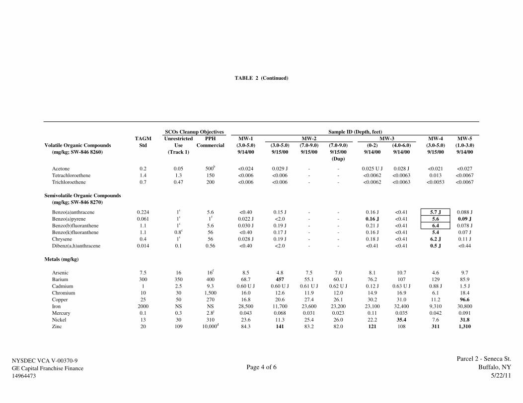
TAGM Unrestricted PPH MW-1 MW-4 MW-5
Volatile Organic Compounds Std Use Commercial (3.0-5.0) (3.0-5.0) (7.0-9.0) (7.0-9.0) (0-2) (4.0-6.0) (3.0-5.0) (1.0-3.0)
(mg/kg; SW-846 8260) (Track 1) 9/14/00 9/15/00 9/15/00 9/15/00 9/14/00 9/14/00 9/15/00 9/14/00
(Dup)
Acetone 0.2 0.05 500b
<0.024 0.029 J - - 0.025 U J 0.028 J <0.021 <0.027
Tetrachloroethene 1.4 1.3 150 <0.006 <0.006 - - <0.0062 <0.0063 0.013 <0.0067
Trichloroethene 0.7 0.47 200 <0.006 <0.006 - - <0.0062 <0.0063 <0.0053 <0.0067
Semivolatile Organic Compounds
(mg/kg; SW-846 8270)
Benzo(a)anthracene 0.224 1c
5.6 <0.40 0.15 J - - 0.16 J <0.41 5.7 J 0.088 J
Benzo(a)pyrene 0.061 1c
1f
0.022 J <2.0 - - 0.16 J <0.41 5.6 0.09 J
Benzo(b)fluoranthene 1.1 1c
5.6 0.030 J 0.19 J - - 0.21 J <0.41 6.4 0.078 J
Benzo(k)fluoranthene 1.1 0.8c
56 <0.40 0.17 J - - 0.16 J <0.41 5.4 0.07 J
Chrysene 0.4 1c
56 0.028 J 0.19 J - - 0.18 J <0.41 6.2 J 0.11 J
Dibenz(a,h)anthracene 0.014 0.1 0.56 <0.40 <2.0 - - <0.41 <0.41 0.5 J <0.44
Metals (mg/kg)
Arsenic 7.5 16 16f
8.5 4.8 7.5 7.0 8.1 10.7 4.6 9.7
Barium 300 350 400 68.7 457 55.1 60.1 76.2 107 129 85.9
Cadmium 1 2.5 9.3 0.60 U J 0.60 U J 0.61 U J 0.62 U J 0.12 J 0.63 U J 0.88 J 1.5 J
Chromium 10 30 1,500 16.0 12.6 11.9 12.0 14.9 16.9 6.1 18.4
Copper 25 50 270 16.8 20.6 27.4 26.1 30.2 31.0 11.2 96.6
Iron 2000 NS NS 28,500 11,700 23,600 23,200 23,100 32,400 9,310 30,800
Mercury 0.1 0.3 2.8j
0.043 0.068 0.031 0.023 0.11 0.035 0.042 0.091
Nickel 13 30 310 23.6 11.3 25.4 26.0 22.2 35.4 7.6 31.8
Zinc 20 109 10,000d
84.3 141 83.2 82.0 121 108 311 1,310
MW-3
Sample ID (Depth, feet)SCOs Cleanup Objectives
MW-2
TABLE 2 (Continued)
NYSDEC VCA V-00370-9
GE Capital Franchise Finance
14964473
Page 4 of 6
Parcel 2 - Seneca St.
Buffalo, NY
5/22/11

TAGM Unrestricted PPH
Volatile Organic Compounds Std Use Commercial (8-9) (10-11) (18-19) (7-8) (18-19) (26-27) (11-12) (27-28)
(mg/kg; SW-846 8260) (Track 1) 1/17/06 1/17/06 1/17/06 1/17/06 1/17/06 1/17/06 1/17/06 1/17/06
Acetone 0.2 0.05 500b
- - 0.041 - - - 0.026 J -
Tetrachloroethene 1.4 1.3 150 0.006 0.009 100 D 0.003 J 64 D 0.003 N J 0.003 N J 0.005
Trichloroethene 0.7 0.47 200 - - 2.0 D J - 2.4 D J - - -
Semivolatile Organic Compounds
(mg/kg; SW-846 8270)
Benzo(a)anthracene 0.224 1c
5.6 - - - - - - - -
Benzo(a)pyrene 0.061 1c
1f
- - - - - - - -
Benzo(b)fluoranthene 1.1 1c
5.6 - - - - - - - -
Benzo(k)fluoranthene 1.1 0.8c
56 - - - - - - - -
Chrysene 0.4 1c
56 - - - - - - - -
Dibenz(a,h)anthracene 0.014 0.1 0.56 - - - - - - - -
Metals (mg/kg)
Arsenic 7.5 16 16f
- - - - - - - -
Barium 300 350 400 - - - - - - - -
Cadmium 1 2.5 9.3 - - - - - - - -
Chromium 10 30 1,500 - - - - - - - -
Copper 25 50 270 - - - - - - - -
Iron 2000 NS NS - - - - - - - -
Mercury 0.1 0.3 2.8j
- - - - - - - -
Nickel 13 30 310 - - - - - - - -
Zinc 20 109 10,000d
- - - - - - - -
PZ-A TB-B TC-C
Sample ID (Depth, feet)SCOs Cleanup Objectives
TABLE 2 (Continued)
NYSDEC VCA V-00370-9
GE Capital Franchise Finance
14964473
Page 5 of 6
Parcel 2 - Seneca St.
Buffalo, NY
5/22/11

Soil samples collected by Conestoga Rovers & Associates between October 21 and November 3, 2003
TAGM Std. = New York State Recommended Soil Cleanup Objective, Technical and Administrative Guidance Memorandum (TAGM) #4046, January 24, 1994
PPH = Protection of Public Health
GW = Groundwater
ppm = Parts per million
mg/kg = Milligrams per kilogram
b = The Soil Cleanup Objectives (SCOs) for commercial use were capped at a maximum value of 500 ppm. See TSD Section 9.3
c = The SCOs for industrial use and the protection of groundwater were capped at a maximum value of 1,000 ppm. See Section 9.3
d = The SCOs for metals were capped at a maximum value of 10,000 ppm. See TSD Section 9.3
f = For constituents where the calculated SCO was lower than the rural soil background concentration as determined by the Department of Health rural soil survey,
the rural soil background concentration is used as the Track 2 SCO value for this use of the site
j = This SCO is the lower of the values for mercury (elemental) or mercury (inorganic salts). See TSD Table 5.6-1
* = VOC analyses for these samples were limited to BTEX (benzene, toluene, ethylbenzene, xylene) constituents
<0.1 = Analyte not detected at the reporting limit shown
D = Diluted sample
J = Estimated concentration
N,J = These concentrations are considered suspect based on the results of the Data Usability Summary Report (DUSR) provided by in the Current Status Report, dated October 11, 2006
U,J = Not detected at associated value, estimated
Values in Bold exceed TAGM Standards
6.34 = Values boxed and in bold exceed TAGM Standards and PPH Commercial Standards
Reference: Table C-1 in Appendix C of the Remediation Report
TABLE 2 (Continued)
NYSDEC VCA V-00370-9
GE Capital Franchise Finance
14964473
Page 6 of 6
Parcel 2 - Seneca St.
Buffalo, NY
5/22/11

Parameters (mg/L)
TCL Volatile Organics
Acetone - - 0.0029 J - - - - -
Benzene - - 0.0023 - - - - -
2-Butanone - - - - - - - -
1,1-Dichloroethene - - 0.0017 - - - - -
Cyclohexane - - - - - - - -
1,1-Dichloroethane - - - - - - 0.00069 J -
cis-1,2-Dichloroethene 0.027 - 0.540 D - - 0.011 - 0.016
trans-1,2-Dichloroethene - - 0.0042 - - - - -
Methyl-t-Butyl Ether (MTBE) - 0.0008 J - - - - - -
Methylcyclohexane - - - - - - - -
Tetrachloroethene 0.025 0.00088 J 12.0 D 0.00068 J - 0.045 - 0.390 D
Toluene - - - - - - - -
1,1,1-Trichloroethane - - - - - - 0.00058 J -
Trichloroethene 0.018 - 2.8 D - - 0.018 - 0.038
Vinyl Chloride - - 0.0082 - - - - -
Ethane, Ethene, and Methane
Ethane - - 0.015 NA NA NA NA -
Methane 0.017 - 0.036 NA NA NA NA 0.035
Cumulative CVOC Concentration 0.070 0.001 15.354 0.001 - 0.074 - 0.444
Samples collected on January 10 through 17, 2006 and were analyzed by Severn Trent Laboratory, Buffalo New York.
NM = Not Measured; NA = Not analyzed
J = Estimated concentration below reporting limit
D = Diluted sample
Note: CVOCs are the sum of PCE and its potential breakdown products (TCE, cis-1,2-DCE, trans-1,2-DCE, 1,1-DCE, 1,1-DCA, and vinyl chloride)
Shallow Alluvial
GE FRANCHISE FINANCE - PARCEL 2
2139 SENECA STREET
BUFFALO, NEW YORK
MW-4 MW-7 MW-8 MW-9 MW-10 MW-11
TABLE 3
ANALYTICAL RESULTS SUMMARY
GROUNDWATER SAMPLING - SUPPLEMENTARY INVESTIGATION
JANUARY 6-13, 2006 EVENT
MW-2 MW-3
NYSDEC VCA V-00370-9
GE Capital Franchise Finance
14964473
Page 1 of 8
Parcel 2 - Seneca St.
Buffalo, NY
5/25/11

Parameters (mg/L)
Metals
Calcium, total 50.4 85.7 246 NA NA NA NA 175
Iron, soluble 0.048 B 0.532 1.02 NA NA NA NA -
Iron, total 29.5 57.8 55.3 NA NA NA NA 3.590
Manganese, total 0.870 0.219 3.560 NA NA NA NA 1.030
Sodium, total 157 47.0 210 NA NA NA NA 217
General Chemistry
Chloride 396 64.1 376 NA NA NA NA 468
Nitrate-Nitrite - 7.7 - NA NA NA NA -
Sulfate 130 72.9 899 NA NA NA NA 606
Sulfide - - 0.20 NA NA NA NA -
Alkalinity, total 206 230 362 NA NA NA NA 247
Total Organic Carbon 1.1 1.3 4.0 NA NA NA NA 1.4
Field Parameters
Oxidation-Reduction Potential (mV) -50 39 -73 -28 -11 28 103 6
Specific Conductance (mS/cm) 2.18 1.35 3.42 3.62 2.66 1.49 1.19 2.23
pH (S.I.) 7.06 6.56 6.69 6.69 6.35 7.11 6.21 6.76
Temperature (Fahrenheit) 56.0 55.5 57.6 56.5 53.4 59.1 50.8 57.0
Turbidity 26 46.1 32.6 64 0 6.5 0 24.2
Dissolved Oxygen (mg/L) 0 0 0.2 0 0 4.31 0 0
Permanganate (mg/L) 0.8 NM 0.8 NM NM NM NM 0.2
Samples collected on January 10 through 17, 2006 and were analyzed by Severn Trent Laboratory, Buffalo New York.
NM = Not Measured; NA = Not analyzed
J = Estimated concentration below reporting limit
D = Diluted sample
Note: CVOCs are the sum of PCE and its potential breakdown products (TCE, cis-1,2-DCE, trans-1,2-DCE, 1,1-DCE, 1,1-DCA, and vinyl chloride)
MW-10 MW-11
TABLE 3 (Continued)
Shallow Alluvial (Continued)
MW-2 MW-3 MW-4 MW-7 MW-8 MW-9
NYSDEC VCA V-00370-9
GE Capital Franchise Finance
14964473
Page 2 of 8
Parcel 2 - Seneca St.
Buffalo, NY
5/25/11

Parameters
TCL Volatile Organics (mg/L)
Acetone - - - - 0.0038 J 0.0042 J - -
Benzene - - - - - - - -
2-Butanone - - - - - 0.0049 J - -
1,1-Dichloroethene 0.0036 - - 0.0017 0.0027 - - -
Cyclohexane - - - - - - - -
1,1-Dichloroethane - - - - - - - -
cis-1,2-Dichloroethene 1.7 D 0.017 0.00048 J 0.460 D 1.2 D 0.0079 0.016 0.016
trans-1,2-Dichloroethene - - - 0.0052 0.013 - - -
Methyl-t-Butyl Ether (MTBE) - - - - - - - -
Methylcyclohexane - - - - - - - -
Tetrachloroethene 5.8 D 0.470 D 0.00044 J 2.2 D 7.30 D 0.004 0.320 D 0.350 D
Toluene - - - - - - - -
1,1,1-Trichloroethane - - - - - - - -
Trichloroethene 2.4 D 0.039 - 0.520 D 2.1 D 0.0021 0.043 0.043
Vinyl Chloride 0.019 - - 0.0047 0.05 - - -
Ethane, Ethene, and Methane
Ethane - - - NA NA NA NA NA
Methane 0.029 - - NA NA NA NA NA
Cumulative CVOC Concentration 9.923 0.526 0.001 3.192 10.666 0.014 0.379 0.409
Samples collected on January 10 through 17, 2006 and were analyzed by Severn Trent Laboratory, Buffalo New York.
NM = Not Measured; NA = Not analyzed
J = Estimated concentration below reporting limit
D = Diluted sample
Note: CVOCs are the sum of PCE and its potential breakdown products (TCE, cis-1,2-DCE, trans-1,2-DCE, 1,1-DCE, 1,1-DCA, and vinyl chloride)
IW-15S Dup
(MW-100)MW-13 MW-14 MW-15 IW-2S IW-10 IW-15S
TABLE 3 (Continued)
Shallow Alluvial (Continued)
MW-12
NYSDEC VCA V-00370-9
GE Capital Franchise Finance
14964473
Page 3 of 8
Parcel 2 - Seneca St.
Buffalo, NY
5/25/11
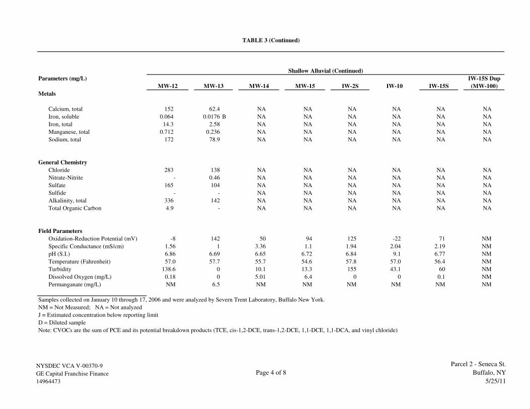
Parameters (mg/L)
Metals
Calcium, total 152 62.4 NA NA NA NA NA NA
Iron, soluble 0.064 0.0176 B NA NA NA NA NA NA
Iron, total 14.3 2.58 NA NA NA NA NA NA
Manganese, total 0.712 0.236 NA NA NA NA NA NA
Sodium, total 172 78.9 NA NA NA NA NA NA
General Chemistry
Chloride 283 138 NA NA NA NA NA NA
Nitrate-Nitrite - 0.46 NA NA NA NA NA NA
Sulfate 165 104 NA NA NA NA NA NA
Sulfide - - NA NA NA NA NA NA
Alkalinity, total 336 142 NA NA NA NA NA NA
Total Organic Carbon 4.9 - NA NA NA NA NA NA
Field Parameters
Oxidation-Reduction Potential (mV) -8 142 50 94 125 -22 71 NM
Specific Conductance (mS/cm) 1.56 1 3.36 1.1 1.94 2.04 2.19 NM
pH (S.I.) 6.86 6.69 6.65 6.72 6.84 9.1 6.77 NM
Temperature (Fahrenheit) 57.0 57.7 55.7 54.6 57.8 57.0 56.4 NM
Turbidity 138.6 0 10.1 13.3 155 43.1 60 NM
Dissolved Oxygen (mg/L) 0.18 0 5.01 6.4 0 0 0.1 NM
Permanganate (mg/L) NM 6.5 NM NM NM NM NM NM
Samples collected on January 10 through 17, 2006 and were analyzed by Severn Trent Laboratory, Buffalo New York.
NM = Not Measured; NA = Not analyzed
J = Estimated concentration below reporting limit
D = Diluted sample
Note: CVOCs are the sum of PCE and its potential breakdown products (TCE, cis-1,2-DCE, trans-1,2-DCE, 1,1-DCE, 1,1-DCA, and vinyl chloride)
(MW-100)
TABLE 3 (Continued)
Shallow Alluvial (Continued)
MW-12 MW-13 MW-14 MW-15 IW-2S IW-10 IW-15S
IW-15S Dup
NYSDEC VCA V-00370-9
GE Capital Franchise Finance
14964473
Page 4 of 8
Parcel 2 - Seneca St.
Buffalo, NY
5/25/11

Parameters
TCL Volatile Organics (mg/L)
Acetone - - - - - -
Benzene - - - - - -
2-Butanone - - - - - -
1,1-Dichloroethene - - - - - -
Cyclohexane - - - - - -
1,1-Dichloroethane - - - - - -
cis-1,2-Dichloroethene 0.015 - - - - 0.022
trans-1,2-Dichloroethene - - - - - -
Methyl-t-Butyl Ether (MTBE) - - - - - -
Methylcyclohexane - - - - - -
Tetrachloroethene 0.00051 J - - - - 0.0037
Toluene - - - - - 0.001
1,1,1-Trichloroethane - - - - - -
Trichloroethene 0.003 - - - - 0.0037
Vinyl Chloride 0.019 - - - - 0.0053
Ethane, Ethene, and Methane
Ethane - NA NA NA NA -
Methane 0.081 NA NA NA NA 0.009
Cumulative CVOC Concentration 0.038 - - - - 0.035
Samples collected on January 10 through 17, 2006 and were analyzed by Severn Trent Laboratory, Buffalo New York.
NM = Not Measured; NA = Not analyzed
J = Estimated concentration below reporting limit
D = Diluted sample
Note: CVOCs are the sum of PCE and its potential breakdown products (TCE, cis-1,2-DCE, trans-1,2-DCE, 1,1-DCE, 1,1-DCA, and vinyl chloride)
MW-11A
TABLE 3 (Continued)
Deep Aquifer
MW-4A MW-7A MW-8A MW-9A MW-10A
NYSDEC VCA V-00370-9
GE Capital Franchise Finance
14964473
Page 5 of 8
Parcel 2 - Seneca St.
Buffalo, NY
5/25/11

Parameters (mg/L)
Metals
Calcium, total 58.4 NA NA NA NA 140
Iron, soluble 0.348 NA NA NA NA -
Iron, total 137 NA NA NA NA 0.722
Manganese, total 0.991 NA NA NA NA 0.105
Sodium, total 67.8 NA NA NA NA 38.4
General Chemistry
Chloride 233 NA NA NA NA 142
Nitrate-Nitrite - NA NA NA NA 0.15
Sulfate 116 NA NA NA NA 108
Sulfide - NA NA NA NA -
Alkalinity, total 150 NA NA NA NA 236
Total Organic Carbon 5.7 NA NA NA NA 1.3
Field Parameters
Oxidation-Reduction Potential (mV) -187 42 18 44 -140 -26
Specific Conductance (mS/cm) 0.999 1.63 1.69 0.699 1.13 0.999
pH (S.I.) 8.84 7.52 7.32 8.89 7.41 7.48
Temperature (Fahrenheit) 56.3 57.8 52.4 54.7 52.7 55.8
Turbidity 34 25.9 >1000 19 149 <1,000
Dissolved Oxygen (mg/L) 0 1.36* 4.99* 0.63 0 4.65*
Permanganate (mg/L) 6.2 NM NM NM NM 2.1
Samples collected on January 10 through 17, 2006 and were analyzed by Severn Trent Laboratory, Buffalo New York.
NM = Not Measured; NA = Not analyzed
J = Estimated concentration below reporting limit
D = Diluted sample
Note: CVOCs are the sum of PCE and its potential breakdown products (TCE, cis-1,2-DCE, trans-1,2-DCE, 1,1-DCE, 1,1-DCA, and vinyl chloride)
* Dissolved oxygen measurement considered suspect due to inconsistent measurements
Deep Aquifer (Continued)
MW-4A MW-7A MW-8A
TABLE 3 (Continued)
MW-9A MW-10A MW-11A
NYSDEC VCA V-00370-9
GE Capital Franchise Finance
14964473
Page 6 of 8
Parcel 2 - Seneca St.
Buffalo, NY
5/25/11

Parameters
TCL Volatile Organics (mg/L)
Acetone 0.0034 J - 0.0025 J - -
Benzene - - - 0.00092 J -
2-Butanone - - - - -
1,1-Dichloroethene - - - - -
Cyclohexane - - - 0.0011 J -
1,1-Dichloroethane - - - - -
cis-1,2-Dichloroethene 0.0029 - - 0.110 -
trans-1,2-Dichloroethene - - - - -
Methyl-t-Butyl Ether (MTBE) - - - - -
Methylcyclohexane - - - 0.001 J -
Tetrachloroethene 0.00072 J - 0.0014 0.0012 J -
Toluene - - - 0.00082 J -
1,1,1-Trichloroethane - - - - -
Trichloroethene - - - 0.00080 J -
Vinyl Chloride 0.00085 J - - 0.021 -
Ethane, Ethene, and Methane
Ethane - NA NA NA NA
Methane 0.086 NA NA NA NA
Cumulative CVOC Concentration 0.004 - 0.001 0.133 -
Samples collected on January 10 through 17, 2006 and were analyzed by Severn Trent Laboratory, Buffalo New York.
NM = Not Measured; NA = Not analyzed
J = Estimated concentration below reporting limit
D = Diluted sample
Note: CVOCs are the sum of PCE and its potential breakdown products (TCE, cis-1,2-DCE, trans-1,2-DCE, 1,1-DCE, 1,1-DCA, and vinyl chloride)
TABLE 3 (Continued)
Deep Aquifer (Continued)
MW-12A MW-13A MW-14A MW-15A Blank
NYSDEC VCA V-00370-9
GE Capital Franchise Finance
14964473
Page 7 of 8
Parcel 2 - Seneca St.
Buffalo, NY
5/25/11

Parameters (mg/L)
Blank
Metals
Calcium, total 221 NA NA NA NA
Iron, soluble 1.58 NA NA NA NA
Iron, total 142 NA NA NA NA
Manganese, total 1.56 NA NA NA NA
Sodium, total 51.2 NA NA NA NA
General Chemistry
Chloride 89.9 NA NA NA NA
Nitrate-Nitrite - NA NA NA NA
Sulfate 18.0 NA NA NA NA
Sulfide - NA NA NA NA
Alkalinity, total 146 NA NA NA NA
Total Organic Carbon 4.7 NA NA NA NA
Field Parameters
Oxidation-Reduction Potential (mV) -64 -123 -170 -42 NM
Specific Conductance (mS/cm) 0.891 1.49 0.99 0.562 NM
pH (S.I.) 7.51 7.25 7.6 7.59 NM
Temperature (Fahrenheit) 56.1 56.0 55.7 53.8 NM
Turbidity 1,000 22.5 118 42.4 NM
Dissolved Oxygen (mg/L) 5.34 0 0.2 0* NM
Permanganate (mg/L) NM NM NM NM NM
Samples collected on January 10 through 17, 2006 and were analyzed by Severn Trent Laboratory, Buffalo New York.
NM = Not Measured; NA = Not analyzed
J = Estimated concentration below reporting limit
D = Diluted sample
Note: CVOCs are the sum of PCE and its potential breakdown products (TCE, cis-1,2-DCE, trans-1,2-DCE, 1,1-DCE, 1,1-DCA, and vinyl chloride)
* Dissolved oxygen measurement considered suspect due to inconsistent measurements
TABLE 3 (Continued)
Deep Aquifer (Continued)
MW-12A MW-13A MW-14A MW-15A
NYSDEC VCA V-00370-9
GE Capital Franchise Finance
14964473
Page 8 of 8
Parcel 2 - Seneca St.
Buffalo, NY
5/25/11
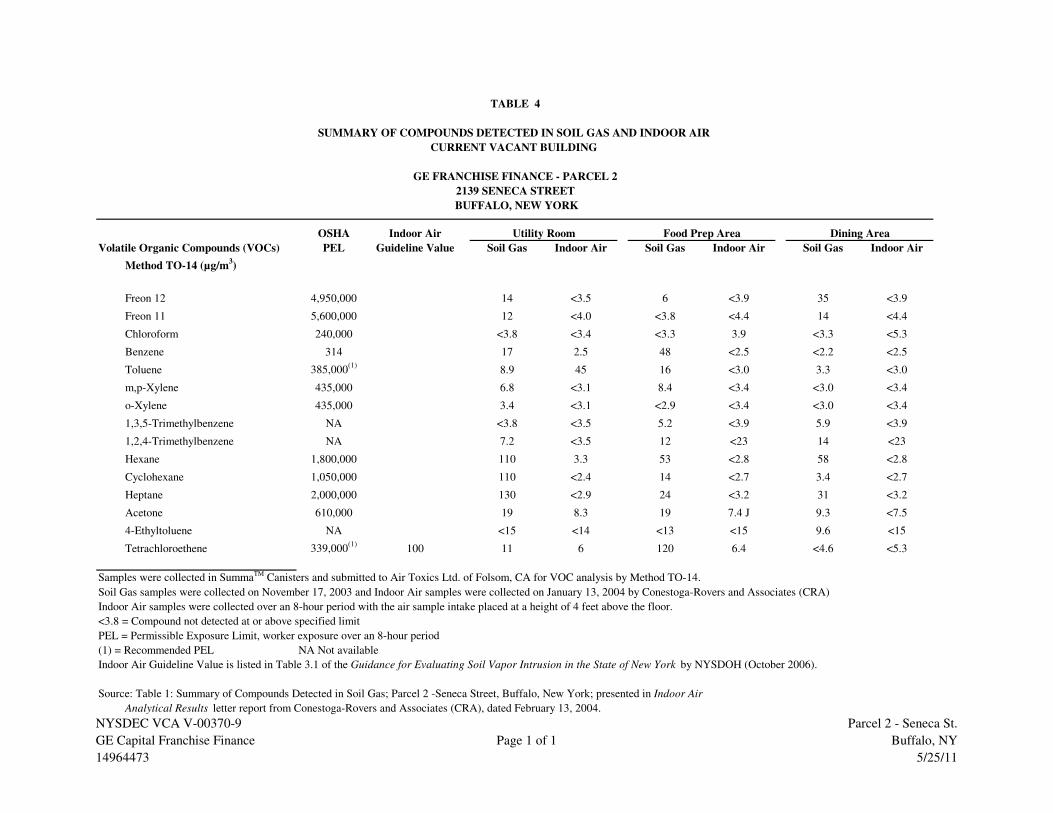
OSHA Indoor Air
Volatile Organic Compounds (VOCs) PEL Guideline Value Soil Gas Indoor Air Soil Gas Indoor Air Soil Gas Indoor Air
Method TO-14 (µg/m3)
Freon 12 4,950,000 14 <3.5 6 <3.9 35 <3.9
Freon 11 5,600,000 12 <4.0 <3.8 <4.4 14 <4.4
Chloroform 240,000 <3.8 <3.4 <3.3 3.9 <3.3 <5.3
Benzene 314 17 2.5 48 <2.5 <2.2 <2.5
Toluene 385,000(1)
8.9 45 16 <3.0 3.3 <3.0
m,p-Xylene 435,000 6.8 <3.1 8.4 <3.4 <3.0 <3.4
o-Xylene 435,000 3.4 <3.1 <2.9 <3.4 <3.0 <3.4
1,3,5-Trimethylbenzene NA <3.8 <3.5 5.2 <3.9 5.9 <3.9
1,2,4-Trimethylbenzene NA 7.2 <3.5 12 <23 14 <23
Hexane 1,800,000 110 3.3 53 <2.8 58 <2.8
Cyclohexane 1,050,000 110 <2.4 14 <2.7 3.4 <2.7
Heptane 2,000,000 130 <2.9 24 <3.2 31 <3.2
Acetone 610,000 19 8.3 19 7.4 J 9.3 <7.5
4-Ethyltoluene NA <15 <14 <13 <15 9.6 <15
Tetrachloroethene 339,000(1)
100 11 6 120 6.4 <4.6 <5.3
Samples were collected in SummaTM Canisters and submitted to Air Toxics Ltd. of Folsom, CA for VOC analysis by Method TO-14.
Soil Gas samples were collected on November 17, 2003 and Indoor Air samples were collected on January 13, 2004 by Conestoga-Rovers and Associates (CRA)
Indoor Air samples were collected over an 8-hour period with the air sample intake placed at a height of 4 feet above the floor.
<3.8 = Compound not detected at or above specified limit
PEL = Permissible Exposure Limit, worker exposure over an 8-hour period
(1) = Recommended PEL NA Not available
Indoor Air Guideline Value is listed in Table 3.1 of the Guidance for Evaluating Soil Vapor Intrusion in the State of New York by NYSDOH (October 2006).
Source: Table 1: Summary of Compounds Detected in Soil Gas; Parcel 2 -Seneca Street, Buffalo, New York; presented in Indoor Air
Analytical Results letter report from Conestoga-Rovers and Associates (CRA), dated February 13, 2004.
Utility Room Food Prep Area Dining Area
TABLE 4
SUMMARY OF COMPOUNDS DETECTED IN SOIL GAS AND INDOOR AIR
GE FRANCHISE FINANCE - PARCEL 2
2139 SENECA STREET
BUFFALO, NEW YORK
CURRENT VACANT BUILDING
NYSDEC VCA V-00370-9
GE Capital Franchise Finance
14964473
Page 1 of 1
Parcel 2 - Seneca St.
Buffalo, NY
5/25/11
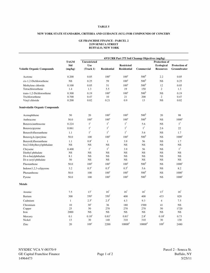
TAGM Unrestricted Protection of
Std Use Restricted Ecological Protection of
Volatile Organic Compounds (mg/kg) (Track 1) Residential Residential Commercial Resources Groundwater
Acetone 0.200 0.05 100a
100a
500b
2.2 0.05
cis-1,2-Dichloroethene NS 0.25 59 100a
500b
NS 0.25
Methylene chloride 0.100 0.05 51 100a
500b
12 0.05
Tetrachloroethene 1.4 1.3 5.5 19 150 2 1.3
trans-1,2-Dichloroethene 0.300 0.19 100a
100a
500b
NS 0.19
Trichloroethene 0.700 0.47 10 21 200 2 0.47
Vinyl chloride 0.200 0.02 0.21 0.9 13 NS 0.02
Semivolatile Organic Compounds
Acenaphthene 50 20 100a
100a
500b
20 98
Anthracene 50.0 100a
100a
100a
500b
NS 1000c
Benzo(a)anthracene 0.224 1c
1f
1f
5.6 NS 1f
Benzo(a)pyrene 0.061 1c
1f
1f
1f
2.6 22
Benzo(b)fluoranthene 1.1 1c
1f
1f
5.6 NS 1.7
Benzo(g,h,i)perylene 50.0 100 100a
100a
500b
NS 1000c
Benzo(k)fluoranthene 1.1 0.8c
1 3.9 56 NS 1.7
bis(2-Ethylhexyl)phthalate NS NS NS NS NS NS NS
Chrysene 0.400 1c
1f
3.9 56 NS 1f
Diethyl phthalate NS NS NS NS NS NS NS
Di-n-butylphthalate 8.1 NS NS NS NS NS NS
Di-n-octyl phthalate 50 NS NS NS NS NS NS
Fluoranthene 50.0 100a
100a
100a
500b
NS 1000c
Indeno(1,2,3-cd)pyrene 3.2 0.5c
0.5f
0.5f
5.6 NS 8.2
Phenanthrene 50.0 100 100a
100a
500b
NS 1000c
Pyrene 50.0 100 100a
100a
500b
NS 1000c
Metals
Arsenic 7.5 13c
16f
16f
16f
13f
16f
Barium 300 350c
350f
400 400 433 820
Cadmium 1 2.5c
2.5f
4.3 9.3 4 7.5
Chromium 10 30c
36 180 1500 41 NS
Copper 25 50 270 270 270 50 1720
Iron 2000 NS NS NS NS NS NS
Mercury 0.1 0.18c
0.81j
0.81j
2.8j
0.18j
0.73
Nickel 13 30 140 310 310 30 130
Zinc 20 109c
2200 10000d
10000d
109f
2480
6NYCRR Part 375 Soil Cleanup Objectives (mg/kg)
TABLE 5
NEW YORK STATE STANDARDS, CRITERIA AND GUIDANCE (SCG) FOR COMPOUNDS OF CONCERN
GE FRANCHISE FINANCE - PARCEL 2
2139 SENECA STREET
BUFFALO, NEW YORK
NYSDEC VCA V-00370-9
GE Capital Franchise Finance
14964473
Page 1 of 2
Parcel 2 - Seneca St.
Buffalo, NY
5/25/11

TAGM Std. = New York State Recommended Soil Cleanup Objective, Technical and Administrative Guidance
Memorandum (TAGM) #4046, January 24, 1994
mg/kg = milligrams per kilogram or parts per million (ppm)
NS = No Standard
a = The Soil Cleanup Objectives (SCOs) for residential, restricted-residential, and ecological use were
capped at a maximum value of 100 ppm. See TSD Section 9.3
b = The Soil Cleanup Objectives (SCOs) for commercial use were capped at a maximum value of 500 ppm.
See TSD Section 9.3
c = The SCOs for industrial use and the protection of groundwater were capped at a maximum value of 1,000 ppm.
See Section 9.3
d = The SCOs for metals were capped at a maximum value of 10,000 ppm. See TSD Section 9.3
j = This SCO is the lower of the values for mercury (elemental) or mercury (inorganic salts). See TSD Table 5.6-1
f = For constituents where the calculated SCO was lower than the rural soil background concentration as determined by
the Department of Health rural soil survey, the rural soil background concentration is used as the Track 2 SCO
value for this use of the site
TABLE 5 (Continued)
NYSDEC VCA V-00370-9
GE Capital Franchise Finance
14964473
Page 2 of 2
Parcel 2 - Seneca St.
Buffalo, NY
5/25/11

TAGM Unrestricted PPH
Volatile Organic Compounds Std Use Commercial DRS-1 DRS-18 DRS-19 DRS-2 DRS-3 DRS-30 DRS-31 DRS-4 DRS-13
(mg/kg; SW-846 8260) (ppm) (Track 1) East South-West South-East North-East North South-East South-West North-West West
Wall Wall Wall Wall Center Wall Wall Wall Wall Wall
Acetone 0.200 0.05 500b
<0.029 <0.03 <0.029 <0.029 <0.03 NA NA <0.029 <0.03
cis-1,2-Dichloroethene NS 0.25 500b
<0.006 0.018 <0.006 0.004 J 0.027 NA NA 0.005 J 0.068
Methylene chloride 0.100 0.05 500b
0.009 <0.009 <0.007 0.008 0.009 NA NA 0.008 0.006
Tetrachloroethene 1.4 1.3 150 0.016 0.5 D <0.006 0.56 D 0.003 J NA NA 7.5 D 4.2 D
trans-1,2-Dichloroethene 0.300 0.19 500b
<0.006 <0.006 <0.006 <0.006 0.002 J NA NA <0.006 <0.006
Trichloroethene 0.700 0.47 200 <0.006 0.032 <0.006 0.021 <0.006 NA NA 0.019 0.066
Vinyl chloride 0.200 0.02 13 <0.011 <0.012 <0.012 <0.012 0.002 J NA NA <0.012 <0.012
Semivolatile Organic Compounds
(mg/kg; SW-846 8270)
Acenaphthene 50 20 500b
<0.4 <0.4 <0.41 <7.6 <0.39 <2 <3.8 <0.39 <0.4
Anthracene 50.0 100a
500b
<0.4 <0.4 <0.41 3.4 J <0.39 1.0 J <3.8 <0.39 <0.4
Benzo(a)anthracene 0.224 1c
5.6 <0.4 <0.4 <0.41 7.7 <0.39 2.2 <3.8 <0.39 <0.4
Benzo(a)pyrene 0.061 1c
1f
<0.4 <0.4 <0.41 6.9 J <0.39 1.8 J <3.8 <0.39 <0.4
Benzo(b)fluoranthene 1.1 1c
5.6 <0.4 <0.4 <0.41 5.1 J <0.39 1.4 J <3.8 <0.39 <0.4
Benzo(g,h,i)perylene 50.0 100 500b
<0.4 <0.4 <0.41 <7.6 <0.39 <2 <3.8 <0.39 <0.4
Benzo(k)fluoranthene 1.1 0.8c
56 <0.4 <0.4 <0.41 6.5 J <0.39 1.3 J <3.8 <0.39 <0.4
bis(2-Ethylhexyl)phthalate NS NS NS <0.4 <0.4 <0.41 <7.6 <0.39 <2 <3.8 <0.39 <0.4
Chrysene 0.400 1c
56 <0.4 <0.4 <0.41 6.6 J <0.39 1.9 J <3.8 <0.39 <0.4
Diethyl phthalate NS NS NS <0.4 <0.4 <0.41 <7.6 <0.39 <2 <3.8 <0.39 <0.4
Di-n-butylphthalate 8.1 NS NS <0.4 <0.4 <0.41 <7.6 <0.39 <2 <3.8 <0.39 <0.4
Di-n-octyl phthalate 50 NS NS <0.55 <0.54 <0.56 <10.0 <0.53 <2.7 <5.2 <0.53 <0.55
Fluoranthene 50.0 100a
500b
<0.4 <0.4 <0.41 15 <0.39 3.6 <3.8 <0.39 <0.4
Indeno(1,2,3-cd)pyrene 3.2 0.5c
5.6 <0.4 <0.4 <0.41 <7.6 <0.39 <2 <3.8 <0.39 <0.4
Phenanthrene 50.0 100 500b
<0.4 <0.4 <0.41 13 <0.39 4 <3.8 <0.39 <0.4
Pyrene 50.0 100 500b
<0.4 <0.4 <0.41 14 <0.39 4.6 <3.8 <0.39 <0.4
SCOs Cleanup Objectives
Area B
Sample ID/Location
GE FRANCHISE FINANCE - PARCEL 2
2139 SENECA STREET
BUFFALO, NEW YORK
TABLE 6
ANALYTICAL RESULTS SUMMARY
SOIL SAMPLING - POST-EXCAVATION SAMPLING
OCTOBER AND NOVEMBER 2003
NYSDEC VCA V-00370-9
GE Capital Franchise Finance
14964473.00803
Page 1 of 6
Parcel 2 - Seneca St.
Buffalo, NY
5/25/11

TAGM Unrestricted PPH
Volatile Organic Compounds Std Use Commercial DRS-14 DRS-15 DRS-16 DRS-17 DRS-27 DRS-32 DRS-10 DRS-25 DRS-5 DRS-9
(mg/kg; SW-846 8260) (ppm) (Track 1) North West-North West-South South Bottom North-East North Bottom East West
Wall Wall Wall Wall Wall Wall Wall Wall
Acetone 0.200 0.05 500b
<0.03 <0.03 <0.029 <0.03 <0.029 <0.028 <0.03 <0.029 <0.03 <0.027
cis-1,2-Dichloroethene NS 0.25 500b
<0.006 <0.006 <0.006 <0.006 <0.006 <0.006 <0.006 0.018 0.015 <0.005
Methylene chloride 0.100 0.05 500b
0.007 0.006 0.006 0.006 0.005 J 0.007 0.008 0.017 0.013 0.007
Tetrachloroethene 1.4 1.3 150 0.023 0.073 0.210 2.8D 2.9 D 0.007 0.002 J 3.7 D 1.7 D 0.012
trans-1,2-Dichloroethene 0.300 0.19 500b
<0.006 <0.006 <0.006 <0.006 <0.006 <0.006 <0.006 <0.006 0.004 J <0.005
Trichloroethene 0.700 0.47 200 <0.006 0.005 J <0.006 0.004 J 0.004 J <0.006 <0.006 0.065 0.054 0.001 J
Vinyl chloride 0.200 0.02 13 <0.012 <0.012 <0.012 <0.012 <0.012 <0.011 <0.012 <0.011 <0.012 <0.011
Semivolatile Organic Compounds
(mg/kg; SW-846 8270)
Acenaphthene 50 20 500b
<0.39 <0.45 <0.4 <0.41 <0.4 <0.37 <0.4 <0.38 <0.4 <7.2
Anthracene 50.0 100a
500b
<0.39 <0.45 <0.4 <0.41 <0.4 <0.37 <0.4 <0.38 <0.4 <7.2
Benzo(a)anthracene 0.224 1c
5.6 <0.39 <0.45 <0.4 <0.41 <0.4 0.31 J <0.4 <0.38 <0.4 4.4 J
Benzo(a)pyrene 0.061 1c
1f
<0.39 <0.45 <0.4 <0.41 <0.4 0.27 J <0.4 <0.38 <0.4 4.0 J
Benzo(b)fluoranthene 1.1 1c
5.6 <0.39 <0.45 <0.4 <0.41 <0.4 0.29 J <0.4 <0.38 <0.4 3.5 J
Benzo(g,h,i)perylene 50.0 100 500b
<0.39 <0.45 <0.4 <0.41 <0.4 <0.37 <0.4 <0.38 <0.4 <7.2
Benzo(k)fluoranthene 1.1 0.8c
56 <0.39 <0.45 <0.4 <0.41 <0.4 0.24 J <0.4 <0.38 <0.4 <7.2
bis(2-Ethylhexyl)phthalate NS NS NS <0.39 <0.45 <0.4 <0.41 <0.4 0.24 J <0.4 <0.38 <0.4 <7.2
Chrysene 0.400 1c
56 <0.39 <0.45 <0.4 <0.41 <0.4 0.34 J <0.4 <0.38 <0.4 3.9 J
Diethyl phthalate NS NS NS <0.39 <0.45 <0.4 <0.41 <0.4 <0.37 <0.4 0.49 <0.4 <7.2
Di-n-butylphthalate 8.1 NS NS <0.39 <0.45 <0.4 <0.41 <0.4 <0.37 <0.4 <0.38 <0.4 <7.2
Di-n-octyl phthalate 50 NS NS <0.52 <0.61 <0.54 <0.55 <0.54 <0.5 <0.54 <0.51 <0.54 <9.7
Fluoranthene 50.0 100a
500b
<0.39 <0.45 <0.4 <0.41 <0.4 0.56 <0.4 <0.38 <0.4 8.4
Indeno(1,2,3-cd)pyrene 3.2 0.5c
5.6 <0.39 <0.45 <0.4 <0.41 <0.4 <0.37 <0.4 <0.38 <0.4 <7.2
Phenanthrene 50.0 100 500b
<0.39 <0.45 <0.4 <0.41 <0.4 0.32 J <0.4 <0.38 <0.4 5.7 J
Pyrene 50.0 100 500b
<0.39 <0.45 <0.4 <0.41 <0.4 0.53 <0.4 <0.38 <0.4 8.2 J
Area C
Sample ID/LocationSCOs Cleanup Objectives
Area D
TABLE 6 (Continued)
NYSDEC VCA V-00370-9
GE Capital Franchise Finance
14964473.00803
Page 2 of 6
Parcel 2 - Seneca St.
Buffalo, NY
5/25/11

TAGM Unrestricted PPH
Volatile Organic Compounds Std Use Commercial DRS-26 DRS-6 DRS-7 DRS-8 DRS-36 DRS-23 DRS-24 DRS-29
(mg/kg; SW-846 8260) (ppm) (Track 1) Bottom East North West Bottom North East Bottom
Wall Wall Wall Wall Wall
Acetone 0.200 0.05 500b
<0.028 <0.028 <0.028 <0.029 <0.031 <0.03 <0.03 0.042
cis-1,2-Dichloroethene NS 0.25 500b
<0.006 <0.006 <0.006 <0.006 <0.006 <0.006 <0.006 <0.006
Methylene chloride 0.100 0.05 500b
0.007 0.008 0.009 0.01 0.007 0.007 0.007 0.008
Tetrachloroethene 1.4 1.3 150 0.016 0.005 J 0.002 J 0.012 0.017 0.002 J 0.006 0.003 J
trans-1,2-Dichloroethene 0.300 0.19 500b
<0.006 <0.006 <0.006 <0.006 <0.006 <0.006 <0.006 <0.006
Trichloroethene 0.700 0.47 200 <0.006 <0.006 <0.006 <0.006 <0.006 <0.006 <0.006 <0.006
Vinyl chloride 0.200 0.02 13 <0.011 <0.011 <0.011 <0.012 <0.006 <0.012 <0.012 <0.012
Semivolatile Organic Compounds
(mg/kg; SW-846 8270)
Acenaphthene 50 20 500b
<7.6 <4.0 <0.39 <8.1 <0.41 <0.39 <0.39 <0.39
Anthracene 50.0 100a
500b
<7.6 <4.0 <0.39 <8.1 <0.41 <0.39 <0.39 <0.39
Benzo(a)anthracene 0.224 1c
5.6 4.4 J 2.8 J <0.39 <8.1 <0.41 <0.39 <0.39 <0.39
Benzo(a)pyrene 0.061 1c
1f
3.8 J 2.8 J <0.39 <8.1 <0.41 <0.39 <0.39 <0.39
Benzo(b)fluoranthene 1.1 1c
5.6 3.6 J 2.4 J <0.39 <8.1 <0.41 <0.39 <0.39 <0.39
Benzo(g,h,i)perylene 50.0 100 500b
<7.6 <4.0 <0.39 <8.1 <0.41 <0.39 <0.39 <0.39
Benzo(k)fluoranthene 1.1 0.8c
56 <7.6 2.4 J <0.39 <8.1 <0.41 <0.39 <0.39 <0.39
bis(2-Ethylhexyl)phthalate NS NS NS <7.6 <4.0 <0.39 <8.1 <0.41 <0.39 <0.39 <0.39
Chrysene 0.400 1c
56 4.0 J 2.7 J <0.39 <8.1 <0.41 <0.39 <0.39 <0.39
Diethyl phthalate NS NS NS <7.6 <4.0 <0.39 <8.1 <0.41 <0.39 <0.39 <0.39
Di-n-butylphthalate 8.1 NS NS <7.6 <4.0 <0.39 <8.1 <0.41 <0.39 <0.39 <0.39
Di-n-octyl phthalate 50 NS NS <10.0 <5.5 <0.52 <11.0 <0.55 <0.53 <0.53 <0.53
Fluoranthene 50.0 100a
500b
8.5 5.8 <0.39 5.0 J <0.41 <0.39 <0.39 <0.39
Indeno(1,2,3-cd)pyrene 3.2 0.5c
5.6 <7.6 <4.0 <0.39 <8.1 <0.41 <0.39 <0.39 <0.39
Phenanthrene 50.0 100 500b
6.0 J 4 <0.39 3.6 J <0.41 <0.39 <0.39 <0.39
Pyrene 50.0 100 500b
9.0 J 5.7 J <0.39 4.4 J <0.41 <0.39 <0.39 <0.39
Area FArea E
Sample ID/Location
TABLE 6 (Continued)
SCOs Cleanup Objectives
NYSDEC VCA V-00370-9
GE Capital Franchise Finance
14964473.00803
Page 3 of 6
Parcel 2 - Seneca St.
Buffalo, NY
5/25/11
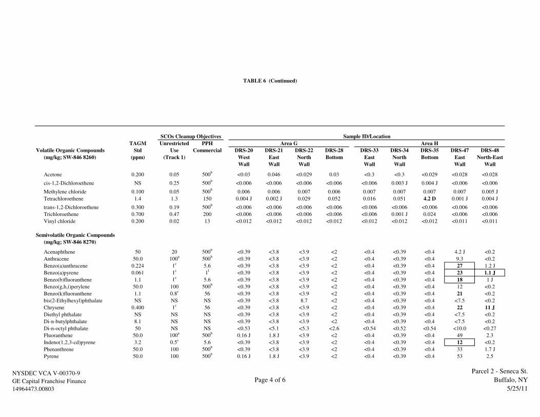
TAGM Unrestricted PPH
Volatile Organic Compounds Std Use Commercial DRS-20 DRS-21 DRS-22 DRS-28 DRS-33 DRS-34 DRS-35 DRS-47 DRS-48
(mg/kg; SW-846 8260) (ppm) (Track 1) West East North Bottom East North Bottom East North-East
Wall Wall Wall Wall Wall Wall Wall
Acetone 0.200 0.05 500b
<0.03 0.046 <0.029 0.03 <0.3 <0.3 <0.029 <0.028 <0.028
cis-1,2-Dichloroethene NS 0.25 500b
<0.006 <0.006 <0.006 <0.006 <0.006 0.003 J 0.004 J <0.006 <0.006
Methylene chloride 0.100 0.05 500b
0.006 0.006 0.007 0.006 0.007 0.007 0.007 0.007 0.005 J
Tetrachloroethene 1.4 1.3 150 0.004 J 0.002 J 0.029 0.052 0.016 0.051 4.2 D 0.001 J 0.004 J
trans-1,2-Dichloroethene 0.300 0.19 500b
<0.006 <0.006 <0.006 <0.006 <0.006 <0.006 <0.006 <0.006 <0.006
Trichloroethene 0.700 0.47 200 <0.006 <0.006 <0.006 <0.006 <0.006 0.001 J 0.024 <0.006 <0.006
Vinyl chloride 0.200 0.02 13 <0.012 <0.012 <0.012 <0.012 <0.012 <0.012 <0.012 <0.011 <0.011
Semivolatile Organic Compounds
(mg/kg; SW-846 8270)
Acenaphthene 50 20 500b
<0.39 <3.8 <3.9 <2 <0.4 <0.39 <0.4 4.2 J <0.2
Anthracene 50.0 100a
500b
<0.39 <3.8 <3.9 <2 <0.4 <0.39 <0.4 9.3 <0.2
Benzo(a)anthracene 0.224 1c
5.6 <0.39 <3.8 <3.9 <2 <0.4 <0.39 <0.4 27 1.2 J
Benzo(a)pyrene 0.061 1c
1f
<0.39 <3.8 <3.9 <2 <0.4 <0.39 <0.4 23 1.1 J
Benzo(b)fluoranthene 1.1 1c
5.6 <0.39 <3.8 <3.9 <2 <0.4 <0.39 <0.4 18 1 J
Benzo(g,h,i)perylene 50.0 100 500b
<0.39 <3.8 <3.9 <2 <0.4 <0.39 <0.4 12 <0.2
Benzo(k)fluoranthene 1.1 0.8c
56 <0.39 <3.8 <3.9 <2 <0.4 <0.39 <0.4 21 <0.2
bis(2-Ethylhexyl)phthalate NS NS NS <0.39 <3.8 8.7 <2 <0.4 <0.39 <0.4 <7.5 <0.2
Chrysene 0.400 1c
56 <0.39 <3.8 <3.9 <2 <0.4 <0.39 <0.4 22 11 J
Diethyl phthalate NS NS NS <0.39 <3.8 <3.9 <2 <0.4 <0.39 <0.4 <7.5 <0.2
Di-n-butylphthalate 8.1 NS NS <0.39 <3.8 <3.9 <2 <0.4 <0.39 <0.4 <7.5 <0.2
Di-n-octyl phthalate 50 NS NS <0.53 <5.1 <5.3 <2.6 <0.54 <0.52 <0.54 <10.0 <0.27
Fluoranthene 50.0 100a
500b
0.16 J 1.8 J <3.9 <2 <0.4 <0.39 <0.4 49 2.3
Indeno(1,2,3-cd)pyrene 3.2 0.5c
5.6 <0.39 <3.8 <3.9 <2 <0.4 <0.39 <0.4 12 <0.2
Phenanthrene 50.0 100 500b
<0.39 <3.8 <3.9 <2 <0.4 <0.39 <0.4 33 1.7 J
Pyrene 50.0 100 500b
0.16 J 1.8 J <3.9 <2 <0.4 <0.39 <0.4 53 2.5
Area G Area H
SCOs Cleanup Objectives
TABLE 6 (Continued)
Sample ID/Location
NYSDEC VCA V-00370-9
GE Capital Franchise Finance
14964473.00803
Page 4 of 6
Parcel 2 - Seneca St.
Buffalo, NY
5/25/11
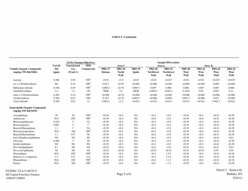
TAGM Unrestricted PPH
Volatile Organic Compounds Std Use Commercial DRS-37 DRS-38 DRS-39 DRS-44 DRS-45 DRS-40 DRS-41 DRS-42 DRS-43
(mg/kg; SW-846 8260) (ppm) (Track 1) Bottom North Spoils Northwest Northwest West West West West
Wall Wall Wall Wall Wall Wall Wall
Acetone 0.200 0.05 500b
<0.03 <3.8 <0.03 <0.03 <0.027 <0.03 <0.03 <0.032 <0.029
cis-1,2-Dichloroethene NS 0.25 500b
0.05 J <0.76 <0.006 <0.006 <0.005 <0.006 <0.006 0.009 <0.006
Methylene chloride 0.100 0.05 500b
0.006 J <0.76 0.005 J 0.007 0.006 0.006 0.007 0.007 0.008
Tetrachloroethene 1.4 1.3 150 72 D 3.9 51 D 0.005 J 0.002 J 0.18 D 0.09 0.047 0.11
trans-1,2-Dichloroethene 0.300 0.19 500b
<0.006 <0.76 <0.006 <0.006 <0.005 <0.006 <0.006 <0.006 <0.006
Trichloroethene 0.700 0.47 200 0.18 J <0.76 0.005 J <0.006 <0.005 0.001 J <0.006 0.011 <0.006
Vinyl chloride 0.200 0.02 13 0.002 J <1.5 <0.012 <0.012 <0.011 <0.012 <0.012 0.002 J <0.012
Semivolatile Organic Compounds
(mg/kg; SW-846 8270)
Acenaphthene 50 20 500b
<0.39 <0.4 NA <0.4 <3.8 <0.39 <0.4 <0.41 <0.38
Anthracene 50.0 100a
500b
<0.39 <0.4 NA <0.4 <3.8 <0.39 <0.4 <0.41 <0.38
Benzo(a)anthracene 0.224 1c
5.6 <0.39 <0.4 NA <0.4 <3.8 <0.39 <0.4 <0.41 <0.38
Benzo(a)pyrene 0.061 1c
1f
<0.39 <0.4 NA <0.4 <3.8 <0.39 <0.4 <0.41 <0.38
Benzo(b)fluoranthene 1.1 1c
5.6 <0.39 <0.4 NA <0.4 <3.8 <0.39 <0.4 <0.41 <0.38
Benzo(g,h,i)perylene 50.0 100 500b
<0.39 <0.4 NA <0.4 <3.8 <0.39 <0.4 <0.41 <0.38
Benzo(k)fluoranthene 1.1 0.8c
56 <0.39 <0.4 NA <0.4 <3.8 <0.39 <0.4 <0.41 <0.38
bis(2-Ethylhexyl)phthalate NS NS NS <0.39 <0.4 NA <0.4 <3.8 <0.39 <0.4 <0.41 0.63
Chrysene 0.400 1c
56 <0.39 <0.4 NA <0.4 <3.8 <0.39 <0.4 <0.41 <0.38
Diethyl phthalate NS NS NS <0.39 <0.4 NA <0.4 <3.8 <0.39 <0.4 <0.41 <0.38
Di-n-butylphthalate 8.1 NS NS <0.39 <0.4 NA <0.4 <3.8 <0.39 <0.4 <0.41 0.82
Di-n-octyl phthalate 50 NS NS <0.52 <0.54 NA <0.54 <0.52 <0.52 <0.54 0.55 0.94
Fluoranthene 50.0 100a
500b
<0.39 <0.4 NA <0.4 1.9 J <0.39 <0.4 <0.41 <0.38
Indeno(1,2,3-cd)pyrene 3.2 0.5c
5.6 <0.39 <0.4 NA <0.4 <3.8 <0.39 <0.4 <0.41 <0.38
Phenanthrene 50.0 100 500b
<0.39 <0.4 NA <0.4 1.1 J <0.39 <0.4 <0.41 <0.38
Pyrene 50.0 100 500b
<0.39 <0.4 NA <0.4 1.7 J <0.39 <0.4 <0.41 <0.38
Area K
SCOs Cleanup Objectives
Area JArea I
Sample ID/Location
TABLE 6 (Continued)
NYSDEC VCA V-00370-9
GE Capital Franchise Finance
14964473.00803
Page 5 of 6
Parcel 2 - Seneca St.
Buffalo, NY
5/25/11

Notes
Soil samples collected by Conestoga Rovers & Associates between October 21 and November 3, 2003
TAGM Std. = New York State Recommended Soil Cleanup Objective, Technical and Administrative Guidance Memorandum (TAGM) #4046, January 24, 1994
PPH = Protection of Public Health
GW = Groundwater
ppm = Parts per million
mg/kg = Milligrams per kilogram
NS = No Standard
NA = Not analyzed
b = The Soil Cleanup Objectives (SCOs) for commercial use were capped at a maximum value of 500 ppm. See TSD Section 9.3
c = The SCOs for industrial use and the protection of groundwater were capped at a maximum value of 1,000 ppm. See Section 9.3
f = For constituents where the calculated SCO was lower than the rural soil background concentration as determined by the Department of Health rural soil survey,
the rural soil background concentration is used as the Track 1 SCO value for this use of the site
<0.029 = Analyte not detected at the reporting limit shown
J = Estimated concentration
D = Diluted sample
Values in bold exceed TAGM Standards
7.7 = Values boxed and in bold exceed TAGM Standards and PPH Commercial Standards
Reference: Table C-1 in Appendix C of the Remediation Report
TABLE 6 (Continued)
NYSDEC VCA V-00370-9
GE Capital Franchise Finance
14964473.00803
Page 6 of 6
Parcel 2 - Seneca St.
Buffalo, NY
5/25/11

Parameters
Chlorinated Volatile Organic
Compounds (CVOCs) (mg/L)
cis-1,2-Dichloroethene 0.4 0.18 0.14 0.071 0.0093 0.13 0.14 0.0098 0.14 0.0052 0.027 0.074 0.14 D 0.085 D 0.023 0.039 0.19 0.011
Tetrachloroethene 0.69 J 0.05 0.085 0.07 0.016 0.11 0.04 0.0093 0.097 0.0046 0.025 0.073 0.062 <0.001 <0.001 <0.001 <0.001 <0.001
Trichloroethene 0.35 0.21 0.14 0.083 0.0067 0.086 0.022 0.0039 0.061 0.0043 0.018 0.037 0.028 <0.001 <0.001 0.00046 J 0.0025 <0.001
Vinyl Chloride <0.05 0.0045 J 0.005 J 0.0014 J <0.010 0.0017 J 0.0026 J <0.005 0.0018 J <0.001 <0.001 0.0016 0.0018 0.053 0.024 0.024 0.200 0.017
Metals (mg/L)
Calcium, total 143 - - - - - - - - - 50.4 - - 238 201 218 231 152 169 B
Iron, soluble - - - - - - - - - - 0.048 - - 1.08 7.88 11.9 5.85 7.88 3.35
Iron, total 1.01 - - - - - - - - - 29.5 - - 18.6 11.8 23.1 23.1 8.34 3.94
Manganese, total 1.94 - - - - - - - - - 0.87 - - 6.17 4.1 3.95 5.10 2.26 3.89
Sodium, total 204 - - - - - - - - - 157 - - 249 243 239 243 150 196
General Chemistry (mg/L)
Chloride - - - - - - 426 436 426 160 396 - 593 372 428 358 320 187 229 D
Nitrate-Nitrite - - - - - - - - - - - - - <0.05 <0.05 <0.05 <0.05 <0.05 <0.050
Sulfate - - - - - - - - - - 130 - - 15.4 106 114 130 95.9 133 D
Alkalinity, total - - - - - - - - - - 206 - - 732 620 810 824 470 587
Field Parameters
Oxidation-Reduction Potential (mV) - - - - - - - - - - -50 -127 - -270.2 -221.6 -75.4 -18.2 -128.2
Specific Conductance (mS/cm) 2.070 2.370 2.180 1.870 1.760 - - - - 2.190 2.180 2.390 2.170 1.730 1.801 1.536 1.559 1.358
pH (S.I.) 7.07 6.97 9.4† 7.0 7.0 - - - - 6.54 7.06 7.09 6.89 7.26 7.70 7.53 7.21 7.50
Temperature (Fahrenheit) 62.06 66.2 60.9 58.46 65.48 - - - - 57.2 56.0 57.2 44.2 55.3 58.1 48.8 49.6 57.7
Dissolved Oxygen (mg/L) - - - - - - - - - - 0 0 - 0.44 0.48 1.78 0.3 0.27
Permanganate (%) - - - - - - <0.0005 <0.0005 - - <0.0005 - <0.0005 - - - - -
Samples collected between January 2006 and June 2010 were collected by URS Corporation and analyzed by TestAmerica (formerly Severn Trent Laboratory [STL]), Buffalo, New York.
Samples collected between September 2000 and May 2005 were collected by CRA and analyzed by STL, Pittsburgh, PA.
J = Estimated concentration below reporting limit
D = Dilution required because concentration was above initial calibration range.
"-" = Data not available. Data was either not reported or samples were not collected for analysis.
† = pH measurements collected on 11/28/01 and 11/29/01 were anomalously high. Value suspected to be caused by instrument malfunction/calibration problems
Note: January 2006 permanganate measurements below 0.0005% are reported as <0.0005 with actual measurement reported below in parentheses.
**= MW-2 was re-sampled on August 11, 2009 for VOCs and Dehalococcoides bacteria only (field parameters were also collected). Results of the August 11, 2009 monitoring event
are presented with the June 23, 2009 event after the slash.
<0.001 / <0.001
<0.001 / <0.001
-144.7 / -99.3
1.887 / 2.120
7.66 / 6.79
4.19 / 0.0
- / -
10/5/2000 9/20/2001 11/29/2001 6/20/2002 9/24/2002 4/5/2004 1/12/2006 6/7/2006 3/20/2007
56.1 / 61.6
6/23/2009**
0.760 D/ 0.300 D
0.720 D/ 0.250 D
12/5/2007 6/30/20086/15/2004 10/14/2004 3/17/20095/26/2005 2/11/2010 6/24/2010
TABLE 7
ANALYTICAL RESULTS SUMMARY
GROUNDWATER SAMPLING
SEPTEMBER 2000 TO AUGUST 2010
GE FRANCHISE FINANCE - PARCEL 2
2139 SENECA STREET
BUFFALO, NEW YORK
MW-2
1/11/2005
NYSDEC VCA V-00370-9
GE Capital Franchise Finance
14964473.00803
Page 1 of 11
Parcel 2 - Seneca St.
Buffalo, NY
5/25/11
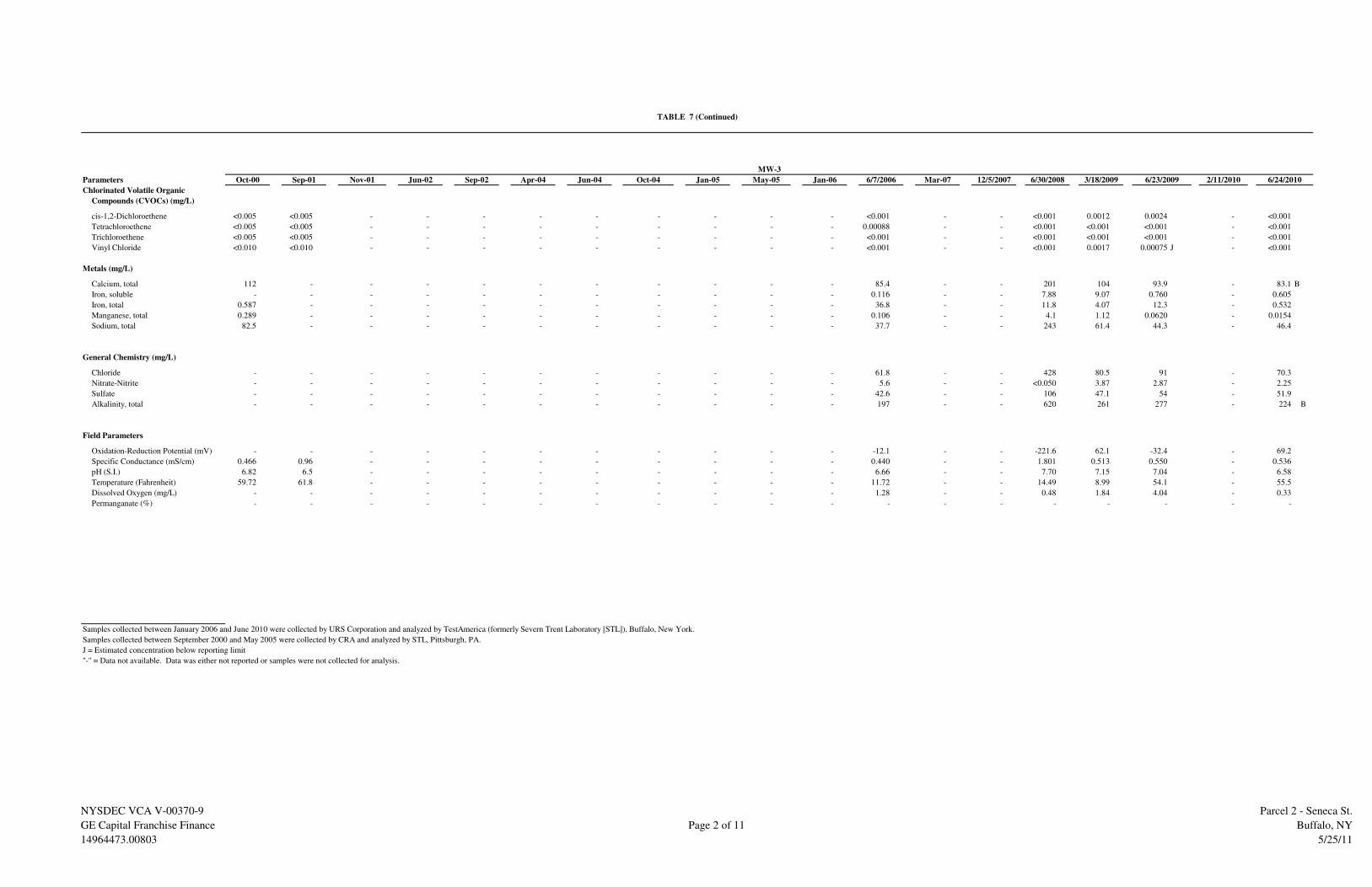
Parameters
Chlorinated Volatile Organic
Compounds (CVOCs) (mg/L)
cis-1,2-Dichloroethene <0.005 <0.005 - - - - - - - - - <0.001 - - <0.001 0.0012 0.0024 - <0.001
Tetrachloroethene <0.005 <0.005 - - - - - - - - - 0.00088 - - <0.001 <0.001 <0.001 - <0.001
Trichloroethene <0.005 <0.005 - - - - - - - - - <0.001 - - <0.001 <0.001 <0.001 - <0.001
Vinyl Chloride <0.010 <0.010 - - - - - - - - - <0.001 - - <0.001 0.0017 0.00075 J - <0.001
Metals (mg/L)
Calcium, total 112 - - - - - - - - - - 85.4 - - 201 104 93.9 - 83.1 B
Iron, soluble - - - - - - - - - - - 0.116 - - 7.88 9.07 0.760 - 0.605
Iron, total 0.587 - - - - - - - - - - 36.8 - - 11.8 4.07 12.3 - 0.532
Manganese, total 0.289 - - - - - - - - - - 0.106 - - 4.1 1.12 0.0620 - 0.0154
Sodium, total 82.5 - - - - - - - - - - 37.7 - - 243 61.4 44.3 - 46.4
General Chemistry (mg/L)
Chloride - - - - - - - - - - - 61.8 - - 428 80.5 91 - 70.3
Nitrate-Nitrite - - - - - - - - - - - 5.6 - - <0.050 3.87 2.87 - 2.25
Sulfate - - - - - - - - - - - 42.6 - - 106 47.1 54 - 51.9
Alkalinity, total - - - - - - - - - - - 197 - - 620 261 277 - 224 B
Field Parameters
Oxidation-Reduction Potential (mV) - - - - - - - - - - - -12.1 - - -221.6 62.1 -32.4 - 69.2
Specific Conductance (mS/cm) 0.466 0.96 - - - - - - - - - 0.440 - - 1.801 0.513 0.550 - 0.536
pH (S.I.) 6.82 6.5 - - - - - - - - - 6.66 - - 7.70 7.15 7.04 - 6.58
Temperature (Fahrenheit) 59.72 61.8 - - - - - - - - - 11.72 - - 14.49 8.99 54.1 - 55.5
Dissolved Oxygen (mg/L) - - - - - - - - - - - 1.28 - - 0.48 1.84 4.04 - 0.33
Permanganate (%) - - - - - - - - - - - - - - - - - - -
Samples collected between January 2006 and June 2010 were collected by URS Corporation and analyzed by TestAmerica (formerly Severn Trent Laboratory [STL]), Buffalo, New York.
Samples collected between September 2000 and May 2005 were collected by CRA and analyzed by STL, Pittsburgh, PA.
J = Estimated concentration below reporting limit
"-" = Data not available. Data was either not reported or samples were not collected for analysis.
6/23/2009Oct-04
MW-3
Nov-01 Jun-02 2/11/2010Jan-05 May-05 Jan-06 3/18/20096/7/2006 Mar-07 12/5/2007
TABLE 7 (Continued)
6/24/20106/30/2008Sep-02 Apr-04 Jun-04Oct-00 Sep-01
NYSDEC VCA V-00370-9
GE Capital Franchise Finance
14964473.00803
Page 2 of 11
Parcel 2 - Seneca St.
Buffalo, NY
5/25/11

Parameters
Chlorinated Volatile Organic
Compounds (CVOCs) (mg/L)
cis-1,2-Dichloroethene 0.25 J 0.0038 J 0.16 J 0.12 0.22 J 0.24 J 1.8 0.69 1.2 0.33 J 0.54 D 0.36 D 2.2 2.4 D 0.91 D 13 D 3.5 D 0.94 D
Tetrachloroethene 17 J 0.041 9.4 2.2 19 13 6 19 7.1 9.7 12 D 7.6 D 13 D <0.001 0.00047 J 0.0014 0.00051 J 0.0014
Trichloroethene 0.94 0.0065 0.58 0.33 1.5 0.83 3.7 2.4 2.8 1.7 2.8 D 3 D 3.8 0.0005 J 0.0014 J 0.0045 0.00085 J 0.00099 J
Vinyl Chloride <0.5 <0.01 <0.5 0.15 <0.5 0.0021 J <0.75 <1.0 <0.25 <0.5 0.0082 0.0064 J <0.1 1.4 D 0.78 D 3.3 D 1.7 D 1.0 D
Ethene - - - - - - - - - - <0.004 - - 1.00 - 0.98 - 0.26 <3.0
Methane - - - - - - - - - - 0.036 - - <0.50 - 4.20 - 6.50 13.0
Ethane - - - - - - - - - - 0.015 - - <0.75 - 0.24 - 0.25 <3.0
Metals (mg/L)
Calcium, total 130 - - - - - - - - - 246 - - 299 168 174 156 196 189 B
Iron, soluble - - - - - - - - - - 1.02 - - 2.24 5.79 13.9 7.35 7.84 17.1
Iron, total 1.11 - - - - - - - - - 55.3 - - 17.2 12.3 38.4 18.5 8.4 16.2
Manganese, total 0.823 - - - - - - - - - 3.56 - - 12.9 8.5 3.17 3.21 4.42 4.10
Sodium, total 162 - - - - - - - - - 210 - - 208 200 210 189 188 203
General Chemistry (mg/L)
Chloride - - - - - 354 J 311 337 273 237 376 - 225 292 301 331 230 278 289 D
Nitrate-Nitrite - - - - - - - - - - - - - <0.05 <0.05 <0.05 <0.05 <0.05 <0.050
Sulfate - - - - - - - - - - 899 - - 143 394 112 330 236 174 D
Alkalinity, total - - - - - - - - - - 362 - - 987 401 714 410 520 587
Field Parameters
Oxidation-Reduction Potential (mV) - - - - - - - - - - -73 -268 - -191.2 -205.2 -24.0 -28.8
Specific Conductance (mS/cm) 2.21 0.410 1.590 1.72 1.67 - - - - 1.95 3.42 1.41 1.23 1.68 1.388 1.353 1.508
pH (S.I.) 6.90 6.93 11.3† 7.4 6.8 - - - - 6.26 6.69 7.5 6.89 7.36 7.86 7.55 7.36
Temperature (Fahrenheit) 62.24 65.1 61.7 - 63.5 - - - - 54.68 57.6 57.7 43.3 58.7 56.7 45.9 50.0
Dissolved Oxygen (mg/L) - - - - - - - - - - 0.2 0 - 3.39 0.53 5.22 0.69
Permanganate (%) - - - - - - - <0.0005 - <0.0005 - - - -
(0.00008) (0.00002)
Samples collected between January 2006 and June 2010 were collected by URS Corporation and analyzed by TestAmerica (formerly Severn Trent Laboratory [STL]), Buffalo, New York.
Samples collected between September 2000 and May 2005 were collected by CRA and analyzed by STL, Pittsburgh, PA.
J = Estimated concentration below reporting limit
D = Dilution required because concentration was above initial calibration range.
"-" = Data not available. Data was either not reported or samples were not collected for analysis.
* = Duplicate samples were collected from the well during this event; value shown is the higher concentration.
† = pH measurements collected on 11/28/01 and 11/29/01 were anomalously high. Value suspected to be caused by instrument malfunction/calibration problems
Note: January 2006 permanganate measurements below 0.0005% are reported as <0.0005 with actual measurement reported below in parentheses.
**= Field parameters for MW-4 were collected on August 11, 2009 and are presented with the June 23, 2009 event after the slash.
***= MW-4 was re-sampled on August 11, 2009 for VOCs; VOC results and field measurements are presented with the June 23, 2010 event after the slash.
0.21 / 0.31
- / -
-120.8 / -77.8
1.652 / 1.528
7.22 / 7.87
59.6 / 63.4
12/5/2007* 3/17/2009*
2.8 D / 1.5 D
3.5 D / 1.3 D
0.0019 / <0.025
0.0022 / <0.025
10/5/2000* 2/11/2010*
7.86 / 6.42 **
55.67 / 61.88 **
11/28/2001* 6/19/2002 6/7/2006 3/20/2007
0.00 / 0.79 **
1.277 / 1.866 **
6/23/2009*9/24/2001 9/25/2002* 4/5/2004 6/16/2004* 10/15/2004* 1/11/2005* 5/26/2005*
- / -
6/30/2008*
-126.2 / -99.0 **
<0.0005
1/12/2006
<0.0005 <0.0005
6/23/2010***
TABLE 7 (Continued)
MW-4
NYSDEC VCA V-00370-9
GE Capital Franchise Finance
14964473.00803
Page 3 of 11
Parcel 2 - Seneca St.
Buffalo, NY
5/25/11

Parameters
Chlorinated Volatile Organic
Compounds (CVOCs) (mg/L)
cis-1,2-Dichloroethene - <0.005 - - - - - - - - - - - <0.001 <0.001 0.00063 J 0.005 <0.001 <0.001
Tetrachloroethene - <0.005 - - - - - - - - - - - <0.001 <0.001 <0.001 <0.001 <0.001 <0.001
Trichloroethene - <0.005 - - - - - - - - - - - <0.001 <0.001 <0.001 <0.001 <0.001 <0.001
Vinyl Chloride - <0.01 - - - - - - - - - - - <0.001 <0.001 0.00068 J 0.0024 <0.001 <0.001
Metals (mg/L)
Calcium, total - - - - - - - - - - - - - 173 164 131 153 147 132 B
Iron, soluble - - - - - - - - - - - - - 0.0567 0.795 2.36 1.51 <0.05 0.099
Iron, total - - - - - - - - - - - - - 1.21 3.59 0.590 4.79 1.9 0.645
Manganese, total - - - - - - - - - - - - - 1.55 1.58 0.929 1.66 0.807 1.43
Sodium, total - - - - - - - - - - - - - 147 149 113 138 150 136
General Chemistry (mg/L)
Chloride - - - - - - - - - - - - - 305 322 285 290 268 231 D
Nitrate-Nitrite - - - - - - - - - - - - - <0.05 <0.05 0.03 J <0.05 <0.05 <0.050
Sulfate - - - - - - - - - - - - - 200 175 140 160 146 132 D
Alkalinity, total - - - - - - - - - - - - - 278 300 329 292 277 278
Field Parameters
Oxidation-Reduction Potential (mV) - - - - - - - - - - - - - 11.4 75.2 63.1 -22.5 76.8 95.7
Specific Conductance (mS/cm) - 1.630 - - - - - - - - - - - 0.552 0.802 1.074 1.227 1.586 1.139
pH (S.I.) - 6.56 - - - - - - - - - - - 7.81 6.57 6.65 7.02 6.44 6.41
Temperature (Fahrenheit) - 63.9 - - - - - - - - - - - 59.0 56.6 51.9 57.2 51.3 60.2
Dissolved Oxygen (mg/L) - - - - - - - - - - - - - 4.08 1.10 1.82 4.68 1.02 0.48
Permanganate (%) - - - - - - - - - - - - - - - - - - -
Samples collected between January 2006 and June 2010 were collected by URS Corporation and analyzed by TestAmerica (formerly Severn Trent Laboratory [STL]), Buffalo, New York.
Samples collected between September 2000 and May 2005 were collected by CRA and analyzed by STL, Pittsburgh, PA.
J = Estimated concentration below reporting limit
D = Dilution required because concentration was above initial calibration range.
"-" = Data not available. Data was either not reported or samples were not collected for analysis.
* = Duplicate samples were collected from the well during this event; value shown is the higher concentration.
Note: January 2006 permanganate measurements below 0.0005% are reported as <0.0005 with actual measurement reported below in parentheses.
Jan-06 6/23/2009Nov-01 Jun-02 Sep-02 Apr-04 2/11/20106/30/2008 3/18/2009Jan-05 May-05Oct-00 9/24/2001* Mar-07 12/5/2007Jun-06Jun-04 Oct-04
TABLE 7 (Continued)
MW-6
6/24/2010
NYSDEC VCA V-00370-9
GE Capital Franchise Finance
14964473.00803
Page 4 of 11
Parcel 2 - Seneca St.
Buffalo, NY
5/25/11

Parameters
Chlorinated Volatile Organic
Compounds (CVOCs) (mg/L)
cis-1,2-Dichloroethene - <0.005 - - - <0.005 <0.005 <0.005 <0.005 <0.001 <0.001 - - <0.001 <0.001 0.00033 J 0.0091 J 0.00056 J <0.001
Tetrachloroethene - <0.005 - - - 0.0012 J <0.005 <0.005 <0.005 <0.001 0.00068 J - - <0.001 <0.001 <0.001 <0.001 <0.001 <0.001
Trichloroethene - <0.005 - - - <0.005 <0.005 <0.005 <0.005 <0.001 <0.001 - - <0.001 <0.001 <0.001 <0.001 <0.001 <0.001
Vinyl Chloride - <0.01 - - - <0.01 <0.01 <0.005 <0.005 <0.001 <0.001 - - <0.001 <0.001 <0.001 <0.001 <0.001 <0.001
Metals (mg/L)
Calcium, total - - - - - - - - - - - - - 135 139 160 139 145 146 B
Iron, soluble - - - - - - - - - - - - - 1.79 3.87 3.32 2.68 0.396
Iron, total - - - - - - - - - - - - - 3.87 9.76 0.579 3.93 0.585 0.639
Manganese, total - - - - - - - - - - - - - 1.94 1.98 2.27 1.89 1.74 1.65
Sodium, total - - - - - - - - - - - - - 443 399 353 397 406 400
General Chemistry (mg/L)
Chloride - - - - - - - - - - - - - 996 802 936 780 807 775 D
Nitrate-Nitrite - - - - - - - - - - - - - <0.05 <0.05 0.04 J <0.05 <0.05 <0.050
Sulfate - - - - - - - - - - - - - 79.7 71.4 71.2 66 83.9 69.9
Alkalinity, total - - - - - - - - - - - - - 174 178 241 177 185 195
Field Parameters
Oxidation-Reduction Potential (mV) - - - - - - - - - - -28 - - 19.5 26.4 70.6 -10.8 80.5 96.8
Specific Conductance (mS/cm) - 2.100 - - - - - - - 3.02 3.62 - - 1.912 1.998 1.846 1.961 2.871 2.152
pH (S.I.) - 6.69 - - - - - - - 6.09 6.69 - - 6.87 6.46 6.93 6.90 6.46 6.27
Temperature (Fahrenheit) - 61.8 - - - - - - - 52.52 56.5 - - 54.0 55.4 48.6 56.5 49.3 57.4
Dissolved Oxygen (mg/L) - - - - - - - - - - 0 - - 2.25 0.97 1.67 3.26 0.78 0.31
Permanganate (%) - - - - - - - - - - - - - - - - - - -
Samples collected between January 2006 and June 2010 were collected by URS Corporation and analyzed by TestAmerica (formerly Severn Trent Laboratory [STL]), Buffalo, New York.
Samples collected between September 2000 and May 2005 were collected by CRA and analyzed by STL, Pittsburgh, PA.
J = Estimated concentration below reporting limit
D = Dilution required because concentration was above initial calibration range.
"-" = Data not available. Data was either not reported or samples were not collected for analysis.
3/18/20096/30/2008 2/11/20106/23/2009Oct-00 9/24/2001 4/5/2004 6/14/2004 5/26/2005 1/12/2006 Mar-071/11/2005Nov-01 Jun-02 Sep-02 10/13/2004 Jun-06 12/5/2007
TABLE 7 (Continued)
MW-7
6/24/2010
NYSDEC VCA V-00370-9
GE Capital Franchise Finance
14964473.00803
Page 5 of 11
Parcel 2 - Seneca St.
Buffalo, NY
5/25/11

Parameters
Chlorinated Volatile Organic
Compounds (CVOCs) (mg/L)
cis-1,2-Dichloroethene - 0.0043 J 0.029 J 0.002 J 0.018 J 0.15 J 0.99 0.0021 0.01 0.19 J 0.016 0.0016 0.023 0.54 D 0.58 D 0.330 D 0.027 0.0024 0.013
Tetrachloroethene - 0.24 1.7 0.022 J 1 8.3 6.1 0.0054 0.15 3.4 0.39 D 0.0083 0.49 D 0.00054 J <0.001 <0.001 <0.001 <0.001 <0.001
Trichloroethene - 0.012 0.084 0.0034 J 0.081 0.54 1.5 0.0016 0.021 0.64 0.038 0.0016 0.044 0.0029 J 0.0011 0.001 J <0.001 <0.001 <0.001
Vinyl Chloride - <0.02 <0.01 <0.01 <0.1 <1.0 <0.5 <0.005 <0.005 <0.2 <0.001 <0.001 <0.001 0.88 D 0.84 D 0.590 D 0.070 0.016 0.049
Ethene - - - - - - - - - - <0.005 - - - - 0.22 - 1.00 <1.5
Methane - - - - - - - - - - 0.035 - - - - 5.00 - 14.00 14.0
Ethane - - - - - - - - - - <0.005 - - - - 0.31 - 0.98 <1.5
Metals (mg/L)
Calcium, total - - - - - - - - - - 175 - - 168 169 187 175 154 158 B
Iron, soluble - - - - - - - - - - - - - 31.5 32.9 29.9 32.4 21.8 22.7
Iron, total - - - - - - - - - - 3.59 - - 69.4 29.8 40 50.5 22.9 26.0
Manganese, total - - - - - - - - - - 1.03 - - 4.39 4.13 5.17 4.75 3.23 3.37
Sodium, total - - - - - - - - - - 217 - - 266 224 203 209 224 208
General Chemistry (mg/L)
Chloride - - - - - 343 325 210 243 297 468 - 236 466 490 358 380 279 279 D
Nitrate-Nitrite - - - - - - - - - - - - - <0.05 <0.05 <0.05 <0.05 <0.05 <0.050
Sulfate - - - - - - - - - - 606 - - 108 222 92.3 180 22.1 63.5
Alkalinity, total - - - - - - - - - - 247 - - 340 370 728 472 661 599
Field Parameters
Oxidation-Reduction Potential (mV) - - - - - - - - - - 6 50 - -135.3 -135.1 -44.6 -84.6 -113.5
Specific Conductance (mS/cm) - 780 1.150 1.55 1.56 - - - - 1.90 2.23 1.87 1.51 1.66 1.659 1.507 2.073 1.570
pH (S.I.) - 6.94 10.7† 7.3 6.7 - - - - 6.30 6.76 6.83 6.69 7.03 6.69 7.20 7.20 7.31
Temperature (Fahrenheit) - 62.8 60.2 - 64.04 - - - - 53.42 57.0 57.0 45 56.7 56.3 49.9 52.0 58.0
Dissolved Oxygen (mg/L) - - - - - - - - - - 0 0.93 - 3.4 0.49 0.96 0.27 0.16
Permanganate (%) - - - - - - <0.0005 <0.0005 <0.0005 - <0.0005 - <0.0005 - - - - -
(0.00002)
Samples collected between January 2006 and June 2010 were collected by URS Corporation and analyzed by TestAmerica (formerly Severn Trent Laboratory [STL]), Buffalo, New York.
Samples collected between September 2000 and May 2005 were collected by CRA and analyzed by STL, Pittsburgh, PA.
J = Estimated concentration below reporting limit
D = Dilution required because concentration was above initial calibration range.
"-" = Data not available. Data was either not reported or samples were not collected for analysis.
* = Duplicate samples were collected from the well during this event; value shown is the higher concentration.
† = pH measurements collected on 11/28/01 and 11/29/01 were anomalously high. Value suspected to be caused by instrument malfunction/calibration problems
Note: January 2006 permanganate measurements below 0.0005% are reported as <0.0005 with actual measurement reported below in parentheses.
**= MW-11 was sampled on August 11, 2009 for Dehalococcoides bacteria only (field parameters were also collected). Results of the August 11, 2009 monitoring event
field parameters are presented with the June 23, 2009 event after the slash.
58.0 / 62.6**
2/11/2010*
2.16 / 0.70**
- / -
-127.9 / -132.0**
2.172 / 1.804**
7.34 / 6.69**
6/23/2009*Oct-00 9/21/2001 11/28/2001 6/19/2002* 5/26/2005 1/12/2006 6/7/2006 3/20/2007 12/5/2007*4/6/2004 6/15/2004 10/15/20049/25/2002
TABLE 7 (Continued)
MW-11
6/23/20106/30/2008* 3/17/2009*1/10/2005
NYSDEC VCA V-00370-9
GE Capital Franchise Finance
14964473.00803
Page 6 of 11
Parcel 2 - Seneca St.
Buffalo, NY
5/25/11

Parameters
Chlorinated Volatile Organic
Compounds (CVOCs) (mg/L)
cis-1,2-Dichloroethene - - - - - 0.0063 0.0053 J 0.0059 0.0039 J 0.017 J 0.017 0.023 0.028 1.0 D 0.018 0.031 0.0023 0.019 0.0055
Tetrachloroethene - - - - - 0.19 0.25 0.27 0.13 0.56 0.47 D 0.79 1.2 D <0.01 <0.001 <0.001 <0.001 <0.001 <0.001
Trichloroethene - - - - - 0.016 0.015 0.014 0.0096 0.044 J 0.039 0.048 0.066 <0.01 <0.0047 <0.001 <0.001 <0.001 <0.001
Vinyl Chloride - - - - - <0.01 <0.02 <0.012 <0.005 <0.05 <0.001 <0.001 <0.008 0.33 0.02 0.007 0.002 0.029 0.0088
Metals (mg/L)
Calcium, total - - - - - - - - - - 62.4 - - 181 121 127 146 132 116 B
Iron, soluble - - - - - - - - - - 0.0176 - - 53.8 14.1 33.9 29.4 43.7 40.7
Iron, total - - - - - - - - - - 2.58 - - 87.1 53.2 76.8 59.1 43.7 40.5
Manganese, total - - - - - - - - - - 0.236 - - 3.96 2.21 2.00 1.95 1.79 1.59
Sodium, total - - - - - - - - - - 78.9 - - 114 103 96.5 133 121 98.6
General Chemistry (mg/L)
Chloride - - - - - 119 J 133 35.7 49 212 138 - 205 144 203 165 240 196 149 D
Nitrate-Nitrite - - - - - - - - - - 0.46 - - <0.05 <0.05 <0.05 <0.05 0.024 J <0.050
Sulfate - - - - - - - - - - 104 - - - 140 107 89 129 118 D
Alkalinity, total - - - - - - - - - - 142 - - 702 285 390 418 314 284
Field Parameters
Oxidation-Reduction Potential (mV) - - - - - - - - - - 142 126 - -172.9 -74.6 -34.9 -128.5 -30.1 -92.4
Specific Conductance (mS/cm) - - - - - - - - - 1.45 1 1.44 1.17 1.23 0.995 0.947 1.185 1.432 0.932
pH (S.I.) - - - - - - - - - 6.04 6.69 6.63 6.74 6.99 6.91 7.01 7.13 6.71 6.78
Temperature (Fahrenheit) - - - - - - - - - 53.96 57.7 55.1 44.2 56.2 56.5 51.5 56.1 53.4 57.3
Dissolved Oxygen (mg/L) - - - - - - - - - - 0 0 - 0.46 0.60 2.80 3.15 0.3 0.22
Permanganate (%) - - - - - - - - - - 0.00065 - <0.0005 - - - - - -
Samples collected between January 2006 and June 2010 were collected by URS Corporation and analyzed by TestAmerica (formerly Severn Trent Laboratory [STL]), Buffalo, New York.
Samples collected between September 2000 and May 2005 were collected by CRA and analyzed by STL, Pittsburgh, PA.
J = Estimated concentration below reporting limit
D = Dilution required because concentration was above initial calibration range.
"-" = Data not available. Data was either not reported or samples were not collected for analysis.
6/23/2009 2/11/2010Oct-00 Sep-01 Sep-02 3/17/200912/5/2007 6/30/20081/10/2005 6/7/2006 3/20/20074/5/2004 10/13/2004Jun-02 6/24/2010
TABLE 7 (Continued)
MW-13
6/15/2004 5/25/2005 1/12/2006Nov-01
NYSDEC VCA V-00370-9
GE Capital Franchise Finance
14964473.00803
Page 7 of 11
Parcel 2 - Seneca St.
Buffalo, NY
5/25/11

Parameters
Chlorinated Volatile Organic
Compounds (CVOCs) (mg/L)
cis-1,2-Dichloroethene - - - - - - - - - - 1.2 D 0.26 D - 9.3 D 7.1 D 0.018 D - - -
Tetrachloroethene - - - - - - - - - - 7.3 D 6.8 D - 0.042 0.0062 0.0022 J,D - - -
Vinyl Chloride - - - - - - - - - - 0.05 0.0025 - 9.9 D 8.2 D 0.0028 J,D - - -
Metals (mg/L)
Calcium, total - - - - - - - - - - - - - 143 173 92.4 - - -
Iron, soluble - - - - - - - - - - - - - 17.4 13.6 8.78 - - -
Iron, total - - - - - - - - - - - - - 47.3 50.5 62.0 - - -
Manganese, total - - - - - - - - - - - - - 22.1 25.6 54.0 - - -
Sodium, total - - - - - - - - - - - - - 195 159 125 - - -
General Chemistry (mg/L)
Chloride - - - - - - - - - - - - - 362 345 234 - - -
Nitrate-Nitrite - - - - - - - - - - - - - <0.05 <0.05 <0.05 - - -
Sulfate - - - - - - - - - - - - - 2.3 170 103 - - -
Alkalinity, total - - - - - - - - - - - - - 506 491 567 - - -
Field Parameters
Oxidation-Reduction Potential (mV) - - - - - - - - - - 125 107 - -192.3 -116.3 -36.2 - - -
Specific Conductance (mS/cm) - - - - - - - - - - 1.94 2.21 - 1.7 1.473 1.472 - - -
pH (S.I.) - - - - - - - - - - 6.84 6.75 - 7.34 7.14 7.14 - - -
Temperature (Fahrenheit) - - - - - - - - - - 57.8 59.5 - 58.7 57.1 49.0 - - -
Dissolved Oxygen (mg/L) - - - - - - - - - - 0 0 - 3.41 0.21 1.21 - - -
Permanganate (%) - - - - - - - - - - - - - - - - - - -
Samples collected between January 2006 and June 2010 were collected by URS Corporation and analyzed by TestAmerica (formerly Severn Trent Laboratory [STL]), Buffalo, New York.
Samples collected between September 2000 and May 2005 were collected by CRA and analyzed by STL, Pittsburgh, PA.
J = Estimated concentration below reporting limit
D = Dilution required because concentration was above initial calibration range.
"-" = Data not available. Data was either not reported or samples were not collected for analysis.
May-05 1/12/2006 2/11/201012/5/2007 6/30/2008 6/23/20093/17/2009Oct-00 Sep-01 Nov-01 Jun-02 Sep-02 Apr-04 Jun-04 Oct-04 Jan-05
TABLE 7 (Continued)
IW-2S
6/7/2006 Mar-07 6/23/2010
NYSDEC VCA V-00370-9
GE Capital Franchise Finance
14964473.00803
Page 8 of 11
Parcel 2 - Seneca St.
Buffalo, NY
5/25/11

Parameters
Chlorinated Volatile Organic
Compounds (CVOCs) (mg/L)
cis-1,2-Dichloroethene - - - - - - - - - - - 0.21 D - 4.2 D 1.4 0.420 D 0.150 0.043 0.065
Tetrachloroethene - - - - - - - - - - - 1.5 D - 0.0059 0.015 <0.010 D <0.001 <0.001 0.00053 J
Trichloroethene - - - - - - - - - - - 0.24 D - 0.01 0.0076 <0.010 D 0.00077 J 0.00088 J 0.00076 J
Vinyl Chloride - - - - - - - - - - - 0.00096 J - 3.0 D 0.77 0.690 D 0.200 0.093 0.15
Metals (mg/L)
Calcium, total - - - - - - - - - - - - - 267 209 182 193 159 160 B
Iron, soluble - - - - - - - - - - - - - 217 35 52.1 19.7 20.7 19.8
Iron, total - - - - - - - - - - - - - 69.2 91.5 30.1 62.7 22.1 19.8
Manganese, total - - - - - - - - - - - - - 24 14 6.33 7.21 4.56 4.54
Sodium, total - - - - - - - - - - - - - 191 168 173 200 217 206
General Chemistry (mg/L)
Chloride - - - - - - - - - - - - - 313 279 268 280 287 274 D
Nitrate-Nitrite - - - - - - - - - - - - - <0.05 <0.05 <0.05 <0.058 <0.05 <0.050
Sulfate - - - - - - - - - - - - - 104 124 99.1 200 31.9 69.9
Alkalinity, total - - - - - - - - - - - - - 761 709 806 609 649 597
Field Parameters
Oxidation-Reduction Potential (mV) - - - - - - - - - - - 24 - -132.8 -143.3 -46.5 -136.5 -98.7 -130.7
Specific Conductance (mS/cm) - - - - - - - - - - - 1.84 - 1.67 1.558 1.449 1.640 2.071 1.541
pH (S.I.) - - - - - - - - - - - 6.77 - 7.16 6.52 7.13 7.68 7.12 7.22
Temperature (Fahrenheit) - - - - - - - - - - - 57.5 - 56.4 56.1 50.6 59.7 52.5 57.9
Dissolved Oxygen (mg/L) - - - - - - - - - - - 0 - 1.4 2.97 2.72 2.04 0.38 0.15
Permanganate (%) - - - - - - - - - - - - - - - - - - -
Samples collected between January 2006 and June 2010 were collected by URS Corporation and analyzed by TestAmerica (formerly Severn Trent Laboratory [STL]), Buffalo, New York.
Samples collected between September 2000 and May 2005 were collected by CRA and analyzed by STL, Pittsburgh, PA.
J = Estimated concentration below reporting limit
D = Dilution required because concentration was above initial calibration range.
"-" = Data not available. Data was either not reported or samples were not collected for analysis.
6/23/2009Sep-01 Nov-01 Jun-02Oct-00 Jun-04 Oct-04 2/11/2010Sep-02 Apr-04
TABLE 7 (Continued)
6/23/20103/18/20096/7/2006 Mar-07 12/5/2007
PZ-A
6/30/2008Jan-05 May-05 Jan-06
NYSDEC VCA V-00370-9
GE Capital Franchise Finance
14964473.00803
Page 9 of 11
Parcel 2 - Seneca St.
Buffalo, NY
5/25/11

Parameters
Chlorinated Volatile Organic
Compounds (CVOCs) (mg/L)
cis-1,2-Dichloroethene 0.0076 0.033 0.046 0.11 0.0064 0.06 0.041 0.057 0.028 0.017 0.015 0.024 0.02 0.016 0.0098 0.064 0.0089 0.0068 0.0057
Tetrachloroethene 0.73 0.065 0.032 0.0071 0.02 0.0015 J 0.00095 J <0.005 <0.005 0.00018 J 0.00051 J 0.0045 0.028 <0.001 <0.001 <0.001 <0.001 <0.001 <0.001
Trichloroethene 0.03 0.27 0.095 0.025 0.022 0.0027 J 0.0016 J <0.005 0.0015 J 0.00063 J 0.003 0.0045 0.012 <0.001 <0.001 <0.001 <0.001 <0.001 <0.001
Vinyl Chloride <0.01 <0.01 <0.01 <0.01 <0.01 0.0063 J 0.012 0.046 0.038 0.019 0.019 0.014 0.0085 0.013 0.015 0.017 0.0053 0.008 0.014
Metals (mg/L)
Calcium, total 74.7 - - - - - - - - - 58.4 - - 29.4 31.2 37.6 53.1 29.3 38.7 B
Iron, soluble - - - - - - - - - - 0.348 - - <0.05 1.99 1.23 0.115 0.205
Iron, total 8.13 - - - - - - - - - 137 - - 4.42 40.9 10.3 18.6 7.62 4.79
Manganese, total 0.135 - - - - - - - - - 0.991 - - 0.0517 0.256 0.138 0.224 0.0945 0.0329
Sodium, total 33.4 - - - - - - - - - 67.8 - - 69.7 58.7 58.3 39.3 68.2 63.2
General Chemistry (mg/L)
Chloride - - - - - 438 171 135 113 147 233 - 167 136 145 165 110 151 153 D
Nitrate-Nitrite - - - - - - - - - - <0.05 - - <0.05 <0.05 <0.05 <0.05 <0.05 <0.050
Sulfate - - - - - - - - - - 116 - - 29.7 48 36.8 32 17.6 26.3
Alkalinity, total - - - - - - - - - - 150 - - 94.2 82.2 102 85.1 73.3 112
Field Parameters
Oxidation-Reduction Potential (mV) - - - - - - - - - - -187 -279 - -123.2 -200.5 1.6 -80.1 33.3 -175.3
Specific Conductance (mS/cm) 0.350 0.780 0.790 0.810 0.700 - - - - 0.64 0.999 0.506 0.495 0.496 0.519 0.514 0.449 0.639 0.569
pH (S.I.) 6.77 7.53 9.0† 8.0 7.8 - - - - 7.18 8.84 8.7 8.38 8.72 8.59 8.32 8.34 8.41 8.46
Temperature (Fahrenheit) 55.58 58.7 55.7 61.16 59.0 - - - - 56.84 56.3 56.3 45.3 55.7 57.4 51.0 56.1 52.1 59.2
Dissolved Oxygen (mg/L) - - - - - - - - - - 0 0 NA 0.49 0.59 2.57 6.39 0.68 0.27
Permanganate (%) - - - - - - <0.0005 <0.0005 <0.0005 - 0.00062 - <0.0005 - - - - - -
Samples collected between January 2006 and June 2010 were collected by URS Corporation and analyzed by TestAmerica (formerly Severn Trent Laboratory [STL]), Buffalo, New York.
Samples collected between September 2000 and May 2005 were collected by CRA and analyzed by STL, Pittsburgh, PA.
J = Estimated concentration below reporting limit
D = Dilution required because concentration was above initial calibration range.
"-" = Data not available. Data was either not reported or samples were not collected for analysis.
† = pH measurements collected on 11/28/01 and 11/29/01 were anomalously high. Value suspected to be caused by instrument malfunction/calibration problems
6/23/20096/16/2004 10/15/2004 1/11/2005 5/26/200510/4/2000 9/24/2001 11/29/2001 6/20/2002 9/25/2002 4/6/2004 3/20/2007 12/5/20071/12/2006 6/7/2006* 6/30/2008 2/11/20103/17/2009 6/23/2010
TABLE 7 (Continued)
MW-4A
NYSDEC VCA V-00370-9
GE Capital Franchise Finance
14964473.00803
Page 10 of 11
Parcel 2 - Seneca St.
Buffalo, NY
5/25/11
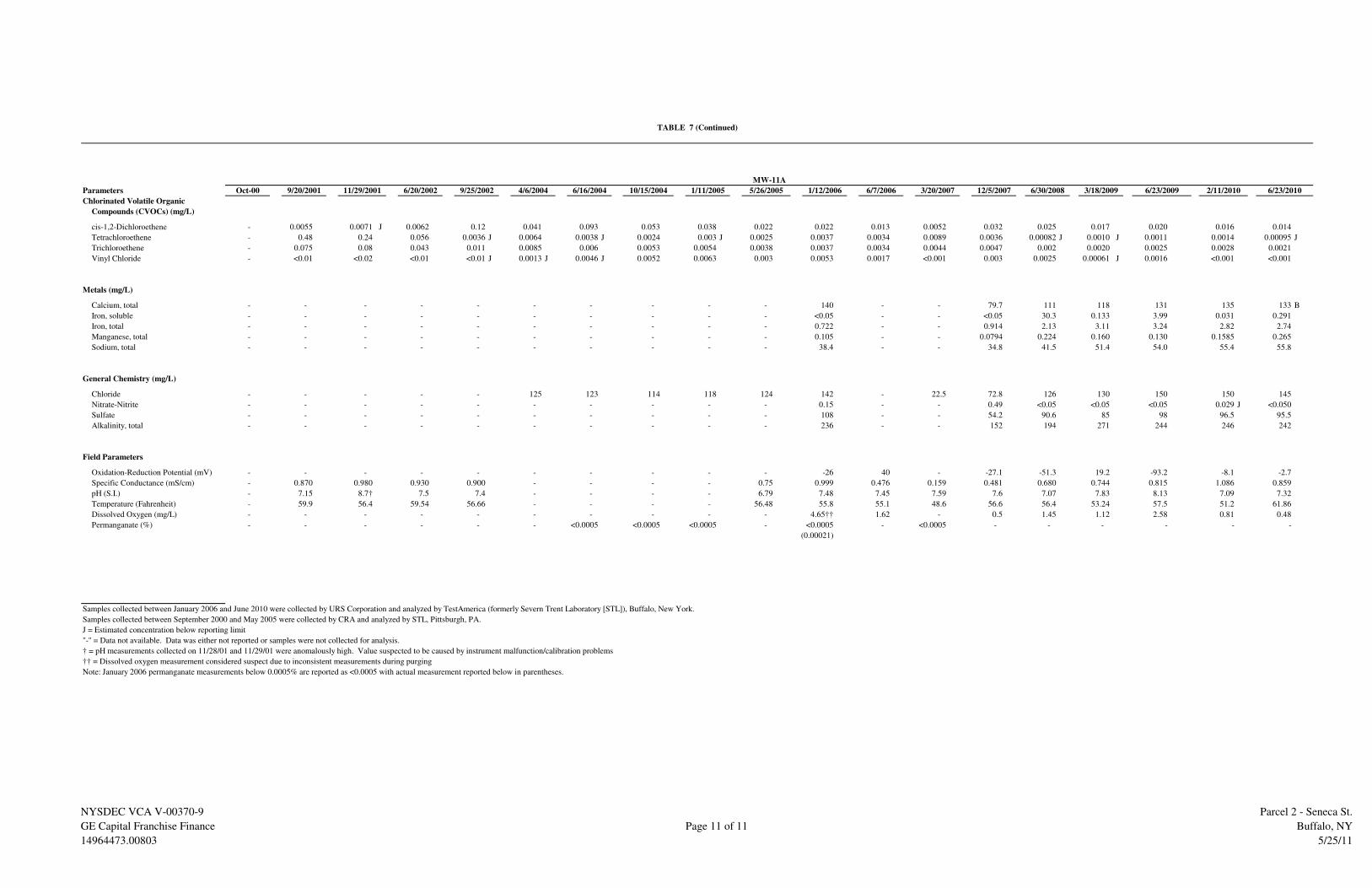
Parameters
Chlorinated Volatile Organic
Compounds (CVOCs) (mg/L)
cis-1,2-Dichloroethene - 0.0055 0.0071 J 0.0062 0.12 0.041 0.093 0.053 0.038 0.022 0.022 0.013 0.0052 0.032 0.025 0.017 0.020 0.016 0.014
Tetrachloroethene - 0.48 0.24 0.056 0.0036 J 0.0064 0.0038 J 0.0024 0.003 J 0.0025 0.0037 0.0034 0.0089 0.0036 0.00082 J 0.0010 J 0.0011 0.0014 0.00095 J
Trichloroethene - 0.075 0.08 0.043 0.011 0.0085 0.006 0.0053 0.0054 0.0038 0.0037 0.0034 0.0044 0.0047 0.002 0.0020 0.0025 0.0028 0.0021
Vinyl Chloride - <0.01 <0.02 <0.01 <0.01 J 0.0013 J 0.0046 J 0.0052 0.0063 0.003 0.0053 0.0017 <0.001 0.003 0.0025 0.00061 J 0.0016 <0.001 <0.001
Metals (mg/L)
Calcium, total - - - - - - - - - - 140 - - 79.7 111 118 131 135 133 B
Iron, soluble - - - - - - - - - - <0.05 - - <0.05 30.3 0.133 3.99 0.031 0.291
Iron, total - - - - - - - - - - 0.722 - - 0.914 2.13 3.11 3.24 2.82 2.74
Manganese, total - - - - - - - - - - 0.105 - - 0.0794 0.224 0.160 0.130 0.1585 0.265
Sodium, total - - - - - - - - - - 38.4 - - 34.8 41.5 51.4 54.0 55.4 55.8
General Chemistry (mg/L)
Chloride - - - - - 125 123 114 118 124 142 - 22.5 72.8 126 130 150 150 145
Nitrate-Nitrite - - - - - - - - - - 0.15 - - 0.49 <0.05 <0.05 <0.05 0.029 J <0.050
Sulfate - - - - - - - - - - 108 - - 54.2 90.6 85 98 96.5 95.5
Alkalinity, total - - - - - - - - - - 236 - - 152 194 271 244 246 242
Field Parameters
Oxidation-Reduction Potential (mV) - - - - - - - - - - -26 40 - -27.1 -51.3 19.2 -93.2 -8.1 -2.7
Specific Conductance (mS/cm) - 0.870 0.980 0.930 0.900 - - - - 0.75 0.999 0.476 0.159 0.481 0.680 0.744 0.815 1.086 0.859
pH (S.I.) - 7.15 8.7† 7.5 7.4 - - - - 6.79 7.48 7.45 7.59 7.6 7.07 7.83 8.13 7.09 7.32
Temperature (Fahrenheit) - 59.9 56.4 59.54 56.66 - - - - 56.48 55.8 55.1 48.6 56.6 56.4 53.24 57.5 51.2 61.86
Dissolved Oxygen (mg/L) - - - - - - - - - - 4.65†† 1.62 - 0.5 1.45 1.12 2.58 0.81 0.48
Permanganate (%) - - - - - - <0.0005 <0.0005 <0.0005 - <0.0005 - <0.0005 - - - - - -
(0.00021)
Samples collected between January 2006 and June 2010 were collected by URS Corporation and analyzed by TestAmerica (formerly Severn Trent Laboratory [STL]), Buffalo, New York.
Samples collected between September 2000 and May 2005 were collected by CRA and analyzed by STL, Pittsburgh, PA.
J = Estimated concentration below reporting limit
"-" = Data not available. Data was either not reported or samples were not collected for analysis.
† = pH measurements collected on 11/28/01 and 11/29/01 were anomalously high. Value suspected to be caused by instrument malfunction/calibration problems
†† = Dissolved oxygen measurement considered suspect due to inconsistent measurements during purging
Note: January 2006 permanganate measurements below 0.0005% are reported as <0.0005 with actual measurement reported below in parentheses.
6/23/20096/16/2004 5/26/2005 1/12/200610/15/2004 1/11/2005 12/5/2007Oct-00 3/18/20096/30/20089/20/2001 11/29/2001 6/20/2002 9/25/2002 6/7/2006 3/20/20074/6/2004 2/11/2010 6/23/2010
TABLE 7 (Continued)
MW-11A
NYSDEC VCA V-00370-9
GE Capital Franchise Finance
14964473.00803
Page 11 of 11
Parcel 2 - Seneca St.
Buffalo, NY
5/25/11

SCALE IN FEET
0 2000 4000
N
SITE
BASE MAP SOURCE: USGS 7 1/2 minute
topographic quadrangle map Buffalo SE, New
York 1965.
GE
F
F �
1
49
64
47
3.0
08
03
�
B
UF
FA
LO
, N
EW
YO
RK
�
S
ITE
M
GT
P
LA
N �
C
HE
CK
ED
B
Y
QuadrangleLocation
NY
GENERAL ELECTRICFRANCHISE FINANCE CORPORATION
FIGURE 1
SITE VICINITY MAP
2139 SENECA STREET
BUFFALO, NEW YORK
JOB NO. 14964473

APPROXIMATE SCALE IN FEET
0 50 100
N
GE
F
F �
1
49
64
47
3.0
08
03
�
B
UF
FA
LO
, N
EW
YO
RK
�
S
ITE
M
GT
P
LA
N �
C
HE
CK
ED
B
Y
PZ-A
SB-23SB-22
MW-3 SB-25 SB-3
SB-18
SB-15
SB-14
SB-4
SB-19
SB-13
SB-10
SB-24
MW-4
Kingston Place Seneca S
tre
et
SB-1/1A/1B
MW-4A
SB-17
SB-16A
SB-16
MW-2 SB-21
MW-5
SB-28
SB-29
SB-7
SB-6
MW-6
MW-1
SB-5
SB-9SB-26
SB-11
SB-27SB-12SB-8
93Kingston
Place
95Kingston
Place
97Kingston
Place99
KingstonPlace 101
KingstonPlace
2145 Seneca Street
2147 Seneca Street
2151 (2153) Seneca Street
2141 Seneca St.
2139 Seneca Street
2137SenecaStreet
CommercialResidential
Residential
Commercial
Commercial
Commercial
NOTE: Soil boring locations (SB Series) and historic
property addresses were extrapolated from Figures 2.2
and 2.3 of Final SIte Investigation Report and Feasibility
Study by CRA (March 2003).
GENERAL ELECTRICFRANCHISE FINANCE CORPORATION
FIGURE 2SITE LAYOUT MAP SHOWING PRE-REMEDIAL
SAMPLING LOCATIONS AND HISTORICADDRESSES
2139 SENECA STREETBUFFALO, NEW YORK
JOB NO. 14964473
TB-C
TB-B
2143SenecaStreet
LEGEND:
Property Boundary
Stormwater Drain
Pre-Remedial Monitoring Well
Pre-Remedial Monitoring Well
(No Soil Sample Collected)
Pre-Remedial Piezometer (URS, 2006)
Pre-Remedial Soil Boring (URS, 2006)
Pre-Remedial Soil Boring
Pre-Remedial Soil Boring
(No Soil Sample Collected)
Historic Building and Property Address93
KingstonPlace

GE
F
F �
1
49
64
47
3.0
08
03
�
B
UF
FA
LO
, N
EW
YO
RK
�
S
ITE
M
GT
P
LA
N �
C
HE
CK
ED
B
Y
APPROXIMATE SCALE IN FEET
0 50 100
N
MW-7
MW-7A
MW-12
PZ-2
MW-15
MW-9 MW-9APZ-1
PZ-3
MW-8 MW-8A
MW-10 MW-10A
MW-3
MW-15A
MW-14 MW-14A
MW-13A MW-13
MW-12A
Kingston Place Sen
eca S
treet
MW-4AMW-4
MW-2
MW-5
MW-6
MW-1
MW-11 MW-11A
IW-15
IW-10
IW-2S
PZ-A
LEGEND:
Property Boundary
Stormwater Drain
Shallow Monitoring Well Location
Deep Monitoring Well Location
Piezometer Location
Soil Boring Location
Injection Well Location
Cross Section LocationA A'
A
A'
TB-C
TB-B
GENERAL ELECTRICFRANCHISE FINANCE CORPORATION
FIGURE 3
SITE LAYOUT MAP WITH CROSS-SECTION
LOCATION
2139 SENECA STREET
BUFFALO, NEW YORKJOB NO. 14964473

GE
F
F �
1
49
64
47
3.0
08
03
�
B
UF
FA
LO
, N
EW
YO
RK
�
S
ITE
M
GT
P
LA
N �
C
HE
CK
ED
B
Y
NOTES:
� The depth and thickness of the strata indicated on the subsurface
section were obtained by interpolating between test borings. Information
on actual conditions exists only at the locations of the test borings and
it is possible that the conditions may vary from those indicated.
� No lithologic log available for IW-2S and IW-10.
� For location of cross section, see Figure 3.
SCALE IN FEET
VERTICAL EXAGGERATION = 2x
5
00 10
Silt- or Clay-Rich Fill Material
Sand- or Gravel-Rich Fill Material
Limestone Aggregate, Dense (2003 Excavation Backfill)
Clay with Trace Sand and/or Gravel, Moist to Wet
Silty Sand and/or Gravel
Silty Sand with Gravel, Moist to Wet
Clay with Gravel, Stiff, Dry
LEGEND:
A'SOUTHEAST
EL
EV
AT
ION
(F
EE
T, M
SL
)
595
590
585
580
575
570
565
560
ANORTHWEST
EL
EV
AT
ION
(F
EE
T, M
SL
)
595
590
585
580
575
570
565
560
MW
-9/M
W-9
A
MW
-2
TB
-C
TB
-B
MW
-11/M
W-1
1A
PZ
-A
MW
-4/M
W-4
A
ND
0.003
66.400102.154
ND
0.005
Clayey Gravel, Wet
Monitoring Well/Boring Location and Number
Soil Sample Interval
Well Screen Interval
Chlorinated Volatile Organic Compound (CVOC) Concentration in Soil (mg/kg)
Not Detected
MW-2
0.003
ND
IW-2
S
IW-1
0
0.009
0.006
GENERAL ELECTRICFRANCHISE FINANCE CORPORATION
FIGURE 4
CROSS-SECTION A - A'
2139 SENECA STREET
BUFFALO, NEW YORK
JOB NO. 14964473
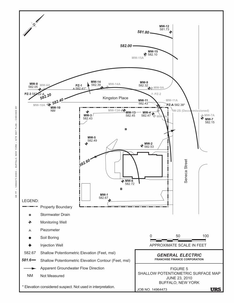
APPROXIMATE SCALE IN FEET
0 50 100
N
GE
F
F �
1
49
64
47
3.0
08
03
�
B
UF
FA
LO
, N
EW
YO
RK
�
S
ITE
M
GT
P
LA
N �
C
HE
CK
ED
B
Y
MW-7
582.15
MW-7A
MW-12
581.73
PZ-2
MW-15
582.10
MW-9
582.32MW-9A
PZ-1
582.41*
PZ-3 582.22
MW-8A
MW-15A
MW-14A
MW-13A
Kingston Place
Se
neca S
tre
et
MW-4A
MW-4
582.47
MW-2
582.53
MW-5
582.49
MW-6
582.72
MW-1
582.67
MW-11
582.43MW-11A
PZ-A 582.38*
* Elevation considered suspect. Not used in interpretation.
581.80
582.20
582.40
MW-13
582.45
MW-8
582.05
MW-10
NM
MW-10A
MW-14
582.39
MW-3
582.43
IW-2S (Decommissioned)
582.00
582.60
LEGEND:
Property Boundary
Stormwater Drain
Monitoring Well
Piezometer
Soil Boring
Injection Well
Shallow Potentiometric Elevation (Feet, msl)
Shallow Potentiometric Elevation Contour (Feet, msl)
Apparent Groundwater Flow Direction
Not Measured
581.6
582.67
NM
GENERAL ELECTRICFRANCHISE FINANCE CORPORATION
FIGURE 5
SHALLOW POTENTIOMETRIC SURFACE MAP
JUNE 23, 2010
BUFFALO, NEW YORK
JOB NO. 14964473
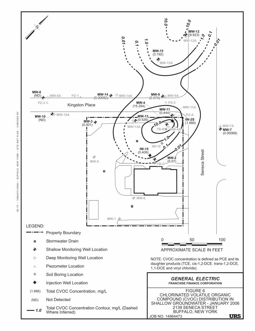
GE
F
F �
1
49
64
47
3.0
08
03
�
B
UF
FA
LO
, N
EW
YO
RK
�
S
ITE
M
GT
P
LA
N �
C
HE
CK
ED
B
Y
APPROXIMATE SCALE IN FEET
0 50 100
N
MW-7
(0.00068)
MW-7A
MW-12
(9.923)
PZ-2
MW-15
(3.192)
MW-9APZ-1
PZ-3
MW-8A
MW-10A
MW-15A
MW-14A
MW-13A
MW-10
(ND)
MW-8
(ND)
Kingston Place
Seneca
Str
eet
MW-4
(15.354)
MW-5
MW-6
MW-11
(0.444)PZ-A
TB-B
TB-C
LEGEND:
Property Boundary
Stormwater Drain
Shallow Monitoring Well Location
Deep Monitoring Well Location
Piezometer Location
Soil Boring Location
Injection Well Location
Total CVOC Concentration, mg/L
Not Detected
Total CVOC Concentration Contour, mg/L (DashedWhere Inferred)
MW-3
(0.001)
MW-13
(0.526)
MW-1
(1.666)
(ND)
1.0
MW-14
MW-12A
MW-9
(0.074)
NOTE: CVOC concentration is defined as PCE and its
daughter products (TCE, cis-1,2-DCE. trans-1,2-DCE,
1,1-DCE and vinyl chloride).
MW-2
(0.07)
MW-11A
1.0
10.0
0.1
IW-2S
(1.666)
MW-4A
IW-15
(0.409)0.0
1IW-10
0.0
1
0.1
1.0
10.0
10
.0
1.00.1
0.0
1
MW-14
(0.00092)
GENERAL ELECTRICFRANCHISE FINANCE CORPORATION
FIGURE 6CHLORINATED VOLATILE ORGANIC
COMPOUND (CVOC) DISTRIBUTION INSHALLOW GROUNDWATER - JANUARY 2006
2139 SENECA STREETBUFFALO, NEW YORK
JOB NO. 14964473

N
APPROXIMATE SCALE IN FEET
0 15 30
GE
F
F �
1
49
64
47
3.0
03
03
�
B
UF
FA
LO
, N
EW
YO
RK
�
R
EM
ED
IAT
IO 9
/07
�
C
HE
CK
ED
B
Y
MW-3
Kingston Place
Seneca S
treet
MW-4
MW-2
MW-5
MW-11MW-11A
MW-4A
MW-13A MW-13
GENERAL ELECTRICFRANCHISE FINANCE CORPORATION
FIGURE 7
EXTENT OF EXCAVATION AND POST
EXCAVATION SAMPLING LOCATIONS
2139 SENECA STREET, BUFFALO, NEW YORK
JOB NO. 14964473
Area A
Area B
Area C
Area D
Area E
Area F
Area G
Area H1
Area
H2
Area I
Area J
Area B2Area K1
Area K2
27
17
16
15
14 32
38 10
234
1
LEGEND:
Property Boundary
Stormwater Drain
Shallow MonitoringWell Location
Deep Monitoring WellLocation
Gas Line
Water Main
Storm Sewer Line
Sanitary Sewer Line
Electrical PVC Conduit(1� bgs)
Water Copper Line(4� bgs)
Excavation to 2' bgs
Excavation to 4' bgs
Excavation to 6' bgs
Excavation to 8' bgs
Excavation to 9' bgs
Excavation to 10' bgs
Post-ExcavationBottom SampleLocation (DRS-SeriesSample)
Post-ExcavationSidewall SampleLocation (DRS-SeriesSample)
Excavation AreaLocation
27
17
Area
A
19/3018/3142/43
40/41
22
2021
28
29
23
24
13
26/36
379
8
44/45
347
48
47
33
35
5
6
25
NOTE: Excavation sample analytical results arepresented in Table 6 of the Site Managment Plan.

IW-18S/D
IW-4S/D
IW-7S/D
N
APPROXIMATE SCALE IN FEET
0 15 30
GE
F
F �
1
49
64
47
3.0
03
03
�
B
UF
FA
LO
, N
EW
YO
RK
�
R
EM
ED
IAT
IO 9
/07
�
C
HE
CK
ED
B
Y
MW-3
Property Boundary
Stormwater Drain
Shallow Monitoring WellLocation
Deep Monitoring WellLocation
Piezometer Location
Injection Well Location
Gravity Feeding Line toInjection Well
Gravity Feeding Gallery(10' bgs)
Service Box
Gas Line
Water Main
Storm Sewer Line
Sanitary Sewer Line
Electrical PVC Conduit(1� bgs)
Water Copper Line(4� bgs)
LEGEND:
* IW-2S was decommissionedNovember 2009
Kingston Place
Seneca S
treet
MW-4
MW-2
MW-5
MW-11MW-11A
IW-15S/D
IW-2S*
PZ-A
IW-3S/D
IW-8S/D
IW-17S/D
IW-16S/D
IW-1S/D
IW-6S/D
MW-4A
MW-13A MW-13
2" Riser IW-11
IW-2D
IW-10
IW-12
IW-13 IW-14
IW-9S/D
IW-5S/D
GENERAL ELECTRICFRANCHISE FINANCE CORPORATION
FIGURE 8
IN-SITU CHEMICAL OXIDATION (ISCO)
SYSTEM LOCATION MAP
2139 SENECA STREET, BUFFALO, NEW YORK
JOB NO. 14964473

N
APPROXIMATE SCALE IN FEET
0 15 30
GE
F
F �
1
49
64
47
3.0
08
03
�
B
UF
FA
LO
, N
EW
YO
RK
�
S
ITE
M
GT
P
LA
N �
C
HE
CK
ED
B
Y
NOTE: CVOC concentration is defined as PCE and its daughter
products (TCE, cis-1,2-DCE. trans-1,2-DCE, 1,1-DCE and vinyl
chloride). CVOC concentrations from MW-4A and MW-11A were not
used in the contour interpretation.
LEGEND:
Property Boundary
Stormwater Drain
Shallow MonitoringWell Location
Deep Monitoring WellLocation
Shallow Piezometer/Injection Well Location
HRC/ZVI DoubleInjection Point (80 lbsZVI/60 lbs HRC perInjection
HRC/ZVI DoubleInjection Point (55 lbsZVI/40 lbs HRC perInjection)
Gas Line
Water Main
Storm Sewer Line
Sanitary Sewer Line
Excavation Limits
Pre-Remedial TotalShallow CVOCConcentration Contour,mg/L (Dashed WhereInferred) MeasuredMarch 20, 2007
1.0
MW-3
B-12
IW-2S
A-8
Kingston Place
Seneca S
treet
MW-4
MW-2
MW-5
MW-11
MW-11A
PZ-A
MW-4A
MW-13A
MW-13
B-9
B-8
B-10 B-11
B-13
B-16 B-15
B-17
B-7
B-6B-4
B-2
B-3 B-5 A-5
A-6
A-7
A-12A-13
A-14
A-15
A-9
A-10
A-1
A-2A-3A-4
A-11
B-1
B-14
10
1.0
0.1
0.1
1.0
GENERAL ELECTRICFRANCHISE FINANCE CORPORATION
FIGURE 9
SEPTEMBER 2007 INJECTION EVENT
2139 SENECA STREET, BUFFALO, NEW YORK
JOB NO. 14964473
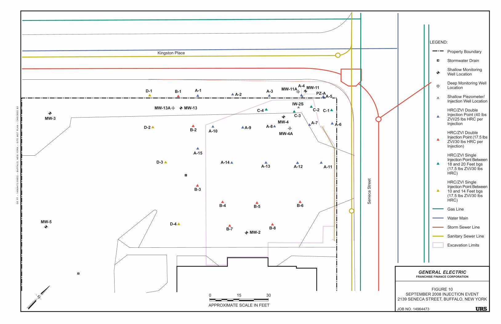
N
APPROXIMATE SCALE IN FEET
0 15 30
GE
F
F �
1
49
64
47
3.0
08
03
�
B
UF
FA
LO
, N
EW
YO
RK
�
S
ITE
M
GT
P
LA
N �
C
HE
CK
ED
B
Y
LEGEND:
Property Boundary
Stormwater Drain
Shallow MonitoringWell Location
Deep Monitoring WellLocation
Shallow Piezometer/Injection Well Location
HRC/ZVI DoubleInjection Point (40 lbsZVI/25 lbs HRC perInjection
HRC/ZVI DoubleInjection Point (17.5 lbsZVI/30 lbs HRC perInjection)
HRC/ZVI SingleInjection Point Between18 and 20 Feet bgs(17.5 lbs ZVI/30 lbsHRC)
HRC/ZVI SingleInjection Point Between10 and 14 Feet bgs(17.5 lbs ZVI/30 lbsHRC)
Gas Line
Water Main
Storm Sewer Line
Sanitary Sewer Line
Excavation Limits
MW-3
IW-2S
Kingston Place
Seneca S
treet
MW-4
MW-2
MW-5
MW-11MW-11A
PZ-A
MW-4A
MW-13A MW-13
D-1
D-2
D-3
D-4
B-3
B-4
A-15
B-2 A-10
B-1 A-1
B-6B-5
A-14
A-13 A-12 A-11
A-6A-7
A-8A-9
A-2A-3
A-4
A-5
C-1C-2C-4
C-3
B-8B-7
GENERAL ELECTRICFRANCHISE FINANCE CORPORATION
FIGURE 10
SEPTEMBER 2008 INJECTION EVENT
2139 SENECA STREET, BUFFALO, NEW YORK
JOB NO. 14964473

N
APPROXIMATE SCALE IN FEET
0 15 30
GE
F
F �
1
49
64
47
3.0
08
03
�
B
UF
FA
LO
, N
EW
YO
RK
�
S
ITE
M
GT
P
LA
N �
C
HE
CK
ED
B
Y
NOTE: CVOC concentration is defined as PCE and its daughter
products (TCE, cis-1,2-DCE. trans-1,2-DCE, 1,1-DCE and vinyl
chloride). CVOC concentrations from MW-4A and MW-11A were not
used in the contour interpretation.
MW-3
IW-2SA-4SD
Kingston Place
Seneca S
treet
MW-4
MW-2
MW-5
MW-11
MW-11A
MW-4A
MW-13A
MW-13
B-1SD
A-1S
B-2SD B-3SD
B-4SDB-5SD
B-6SD
A-2SD
A-3SDD
A-5SD
A-6SDA-7SD
PZ-A
LEGEND:
Property Boundary
Stormwater Drain
Shallow MonitoringWell Location
Deep Monitoring WellLocation
Shallow Piezometer/Injection Well Location
EHC/ZVI SingleShallow Injection Point(42.5 lbs ZVI/57 lbsEHC)
EHC/ZVI DoubleInjection Point (42.5 lbsZVI/57 lbs EHC perInjection)
EHC/ZVI DoubleInjection Point (29 lbsZVI/33 lbs EHC perInjection)
EHC/ZVI TripleInjection Point (42.5 lbsZVI/57 lbs EHC perInjection)
Gas Line
Water Main
Storm Sewer Line
Sanitary Sewer Line
Excavation Limits
A-2SD
B-1SD
A-1S
A-3SDD
GENERAL ELECTRICFRANCHISE FINANCE CORPORATION
FIGURE 11
NOVEMBER 2009 INJECTION EVENT
2139 SENECA STREET, BUFFALO, NEW YORK
JOB NO. 14964473

APPROXIMATE SCALE IN FEET
0 50 100
N
GE
F
F �
1
49
64
47
3.0
08
03
�
B
UF
FA
LO
, N
EW
YO
RK
�
S
ITE
M
AN
AG
EM
EN
T P
LA
N �
C
HE
CK
ED
B
Y
MW-12
PZ-2
MW-15
MW-9APZ-1
PZ-3
MW-8 MW-8A
MW-10A
MW-15A
MW-10
MW-9
Kingston Place
Seneca S
treet
MW-5
MW-1
MW-12A
NOTES:
- Total CVOC concentration is defined as PCE and its
breakdown products (TCE, cis-1,2-DCE. trans-1,2-DCE,
1,1-DCE and vinyl chloride).
- Several elevated concentrations required a dilution.
MW-13A
MW-14AMW-14
Deep Monitoring Well Location
Piezometer Location
Injection Well Location
LEGEND:
Property Boundary
Stormwater Drain
Shallow Monitoring Well Location
KEY TO ANALYTICAL DATA
NOTE:
1. Pre-Injection results (January 2006, June 2006,
and March 2007) are shown in Black.
2. Post-Phase I Injection results (December 2007
and June 2008) are shown in Blue.
3. Post-Phase II Injection results (March, June
and August 2009) are shown in Red.
4. Post-Phase III Injection results (February, June
and August 2010) are shown in Green.
PCE
TCE
cDCE
VC
0.016
<0.001
J
NA
Dec 07
Tetrachloroethene
Trichloroethene
cis-1,2-Dichloroethene
Vinyl Chloride
Constituent Concentration in mg/L
Not Detected at Its Reporting Limit
Estimated Concentration
Not Analyzed
Month and Year Sample Collected
PCE
TCE
cDCE
VC
Total CVOCs
MW-13
Dec 07
<0.01
<0.01
1
0.29
1.29
Mar 07
1.2
0.066
0.028
<0.008
1.294
May 05
0.56
0.044J
0.017J
<0.05
0.621
Jan 05
0.13
0.0096
0.0039J
<0.005
0.144
Jun 06
0.790
0.048
0.023
<0.001
0.861
Jan 06
0.47
0.039
0.017
<0.001
0.526
Jun 08
<0.001
0.0047
0.018
0.02
0.038
Mar 09
<0.001
<0.001
0.031
0.007
0.038
Jun 09
<0.001
<0.001
0.0023
0.002
0.0049
Jun 10
<0.001
<0.001
0.0055
0.049
0.0143
GENERAL ELECTRICFRANCHISE FINANCE CORPORATION
FIGURE 12
CHLORINATED VOLATILE ORGANIC
COMPOUND (CVOC) CONCENTRATIONS IN
SHALLOW GROUNDWATER
JANUARY 2005 TO AUGUST 2010
JOB NO. 14964473
MW-7A
Feb 10
<0.001
<0.001
0.019
0.029
0.0486
PCE
TCE
cDCE
VC
Total CVOCs
IW-2S
Dec 07
0.042
0.037
9.3
9.9
19.279
Jun 06
6.8
0.56
0.26
0.003
7.623
Jan 06
7.3
2.1
1.2
0.05
10.65
Jun 08
0.0062
0.0073
7.1
8.2
15.3135
Mar 09
0.0016
0.001J
0.018
0.0028J
0.023
Jun 09
NA
NA
NA
NA
NA
Jun 10
NA
NA
NA
NA
NA
Feb 10
NA
NA
NA
NA
NA
PCE
TCE
cDCE
VC
Total CVOCs
MW-3
Jan 06
0.00088 J
<0.001
<0.001
<0.001
0.00088
Jun 08
<0.001
<0.001
<0.001
<0.001
<0.001
Mar 09
<0.001
<0.001
0.0012
0.0017
0.0029
Jun 09
<0.001
<0.001
0.0024
0.00075J
0.0032
Jun 10
<0.001
<0.001
<0.001
<0.001
<0.001
Feb 10
NA
NA
NA
NA
NA
Dec 07
NA
NA
NA
NA
NA
PCE
TCE
cDCE
VC
Total CVOCs
MW-11
Dec 07
0.001J
0.003J
0.54
0.88
1.424
Mar 07
0.49
0.044
0.023
<0.001
0.557
May 05
3.4
0.64
0.19J
<0.2
4.23
Jan 05
0.15
0.021
0.01
<0.005
0.181
Jun 06
0.008
0.002
0.002
<0.001
0.012
Jan 06
0.39
0.038
0.016
<0.001
0.444
Jun 08
<0.001
0.0011
0.58
0.84
1.4211
Mar 09
<0.001
0.001J
0.330
0.590
0.921
Jun 09
<0.001
<0.001
0.027
0.070
0.097
Jun 10
<0.001
<0.001
0.013
0.049
0.062
Feb 10
<0.001
<0.001
0.0024
0.016
0.0184
PCE
TCE
cDCE
VC
Total CVOCs
MW-11A
Dec 07
0.004
0.005
0.032
0.003
0.044
Mar 07
0.009
0.004
0.005
<0.001
0.018
May 05
0.0025
0.0038
0.022
0.003
0.031
Jan 05
0.003J
0.0054
0.038
0.0063
0.053
Jun 06
0.003
0.003
0.013
0.002
0.021
Jan 06
0.004
0.004
0.022
0.005
0.035
Jun 08
0.00082J
0.002
0.025
0.0025
0.03032
Mar 09
0.001J
0.002
0.017
0.00061J
0.021
Jun 09
0.0011
0.0025
0.020
0.0016
0.0252
Jun 10
0.00095J
0.0021
0.014
<0.001
0.01945
Feb 10
0.0014
0.0028
0.016
<0.001
0.0202
PCE
TCE
cDCE
VC
Total CVOCs
MW-6
Dec 07
<0.001
<0.001
<0.001
<0.001
<0.001
Jun 08
<0.001
<0.001
<0.001
<0.001
<0.001
Mar 09
<0.001
<0.001
0.00063J
0.00068J
0.001
Jun 09
<0.001
<0.001
0.005
0.0024
0.0074
Feb 10
<0.001
<0.001
<0.001
<0.001
<0.001
Jun 10
<0.001
<0.001
<0.001
<0.001
<0.001
PCE
TCE
cDCE
VC
Total CVOCs
MW-2
Dec 07
<0.001
<0.001
0.085
0.053
0.138
Mar 07
0.062
0.028
0.14
0.002
0.232
May 05
0.0046
0.0043
0.0052
<0.001
0.014
Jan 05
0.097
0.061
0.14
0.0018J
0.3
Jun 06
0.073
0.037
0.074
0.002
0.186
Jan 06
0.025
0.018
0.027
<0.001
0.07
Jun 08
<0.001
<0.001
0.023
0.024
0.047
Mar 09
<0.001
0.00046J
0.039
0.024
0.063
Jun 09
<0.001
<0.001
0.760
0.720
1.4882
Aug 09
<0.001
<0.001
0.300
0.250
0.5541
Feb 10
<0.001
0.0025
0.190
0.200
0.3946
Jun 10
<0.001
<0.001
0.011
0.017
0.028
PCE
TCE
cDCE
VC
Total CVOCs
PZ-A
Dec 07
0.006
0.01
4.2
3
7.216
Jun 06
1.5
0.24
0.21
<0.001
1.95
Jun 08
0.015
0.0076
1.4
0.77
2.1926
Mar 09
<0.010
<0.010
0.420
0.690
1.110
Jun 09
<0.001
0.00077J
0.150
0.200
0.3512
Feb 10
<0.001
0.00088J
0.043
0.093
0.1369
Jun 10
0.00053J
0.00076J
0.065
0.15
0.21629
PCE
TCE
cDCE
VC
Total CVOCs
MW-7
Dec 07
<0.001
<0.001
<0.001
<0.001
<0.001
Jan 06
0.001J
<0.001
<0.001
<0.001
0.001
May 05
<0.001
<0.001
<0.001
<0.001
<0.001
Jan 05
<0.005
<0.005
<0.005
<0.005
<0.005
Jun 08
<0.001
<0.001
<0.001
<0.001
<0.001
Mar 09
<0.001
<0.001
0.00033J
<0.001
0.0003
Jun 09
<0.001
<0.001
0.00091J
<0.001
0.0009
Feb 10
<0.001
<0.001
0.00056J
<0.001
0.00056
Jun 10
<0.001
<0.001
<0.001
<0.001
<0.001
PCE
TCE
cDCE
VC
Total CVOCs
MW-4A
Dec 07
<0.001
<0.001
0.016
0.013
0.029
Mar 07
0.028
0.012
0.02
0.009
0.069
Jun 06
0.005
0.005
0.024
0.014
0.048
Jan 06
0.001J
0.003
0.015
0.019
0.038
May 05
0.00018J
0.0063J
0.017
0.019
0.042
Jan 05
<0.005
0.0015J
0.028
0.038
0.068
Jun 08
<0.001
<0.001
0.0098
0.015
0.0248
Mar 09
<0.001
<0.001
0.064
0.017
0.087
Jun 09
<0.001
<0.001
0.0089
0.0053
0.0142
Feb 10
<0.001
<0.001
0.0068
0.008
0.0148
Jun 10
<0.001
<0.001
0.0057
0.014
0.0197
PCE
TCE
cDCE
VC
Total CVOCs
MW-4
Dec 07
<0.001
0.001J
2.4
1.4
3.801
Mar 07
13
3.8
2.2
<0.1
19
May 05
9.7
1.7
0.33J
<0.5
11.73
Jan 05
7.1
2.8
1.2
<0.25
11.1
Jun 06
7.6
3
0.36
0.006J
10.975
Jan 06
12
2.8
0.54
0.008
15.354
Jun 08
0.00047J
0.0014
0.91
0.78
1.69187
Mar 09
0.0014
0.0045
13
3.3
16.306
Jun 09
0.00051J
0.00085J
3.5
1.7
5.2161
Feb 10
0.0014
0.00099J
0.94
1.0
1.9455
Jun 10
0.0022
0.0019
3.5
2.8
6.3115
Aug 10
<0.025
<0.025
1.3
1.5
2.8

APPROXIMATE SCALE IN FEET
0 20 40
N
GE FF � 14964473.00503 � BUFFALO, NEW YORK � SITE MGT PLAN � CHECKED BY
LEGEND:
Property Boundary
Stormwater Drain
Soil Sample Location with Results
Below Track 1 (Unrestricted) Soil
Cleanup Objectives (SCOs)
Soil Sample Location with Results
Between Track 1 (Unrestricted) and
Track 2 (Commercial Land-Use) SCOs
Depth in Feet Below Ground Surface
(BGS)
SB-23 (11-12)
SB-22 (11-12)
MW-3 (0-2, 4-6)
SB-25 (8-10) SB-3 (12-16)
SB-14 (5-7)
SB-4 (12-16)
SB-24 (8-10)
Kingston Place
Seneca S
treet
SB-1B (8-12)
SB-21 (6-8)
MW-5 (1-3)
SB-28 (6-8)
SB-29 (8-10)
MW-1 (3-5)
TB-C (11-12, 27-28)
DRS-35 (9)*
DRS-26 (8)*
DRS-36 (8)*
DRS-34 (0-8)DRS-7 (0-8)
DRS-48 (0-8)
DRS-47 (0-9)
DRS-33 (0-9)
DRS-2 (9-10)*DRS-3 (9-10)*
DRS-1 (0-10)
DRS-45 (0-8)DRS-44 (0-8)
DRS-19 (6-10)*DRS-18 (6-10)*
DRS-41 (0-9)
DRS-43 (6-9)*DRS-42 (6-9)*
DRS-20 (0-2)
DRS-28 (2)*
DRS-29 (4)*
DRS-24 (0-4)
(8)
DRS-25 (9)*DRS-37 (9)*
DRS-27 (9)*
DRS-4 (9-10)*
DRS-13 (9-10)*DRS-40 (0-9)
DRS-23 (4-6)**
DRS-21 (2-4)*
DRS-22 (2-6)**
DRS-17 (9)**
DRS-15 (9)**
DRS-14 (9)**
DRS-32 (9)**
DRS-9
(9)**
DRS-16 (9)**
DRS-5 (9)**
**- This initial Stage Wall Sample
(October 21-23, 2003) likely represents soil
that was later removed during the
second stage excavation (October 27-
November 3, 2003 and backfilled with
clean fill in 2003.
*- All soil above this depth was excaved and
backfilled with clean fill in 2003.
DRS-38 (9)*
DRS-8 (8-9)*
GENERAL ELECTRICFRANCHISE FINANCE CORPORATION
FIGURE 13POST-REMEDIAL ACTION SOIL SAMPLELOCATIONS - CHLORINATED VOLATILE
ORGANIC COMPOUNDS (CVOCs)2139 SENECA STREETBUFFALO, NEW YORK
JOB NO. 14964473
PZ-A (8-9, 10-11, 18-19)
TB-B (18-19, 26-27)
DRS-10 (8-9)*
DRS-6 (8-9)*
NOTE: Excavation sample analytical results arepresented in Table 6 of the Site Managment Plan.

APPROXIMATE SCALE IN FEET
0 20 40
N
GE FF � 14964473.00503 � BUFFALO, NEW YORK � SITE MGT PLAN � CHECKED BY
LEGEND:
Property Boundary
Stormwater Drain
Soil Sample Location with Results
Below Track 1 (Unrestricted) Soil
Cleanup Objectives (SCOs)
Soil Sample Location with Results
Above Track 2 (Commercial Land-Use)
SCOs
Depth in Feet Below Ground Surface
(BGS)
MW-3 (0-2, 4-6)
SB-14 (5-7)
Kingston Place
Seneca S
treet
MW-5 (1-3)
MW-1 (3-5)
DRS-35 (9)*
(8)* DRS-26DRS-36 (8)*
DRS-34 (0-8)DRS-7
(0-8)
DRS-48 (0-8)
DRS-47 (0-9)
DRS-33 (0-9)
DRS-2 (9-10)*DRS-3
(9-10)*
DRS-1
(0-10)
DRS-45 (0-8)DRS-44 (0-8)
DRS-19
(6-10)*
DRS-18
(6-10)*
DRS-41
(0-9)
DRS-43
(6-9)*(12-16)* DRS-42
(0-10) DRS-20
DRS-28
(10)*
DRS-29 (4)*
DRS-24 (0-4)
(8)
DRS-25 (9)*
(9)* DRS-37
(9)* DRS-27
DRS-4
(9-10)*
DRS-13 (9-10)*
DRS-30
(6-10)*
DRS-31
(6-10)*
(0-9) DRS-40
DRS-21 (2-4)*
DRS-17 (9)**
DRS-32 (9)*
DRS-38
(9)*
(8-10) SB-24
DRS-8
(8-9)*
SB-12 (7-9)
SB-7 (8-12)(4-8) SB-8
SB-6 (8-12)
(10-12) SB-27(7-9) SB-11
(0-4) SB-9
(10-12) SB-26
(7-9) SB-13
(8-12) SB-10
DRS-23 (4-6)**DRS-22 (2-6)**
DRS-15 (9)**
DRS-14 (9)**
DRS-9
(9)**
DRS-16 (9)**
DRS-5 (9)**
**- This initial Stage Wall Sample
(October 21-23, 2003) likely represents soil
that was later removed during the
second stage excavation (October 27-
November 3, 2003 and backfilled with
clean fill in 2003.
*- All soil above this depth was excaved and
backfilled with clean fill in 2003.
GENERAL ELECTRICFRANCHISE FINANCE CORPORATION
FIGURE 14POST-REMEDIAL ACTION SOIL SAMPLELOCATIONS - POLYNUCLEAR AROMATIC
HYDROCARBONS (PAHs)2139 SENECA STREETBUFFALO, NEW YORK
JOB NO. 14964473
DRS-10 (8-9)*
DRS-6 (8-9)*
NOTE: Excavation sample analytical results arepresented in Table 6 of the Site Managment Plan.
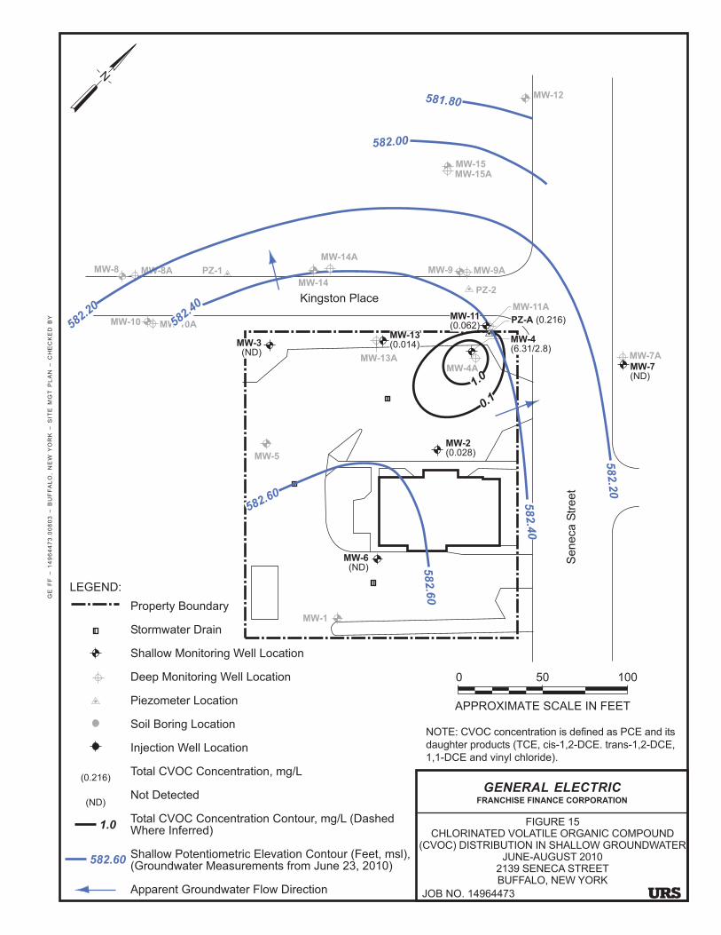
GE
F
F �
1
49
64
47
3.0
08
03
�
B
UF
FA
LO
, N
EW
YO
RK
�
S
ITE
M
GT
P
LA
N �
C
HE
CK
ED
B
Y
APPROXIMATE SCALE IN FEET
0 50 100
N
MW-7
(ND)
MW-7A
MW-12
PZ-2
MW-15
MW-9APZ-1MW-8A
MW-10A
MW-15A
MW-14A
MW-13A
MW-10
MW-8
Kingston Place
Seneca S
treet
MW-4
(6.31/2.8)
MW-5
MW-11
(0.062)PZ-A (0.216)
MW-3
(ND)
MW-13
(0.014)
MW-1
MW-14
MW-9
NOTE: CVOC concentration is defined as PCE and its
daughter products (TCE, cis-1,2-DCE. trans-1,2-DCE,
1,1-DCE and vinyl chloride).
MW-2
(0.028)
MW-11A
MW-4A
MW-6
(ND)
GENERAL ELECTRICFRANCHISE FINANCE CORPORATION
FIGURE 15CHLORINATED VOLATILE ORGANIC COMPOUND
(CVOC) DISTRIBUTION IN SHALLOW GROUNDWATERJUNE-AUGUST 2010
2139 SENECA STREETBUFFALO, NEW YORK
JOB NO. 14964473
1.0
0.1
582.20
582.40
582.00
581.80582.2
0
582.4
0
582.6
0
582.60
LEGEND:
Property Boundary
Stormwater Drain
Shallow Monitoring Well Location
Deep Monitoring Well Location
Piezometer Location
Soil Boring Location
Injection Well Location
Total CVOC Concentration, mg/L
Not Detected
Total CVOC Concentration Contour, mg/L (DashedWhere Inferred)
Shallow Potentiometric Elevation Contour (Feet, msl),(Groundwater Measurements from June 23, 2010)
Apparent Groundwater Flow Direction
(0.216)
(ND)
582.60
1.0

GE
F
F �
1
49
64
47
3.0
08
03
�
B
UF
FA
LO
, N
EW
YO
RK
�
S
ITE
M
GT
P
LA
N �
C
HE
CK
ED
B
Y
APPROXIMATE SCALE IN FEET
0 50 100
N
LEGEND:
Property Boundary
Stormwater Drain
Shallow Monitoring Well To Be Sampled
Deep Monitoring Well To Be Sampled
Piezometer To Be Sampled
Shallow Monitoring Well To Be Decommissioned
Deep Monitoring Well To Be Decommissioned
Shallow Potentiometric Elevation Contour (Feet, msl),(Groundwater Measurements from June 23, 2010)
Apparent Groundwater Flow Direction
MW-7
MW-7A
MW-12
PZ-2
MW-15
MW-9APZ-1MW-8A
MW-10A
MW-15A
MW-14A
MW-13A
MW-10
MW-8
Kingston Place
Seneca S
treet
MW-4
MW-5
MW-11 PZ-A
MW-3MW-13
MW-1
MW-14
MW-9
NOTE: CVOC concentration is defined as PCE and its
daughter products (TCE, cis-1,2-DCE. trans-1,2-DCE,
1,1-DCE and vinyl chloride).
MW-2
MW-11A
MW-4A
MW-6
GENERAL ELECTRICFRANCHISE FINANCE CORPORATION
FIGURE 16
PLANNED GROUNDWATER MONITORING
SYSTEM
2139 SENECA STREET
BUFFALO, NEW YORKJOB NO. 14964473
582.20
582.40
582.00
581.80582.2
0
582.4
0
582.6
0
582.60
582.60

APPENDIX A
VOLUNTARY CLEANUP AGREEMENT


APPENDIX B
DECLARATION OF COVENANTS AND RESTRICTIONS(INCLUDING METES AND BOUNDS)


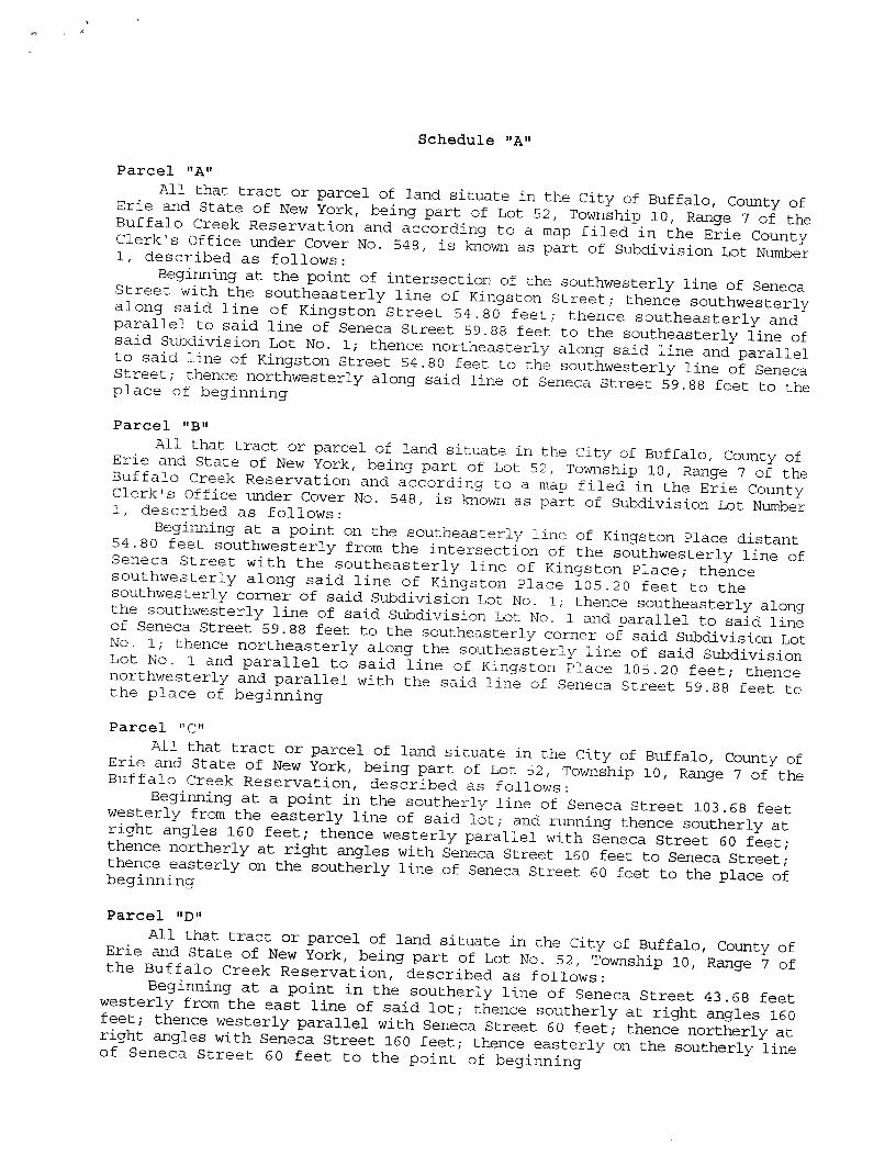


APPENDIX C
EXCAVATION WORK PLAN(INCLUDING COMMUNITY AIR MONITORING PLAN)

CONTENTS
SECTION PAGE
APPENDIX C – EXCAVATION WORK PLAN (EWP)...................................................................... C-1C-1 PURPOSE................................................................................................................ C-1C-2 SOIL SCREENING METHODS .............................................................................. C-2C-3 STOCKPILE METHODS ........................................................................................ C-3C-4 MATERIALS EXCAVATION AND LOAD OUT ................................................... C-4C-5 MATERIALS TRANSPORT OFF-SITE .................................................................. C-4C-6 MATERIALS DISPOSAL OFF-SITE ...................................................................... C-5C-7 MATERIALS REUSE ON-SITE.............................................................................. C-6C-8 FLUIDS MANAGEMENT....................................................................................... C-6C-9 COVER SYSTEM RESTORATION ........................................................................ C-7C-10 BACKFILL FROM OFF-SITE SOURCES............................................................... C-7C-11 STORMWATER POLLUTION PREVENTION....................................................... C-8C-12 CONTINGENCY PLAN.......................................................................................... C-9C-13 COMMUNITY AIR MONITORING PLAN............................................................. C-10
C-13.1 Vapor Emission Response Plan .................................................................. C-10C-13.2 Major Vapor Emission Response Plan ........................................................ C-11
C-14 ODOR CONTROL PLAN........................................................................................ C-12C-15 DUST CONTROL PLAN......................................................................................... C-13C-16 OTHER NUISANCES ............................................................................................. C-13
TABLES TO BE PREPARED IN THE ADDENDUM FOR THE EXCAVATION WORK PLAN(follow text)
Number
1 CHEMICAL CRITERIA (BASED ON TABLE 5 FROM THE SITE MANAGEMENT PLAN)2 GROUNDWATER AND SOIL QUALITY STANDARDS (BASED ON TABLE 5 FROM THE
SITE MANAGEMENT PLAN)
FIGURES FROM THE SITE MANAGEMENT PLAN(follow tables)
Number
7 EXTENT OF EXCAVATION AND POST EXCAVATION SAMPLING LOCATIONS13 POST-REMEDIAL ACTION SOIL SAMPLE LOCATIONS – CHLORINATED VOLATILE
ORGANIC COMPOUNDS (CVOCS)14 POST-REMEDIAL ACTION SOIL SAMPLE LOCATIONS – POLYNUCLEAR AROMATIC
HYDROCARBONS (PAHS)
APPENDICES(follow figures)
Appendix
A CONTRACTOR’S HEALTH AND SAFETY PLAN (TO BE PREPARED BASED ON THETEMPLATE PROVIDED IN APPENDIX D OF THE SITE MANAGEMENT PLAN)
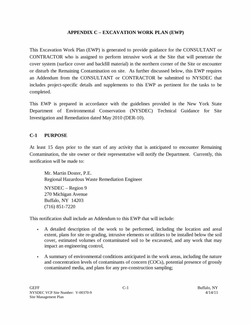
GEFF C-1 Buffalo, NYNYSDEC VCP Site Number: V-00370-9 4/14/11Site Management Plan
APPENDIX C – EXCAVATION WORK PLAN (EWP)
This Excavation Work Plan (EWP) is generated to provide guidance for the CONSULTANT or
CONTRACTOR who is assigned to perform intrusive work at the Site that will penetrate the
cover system (surface cover and backfill material) in the northern corner of the Site or encounter
or disturb the Remaining Contamination on site. As further discussed below, this EWP requires
an Addendum from the CONSULTANT or CONTRACTOR be submitted to NYSDEC that
includes project-specific details and supplements to this EWP as pertinent for the tasks to be
completed.
This EWP is prepared in accordance with the guidelines provided in the New York State
Department of Environmental Conservation (NYSDEC) Technical Guidance for Site
Investigation and Remediation dated May 2010 (DER-10).
C-1 PURPOSE
At least 15 days prior to the start of any activity that is anticipated to encounter Remaining
Contamination, the site owner or their representative will notify the Department. Currently, this
notification will be made to:
Mr. Martin Doster, P.E.
Regional Hazardous Waste Remediation Engineer
NYSDEC – Region 9
270 Michigan Avenue
Buffalo, NY 14203
(716) 851-7220
This notification shall include an Addendum to this EWP that will include:
A detailed description of the work to be performed, including the location and arealextent, plans for site re-grading, intrusive elements or utilities to be installed below the soilcover, estimated volumes of contaminated soil to be excavated, and any work that mayimpact an engineering control,
A summary of environmental conditions anticipated in the work areas, including the natureand concentration levels of contaminants of concern (COCs), potential presence of grosslycontaminated media, and plans for any pre-construction sampling;

GEFF C-2 Buffalo, NYNYSDEC VCP Site Number: V-00370-9 4/14/11Site Management Plan
A schedule for the work, detailing the start and completion of all intrusive work,
A summary of the applicable components of this EWP. The addendum will define thescope of work (i.e., shallow excavation above the water table with immediate disposal,deeper excavation requiring fluid management and/or stockpiling soil on site) and identifythe applicable components of an EWP for this scope.
A statement that the work will be performed in compliance with this EWP and 29 Code ofFederal Regulations (CFR) 1910.120,
A copy of the contractor’s health and safety plan (HASP), in electronic format, (a HASPtemplate is provided in Appendix D of this document to provide site-specific informationthat will aid the contractor in developing their own HASP),
Identification of disposal facilities for potential waste streams,
Identification of sources of any anticipated backfill, along with all required chemicaltesting results.
C-2 SOIL SCREENING METHODS
Previous site investigations have identified chlorinated volatile organic compounds (CVOCs) and
polynuclear aromatic hydrocarbons (PAHS) in the soil at various soil samples across the site.
Figures 13 and 14 in the Site Management Plan (SMP) illustrate the soil sample locations and
their designation regarding whether they contain constituents above or below unrestricted soil
cleanup objectives as of November 2010. Detailed listing of the specific CVOC and PAH
constituents and their respective concentrations can be found in Tables 2 and 6 of the SMP.
These figures only indicate the results of the soil samples collected and interpretation of impact is
limited to only the boring locations. During the development of the Addendum, the
CONSULTANT or CONTRACTOR will evaluate whether the proposed excavation area extends
into known or potentially contaminated material (Remaining Contamination).
Visual, olfactory, and instrument-based soil screening (i.e. photoionization detector or PID) will
be performed by a qualified environmental professional during all remedial and development
excavations into these areas or if the on-site crew identify any signs of contamination during the
excavation activities. Soil screening will be performed regardless of when the invasive work is
done and will include all excavation and invasive work performed during development, such as
excavations for foundations and utility work, after issuance of the COC.
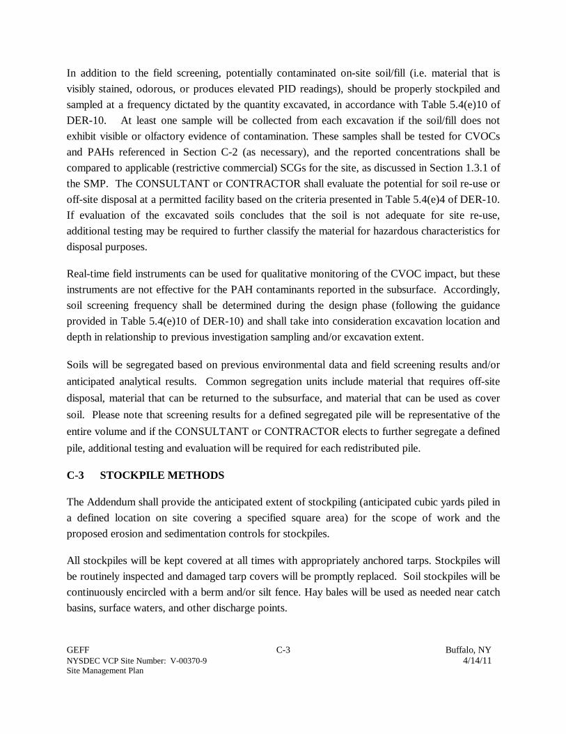
GEFF C-3 Buffalo, NYNYSDEC VCP Site Number: V-00370-9 4/14/11Site Management Plan
In addition to the field screening, potentially contaminated on-site soil/fill (i.e. material that is
visibly stained, odorous, or produces elevated PID readings), should be properly stockpiled and
sampled at a frequency dictated by the quantity excavated, in accordance with Table 5.4(e)10 of
DER-10. At least one sample will be collected from each excavation if the soil/fill does not
exhibit visible or olfactory evidence of contamination. These samples shall be tested for CVOCs
and PAHs referenced in Section C-2 (as necessary), and the reported concentrations shall be
compared to applicable (restrictive commercial) SCGs for the site, as discussed in Section 1.3.1 of
the SMP. The CONSULTANT or CONTRACTOR shall evaluate the potential for soil re-use or
off-site disposal at a permitted facility based on the criteria presented in Table 5.4(e)4 of DER-10.
If evaluation of the excavated soils concludes that the soil is not adequate for site re-use,
additional testing may be required to further classify the material for hazardous characteristics for
disposal purposes.
Real-time field instruments can be used for qualitative monitoring of the CVOC impact, but these
instruments are not effective for the PAH contaminants reported in the subsurface. Accordingly,
soil screening frequency shall be determined during the design phase (following the guidance
provided in Table 5.4(e)10 of DER-10) and shall take into consideration excavation location and
depth in relationship to previous investigation sampling and/or excavation extent.
Soils will be segregated based on previous environmental data and field screening results and/or
anticipated analytical results. Common segregation units include material that requires off-site
disposal, material that can be returned to the subsurface, and material that can be used as cover
soil. Please note that screening results for a defined segregated pile will be representative of the
entire volume and if the CONSULTANT or CONTRACTOR elects to further segregate a defined
pile, additional testing and evaluation will be required for each redistributed pile.
C-3 STOCKPILE METHODS
The Addendum shall provide the anticipated extent of stockpiling (anticipated cubic yards piled in
a defined location on site covering a specified square area) for the scope of work and the
proposed erosion and sedimentation controls for stockpiles.
All stockpiles will be kept covered at all times with appropriately anchored tarps. Stockpiles will
be routinely inspected and damaged tarp covers will be promptly replaced. Soil stockpiles will be
continuously encircled with a berm and/or silt fence. Hay bales will be used as needed near catch
basins, surface waters, and other discharge points.
GEFF C-4 Buffalo, NYNYSDEC VCP Site Number: V-00370-9 4/14/11Site Management Plan
Stockpiles will be inspected at a minimum once each week and after every storm event. Results
of inspections will be recorded in a logbook and maintained at the site and available for inspection
by NYSDEC.
C-4 MATERIALS EXCAVATION AND LOAD OUT
The Addendum will provide details regarding the extent of excavation (i.e., cubic yards, location
of excavation and depth) and load out as part of the scope of work and the proposed methods to
be followed for materials loading and on-site management prior to leaving the site.
A qualified environmental professional or person under their supervision will oversee all invasive
work and the excavation and load-out of all excavated material.
The current owner of the property and its contractors are solely responsible for safe execution of
all invasive and other work performed under this Plan.
The presence of utilities and easements on the site will be investigated by the qualified
environmental professional. It will be determined whether a risk or impediment to the planned
work under this EWP is posed by utilities or easements on the site.
Loaded vehicles leaving the site will be appropriately lined, tarped, securely covered, manifested,
and placarded in accordance with appropriate Federal, State, local, and New York State
Department of Transportation (NYSDOT) requirements (and all other applicable transportation
requirements).
Locations where vehicles enter or exit the site shall be inspected daily for evidence of off-site soil
tracking.
The qualified environmental professional will be responsible for ensuring that all egress points for
truck and equipment transport from the site are clean of dirt and other materials derived from the
site during intrusive excavation activities. Cleaning of the adjacent streets will be performed as
needed to maintain a clean condition with respect to site-derived materials.
C-5 MATERIALS TRANSPORT OFF-SITE
The Addendum shall propose the protocol to be followed for materials management while in
transport off-site, including volume/weight limits per truck. The Addendum will also include truck
transport routes and maps illustrating these routes.

GEFF C-5 Buffalo, NYNYSDEC VCP Site Number: V-00370-9 4/14/11Site Management Plan
All transport of materials will be performed by licensed haulers in accordance with appropriate
local, State, and Federal regulations, including 6 New York Codes Rules and Regulations
(NYCRR) Part 364. Haulers will be appropriately licensed and trucks properly placarded.
Material transported by trucks exiting the site will be secured with tight-fitting covers. Loose-
fitting canvas-type truck covers will be prohibited. If loads contain wet material capable of
producing free liquid, truck liners will be used.
All trucks loaded with site materials will exit the vicinity of the site using only these approved
truck routes. This is the most appropriate route and takes into account: (a) limiting transport
through residential areas and past sensitive sites; (b) use of city mapped truck routes; (c)
prohibiting off-site queuing of trucks entering the facility; (d) limiting total distance to major
highways; (e) promoting safety in access to highways; and (f) overall safety in transport; [(g)
community input [where necessary]]
Trucks will be prohibited from stopping and idling in the neighborhood outside the project site.
Egress points for truck and equipment transport from the site will be kept clean of dirt and other
materials during site remediation and development.
Queuing of trucks will be performed on-site in order to minimize off-site disturbance. Off-site
queuing will be prohibited.
C-6 MATERIALS DISPOSAL OFF-SITE
The Addendum will propose the methods to be followed for materials disposal off-site, including
the off-site disposal locations for excavated soil. All soil, fill, and solid waste excavated and
removed from the site will be treated as contaminated and regulated material unless analytical
results confirm otherwise. Any contaminated and regulated material will be transported and
disposed in accordance with all local, State (including 6NYCRR Part 360) and Federal
regulations. If disposal of soil/fill from this site is proposed for unregulated off-site disposal (i.e.
clean soil removed for development purposes), a formal request will be made to the NYSDEC.
Unregulated off-site management of materials from this site will not occur without NYSDEC
approval.
Off-site disposal locations for excavated soils will include estimated quantities and a breakdown
by class of disposal facility if appropriate, i.e. hazardous waste disposal facility, solid waste

GEFF C-6 Buffalo, NYNYSDEC VCP Site Number: V-00370-9 4/14/11Site Management Plan
landfill, petroleum treatment facility, C/D recycling facility, etc. Actual disposal quantities and
associated documentation will be reported to the NYSDEC in the Periodic Review Report. This
documentation will include: waste profiles, test results, facility acceptance letters, manifests, bills
of lading, and facility receipts.
Non-hazardous historic fill and contaminated soils taken off-site will be handled, at minimum, as a
Municipal Solid Waste per 6NYCRR Part 360-1.2. Material that does not meet Track 1
unrestricted soil cleanup objectives (SCOs) is prohibited from being taken to a New York State
recycling facility (6NYCRR Part 360-16 Registration Facility).
C-7 MATERIALS REUSE ON-SITE
Any material originating from the site can be reused on site provided sampling demonstrates
compliance with the restricted commercial use SCOs defined in 6 NYCRR Part 275-6.8(b). This
criterion for on-site reuse is defined in Section 1.3.1 of the SMP with individual constituent levels
listed in Table 5 of the SMP. Soil sampling will be conducted in accordance with Section C-2.
The qualified environmental professional will ensure that procedures defined for materials reuse in
this SMP are followed and that unacceptable material does not remain on-site. Contaminated on-
site material, including historic fill and contaminated soil, that is acceptable for re-use on-site will
be placed below the demarcation layer or impervious surface (i.e. paved surface or topsoil), and
will not be reused within a cover soil layer, within landscaping berms, or as backfill for subsurface
utility lines.
On site stockpiling or storage will follow the methods discussed in Section C-3. Planned sizes
and locations of stockpiles on site will be provided in the Addendum.
Any demolition material proposed for reuse on-site will be sampled for asbestos and the results
will be reported to the NYSDEC for acceptance. Concrete crushing or processing on-site will not
be performed without prior NYSDEC approval. Organic matter (wood, roots, stumps, etc.) or
other solid waste derived from clearing and grubbing of the site will not be reused on-site.
C-8 FLUIDS MANAGEMENT
Shallow groundwater on Site has historically been encountered at depths greater than 6 feet
below ground surface. If excavation is anticipated to extend below six feet, preparations should
be made to address fluid management.

GEFF C-7 Buffalo, NYNYSDEC VCP Site Number: V-00370-9 4/14/11Site Management Plan
All liquids to be removed from the site, including excavation dewatering and groundwater
monitoring well purge and development waters, will be handled, transported and disposed in
accordance with applicable local, State, and Federal regulations. Dewatering, purge and
development fluids will not be recharged back to the land surface or subsurface of the site, but
will be managed off-site unless otherwise approved by NYSDEC.
Discharge of water generated during large-scale construction activities to surface waters (i.e. a
local pond, stream or river) will be performed under a State Pollution Discharge Elimination
System (SPDES) permit.
C-9 COVER SYSTEM RESTORATION
After the completion of soil removal and any other invasive activities the cover system will be
restored in a manner that complies with the SMP, which serves as the controlling document for
the ICs and ECs required in the Declaration of Covenants and Restrictions dated July 20, 2005
(hereinafter referred to as “the Declaration”). If a “Remaining Contamination Zone” is
encountered, a demarcation layer, consisting of orange snow fencing material or equivalent
material will be placed in the excavation during backfilling activities to provide a visual reference
to the top of the ‘Remaining Contamination Zone,’ the zone that requires adherence to special
conditions for disturbance of remaining contaminated soils defined in this SMP. If the type of
cover system changes from that which exists prior to the excavation (i.e., a soil cover is replaced
by asphalt), this will constitute a modification of the cover element of the remedy and the upper
surface of the ‘Remaining Contamination. A figure showing the modified surface will be included
in the subsequent Periodic Review Report and in any updates to the SMP.
C-10 BACKFILL FROM OFF-SITE SOURCES
All materials proposed for import onto the site will be approved by the qualified environmental
professional and will be in compliance with provisions in this SMP prior to receipt at the site.
All proposed materials shall be in compliance with the requirements set forth in Section 5.4(e) of
the DER-10, including:
Comply with appropriate site-specific SCGs (currently commercial use 6 NYCRR Part375 SCOs for the Site);
Be free of extraneous debris or solid waste;

GEFF C-8 Buffalo, NYNYSDEC VCP Site Number: V-00370-9 4/14/11Site Management Plan
Be recognizable soil or other unregulated material as set forth in 6 NYCRR Part 360 andmaterials for which NYSDEC has issued a beneficial use determination (BUD);
Not exceed the allowable constituent levels for imported fill or soil listed in Table 5.4(e)4of DER-10, which is either unrestricted use or commercial use if a site-specific exemptionis provided by NYSDEC under 6 NYCRR Part 360; and
Confirmation that the source material complies with appropriate SCGs and constituent levels
through sampling of the appropriate sample types prescribed in Table 5.4(e)10 and quantities
outlined in Section 5.4(e)3ii of DER-10.
Material from industrial sites, spill sites, or other environmental remediation sites or potentially
contaminated sites will not be imported to the site.
All imported soils will meet the backfill and cover soil quality standards established in 6NYCRR
375-6.7(d). Based on an evaluation of the land use, protection of groundwater and protection of
ecological resources criteria, the resulting soil quality standards are for unrestricted use, unless
otherwise approved by NYSDEC if in compliance with the site specific SCGs. Individual
constituent concentrations for unrestricted use are listed in Table 5 of the SMP. The commercial
use SCGs are set forth in Part 375 -6.8(b). Soils that meet ‘exempt’ fill requirements under 6
NYCRR Part 360, but do not meet backfill or cover soil objectives for this site, will not be
imported onto the site without prior approval by NYSDEC. Solid waste will not be imported
onto the site.
Trucks entering the site with imported soils will be securely covered with tight fitting covers.
Imported soils will be stockpiled separately from excavated materials and covered to prevent dust
releases.
C-11 STORMWATER POLLUTION PREVENTION
Because the Site is 0.5 acres in size, any excavation and/or construction on Site is not likely to be
sufficient to require a Stormwater Pollution Prevention Plan (SWPPP). Regardless, appropriate
measures shall be taken to minimize the potential for stormwater to impact pollution on Site.
Silt fencing or hay bales will be installed around the entire perimeter of the construction area.
Barrier and hay bale checks will be installed and inspected once a week and after every storm
event. Results of inspections will be recorded in a logbook and maintained at the site and
available for inspection by NYSDEC. All necessary repairs shall be made immediately.
GEFF C-9 Buffalo, NYNYSDEC VCP Site Number: V-00370-9 4/14/11Site Management Plan
Accumulated sediments will be removed as required to keep the barrier and hay bale check
functional.
All undercutting or erosion of the silt fence toe anchor shall be repaired immediately with
appropriate backfill materials.
Manufacturer's recommendations will be followed for replacing silt fencing damaged due to
weathering.
Erosion and sediment control measures identified in the SMP shall be observed to ensure that they
are operating correctly. Where discharge locations or points are accessible, they shall be
inspected to ascertain whether erosion control measures are effective in preventing significant
impacts to receiving waters
C-12 CONTINGENCY PLAN
Upon the discovery of an unknown source of contamination that may require remediation (i.e.
underground storage tanks [USTs], stained soil, drums, etc.), all field activities shall be halted
and appropriate notifications shall be made to ensure that emergency response and cleanup is
conducted as necessary, including pumping fluids from discovered tanks, containers, or the
excavation/pit and properly containing the fluids. Identification of unknown or unexpected
contaminated media (confirmed by screening) during invasive site work will be promptly
communicated by phone to NYSDEC’s Project Manager. If applicable, reportable quantities of
petroleum product will also be reported to the NYSDEC spills hotline. The CONSULTANT will
develop a remedial investigation work plan to investigate the nature and extent of the discovered
source of contamination for NYSDEC review and approval. Sampling will be performed on
product, sediment, and surrounding soils, etc. as necessary to determine the nature of the material
and proper disposal method. Chemical analysis will be performed for full a full list of analytes
(target analyte list [TAL] metals; target compound list (TCL) volatile organic compounds (VOCs)
and semivolatile organic compounds (SVOCs), TCL pesticides and polychlorinated biphenyls
[PCBs]), unless the site history and previous sampling results provide a sufficient justification to
limit the list of analytes. In this case, a reduced list of analytes will be proposed to the NYSDEC
for approval prior to sampling.
These findings will be also included in the periodic reports prepared pursuant to Section 5 of the
SMP.

GEFF C-10 Buffalo, NYNYSDEC VCP Site Number: V-00370-9 4/14/11Site Management Plan
C-13 COMMUNITY AIR MONITORING PLAN
Real-time air monitoring for volatile organic vapors (i.e., VOCs) and particulates (i.e., dust) will
be conducted at the perimeter of the Exclusion Zone during the excavation or drilling/geoprobe
programs if such programs are reasonably expected to create a risk of potential residential
exposure to the contaminants of concern. Based on the expected prevailing wind direction from
the southwest, one upgradient location from the southwest and two downgradient locations from
the northeast shall be selected as air sampling stations. These locations will be adjusted on a daily
or more frequent basis based on actual wind directions to maintain this configuration. In addition
to these locations, a fourth monitoring station will be located in the western edge of the Site,
immediately adjacent to the residential neighbor. This monitoring will be conducted as follows:
Volatile organic vapors and dust particulates (less than 10 mm in size [PM-101]) willbe continuously monitored using instruments capable of displaying 15-minuteaverages, at the downwind perimeter of the exclusion zone. If total volatile organicvapor levels exceed 5 ppm above background, work activities will be halted, untillevels drop below 5 ppm, monitoring would be continued under the provisions of aVapor Emission Response Plan (Section C-13.1). All readings will be recorded and beavailable for NYSDEC and NYSDOH personnel to review if requested.
If the downwind PM-10 particulate level is 100 micrograms per cubic meter (mcg/m3)greater than background (upwind perimeter) for the 15-minute period or if airbornedust is observed leaving the work area, then dust suppression techniques must beemployed. Work may continue with dust suppression techniques provided thatdownwind PM-10 particulate levels do not exceed 150 mcg/m3 above the upwind leveland provided that no visible dust is migrating from the work area. If, afterimplementation of dust suppression techniques, downwind PM-10 particulate levelsare greater than 150 mcg/m3 above the upwind level, work must be stopped and a re-evaluation of activities initiated. Work can resume provided that dust suppressionmeasures and other controls are successful in reducing the downwind PM-10particulate concentration to within 150 mcg/m3 of the upwind level and in preventingvisible dust migration.
C-13.1 Vapor Emission Response Plan
If the total volatile organic vapor concentrations monitored by a PID at the downwind perimeter
of the work area persist between 5 ppm and 25 ppm above background, activities will be halted
and monitoring continued. If the total volatile organic vapor level decreases below 5 ppm above
background, work activities can resume. If the total volatile organic vapor levels are greater than
5 ppm over background but less than 25 ppm over background at the perimeter of the Exclusion
GEFF C-11 Buffalo, NYNYSDEC VCP Site Number: V-00370-9 4/14/11Site Management Plan
Zone, activities must be halted, the source of vapors identified, corrective actions taken to abate
emissions, and monitoring continued. After these steps, work activities can resume provided the
organic vapor level 200 feet downwind of the Exclusion Zone or half the distance to the nearest
residential structure to the west, whichever is less, is below 5 ppm over background for the 15-
minute average.
If the total volatile organic vapor level is above 25 ppm at the perimeter of the Exclusion Zone,
activities must be shut down. When work shutdown occurs, downwind air monitoring as directed
by the Site HSO will be implemented to ensure that vapor emission does not impact the nearest
residential or commercial structure at levels exceeding those specified in the Major Vapor
Emission Response Plan (Section C-13.2). Exceedances of these action levels will be reported to
NYSDEC and New York State Department of Health (NYSDOH) Project Managers.
C-13.2 Major Vapor Emission Response Plan
If any total volatile organic vapor levels greater than 5 ppm over background are identified 200
feet downwind from the Exclusion Zone or half the distance to the nearest residential or
commercial property, whichever is less, all work activities will be halted.
If, following the cessation of work activities, or as the result of an emergency, total volatile
organic vapor levels persist above 5 ppm above background 200 feet downwind from the
Exclusion Zone or half the distance to the nearest residential or commercial property, then the air
quality will be monitored within 20 feet of the perimeter of the nearest residential or commercial
structure (20-foot zone).
If efforts to abate the emission source are unsuccessful and total volatile organic vapor levels
approaching 5 ppm persist for more than 30 minutes in the 20-foot zone, then the Major Vapor
Emission Response Plan shall automatically be placed into effect. Also, the Major Vapor
Emission Response Plan shall be immediately placed into effect if 20-foot zone total volatile
organic vapor levels are greater than 10 ppm above background. Exceedances of these action
levels will be reported to NYSDEC and New York State Department of Health (NYSDOH)
Project Managers.
GEFF C-12 Buffalo, NYNYSDEC VCP Site Number: V-00370-9 4/14/11Site Management Plan
Upon activation of the Major Vapor Emission Response Plan, the following activities will be
undertaken:
All Emergency Response authorities, the Erie County Department of Health orNYSDOH, and NYSDEC will immediately be contacted by the Site HSO and advisedof the situation.
Air monitoring will be conducted at 15 minute intervals within the 20-foot zone. Iftwo successive readings below action levels are measured, air monitoring may behalted or modified by the Site HSO.
C-14 ODOR CONTROL PLAN
Based on the current understanding of the site conditions, it is not anticipated that a large scale
odor nuisance will be encountered. Regardless, this odor control plan includes appropriate
measures of controlling emissions of nuisance odors off-site. Specific odor control methods to be
used on a routine basis will include limiting the size of excavations and stockpiles and covering
them when not active. If nuisance odors are identified at the site boundary, or if odor complaints
are received, work will be halted and the source of odors will be identified and corrected. Work
will not resume until all nuisance odors have been abated. NYSDEC and NYSDOH will be
notified of all odor events and of any other complaints about the project. Implementation of all
odor controls, including the halt of work, is the responsibility of the property owner’s
Remediation Engineer, and any measures that are implemented will be discussed in the Periodic
Review Report.
Various control measures will be employed as warranted to prevent on- and off-site nuisances.
These measures may include: (a) limiting the area of open excavations and size of soil stockpiles;
(b) shrouding open excavations with tarps and other covers; and (c) using foams to cover exposed
odorous soils. If odors develop and cannot be otherwise controlled, additional means to eliminate
odor nuisances may be implemented, including: (d) direct load-out of soils to trucks for off-site
disposal; (e) use of chemical odorants in spray or misting systems; and, (f) use of staff to monitor
odors in surrounding neighborhoods.
If nuisance odors develop during intrusive work that cannot be corrected, or where the control of
nuisance odors cannot otherwise be achieved due to on-site conditions or close proximity to
sensitive receptors, odor control will be achieved by sheltering the excavation and handling areas
in a temporary containment structure equipped with appropriate air venting/filtering systems.
GEFF C-13 Buffalo, NYNYSDEC VCP Site Number: V-00370-9 4/14/11Site Management Plan
C-15 DUST CONTROL PLAN
The Addendum shall include a dust suppression plan that addresses the anticipated dust
management during invasive on-site work, taking into account the scope of work, anticipated area
to be affected, and the seasonal conditions. If the extent of anticipated excavation requires it, the
dust control plan will include the items listed below:
Dust suppression will be achieved though the use of dedicated on-site water truck for roadwetting. The truck will be equipped with a water cannon capable of spraying waterdirectly onto off-road areas including excavations and stockpiles.
Gravel will be used on roadways to provide a clean and dust-free road surface.
On-site roads will be limited in total area to minimize the area required for water trucksprinkling.
C-16 OTHER NUISANCES
Based on the location of the Site, the nature and extent of the impacted soil reported to-date, and
surrounding neighborhood, potential nuisances that may develop during excavation or
construction activities include noise control. Accordingly, the Addendum will include a noise
control plan that will require all activities associated with excessive noise to be conducted during
acceptable times of the day and that on-site field instruments will monitor the decibel levels on site
and at the property boundaries. These measures will be developed and utilized by the contractor
for all remedial work to ensure compliance with local noise control ordinances.
If the excavation/construction activities involve demolition of structures or tree removal, then a
plan for rodent control will be developed as part of the Addendum and utilized by the contractor
prior to and during site clearing and site grubbing, and during all remedial work.
A plan will be developed and utilized by the contractor for all remedial work to ensure compliance
with local noise control ordinances.
APPENDIX D
HEALTH AND SAFETY PLAN

GEFF 1 Buffalo, NYNYSDEC VCP Site Number: V-00370-9 12/7/10Site Management Plan
APPENDIX D
HEALTH AND SAFETY PLAN TEMPLATE*
December 7, 2010
*THIS HASP IS UN-EXECUTED; PREPARED AS A TEMPLATE FOR USE IN DEVELOPINGA CONTRACTOR-SPECIFIC, SCOPE-SPECIFIC PLAN DEPENDING ON PROJECTASSIGNMENTS AT THE SITE. THIS APPENDIX IS NOT TO BE CONSTRUED AS AHEALTH AND SAFETY PLAN FOR ANY PROJECT. THIS PLAN MUST BE REVISED ASAPPROPRIATE TO ADDRESS CHANGING SITE CONDITIONS, SITE SAFETY CONTROLS,CONTRACTOR ASSIGNMENTS, AND/OR MODIFIED SCOPE OF WORK.
Approved:
Project Manager Date
Approved:
Health, Safety, and Environment Manager Date
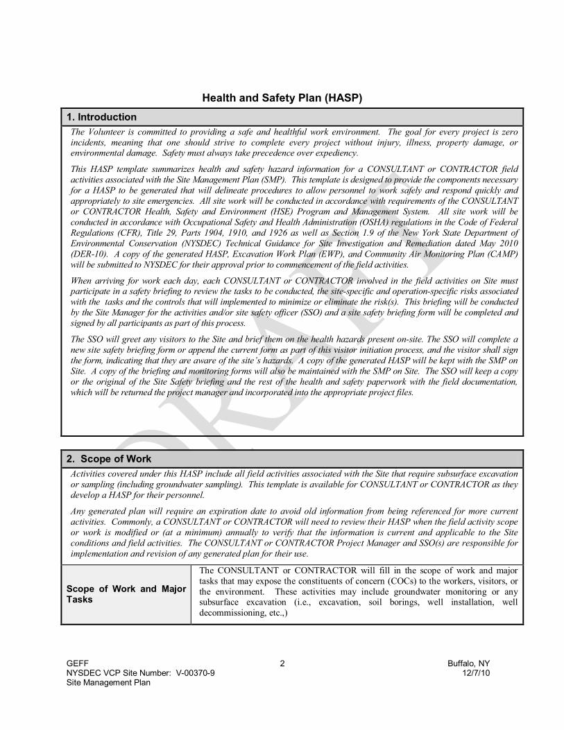
GEFF 2 Buffalo, NYNYSDEC VCP Site Number: V-00370-9 12/7/10Site Management Plan
Health and Safety Plan (HASP)
1. Introduction
The Volunteer is committed to providing a safe and healthful work environment. The goal for every project is zeroincidents, meaning that one should strive to complete every project without injury, illness, property damage, orenvironmental damage. Safety must always take precedence over expediency.
This HASP template summarizes health and safety hazard information for a CONSULTANT or CONTRACTOR fieldactivities associated with the Site Management Plan (SMP). This template is designed to provide the components necessaryfor a HASP to be generated that will delineate procedures to allow personnel to work safely and respond quickly andappropriately to site emergencies. All site work will be conducted in accordance with requirements of the CONSULTANTor CONTRACTOR Health, Safety and Environment (HSE) Program and Management System. All site work will beconducted in accordance with Occupational Safety and Health Administration (OSHA) regulations in the Code of FederalRegulations (CFR), Title 29, Parts 1904, 1910, and 1926 as well as Section 1.9 of the New York State Department ofEnvironmental Conservation (NYSDEC) Technical Guidance for Site Investigation and Remediation dated May 2010(DER-10). A copy of the generated HASP, Excavation Work Plan (EWP), and Community Air Monitoring Plan (CAMP)will be submitted to NYSDEC for their approval prior to commencement of the field activities.
When arriving for work each day, each CONSULTANT or CONTRACTOR involved in the field activities on Site mustparticipate in a safety briefing to review the tasks to be conducted, the site-specific and operation-specific risks associatedwith the tasks and the controls that will implemented to minimize or eliminate the risk(s). This briefing will be conductedby the Site Manager for the activities and/or site safety officer (SSO) and a site safety briefing form will be completed andsigned by all participants as part of this process.
The SSO will greet any visitors to the Site and brief them on the health hazards present on-site. The SSO will complete anew site safety briefing form or append the current form as part of this visitor initiation process, and the visitor shall signthe form, indicating that they are aware of the site’s hazards. A copy of the generated HASP will be kept with the SMP onSite. A copy of the briefing and monitoring forms will also be maintained with the SMP on Site. The SSO will keep a copyor the original of the Site Safety briefing and the rest of the health and safety paperwork with the field documentation,which will be returned the project manager and incorporated into the appropriate project files.
2. Scope of Work
Activities covered under this HASP include all field activities associated with the Site that require subsurface excavationor sampling (including groundwater sampling). This template is available for CONSULTANT or CONTRACTOR as theydevelop a HASP for their personnel.
Any generated plan will require an expiration date to avoid old information from being referenced for more currentactivities. Commonly, a CONSULTANT or CONTRACTOR will need to review their HASP when the field activity scopeor work is modified or (at a minimum) annually to verify that the information is current and applicable to the Siteconditions and field activities. The CONSULTANT or CONTRACTOR Project Manager and SSO(s) are responsible forimplementation and revision of any generated plan for their use.
Scope of Work and MajorTasks
The CONSULTANT or CONTRACTOR will fill in the scope of work and majortasks that may expose the constituents of concern (COCs) to the workers, visitors, orthe environment. These activities may include groundwater monitoring or anysubsurface excavation (i.e., excavation, soil borings, well installation, welldecommissioning, etc.,)
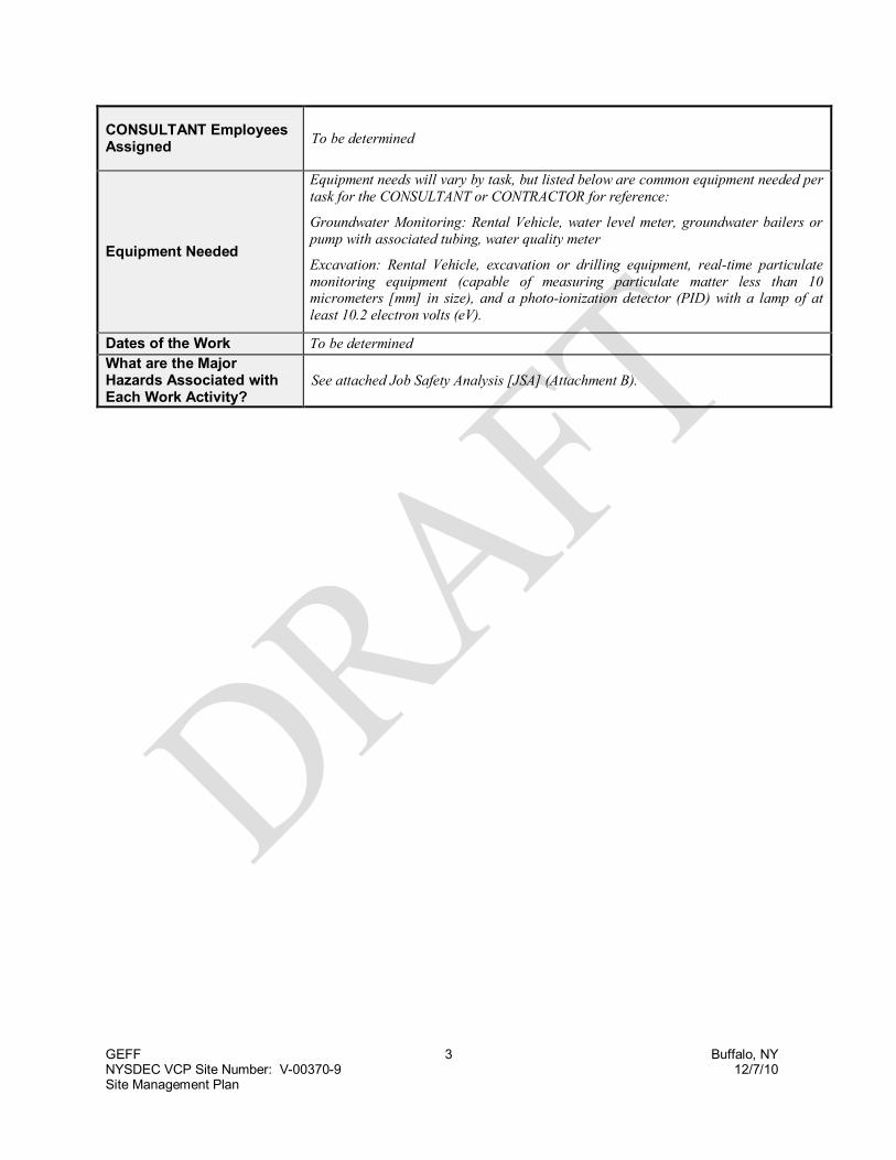
GEFF 3 Buffalo, NYNYSDEC VCP Site Number: V-00370-9 12/7/10Site Management Plan
CONSULTANT EmployeesAssigned
To be determined
Equipment Needed
Equipment needs will vary by task, but listed below are common equipment needed pertask for the CONSULTANT or CONTRACTOR for reference:
Groundwater Monitoring: Rental Vehicle, water level meter, groundwater bailers orpump with associated tubing, water quality meter
Excavation: Rental Vehicle, excavation or drilling equipment, real-time particulatemonitoring equipment (capable of measuring particulate matter less than 10micrometers [mm] in size), and a photo-ionization detector (PID) with a lamp of atleast 10.2 electron volts (eV).
Dates of the Work To be determined
What are the MajorHazards Associated withEach Work Activity?
See attached Job Safety Analysis [JSA] (Attachment B).

GEFF 4 Buffalo, NYNYSDEC VCP Site Number: V-00370-9 12/7/10Site Management Plan
3. Key Personnel -
Position Name Phone NumbersProject Manager
Field Supervisor
Owner Representative
Office HSE Representative
Regional HSE Manager
Occupational Health Manager
4. Task/ Operation Health and Safety Hazard Assessment
Site Locationand History
The Site is located at the southern corner of Seneca Avenue and Kingston Place at thefollowing address: 2137 Seneca Street, Buffalo, NY 14210
As illustrated on Figure 2 of the SMP, the current Site has historically contained up to sevenparcels facing Seneca Street (2137 through 2153 Seneca Street) and five parcels alongKingston Place (93 through 101 Kingston Place). Previous uses of the Site includeresidential dwellings, a pharmacy, a retail tire establishment, automotive service building,offices, and a dry cleaning establishment. The dry cleaning establishment was located at2141 Seneca Street (northeast corner of the property) from the 1950s until 1982. Drycleaning chemicals (namely tetrachloroethene or PCE) were presumably released to theenvironment from the aforementioned establishment resulting in chlorinated volatile organiccompounds (CVOCs) that have impacted the soil and groundwater. The source ofpolynuclear aromatic hydrocarbons (PAHs) reported on Site is unclear, but may havederived from asphalt fill or automotive service activities.
Remediation activities were conducted between 2003 and 2009. A summary of theRemaining Contamination on Site, as well as the Institutional and Engineering Controls(ICs/ECs) that protect the public health from exposure to the contamination, is presented inthe SMP.
ChemicalHazards
The following chemicals were identified during previous site investigations and remediationefforts that were conducted between 1999 and 2009:
CVOCs: PCE, Trichloroethene (TCE), 1,1-Dichloroethene (1,1-DCE),cis-1,2-Dichloroethene (cis-1,2-DCE), trans -1,2-Dichloroethene (trans-1,2-DCE),and vinyl chloride.
PAHs: Benzo(a)anthracene, Benzo(a)pyrene, Benzo(b)flouranthene,benzo(k)flouranthene, chrysene, and dibenz(a,h)anthracene
PhysicalHazards
The Site is located in an urban setting. Common physical hazards to be listed include:- Awareness of conditions that may cause one to slip, trip, fall;- Potential underground utilities;- Hazards associated with weather conditions (temperature, precipitation, wind, etc.,);- Hazards that may be associated with machinery used to accomplish the task (i.e., moving
parts or pressurized lines on a drilling rig or backhoe, etc.,)
Potential for poisonous snakes, plants and spiders, insects, mosquitoes, ticks, animaldroppings, small biting animals and wildlife, and domestic pets.

GEFF 5 Buffalo, NYNYSDEC VCP Site Number: V-00370-9 12/7/10Site Management Plan
BiologicalHazards
Chemical, physical, and biological hazards will be minimized through ECs and ICs, andwhen necessary, personal protective equipment (PPE). Site specific controls are addressedin the JSA contained in Attachment C-2.
Hazard Controls Insect repellent, observe proper rail and near water safety procedures.
7. Personal Protective Equipment (PPE)
All site personnel
Work clothes as appropriate Gloves (nitrile surgical type inner and/or leather) as appropriate Hard hat when overhead hazards or heavy equipment are present Safety toe boots with good tread Safety glasses with side shields ANSI Class 2 high visibility apparel for work near roads or heavy
equipment (Class 3 apparel is required for work at night or during periodsof poor visibility)
All personnel working inareas where action levels areexceeded – see Section 8
Appropriate coveralls (Tyvek or equivalent) Outer nitrile gloves Full-face air purifying respirator with organic vapor cartridges. To use a
respirator, employees must be trained, fit tested and medically qualified.
5. Employee Medical Qualifications and Training Requirements
All personnel
All personnel will participate in documented daily health andsafety tailgate meetings to discuss site conditions, hazards,and hazard controls.
All personnel who are not required by project activities to haveHAZWOPER training must have current field safety training.
Personnel entering the exclusion zone40-hour HAZWOPER training with a current 8-hour refresherand medical qualification
Field Supervisor and/or Site Safety Officer8-hour HAZWOPER Supervisor Training
First Aid Training for remote sites
6. Engineering and Administrative Controls
CONSULTANT will implement engineering and administrative controls to reduce the spread of contamination,isolate contaminants, shield workers, prohibit access to hazardous areas, warn of physical hazards and/orotherwise minimize the likelihood of worker injury or exposure. Specific engineering and administrative controlsfor each CONSULTANT activity are listed in the JSA (Attachment C-2).

GEFF 6 Buffalo, NYNYSDEC VCP Site Number: V-00370-9 12/7/10Site Management Plan
8. Air Monitoring
Air monitoring will be conducted with a PID with a 10.2 eV lamp (or higher) calibrated to isobutylene to evaluateconcentrations of volatile organic compounds (VOCs). The monitoring equipment must be calibrated inaccordance with the manufacturer's instructions. In addition, the results of daily instrument calibrations must berecorded in the field notes. Continuous monitoring is required during intrusive work. Document readings in thefield notes. Additional monitoring with a combustible gas meter (CGI) may be required to enter an excavation orconfined space (refer to Attachment C-2).
Air Monitoring Action Levels
Analyzer Reading Location Duration Action Personal Protective Equipment
<1 ppm POO/RSP/OBZ NA Continue monitoring at 15 minute intervals.
Minimum Site Ensemble(Hardhat, Steel-toed Boots, EyeProtection, Safety Vest, Long-sleevedshirt, Gloves)
>1 ppm OBZ > 1 minute
Use colorimetric tube or vinylchloride/benzene specific monitor to checkfor vinyl chloride/benzene; if not present ator above 0.5 ppm continue monitoring andthe action level is 25 ppm (see below).
Minimum Site Ensemble
Action Levels below assume vinyl chloride is present.
1 ppm vinyl chloride orbenzene
OBZ > 1 minuteMonitor OBZ; don protective clothing;establish work zones; provide respiratoryprotection; establish decon area.
Minimum Site Ensemble, PLUS:Tyvek coveralls, Nitrile Outer Gloves(if product or product saturated soilsare encountered), Nitrile Inner Gloves,Chemical Resistant Steel-toed Boots(or chemical resistant covers oversteel-toed boots) at discretion of SSOdepending on the potential forexposure; full-face respirators withorganic vapor cartridges
>5 ppm vinyl chlorideor benzene
OBZ > 1 minute
Stop work; move upwind while vaporsdissipate. If elevated levels remain, coverexcavation and spoils, evacuate upwind andnotify RHSEM or PM.
As specified by RHSEM
Action Levels below assume vinyl chloride is not detected.
<25 ppm POO/RSP/OBZ NA Continue monitoring at 15 minute intervals. Minimum Site Ensemble
>25 ppm POO/RSP/OBZ >1 minuteMonitor OBZ; don protective clothing;establish work zones
Minimum Site Ensemble, PLUS:Nitrile Outer Gloves, (if product orproduct saturated soils areencountered), and Nitrile InnerGloves, Chemical Resistant Steel-toedBoots (or chemical resistant coversover steel-toed boots) at discretion ofSSO depending on the potential forexposure
>25 ppm OBZ >1 minute Provide respiratory protection.Add full-face respirators with organicvapor cartridges
>250 ppm OBZ>5continuousminutes
Stop work; move upwind while vaporsdissipate. If elevated levels remain,evacuate upwind and notify RHSEM or PM.
As specified by RHSEM
POO- Point of Operation RSP- Release Source Point OBZ- Operators Breathing Zone
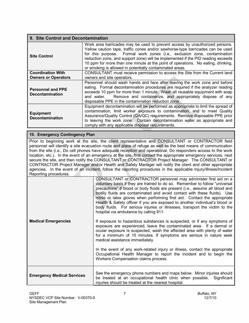
GEFF 7 Buffalo, NYNYSDEC VCP Site Number: V-00370-9 12/7/10Site Management Plan
9. Site Control and Decontamination
Site Control
Work area barricades may be used to prevent access by unauthorized persons.Yellow caution tape, traffic cones and/or sawhorse-type barricades can be usedfor this purpose. Formal work zones (i.e., exclusion zone, contaminationreduction zone, and support zone) will be implemented if the PID reading exceeds10 ppm for more than one minute at the point of operations. No eating, drinking,or smoking is allowed in potentially contaminated areas.
Coordination WithOwners or Operators
CONSULTANT must receive permission to access the Site from the Current landowners and site operators.
Personnel and PPEDecontamination
Personnel should wash hands and face after leaving the work zone and beforeeating. Formal decontamination procedures are required if the analyzer readingexceeds 10 ppm for more than 1 minute. Wash all reusable equipment with soapand water. Remove and containerize, and appropriately dispose of anydisposable PPE in the contamination reduction zone.
EquipmentDecontamination
Equipment decontamination will be performed as appropriate to limit the spread ofcontamination, limit worker exposure to contamination, and to meet QualityAssurance/Quality Control (QA/QC) requirements. Remove disposable PPE priorto leaving the work zone. Contain decontamination water as appropriate andcomply with any applicable disposal requirements.
10. Emergency Contingency Plan
Prior to beginning work at the site, the client representative and CONSULTANT or CONTRACTOR fieldpersonnel will identify a site evacuation route and place of refuge as well as the best means of communicationfrom the site (i.e., Do cell phones have adequate reception and operational, Do responders access to the worklocation, etc.). In the event of an emergency at the site, first contact the appropriate emergency services, nextsecure the site, and then notify the CONSULTANT or CONTRACTOR Project Manager. The CONSULTANT orCONTRACTOR Project Manager and/or Health and Safety Manager will notify the client and other appropriateagencies. In the event of an incident, follow the reporting procedures in the applicable Injury/Illness/IncidentReporting procedures.
Medical Emergencies
CONSULTANT or CONTRACTOR personnel may administer first aid on avoluntary basis if they are trained to do so. Remember to follow “universalprecautions” if blood or body fluids are present (i.e., assume all blood andbodily fluids are contaminated and avoid contact with these fluids). Usenitrile or latex gloves when performing first aid. Contact the appropriateHealth & Safety officer if you are exposed to another individual’s blood orbody fluids. For serious injuries or illnesses, transport the victim to thehospital via ambulance by calling 911.
If exposure to hazardous substances is suspected, or if any symptoms ofexposure are experienced, leave the contaminated area. If a dermal orocular exposure is suspected, wash the affected area with plenty of waterfor a minimum of 15 minutes. If symptoms are serious in nature seekmedical assistance immediately.
In the event of any work-related injury or illness, contact the appropriateOccupational Health Manager to report the incident and to begin theWorkers Compensation claims process.
Emergency Medical ServicesSee the emergency phone numbers and maps below. Minor injuries shouldbe treated at an occupational health clinic when possible. Significantinjuries should be treated at the nearest hospital.
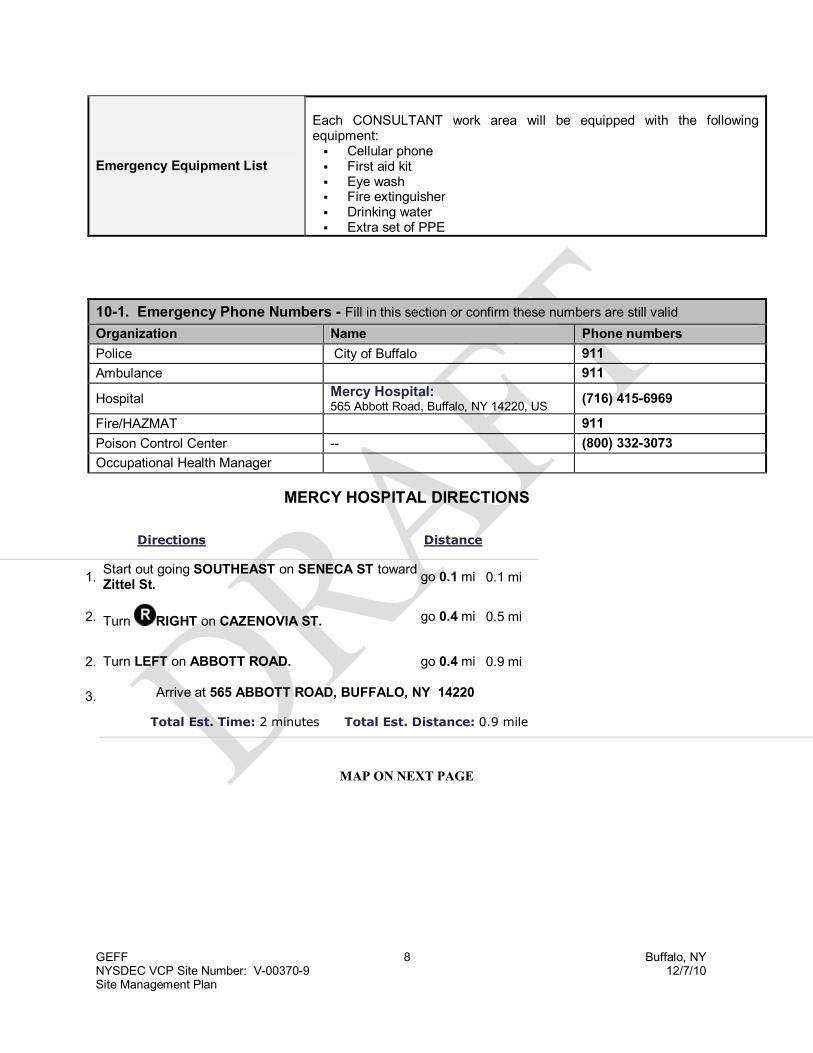
GEFF 8 Buffalo, NYNYSDEC VCP Site Number: V-00370-9 12/7/10Site Management Plan
10-1. Emergency Phone Numbers - Fill in this section or confirm these numbers are still valid
Organization Name Phone numbers
Police City of Buffalo 911
Ambulance 911
HospitalMercy Hospital:565 Abbott Road, Buffalo, NY 14220, US
(716) 415-6969
Fire/HAZMAT 911
Poison Control Center -- (800) 332-3073
Occupational Health Manager
MERCY HOSPITAL DIRECTIONS
Directions Distance
1.Start out going SOUTHEAST on SENECA ST towardZittel St.
go 0.1 mi 0.1 mi
2. Turn RIGHT on CAZENOVIA ST. go 0.4 mi 0.5 mi
2. Turn LEFT on ABBOTT ROAD. go 0.4 mi 0.9 mi
3. Arrive at 565 ABBOTT ROAD, BUFFALO, NY 14220
Total Est. Time: 2 minutes Total Est. Distance: 0.9 mile
MAP ON NEXT PAGE
Emergency Equipment List
Each CONSULTANT work area will be equipped with the followingequipment: Cellular phone First aid kit Eye wash Fire extinguisher Drinking water Extra set of PPE

GEFF 9 Buffalo, NYNYSDEC VCP Site Number: V-00370-9 12/7/10Site Management Plan
The CONSULTANT or CONTRACTOR may elect to designate an occupational clinic for treatmentof non-emergency injuries or illnesses. Most communities have several clinics available and theCONSULTANT or CONTRACTOR will likely contact potential clinics in advance if their companyhas a preferred provider or to verify whether the clinics accept walk-ons and the payment termsacceptable for the clinic. An example of such text would include:
All non-emergency injuries should be referred to the occupational clinic listed below. Before visiting thisclinic, the site safety officer or the employee’s supervisor should call ahead to verify that the clinic cantreat the injury to be brought in.
Occupational Clinic
Hospital Phone No. ( ) -
Driving Directions1. Start out going _____________toward _____________
2. After traveling ____ mile, Turn ______ on ________________.
3. Travel ____ mile before arriving at __________, CITY , NY Zip Code
Total Distance: _____ mile
Total Estimated Time: 2 minutes
[INSERT MAP HERE]
ATTACHMENT D-1EXAMPLE SIGNATURE FORM

I hereby certify that I understand the safety and health guidelines containedin the CONSULTANT or CONTRACTOR Health and Safety Plan for the fieldactivities associated with the Site.
(Employee Name)
(Employee Signature) (Date)
In case of emergency, please contact:
1.(Name) (Relationship) (Phone No.)
2.(Name) (Relationship) (Phone No.)
Received by:
____Health and Safety Officer or Field Supervisor (Date)

ATTACHMENT D-2JOB SAFETY ANALYSIS (JSA) FORM CONSIDERATIONS

JOB SAFETY ANALYSIS (JSA)Develop separate JSAs for each separate work task as appropriate.
The JSA should be a working document that is used and revised as appropriate in the field.
General Physical Hazards and ControlsPotential Hazards Controls
Use hazard recognition tools to identify hazards in the following categories: Motion Environment (also see the biological hazards section below) Chemical (see the chemical hazards section below) Energized Systems
Add any additional hazards and controls (e.g., engineering controls, administrative controls, PPE) and deletenon applicable hazards and controls.
SUGGESTIONS FOR THE CONSULTANT OR CONTRACTOR TOCONSIDER WHEN DEVELOPING POTENTIAL HAZARDS FOR
THEIR SCOPE OF WORK
What am I about to do?Have I stepped through the task in my mind?
Do I really understand the task?Have I done this task before?
What could go wrong?What could move slip or fall?
Does the equipment need to be checked?Could something spill, splash or leak?What could be done to make it safer?
Should I get help with the task?Do I have the right tools or equipment?
Do I need to review the JSA/Procedures?What have I done to communicate the hazards?Have I spoken to my team about the hazards?
Have I informed others in the area?Does someone know where I am and what I am about to do?
All hazards
Manage projects so that adequate time is allowed to complete tasks Manage projects so that proper equipment is available Maintain and encourage a positive safety attitude/culture Look out for yourself and others at the site; provide direct feedback to
each other on safety performance Report near misses and safety observations per company policy Employees must review this Health and Safety Plan prior to work, and a copy
must be available at the work site Reevaluate the Job Safety Analysis daily; consider changes in weather
conditions, work activities, and other site conditions Conduct a daily safety briefing or tailgate meeting

General Physical Hazards and ControlsPotential Hazards Controls
Heavy equipment
Discuss work activities and location of ground personnel with equipmentoperators prior to work
Wear high-visibility clothing Stay away from equipment when possible Make eye contact with the operator prior to approaching equipment Have the operator de-energize equipment prior to approaching Watch out for blind spots Inspect equipment prior to work Operators must maintain three points of contact (i.e., two hands and one foot
secured on steps/rails, one hand and two feet secured on steps/rails, etc.,)when entering equipment
Noise Use hearing protection when heavy equipment is operating
Aggressive individuals orpotentially dangerous
locations (e.g. high crimeareas or deserted
buildings)
Get approval from property owners prior to access and see if the owner willaccompany you
Work in teams of two or more If you are alone maintain contact with someone at the office Leave and/or contact help if you are threatened
Driving/vehicle safety
Inspect vehicles before use
Avoid driving when drowsy
Obey traffic rules
Use extra caution when entering roadways or backing
Completely exit roadways to park
Do not operate vehicles in unsafe conditions (e.g., on steep slopes, in deepmud)
Use a tow strap and proper procedures to remove a vehicle that is stuck inmud or snow
Do not use cell phones and avoid other distractions when operating vehicles
Secure all loads, including equipment within the cab
Wear seat belts
Leave enough time to get to your destination without hurrying
Never follow to close
Avoid backing when possible
Be aware of heavy equipment and do not park or conduct work in the blind spotof the equipment operator; remember that “blind spots” of some equipment canbe very large
Verify back-up alarms are functional for all heavy equipment; for pick-ups orSUVs with obstructed rear view, a back-up alarm or use a spotter whenbacking up
Cold stress
Stay inside when possible during extreme cold
Schedule outdoor work during mild weather
Stay dry
Dress in layers
Have a warm hat and socks available
Take breaks in heated areas

General Physical Hazards and ControlsPotential Hazards Controls
Heat stress
Stay inside when possible during extreme heat
Drink plenty of liquids and have plenty of water available in the field
Take breaks in a cool area as necessary
Wear a hat and use sun screen
Wear loose fitting, light colored clothing
Moisten clothing to promote cooling
Avoid excessive alcohol or caffeine the night before work
Go someplace cool if you feel ill Seek medical attention if symptoms of heat exhaustion or heat stroke appear
(e.g., dizzy, pale dry skin, confusion)
Severe weather
Check the radio or internet for severe weather warnings
Check road conditions with the state highway department
During high winds watch for blowing doors, gates and other objects
During lightning follow the 20/20 rule – if you hear thunder with 20 seconds ofseeing lightning, take a 20 minute break
Know safe locations and/or evacuation routes in case of severe weather suchas hurricanes and tornadoes
Lifting
Healthy employees should lift no more than 50 pounds – know your personallimit
Get help to lift heavy objects Bend at the knees; do not use your back Do not twist during lifts Minimize the movement of heavy objects Pack items to keep their weight below 50 pounds Stretch before lifting Store heavy objects off the ground
Sharp objects
Wear appropriate work safety-toe boots and work gloves Use caution when working with any hand tool Whenever possible use safety cutting tools instead of fixed open blade knives Periodically inspect tools and equipment to insure that they remain in good
operating condition Watch out for barbed wire and electrical fences
Slips, trips, and falls
Maintain good housekeeping When possible, avoid steep and uneven terrain Wear sturdy boots with good tread Keep the work area free from water, ice or debris Literally, watch where you step – mark slip, trip, fall hazards with flagging, etc. Take the time to find a safe route to the desired location Do not perform any activity with a fall exposure of 6 feet (1.8 meters)
(construction industry) or 4 feet (1.2 meters) (general industry) or more withoutusing fall protection
Use a backpack to avoid carrying too many items

General Physical Hazards and ControlsPotential Hazards Controls
Vehicle traffic
Implement traffic control in accordance with the Manual on Uniform TrafficControl Devices (MUTCD) if lane closures are required
Contact the responsible authority for the road to determine if a right-of-waypermit is required
For shoulder work and work near roadways, use a combination of orangecones and vehicle placement to ensure the work zone is protected frommotorists
Wear ANSI Class 2 high-visibility vests (Class 3 for night work or work whenthere is low visibility)
Expect the unexpected
Fire/Explosion Use proper procedures to prevent flash, fire, or an explosion
Confined space entry
Confined spaces have limited means for entry and exit and are not designedfor occupancy
Entry to a confined space requires training, air monitoring, special equipmentand rescue provisions
Simply crossing the plane of the space with any part of your body is consideredan entry
Chemical Hazards and ControlsPotential Hazards Controls
Potential ProcessChemical Release Hazard
Develop and Review daily emergency meeting locations with allparticipants
Identify or install visible windsocks for quick identification of winddirection.
Identify route(s) to emergency meeting locations
Potential chemical hazards
Use nitrile gloves when handling potentially contaminated materials Implement site control Stay up wind from contamination Minimize handling or contaminated materials Contain or cover contaminated materials to minimize release of vapors or
dust particulate that may contain contaminants Using good personal hygiene practices; wash hands and face prior to eating
or drinking) The “buddy system” must be used in hazardous areas Refer to provisions throughout this HASP
Hazardous materials Material Safety Data Sheets (MSDS) must be available for all chemicals
brought on site (e.g., sample preservatives, decontamination solutions) Label all containers with chemical name and hazard warning Use protective gear recommended on the MSDS

Biological Hazards and ControlsPotential Hazards Controls
Ticks
Deer ticks can carry Lyme disease, other ticks can carry Rocky MountainSpotted Fever and other disease
Use repellants containing DEET and/or permethrin
Wear light colored clothing so you can see ticks
Perform tick checks periodically and at the end of the day
Poisonous plants
Know how to identify poison oak and poison ivy and avoid it
Burning or cutting poison plants can cause respiratory problems
Oils from these plants can transfer from clothing to equipment and causereactions
Vectorborne disease
Hantavirus may be present in mouse droppings or nesting materials
Histoplasmosis may be present in bird droppings
Plague may be transmitted by fleas
Do not generate dust from areas impacted by mouse or bird droppings Eliminate locations for potential mouse and bird nests in equipment storage
areas
Stay away from all animals especially if they appear to be ill or injured
Others
Use caution when lifting objects that may provide shelter for spiders, snakes,hornets and rodents
Use repellant with DEET if mosquitoes are a problem at the site
Domestic and wild animals are all biological hazards to consider

APPENDIX E
SITE-WIDE INSPECTION FORMS
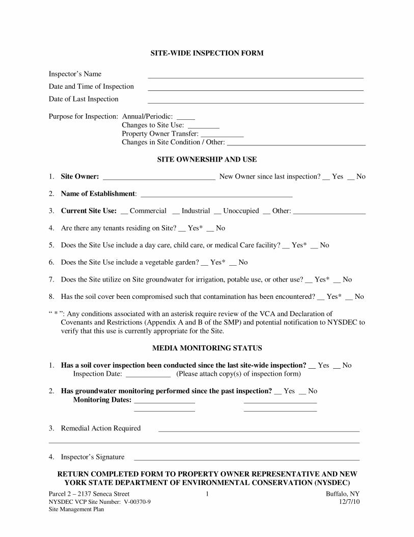
Parcel 2 – 2137 Seneca Street 1 Buffalo, NY
NYSDEC VCP Site Number: V-00370-9 12/7/10 Site Management Plan
SITE-WIDE INSPECTION FORM
Inspector’s Name
Date and Time of Inspection
Date of Last Inspection
Purpose for Inspection: Annual/Periodic:
Changes to Site Use:
Property Owner Transfer: Changes in Site Condition / Other:
SITE OWNERSHIP AND USE
1. Site Owner: New Owner since last inspection? Yes No
2. Name of Establishment:
3. Current Site Use: Commercial Industrial Unoccupied Other:
4. Are there any tenants residing on Site? Yes* No
5. Does the Site Use include a day care, child care, or medical Care facility? Yes* No
6. Does the Site Use include a vegetable garden? Yes* No
7. Does the Site utilize on Site groundwater for irrigation, potable use, or other use? Yes* No
8. Has the soil cover been compromised such that contamination has been encountered? Yes* No
“ * ”: Any conditions associated with an asterisk require review of the VCA and Declaration of Covenants and Restrictions (Appendix A and B of the SMP) and potential notification to NYSDEC to
verify that this use is currently appropriate for the Site.
MEDIA MONITORING STATUS
1. Has a soil cover inspection been conducted since the last site-wide inspection? Yes No Inspection Date: (Please attach copy(s) of inspection form)
2. Has groundwater monitoring performed since the past inspection? Yes No
Monitoring Dates:
3. Remedial Action Required
4. Inspector’s Signature
RETURN COMPLETED FORM TO PROPERTY OWNER REPRESENTATIVE AND NEW
YORK STATE DEPARTMENT OF ENVIRONMENTAL CONSERVATION (NYSDEC)

Parcel 2 – 2137 Seneca Street 1 Buffalo, NY
NYSDEC VCP Site Number: V-00370-9 12/7/10 Site Management Plan
INSPECTION FORM
COVER SYSTEM
Inspector’s Name
Date and Time of Inspection
Date of Last Inspection
Purpose for Inspection: Annual/Periodic:
Post-excavation or surface repair: After significant weather events:
Observed damage requiring inspection / Other:
INSPECTION CHECKLIST
1. Vegetative cover along Kingston Place
Walk the length of the vegetative cover. Comments
• Are there any bare spots in the vegetation cover? Yes No
• Are there any signs of damaged or diseased vegetation? Yes No
• Are there any signs of excessive erosion? Yes No
• Is there new root exposure or new woody plants
established? Yes No
• Are there any signs of burrowing animals? Yes No
• Any other Observations?
2. Sidewalk along Kingston Place and Seneca Street, walkways around building, Asphalt
pavement associated with parking lot and access way to road Walk the length of the sidewalks. Comments
• Are there any cracks greater than ½-inch apart? Yes No
• Are there any signs of raised pavement associated with
plant roots or subsurface subsidence? Yes No
• Are there any signs of extensive deterioration of pavement? Yes No
• Any other Observations?
3. Remedial Action Required
4. Inspector’s Signature
RETURN COMPLETED FORM TO PROPERTY OWNER REPRESENTATIVE

APPENDIX F
MONITORING WELL BORING AND CONSTRUCTION LOGS
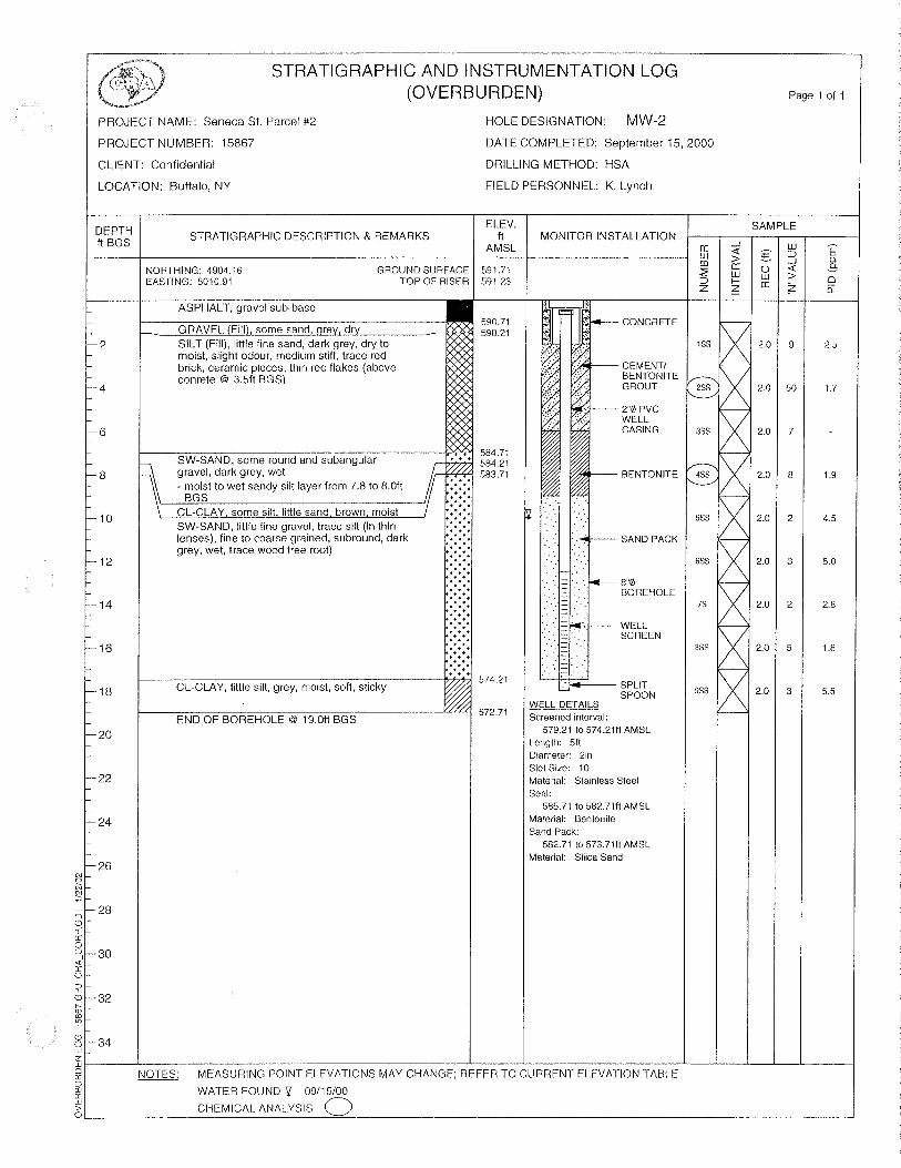
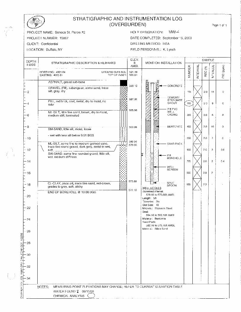


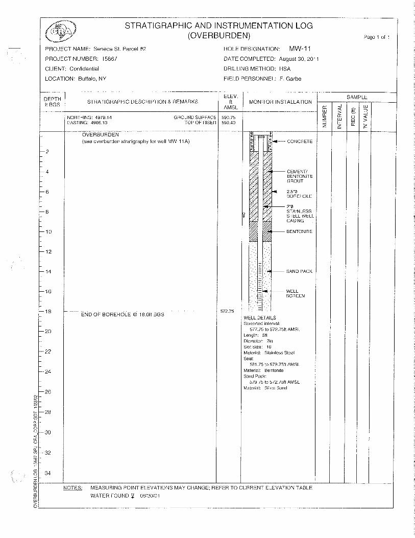
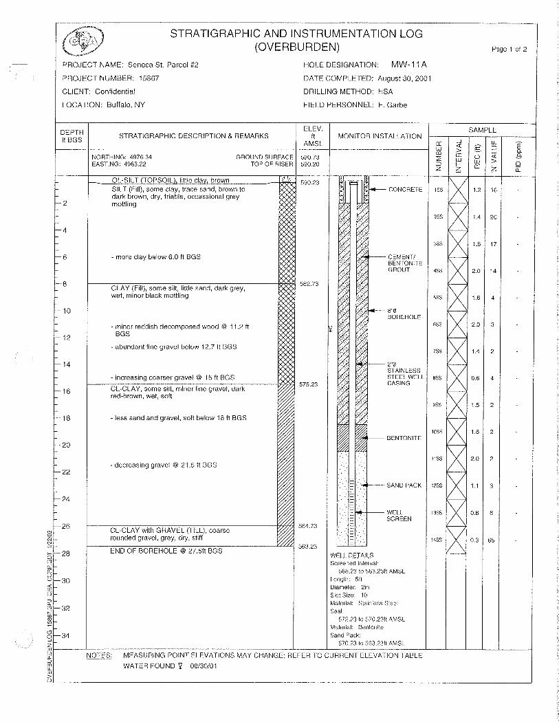


APPENDIX G
GROUNDWATER MONITORING WELL SAMPLING LOG FORM

Site Name / Number: Date:
Owner: By:
Location: Meas. Method
Well
Number Time Notes
Feet Feet
MEASUREMENT OF GROUNDWATER LEVELS
Feet
Parcel 2 - 2137 Seneca St. / VCA 00370-9
Buffalo, NY
/ /
Depth to WaterWater
Elevation
Elevation of
Reference
NYSDEC VCA V-00370-9
GE Capital Franchise Finance
14964473.00803
Parcel 2 - 2137 Seneca St.
Buffalo, NY
12/7/10

Well Data Sheet
Job Name/Number: Parcel 2 – 2137 Seneca Street / VCA 00370-9 Location Buffalo, NY
Monitoring Well Identification MW - Sampling Order
WELL INSPECTION:
1. Reported Total Well Depth(ft.)
2. Measured Total Well Depth(ft.): -
3. Sediment Thickness (ft.): (if thickness is greater than 2 feet, redevelop well)
4. Is the flush-mounted well protector attached and properly sealed? (if no, then repair/replace)
5. Is there water present in the well protector vault? (if yes, then evaluate source of leak and repair)
6. Is well locking cap locked and sealed? (if no, then correct accordingly).
7. Can downhole equipment be lowered to well bottom? (if no, then evaluate whether well requires
redevelopment, repair, or decommissioning).
LIQUID LEVEL DATA Date/Time / /
Measured By
1. Reported Total Well Depth(ft.)
2. Depth to Water(ft.): -
3. Thickness of Liquid Column(ft.):
4. Conversion Coefficient from thickness to purge volume: x 0.50 gal/ft. (use 0.125 for 1-inch well)
5. Calculated Purge Volume (3 well volumes):
PURGE AND SAMPLE DATA Date/Time / /
Sampled By
Photo Ionization Detector Reading NA
Calibration of pH meter in Field 4pH 7pH 10pH________not done
Final volume of water purged (gal) Did well go dry Time to recover
Field pH measurements (units)
Field Conductivity (umhos/cm)
Field Temperature meas (°F)
Field ORP measurements (mV)
Sample Odor and Color:
Sample Sediment Content
Weather Conditions
Were Sampling Splits or Duplicates collected at this well:
Samples Shipped To Date Samples were shipped
Method of Shipment- Fedex Hand Delivered Other
COMMENTS:
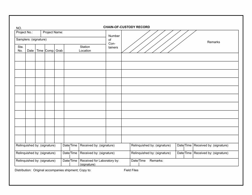
Project No.: Project Name:
Samplers: (signature)Number
of
Con-
tainers
Remarks
Sta.
No. Date Time Comp. Grab
Station
Location
Distribution: Original accompanies shipment; Copy to: Field Files
NO. CHAIN-OF-CUSTODY RECORD
Relinquished by: (signature) Date/Time Relinquished by: (signature)Received by: (signature) Date/Time Received by: (signature)
Relinquished by: (signature) Date/Time Relinquished by: (signature)Received by: (signature) Date/Time Received by: (signature)
Relinquished by: (signature) Date/Time Received for Laboratory by:
(signature)
Date/Time Remarks:

APPENDIX H
QUALITY ASSURANCE PROJECT PLAN
CONTENTS
SECTION PAGE
H-1.0 INTRODUCTION ................................................................................................................. H-1
H-2.0 PROJECT BACKGROUND .................................................................................................. H-1
H-3.0 PROJECT ORGANIZATION AND RESPONSIBILITIES..................................................... H-2H-3.1 NYSDEC PROJECT MANAGER............................................................................ H-2H-3.2 PROJECT COORDINATOR (CONSULTANT) ....................................................... H-2H-3.3 PROJECT MANAGER (CONSULTANT) ............................................................... H-2H-3.4 HEALTH AND SAFETY OFFICER (CONSULTANT) ........................................... H-3H-3.5 QA/QC OFFICER (CONSULTANT) ....................................................................... H-3H-3.6 ANALYTICAL LABORATORY PROJECT MANAGER........................................ H-4H-3.7 FIELD OPERATIONS LEADER (CONSULTANT) ................................................ H-5H-3.8 FIELD TEAM (CONSULTANT)............................................................................. H-5
H-4.0 DATA QUALITY OBJECTIVES .......................................................................................... H-6H-4.1 QUALITY ASSURANCE OBJECTIVES FOR MEASUREMENT DATA ............... H-7
H.4.1.1 Level of Quality Control Effort ................................................................... H-7H.4.1.2 Accuracy, Precision, and Sensitivity of Analysis......................................... H-8H.4.1.3 Completeness, Representativeness, and Comparability................................ H-10
H-5.0 FIELD SAMPLING PLAN (FSP) .......................................................................................... H-11H-5.1 FIELD RECORDKEEPING..................................................................................... H-14H-5.2 CHAIN OF CUSTODY............................................................................................ H-15H-5.3 CALIBRATION RECORDS AND TRACEABILITY OF
STANDARDS/REAGENTS..................................................................................... H-15
H-6.0 SAMPLE CUSTODY ............................................................................................................ H-15H-6.1 FIELD SPECIFIC CUSTODY PROCEDURES........................................................ H-16H-6.2 LABORATORY CHAIN-OF-CUSTODY PROCEDURES....................................... H-17H-6.3 FINAL EVIDENCE FILE CUSTODY PROCEDURE.............................................. H-17
H-7.0 CALIBRATION PROCEDURES AND FREQUENCY.......................................................... H-18
H-8.0 ANALYTICAL PROCEDURES............................................................................................ H-19
H-9.0 INTERNAL QUALITY CONTROL CHECKS ...................................................................... H-19
H-10.0 DATA VALIDATION, REDUCTION, AND REPORTING................................................... H-19H-10.1 DATA REDUCTION............................................................................................... H-20H-10.2 DATA VALIDATION ............................................................................................. H-20H-10.3 DATA REPORTING ............................................................................................... H-20
H-11.0 PERFORMANCE AND SYSTEM AUDITS.......................................................................... H-20H-11.1 PERFORMANCE AUDITS ..................................................................................... H-20H-11.2 SYSTEM AUDITS .................................................................................................. H-22
TABLES(follow text)
Number
H-1 CHLORINATED VOLATILE ORGANIC COMPOUND (CVOC) CHARACTERISTICSH-2 SAMPLING SPECIFICATIONS

CONTENTS(Continued)
ATTACHMENT(follows tables)
Attachment
H-1 NYDEC CP-43: GROUNDWATER MONITORING WELL DECOMMISSIONING POLICY

GEFF H-1 Buffalo, NYNYSDEC VCP Site Number: V-00370-9 12/7/10Site Management Plan
H-1.0 INTRODUCTION
This Quality Assurance Project Plan (QAPP) is specific to the commercial property referred to as
“Parcel 2,” 2137 Seneca Street, Buffalo, New York (Site) and has been prepared for the
monitoring activities outlined in the Site Management Plan (SMP) dated December 2010.
The objectives of this QAPP are to provide valid data and documentation for monitoring the
progress of the groundwater remediation efforts and potentially evaluating the volatile organic
compound (VOC) soil vapor intrusion (SVI) potential in the north quadrant of the Site. This
QAPP provides comprehensive information regarding the Site investigation organization,
personnel responsibilities, and sets forth specific procedures to be used during sampling and data
analyses. This QAPP also describes the specific protocols that will be followed for sampling,
sample handling and storage, chain of custody, and laboratory (and field) analysis.
H-2.0 PROJECT BACKGROUND
This QAPP provides QA/QC criteria for performing monitoring activities associated with Section
3 of the SMP (Site Monitoring Plan). The monitored chlorinated VOCs (CVOCs) include
tetrachloroethene (PCE) and its breakdown products trichloroethene (TCE), cis-1,2-
dichloroethene (cis-1,2-DCE), and vinyl chloride. Table H-1 lists the CVOCs and their
characteristics and methods for detection, as criteria for field screening of subsurface materials
and identifying impact. Currently, semi-annual groundwater monitoring is being conducted to
evaluate the progress of groundwater remediation. In addition to the laboratory analytical method
listed in Table H-2, field parameters of temperature, specific conductance, pH, and oxidation-
reduction potential (ORP) are collected at each sampled well.
The current groundwater monitoring network for the Site is illustrated on Figure 15 of the SMP
and includes shallow monitoring wells MW-2, MW-4, MW-13, MW-11, PZ-A and deep
monitoring well MW-4A. These wells provide adequate coverage for monitoring the source area
(MW-4) and providing lateral delineation (MW-2, MW-11, MW-13, and PZ-A) and vertical
delineation (MW-4A).
Although it is not currently scheduled, an evaluation of the SVI potential may be conducted in
accordance with protocols outlined in the New York State Department of Health (NYSDOH)
Guidance for Evaluating SVI in the State of New York (dated October 2006). This sampling may
be conducted prior to the re-occupation of the current building or the design and construction of
GEFF H-2 Buffalo, NYNYSDEC VCP Site Number: V-00370-9 12/7/10Site Management Plan
future occupied buildings. The results of the evaluation would determine whether additional
sampling or mitigation systems are necessary for current or planned occupied buildings on site.
H-3.0 PROJECT ORGANIZATION AND RESPONSIBILITIES
The Project Organization at the site is presented in the section. The key project personnel will
include the New York State Department of Environmental Conservation (NYSDEC) Project
Manager, the Project Coordinator (CONSULTANT); Project Manager (CONSULTANT), Health
and Safety and Quality Assurance/Quality Control (QA/QC) officers (CONSULTANT); a
Laboratory Project Manager; a Field Operations Leader; and a Field Team. The responsibilities of
key project personnel are defined herein.
H-3.1 NYSDEC PROJECT MANAGER
The NYSDEC Project Manager for the project serve as a liaison between the Site Consultant or
Contractor and the agency. The NYSDEC Project Manager will also manage the review of all
documents submitted to NYSDEC. He will serve as the point-of-contact for NYSDEC
notifications and will coordinate oversight and split sampling activities as necessary. The Project
Coordinator for the Site will communicate with the NYSDEC Project Manager on all issues
regarding the status of Site Management.
H-3.2 PROJECT COORDINATOR (CONSULTANT)
The Project Coordinator for the site will manage all staff that may be tasked with the
implementation of the elements of this work plan. He will coordinate activities of
CONSULTANT and other contractors working on the project with the operational schedule for
any activities at the site. The Project Coordinator for the site will communicate with the Project
Manager on all issues regarding implementation.
H-3.3 PROJECT MANAGER (CONSULTANT)
The Project Manager has the overall responsibility for project management, and the authority to
commit the resources necessary to meet project objectives and requirements. The project
manager must arrange for technical, financial, and scheduling efforts to be conducted successfully.
The Project Manager will:

GEFF H-3 Buffalo, NYNYSDEC VCP Site Number: V-00370-9 12/7/10Site Management Plan
1) Define objectives and develop a detailed project schedule;
2) Oversee the site work;
3) Establish project policy and procedures to address the specific needs of the project as awhole, as well as the objectives of each task;
4) Confirm that proper materials, instruments and qualified personnel are available;
5) Designate individuals to assist in discharging the QA/QC responsibilities;
6) Oversee the collection, compilation, and review all field and laboratory analytical data, and
7) Coordinate the preparation of reports and take reasonable steps to ensure their quality.
H-3.4 HEALTH AND SAFETY OFFICER (CONSULTANT)
The Health and Safety Officer (HSO) will take reasonable steps to confirm that project-specific
health and safety procedures and applicable regulations are followed to the best of the field crew’s
ability. All field staff and the HSO have the authority to stop project work if such work is not
being completed in accordance to the Health and Safety Plan (HASP) or if unsafe conditions
exist. The HSO will be responsible for the safe completion of field activities and the delegation of
safety supervision in the field to the designated Site Safety Officer (SSO). However, each person
will be responsible for his or her own actions at the site.
H-3.5 QA/QC OFFICER (CONSULTANT)
The QA/QC Officer will be responsible for demonstrating that valid measurement data and routine
assessments have been completed. This will be accomplished through audits that commonly
identify whether proper QA/QC protocols are being implemented. Additionally, regular review of
field notebooks, chain-of-custody forms, and field calibration documents will be conducted.
Finally, notes provided by the laboratory on the chain-of-custody forms and laboratory reports
will be used to confirm the validity of analytical results. The QA officer will be responsible for
reporting results of audits to the Project Manger to allow for adjustment or re-sampling as
needed.

GEFF H-4 Buffalo, NYNYSDEC VCP Site Number: V-00370-9 12/7/10Site Management Plan
H-3.6 ANALYTICAL LABORATORY PROJECT MANAGER
The Analytical Laboratory Project Manger (ALPM) will oversee all independent laboratory
activities to verify that resources of the laboratory are available on an as-required basis and all
analytical work is completed in accordance with all appropriate laboratory protocols. These
protocols include
Chain-of-Custody protocol,
Scheduling sample analysis,
Review of data,
Preparation of analytical reports, and
Final approval of analytical report.
The ALPM is also responsible for delegating QA/QC responsibilities to a qualified QA/QC Officer
who will:
Overview laboratory QA/QC;
Overview QA/QC documentation,
Conduct detailed data review;
Decides laboratory corrective actions, if required, and
Provides technical representation for laboratory QA/QC procedures.
The ALPM is also responsible for performing or delegating sample custodian responsibilities that
include:
Sample container receipt and inspection;
Recording sample container condition;
Signing appropriate documents and verifying correctness of Chain of Custody;
Notifying ALPM and QA/QC Officer of sample receipt and inspection;
Assigning a unique laboratory identification number correlated to the field sampleidentification number, and entering each into the sample receiving bog;
Initiating transfer of samples to the appropriate lab sections with assistance from thelaboratory project manager; and
Controlling and monitoring access to and storing of samples and extracts.

GEFF H-5 Buffalo, NYNYSDEC VCP Site Number: V-00370-9 12/7/10Site Management Plan
The analytical laboratories selected to perform the analyses for which there are United States
Environmental Protection Agency (USEPA) approved methods (i.e., SW-846 methods) will be
full-service chemical analytical laboratories certified by the NYSDOH through the National
Environmental Laboratory Accreditation Program (NELAP).
TestAmerica, Inc. (TestAmerica) is currently the laboratory selected to provide analytical services
for this project. The ALPM will be an employee of TestAmerica (or any other subcontracted
analytical laboratory used for this project).
H-3.7 FIELD OPERATIONS LEADER (CONSULTANT)
The Field Operations Leader (FOL) will be responsible for implementing the fieldwork and for
coordinating the day-to-day activities of the various field and technical staff under his supervision.
The responsibilities of the FOL (Site Manager) will include:
1) The provision of day-to-day coordination with Project Manager on technical issues;
2) The development and implementation of field-related workplans, assurance of schedulecompliance and adherence to management-developed requirements;
3) Coordination and management of field personnel including sampling, drilling,subcontractors, surveying subcontractors, and material handling subcontractors;
4) Implementation of QC for technical data and field measurement data provided by fieldstaff and by the QA/QC Officer, including maintenance of field equipment;
5) Implementation of QC for technical data provided by the Project Manger; and
6) Coordinator and oversight of the subcontractors assisting the CONSULTANT.
The FOL will assign daily work and will supervise drilling subcontractors (if applicable), and
technicians.
H-3.8 FIELD TEAM (CONSULTANT)
The project manager and/or FOL will assign the Field Team (FT) that will obtain all samples (soil,
groundwater, soil vapor, or indoor air) from the site. The FT reports to the FOL with regard to
the execution of the data collection and directs any needed subcontractors, such as drill crews,
excavation crews, etc. The FT reports directly to the FOL while on-site and complies with all
FOL directives.
GEFF H-6 Buffalo, NYNYSDEC VCP Site Number: V-00370-9 12/7/10Site Management Plan
H-4.0 DATA QUALITY OBJECTIVES
As stated in Section 3.0 of the SMP, the project objective is to monitor appropriate media so as to
confirm the subsurface conditions necessary for closure at the site. At this time, groundwater
progress monitoring and confirmation sampling are the only planned activities remaining to be
conducted during the course of the project, but appropriate SVI sampling may be necessary for
the re-occupation of the current building or the design and construction of future occupied
buildings.
The following types of data generated during in the course of this project include:
Field observations of geologic and hydrogeologic conditions including soil andgroundwater characteristics, and CVOC indicators;
Field meter readings including those for measurement of water levels, basic waterchemistry, and CVOC screening;
Field records of onsite activities including sample collection, sample handling, and otheractivities directly tied to the generation of monitoring and confirmation data or the propercontext of data;
Field Records of general field conditions, including weather, surrounding activity (i.e.,interior equipment and supplies, neighborhood road construction or excavation, etc.); and
Results of laboratory analysis of soil and groundwater samples.
The results from the sample collection and testing activities require a significant level of
confidence in order to sufficiently characterize the hydrogeologic, chemical, physical and land use
properties of the facility so that comparisons can be made to Standards, Criteria, and Guidelines
(SCG) criteria defined in the SMP. In order to achieve the objectives, this QAPP is prepared to
provide protocols that will generate accurate and representative field and analytical data necessary
for evaluating the CVOC concentrations.
The quality objectives for these data types are discussed below.
Field Observations: The quality of field observations of geologic and hydrogeologic conditions
relies heavily on the training and experience of the personnel responsible for those activities.
Criteria for performance are established through standard operating procedures for the applicable
activities as presented in Section H-5 of this QAPP. Consequently, the quality objective for these
GEFF H-7 Buffalo, NYNYSDEC VCP Site Number: V-00370-9 12/7/10Site Management Plan
data will be to maintain adherence to the applicable procedures and to maintain proper
documentation.
Field Meter Readings: The quality of field meter readings relies on the proper calibration and
operation of equipment. The criteria for performance are established in the manufacturer’s
specifications, so the quality objective for these data will be to maintain adherence to the
manufacturer’s specifications as referenced in Section H-6 of this QAPP.
Field Records: The quality of field records relies on the training and performance of the field
crew as controlled by the task or project manager. Control will be maintained through
communication of expectations that the observations will be reported diligently and accurately on
the appropriate forms so that a quality record is established. Communication will take place prior
to fieldwork and during fieldwork as necessary to assure quality performance.
Laboratory Results: The results of laboratory analyses are subject to the quality objectives of the
Laboratory Quality Assurance Manual [QAM] (available on request), which specifies methods for
the maintenance and calibration of equipment, handling of samples, execution of test procedures,
and other activities impacting the quality of the generated data
H-4.1 QUALITY ASSURANCE OBJECTIVES FOR MEASUREMENT DATA
The overall QA objectives are to develop and implement procedures for field sampling, chain of
custody, laboratory analysis, and reporting that will provide results that are scientifically valid.
Specific procedures for sampling, chain-of-custody, laboratory instruments calibration, laboratory
analysis, reporting of data, internal QC, preventative maintenance of field equipment, and
corrective action are described in other sections of this document. The purpose of this section is
to state the specific, required QA objectives for accuracy, precision, and representativeness.
H.4.1.1 Level of Quality Control Effort
It is required that field blanks, trip blanks, field duplicates, and matrix spike samples be analyzed
to assess the quality of the data resulting from the field sampling program. It is recommended
that laboratory duplicates (investigative samples split by the laboratory in addition to matrix
spike/matrix spike duplicate (MS/MSD) samples) also be analyzed. Field and trip blanks,
consisting of distilled water, will be submitted to the analytical laboratory with the field samples.
Field blanks are analyzed to check for procedural contamination that may result in sample
contamination. Trip blanks are used to assess the potential for volatile organic contamination of

GEFF H-8 Buffalo, NYNYSDEC VCP Site Number: V-00370-9 12/7/10Site Management Plan
samples due to contamination migration during sample shipment and storage. Field duplicates
provide an estimate of the reproducibility of measurement. Matrix spikes provide information
about the effect the sample matrix has on the accuracy of the result. All matrix spikes should be
performed in duplicates.
Equipment rinseate blanks are not proposed for groundwater-sampling activities because only
dedicated equipment (sample sleeves and disposable bailers), are being used for this activity.
Field and trip blanks, consisting of distilled water, will be submitted to the analytical laboratory to
be analyzed at the following frequency:
Field blanks: One Field blank sample consisting of laboratory-supplied distilled waterdecanted on site into the appropriate sample containers will be collected. This sample willbe analyzed for the same parameters as the investigative samples;
Trip blanks: One trip blank prepared by the laboratory and accompanying the bottleorder will be included for VOCs analysis.
Field duplicates and MS/MSD samples, consisting of the media(s) sampled, will be collected and
submitted to the analytical laboratory at the following frequency:
Field duplicates: One field duplicate for each matrix will be submitted. Samples will beanalyzed for the same parameters as the investigative samples for the matrix;
MS/MSD: One MS/MSD sample set for every 20 or less investigative samples, one foreach matrix sampled. These sample sets will be spiked with target analytes for the givenanalytical procedure, and analyzed with the investigative samples of that matrix.MS/MSD samples will be selected by the analytical laboratory per their internal batchsampling procedures.
H.4.1.2 Accuracy, Precision, and Sensitivity of Analysis
Accuracy measures the bias of a measuring system. Sources of error are the sampling
process, field contamination, preservation, handling, sample matrix, sample preparation, and
analysis techniques. Accuracy will be controlled through the implementation of the laboratory
QA/QC program that will include standards, spiked samples, and field audit samples. The
laboratory QC procedures for analytical testing include the testing of surrogate samples.
MS/MSD for organics are performed at a predetermined frequency as specified by the Laboratory
QAPP provided by the laboratory as part of their internal QA/QC program. Matrix spikes
provide information about the effect the sample matrix has on the accuracy of the result. All
GEFF H-9 Buffalo, NYNYSDEC VCP Site Number: V-00370-9 12/7/10Site Management Plan
matrix spikes should be performed in duplicate. The laboratory QAPPs are confidential but are
available upon request. The QC procedures for analytical testing also include the testing of
method blanks at the beginning of each analytical run. A minimum of one method blank per
matrix per analytical method will be analyzed.
Precision measures the reproducibility of measurements under a given set of conditions.
Specifically, it is a quantitative measure of variability of a group of measurements compared to
their average value. The overall precision of measurement data is a mixture of sampling and
analytical factors. Analytical precision is much easier to control and quantify than sampling
precision. Sampling precision is unique to each site. Precision will be addressed by the
comparison of field replicate sample analyses and laboratory MS/MSD analytical results. The
Relative Percent Difference (RPD) will be calculated between MS and MSD samples. The
analytical results from the field replicate samples provide data on overall measurement precision;
analysis results from the laboratory replicates provide data on analytical precision. Subtracting
the analytical precision from the measurement precision defines the sampling precision:
Sampling Precision = Measurement Precision – Analytical Precision
Precision will be measured through the use of Standard Deviation, and will be dependent upon
two types of QC samples, duplicate and field audit samples. Precision is reported as Percent
Relative Standard Deviation (%RSD) and RPD.
Percent RSD is the coefficient of variance (CV) multiplied by 100, and the coefficient of variance
is the standard deviation (s) divided by the mean. The lower the RSD percent, the more precise
the data. RSD for measurement precision is calculated by a pair of replicates, using the following
formula:
Percent RSD = 100*CV = (s/mean)*100 = {2* (x1-x2)/(x1+x2)} * 100 * (1/2)0.5; where:x1 is measurement #1 of a replicate, andx2 is measurement #2 of a replicate.
RPD is calculated using the following formula:
RPD = ((Cs-Cd)/Cavg)* 100; where
Cs is the sample concentration,Cd is the duplicate sample concentration, andCavg is the average concentration of the sample and the duplicate.
GEFF H-10 Buffalo, NYNYSDEC VCP Site Number: V-00370-9 12/7/10Site Management Plan
H.4.1.3 Completeness, Representativeness, and Comparability
Representativeness expresses the degree to which data accurately and precisely represents a
characteristic of a population, parameter variations at a sampling point, a process condition, and
an environmental condition. Representativeness is a qualitative parameter that is dependent upon
the proper design of the sampling program and proper laboratory protocol. The sampling
network was designed to provide data representative of site conditions. During development of
this network, consideration was given to the existing analytical data and physical setting.
Representativeness will be satisfied by ensuring that the FSP is followed, proper sampling
techniques are used, proper analytical procedures are followed, and sampling holding times are
not exceeded in the laboratory. Representativeness will be assessed by the analysis of field
duplicated samples.
Completeness and representativeness of samples will be controlled through the strict
implementation of sample support and proper chain-of-custody procedures as outlined in this
document.
Control Limits are the maximum and/or minimum values defining a range for a specific parameter,
as outlined within each analytical procedure, considered to satisfactorily meet quality control
criteria. When the parameter falls outside that range, the procedure is considered to be out-of-
control. Whenever the analytical procedure is or becomes out-of-control, corrective action must
be taken to bring the analysis back into control. The corrective action must include: (1) finding
the cause of the problem, (2) correcting the problem, (3) demonstrating the problem has been
corrected by reanalyzing appropriate laboratory reference samples, and (4) repeating the analyses
of any investigative samples that may have been affected by the control problem. Exceptions will
be made, on a case-specific basis. If the control limit is technically impracticable for a particular
sample or analysis, documentation and narrative explanation should be submitted with the data
report and raw data. The documentation must include evidence that a good faith effort was made
to meet the control limit; this will generally include two attempts to analyze the sample.
Comparability objectives provide the needed control over the total measurement process, which is
necessary to demonstrate that data can be compared among various phases of the assessment.
This control reduces the opportunity for variance of data results, both over space and time.
Comparability is controlled through standard American Society for Testing and Materials
(ASTM) sampling protocol as described in the sampling and analysis plans as well as use of SW-
846 methods.

GEFF H-11 Buffalo, NYNYSDEC VCP Site Number: V-00370-9 12/7/10Site Management Plan
H-5.0 FIELD SAMPLING PLAN (FSP)
The sampling procedures are presented to define the field activities to be conducted and protocol
to be followed in order to accomplish the data quality objectives (DQOs). This section is
provided as guidance for the personnel assigned to conduct the activities and discusses in detail
the procedures and specifications required to achieve the level of QA necessary for the data
generated. All field activities, including boring, drilling, and sampling operations, will be
conducted or supervised by a qualified environmental scientist or engineer under the direction of
the Project Coordinator.
The field activities will include groundwater progress monitoring and confirmatory sampling of
the selected shallow and deep monitoring wells.
Each potential stage of the field activities will include tasks that require detailed procedures to
ensure that precise, accurate, representative, complete and comparable data will be generated
during these tasks. These tasks are listed below:
Groundwater Sampling
Groundwater Level Measurements
Groundwater Sampling.
Soil and Groundwater Sample Preparation and Analysis
Monitoring Well Decommissioning
Boring Location Selection and Safety Consideration
Monitoring Well and Piezometer Decommissioning
Possible Additional Tasks
SVI Testing
Groundwater Level Measurement: Depth-to-groundwater will be measured in each well to an
accuracy of 0.01 foot prior to groundwater sampling. Water level measurements from all wells
will be collected without interruption to minimize the potential for water level variations over time
to influence the interpretation of groundwater flow. Measurement of groundwater levels and the
bottom depth for each well will involve use of a single electronic water level meter. The depth-
to-groundwater will be measured by lowering the probe on the meter into the well until the meter

GEFF H-12 Buffalo, NYNYSDEC VCP Site Number: V-00370-9 12/7/10Site Management Plan
sounds indicating contact with water. The marked length on the cable intersecting the reference
elevation point as the probe signals water contact (audible or visible) will be identified as the
depth to water from the top of inner casing (TOIC). The probe will be raised slightly and lowered
again to verify its accurate depth. The well bottom depth will be measured by observing when the
gravitation pull on the cable ceases, thus indicating that the probe is resting on the bottom of the
well. The verified reading will be recorded on appropriate data forms for groundwater level
measurements and a Well Data Sheet (example included in Appendix G).
The depth-to-water measurement and the reported well depth will be used to calculate the volume
of standing water and the volume of water needing to be purged (a minimum of three times the
standing water in the well). These calculations will be recorded on a Well Data Sheet (example
included in Appendix G).
Groundwater Sampling: Groundwater sampling will be conducted once adequate purging has
been performed to ensure that representative groundwater samples will be collected from the
monitoring well. Purging and sampling are currently being performed under low-flow methods
using a peristaltic pump with disposable tubing connected to a flow-through cell.
Low-flow sampling method is designed to ensure that groundwater is drawn passively from the
formation with minimal mixing of stagnant water associated with casing storage. Groundwater
will be purged at a flow rate that limits groundwater level drawdown as measurements of water
quality parameters (temperature, specific conductance, pH, and ORP) have stabilized as defined
below:
Field Parameter Stabilization RangepH 0.25 Standard UnitsSpecific conductance 10%Temperature 0.5 oCORP 10 mVTurbidity NTU
If conventional sampling is implemented using disposable polyethylene bailers or other pumping
methods, the procedure will involve purging of the well until three well volumes of water have
been removed and measurements of selected water quality parameters (temperature, specific
conductance, and pH) have stabilized as defined below:
Field Parameter Stabilization Range
GEFF H-13 Buffalo, NYNYSDEC VCP Site Number: V-00370-9 12/7/10Site Management Plan
pH 0.25 Standard Units (SU)Specific conductance 10%Temperature 0.5 oCTurbidity (Optional) NTU
Boring Location Selection and Safety Consideration: All planned boring or monitoring well
locations will be marked prior to drilling. The CONSULTANT and the property owner or
manager will coordinate underground utility searches for both the exterior and the interior of the
building. Boring locations will be adjusted as necessary to avoid identified or suspected utilities.
In addition to the common safety concerns associated with drilling that are addressed in a
generated HASP for the task, borings may be installed within the building interior. Therefore,
measures will be taken to enhance air circulation while combustion engines associated with any
equipment are used within the building or other potential air stagnating locations. These measures
may include opening doors and/or windows and the use of box-style fans and/or fans present at
the facility. Air monitoring using a carbon monoxide (CO) meter and a combustible gas indicator
(CGI) will be performed during equipment operation as well. If CO concentrations exceed 5 parts
per million (ppm) or CGI readings exceed 10 percent of the lower explosive limit (LEL), work
will be stopped and the situation remedied either by further enhancing air circulation or waiting
until the levels have subsided below these values.
Monitoring Well and Piezometer Decommissioning: All monitoring well and piezometer
decommissioning shall be performed in accordance with NYSDEC’s CP-43: “Groundwater
Monitoring Well Decommissioning Policy.” This documentation (provided as Appendix H-1 in
this document) provides considerations for determining the best decommissioning method and
procedures for performing the task.
Soil Sampling and Screening: Soil samples will be collected continuously and split into 1-foot
or 2-foot intervals for geologic classification screening, and potential submittal for analysis.
Subsurface conditions will be logged on a boring log (example will be included in a task-specific
work plan) based on the sample recovery. Other observations such as odor and visual signs of
COC impact or disturbance will also be noted. Soil samples will be visually classified in the field
according to the descriptive terminology of the Unified Soil Classification System (USCS)
presented in ASTM D-2488.
Soil samples will be screened for total VOCs that are detectable using a calibrated 10.2 eV
photoionization detector (PID) or equivalent instrument. Any contamination observed on a visual
GEFF H-14 Buffalo, NYNYSDEC VCP Site Number: V-00370-9 12/7/10Site Management Plan
basis or through sample screening with the PID will be noted on the boring log. Within each 1-
foot or 2-foot interval, a representative portion of the recovered soil sample will also be
transferred into a resealable zip-lock plastic bag for PID headspace measurements. The sealed
bagged sample will be provided time for potential COCs to volatilize within the bag for screening
by inserting the tip of the PID into a minimal opening in the bag to measure the headspace of the
sample.
Soil and Groundwater Sample Preparation and Analysis: Soil samples selected for potential
laboratory analysis will be collected using USEPA SW-846 field method 5035. One method
commonly used when following field method 5035 involves the extracting of three undisturbed
plugs of soil from the sample interval and transferring each into a separate 40 milliliter (40-ml)
glass vial. Two of the vials contain water and a third vial contains methanol. The samples will be
stored in ice-chilled coolers and shipped via overnight courier to an accredited laboratory where
the samples are placed in a freezer within 48 hours after sample collection. In addition to the vial
samples, soil can also collected in a 2-ounce glass container without any preservation for
evaluating moisture content. Laboratory-supplied sample vials and containers will be used for all
samples collected.
Groundwater samples are transferred directly into the appropriate pre-labeled laboratory-supplied
containers with preservative, and immediately placed in an ice-chilled cooler. At the end of each
sampling round, sample coolers will be packed and shipped to the analytical laboratory under
chain-of-custody protocol by overnight courier.
Submitted soil and groundwater samples selected for VOC analysis will be tested using USEPA-
approved Method 8260B (SW-846 8260B), as described in the USEPA publication, Test
Methods for Evaluation of Solid Wastes, Physical/Chemical Methods (SW-846, 3rd Edition,
Update III). These samples have a maximum 14-day holding time, as stated in Table H-2.
H-5.1 FIELD RECORDKEEPING
Field records will be written in indelible ink. Specific field documentation protocols are left up to
the discretion of the Project Manager. However, procedures for reviewing, approving, and
revising field records must be clearly defined and stated in the QAPP. At a minimum, all
documentation errors shall be corrected by drawing a single line through the error so that it
remains legible; the error must then be initialed by the responsible individual and the date of the
change noted. The correction shall be written adjacent to the error.
GEFF H-15 Buffalo, NYNYSDEC VCP Site Number: V-00370-9 12/7/10Site Management Plan
Sample collection information is recorded on properly filled-out forms. The following
information is documented:
1) For sampling event: the site name and location, date, starting and ending times, weather,names of all people involved in sampling activities, level of personal protection used,documentation of adherence to protocol, any changes made to planned protocol, names ofvisitors to the site during sampling and reason for their visit, unusual observations, andsignature of the person recording the information. This information will be placed onField Log Book or designated Field Memorandum Form stored with the project files.
2) For Groundwater Sampling: the site location, sample identification, date, starting andending times, and names of all people involved shall be included. All field parameters,including purge volumes, whether the well was purged dry, and sample color, andsediment content shall be included. Also, field parameters (temperature, pH, and SpecificConductance) shall be documented. This information will be placed on a Well Data Sheet.
3) For Borehole Logging: the boring identification number, location, date, starting andending times, and names of all people involved shall be included. All subsurface materialshall be identified according to the USCS and descriptions shall include color, secondarysize constituent, primary size constituent with tertiary constituents, consistency, moisturecontent, and any additional characteristics necessary pertinent to the subsurfaceinterpretation. This information will be placed on a Boring Log.
H-5.2 CHAIN OF CUSTODY
Chain-of-custody records are initiated by the samplers in the field. The field portion of the
custody documentation includes: (1) project name; (2) signatures of the samplers; (3) sample
number, date and time of collection, and whether the sample is grab or composite; and (4)
signatures of individuals handling samples.
H-5.3 CALIBRATION RECORDS AND TRACEABILITY OFSTANDARDS/REAGENTS
Calibration is a reproducible reference point to which all sample measurements can be correlated.
A sound calibration program shall include provisions for documentation of frequency, conditions,
standards, and records reflecting the calibration history of a measurement system. The accuracy
of the calibration standards is important because all data will be in reference to the standards used.
A program for verifying and documenting the accuracy of all working standards against primary
grade standards shall be routinely followed.
H-6.0 SAMPLE CUSTODY
GEFF H-16 Buffalo, NYNYSDEC VCP Site Number: V-00370-9 12/7/10Site Management Plan
A chain-of-custody procedure is an integral part of the overall QA practice to be followed at the
site. The custody sequence can be divided into three major segments: collection (field),
laboratory analysis, and final evidence files. The following describes the procedure that will be
followed for all soil and groundwater samples sent to the laboratory analysis. Within any of these
segments, a sample or evidence file is in someone’s custody if:
1) It is in his/her actual physical possession;
2) It is in his/her view, after being in his/her possession;
3) It is in his/her physical possession, and he/she has placed it in a secure (locked) location;or
4) It is in a designated secure area.
For each segment in the sequence, the following states the minimal custody documentation
required.
H-6.1 FIELD SPECIFIC CUSTODY PROCEDURES
The following requirements will be fulfilled by the Field Team:
1) The field sampler is personally responsible for the care and custody of the sample untiltransferred.
2) The sampler will keep a written record of the sampling operation and samples identities.This documentation must include the following:
Information equivalent to that requested on the example forms provided in AppendixG for each sample collected including blanks, spikes, and duplicates.
A site map accurately indicating sample collection points.
A chain-of-custody document providing all information, signatures, dates, etc.,equivalent to the example Chain-of-Custody sheet provided in Appendix G.
3) Each sample will be placed in a container with a completed sample label attached. Thesample label must include, at a minimum: the sample number, the date and time sampled,the sample location, the parameters for which the sample is to be analyzed and thesampler’s signature;
4) Samples remain in the custody of the sampler until transfer of custody is completed. Thisconsists of:
GEFF H-17 Buffalo, NYNYSDEC VCP Site Number: V-00370-9 12/7/10Site Management Plan
Delivery of samples to the laboratory sample custodian, and
Signature of laboratory sample custodian on chain-of-custody document as receivingthe samples and signature of sampler as relinquishing samples.
If a carrier is used to take samples between the sampler and the laboratory, the carriermust also sign the chain-of-custody form (as receiver from sampler and relinquished tolaboratory).
H-6.2 LABORATORY CHAIN-OF-CUSTODY PROCEDURES
The following procedures must be followed by the laboratory:
1) All samples will be handled by the minimum number of people possible;
2) The laboratory will set aside a secured sample storage area consisting of a clean, dry,refrigerated, isolated room. This room should be capable of being locked if deemednecessary;
3) A specific person or persons will be designated custodian(s). All incoming samples mustbe received by the custodian who will indicate receipt by signing the chain-of-custodyform;
4) The sample custodian will maintain a bound logbook or other official record keepingsystem to record the following information for each sample: person delivery sample,person receiving sample, date and time received, source of sample, sample identification oflog number, mode of transportation to laboratory; and condition in which sample received.A standardized format must be maintained;
5) The custodian will ensure that samples that are heat-sensitive, light sensitive, orradioactive, or that require special handling in other ways, are properly stored andmaintained prior to analysis;
6) The analytical area will be restricted to authorized personnel only;
7) After sample analyses are complete, the laboratory may discard samples only with theconcurrence of the sampler. If sample is discarded, time and date must be recorded.Analytical data is to be kept secured and released to authorized personnel only.
H-6.3 FINAL EVIDENCE FILE CUSTODY PROCEDURE
At the direction of the OWNER, the CONSULTANT may become be the custodian of the
evidence file. The evidence files will include all reports; logs; field notebooks and other field
records; pictures; contractor and subcontractor reports; correspondence; originals of laboratory

GEFF H-18 Buffalo, NYNYSDEC VCP Site Number: V-00370-9 12/7/10Site Management Plan
reports, notebooks, and data; chain-of-custody documents; NYSDEC communications; and other
records relevant to the project. The CONSULTANT will maintain the evidence file in a secured,
limited access area until all submittals for the project, including the final report:
1) have been reviewed and approved by the NYSDEC; and
2) for a minimum of three years past the submittal date of the final report. Securing theevidence file for a longer period of time is at the discretion of the Volunteer.
H-7.0 CALIBRATION PROCEDURES AND FREQUENCY
Equipment used to gather, generate, or measure environmental data will be calibrated with
sufficient frequency and in such a manner that accuracy and reproducibility of results are
consistent with the manufacturer’s specification.
Each instrument will be calibrated in the laboratory or office prior to each sampling event and
operated in accordance with manufacturer specifications. Field notes from previous sampling
trips will be reviewed, if available, so that the notation or any prior equipment problems are not
overlooked, and all necessary repairs to equipment have been carried out. Equipment used during
the field sampling will be examined daily to certify that it is in operating condition and calibrated
according to manufacturer’s instructions. If equipment malfunction is suspected and calibration
failure occurs, equipment will be removed from service and substitute equipment obtained.
Calibration activities will be recorded in the appropriate field forms.
Field instruments to be used during this investigation include a water quality meter, a water level
indicator, and a PID. The water quality meter model selected for use will be either a standard
water quality meter to measure temperature, pH, specific conductance, and ORP, or a multimeter
with a flow-through cell (YSI 556 or YSI 6820) to measure temperature, pH, specific
conductance, ORP plus dissolved oxygen (DO) investigation and the breathing zone for personnel
safety concerns, as stated in the site specific HASP (Appendix D).
Standard water quality meters have calibration procedures that are menu driven or have set
screws for manual calibration. The pH meter will be calibrated using certified buffer solution
standards of 7.0 and 10.0 pH units. If selected for use, the preferred multimeters (YSI 556 or
YSI 6820) have programmed calibration procedures that require the field crew to submerse the
probes into the appropriate calibration solution provided with the instrument. Because the actual
steps to be performed for calibrating these meters will vary between instruments and are menu
GEFF H-19 Buffalo, NYNYSDEC VCP Site Number: V-00370-9 12/7/10Site Management Plan
driven, it is the responsibility of the field crew to conduct instrument calibration according to the
manufacturer’s instructions.
The PID will be calibrated using a 100 ppm isobutylene solution standard. The standard is
pressurized within an appropriate canister that is released through a regulator through a section of
properly sized flexible tubing. The field crew will follow the calibration procedures programmed
into the PID.
The water level indicator includes a probe that is connected to a cable that includes measurement
markings from the sensor on the probe upward. The marking interval on the cable is 0.01 foot.
The probe is designed to complete an electric current when submerged in water, which activates a
light or buzzer. Therefore, the only calibration necessary is to ensure that the cable has not
become distorted by comparing the marked measurements to a tape measure. The probe can also
be checked by submerging the probe in water to verify that the system will activate the light or
buzzer.
In the event that an internally calibrated field instrument fails to meet calibration/checkout
procedures, it will be returned to the manufacturer/provider for service.
H-8.0 ANALYTICAL PROCEDURES
All soil and groundwater samples will be shipped to an accredited laboratory for analysis using the
most recent revision of SW-846 Method 8260 for VOCs.
H-9.0 INTERNAL QUALITY CONTROL CHECKS
QC activity will be performed during various stage of the sampling and analytical process. Such
QC activity will be performed during sample collection, transport and testing phases.
Field measurements will be verified by daily calibration of instruments. Additional calibrations
will be performed in the event of suspected equipment malfunction.
The laboratory QC procedures for analytical testing include the testing of surrogate samples.
MS/MSDs will be performed at a predetermined frequency as specified by the Laboratory QAPP
provided by the laboratory as part of their normal internal QA/QC program. This QAPP is
confidential but is available upon request.
H-10.0DATA VALIDATION, REDUCTION, AND REPORTING

GEFF H-20 Buffalo, NYNYSDEC VCP Site Number: V-00370-9 12/7/10Site Management Plan
This section specifies the criteria that will be used to validate data integrity during collection and
reporting. The analytical laboratory and will analyze the data and conduct required data
validation.
H-10.1 DATA REDUCTION
THE CONSULTANT will be responsible for conducting data reduction. The various laboratory
reports for the project will be summarized by THE CONSULTANT in tabular format. The
analytical data will then be further reduced, where appropriate, into a series of isoconcentration
maps showing constituent by constituent distribution in both plan and cross-section views.
H-10.2 DATA VALIDATION
The laboratory will conduct data validation for the data resulting from analytical testing. The
critical control points are also included in the data validation procedures and will be made
available by the laboratory upon request.
H-10.3 DATA REPORTING
Data Reporting will be carried out by The CONSULTANT. Critical points regarding data
reporting include comparison with the SCG criteria outlined in Section 1.3.1 of the SMP.
H-11.0PERFORMANCE AND SYSTEM AUDITS
The laboratory will perform internal performance and system audits as part of its documented
QA/QC program. In the field, the field QA officer will conduct system audits. This section is
organized to represent the selected analytical laboratory’s QC objectives.
H-11.1 PERFORMANCE AUDITS
Performance audits are used to measure the performance of the laboratory on unknown samples.
Performance evaluation samples are typically submitted to the laboratory as blind samples by an
independent outside source. The results are compared to predetermined acceptance limits.
Performance evaluation samples will be submitted to the laboratory as part of the QA function
during internal assessment of laboratory performance. Records of all performance evaluation
studies are maintained by the laboratory. Problems identified through participation in
performance evaluation studies are immediately investigated and corrected. These are the

GEFF H-21 Buffalo, NYNYSDEC VCP Site Number: V-00370-9 12/7/10Site Management Plan
objective tests of the PARCC. This allows for determination of the performance of personnel and
instrumentation within the analytical lab.
Performance audits will include data reviews and may consist of the following:
1) Analysis worksheet reviews;
2) On-site analyst work review/observations;
3) Intralaboratory check sample or “blind” sample analysis and review;
4) Intralaboratory check sample or “round robin” samples analyses and review; and
5) Analyst proficiency test sample analysis review.
Selected analytical laboratory Organics QC Measures are presented below. Because of the wide
range of variability in the organics test methods, not all of the following QC samples may be
appropriate for each analytical test.
Tune Check: BFB for Volatile Organic analysis and DFTPP for Semivolatile Organic Analysis.
Frequency: Once every 12 hours for Methods 8260.
Acceptance Criteria: Ions must pass the relative ion abundance criteria for the specifiedmethod.
Continuing Calibration Verification: System Performance Check Compounds (SPCCs) andCalibration Check Compounds (CCCs).
Frequency: After Tune Check.
Acceptance Criteria: If outside Method 8260 control limits, corrective actionmust be taken. If the corrective action does not achieveacceptable results, then a new standard calibration curve ofat least five points must be generated.
Initial Calibration Verification: A mid-range external standard from an independent source.
Frequency: Once immediately following a calibration curve.
Advisory guidelines are set at 80-120% of the true value.
Preparation Blank or Method Blank:

GEFF H-22 Buffalo, NYNYSDEC VCP Site Number: V-00370-9 12/7/10Site Management Plan
Frequency: At the beginning of each analytical run or per matrix type or as provided byextraction method blank protocol. If all samples are not completed in oneday, a minimum of once per sample matrix per analytical method must berun at the beginning of each sample batch analyzed each day.
Acceptance Criteria: No target compounds present, except common lab solvents at lessthan five times the Reporting Limit.
MM/MSD:
Frequency: Once per twenty samples or per 12-hour batch.
Advisory acceptance criteria are that the spikes meet USEPA criteria for spike recoveryranges.
Surrogate Spike:
Frequency: Included in appropriate methodology.
Acceptance Criteria Must meet USEPA control limits as required by the specific method orstatistical limits established at three standard deviations from the mean.
Internal Standards:
Frequency: Include in appropriate methodology.
Acceptance Criteria: Must meet US EPA criteria for internal standard area range.
A data package consisting of all QA/QC criteria is generated with every analytical run sequence.
This data package tabulates all the pertinent criteria for the stated method into documents for
review. This and all other data is reviewed prior to release to ensure the integrity and validity of
the results generated.
H-11.2 SYSTEM AUDITS
The System Audit will cover the operation elements of the QA program. Systems Audits are
qualitative on-site field audits that evaluate the technical aspects of field operations (i.e., sampling
methods) against the requirements of approved QA plans and protocols established in the
Standard Operating Procedures (SOP) and the SAP. Systems Audits report on problems and
recommend corrective actions to be applied. Systems Audit reports will be forwarded to the QA
Project Manager and the Project Manger to allow for immediate action to take place.

GEFF H-23 Buffalo, NYNYSDEC VCP Site Number: V-00370-9 12/7/10Site Management Plan
System Audits are also evaluations of the documentation associated with the data quality
indicators and measurement data to verify that the generated data are of known and documented
quality. This portion of the audit will include a review of all documentation associated with
sample gathering and custody. This will allow the Project Manger to identify any variances in
field sampling, standard operating procedures, of laboratory QA/QC audits. If field analyses or
mobile lab analyses are performed, field audits will be expanded to include review of field
measurement records, instrumentation calibration and maintenance records, and review to ensure
QA procedures such as MS/MSD analyses have been performed.
1) In the field, the system audit will include:
a) Examination of sampling records;b) Field instrument operating records;c) Maintenance of QA procedures in sampling practices; andd) Chain-of-Custody documentation.
2) In the laboratory, the system audit will include:
a) Sample handling: receipt, documentation, and storage procedures;
b) Sample preparation and analysis: existence and adherence to written SOPs;c) Records control;d) Chain-of-Custody procedures and documentation;e) Examination of instrument records, including preventative maintenance; andf) Staffing concerns: workload, training, proficiency testing and personnel practices.

TABLE H-1
CHLORINATED VOLATILE ORGANIC COMPOUND (CVOC) CHARACTERISTICS
GE FRANCHISE FINANCE - PARCEL 2
BUFFALO, NEW YORK
Ionization Physical Characteristics Solubility Analytical Method
Chemical Formula Potential (eV) (Visual/Olfactory) (%) for COC Quantification
cis-1,2-Dichloroethene (cis 1,2-DCE) ClCH=CHCl 9.65Colorless / Slight Acrid, Chloroform-
like Odor 0.40 SW-846 Method 8260B
trans-1,2-Dichloroethene (trans 1,2-DCE) ClCH=CHCl 9.66Colorless / Slight Acrid, Chloroform-
like Odor 0.63 SW-846 Method 8260B
Tetrachloroethene (PCE) Cl2C=CCl2 9.32 Colorless / Mild Chloroform-like Odor 0.02 SW-846 Method 8260B
Trichloroethene (TCE) ClCH=CCl2 9.45 Colorless / Chloroform-like Odor 0.10 SW-846 Method 8260B
Vinyl Chloride (VC) CH2=CHCl 9.99Colorless / Pleasant Odor (at high
concentrations) 0.10 SW-846 Method 8260B
* = Solubility at 74 degrees F
Reference: National Institute for Occupational Safety and Health (NIOSH) Pocket Guide to Chemical Hazards;
U.S. Department of Health and Human Services, Center for Disease Control and Prevention, June 1997.
Contaminant of Concern
2139 SENECA STREET
NYSDEC VCA V-00370-9
GE Capital Franchise Finance
14964473.00803 DRAFT
Parcel 2 - Seneca St.
Buffalo, NY
12/7/10

TABLE H-2
SAMPLING SPECIFICATIONS
Holding
Parameter Method* Container Preservation Time
Volatile Organic Compounds† SW-846 8260B / 5035 Glass VOA vial H2O, Meth. 14 days
Holding
Parameter Method* Container Preservation Time
Volatile Organic Compounds† SW-846 8260B Glass VOA vial HCl to pH<2 14 days
Indicator Parameters (May be analyzed at the Volunteer's discretion):
Alkalinity (bicarbonate and carbonate) SM 2320 B Plastic - 14 days
Chloride EPA 300 Plastic - 28 days
Nitrate & Nitrite EPA 353.2 Glass H2SO4, pH<2 28 days
Sulfate EPA 300 Plastic - 28 days
Metals†† SW-846 6010 Plastic HNO3 to pH<2 6 months
* EPA refers to Methods for Chemical Analysis of Water and Wastes, U.S. EPA, EPA 600/4-79-020,
Revised March 1983. SW-846 refers to Test Methods for Evaluating Solid Waste, Physical/Chemical Methods,
U.S. EPA SW-846 3rd. Ed., November 1990., Update III edition. SM refers to Standard Methods
† Volatile Organic Compounds to be analyzed include the CVOCs listed in in Table H-1
†† Indicator metals to be analyzed are total calcium, total manganese, total iron, total sodium, and dissolved iron.
Meth. - Methanol
collection.
HCl = Hydrochloric acid
H2SO4 = Sulfuric acid
NNO3 = Nitric acid
- = No prescribed preservative
Note: All analytical samples to be stored and shipped chilled at 4°C.
GE FRANCHISE FINANCE - PARCEL 2
BUFFALO, NEW YORK
Soil Analysis
Groundwater Analysis
2139 SENECA STREET
H2O = Water preserved, but samples must arrive at laboratory and placed in freezer within 48 hours after sample
NYSDEC VCA V-00370-9
GE Capital Franchise Finance
14964473.00803 DRAFT
Parcel 2 - Seneca St.
Buffalo, NY
12/7/10

ATTACHMENT H-1
NYDEC CP-43: GROUNDWATER MONITORING WELLDECOMMISSIONING POLICY
CP-43:Groundwater Monitoring Well Decommissioning PolicyNew York State Department of Environmental Conservation
DEC POLICY
Issuing Authority: Commissioner Alexander B. Grannis
Date Issued: November 3, 2009 Latest Date Revised:
I. Summary: Groundwater monitoring wells provide essential access to the subsurface for scientific and engineering investigations (including monitoring wells installed for leak detection purposes). To a degree, every monitoring well is an environmental liability because of the potential to act as a conduit for pollution to reach the groundwater. To limit the environmental risk, a groundwater monitoring well must be properly decommissioned when its effective life has been reached. This document provides procedures to satisfactorily decommission groundwater monitoring wells in New York State. This policy also pertains to other temporary wells such as observation wells, test wells, de-watering wells and other small diameter, non-potable water wells. It does not pertain to water supply wells. II. Policy: Environmental monitoring wells should be decommissioned when: 1. they are no longer needed and re-use by another program is not an option; or 2. the well’s integrity is suspect or compromised. The method for decommissioning will be determined based upon well construction and environmental parameters. The method selected must be designed to protect groundwater and implemented according to current best engineering practices while following all applicable federal, state and local regulations. Groundwater Monitoring Well Decommissioning Procedures shall be maintained as an addendum to this policy. This policy is applicable to all New York State Department of Environmental Conservation (DEC) programs that install, utilize and maintain monitoring wells for the study of groundwater, except monitoring wells for landfills regulated under 6 NYCRR Part 360 decommissioned in accordance with those regulations [see 6 NYCRR 360-2.11(a)(8)(vi)] and wells installed under the Oil, Gas and Solution Mining Law, Environmental Conservation Law Article 23. There is no specific time frame to dictate when to decommission a well; timing is dependent upon the use and condition of the well
-1-

and shall be determined on an individual basis. Best professional judgment must be exercised when using the decommissioning procedures. Outside of DEC use, this policy is mandatory when incorporated into the specifications of a state contract, an Order on Consent or a permit. In all other situations, it shall serve as guidance. III. Purpose and Background: This document establishes a monitoring well decommissioning policy and provides technical guidance. Synonyms for well decommissioning include “plugging,” “capping” and “abandoning. For consistency, only the term “decommissioning” is used within this document. Unprotected, neglected and improperly abandoned monitoring wells are a serious environmental liability. They can function as a pollution conduit for surface contaminants to reach the subsurface and pollute our groundwater. They also can cause unwanted mixing of groundwater, which degrades the overall water quality within an aquifer. Improperly constructed, poorly maintained or damaged monitoring wells can yield anomalous poor data that can compromise the findings of an environmental investigation or remediation project. Unneeded or compromised monitoring wells should be properly decommissioned in order to prevent harm to our groundwater. Since 1980, the DEC has installed, directed or overseen the installation of thousands of monitoring wells throughout New York for various state and federal programs, such as Superfund, solid waste, Resource Conservation and Recovery Act (RCRA), spill response, petroleum bulk storage and chemical bulk storage. This guidance addresses the environmental liability associated with this aging network of wells. Within its boring zone, a successfully decommissioned well prevents the following: 1. Migration of existing or future contaminants into an aquifer or between aquifers; 2. Migration of existing or future contaminants within the vadose zone; 3. Potential for vertical or horizontal migration of fluids in the well or adjacent to the well; and 4. Any change in the aquifer yield and hydrostatic head, unless due to natural conditions. Monitoring well construction in New York varies considerably with factors such as age of the well, local geology and either the presence or absence of contamination. The predominant type of monitoring well in New York is the shallow, watertable monitoring well constructed of polyvinyl chloride plastic (PVC). The best method for decommissioning should be selected to suit the conditions and circumstances. Each decommissioning situation is to be evaluated separately using this guidance before a method is chosen and implemented.
-2-
-3-
IV. Responsibility: The Division of Environmental Remediation (DER) is responsible for updating this policy and the Groundwater Monitoring Well Decommissioning Procedures (addendum) in consultation with the Division of Solid and Hazardous Materials (DSHM) and the Division of Water (DOW). Compliance with the guidance does not relieve any party of the obligation to properly decommission a monitoring well. Oversight responsibility will be carried out by the DEC Regional Engineer. V. Procedure: Groundwater Monitoring Well Decommissioning Procedures, the addendum to this policy, provides guidance on proper decommissioning of monitoring wells in New York State. VI. Related References: $ Groundwater Monitoring Well Decommissioning Procedures, October 1986. Prepared by
Malcolm Pirnie, Inc. for the New York State Department of Environmental Conservation, Division of Environmental Remediation.
$ Standard Guide for the Decommissioning of Ground Water Wells, Vadose Zone Monitoring
Devices, Boreholes, and Other Devices for Environmental Activities, ASTM D 5299-99. American Society for Testing and Materials (ASTM). Philadelphia. 2005.
$ 6 NYCRR Part 360 Solid Waste Management Facilities, New York State Department of
Environmental Conservation, Division of Solid and Hazardous Materials. $ Specifications for Abandoning Wells and Boreholes in Unconsolidated Materials, New York
State Department of Environmental Conservation, Region 1 - Water Unit, undated. $ Handbook of Suggested Practices for the Design and Installation of Groundwater Monitoring
Wells, EPA 600/4-89/034, United States Environmental Protection Agency (EPA).

[Page Intentionally Left Blank]

New York State Department of Environmental Conservation
Division of Environmental Remediation
New York State Department of Environmental Conservation
Division of Environmental Remediation
Final - August 2009Final - August 2009
GROUNDWATER MONITORING WELL
DECOMMISSIONING PROCEDURES
GROUNDWATER MONITORING WELL
DECOMMISSIONING PROCEDURES

[Page Intentionally Left Blank]
~ 1 ~
TABLE OF CONTENTS
INTRODUCTION ............................................................................................................. 3 1.0 PREPARATION .......................................................................................................... 3 2.0 DECOMMISSIONING METHODS ........................................................................... 4 2.1 Grouting In-Place .............................................................................................. 5 2.2 Casing Perforating/Grouting In-Place................................................................ 6 2.3 Casing Pulling.................................................................................................... 6 2.4 Over-Drilling... .................................................................................................. 7 3.0 SELECTION PROCESS AND IMPLEMENTATION ................................................. 8 3.1 Bedrock Wells.................................................................................................... 8 3.2 Uncontaminated Overburden Wells .................................................................. 9 3.3 Contaminated Overburden Monitoring Wells/Piezometers............................... 9 3.4 Telescoped Riser ................................................................................................ 10 4.0 LOCATING AND SETTING-UP ON THE WELL ..................................................... 10 5.0 REMOVING THE PROTECTIVE CASING ............................................................... 10 6.0 SELECTING, MIXING, AND PLACING GROUT .....................................................11 6.1 Standard Grout Mixture....................................................................................... 11 6.2 Special Mixture.................................................................................................... 12 6.3 Grout Mixing Procedure...................................................................................... 12 6.4 Grout Placement.................................................................................................. 12 7.0 BACKFILLING AND SITE RESTORATION ............................................................. 13 8.0 DOCUMENTATION .................................................................................................... 13 9.0 FIELD OVERSIGHT .....................................................................................................14 10.0 RELATED REFERENCES ......................................................................................... 14

~ 2 ~
FIGURES
FIGURE 1 - MONITORING WELL FIELD INSPECTION LOG
FIGURE 2 - DECOMMISSIONING PROCEDURE SELECTION FIGURE 3 - WELL DECOMMISSIONING RECORD
APPENDICES APPENDIX A - REPORTS APPENDIX A1 - INSPECTOR’S DAILY REPORT APPENDIX A2 - PROBLEM IDENTIFICATION REPORT APPENDIX A3 - CORRECTIVE MEASURES REPORT
~ 3 ~
INTRODUCTION This document, Groundwater Monitoring Well Decommissioning Procedures, is the addendum to CP-43, Groundwater Monitoring Well Decommissioning Policy, which provides acceptable procedures to be used as guidance when decommissioning monitoring wells in New York State. Please note that this document does not address some site-specific special situations that may be encountered in the field. Compliance with the procedures set forth in this document does not relieve any party of the obligation to properly decommission a monitoring well. Unprotected, neglected and improperly abandoned monitoring wells are a serious environmental liability. They can function as a pollution conduit for surface contaminants to reach the subsurface and pollute our groundwater. They also can cause unwanted mixing of groundwater, which degrades the overall water quality within an aquifer. Improperly constructed, poorly maintained or damaged monitoring wells can yield anomalous poor data that can compromise the findings of an environmental investigation or remediation project. Unneeded or compromised monitoring wells should be properly decommissioned in order to prevent harm to our groundwater. Previous versions of this guidance have been issued since 1995. Originally developed as a specification for well decommissioning at Love Canal, the procedures were rewritten to make them applicable across the state. From an engineering standpoint, the guidance has changed very little. Most situations do not require a complex procedure. If you have any questions, please contact Will Welling at (518) 402-9814. Sincerely,
Gerald J. Rider, Jr., P.E. Chief, Remedial Section D Remedial Bureau E Division of Environmental Remediation _____________________________________________________________________________ 1.0 PREPARATION If an unneeded monitoring well remains in good usable condition, an alternative to decommissioning might be the reuse by another agency program. DEC encourages reuse in situations where a well will continue to be used and cared for responsibly. When reuse is not an option, the first step in the well decommissioning process is to review all pertinent well construction information. One must know the well depth and construction details. GPS coordinates and permanent labeling (if available) will be useful in confirming the well to be decommissioned. An inspection must be performed prior to decommissioning in order to verify the construction and condition of each well. Specific details and subsurface conditions form the basis for decisions throughout the decommissioning process.

~ 4 ~
Well Details 1. Is the well a single stem riser (all one diameter)? 2. Is the well a simple overburden well (no penetration into bedrock)? 3. Does the well riser consist of telescoping diameters of pipe which decrease with depth? 4. Is the well seal compromised (leaking, inadequate or damaged)? 5. If the well is PVC, is it 25 feet or shallower and not grouted into rock? 6. Can the riser be pulled and is removal of the well desired? 7. Is the well a bedrock well? 8. If the monitoring well is a bedrock well, does it have an open hole? 9. Is there a well assembly (riser and screen) installed within the bedrock hole? Subsurface Conditions 10. Is the soil contaminated? 11. Does the well penetrate a confining layer? 12. If the well penetrates a confining layer, might overdrilling or casing pulling cause
contamination to travel up or down through a break in the confining layer? 13. Does the screened interval cross multiple water-bearing zones? For additional collection and verification of information, the "Monitoring Well Field Inspection Log" (Figure 1) can be used during a field inspection. After the well has been located and the information gathered, one is ready to select the decommissioning procedure in accordance with Section 2. Special conditions, such as access problems, well extensions through capped and covered non-Part 360 landfills and seasonal weather patterns affecting construction, should be assessed in the planning stage. Decommissioning work requiring the use of heavy vehicular equipment on landfill caps should be scheduled during dry weather (if possible) so as to minimize damage to the cover. If work must be performed during the spring, winter or inclement weather, special measures to reduce ruts should be employed to maintain the integrity of a completed landfill cover system. As an example, placement of plywood under vehicular equipment can eliminate deep ruts that would require repair. 2.0 DECOMMISSIONING METHODS The primary rationale for well decommissioning is to remove any potential groundwater pathway. A secondary rationale, often important to the property owner or owner of the well, is to physically remove the well. Removed well materials may be recycled and will not interfere with future construction excavation. The previous versions of these decommissioning procedures have stressed that physical removal of the well by pulling is preferable to leaving casing in the ground. Due to the added effort, expense and risk involved with pulling, the decision of whether to pull or not should be a separate consideration aside from selecting the sealing procedure. One should select a decommissioning procedure that takes into account the geologic and hydrogeologic conditions at the well site; the presence or absence of contamination in the groundwater; and original well construction details. The selection process for well decommissioning procedures is provided by the flow chart, Figure 2. Answers to the questions

~ 5 ~
in the preceding section are the input for this flow chart. The four primary well decommissioning methods are: 1. Grouting in-place; 2. Perforating the casing followed by grouting in-place; 3. Grouting in-place followed by casing pulling; 4. Over-drilling and grouting with or without a temporary casing. In a complex situation, one or more decommissioning procedures may be used for different intervals of the same well. The remainder of Section 2 discusses the well decommissioning methods and the selection process. Refer to Figure 2 for a flow chart diagram of the complete procedure selection process. The DEC Project Manager has the discretion to deviate from the flow chart, (Figure 2), based on site conditions and professional judgment. 2.1 Grouting In-Place Grouting in-place is the simplest and most frequently used well decommissioning method and grouting itself is the essential component of all the decommissioning methods. The grout seals the borehole and any portion of the monitoring well that may be left in the ground. Because dirt and foreign objects can fall into an open well, whenever possible a well should be sealed first with grout before attempting subsequent decommissioning steps. For the purpose of these decommissioning procedures, the well seal is defined as the bentonite seal above the sand pack. Aside from obvious channeling by in-flowing surface water around the well, an indication of the well seal integrity may be obtained through review of the boring logs and/or a comparison of groundwater elevations if the well is part of a cluster. Any problems noted on the boring logs pertaining to the well seal, such as bridging of bentonite pellets or running sands, or disparities between field notes (if available) and the well log would indicate the potential for a poor (compromised) well seal. If the well seal is not compromised and there is no confining layer present, a single-stem, 2-inch PVC, monitoring well can be satisfactorily decommissioned by grouting it in-place. If the seal is compromised, casing perforation may be called for as discussed in Section 2.2. As discussed in Section 2.4 and its sub-sections, this method is specified for the bedrock portion of a well, and is used for decommissioning small diameter cased wells. Grouting in-place involves filling the casing with grout to a level of five feet below the land surface, cutting the well casing at the five-foot depth, and removing the top portion of the casing and associated well materials from the ground. The casing must be grouted according to the procedures in Section 6. In addition, the upper five feet of the borehole is filled to land surface and restored according to the procedures described in Section 7. For open-hole bedrock wells, the procedure involves filling the opening with grout to the top of rock according to the procedures in Section 5. A thicker grout may be required to fill any bedrock voids. If excessive grout is being lost down-hole, consider grouting in stages to reduce the pressure caused by the height of the grout column.

~ 6 ~
The standard mix with the maximum amount of allowable water will be required to penetrate the well screen and sand pack when a well assembly has been installed within a bedrock hole. For an assembly such as this, the grout should be mixed thinly enough to penetrate the slots and sand pack. The grout mixes are discussed in Sections 6.1 and 6.2. 2.2 Casing Perforating/Grouting In-Place Casing perforation followed by grouting in-place is the preferred method to use if there is poor documentation of the grouting of the well annulus, or the annulus was allowed to be back-filled with cuttings. The grout will squeeze through the perforations to seal any porous zones along the outside of the casing. The procedure involves puncturing, cutting or splitting the well casing and screen followed by grouting the well. A variety of commercial equipment is available for perforating casings and screens in wells with four-inch or larger inside diameters. Due to the diversity of applications, experienced contractors must recommend a specific technique based on site-specific conditions. A minimum of four rows of perforations several inches long around the circumference of the pipe and a minimum of five perforations per linear foot of casing or screen is recommended (American Society for Testing and Materials, Standard D 5299-99, 1999). After the perforating is complete, the borehole must be grouted according to the procedures in Section 6 and the upper five feet of borehole restored according to the procedures in Section 7. 2.3 Casing Pulling Casing pulling should be used in cases where the materials of the well assembly are to be recycled, or the well assembly must be removed to clear the site for future excavation or re-development. Casing pulling is an acceptable method to use when no contamination is present; contamination is present but the well does not penetrate a confining layer; and when both contamination and a confining layer are present but the contamination cannot cross the confining layer. Additionally, the well construction materials and well depth must be such that pulling will not break the riser. When contamination is likely to cross the confining layer during pulling, a temporary casing can be used. See Section 2.4. Casing pulling involves removing the well casing by lifting. Grout is to be added during pulling; the grout will fill the space once occupied by the material being withdrawn. An acceptable procedure to remove casing involves puncturing the bottom of the well or using a casing cutter to cut away the screen, grouting, using jacks to free casing from the hole, and lifting the casing out by using a drill rig, backhoe, crane, or other suitable equipment. Additional grout must be added to the casing as it is withdrawn. Grout mixing and placement procedures are provided in Section 6. In wells or well points in which the bottom cannot be punctured, the casing or screened interval will be perforated or cut away prior to being filled with grout. This procedure should be followed for wells installed in collapsible formations or for highly contaminated wells. At sites in which well casings have been grouted into the top of bedrock, the casing pulling procedure should not be attempted unless the casing can be first cut or freed from the rock.

~ 7 ~
2.4 Over-Drilling Over-drilling is the technique used to physically remove an entire monitoring well, its sand pack and the old grout column and fill. In situations where PVC screens and risers are expected to sever and removal of all well materials is required, over-drilling will be required. Over-drilling is called for when a riser can’t be pulled and it penetrates a confining layer. Compared to the other procedures, over-drilling is the least common method of well decommissioning. A "temporary casing" may be necessary when extraordinary conditions are present, such as a high concentration of mobile contaminants in the overburden, depth to water is shallow, there is poor construction documentation or shoddy construction practices. The approach involves installing a large diameter steel casing around the outside of the well followed by drilling / pulling /grouting within this casing. The casing is withdrawn at the end of pulling, grouting and (perhaps) drilling. If the confining layer is less than 5 feet thick, the casing should be installed to the top of the confining layer. Otherwise, it is installed to a depth of 2 feet below the top of the confining layer. After the outer casing has been set, the well can be removed and grouted through pulling if possible or removed and grouted by drilling inside the casing. Over-drilling is used where casing pulling is determined to be unfeasible, or where installation of a temporary casing is necessary to prevent cross-contamination, such as when a confining layer is present and contamination in the deeper aquifer could migrate to the upper aquifer as the well is pulled. The over-drilling method should:
• Follow the original well bore; • Create a borehole of the same or greater diameter than the original boring; and • Remove all of the well construction materials.
In over-drilling the difficulty lies in keeping the augers centered on the old well as the bit is lowered; it will tend to wander off. As a precaution, the well column should be filled with grout before over-drilling. Then without allowing the grout to dry, the driller proceeds with over-drilling the well. Grouting first guarantees that if the drill wanders off the old well and the effort is less than 100% successful, the remaining well portion will at least have been grouted. There are many methods for over-drilling. Please note that the following methods are not suitable for all types of casing, and the advice of an experienced driller should be sought.
• Conventional augering (i.e., a hollow stem auger fitted with a pilot bit). The pilot bit will grind the well construction materials, which will be brought to the well surface by the auger.
• A conventional cable tool rig to advance “temporary” casing having a larger diameter
than the original boring. The cable tool kit is advanced within the casing to grind the well construction materials and soils, which are periodically removed with large diameter bailer. This method is not applicable to bedrock wells.

~ 8 ~
• An over-reaming tool with a pilot bit nearly the same size as the inside diameter of the casing and a reaming bit slightly larger than the original borehole diameter. This method can be used for wells with steel casings.
• A hollow-stem auger with outward facing carbide cutting teeth having a diameter two to
four inches larger than the casing.
Prior to over-drilling, the bottom of the well should be perforated or cut away, and the casing filled with grout as with casing removal by pulling.
In all cases above, over-drilling should advance beyond the original bore depth by a distance of half a foot to ensure complete removal of the construction materials. Oversight attention should be focused on the drill cuttings, looking for fragments of well materials. Absence of these indicators is a sign that the drill has wandered off the well. If wandering is suspected, having previously filled the well with grout, the remaining portion which cannot be over-drilled can be considered grouted in-place. When the over-drilling is complete, grout should be tremied within the annular space between the augers and well casings. The grout level in the borehole should be maintained as the drilling equipment and well materials are sequentially removed. As with all the other methods, the upper five feet of borehole should be restored according to the procedures in Section 7. 3.0 SELECTION PROCESS AND IMPLEMENTATION The decommissioning procedure selection flow chart, Figure 2, is to be used to select decommissioning methods. The selection process first identifies the basic monitoring well type. There are only two types of monitoring wells described in this guidance, overburden wells and bedrock wells. Bedrock wells typically have an overburden portion which in the selection process is to be treated as an overburden well. Techniques are specified for wells based upon their type and the other physical conditions present. Decommissioning techniques called for by the selection process have their practical limits; construction details dictate when a well stem can be pulled without breaking and when it cannot be pulled. The DEC project manager has the discretion to deviate from the flow chart, (Figure 2), based on site conditions, budgetary concerns and professional judgment. The remainder of this section will discuss types of monitoring wells in various settings along with recommended decommissioning techniques. 3.1 Bedrock Wells Referring to Figure 2 and Section 2.1, if the well extends into bedrock, the rock hole portion of the well is to be grouted in-place to the top of the rock. The grout mix, however, may vary according to the conditions. A thicker grout may be required to fill voids and a thinner grout may be necessary to penetrate well screen and sand pack. Refer to the grout mixture specifications given in Section 6.1 and 6.2. Prior to grouting, the depth of the well will be measured to determine if any silt or debris has plugged the well. If plugging has occurred, all reasonable attempts to clear it should be made before grouting. The borehole will then be tremie grouted according to Section 6.4 from the bottom of the well to the top of bedrock to ensure a continuous grout column.

~ 9 ~
After the rock hole is grouted, the overburden portion of the well is decommissioned using appropriate techniques described below. If the bedrock extends to the ground surface, grouting can extend to the ground surface or to slightly below so that the site can be restored as appropriate in accordance with Section 7. 3.2 Uncontaminated Overburden Wells For overburden wells and the overburden portion of bedrock wells, the first factor in determining the decommissioning method is whether the overburden portion of the well exhibits contamination, as determined through historical groundwater and/or soil sampling results. If the overburden is uncontaminated, the next criteria considers whether the well penetrates a confining layer. In the case that the overburden portion of the well does not penetrate a confining layer, the casing can either be tremie-grouted and pulled or tremie grouted and left in place. As a general rule, PVC wells greater than 25-feet deep should not be pulled unless site-specific conditions or other factors indicate that the well can be pulled without breaking. If the well cannot be pulled, the well should be grouted in-place as accordance with Sections 2.1 and 2.2. If a non-telescoped overburden well penetrates a confining layer, the casing should be removed by pulling (if possible) in accordance with Section 2.3. If the casing cannot be removed by pulling, the well should be grouted in-place or where complete removal is required, removed by over-drilling. Over-drilling will be based upon the site-specific conditions and requirements. If pulling is attempted and fails (i.e., a portion of the riser breaks) the remaining portion of the well should be removed by using the conventional augering procedure identified in Section 2.4. Note that if the riser is broken during pulling, it is highly unlikely that the driller will be able to target it to over-drill it. This is the reason why all wells should be grouted first. In all cases, after the well construction materials have been removed to the extent possible, the borehole will be grouted in accordance with Section 6 and the upper five feet will be restored in accordance with Section 7. 3.3 Contaminated Overburden Monitoring Wells/Piezometers Contamination in the overburden plays a role in the selection process. Any contamination present in the overburden must not be allowed to spread as a result of the decommissioning construction. For wells and piezometers suspected or known to be contaminated with light non-aqueous phase liquid (LNAPL) and/or dense non-aqueous phase liquid (DNAPL), often referred to as “product,” the decision to decommission the well should be reviewed. Such gross contamination is a special condition and requires design of the decommissioning procedure. If decommissioning is determined to be the proper course of action, measurement of the non-aqueous phase liquid volume will be determined and this liquid will be removed. If an overburden well (or the overburden portion of a bedrock well) is contaminated with LNAPL, DNAPL and /or dissolved fractions as indicated by historical sampling results, one must evaluate the potential for contamination to cross an overburden confining layer (if one exists) during decommissioning. A rock or soil horizon of very low permeability is known as a confining layer. Contamination in the overburden lying above a confining layer is a significant condition to recognize. To prevent mobile contaminants from crossing a confining layer during pulling or over-drilling, a temporary casing should be installed to isolate the work zone. One should follow the procedure selection flow chart. Some contaminated conditions call for over-

~ 10 ~
drilling or a specially designed procedure. A well in contaminated overburden may be grouted in-place as long as the grout fully seals the well and boring zone. If a well in contaminated overburden was constructed allowing formation collapse as annular backfill or if the well has a compromised well seal, one must either physically remove the well or thoroughly perforate the riser and grout it in-place. If physical removal of the well is required and the overburden contaminants are likely to be dragged upward or downward during decommissioning, a temporary casing should be used to seal off the construction work zone. Casing pulling and overdrilling can be safely accomplished within the temporary casing. Section 2.4 discusses the temporary casing technique. 3.4 Telescoped Riser If the riser is telescoped in one or more outer casings, the decommissioning approach depends upon the integrity of the well seal. If there is no evidence that the well seal integrity is compromised, the riser should be grouted in-place in accordance with Sections 2.1 or 2.2 and the upper 5 feet of the well surface should be restored in accordance with Section 7. If indications are that the well seal is not competent, it will be necessary to design and implement a special procedure to perforate and grout or remove the well construction materials. The presence and configuration of the outer casing(s) will be specific in the individual wells and will be a key factor in the decommissioning approach. The special procedure must mitigate the potential for cross-contamination during removal of the well construction materials. 4.0 LOCATING AND SETTING-UP ON THE WELL Prior to mobilizing to decommission a monitoring well, one should notify the property owner and/or other interested parties including the governing regulatory agency. It is advisable that when at the well location, one should review the proposed well decommissioning procedure. Verify well locations and identification by their identifying markers and GPS coordinates. Lastly, verify the depth of each well with respect to depth recorded on the well construction log. 5.0 REMOVING THE PROTECTIVE CASING Most monitoring wells installed in non-traffic locations are finished with an elevated, protective casing (guard pipe) and a concrete rain pad. Wells at gasoline stations, usually being in high-traffic areas, are typically finished with a flush-mount, curb box and protective 8" dia steel inspection plate rather than a stick-up riser. The curb box is usually easily removed from around the flush-mount well before pulling or over-drilling. In the case of stick-up wells, the riser pipe may be bonded to the guard pipe and rain pad. When the protective casing and concrete pad of a stick-up monitoring well are "yanked out," a PVC riser will typically break off at the bottom of the guard pipe several feet below grade. Once this happens, it may become impossible to center a drill rig upon the well. The riser may become splintered and structurally unstable for pulling. Unless grouted first, the well may fill with dirt. Before pulling a casing or over-drilling a well, a method must be devised for removing these protective surface pieces without jeopardizing the remaining decommissioning effort. Generally, unless the protective casing is loose and can be safely lifted off by hand, one

~ 11 ~
should fill the monitoring well with grout before removing the outer protective casing. This will ensure that the well is properly sealed regardless of any problems later when removing the protective casing. Remove the protective casing or road box vault initially only if the stick-up or vault will interfere with subsequent down-hole work which must be done before grouting. This down-hole work may include puncturing, perforating or cutting the screen or riser. But as a general procedure don't remove the protective casing or road box until after initial grouting is complete. The procedure for removing the protective casing of a well depends upon the decommissioning method specified for the monitoring well. The variety of protective casings available preclude developing a specific removal procedure but often one can simply break up the concrete seal surrounding the casing and jack or hoist the protective casing out of the ground. A check should be made during pulling to ensure that the inner well casing is not being hoisted with the protective casing. If this occurs, the well casing should be cut off after the base of the protective casing is lifted above the land surface. At well locations where the riser has been extended, the burial of a previous concrete pad may require the excavation of soil to the top of the concrete pad to remove the well. Steel well casing should be removed approximately five feet below the land surface so as to be below the frost line and out of the way of any subsequent shallow digging. The upper five feet of casing and the protective casing can be removed in one operation if a casing cutter is used. Waste handling and disposal must be consistent with the methods used for the other well materials unless an alternate disposal method can be employed (i.e., steam cleaning followed by disposal as non-hazardous waste). 6.0 SELECTING, MIXING, AND PLACING GROUT This section gives recipes for the “standard grout mixture” and the thicker “special grout mixture.” Mixing and placing grout is also discussed in this section. The goal of well decommissioning is to eliminate the capability of water to travel up or down within the volume of the former well and its boring. Success depends upon the correct grout mixture and placement where it is needed. There are two types of grout mixes that may be used to seal monitoring wells: a standard mix and a special mix. Both mixes use Type 1 Portland cement and four percent bentonite by weight. However, the special mix uses a smaller volume of water and is used in situations where excessive loss of the standard grout mix is possible (e.g., highly-fractured bedrock or coarse gravels). 6.1 Standard Grout Mixture For most boreholes, the following standard mixture will be used:
• One 94-pound bag Type I Portland cement; • 3.9 pounds powdered bentonite; and • 7.8 gallons potable water.

~ 12 ~
Slightly more water may be used in order to penetrate a sand pack when a well screen transects multiple flow zones. This mixture results in a grout with a bentonite content of four percent by weight and will be used in all cases except in boreholes where excessive use of grout is anticipated. In these cases a special thicker mixture will be used. 6.2 Special Mixture In cases where excessive use of grout is anticipated, such as high permeability formations and highly fractured or cavernous bedrock formations, the following special mixture will be used:
• one 94-pound bag type I Portland cement; • 3.9 pounds powdered bentonite; • 1 pound calcium chloride; and • 6.0-7.8 gallons potable water (depending on desired thickness).
The special mixture results in a grout with a bentonite content of four percent by dry weight. It is thicker than the standard mixture because it contains less water. This grout is expected to set faster than the Standard Grout Mixture due to the added calcium chloride. The least amount of water that can be added for the mixture to be readily pumpable is 6 gallons per 94-pound bag of cement. 6.3 Grout Mixing Procedure To begin the grout-mixing procedure, calculate the volume of grout required to fill the borehole. If possible, the mixing basin should be large enough to hold all of the grout necessary for the borehole. Mix grout until a smooth, homogeneous mixture is achieved. Grout can be mixed manually or with a mechanized mixer. Colloidal mixers should not be used as they tend to excessively decrease the thickness of the grout for the above recipes. 6.4 Grout Placement This guidance requires that grout be placed in the well from the bottom to the top by means of a "tremie." A tremie is a pipe, a hose or a tube extending from the grout supply to the bottom of the well. The tremie delivers the grout all the way down through the water column without its being diluted and mixed with the water that may be present in the well. The tremie pipe or tube is withdrawn as (or after) the well is filled with grout. Using the tremie, grout is placed in the borehole filling from the bottom to the top. Two-inch and larger wells should use tremie tubing of not less than 1-inch diameter. Smaller diameter wells will call for a smaller tremie pipe. Grout will then be pumped in until the grout appears at the land surface (when grouting open holes in bedrock, the grout level only needs to reach above the bedrock surface). Any groundwater displaced during grout placement, if known to be contaminated, will be contained for proper disposal. At this time the rate of settling should be observed. If grouting the well in place, the well

~ 13 ~
casing remains in the hole. But if the decommissioning method has involved down-hole tools such as hollow-stem augers or temporary casing for overdrilling, these will be removed from the hole. As each section is removed, grout will be added to keep the level between 0 and 5 feet below grade. If the grout level drops below the land surface to an excessive degree, an alternate grouting method must be used. One possibility is to grout in stages; i.e., the first batch of grout is allowed to partially cure before a second batch of grout is added. As previously described in Section 5.0, the outer protective casing "stick-up" should be removed only after a well has been properly filled with grout. This will ensure that the well is properly sealed regardless of any breakage which may occur when removing the stick-up. It is important to reiterate that when either casing pulling or over-drilling are required, due to the uncertainty of successfully pulling a well or over-boring a well, we insist that the driller tremie grout the well first. Then without allowing the grout to dry, the driller proceeds with pulling the casing or over-drilling the well. Upon completion of grouting, ensure that the final grout level is approximately five feet below land surface. A ferrous metal marker will be embedded in the top of the grout to indicate the location of the former monitoring well. Lastly, a fabric "utility" marking should be placed one foot above the grout so an excavator can see it clearly. 7.0 BACKFILLING AND SITE RESTORATION The uppermost five feet of the borehole at the land surface should be filled with material physically similar to the natural soils. The surface of the borehole should be restored to the condition of the area surrounding the borehole. For example, concrete or asphalt will be patched with concrete or asphalt of the same type and thickness, grassed areas will be seeded, and topsoil will be used in other areas. All solid waste materials generated during the decommissioning process must be disposed of properly. 8.0 DOCUMENTATION A form which may be used in the field to record the decommissioning construction is included as Figure 3. Additional documentation may be required by a DEC project manager and samples are included in Appendix A. Programs within the DEC that maintain geographic data on monitoring wells strive to keep that data up to date. Owners of these data sets must be notified when a well is decommissioned. Historical groundwater quality data is linked to monitoring well locations so when a well is decommissioned, existing GIS data must be updated to reflect that fact but the coordinate location in the GIS database should not be eliminated. A metal detector may not be able to detect a deeply buried marker so if this locator is important for future utility runs or foundations, a map should be submitted to the property owner and the town engineer showing the decommissioned well locations. Global Positioning System (GPS) coordinates should be indicated on this map. Lastly, whatever documentation is produced should be provided to the property owner, the DEC, and all other parties involved.

~ 14 ~
9.0 FIELD OVERSIGHT Over-drilling requires careful observation to detect whether the drill has wandered off the well. Grout preparation and tremie work should be carefully observed. The successful implementation of a decommissioning work plan depends upon proper direction, observation and oversight. Methods to be employed must be clearly worked through and all parties must understand what they have to do before going into the field. Flexibility is allowed where necessary but the work effort must be thorough and effective to protect our groundwater. 10.0 RELATED REFERENCES ! Groundwater Monitoring Well Decommissioning Procedures, October 1986. Prepared by
Malcolm Pirnie, Inc., for the New York State Department of Environmental ation, Division of Environmental Remediation. Conserv
! American Society for Testing and Materials, A.S.T.M. D 5299-99, Standard Guide for
the Decommissioning of Ground Water Wells, Vadose Zone Monitoring Devices, Boreholes, and Other Devices for Environmental Activities. A.S.T.M.. Philadelphia. 2005.
! New York State Department of Environmental Conservation, Division of Solid and
Hazardous Materials, 6 NYCRR Part 360, Solid Waste Management Facilities. ! New York State Department of Environmental Conservation, Region I - Water Unit,
Specifications for Abandoning Wells and Boreholes in Unconsolidated Materials, undated.
! United States Environmental Protection Agency, The Handbook of Suggested Practices
for the Design and Installation of Groundwater Monitoring Wells, EPA 600/4-89/034.

FIGURES FIGURE 1 - MONITORING WELL FIELD INSPECTION LOG FIGURE 2 - DECOMMISSIONING PROCEDURE SELECTION FIGURE 3 - WELL DECOMMISSIONING RECORD
APPENDICES APPENDIX A - REPORTS APPENDIX A1 - INSPECTOR’S DAILY REPORT APPENDIX A2 - PROBLEM IDENTIFICATION REPORT APPENDIX A3 - CORRECTIVE MEASURES REPORT

[Page Intentionally Left Blank]

FIGURE 1
MONITORING WELL FIELD INSPECTION LOG
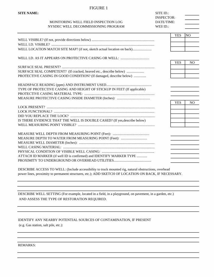
FIGURE 1SITE NAME: SITE ID.:
INSPECTOR:MONITORING WELL FIELD INSPECTION LOG DATE/TIME:
NYSDEC WELL DECOMMISSIONING PROGRAM WEll ID.:
YES NOWELL VISIBLE? (If not, provide directions below) ........................................................................ WELL I.D. VISIBLE? ...................................................................................................................... WELL LOCATION MATCH SITE MAP? (if not, sketch actual location on back)......................
WELL I.D. AS IT APPEARS ON PROTECTIVE CASING OR WELL: .................................YES NO
SURFACE SEAL PRESENT? ........................................................................................................... SURFACE SEAL COMPETENT? (If cracked, heaved etc., describe below) .................... PROTECTIVE CASING IN GOOD CONDITION? (If damaged, describe below) ..............
HEADSPACE READING (ppm) AND INSTRUMENT USED....................................................TYPE OF PROTECTIVE CASING AND HEIGHT OF STICKUP IN FEET (If applicable) PROTECTIVE CASING MATERIAL TYPE: .................................................................................MEASURE PROTECTIVE CASING INSIDE DIAMETER (Inches): ......................................
YES NOLOCK PRESENT? ............................................................................................................................ LOCK FUNCTIONAL? .................................................................................................................... DID YOU REPLACE THE LOCK? ................................................................................................. IS THERE EVIDENCE THAT THE WELL IS DOUBLE CASED? (If yes,describe below) WELL MEASURING POINT VISIBLE? ........................................................................................
MEASURE WELL DEPTH FROM MEASURING POINT (Feet): ..........................................MEASURE DEPTH TO WATER FROM MEASURING POINT (Feet): ..............................MEASURE WELL DIAMETER (Inches): .......................................................................................WELL CASING MATERIAL: .........................................................................................................PHYSICAL CONDITION OF VISIBLE WELL CASING: .............................................................ATTACH ID MARKER (if well ID is confirmed) and IDENTIFY MARKER TYPE ............PROXIMITY TO UNDERGROUND OR OVERHEAD UTILITIES...........................................
DESCRIBE ACCESS TO WELL: (Include accessibility to truck mounted rig, natural obstructions, overhead power lines, proximity to permanent structures, etc.); ADD SKETCH OF LOCATION ON BACK, IF NECESSARY.
DESCRIBE WELL SETTING (For example, located in a field, in a playground, on pavement, in a garden, etc.) AND ASSESS THE TYPE OF RESTORATION REQUIRED.
IDENTIFY ANY NEARBY POTENTIAL SOURCES OF CONTAMINATION, IF PRESENT (e.g. Gas station, salt pile, etc.):
REMARKS:

FIGURE 2
DECOMMISSIONING PROCEDURE SELECTION

FIGURE 3
WELL DECOMMISSIONING RECORD

FIGURE 3WELL DECOMMISSIONING RECORD
Site Name: Well I.D.:Site Location: Driller:Drilling Co.: Inspector:
Date:
DECOMMISSIONING DATA WELL SCHEMATIC*(Fill in all that apply) Depth
(feet)OVERDRILLINGInterval DrilledDrilling Method(s)Borehole Dia. (in.)Temporary Casing Installed? (y/n)Depth temporary casing installedCasing type/dia. (in.)Method of installing
CASING PULLINGMethod employedCasing retrieved (feet)Casing type/dia. (in)
CASING PERFORATINGEquipment usedNumber of perforations/footSize of perforationsInterval perforated
GROUTINGInterval grouted (FBLS)# of batches preparedFor each batch record:Quantity of water used (gal.)Quantity of cement used (lbs.)Cement typeQuantity of bentonite used (lbs.)Quantity of calcium chloride used (lbs.)Volume of grout prepared (gal.)Volume of grout used (gal.)
COMMENTS: * Sketch in all relevant decommissioning data, including:
interval overdrilled, interval grouted, casing left in hole,
well stickup, etc.
Drilling Contractor Department Representative
APPENDIX A - REPORTS APPENDIX A1 - INSPECTOR’S DAILY REPORT APPENDIX A2 - PROBLEM IDENTIFICATION REPORT APPENDIX A3 - CORRECTIVE MEASURES REPORT

[Page Intentionally Left Blank]
Inspector’s Daily Report
CONTRACTOR:ADDRESS:
TELEPHONE:
LOCATION
WEATHER TEMP
FROM TO
A.M. P.M. DATE
CONTRACTOR’S WORK FORCE AND EQUIPMENT
DESCRIPTION DESCRIPTION DESCRIPTION DESCRIPTIONH # H # H # H #
Field Engineer
Superintendent
Laborer Foreman
Laborer
Operating Engineer
Carpenter
Ironworker
Carpenter
Concrete Finisher
Equipment
Generators
Welding Equip.
Paving Equip. & Roller
Air compressor
Front Loader Ton
Bulldozer
Backhoe
SEE REVERSE SIDE FOR SKETCH YES NO
WORK PERFORMED:
PAY ITEMS
CONTRACT STA
DESCRIPTION QUANTITY REMARKSNumber ITEM FROM TO
TEST PERFORMED:
PICTURES TAKEN:
VISITORS:
QA PERSONNEL
SIGNATURE
REPORT NUMBER
SHEET Of
Appendix A1

[Page Intentionally Left Blank]

PROBLEM IDENTIFICATION REPORT
Project
Contractor
Subject
Job Number
Date
Day
Sky/Precip.
TEMP.
WIND
HUMIDITY
PROBLEM DESCRIPTION Reference Daily Report Number 1:
PROBLEM LOCATION - REFERENCE TEST RESULTS AND LOCATION (Note: Use sketches on back of form as appropriate):
PROBABLE CAUSES:
SUGGESTED CORRECTIVE MEASURES:
APPROVALS:
QA ENGINEER:
PROJECT MANAGER:
Distribution:
QA Personnel
Signature:
1. Project Manager2. Field Office3. File4. Owner
Su M T W Th F Sa
ClearPartlyCloudy
Cloudy Rainy Snow
<32F 32-40F 40-70F 70-80F 80-90F
No Light Strong
Dry Mod. Humid
Appendix A2 (Page 1 of 2)

MEETINGS HELD AND RESULTS
REMARKS
REFERENCES TO OTHER FORMS
SKETCHES
SAMPLE LOG
SAMPLE NUMBER
APPROXIMATE LOCATION OF STOCKPILE
NUMBER OF STOCKPILE
DATE OF COLLECTION
CLIMATIC CONDITIONS
FIELD OBSERVATION
SHEETS OF
Appendix A2 (Page 2 of 2)

CORRECTIVE MEASURES REPORT
Project
Contractor
Subject
Job Number
Date
Day
Sky/Precip.
TEMP.
WIND
HUMIDITY
CORRECTIVE MEASURES TAKEN (Reference Problem Identification Report No.):
RETESTING LOCATION:
SUGGESTED METHOD OF MINIMIZING RE-OCCURRENCE:
SUGGESTED CORRECTIVE MEASURES:
APPROVALS:
QA ENGINEER:
PROJECT MANAGER:
Distribution:
QA Personnel
Signature:
1. Project Manager2. Field Office3. File4. Owner
Su M T W Th F Sa
ClearPartlyCloudy
Cloudy Rainy Snow
<32F 32-40F 40-70F 70-80F 80-90F
No Light Strong
Dry Mod. Humid
Appendix A3