pipe selection for water and sewer projects
TRANSCRIPT

Pipe Selection for Water and Sewer Projects
Pipe Selection for Water and Sewer
Projects
By
Pete Peterson, PE
PDHLibrary Course No 2020021 6 PDH HOURS

2 Pipe Selection for Water and Sewer Projects | www.pdhlibrary.com
PIPE SELECTION FOR WATER AND SEWER PROJECTS
There are over one million miles of water distribution and transmission main and another one million miles of sewer main in place in the United States. One of the key components of design of water and sewer pipeline projects is the selection of pipe. This design decision is often overlooked because we use the pipes that we�ve always used in the past. Almost
every municipality and water or sewer agency has a short list of standard pipes that are acceptable for pressure and gravity applications. These lists were often developed many years ago and may not represent the current state of the practice. The primary purpose of this course is to describe the different pipe materials that are available for use in both pressure and gravity applications. An understanding of the options allows engineers and managers to make decisions which will result in better designs that are more cost effective. Selecting a pipe material because �that�s what
we�ve always done� often results in a pipe that is either over-designed or under-designed and often eliminates competition. When more than one pipe material is allowed, suppliers and contractors are forced to be more competitive, which yields a satisfactory project at a lower price. PRESSURE PIPES Pressure pipes are most often used for water mains, both transmission and distribution
mains. In many applications it is necessary to transport potable water and pipes used for this
purpose must usually meet standards developed by the American Water Works Association
(AWWA) or the National Sanitation Foundation (NSF). The most common materials for
transmission mains (generally larger pipes) are ductile iron and welded steel. The most
common materials for distribution mains (generally smaller pipes) are ductile iron and PVC.
It is not always obvious in looking at a pipe what the pressure rating for the pipe might be.
However, most pipe has a stamp on the outside of the pipe that identifies the specific design
parameters for each piece of pipe. Many of the photographs in this course include this label
for reference. This aids the design engineer, owner and resident project representative in
determining that the material on site meets the required specification.
Ductile Iron/Cast Iron Pipe
Cast iron pipe has been widely available since the turn of the 20th century and was
commercially available for pressure pipes until about 1990. Manufacturing processes have
improved significantly and cast iron pipe has been replaced by ductile iron pipe which is
stronger. Ductile iron pipe has been available since the 1960s. However, many water
systems have a significant amount of pipe that has been in place since before 1960 so a lot
of cast iron pipe is still in use. Old cast iron pipe has a much thicker wall than current ductile
iron pipe � for example, 36-inch diameter cast iron pipe constructed in 1952 for a 150 psi
pressure rating had a wall thickness of 1.22 inches, and the same size and pressure class
ductile iron pipe currently has a wall thickness of 0.38 inches. Ductile iron pipe is generally
3 Pipe Selection for Water and Sewer Projects | www.pdhlibrary.com
available in sizes from 3-inch diameter to 64-inch diameter. However, the local availability of
pipe sizes varies so it is important to check with the manufacturer�s representative to find out
what sizes are readily available in any locality.
The most common specifications that cover ductile iron pressure pipe include:
AWWA C104/A21.4 Cement-Mortar Lining for Ductile Iron Pipe and Fittings AWWA C105/A21.5 Polyethylene Encasement for Ductile-Iron Pipe Systems AWWA C110 Ductile-Iron and Gray-Iron Fittings AWWA C111/A21.11 Rubber-Gasket Joints for Ductile-Iron Pressure Pipe and
Fittings AWWA C115 Flanged Ductile-Iron Pipe with Ductile-Iron or Gray-Iron Threaded
Flanges AWWA C116 Protective Fusion-Bonded Coatings for the Interior and Exterior
Surfaces of Ductile-Iron and Gray-Iron Fittings AWWA C150 Thickness Design of Ductile-Iron Pipe AWWA C151/A21.51 Ductile-Iron Pipe, Centrifugally Cast AWWA C600 Installation of Ductile-Iron Mains and Their Appurtenances AWWA C606 Grooved and Shouldered Joints
Ductile iron pipe can often qualify as a recycled material for projects looking to meet specific
environmental certifications. Most ductile iron pipe manufactured in the United States uses
scrap iron as a primary source.
Ductile iron pipe usually has a cement mortar interior lining to reduce the potential for
corrosion of the interior of the pipe. This lining is subject to attack from soft, aggressive
waters. Ductile iron pipe is manufactured in two different thickness ratings � pressure class
pipe and special thickness class pipe. Pressure class pipe is manufactured to have a
pressure rating of 150, 200, 250, 300 or 350 psi. Only some pressure ratings are available
for smaller diameter pipe. For example, pressure class 350 is the only thickness available for
pipes 4-inch diameter up to 12-inch diameter. The outside diameter of all pressure class pipe
is the same, regardless of the class, so different pressure class pipe can be easily joined
together. The factor of safety for pressure class pipe varies, however. For example, 12-inch
diameter Class 350 pipe has a factor of safety of about 3.9, while 24-inch diameter Class
350 pipe has a factor of safety of about 3.2. All ductile iron pipe meeting AWWA standards
includes a surge pressure factor of 100 psi, so pipe rated at 350 psi is rated for 350 psi
working pressure plus 100 psi of surge pressure. The 100 psi surge pressure factor is based
on the pressure resultant from a sudden valve closure in a ductile iron pipeline where the
velocity is 2 feet per second. Actual surge pressures may be greater than or less than 100
psi, depending on the system.
Ductile iron pipe is also made in special thickness class (see Figure 1). The availability of
special thickness class varies in different parts of the country, but it is made in classes 50,
51, 52, 53, 54, 55 and 56. Most municipalities that use special thickness class have a

4 Pipe Selection for Water and Sewer Projects | www.pdhlibrary.com
standard thickness that is used, often Class 52 or Class 53. While pressure class ductile iron
pipe has a consistent pressure rating regardless of diameter, the same is not true for special
thickness class pipe. If the same safety factor is used for both pipes, a 12-inch diameter
Class 52 pipe would have a pressure rating of 530 psi, while a 24-inch diameter Class 52
pipe would have a pressure rating of 330 psi. In 48-inch diameter, Class 52 pipe would have
a pressure rating of about 300 psi. The outside diameter for all classes of special thickness
class ductile iron pipe is the same for each nominal diameter, and it is also the same as the
outside diameter for all pressure class pipe, so all ductile iron pipe is compatible based on
diameter.
Figure 1 � Class 51 Ductile Iron Pipe
The exterior of ductile iron pipe is subject to corrosion especially in corrosive soils. The use
of polyethylene encasement around the outside of the pipe is standard procedure in many
jurisdictions. The polyethylene encasement generally provides adequate protection against
exterior corrosion (see Figure 2).

5 Pipe Selection for Water and Sewer Projects | www.pdhlibrary.com
Figure 2 � Polyethylene encasement for ductile iron pipe
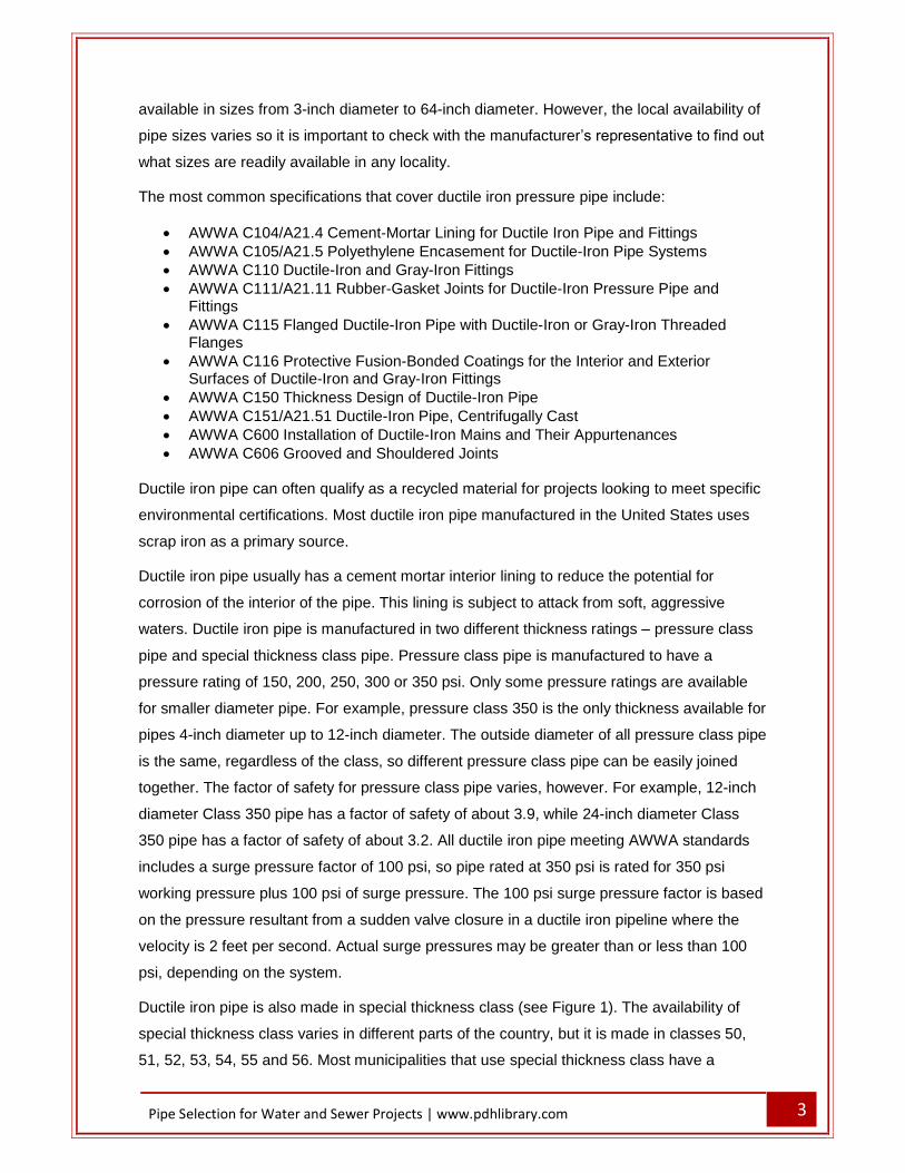
Poly Vinyl Chloride (PVC) Pipe
PVC pipe used for municipal water mains is usually specified to meet the requirements of
AWWA standard C900 (see Figure 3). This standard now covers all PVC pipe from 4-inch
diameter to 60-inch diameter. In most sizes, it is available in three different wall thickness,
defined by the Dimension Ratio (DR). These are DR 14, DR 18 and DR 25. The DR of a
PVC pipe is determined by dividing the outside diameter by the wall thickness. For example,
12-inch DR 25 pipe has an outside diameter of 13.2 inches and a wall thickness of 0.528
inches. The dimension ratio is calculated as 13.2/0.528 = 25.0. DR 14 pipe has a pressure
rating of 305 psi, DR 18 a pressure rating of 235 psi and DR 25 a pressure rating of 165 psi.
DR 14 PVC is generally only available up to 16 inches in diameter.
6 Pipe Selection for Water and Sewer Projects | www.pdhlibrary.com
Figure 3 � PVC Pressure Pipe
Earlier versions of AWWA C900 provided different pressure ratings for this pipe. The original
standard classified DR 25 with a pressure rating of 100 psi, DR 18 with a pressure rating of
150 psi and DR 14 with a pressure rating of 200 psi. Older record drawings may refer to this
pipe by the pressure rating. The difference between the old pressure rating and the current
pressure rating is a function of how the pipe is rated, not a difference in the pipe. In the old
standard, the factor of safety was 2.5 and there was a surge pressure allowance of 35 psi. In
the current standard, the safety factor was reduced to 2.0 and the surge allowance was
eliminated.
This is not to imply that surge pressures are no longer a consideration in the design of a pipe
system, but rather it is now incumbent upon the designer to determine an acceptable surge
pressure. This surge pressure allowance was also based on a sudden valve closure in a
PVC pipeline where the velocity is 2 feet per second. The difference between this surge
pressure and the 100 psi surge pressure in ductile iron pipe is due to the difference in the
pipe materials (PVC is more flexible and resists the surge more effectively than ductile iron
pipe).
7 Pipe Selection for Water and Sewer Projects | www.pdhlibrary.com
PVC pipe is not affected by corrosion on either the interior of the pipe or the exterior of the
pipe, so additional corrosion protection is not necessary. The outside diameter of PVC C900
pipe is the same as the outside diameter of ductile iron pipe.
Some PVC pressure pipe is manufactured to meet the requirements of ASTM D2241 �
Standard Specification for Poly Vinyl Chloride (PVC) Pressure-Rated Pipe (SDR Series).
This pipe does not meet the standards of AWWA C900 but it does meet the requirements of
NSF 61 � Drinking Water System Components so some regulatory agencies will allow its
use for drinking water. The outside diameters of pipe meeting ASTM D2241 do not match
the outside diameters of pipe meeting AWWA C900, so a transition coupling is required at
any connection. This pipe is generally available in sizes from 4-inch diameter to 12-inch
diameter, and pressure ratings from 63 psi (SDR 64) to 250 psi (SDR 17). This pipe uses the
terminology SDR (Standard Dimension Ratio), but the SDR for this pipe is calculated in the
same manner as the DR for PVC pipe meeting AWWA C900. Similar to PVC pipe meeting
AWWA C900, pipe with a given SDR value has a consistent pressure rating, regardless of
diameter.
PVC pressure pipe is also available in Schedule 40 and Schedule 80 pipe meeting the
requirements of ASTM D1784. This pipe also meets the requirements of NSF 61 so it can be
used for drinking water in some locations. Schedule 40 pipe is available in sizes up to 16-
inches in diameter. The pressure rating for this pipe varies depending on pipe size. For
example, 6-inch diameter Schedule 40 PVC has a pressure rating of 180 psi, while 12-inch
diameter Schedule 40 PVC has a pressure rating of 130 psi. The outside diameter of pipe
meeting ASTM D1784 is also different than the outside diameter of either AWWA C900 pipe
or ASTM D2241 pipe, so a transition coupling is required at any connection.
High Density Polyethylene (HDPE) Pipe
The use of solid wall High-Density Polyethylene (HDPE) Pipe is not extremely common but it
is usually considered an acceptable material. HDPE pipe used for potable water applications
usually meets the requirements of the AWWA C906 standard. The primary advantage of
HDPE is that the joints are usually made by heat fusion, which bonds the two sections of
pipe together by melting a small part of each pipe. When this joint is made properly, it is as
strong as the rest of the pipe and is not as susceptible to failure and leakage as the standard
gasketed joints used for ductile iron and PVC pipe. HDPE is available is a wide variety of
diameters � from 4-inch to 63 inches, and a variety of pressure ratings, from 63 psi to 333
psi. Not all diameters are available in all pressure ratings, however. The pressure ratings for
HDPE pipe have changed in more recent editions of AWWA C906, based in part on changes
in the materials used to manufacture HDPE pipe. Some of the changes are also due to
8 Pipe Selection for Water and Sewer Projects | www.pdhlibrary.com
differences in safety factors as well. Before HDPE is specified for a project, the design
engineer should carefully evaluate the appropriate safety factors and design pressures. The
pressure rating for HDPE pipe does not include any allowance for surge pressures. Surge
pressures must be added to the maximum working pressure to establish the design pressure
for the pipe.
HDPE pipe can have an outside diameter that matches one of two different specifications.
Some HDPE pipe has an outside diameter that matches ductile iron pipe (DIPS). This pipe
has the same outside diameter as ductile iron pipe. However, other HDPE pipe has an
outside diameter that matches iron pipe sizes (IPS). In general, pipe that meets the IPS
classification will have a smaller outside diameter, and consequently a smaller inside
diameter, than pipe that meets the DIPS classification. In theory, both pipe diameter
classifications are available everywhere, but some in some areas, one classification is more
common than the other. Before specifying HDPE pipe for a project, a phone call to the local
pipe supplier could help in specifying the more common type in a particular area.
Because HDPE is not as strong as PVC, the wall thickness must be greater to match the
same pressure. For example, with 12-inch diameter PVC, to achieve a pressure rating of
235 psi, the dimension ratio has to be 18 and the wall thickness is about 0.73 inches. With
an outside diameter of 13.2 inches, the inside diameter is about 11.7 inches. For 12-inch
HDPE to achieve a pressure rating of 250 psi (the closest to the 235 psi rating of PVC), the
dimension ratio has to be 9. For pipe meeting DIPS standards, the outside diameter is 13.2
inches (the same as ductile iron and C900 PVC), but the wall thickness is about 1.5 inches.
This means that the inside diameter is only about 10.2 inches, which is substantially smaller
than the same nominal diameter PVC pipe. For pipe meeting IPS standards, the outside
diameter of DR 9 HDPE is 12.75 inches and the wall thickness is about 1.4 inches, so the
inside diameter is about 9.9 inches. When designing with HDPE pipe, it is necessary to be
aware of the substantial differences in inside diameter and consider the hydraulic impacts of
this difference before selecting the nominal pipe diameter. It is inappropriate to assume that
12-inch nominal diameter HDPE is hydraulically equivalent to 12-inch nominal diameter
PVC.
HDPE pipe is most commonly used in water systems where it is necessary or desirable to
use trenchless techniques to install the pipe. This includes straight borings across major
roadways and directional drilling across water bodies (including rivers, streams, lakes and
wetlands) to avoid impacts to the surface. It is acceptable in other locations and can be used
in typical open-trench construction, but it is not commonly used in this application.
Smooth Steel Pipe
9 Pipe Selection for Water and Sewer Projects | www.pdhlibrary.com
Steel pipe has been widely available since the turn of the 20th century and is still in common
use. The most common specifications that cover steel pressure pipe include:
AWWA C200 Steel Water Pipe, 6 In. (150 mm) and Larger AWWA C203 Coal-Tar Protective Coatings and Linings for Steel Water Pipes AWWA C205 Cement�Mortar Protective Lining and Coating for Steel Water Pipe 4
In. (100 mm) and Larger�Shop Applied AWWA C206 Field Welding of Steel Water Pipe AWWA C208 Dimensions for Fabricated Steel Water Pipe Fittings AWWA C207 Steel Pipe Flanges for Waterworks Service�Sizes 4 In. Through 144
In. (100 mm Through 3,600 mm) AWWA C210 Liquid-Epoxy Coatings and Linings for Steel Water Pipe and Fittings AWWA C213 Fusion-Bonded Epoxy Coatings and Linings for Steel Water Pipe and
Fittings AWWA C214 Tape Coatings for Steel Water Pipe AWWA C216 Heat-Shrinkable Cross-Linked Polyolefin Coatings for Steel Water Pipe
and Fittings AWWA C217 Microcrystalline Wax and Petrolatum Tape Coating Systems for Steel
Water Pipe and Fittings AWWA C218 Liquid Coatings for Aboveground Steel Water Pipe and Fittings AWWA C219 Bolted Sleeve-Type Couplings for Plain-End Pipe AWWA C220 Standard for Stainless-Steel Pipe, 1/2 In. (13 mm) and Larger AWWA C221 Fabricated Steel Mechanical Slip-Type AWWA C222 Polyurethane Coatings and Linings for Steel Water Pipe and Fittings AWWA C223 Fabricated Steel and Stainless Steel Tapping Sleeves AWWA C224 Nylon-11-Based Polyamide Coatings and Linings for Steel Water Pipe
and Fittings AWWA C225 Fused Polyolefin Coatings for Steel Water Pipe AWWA C226 Stainless-Steel Fittings for Waterworks Service, Sizes 1/2 In. Through
72 In. (13 mm Through 1,800 mm) AWWA C227 Bolted, Split-Sleeve Couplings AWWA C228 Stainless-Steel Pipe Flange Joints for Water Service�Sizes 2 In.
Through 72 In. (50 mm Through 1,800 mm) AWWA C229 Fusion-Bonded Polyethylene Coatings for Steel Water Pipe and
Fittings AWWA C230 Stainless-Steel Full-Encirclement Repair and Service Connection
Clamps for 2 in. Through 12 in. (50 mm Through 300 mm) Pipe AWWA C231 Field Welding of Stainless Steel Water Pipe AWWA C602 Cement-Mortar Lining of Water Pipelines in Place - 4 In. (100 mm) and
Larger Steel pipe is available in a larger variety of diameters, up to at least 120-inches, due to the
way the pipe is manufactured. It is also available in custom diameters. The thickness design
for steel pipe typically comes from AWWA Design Manual M11. It uses the Barlow formula:
t = (p*d)/(2*s)
where
t = minimum pipe wall thickness, inches
p = internal design pressure, psi
10 Pipe Selection for Water and Sewer Projects | www.pdhlibrary.com
d = outside diameter of pipe, inches
s = allowable design stress, psi
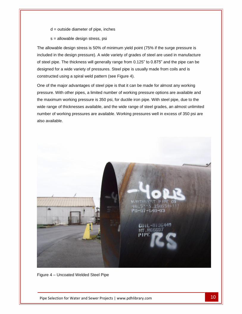
The allowable design stress is 50% of minimum yield point (75% if the surge pressure is
included in the design pressure). A wide variety of grades of steel are used in manufacture
of steel pipe. The thickness will generally range from 0.125� to 0.875� and the pipe can be
designed for a wide variety of pressures. Steel pipe is usually made from coils and is
constructed using a spiral weld pattern (see Figure 4).
One of the major advantages of steel pipe is that it can be made for almost any working
pressure. With other pipes, a limited number of working pressure options are available and
the maximum working pressure is 350 psi, for ductile iron pipe. With steel pipe, due to the
wide range of thicknesses available, and the wide range of steel grades, an almost unlimited
number of working pressures are available. Working pressures well in excess of 350 psi are
also available.
Figure 4 � Uncoated Welded Steel Pipe

11 Pipe Selection for Water and Sewer Projects | www.pdhlibrary.com
Steel pipe is very subject to corrosion, therefore both the inside and outside of the pipe must
be protected from corrosion. The most common interior coating is a cement-mortar lining,
essentially identical to what is used for ductile iron pipe. This lining is subject to attack from
soft, aggressive waters. Interior linings also include epoxies and polyurethanes. They both
provide excellent water and chemical resistance properties. They are a better choice in
situations with high velocities and aggressive environments. Surface preparation is critical,
so these lining are almost always applied in the factory. The epoxies are applied by an
airless spray and cure in hours. The polyurethanes require heated, plural component
equipment and they cure in minutes.
The most common exterior coating is a tape coating (see Figure 5). The tape coating
process consists of cleaning and blasting the pipe surface, applying a primer-adhesive, then
simultaneously applying and inner dielectric tape (for corrosion protection) and one or more
layers of outer tape (for mechanical protection). Epoxies and polyurethanes can also be
used for the exterior of the pipe, with the same properties as the linings used for the interior
of the pipe (see Figure 6).
Figure 5 � Tape coating for steel pipe
12 Pipe Selection for Water and Sewer Projects | www.pdhlibrary.com
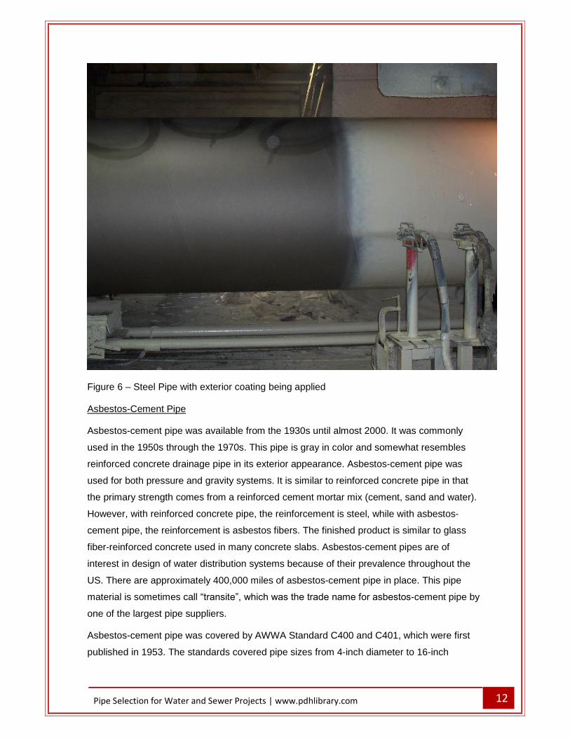
Figure 6 � Steel Pipe with exterior coating being applied
Asbestos-Cement Pipe
Asbestos-cement pipe was available from the 1930s until almost 2000. It was commonly
used in the 1950s through the 1970s. This pipe is gray in color and somewhat resembles
reinforced concrete drainage pipe in its exterior appearance. Asbestos-cement pipe was
used for both pressure and gravity systems. It is similar to reinforced concrete pipe in that
the primary strength comes from a reinforced cement mortar mix (cement, sand and water).
However, with reinforced concrete pipe, the reinforcement is steel, while with asbestos-
cement pipe, the reinforcement is asbestos fibers. The finished product is similar to glass
fiber-reinforced concrete used in many concrete slabs. Asbestos-cement pipes are of
interest in design of water distribution systems because of their prevalence throughout the
US. There are approximately 400,000 miles of asbestos-cement pipe in place. This pipe
material is sometimes call �transite�, which was the trade name for asbestos-cement pipe by
one of the largest pipe suppliers.
Asbestos-cement pipe was covered by AWWA Standard C400 and C401, which were first
published in 1953. The standards covered pipe sizes from 4-inch diameter to 16-inch

13 Pipe Selection for Water and Sewer Projects | www.pdhlibrary.com
diameter. The last version of AWWA C401 was published in 2001 and it has now been
withdrawn from use.
When these pipes are cut to make a new connection or to make a repair, or removed as part
of a replacement project, it is necessary to follow all regulations regarding cutting and
disposal of asbestos products. When the pipe is cut or broken, some of the asbestos fibers
become airborne and are very hazardous. These pipes can also be an issue when the
quality of the finished water changes, such as a change from a ground water source to a
surface water source. In soft or aggressive waters, the cement mortar can start to be
dissolved, which releases the asbestos fibers. Asbestos fibers are not extremely toxic in
water, but the release of the asbestos fibers starts to compromise the integrity of the pipe
which can result in small leaks or major breaks.
Pipe Joints
A number of different types of joints are available to connect one section of pipe to the
adjacent section. Joints in a pipe are typically the weakest point. They are also the most
common location of leakage, as well as the most common location for mechanical failure.
Ductile Iron Pipe Joints
There are three types of joints that are typically used with ductile iron pipe � push on joints
(Figure 7), flanged joints (Figures 8 and 9), and mechanical joints (Figure 10). The push on
joint is easily assembled and therefore is the most common type of joint used in
underground applications. The joint includes a bell on one end of the pipe, with a gasket in
the bell. The other end is a spigot, or plain end, which gets inserted into the bell. It is
important that both ends of the pipe be properly cleaned and that the gasket be provided
with an appropriate lubricant. The push on joint will allow a limited amount of deflection after
the joint is completed. The amount of deflection varies with size but is generally in the range
of about 3 degrees. Deflection at the joint can be an important aspect of a joint for water
mains that are installed in streets with a curvilinear design. By deflecting each joint slightly,
the pipe can approximately follow the street alignment, reducing or eliminating the need for
numerous bend fittings. The push on joint is an unrestrained joint and does not resist any
thrust forces at fittings.

14 Pipe Selection for Water and Sewer Projects | www.pdhlibrary.com
Figure 7 � Ductile Iron pipe with push-on joints
The flanged joint (Figures 8 and 9) is not usually used in underground applications. Each
end of the pipe has a flange installed. In Figure 8, it can be seen that the flange is screwed
on to the pipe section. The joint is assembled by installing a gasket between the flanges on
each pipe, and then bolts are installed. This creates a very strong joint that will transfer
thrust forces across the joint. It is not a flexible joint however, and no deflection, or change in
horizontal or vertical alignment, is possible with this joint. This joint is often used inside
buildings, such as treatment plants and pump stations, because of its strength and
resistance to thrust forces.

15 Pipe Selection for Water and Sewer Projects | www.pdhlibrary.com
Figure 8 � Flanged Ductile Iron Pipe

16 Pipe Selection for Water and Sewer Projects | www.pdhlibrary.com
Figure 9 � Flanged Ductile Iron Pipe Spool
The mechanical joint (Figure 10) is to some extent a combination of a push on joint and a
flanged joint. A mechanical joint consists of a flange with bolt holes, but the flange is not as
wide as the flange for flanged pipe. The flange on the fitting is cast as part of the fitting.
Immediately adjacent to the flange is a space for a gasket similar to the gasket used for a
push on joint. In order to assemble the joint, it is first necessary to properly clean all of the
pieces. A follower ring is then placed on the plain end of the pipe, and then the gasket is
placed on the plain end of the pipe. The plain end is then inserted into the mechanical joint
fitting. The gasket is slid into the fitting, and the follower ring slid next to the gasket. Tee
bolts are then installed in the bolt holes and the nuts tightened. This brings the gasket tight
into the fitting and the follower ring tight against the gasket, which completes the water-tight
joint capable of withstanding the stated design pressure. This joint is somewhat flexible in
that some deflection of the joint can be provided � usually between one and three degrees,
depending on the size of the pipe. The standard mechanical joint is not a restrained joint,

17 Pipe Selection for Water and Sewer Projects | www.pdhlibrary.com
however, as the only thing keeping the pipe from sliding out of the fitting is the friction of the
gasket against the pipe. Mechanical joint fittings are very commonly used in underground
installations.
Figure 10 � Ductile Iron Pipe with Mechanical Joints
It is possible to make the mechanical joint a restrained joint by the addition of what is
essentially a second follower ring. There are a number of different manufacturers of these
types of devices including Mega-Lug® and StarGrip®. An example is shown in Figure 11.
These devices include a second follower ring that is installed similar to the first follower ring,
and then a series of set screws (the blue screws in Figure 11) that are tightened and grip the
pipe wall, preventing the joint from pulling apart. The set screws push wedges into the pipe
wall, which then resist movement of the joint.

18 Pipe Selection for Water and Sewer Projects | www.pdhlibrary.com
Figure 11 � Joint restraint for mechanical joint fitting
PVC Pipe Joints
PVC pipe joints are typically push on joints, similar to those for ductile iron (see Figure 3).
The bell end of the pipe is provided with a pre-installed gasket and the spigot end of the pipe
is slightly beveled to aid in installation. As with ductile iron pipe, it is important that both ends
of the pipe be properly cleaned and that the gasket be provided with an appropriate
lubricant. The push on joint will allow a limited amount of deflection after the joint is
completed. The amount of deflection is about 2 degrees for pipe less than 12-inches in
diameter and 1.5 degrees for pipes larger than 12-inches in diameter.
PVC pipe that meets the requirements of ASTM D1784 typically has solvent weld joints.
Depending on pipe size, each pipe section might have a bell on one end and a plain pipe on
the other end, or it might have plain ends on both sides and be connected by use of a
coupling. To make the connection, both the bell and the plain end are carefully cleaned, first
with a cloth and then with a special cleaner. Both ends are then primed with a special primer.
Solvent (glue) is applied to the plain end and inserted into the bell, then rotated one quarter

19 Pipe Selection for Water and Sewer Projects | www.pdhlibrary.com
turn. The cleaner, primer and solvent all soften (or melt) the exterior of the pipe and bell.
When the joint dries (usually in a minute or so), the softened portions of the pipe and bell
fuse together, forming a water tight, pressure capable connection. Proper construction of a
solvent weld joint requires care on the part of the installers. If the joint is not properly
cleaned, it is likely to leak. In addition, too much solvent is as much of a problem as too little.
If too much solvent is used, the solvent will soften too much of the pipe and create a weak
spot which can fail prematurely.
Another option for joints with PVC pipe is a heat-weld joint (similar to that used for HDPE
pipe). Two plain ends of pipes are carefully cut to be precisely square, the ends are heated
and then pushed together to form a continuous joint. If the joint is made properly, the joint is
stronger than the pipe itself. This process is a proprietary process, which can create some
issues on public projects where proprietary items are difficult or impossible to specify.
HDPE Pipe Joints
Solid wall HDPE is typically connected using a heat-weld joint. Two plain ends of pipes are
carefully cut to be precisely square, the ends are heated and then pushed together to form a
continuous joint. If the joint is made properly, the joint is stronger than the pipe itself. This
process for HDPE pipe is not a proprietary process. Fittings for HDPE pipe are often made
using the same HDPE material and the joints are made in the same way. With this type of
joint, there is not connection that can be pulled apart by thrust forces, so the pipe is
considered to be continuously restrained.
Steel Pipe Joints
There are a variety of joint types available for steel pipe. Figures 12 and 13 show schematics
of most of the joint types available. One somewhat surprising joint option for many people is
the O-ring gasket joint. This joint is very similar to the push-on joint for ductile iron pipe and
PVC pipe. Steel pipe is most commonly available in pipe lengths of 40 feet, which is about
twice as long as the pipe joints for ductile iron and PVC. Consequently, there are fewer joints
in a segment of steel pipe, which can correspond to faster installation and fewer potential
locations for leaks. When welded joints are used, specialized welders are required, and
these individuals can be difficult to find in more remote locations.

20 Pipe Selection for Water and Sewer Projects | www.pdhlibrary.com
Figure 12 � Steel pipe butt welded joints

21 Pipe Selection for Water and Sewer Projects | www.pdhlibrary.com
Figure 13 � Other steel pipe joints
Pipe Fittings
A number of different pipe fittings are commonly used for water pipes. Fittings are used at
changes in direction and where pipes come together. The most common bends are 90-
degrees, 45-degrees, 22.5-degrees and 11.25-degrees. Where pipes come together, tees
and crosses are used. When the main line (the run of the tee) is different than the branch
line, it may be possible to get a standard tee with the different size branch. For example, a
12-inch by 8-inch tee will have 12-inch diameter connections on both sides of the run and an

22 Pipe Selection for Water and Sewer Projects | www.pdhlibrary.com
8-inch diameter connection on the branch. Not all branch sizes are available with all run
sizes. For example, an 18-inch by 6-inch tee is not common. While it may be noted in the
manufacturer�s catalog or on their web site, it may not be readily available. It is also
advisable to contact the local pipe supplier to verify what sizes are readily available. When it
is necessary to change pipe sizes, at a fitting or along the pipe run, a reducer can be used to
accommodate the change in pipe size. In most situations, the fittings are constructed using
ductile iron and can be used with ductile iron and PVC pipes. Figure 14 shows a schematic
of a tee with ductile iron pipe extending from the branch of the tee, PVC pipe meeting
AWWA C900 requirements extending to the right of the tee, and PVC pipe meeting ASTM
D2241 requirements extending to the left of the tee.
When HDPE pipe is used, the number of fittings is significantly reduced. Valves will still be a
special installation but bends and tees are factory constructed using the same material and
these fittings are heat-welded to the pipe in the same way that sections are pipe are joined
together. Because the bends are factory-built out of the same material, any bend angle can
be created. It is not necessary to limit bend angles to those noted for ductile iron fittings.
When steel pipe is used, the number of fittings may also significantly reduced. If all of the
joints are welded, then the previous discussion about HDPE fittings also applies to steel
fittings. If the joints are o-ring gasket joints, then the fittings may also have gasket joints. In
this case, the fittings are not welded to the pipe, but the choice of bend angles remains
essentially unlimited because each fitting is factory built.

23 Pipe Selection for Water and Sewer Projects | www.pdhlibrary.com
Figure 14 � Mechanical Joint Ductile Iron Tee with three pipe materials
Thrust Forces
Due to the nature of the typical push-on joint used for water mains, where there are fittings in
the system, such as bends, tees, reducers, plugs or valves, there are often unbalanced
forces that need to be resisted. Historically, these forces have been resisted by the use of
thrust blocks, which are cast-in place concrete blocks placed adjacent to the fittings. In many
places, thrust blocks are being phased out in favor of restrained joints.
In order to determine the amount of restraint necessary, it is first necessary to determine the
thrust force. Figure 15 shows a schematic of a standard push on joint assembly. The
magnitude of the force on the joint is equal to PA, where P is the pressure (in pounds per
square inch, psi) and A is the cross-sectional area of the pipe (in square inches). Because of
the configuration of a standard joint with a gasket, the area used in the computation should
be calculated using the outside diameter of the pipe. For example, for a 12-inch diameter
PVC pipe meeting AWWA C900 standards, the outside diameter is 13.2 inches. If the
maximum pressure in the pipe is 100 psi, the thrust force is π*(13.2^2)/4 * 100 = 13,685
pounds. With the standard push on joint, there is a force acting in each direction on the joint,

24 Pipe Selection for Water and Sewer Projects | www.pdhlibrary.com
and the forces are equal in magnitude and opposite in direction, so the thrust force in
internally balanced.
Selection of the appropriate pressure for the thrust force calculation requires an
understanding of the specific application. The restraint system designed to resist the thrust
forces needs to be adequate to resist the maximum forces that could be expected at each
location. The forces are directly related to the pressure, so the maximum pressure will create
the maximum force at any location. The maximum pressure could be the result of several
possible situations. The maximum normal working pressure of the system could be the
maximum pressure. Depending on the system, surge pressures could be higher than the
maximum working pressure. If that is the case, then the maximum surge pressure should be
used in the thrust force calculation, rather than the maximum working pressure. The third
situation to consider in selecting the appropriate thrust restraint is the test pressure during
installation. In many situations, a new water main will be subjected to a test pressure that is
greater than the anticipated working pressure. In some cases, the test pressure is equal to
the rated pressure of the pipe. Any of these possible conditions could result in the maximum
thrust force.
Figure 15 � standard push on joint thrust forces
When a fitting such as a bend is used to change the direction of flow, the magnitude of the
forces remains equal, but the forces no longer act in exactly opposite directions. Therefore,
there is a resultant force, such as the force for a bend shown in Figure 16. The magnitude of
the resultant force is a function of pressure, pipe size and the degree of deflection (θ). The
direction of the resultant force is a function of the degree of deflection. To calculate the
resultant force, use:
F = 2 * P * A * (sin θ/2).
25 Pipe Selection for Water and Sewer Projects | www.pdhlibrary.com
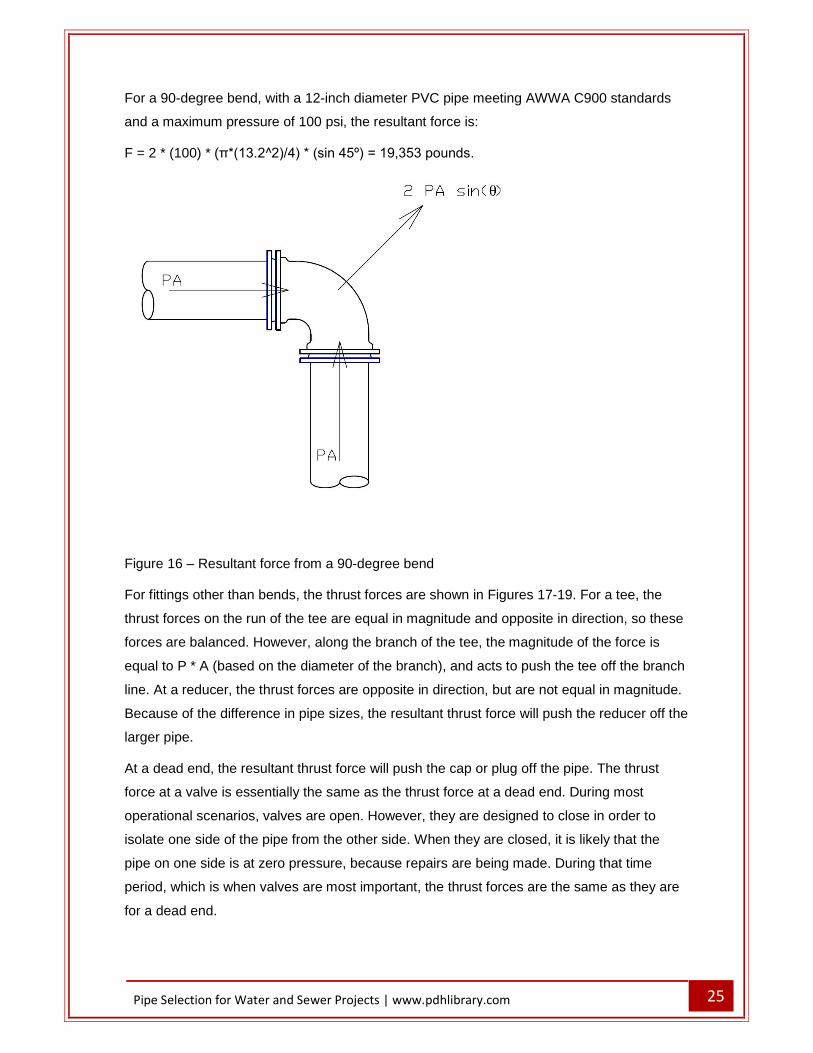
For a 90-degree bend, with a 12-inch diameter PVC pipe meeting AWWA C900 standards
and a maximum pressure of 100 psi, the resultant force is:
F = 2 * (100) * (π*(13.2^2)/4) * (sin 45º) = 19,353 pounds.
Figure 16 � Resultant force from a 90-degree bend
For fittings other than bends, the thrust forces are shown in Figures 17-19. For a tee, the
thrust forces on the run of the tee are equal in magnitude and opposite in direction, so these
forces are balanced. However, along the branch of the tee, the magnitude of the force is
equal to P * A (based on the diameter of the branch), and acts to push the tee off the branch
line. At a reducer, the thrust forces are opposite in direction, but are not equal in magnitude.
Because of the difference in pipe sizes, the resultant thrust force will push the reducer off the
larger pipe.
At a dead end, the resultant thrust force will push the cap or plug off the pipe. The thrust
force at a valve is essentially the same as the thrust force at a dead end. During most
operational scenarios, valves are open. However, they are designed to close in order to
isolate one side of the pipe from the other side. When they are closed, it is likely that the
pipe on one side is at zero pressure, because repairs are being made. During that time
period, which is when valves are most important, the thrust forces are the same as they are
for a dead end.

26 Pipe Selection for Water and Sewer Projects | www.pdhlibrary.com
Figure 17 � Resultant Force from Tee
Figure 18 � Resultant Force from Reducer
Figure 19 � Resultant Force from Dead End (or Valve)

27 Pipe Selection for Water and Sewer Projects | www.pdhlibrary.com
Thrust Restraint
Thrust Blocks
If the thrust forces that are developed at fittings are not adequately resisted, the joints at the
fittings will come apart. Push on joints and mechanical joints have no ability to resist these
forces. In order to resist these forces, some means of restraint is necessary. Historically,
concrete thrust blocks were used to resist these forces. Thrust blocks are cast-in-place after
the water line and fittings are installed. The thrust blocks need to extend from the fitting to
the undisturbed earth at the edge of the trench. The function of a thrust block is to transfer
the resultant force from the fitting to the adjacent soil, without allowing movement of the
fitting. The thrust block itself does not resist the forces. Only a small amount of resisting
force is provided by the weight of the concrete block. The primary resisting force is provided
by the in-place soils at the edge of the trench. The lateral bearing pressure of the soils, along
with the surface area of the thrust block pushing against these soils, will determine the
magnitude of the resisting force. Table 1 shows some representative examples of lateral
bearing pressures. Actual bearing pressures should be determined based on the in-place
soils.
Table 1
Typical Soil Bearing Pressures
Soil Type Typical Bearing Pressure, psf
Muck 0
Soft Clay 1000
Silt 1500
Sandy Silt 3000
Sand 4000
Sandy Clay 6000
Figure 20 shows schematics of thrust block details that are often included in standard
specifications and details. Note that dimension A is the width of the thrust block at the face of
the trench and dimension B is the height of the thrust block at the face of the trench. The
thrust blocks for the end plug, tee and bend clearly resist the thrust forces shown in Figures

28 Pipe Selection for Water and Sewer Projects | www.pdhlibrary.com
16, 17 and 19. The thrust block for the reducer does not directly resist the thrust forces
shown in Figure 18. The thrust block for the reducer relies in part on transferring the force to
the edge of the trench and in part on frictional resistance of the concrete sliding in the trench.
The schematics in Figure 20 also conveniently leave out the thrust block for a valve. While
the thrust forces are the same as for an end plug, a different thrust block is necessary. The
thrust block for a valve typically looks similar to the thrust block shown for a reducer.
However the concrete is not capable of transferring any of the force to the trench walls and
therefore must rely solely on frictional resistance. The use of these standard details should
be used with great care when reducers and valves are part of the project.
Figure 20 � Typical thrust block details
In conjunction with the typical details shown in Figure 20, dimensions for thrust blocks are
often shown in a standard table, such as that in Table 2. These tables are often included in
plan sets but the associated notes are sometimes omitted. The notes often include:
1. Tables are based on 150 psi main pressure 2. Tables are based on 2000 psf soil bearing pressure 3. Wrap all fitting with polyethylene 4. Thrust blocks shall be required at all fittings.
While these notes are important to proper design of the thrust block, it is not usually the
contractor�s responsibility to determine the appropriate design pressure or the soil bearing

29 Pipe Selection for Water and Sewer Projects | www.pdhlibrary.com
strength. These need to be determined by the design engineer, and the table adjusted as
necessary.
Table 2
Dimensions for Thrust Blocks
DIMENSIONS FOR THRUST BLOCKS
FITTING SIZE TEES & PLUGS 90° BEND 45° BEND REDUCERS
AND 22.5° BEND
A B A B A B A B
4� 1�-7� 1�-2� 1�-9� 1�-6� 1�-8� 0�-10� 1�-7� 0�-6�
6� 2�-0� 1�-11� 2�-5� 2�-2� 1�-10� 1�-7� 1�-9� 0�-10�
8� 2�-8� 2�-6� 3�-2� 3�-0� 2�-5� 2�-1� 1�-9� 1�-6�
10� 3�-4� 3�-3� 4�-0� 3�-10� 3�-0� 2�-9� 2�-2� 1�-11�
12� 4�-0� 3�-10� 4�-8� 4�-8� 3�-8� 3�-3� 2�-7� 2�-3�
14� 5�-5� 3�-10� 4�-11� 4�-11� 4�-9� 3�-5� 3�-5� 2�-5�
As an example of the size of thrust block necessary, assume the pipe in Figure 16 is a 12-
inch diameter ductile iron pipe meeting AWWA C151 and the maximum pressure is 100 psi.
As calculated previously, the resultant force is 19,353 pounds. The native soils in the trench
is sandy silt, with a lateral bearing capacity of 3000 pounds per square foot (psf). Thrust
blocks are typically designed with a safety factor of 1.5. The required bearing area of the
thrust block can be calculated by:
Area = Thrust Force * Safety Factor/Bearing Pressure
For this example then, the required area is
Area = 19,353 * 1.5 / 3000 = 9.7 square feet.
Figure 21 shows another example of a typical thrust block detail that is used. In this case,
the width of the thrust block equal to 4 times the pipe diameter. With a nominal 12-inch
diameter pipe, this would mean the thrust block would be 4 feet wide. In order to achieve a
bearing area of 9.7 square feet, the height of the thrust block at the edge of the trench would
need to be 9.7/4 = 2.43 feet or about 29.2 inches. The thrust block would be about 13 inches
high at the pipe (equal to the outside diameter), but the height would need to increase to 29
inches at the edge of the trench. Common construction of thrust blocks is that the height of

30 Pipe Selection for Water and Sewer Projects | www.pdhlibrary.com
the block doesn�t change. However, this would not provide adequate resistance to the thrust
forces in this example. It is possible to construct a thrust block to meet the thrust
requirements in this example, but it requires attention to detail during the design process and
especially during the construction process to ensure that adequate bearing area is provided.
In addition, as pipes get larger, the size of the thrust block gets correspondingly larger.
Figure 21 � Example Thrust Block for 90º Bend
There are a couple other issues associated with thrust blocks. With smaller diameter pipes,
the volume of concrete in a thrust block is relatively small. In order to more effectively utilize
the concrete in a typical concrete truck, numerous thrust blocks must be poured at the same
time. In addition, the concrete used in a thrust block must be allowed to cure long enough
that the compaction effort associated with backfill over the thrust block will not damage the
thrust block. Both of these issues result in the trench being open longer, which results in
more inconvenience to the traveling public.
Restrained Joints
As an alternative to thrust blocks, it is possible to use restrained joints on each pipe section.
A restrained joint makes a mechanical connection between the pipe and fitting, or between
two pieces of pipe, that makes it very difficult for the joint to come apart. A standard push on
joint or mechanical joint only stays in place due to the friction between the gasket and the

31 Pipe Selection for Water and Sewer Projects | www.pdhlibrary.com
pipe. Where there are no unbalanced forces, this friction is adequate to maintain a watertight
joint. However, where there are unbalanced forces, a push on joint or a mechanical joint is
not adequate to resist these unbalanced forces.
There are a number of proprietary products that are available to create a restrained joint.
There are three basic approaches to restraining a pipe joint. They include:
A gasket that has stainless steel wedges that embed into the spigot end of the pipe if there are forces that would cause the joint to separate. Examples of these products include MJ Field Lok® by US Pipe and Diamond Lok-21® by Diamond Plastics.
For pipes and fitting with mechanical joints, a second follower ring can be used. This second follower ring is connected to the first follower ring using bolt extensions, and then has set screws that are embedded into the spigot end of the pipe. These set screws resist the forces that would cause the joint to separate (see Figure 11 for an example). Examples of these products include Mega-Lug® by EBAA Iron and
Stargrip® by Star Pipe Products. A restrained joint harness can be attached to each side of the joint. This harness has
a ring (similar to a follower ring on a mechanical joint) that attaches to the pipe on each side. This ring has set screws that embed into the pipe. The rings on each side of the joint are connected with bolts. Examples of these products include Romac 600 Series Pipe Restraint and EBAA Iron 1900 Split Serrated Restraint Harness.
A restrained joint prevents movement of the two pieces that are connected, but the entire
assembly can still move. When a bend is connected to a single section of pipe, for example,
the resultant thrust force could still be greater than the resisting forces. There are two
primary resisting forces. The first is friction. In order for the bend in Figure 16 to move in the
direction of the thrust force, the fitting must move. If the fitting is connected to the adjacent
pipe, then the adjacent pipe must also move or slide. In order for the adjacent pipe to slide, it
is necessary for the thrust force to overcome the frictional resistance between the soil and
the pipe. The second resisting force is the passive soil resistance. Again referring to the
bend in Figure 16, in order for the bend to move in the direction of the thrust force, the bend
has to move out of square alignment with the adjacent pipe. The longer the lengths of pipe
that are mechanically connected to the fitting, the more resisting forces are available to keep
the fitting in place.

32 Pipe Selection for Water and Sewer Projects | www.pdhlibrary.com
The resisting force (F) for a bend is calculated by the equation:
F = [Ff + ½ Rs] * L * cos (θ/2)
where
Ff is the Unit Frictional Force
Rs is the Unit Bearing Resistance
L is length of Restrained Joint Pipe required
θ is the angle of the bend
The frictional resistance (Fs) is calculated by the following equation:
Fs = Ap * C + W tan δ
where
Ap = surface area of the pipe bearing on the soil
C = Pipe cohesion, fc * Cs
Cs = soil cohesion
fc and fФ are coefficients related to soil types and pipe material
δ = Pipe friction angle, fФ * Ф
Ф = internal friction angle of the soil
W = unit normal force
Ap = π D/2 (for bends, assume ½ the pipe circumference bears against the
soil)
The bearing resistance is calculated by the following equation:
Rs = Kn Pp D�
where
Rs is unit bearing resistance
Kn is an empirical coefficient that is a function of compaction in the trench,
backfill material and the undisturbed earth
D� is pipe outside diameter

33 Pipe Selection for Water and Sewer Projects | www.pdhlibrary.com
Pp is passive soil pressure
The passive soil pressure is calculated by the following equation:
Pp = γ Hc NФ + 2 Cs (NФ)0.5
where
Pp = passive soil pressure (psf)
γ = backfill soil density (pcf)
Hc = mean depth from surface to plane of resistance, in feet (centerline of a pipe or
center of bearing area of a thrust block)
Cs = soil cohesion (psf)
NФ = tan2 (45° + Ф/2)
Ф = internal friction angle of the soil
While these calculations can be completed by hand, there are two software packages
available that will easily calculate the length of restrained pipe necessary to resist the
resultant thrust force. One on-line calculator is available on the EBAA Iron web site. The
other on-line calculator is available on the DIPRA (Ductile Iron Pipe Research Association)
web site. Either of these calculators can be used to quickly estimate the length of restrained
joint pipe necessary for a specific application. The use of restrained joints can eliminate the
need for thrust blocks and speed up the installation process. However, the components of
the devices used to restrain joint are generally made of iron and steel and thus are subject to
corrosion. The recommendation for corrosion resistance for these devices is to double wrap
them using standard polyethylene encasement. In more corrosive soils, use of more positive
corrosion resistance, such as sacrificial anodes, is recommended.

34 Pipe Selection for Water and Sewer Projects | www.pdhlibrary.com
Figure 22 shows the basic window for the EBAA Iron calculator. The drop down boxes
shown on the basic window include the following:
Figure 22 � EBAA Iron Calculator, Basic Window
Pipe Materials
Ductile Iron Poly Wrapped Ductile Iron PVC
Soil Types (Unified Soil Classification System)
GW SW GP SP GM SM GC SC CL ML CL, Gran Fill ML, Gran Fill CH, Gran Fil MH, Gran Fill

35 Pipe Selection for Water and Sewer Projects | www.pdhlibrary.com
Safety Factors (1.5 is the common safety factor)
1.0 to 1 1.5 to 1 2.0 to 1 2.5 to 1 3.0 to 1
Trench Type, based on trench types for ductile iron pipe
3 4 5
Depth of Bury (ft)
1 2 2.5 3 3.5 4 5 6 7 8 9 10 11 12 13 14
Test Pressure, psi
30 40 50 60 70 80 100 150 200 250 300 350

36 Pipe Selection for Water and Sewer Projects | www.pdhlibrary.com
Fitting Type
Horizontal Bend Vertical Offset Vertical Offset, Symmetrical Return Tee Reducer Dead End
Figure 23 � EBAA Iron Calculator, Example Results
As an example of the EBAA iron calculator, assume the pipe in Figure 16 is a 12-inch
diameter ductile iron pipe meeting AWWA C151 and the maximum pressure is 100 psi. The
results are shown in Figure 23. For this example, it is necessary to restrain 11 feet of pipe on
each side of the bend. Ductile iron pipe typically comes in 18-foot and 20-foot sections, so
this is probably going to be one section on each side of the bend, so the only restrained joint
needs to be at the fitting. It is necessary, however, to specify the length of pipe that needs to
be restrained, at each location. During construction, it may be necessary to cut a section of
pipe near the bend in order for the bend to be placed in the proper location, so there are no
guarantees that a full section of pipe will be placed on each side of the fitting. This is actually
unlikely in most cases. If the last section of pipe before the bend is only 5 feet long, then not
37 Pipe Selection for Water and Sewer Projects | www.pdhlibrary.com
only does the joint at the fitting need to be restrained, but the joint between the next two pipe
sections needs to be restrained.
GRAVITY PIPES Gravity pipes are most often used for sanitary sewer mains and storm sewer mains. In the
case of sanitary sewer mains, the fluid being transported carries significant organics, which
will decompose with time. This decomposition releases gases into the piping system. These
gases can combine with condensation on the top of the pipe to create strong acids, which
can be detrimental to the pipe material. Reinforced concrete pipe has historically been used
for large sanitary sewers, but many municipalities have had pipe failures due to the crown of
the pipe deteriorating because of these acids. Numerous pipe materials will be discussed,
but some of them are more applicable only to storm sewers due to the corrosive nature of
the fluid in sanitary sewers.
The most common material used to transport sanitary sewer is PVC, in part due to its
corrosion resistance. The most material used to transport storm sewers are reinforced
concrete pipe (RCP) and PVC. In most cases, the pipe material has a stamp on the outside
of the pipe that identifies the specific design parameters for each piece of pipe, such as
class for concrete pipe, SDR rating for PVC pipe. Some of the photographs in this course
include this label for reference. This aids the design engineer, owner and resident project
representative in determining that the material on site meets the required specification.
Gravity pipes are usually installed in a straight line between junctions, and concrete
manholes are placed at these junctions. Manholes are used when there is a change in either
horizontal alignment or vertical alignment (slope), or both. As a result, there are very few
fittings associated with gravity pipes, with the exception of fittings used for service
connections.
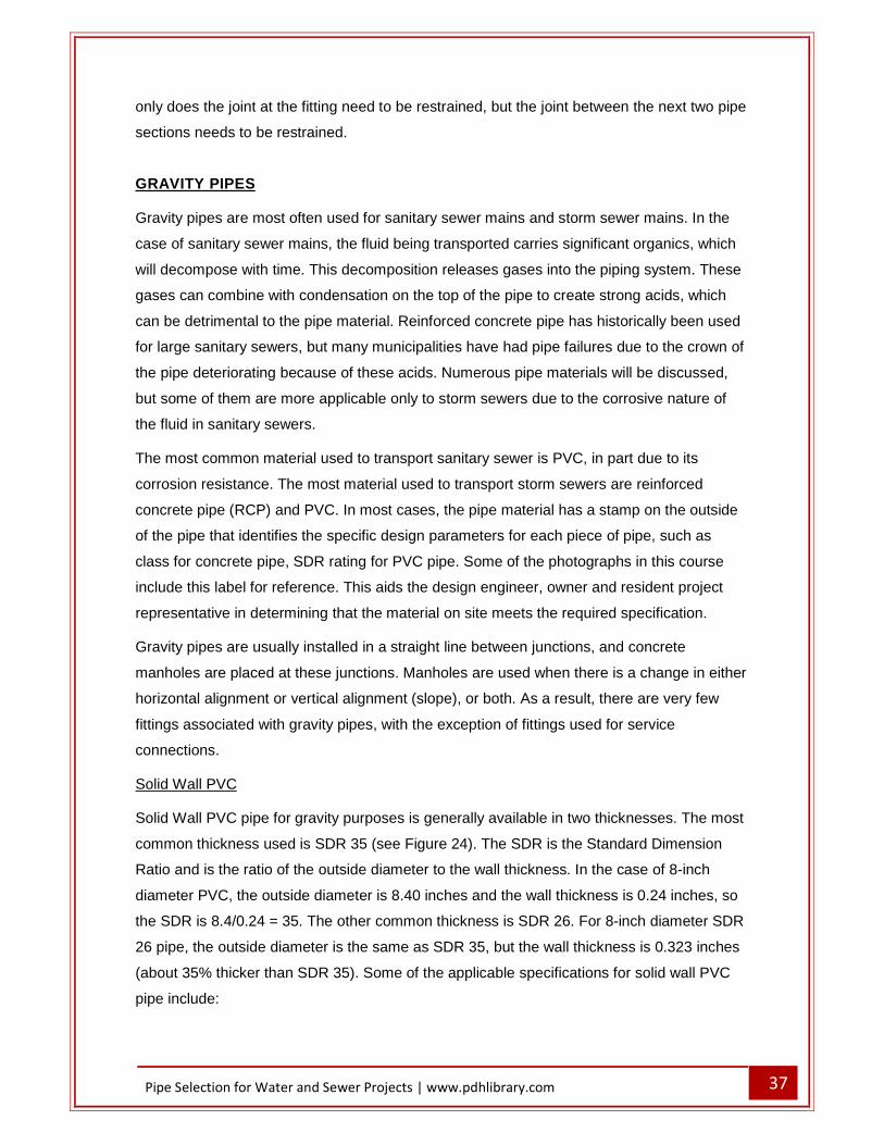
Solid Wall PVC
Solid Wall PVC pipe for gravity purposes is generally available in two thicknesses. The most
common thickness used is SDR 35 (see Figure 24). The SDR is the Standard Dimension
Ratio and is the ratio of the outside diameter to the wall thickness. In the case of 8-inch
diameter PVC, the outside diameter is 8.40 inches and the wall thickness is 0.24 inches, so
the SDR is 8.4/0.24 = 35. The other common thickness is SDR 26. For 8-inch diameter SDR
26 pipe, the outside diameter is the same as SDR 35, but the wall thickness is 0.323 inches
(about 35% thicker than SDR 35). Some of the applicable specifications for solid wall PVC
pipe include:

38 Pipe Selection for Water and Sewer Projects | www.pdhlibrary.com
� ASTM D3034 � Standard Specification for Type PSM Poly(Vinyl Chloride) (PVC) Sewer Pipe and Fittings
� ASTM F679 � Standard Specification for Poly(Vinyl Chloride) (PVC) Large-Diameter Plastic Gravity Sewer Pipe and Fittings (18�-48�)
� ASTM F794 � Standard Specification for Poly(Vinyl Chloride) (PVC) Profile Gravity Sewer Pipe and Fittings Based on Controlled Inside Diameter
� ASTM F949 � Standard Specification for Poly(Vinyl Chloride) (PVC) Corrugated Sewer Pipe With a Smooth Interior and Fittings
� ASTM F1336 � Standard Specification for Poly(Vinyl Chloride) (PVC) Gasketed Sewer Fittings
� ASTM D1784 � Standard Specification for Rigid Poly(Vinyl Chloride) (PVC) Compounds and Chlorinated Poly(Vinyl Chloride) (CPVC) Compounds
� ASTM D3212 � Standard Specification for Joints for Drain and Sewer Plastic Pipes Using Flexible Elastomeric Seals
� ASTM D2321 � Standard Practice for Underground Installation of Thermoplastic Pipe for Sewers and Other Gravity-Flow Applications
� ASTM F1417 � Standard Test Method for Installation Acceptance of Plastic Gravity Sewer Lines Using Low-Pressure Air
� ASTM D2729 � Standard Specification for Poly(Vinyl Chloride) (PVC) Sewer Pipe and Fittings
The strength of flexible gravity pipes is often described using Pipe Stiffness (PS). The pipe
stiffness is the force required to deflect the pipe 5% of its inside diameter. SDR 35 pipe has
a pipe stiffness of 46 psi and SDR 26 pipe has a pipe stiffness of 115 psi. In some
jurisdictions, the standard requirements for gravity PVC require the use of SDR 26 pipe
rather than SDR 35 pipe. This is often due to concerns about the structural strength of SDR
35 pipe. Although SDR 35 pipe is suitable for relatively deep depths, good quality
construction is necessary to provide a suitable envelope around the pipe to support this
flexible material.
Some PVC pipes for gravity service are very thin. For example, PVC pipe meeting ASTM
D2729 is available in SDR 56. This pipe is sometimes used for individual sewer systems and
service lines but is very susceptible to cracking due to the low strength. Schedule 40 and
Schedule 80 pipe meeting the requirements of ASTM D1784 are also sometimes used for
gravity applications. These pipes are identical to the pipes described for pressure purposes.
The joints for PVC gravity sewer pipe are typically gasketed joints. These joints are similar to
the joints for PVC pressure pipe but are not designed to withstand significant pressures.
They can withstand limited pressure (a few psi) and properly constructed can easily pass the
air test that is typically required for sewer pipes. The interior walls of PVC pipe are very

39 Pipe Selection for Water and Sewer Projects | www.pdhlibrary.com
smooth, so a low Manning�s n roughness values is appropriate. Laboratory testing indicates
the n value could be as low as 0.010 for clean water. However, in gravity applications, the
fluid being transported is not clean water and some settling of solids can occur. An n value of
0.011 or 0.012 is commonly used for design purposes.
Figure 24 � Solid Wall PVC Gravity Pipe
Profile Wall PVC
Another PVC pipe product that can be used in gravity flow applications is profile wall PVC
(see Figure 25). There are a number of different manufacturers of this product, and each
product looks a little different. The pipes meet ASTM F794 �Standard Specification for Poly
(Vinyl chloride) (PVC) Profile Gravity Sanitary Pipe and Fittings Based on Controlled Inside
Diameter�. This pipe has two walls. The interior wall is smooth which provides the low friction
factors that are desirable. The exterior wall is ribbed or corrugated and provides structural
strength in the same manner as in corrugated metal pipe. The two walls are fused together
during the manufacturing process. Due to the structural strength provided by the exterior
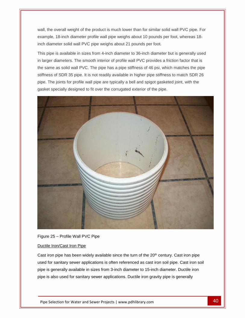
40 Pipe Selection for Water and Sewer Projects | www.pdhlibrary.com
wall, the overall weight of the product is much lower than for similar solid wall PVC pipe. For
example, 18-inch diameter profile wall pipe weighs about 10 pounds per foot, whereas 18-
inch diameter solid wall PVC pipe weighs about 21 pounds per foot.
This pipe is available in sizes from 4-inch diameter to 36-inch diameter but is generally used
in larger diameters. The smooth interior of profile wall PVC provides a friction factor that is
the same as solid wall PVC. The pipe has a pipe stiffness of 46 psi, which matches the pipe
stiffness of SDR 35 pipe. It is not readily available in higher pipe stiffness to match SDR 26
pipe. The joints for profile wall pipe are typically a bell and spigot gasketed joint, with the
gasket specially designed to fit over the corrugated exterior of the pipe.
Figure 25 � Profile Wall PVC Pipe
Ductile Iron/Cast Iron Pipe
Cast iron pipe has been widely available since the turn of the 20th century. Cast iron pipe
used for sanitary sewer applications is often referenced as cast iron soil pipe. Cast iron soil
pipe is generally available in sizes from 3-inch diameter to 15-inch diameter. Ductile iron
pipe is also used for sanitary sewer applications. Ductile iron gravity pipe is generally

41 Pipe Selection for Water and Sewer Projects | www.pdhlibrary.com
available in the same sizes as pressure pipe � 3-inch diameter to 64-inch diameter. The
ASTM Standards for this pipe are:
ASTM A74 � Standard Specification for Cast Iron Soil Pipe and Fittings.
ASTM A746 � Standard Specification for Ductile Iron Gravity Sewer Pipe.
Ductile iron pipe is typically furnished with a cement mortar lining. However, the gases that
are formed during decomposition of the organic matter in sanitary sewers can combine with
condensation in the pipe to create acids that attack the lining. Therefore, common cement-
mortar lined ductile iron pipe should not generally be used for gravity sanitary sewer
applications. It is usually suitable for force main applications, because a force main is
typically always full of fluid, so the gases are not released in the same manner as in a gravity
sewer line. Ductile iron pipe can be furnished with no lining, but the acids can also react with
the iron and deteriorate the pipe. Special linings are available to protect the interior of ductile
iron pipe from these acids. An example of a special lining for ductile iron pipe is shown in
Figure 26.
Ductile iron pipe for sanitary and storm sewer applications has the same joint options that
are available for pressure pipe � push on, mechanical and flanged. Push on joints are almost
always used for gravity applications because there are no thrust forces to resist. The cement
mortar lining creates a surface very similar to concrete pipe, so a friction value similar to that
for concrete pipe would be appropriate, such as a Manning�s n value of 0.013. Unlined cast
iron would have a potentially much higher friction factor, especially after it has been in
service for a number of years.

42 Pipe Selection for Water and Sewer Projects | www.pdhlibrary.com
Figure 26 � Epoxy coated ductile iron pipe
Reinforced Concrete Pipe
Reinforced concrete pipe (RCP) is commonly used in storm sewer applications, and less
commonly used in sanitary sewer applications. Smaller diameter RCP is concrete that is
centrifugally cast inside a form, with a cage of reinforcing steel. Different strengths of
concrete pipe are available. Stronger RCP is made using more reinforcing steel. The inside
and outside diameters of RCP are typically the same, regardless of pipe strength. Although
RCP is not designed for pressure applications, stronger pipes are necessary to resist the
loads imposed on the pipe. The most critical loads are usually the dead loads associated
with deep installations. Applicable specifications for RCP include:
ASTM C76 � �Reinforced Concrete Culvert, Storm Drain and Sewer Pipe� ASTM C443 � �Joints for Circular Concrete Sewer and Culvert Pipe, Using Rubber
Gaskets� ASTM C478 � �Precast Reinforced Concrete Manhole Sections� ASTM C361 � �Standard Specification for Reinforced Concrete Low-Head Pressure
Pipe�
RCP is available in sizes from 12-inch diameter to 120-inch diameter. RCP is available in
round pipe and in arch pipe (sometimes called �squash� pipe). Arch pipes can be valuable in

43 Pipe Selection for Water and Sewer Projects | www.pdhlibrary.com
culvert installations where there is very little available cover but are not commonly used in
storm sewer applications. The concrete interior creates a relatively smooth surface, so a
friction such as a Manning�s n value of 0.013 would be appropriate.
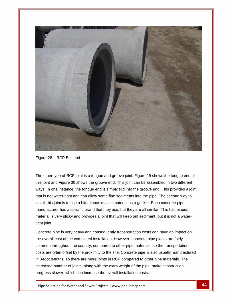
There are two different types of joints available for RCP. The first type is a bell and spigot
joint which includes a gasket. Figure 27 shows the spigot end which includes a groove for
the gasket. Figure 28 shows the bell end. The use of the o-ring gasket provides a water-tight
seal which can meet air testing requirements for gravity pipe and can even hold a limited
amount of pressure (usually a few psi).
Figure 27 � RCP spigot end with groove for o-ring gasket
44 Pipe Selection for Water and Sewer Projects | www.pdhlibrary.com
Figure 28 � RCP Bell end
The other type of RCP joint is a tongue and groove joint. Figure 29 shows the tongue end of
this joint and Figure 30 shows the groove end. This joint can be assembled in two different
ways. In one instance, the tongue end is simply slid into the groove end. This provides a joint
that is not water-tight and can allow some fine sediments into the pipe. The second way to
install this joint is to use a bituminous mastic material as a gasket. Each concrete pipe
manufacturer has a specific brand that they use, but they are all similar. This bituminous
material is very sticky and provides a joint that will keep out sediment, but it is not a water-
tight joint.
Concrete pipe is very heavy and consequently transportation costs can have an impact on
the overall cost of the completed installation. However, concrete pipe plants are fairly
common throughout the country, compared to other pipe materials, so the transportation
costs are often offset by the proximity to the site. Concrete pipe is also usually manufactured
in 8-foot lengths, so there are more joints in RCP compared to other pipe materials. The
increased number of joints, along with the extra weight of the pipe, make construction
progress slower, which can increase the overall installation costs.

45 Pipe Selection for Water and Sewer Projects | www.pdhlibrary.com
RCP is generally not used in sanitary sewer applications because the corrosive nature of the
environment inside the pipe. However, in some situations, a special type of RCP can be
used for sanitary sewer applications. It is possible to obtain RCP pipe that has a PVC liner
cast into the concrete pipe during the manufacturing process. This liner provides a reliable,
effective barrier to the hydrogen sulfide gas that comes from the decomposition of organics.
While this product is obviously more expensive that standard RCP it does provide a viable
option in larger sizes where there are limited material choices.
Figure 29 � RCP tongue end

46 Pipe Selection for Water and Sewer Projects | www.pdhlibrary.com
Figure 30 � RCP Groove End
Corrugated Metal Pipe
Corrugated metal pipe includes both steel pipe and aluminum pipe. In general, these
products are most often used for culvert applications. In some situations, they can be used
for storm sewers. They are not generally used for sanitary sewers due to corrosion
concerns. Applicable specifications for corrugated metal pipe include:
AASHTO M36 � �Corrugated Steel Pipe, Metallic-Coated, for Sewers and Drains� AASHTO M190 � �Bituminous-Coated Corrugated Metal Culvert Pipe and Pipe-
Arches� AASHTO M245 � �Corrugated Steel Pipe, Polymer Precoated, for Sewers and
Drains� AASHTO M196 � �Corrugated Aluminum Pipe for Sewers and Drains
Corrugated steel pipe is available in sizes from 12-inch diameter to 120-inch diameter.
Larger sizes are available as structural plates. Corrugated aluminum pipe is also available in
sizes from 12-inch diameter to 120-inch diameter. Corrugated steel pipes are much thinner
than solid wall steel pipes used for pressure applications. The corrugations provide

47 Pipe Selection for Water and Sewer Projects | www.pdhlibrary.com
significant structural strength to resist live and dead loads in a trench application when
properly backfilled, but they do not have the ability to withstand pressures. Figure 31 shows
a corrugated metal pipe used for a drainage culvert. The sizes represent the nominal inside
diameter. Both steel and aluminum pipe are available in arch sizes, similar to RCP. The
interior surface is typically a corrugated surface that is relatively rough. Recommended
Manning�s n values range from 0.024 to 0.034, depending on the size of the pipe and the
size of the corrugation. There are also two different types of corrugations. The pipe in Figure
31 has annular corrugations, which are concentric. Corrugated metal pipe is also available
with helical corrugations. Pipe with helical corrugations has been shown in laboratory testing
to have a lower friction factor.
Figure 31 � Corrugated Metal Pipe
One type of metal pipe is manufactured specifically for storm sewer applications. This pipe
has a spiral rib on the exterior and an interior that is essentially smooth (see Figure 32). The
spiral rib provides structural strength similar to corrugated metal pipe, but the interior is much
smoother. This pipe is generally available in sizes 18-inch to 120-inch. The manufacturer
recommends a Manning�s n of 0.012 to 0.013, based on laboratory testing with clean water.

48 Pipe Selection for Water and Sewer Projects | www.pdhlibrary.com
Figure 32 � Spiral Rib metal pipe
Corrugated High Density Polyethylene (HDPE)
Corrugated HDPE is made of high-density polyethylene, very similar to the solid wall HDPE
material used in pressure pipes. Similar to corrugated steel pipe, though, the corrugations
provide significant strength to resist live and dead loads in a gravity application. The pipe
stiffness for HDPE pipe varies by diameter. HDPE pipe with a diameter of 12-inches has a
pipe stiffness of 50 psi while 60-inch diameter pipe has a pipe stiffness of only 14 psi. This
means that larger diameter HDPE pipe is much more flexible than PVC pipe and requires
better bedding and better installation practices. Corrugated HDPE is available as single wall
pipe and double wall pipe. The single wall pipe is just an exterior corrugated wall and the
interior is also corrugated, and consequently this material has a very high friction factor.
Double wall pipe has a corrugated exterior wall and a smooth interior wall, with produces a
much lower friction factor and also provides a stronger pipe. Corrugated HDPE is lighter than
PVC � 18-inch diameter double-wall HDPE only weighs about 6 pounds per foot, compared
to 21 pounds per foot for solid wall PVC. The applicable specifications include:

49 Pipe Selection for Water and Sewer Projects | www.pdhlibrary.com
ASTM F2648 - Standard Specification for 2 to 60 inch Annular Corrugated Profile Wall Polyethylene (PE) Pipe and Fittings for Land Drainage Applications
ASTM F477 Standard Specification for Elastomeric Seals (Gaskets) for Joining Plastic Pipe
ASTM D3212 Standard Specification for Joints for Drain and Sewer Plastic Pipes Using Flexible Elastomeric Seals
Corrugated HDPE pipe is made with annular corrugations, similar to some corrugated steel
pipe. For double wall HDPE, the friction factors are similar to profile wall PVC or solid wall
PVC. The joints for HDPE pipe are typically bell and spigot (see Figure 33). This joint
includes a gasket which can make the joint watertight. However, the flexibility of this pipe, as
indicated by the low pipe stiffness, can make it somewhat difficult to construct a watertight
system. More care is required by the contractor to accomplish this task, and air testing is
strongly recommended to ensure the completed installation is watertight.
Figure 33 � HDPE Pipe, Bell End (left) and Spigot End (right)
50 Pipe Selection for Water and Sewer Projects | www.pdhlibrary.com
Vitrified Clay
Clay pipe has been in use in the United States for over 150 years and has been used in
some places for over 2500 years. Clay pipe is generally available in sizes from 4 inches to
42 inches. Based on information from the manufacturer�s association, there are over one
million miles of clay pipe installed in the United States. It was a very common material for
many years and numerous manufacturing facilities were scattered across the U.S. There are
only a few manufacturing facilities remaining in the United States, though. In areas that are
in reasonable proximity to a manufacturing facility, clay pipe is very viable option.
Clay pipe is manufactured by firing the material at 2000° F. At this temperature, vitrification
occurs as the clay mineral particles become fused into a chemically inert and stable material.
The wall thickness can vary depending on the type of clay raw materials and the processes
used in the plant to achieve strength requirements. The inside diameter of the pipe is
controlled, but the outside diameter varies depending on the raw materials used. Applicable
standards include:
� ASTM C700 � �Standard Specification for Vitrified Clay Pipe, Extra Strength,
Standard Strength and Perforated�
� ASTM C425 � �Standard Specification for Compression Joints for Vitrified Clay Pipe
and Fittings�
� ASTM C301 � �Standard Test Methods for Vitrified Clay Pipe�
� ASTM C12 � �Standard Practice for Installing Vitrified Clay Pipe Lines�
� ASTM C 828 � "The Standard Method for Low-Pressure Air Testing of Vitrified Clay Pipe�
Clay pipe is now provided with a gasketed joint (see Figure 34). For centuries, clay pipe was
provided simply with a coupling or push-together joint. Sometimes a sealant was provided in
this joint, and sometimes it wasn�t. Many old clay pipes have a very simple connection that
allows water in and out of the pipe. This promotes invasion of roots that can clog the pipe, so
many engineers don�t use clay pipe based on problems associated with older versions of the
joint. The current joint configuration provides a water-tight joint that can meet the air testing
requirements for sanitary sewers. Clay pipe is a rigid pipe, so pipe stiffness is not a design
consideration. Pipe strength to resist live loads and dead loads is a design consideration,
though.

51 Pipe Selection for Water and Sewer Projects | www.pdhlibrary.com
Figure 34 � Clay pipe gasketed joint
Profile Wall Polypropylene
Profile wall polypropylene is similar to profile wall PVC and to corrugated HDPE. It is usually
a double wall pipe, with a corrugated exterior wall and a smooth interior wall. It is available in
sizes from 12-inch diameter to 60-inch diameter. Applicable specifications include:
ASTM F2736 � �Standard Specification for 6 to 30 in. Polypropylene (PP) Corrugated
Single Wall Pipe and Double Wall Pipe� ASTM F2764 � �Standard Specification for 30 to 60 in. Polypropylene (PP) Triple
Wall Pipe and Fittings for Non-Pressure Sanitary Sewer Applications� ASTM F2881 � �Standard Specification for 12 to 60 in. Polypropylene (PP) Dual Wall
Pipe and Fittings for Non-Pressure Storm Sewer Applications�
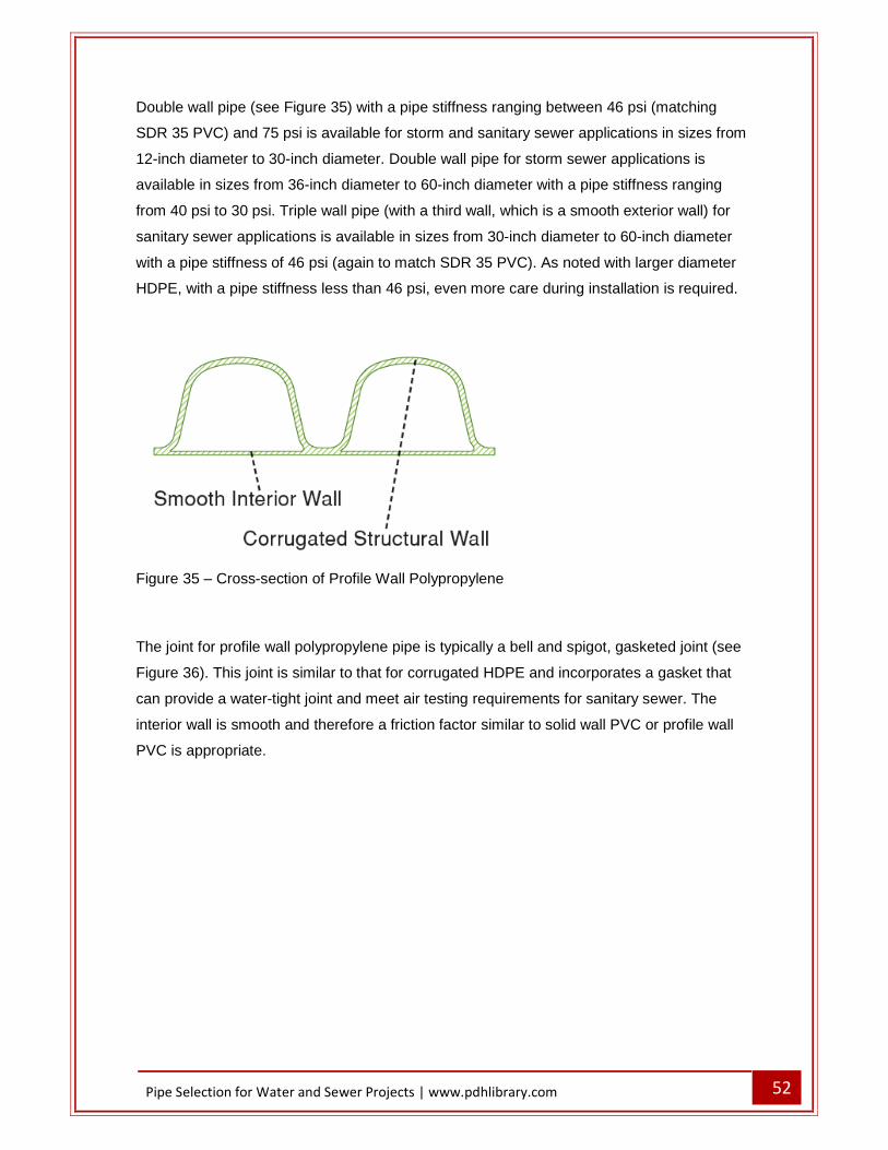
52 Pipe Selection for Water and Sewer Projects | www.pdhlibrary.com
Double wall pipe (see Figure 35) with a pipe stiffness ranging between 46 psi (matching
SDR 35 PVC) and 75 psi is available for storm and sanitary sewer applications in sizes from
12-inch diameter to 30-inch diameter. Double wall pipe for storm sewer applications is
available in sizes from 36-inch diameter to 60-inch diameter with a pipe stiffness ranging
from 40 psi to 30 psi. Triple wall pipe (with a third wall, which is a smooth exterior wall) for
sanitary sewer applications is available in sizes from 30-inch diameter to 60-inch diameter
with a pipe stiffness of 46 psi (again to match SDR 35 PVC). As noted with larger diameter
HDPE, with a pipe stiffness less than 46 psi, even more care during installation is required.
Figure 35 � Cross-section of Profile Wall Polypropylene
The joint for profile wall polypropylene pipe is typically a bell and spigot, gasketed joint (see
Figure 36). This joint is similar to that for corrugated HDPE and incorporates a gasket that
can provide a water-tight joint and meet air testing requirements for sanitary sewer. The
interior wall is smooth and therefore a friction factor similar to solid wall PVC or profile wall
PVC is appropriate.

53 Pipe Selection for Water and Sewer Projects | www.pdhlibrary.com
Figure 36 � Bell and Spigot Joint for Profile Wall Polypropylene
Steel Reinforced Corrugated HDPE
Steel reinforced corrugated HDPE is very similar to corrugated HDPE, except that steel
reinforcing ribs are included in the corrugations, providing a stronger cross-section (see
Figure 37). The available pipe sizes depend on the manufacturer but vary from 12-inch
diameter to 120-inch diameter. The applicable specifications for this pipe include:
ASTM F2562 - �Standard Specification for Steel Reinforced Thermoplastic Ribbed Pipe and
Fittings for Non-Pressure Drainage and Sewerage
ASTM D3350 - �Standard Specification for Polyethylene Plastics Pipe and Fittings Materials
This pipe combines the strength of steel with the corrosion resistance of HDPE. The joints
are typically a bell and spigot joint with a gasket, although some other joint types are
available. The gasketed joint can provide a pipe system that can meet the air testing
requirements for sanitary sewer (see Figure 38). The smooth interior allows the use of a
Manning�s n value the same as corrugated HDPE or solid wall PVC.

54 Pipe Selection for Water and Sewer Projects | www.pdhlibrary.com
Figure 37 � Steel Reinforced Corrugated HDPE Cross-Section
Figure 38 � Installed Steel Reinforced Corrugated HDPE

55 Pipe Selection for Water and Sewer Projects | www.pdhlibrary.com
Centrigually Cast Fiberglass Reinforced Polymer Mortar
Centrigually Cast Fiberglass Reinforced Polymer Mortar (CCFRPM) pipes are specialty
pipes made by a single manufacturer in the United States. The pipes are sometimes refered
to as Hobas pipes, after the manufacturer. Applicable specifications include:
i. ASTM D3262 - Standard Specification for �Fiberglass� (Glass-Fiber-Reinforced Thermosetting-Resin) Sewer Pipe
The pipes consist a a number of different layers of material. Starting from the outside of the
pipe, they consist of:
Outer layer � sand and resin
Heavily reinforced layer � chopped glass and resin
Transition � glass, resin and mortar
Core � Polymer mortar
Transition � glass, resin and mortar
Heavily reinforced layer � chopped glass and resin
Liner � high elongation resin
The two heavily reinforced layers (see Figure 39) function similarly to the flanges of an I-
beam, with the core functioning as the web of the I-beam. This design provides significant
strength. The pipe is manufacturered using a continuous casting process. The pipe is
available in sizes from 18-inch diameter to 126-inch diameter. While this pipe includes
mortar and reinforcement, it is considered a flexible pipe not a rigid pipe. Depending on size,
it is available in pipe stiffnesses of 18 psi, 36 psi, 46 psi and 72 psi.
The joints for these pipes can have a variety of different connectors. Bell and spigot joints
area available along with several different couplings. All of the joints are water-tight and can
meet the air-testing requirements of sanitary sewers. These large diameter pipes are ideally
suited for nearly all corrosive piping applications. Pipes can be individually designed for non-
pressure and pressure service by varying the quantity, placement, and orientation of the
glass-fiber reinforcements. While this is a proprietary product and a specialty product, it is
very resistant to the corrosion of sanitary sewers and can be a viable product in that
application. The interior lining is very smooth so the friction factor is at least as low as any of
the other products described.

56 Pipe Selection for Water and Sewer Projects | www.pdhlibrary.com
Figure 39 � CCFRPM cross-section
PIPE INSTALLATIONS Bedding and Backfill Proper installation of any pipe material requires appropriate bedding and backfill. Bedding commonly refers to the material under and around the pipe and backfill is the material above the pipe, to the ground surface. Most of the pipes used for pressure and sewer applications are flexible pipes. These include ductile iron (although it is obviously not as flexible as other materials), PVC, HDPE, polypropylene and CCFRPM. The only rigid pipes used for pressure and sewer applications are reinforced concrete and clay. Asbestos cement pipe is also a rigid pipe. When rigid pipe is installed, most of the structural components of the installation arrive on the truck in the form of the pipe. When flexible pipe is installed, the pipe essentially functions as a form for the structure, similar to the forms used in concrete construction. The structure for flexible pipe is created by the contractor by installing bedding and backfill under, around and over the pipe. It is therefore very important that the bedding and backfill be appropriate materials and be installed correctly. A flexible pipe deforms slightly (becoming egg-shaped) and this deformation transfers the vertical load (live load and dead load) from the top of the pipe to the soils on the sides of the pipe. If the soils around the pipe do not provide solid support, the pipe will deform excessively, causing premature failure of the pipe. There are several zones of material that are important in the installation of pipe. Starting at the bottom of the trench, the first zone is the bedding material under the pipe. This material is often a granular material, sometimes washed gravel because it is easy to work with and provides good support. This material is required to bring the trench bottom up to the desired grade, which is critical in installation of gravity pipe. This material also provides uniform longitudinal support under the pipe. For pipes that have bell and spigot joints (almost all of the pipe materials discussed have this type of joint), a small amount of bedding will be removed from under the bell, to allow the pipe to be installed on grade. Under normal conditions, a depth of bedding of 4 to 6 inches under the pipe will be suitable. If the native soils at the level of the pipe bedding are fine-grained soils, there is the potential for these

57 Pipe Selection for Water and Sewer Projects | www.pdhlibrary.com
soils to migrate into the bedding material over time. If this happens, eventually the surface of the trench will settle which is usually an undesirable condition. To prevent this, the use of well-graded bedding material which reduces the void spaces available for migration or a fabric to separate the bedding material from the native soils. The next zone of material is the pipe zone, which is material adjacent to the pipe. This zone includes the haunch of the pipe which is the area below the centerline of the pipe (sometimes called the spring line of the pipe). It is important to get material against the lower part of the pipe, but this takes some care during construction to insure that an adequate amount of material is placed under the haunches of the pipe, but not so much material that the grade of the pipe is changed. A flowable material such as washed gravel or sand is often used to make this easier. A high degree of compaction is not usually necessary for this layer of material, but this material does need to be compacted uniformly. The material from the centerline of the pipe to the top of the pipe needs to be carefully placed to continue to create the structure for the installation and a high-quality material is needed. Sometimes the native soils are suitable for use above the spring line of the pipe. Installation should be in lifts, installed uniformly on both sides of the pipe in order to maintain the circular shape of the pipe. If too much material is placed on one side before any material is placed on the other side, the pipe will lose its shape and its ability to resist additional loads. The first layer above the top of the pipe is also part of the pipe embedment zone. This material should be select material, with no rocks greater than 1.5 inches in size, no lumps of dirt, frozen material or organic material. This material provides protection for the pipe from objects that may fall into the trench and needs to be well-compacted to provide the necessary structural support. At shallow depths of cover (less than 3 feet) flexible conduits may deflect and rebound under traffic loading if the trench is not well compacted. This can result in damage to the roadway surface because pavements are not designed for this amount of repeated deflection. In this situation, all of the backfill material should be granular material. Depth of Cover Pipe manufacturers generally provide minimum and maximum depths of cover for their products. However, the manufacturers are not all consistent on the parameters used to make recommendations for allowable depths of cover. The loads on a pipe include live loads and dead loads. The live loads depend on the use of the surface and the depth of the pipe. A summary of these loads is shown in Table 3 for highway, railroad and airport conditions. Note that the surface use impacts the live loads significantly and the live loads decrease quickly with additional depth.

58 Pipe Selection for Water and Sewer Projects | www.pdhlibrary.com
Table 3 Live Loads
Based on Surface Use and Cover
Height of Cover (ft) Live Load Transferred to Pipe, psi
Highway Railway Airport
1 12.5 * *
2 5.56 26.39 13.14
3 4.17 23.61 12.28
4 2.78 18.49 11.27
5 1.74 16.67 10.09
6 1.39 15.63 8.79
7 1.22 12.15 7.85
8 0.69 11.11 6.93
10 * 7.64 6.09
12 * 5.56 4.76
The recommended minimum cover for different pipe materials is shown in Table 4. Note that the cover for HDPE, which is a very flexible material, is less than that for ductile iron or steel. Keep in mind that these are manufacturers recommendations and while protection of the pipe is important, protection of the surface, especially if it is pavement, is also important.
Table 4 Minimum Cover for Pipes
Based on Manufacturers Recommendations
Pipe Material Minimum cover, ft
Ductile Iron 2.5
C900 PVC 3 *
Steel 3
SDR 35 PVC 3 *
HDPE 1
Concrete 1 � 2 **

59 Pipe Selection for Water and Sewer Projects | www.pdhlibrary.com
* Can be reduced to one foot with a backfill envelope of granular materials ** Depending on diameter The recommended maximum cover for different pipe materials is shown in Table 5. Again, these are manufacturers recommendations. For maximum cover, the class of the pipe in ductile iron, PVC, steel, HDPE and concrete makes a difference. In many cases, the type of soil material in the bedding and backfill also influences the maximum cover. The values shown in Table 5 should be verified for every installation.
Table 5
Maximum Cover for Pipes Based on Manufacturers Recommendations
Pipe Material Maximum cover, ft
Ductile Iron 20 - 50
C900 PVC 20
Steel 15 - 50
SDR 35 PVC 20
Corrugated HDPE 20
Concrete 15 - 50
Clay 20
Pressure Testing for Pressure Pipes Pressure testing of pressure pipes immediately after installation is highly recommended and usually required by the project specifications. The test pressure varies depending on the pressures that the pipeline will encounter and by the safety factors included in the design. As a minimum the test pressure should equal the maximum working pressure of the pipeline, including any surge pressures that could occur. Sometimes the test pressure is defined as 150% of the working pressure. It is important to verify the location of the maximum test pressure measurement, especially on pipelines that have significant variation in elevation. The maximum test pressure is usually stated at the point of maximum pressure, which would be the lowest elevation. If the pressure is measured at a higher elevation, the test pressure at the low spot will be greater than the desired test pressure, which could cause a pipe failure. To complete the pressure test, the installation of the pipeline must be completed. This needs to include at least enough backfill to keep the pipe in place during testing and needs to include all thrust restraint. If thrust blocks are used, the concrete must be adequately cured to achieve the required strength of the concrete. The pipe is slowly filled from one end and air allowed to discharge from the other end. Once the pipe is completely full, then the test pump is allowed to increase the pressure in the pipeline to the test pressure.

60 Pipe Selection for Water and Sewer Projects | www.pdhlibrary.com
As part of the pressure test, a leakage test is also conducted. A two-hour test is usually sufficient. In the leakage test, the pressure in the pipe is raised to the test pressure, then allowed to set for two hours. After two hours, the test pump is used to raise the pressure in the pipeline back to the original test pressure and the volume of water needed to accomplish this is measured. The allowable leaking is usually calculated by the formula: L = N * D * (P0.5) / 7400 Where: L = allowable leakage, in gallons per hour N = number of joints in the pipe being tested D = nominal diameter of the pipeline P = test pressure in psi. If the amount of water necessary to re-pressurized the pipe is less than the allowable leakage, then the pipe passes the pressure test. If the amount of water is greater than the allowable leakage, the pipe doesn�t pass the pressure test. There are three likely reasons
that a pipe might not pass the pressure test. They are: 1. There is a leak in the system that needs to be fixed. 2. All of the air was not removed from the system before the pressure test. If
this is the case, another pressure test can be conducted and it may pass. 3. The pipeline was not adequately isolated from the existing system. It is
very difficult to isolate a pipeline that is connected to an existing system unless there is a new gate valve installed at each connection point. Otherwise, some of the existing system is being tested, including an old valve, and the pressure test is not an adequate test of the new installation. To avoid this problem, it is important during design of the new pipeline to consider how the system is going to be tested.
A pipeline that was properly installed should have very little difficulty passing both the pressure and leakage tests. A pipeline that doesn�t pass these tests almost always has a
problem that should be fixed before the line is put in service. Leak Testing for Gravity Pipes Leakage testing of gravity pipes after installation is highly recommended. It is usually required for sanitary sewers and sometimes required for storm sewers. The leakage test ensures that the sewer line has been properly installed. It is also common for most projects to require a video camera be used through the pipeline to look for obvious problems (such as rolled gaskets or joints that have pulled apart). Some jurisdictions prefer to only do the video examination, thinking that it is possible to see all of the problems and that the leakage test is an unnecessary expense. However, it is very possible for a small crack in a pipe to be essentially undetectable by camera, but the crack would allow enough air to leave the pipe that a leakage test would fail. A crack in a newly constructed pipe certainly should not be allowed, so it is recommended that testing for gravity lines include a leakage test. There are two types of leakage tests performed on gravity pipes. The preferred method is usually an air test. A leakage test using water can be performed, but this is a more cumbersome test and requires significant quantities of water. The air test is performed by plugging both ends of a section of pipeline at the manhole and then pressurizing the air within the pipeline. The air pressure is usually raised to 4.0 psi, lowered to 3.5 psi through a valve, then the time is measured for the pressure to drop to 2.5 psi. The minimum allowable time for this pressure drop is calculated based on 3.5 cubic feet per minute or 0.003 cubic feet per minute per square foot of internal surface area of the pipe being tested. If the pressure drop takes longer than the allowable time, the test is successful.

61 Pipe Selection for Water and Sewer Projects | www.pdhlibrary.com
Pipe Selection for Water and Sewer Projects Updated: 4/6/2020
1. Which of the following would be expected to have the thinnest wall?
a. Old cast iron pressure pipe b. Old ductile iron pressure pipe c. New ductile iron pressure pipe d. They should all have the same wall thickness
2. How does the outside diameter of Special Thickness Class (STC) ductile iron pipe compare
to the outside diameter of Pressure Class (PC) ductile iron pipe?
a. STC pipe has a larger OD b. PC pipe has a larger OD c. The OD of both classes are the same d. It varies depending on pipe size
3. What is the pressure rating for Special Thickness Class 52 ductile iron pipe?
a. 150 psi b. 250 psi c. 350 psi d. It depends on the pipe diameter
4. What is the most common internal corrosion protection used for ductile iron pipe for
water applications?
a. Cement mortar lining b. Polyethylene encasement c. Epoxy coating d. None of the above
5. Which of the following pipes has the thickest wall?
a. 12� DR 14 b. 12� DR 18 c. 12� DR 25 d. 12� SDR 26

62 Pipe Selection for Water and Sewer Projects | www.pdhlibrary.com
6. What is the surge allowance included in AWWA C900 for PVC Pipe?
a. 0 psi b. 35 psi c. 100 psi d. None of the above
7. Which of the following PVC pipes has an outside diameter that matches ductile iron pipe?
a. ASTM D2241 b. ASTM D1784 c. AWWA C900 d. None of the above
8. What is the most common joint used for solid wall HDPE for pressure applications?
a. Push On b. Flanged c. Heat fused d. Mechanical joint
9. The outside diameter of HDPE pipe conforms to which of the following standards:
a. Ductile Iron Pipe Size b. Iron Pipe Size c. It can be either of the above d. None of the above
10. The inside diameter of 12-inch HDPE meeting IPS standards is about:
a. 8 inches b. 10 inches c. 12 inches d. 14 inches
11. Which of the following is the most common interior coating for smooth steel pipe?
a. Epoxy b. Polyurethane c. Cement mortar d. None of the above

63 Pipe Selection for Water and Sewer Projects | www.pdhlibrary.com
12. Which of the following is the most common exterior coating for smooth steel pipe?
a. Tape b. Epoxy c. Polyurethane d. None of the above
13. With a tape coating on the exterior of the steel pipe, what is the primary function of the
outside layer of tape?
a. Corrosion protection b. Mechanical protection c. Both of the above d. None of the above
14. Which of the following is the most common ductile iron joint used in underground
applications?
a. Mechanical joint b. Push-on joint c. Flanged joint d. Solvent joint
15. Which of the following joint types for ductile iron pipe do not include bolts?
a. Push on joints b. Mechanical joints c. Flanged joints d. Both push on and mechanical joints
16. PVC Pipe meeting which of the following specifications is likely to have a solvent-weld
joint?
a. AWWA C900 b. ASTM D1784 c. ASTM D2241 d. None of the above

64 Pipe Selection for Water and Sewer Projects | www.pdhlibrary.com
17. Which of the following is not a standard bend angle for ductile iron fittings?
a. 90 degrees b. 45 degrees c. 30 degrees d. 11.25 degrees
18. For a given size of pipe and working pressure, which of the following bends would have
the largest thrust force?
a. 90-degree bend b. 45-degree bend c. 22.5-degree bend d. They are all the same
19. The thrust force that needs to be resisted at a gate valve is the same as the thrust force
from which of the following fittings?
a. 90 degree bend b. 45-degree bend c. Branch of a tee d. Dead End
20. The size of a thrust block is dependent on which of the following parameters:
a. Soil bearing pressure b. Working pressure of the pipeline c. Size of the pipeline d. All of the above
21. Which of the following parameters is necessary to calculate the length of pipe that
needs to be restrained at a bend?
a. Angle of the bend b. Test pressure c. Depth of bury d. All of the above

65 Pipe Selection for Water and Sewer Projects | www.pdhlibrary.com
22. Which of the following is the most common PVC pipe used for gravity applications?
a. SDR 26 b. SDR 35 c. DR 14 d. DR 18
23. Pipe stiffness is a measure of the flexibility of a pipe. It is the force required to deflect a
pipe how much?
a. 1% of the inside diameter b. 5% of the inside diameter c. 7.5% of the inside diameter d. 10% of the inside diameter
24. Which of the following 18-inch diameter gravity pipes weighs the least?
a. Solid wall PVC b. Profile wall PVC c. Corrugated HDPE d. Reinforced Concrete
25. Which of the following is a water-tight joint for RCP?
a. Bell and spigot with o-ring b. Tongue and groove c. Tongue and groove with bituminous mastic d. None of the above
26. Corrugated metal pipe is constructed with which of the following types of corrugations?
a. Annular b. Helical c. Both of the above d. None of the above
27. Corrugated HDPE pipe is constructed with which of the following types of corrugations?
a. Annular b. Helical c. Both of the above d. None of the above
66 Pipe Selection for Water and Sewer Projects | www.pdhlibrary.com
28. With vitrified clay pipe, the type of clay used impacts which of the following dimensions?
a. The inside diameter b. The outside diameter c. Both of the above d. None of the above
29. Corrugated Polypropylene drainage pipe in many sizes is manufactured to have the
same pipe stiffness as SDR 35 PVC. What is the pipe stiffness value for SDR 35 PVC?
a. 30 psi b. 46 psi c. 115 psi d. None of the above
30. Which of the following materials is available with a steel reinforced center for gravity applications?
a. Solid wall PVC b. Profile wall PVC c. Corrugated HDPE d. Corrugated polyethylene
31. What is the recommended depth of bedding material under a pipe in normal conditions?
a. None b. 4 to 6 inches c. 8 to 12 inches d. 24 inches
32. With a height of cover of 5 feet, which of the following live loads is the largest? a. Highway b. Railway c. Airport d. They are all equal
33. The test pressure for a pressure pipe needs to include which of the following? a. Normal working pressure b. Surge pressure c. Both of the above d. None of the above