standard details engineering - s3.amazonaws.comdetails/standard+details... · detail date detail id...
TRANSCRIPT
Standard Details & SpecificationsSewers
CITY OF PHILADELPHIAWATER DEPARTMENT
DESIGN BRANCH
STANDARD DETAILSand
SPECIFICATIONSfor
SEWERS
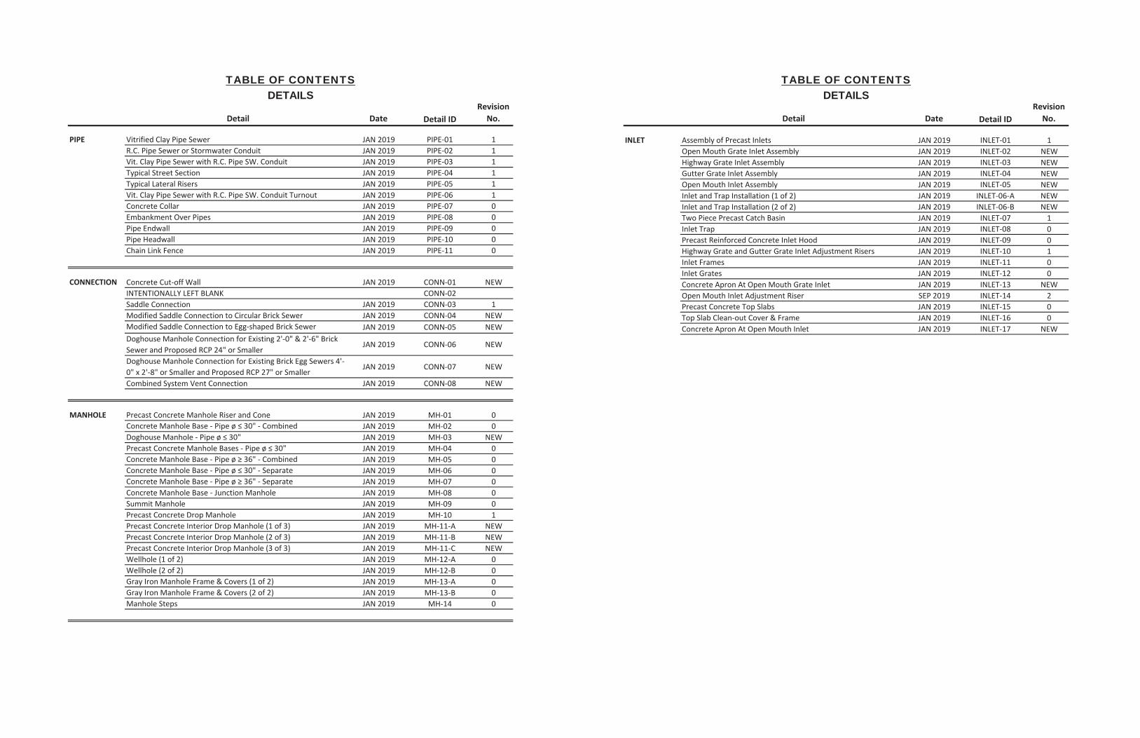
Detail Date Detail IDRevision
No.
PIPE Vitrified Clay Pipe Sewer JAN 2019 PIPE-01 1R.C. Pipe Sewer or Stormwater Conduit JAN 2019 PIPE-02 1Vit. Clay Pipe Sewer with R.C. Pipe SW. Conduit JAN 2019 PIPE-03 1Typical Street Section JAN 2019 PIPE-04 1Typical Lateral Risers JAN 2019 PIPE-05 1Vit. Clay Pipe Sewer with R.C. Pipe SW. Conduit Turnout JAN 2019 PIPE-06 1Concrete Collar JAN 2019 PIPE-07 0Embankment Over Pipes JAN 2019 PIPE-08 0Pipe Endwall JAN 2019 PIPE-09 0Pipe Headwall JAN 2019 PIPE-10 0Chain Link Fence JAN 2019 PIPE-11 0
CONNECTION Concrete Cut-off Wall JAN 2019 CONN-01 NEWINTENTIONALLY LEFT BLANK CONN-02Saddle Connection JAN 2019 CONN-03 1Modified Saddle Connection to Circular Brick Sewer JAN 2019 CONN-04 NEWModified Saddle Connection to Egg-shaped Brick Sewer JAN 2019 CONN-05 NEWDoghouse Manhole Connection for Existing 2'-0" & 2'-6" Brick Sewer and Proposed RCP 24" or Smaller
JAN 2019 CONN-06 NEW
Doghouse Manhole Connection for Existing Brick Egg Sewers 4'-0" x 2'-8" or Smaller and Proposed RCP 27" or Smaller
JAN 2019 CONN-07 NEW
Combined System Vent Connection JAN 2019 CONN-08 NEW
MANHOLE Precast Concrete Manhole Riser and Cone JAN 2019 MH-01 0Concrete Manhole Base - Pipe ø JAN 2019 MH-02 0
JAN 2019 MH-03 NEWJAN 2019 MH-04 0
Concrete Manhole Base - Pipe ø 36" - Combined JAN 2019 MH-05 0Concrete Manhole Base - Pipe ø JAN 2019 MH-06 0Concrete Manhole Base - Pipe ø 36" - Separate JAN 2019 MH-07 0Concrete Manhole Base - Junction Manhole JAN 2019 MH-08 0Summit Manhole JAN 2019 MH-09 0Precast Concrete Drop Manhole JAN 2019 MH-10 1Precast Concrete Interior Drop Manhole (1 of 3) JAN 2019 MH-11-A NEWPrecast Concrete Interior Drop Manhole (2 of 3) JAN 2019 MH-11-B NEWPrecast Concrete Interior Drop Manhole (3 of 3) JAN 2019 MH-11-C NEWWellhole (1 of 2) JAN 2019 MH-12-A 0Wellhole (2 of 2) JAN 2019 MH-12-B 0Gray Iron Manhole Frame & Covers (1 of 2) JAN 2019 MH-13-A 0Gray Iron Manhole Frame & Covers (2 of 2) JAN 2019 MH-13-B 0Manhole Steps JAN 2019 MH-14 0
TABLE OF CONTENTSDETAILS
TABLE OF CONTENTSDETAILS
Detail Date Detail IDRevision
No.
INLET Assembly of Precast Inlets JAN 2019 INLET-01 1Open Mouth Grate Inlet Assembly JAN 2019 INLET-02 NEWHighway Grate Inlet Assembly JAN 2019 INLET-03 NEWGutter Grate Inlet Assembly JAN 2019 INLET-04 NEWOpen Mouth Inlet Assembly JAN 2019 INLET-05 NEWInlet and Trap Installation (1 of 2) JAN 2019 INLET-06-A NEWInlet and Trap Installation (2 of 2) JAN 2019 INLET-06-B NEWTwo Piece Precast Catch Basin JAN 2019 INLET-07 1Inlet Trap JAN 2019 INLET-08 0Precast Reinforced Concrete Inlet Hood JAN 2019 INLET-09 0Highway Grate and Gutter Grate Inlet Adjustment Risers JAN 2019 INLET-10 1Inlet Frames JAN 2019 INLET-11 0Inlet Grates JAN 2019 INLET-12 0Concrete Apron At Open Mouth Grate Inlet JAN 2019 INLET-13 NEWOpen Mouth Inlet Adjustment Riser SEP 2019 INLET-14 2Precast Concrete Top Slabs JAN 2019 INLET-15 0Top Slab Clean-out Cover & Frame JAN 2019 INLET-16 0Concrete Apron At Open Mouth Inlet JAN 2019 INLET-17 NEW
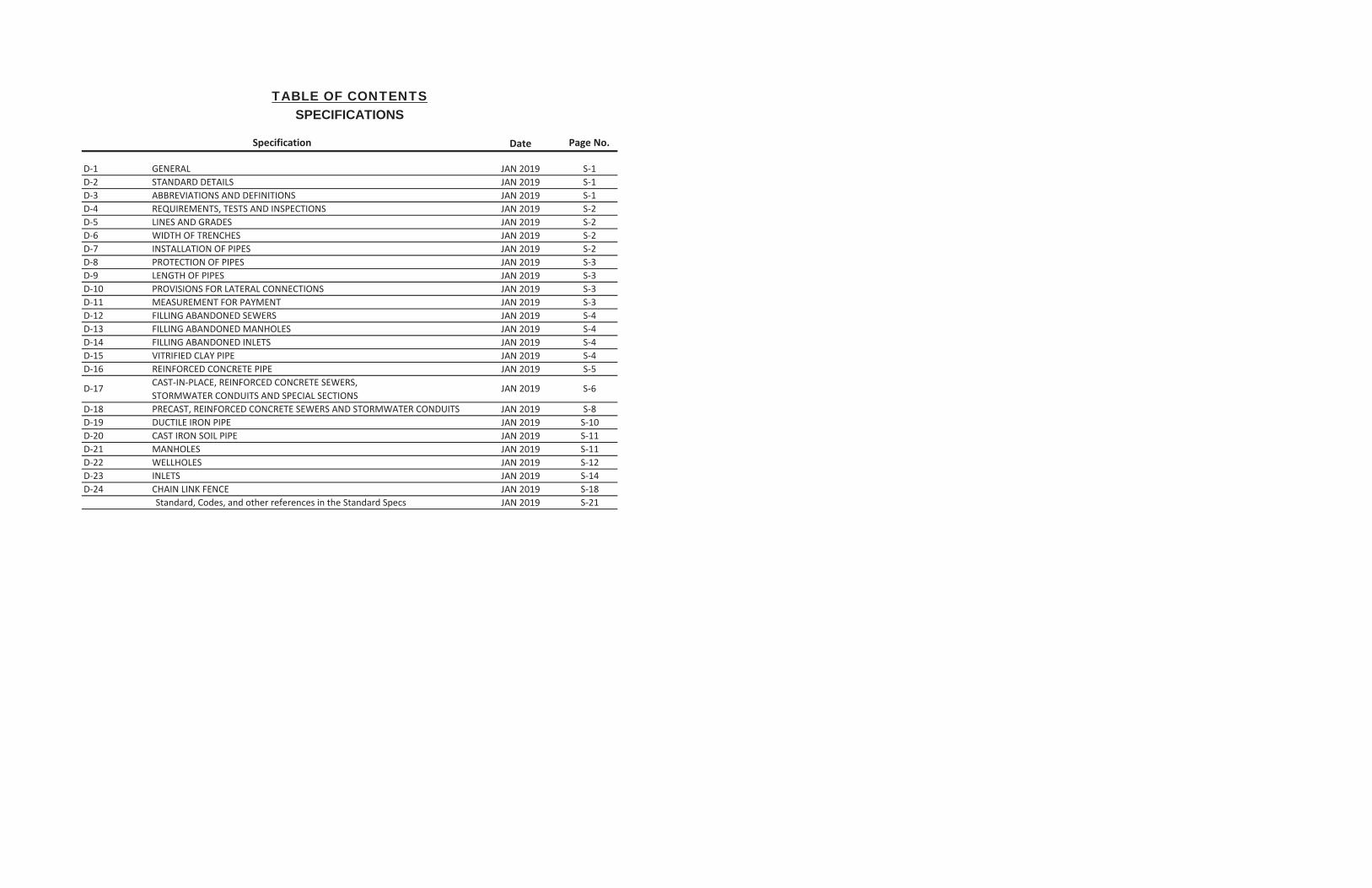
Specification Date Page No.
D-1 GENERAL JAN 2019 S-1D-2 STANDARD DETAILS JAN 2019 S-1D-3 ABBREVIATIONS AND DEFINITIONS JAN 2019 S-1D-4 REQUIREMENTS, TESTS AND INSPECTIONS JAN 2019 S-2D-5 LINES AND GRADES JAN 2019 S-2D-6 WIDTH OF TRENCHES JAN 2019 S-2D-7 INSTALLATION OF PIPES JAN 2019 S-2D-8 PROTECTION OF PIPES JAN 2019 S-3D-9 LENGTH OF PIPES JAN 2019 S-3D-10 PROVISIONS FOR LATERAL CONNECTIONS JAN 2019 S-3D-11 MEASUREMENT FOR PAYMENT JAN 2019 S-3D-12 FILLING ABANDONED SEWERS JAN 2019 S-4D-13 FILLING ABANDONED MANHOLES JAN 2019 S-4D-14 FILLING ABANDONED INLETS JAN 2019 S-4D-15 VITRIFIED CLAY PIPE JAN 2019 S-4D-16 REINFORCED CONCRETE PIPE JAN 2019 S-5
D-18 PRECAST, REINFORCED CONCRETE SEWERS AND STORMWATER CONDUITS JAN 2019 S-8D-19 DUCTILE IRON PIPE JAN 2019 S-10D-20 CAST IRON SOIL PIPE JAN 2019 S-11D-21 MANHOLES JAN 2019 S-11D-22 WELLHOLES JAN 2019 S-12D-23 INLETS JAN 2019 S-14D-24 CHAIN LINK FENCE JAN 2019 S-18
JAN 2019 S-21
D-17 JAN 2019
Standard, Codes, and other references in the Standard Specs
TABLE OF CONTENTSSPECIFICATIONS
CAST-IN-PLACE, REINFORCED CONCRETE SEWERS, STORMWATER CONDUITS AND SPECIAL SECTIONS
S-6

VITRIFIED CLAY PIPE SEWER
Detail – Vitrified Clay Pipe Sewer PIPE-01
Applicable Specifications D-1: General, D-2: Standard Details, D-3: Abbreviations and Definitions, D-4: Requirements, Tests and Inspections D-5: Lines and Grades D-6: Width of Trenches D-7: Installation of Pipes D-8: Protection of Pipes D-9: Length of Pipes D-10: Provisions for Lateral Connections D-15: Vitrified Clay Pipe
Approved Suppliers QC-9: Vitrified Clay Pipe & Fittings
Miscellaneous Comments The .dwg file located on the website at phillywaterdesign.org has drawings of all sizes of Vit. Clay Pipe Sewer in the model space. The thickness (t) of Vitrified Clay Pipe varies with each manufacturer. See the manufacturer’s website for the actual thickness.
Revisions Rev 1 – CY/LF of Concrete corrected, (t) column removed from table.
R.C. PIPE SEWER ORSTORMWATER CONDUIT
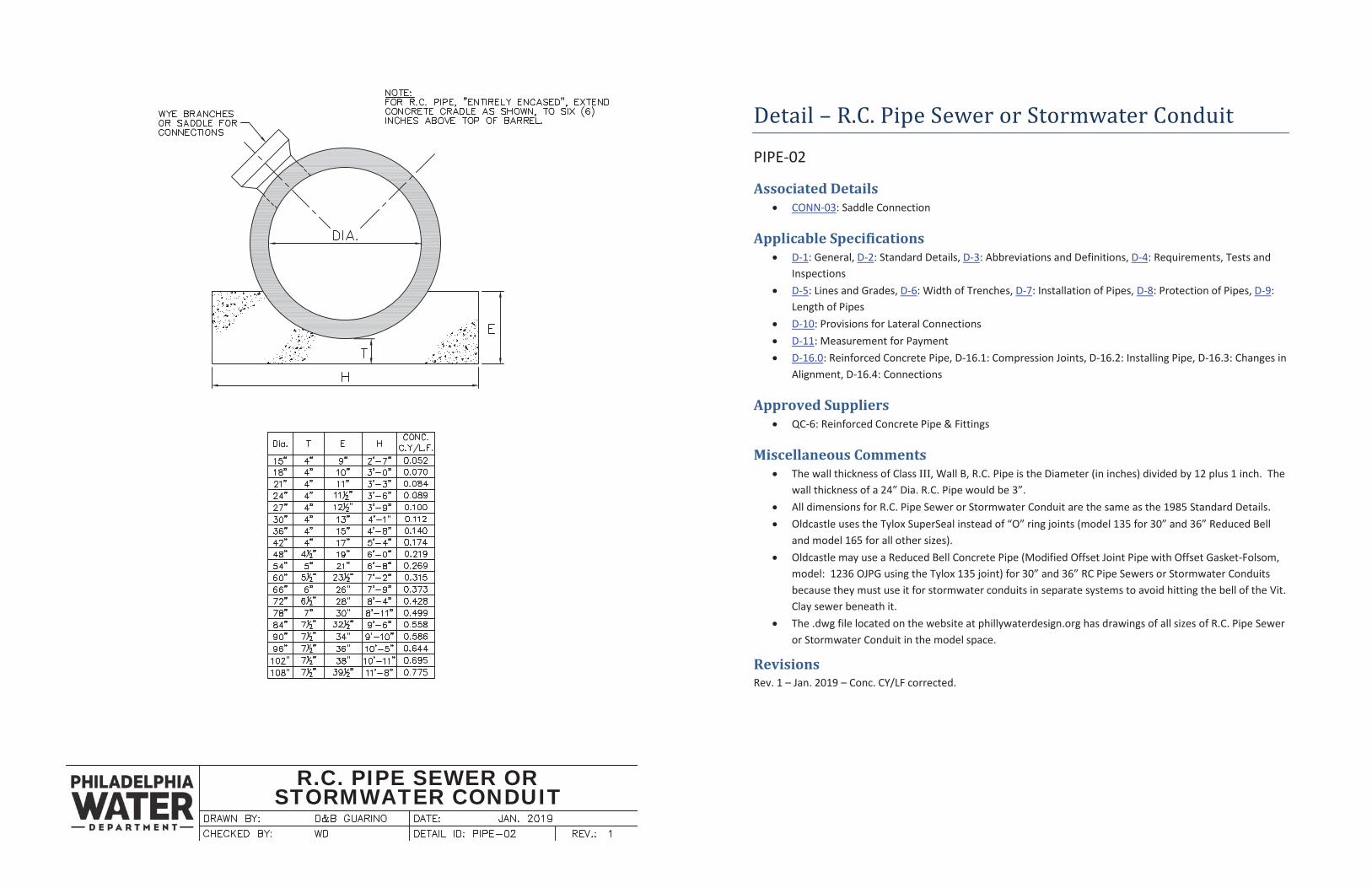
Detail – R.C. Pipe Sewer or Stormwater Conduit
PIPE-02
Associated Details CONN-03: Saddle Connection
Applicable Specifications D-1: General, D-2: Standard Details, D-3: Abbreviations and Definitions, D-4: Requirements, Tests and Inspections D-5: Lines and Grades, D-6: Width of Trenches, D-7: Installation of Pipes, D-8: Protection of Pipes, D-9: Length of Pipes D-10: Provisions for Lateral Connections D-11: Measurement for Payment D-16.0: Reinforced Concrete Pipe, D-16.1: Compression Joints, D-16.2: Installing Pipe, D-16.3: Changes in Alignment, D-16.4: Connections
Approved Suppliers QC-6: Reinforced Concrete Pipe & Fittings
Miscellaneous Comments The wall thickness of Class III, Wall B, R.C. Pipe is the Diameter (in inches) divided by 12 plus 1 inch. The wall thickness of a 24” Dia. R.C. Pipe would be 3”. All dimensions for R.C. Pipe Sewer or Stormwater Conduit are the same as the 1985 Standard Details. Oldcastle uses the Tylox SuperSeal instead of “O” ring joints (model 135 for 30” and 36” Reduced Bell and model 165 for all other sizes). Oldcastle may use a Reduced Bell Concrete Pipe (Modified Offset Joint Pipe with Offset Gasket-Folsom, model: 1236 OJPG using the Tylox 135 joint) for 30” and 36” RC Pipe Sewers or Stormwater Conduits because they must use it for stormwater conduits in separate systems to avoid hitting the bell of the Vit. Clay sewer beneath it. The .dwg file located on the website at phillywaterdesign.org has drawings of all sizes of R.C. Pipe Sewer or Stormwater Conduit in the model space.
Revisions Rev. 1 – Jan. 2019 – Conc. CY/LF corrected.
VIT. CLAY PIPE SEWER WITHRCP SW. CONDUIT
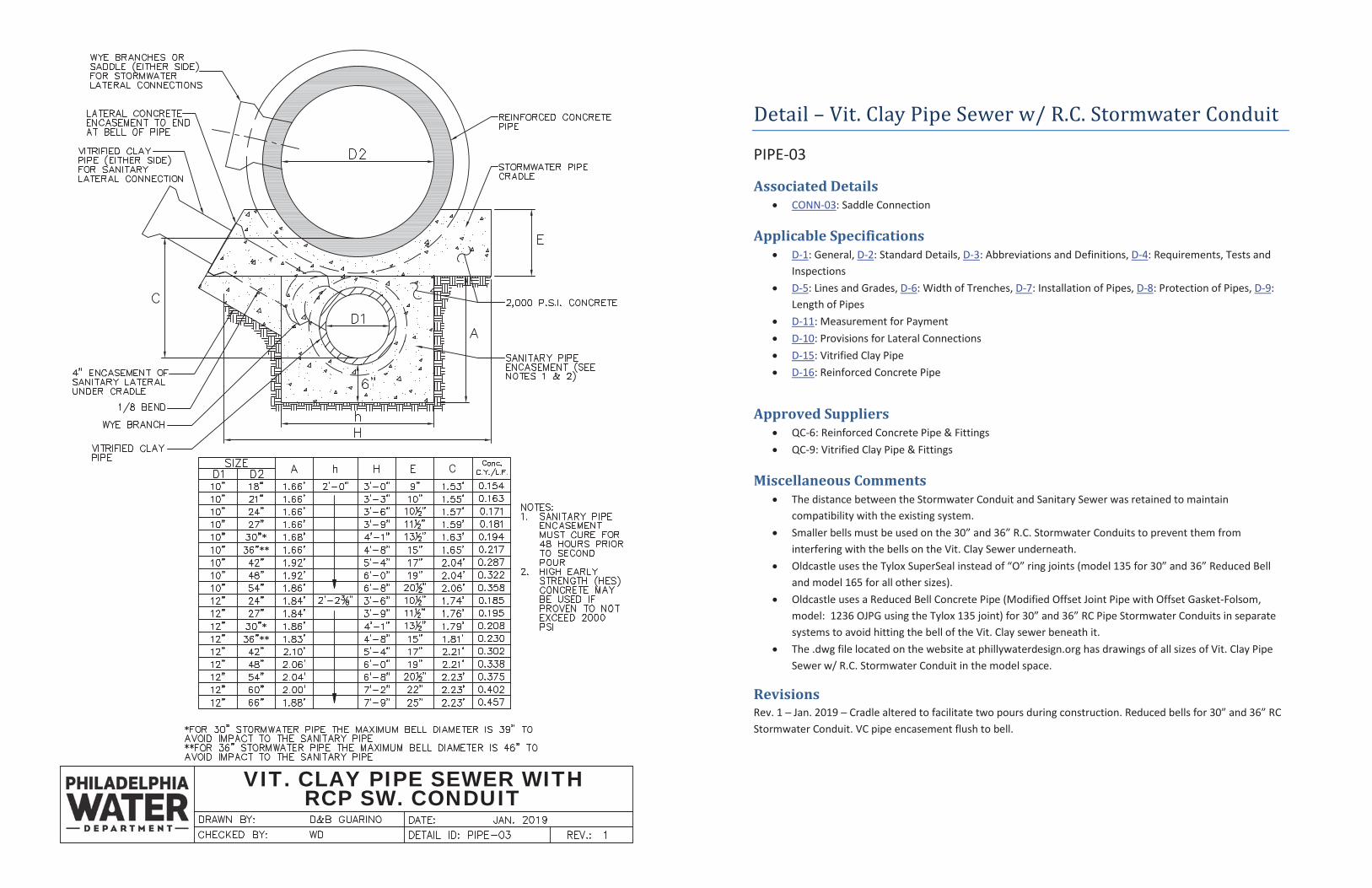
Detail – Vit. Clay Pipe Sewer w/ R.C. Stormwater Conduit
PIPE-03
Associated Details CONN-03: Saddle Connection
Applicable Specifications D-1: General, D-2: Standard Details, D-3: Abbreviations and Definitions, D-4: Requirements, Tests and Inspections D-5: Lines and Grades, D-6: Width of Trenches, D-7: Installation of Pipes, D-8: Protection of Pipes, D-9: Length of Pipes D-11: Measurement for Payment D-10: Provisions for Lateral Connections D-15: Vitrified Clay Pipe D-16: Reinforced Concrete Pipe
Approved Suppliers QC-6: Reinforced Concrete Pipe & Fittings QC-9: Vitrified Clay Pipe & Fittings
Miscellaneous Comments The distance between the Stormwater Conduit and Sanitary Sewer was retained to maintain compatibility with the existing system. Smaller bells must be used on the 30” and 36” R.C. Stormwater Conduits to prevent them from interfering with the bells on the Vit. Clay Sewer underneath. Oldcastle uses the Tylox SuperSeal instead of “O” ring joints (model 135 for 30” and 36” Reduced Bell and model 165 for all other sizes). Oldcastle uses a Reduced Bell Concrete Pipe (Modified Offset Joint Pipe with Offset Gasket-Folsom, model: 1236 OJPG using the Tylox 135 joint) for 30” and 36” RC Pipe Stormwater Conduits in separate systems to avoid hitting the bell of the Vit. Clay sewer beneath it. The .dwg file located on the website at phillywaterdesign.org has drawings of all sizes of Vit. Clay Pipe Sewer w/ R.C. Stormwater Conduit in the model space.
Revisions Jan. 2019 facilitate two pours during construction. Reduced bells for 30” and 36” RC
Stormwater Conduit. VC pipe encasement flush to bell.
TYPICAL STREET SECTION
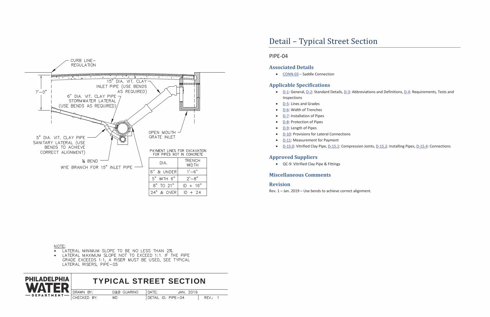
Detail – Typical Street Section
PIPE-04
Associated Details CONN-03 Saddle Connection
Applicable Specifications D-1: General, D-2: Standard Details, D-3: Abbreviations and Definitions, D-4: Requirements, Tests and Inspections D-5: Lines and Grades D-6: Width of Trenches D-7: Installation of Pipes D-8: Protection of Pipes D-9: Length of Pipes D-10: Provisions for Lateral Connections D-11: Measurement for Payment D-15.0: Vitrified Clay Pipe, D-15.1: Compression Joints, D-15.2: Installing Pipes, D-15.4: Connections
Approved Suppliers QC-9: Vitrified Clay Pipe & Fittings
Miscellaneous Comments
Revision Rev. 1 – Jan. 2019 – Use bends to achieve correct alignment.
TYPICAL LATERAL RISERS
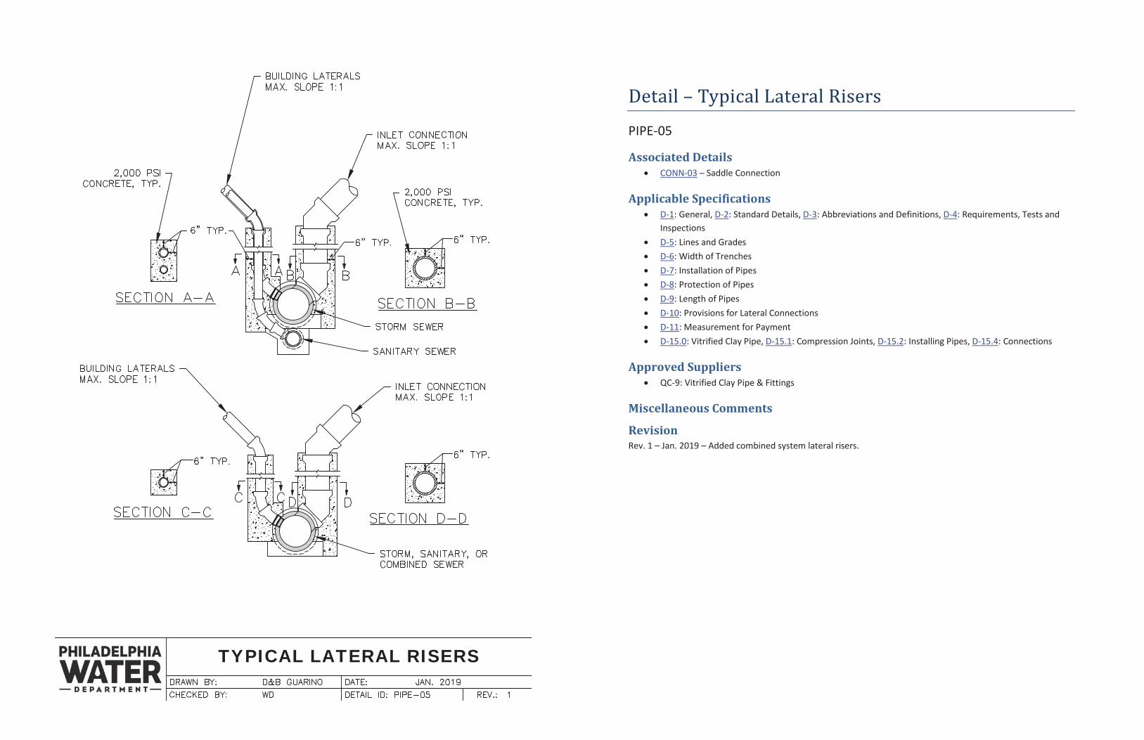
Detail – Typical Lateral Risers
PIPE-05
Associated Details CONN-03 Saddle Connection
Applicable Specifications D-1: General, D-2: Standard Details, D-3: Abbreviations and Definitions, D-4: Requirements, Tests and Inspections D-5: Lines and Grades D-6: Width of Trenches D-7: Installation of Pipes D-8: Protection of Pipes D-9: Length of Pipes D-10: Provisions for Lateral Connections D-11: Measurement for Payment D-15.0: Vitrified Clay Pipe, D-15.1: Compression Joints, D-15.2: Installing Pipes, D-15.4: Connections
Approved Suppliers QC-9: Vitrified Clay Pipe & Fittings
Miscellaneous Comments
Revision Rev. 1 – Jan. 2019 – Added combined system lateral risers.
VIT. CLAY PIPE SEWER WITH R.C.P.STORMWATER CONDUIT TURNOUT
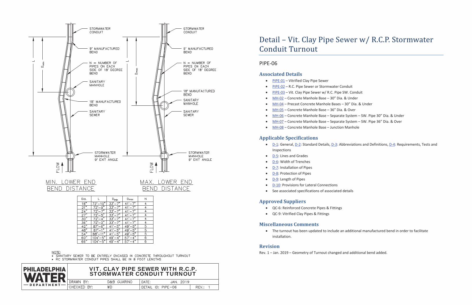
Detail – Vit. Clay Pipe Sewer w/ R.C.P. Stormwater Conduit Turnout
PIPE-06
Associated Details PIPE-01 – Vitrified Clay Pipe Sewer PIPE-02 – R.C. Pipe Sewer or Stormwater Conduit PIPE-03 – Vit. Clay Pipe Sewer w/ R.C. Pipe SW. Conduit MH-02 – Concrete Manhole Base – 30” Dia. & Under MH-04 – Precast Concrete Manhole Bases – 30” Dia. & Under MH-05 – Concrete Manhole Base – 36” Dia. & Over MH-06 – Concrete Manhole Base – Separate System – SW. Pipe 30” Dia. & Under MH-07 – Concrete Manhole Base – Separate System – SW. Pipe 36” Dia. & Over MH-08 – Concrete Manhole Base – Junction Manhole
Applicable Specifications D-1: General, D-2: Standard Details, D-3: Abbreviations and Definitions, D-4: Requirements, Tests and Inspections D-5: Lines and Grades D-6: Width of Trenches D-7: Installation of Pipes D-8: Protection of Pipes D-9: Length of Pipes D-10: Provisions for Lateral Connections See associated specifications of associated details
Approved Suppliers QC-6: Reinforced Concrete Pipes & Fittings QC-9: Vitrified Clay Pipes & Fittings
Miscellaneous Comments The turnout has been updated to include an additional manufactured bend in order to facilitate installation.
Revision Rev. 1 – Jan. 2019 – Geometry of Turnout changed and additional bend added.
CONCRETE COLLAR
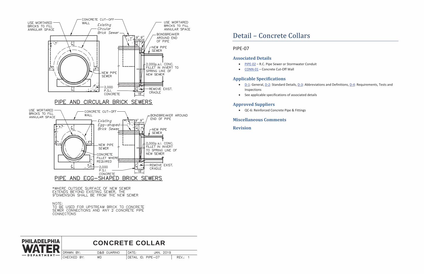
Detail – Concrete Collars
PIPE-07
Associated Details PIPE-02 – R.C. Pipe Sewer or Stormwater Conduit CONN-01 – Concrete Cut-Off Wall
Applicable Specifications D-1: General, D-2: Standard Details, D-3: Abbreviations and Definitions, D-4: Requirements, Tests and Inspections See applicable specifications of associated details
Approved Suppliers QC-6: Reinforced Concrete Pipe & Fittings
Miscellaneous Comments
Revision
EMBANKMENT OVER PIPES
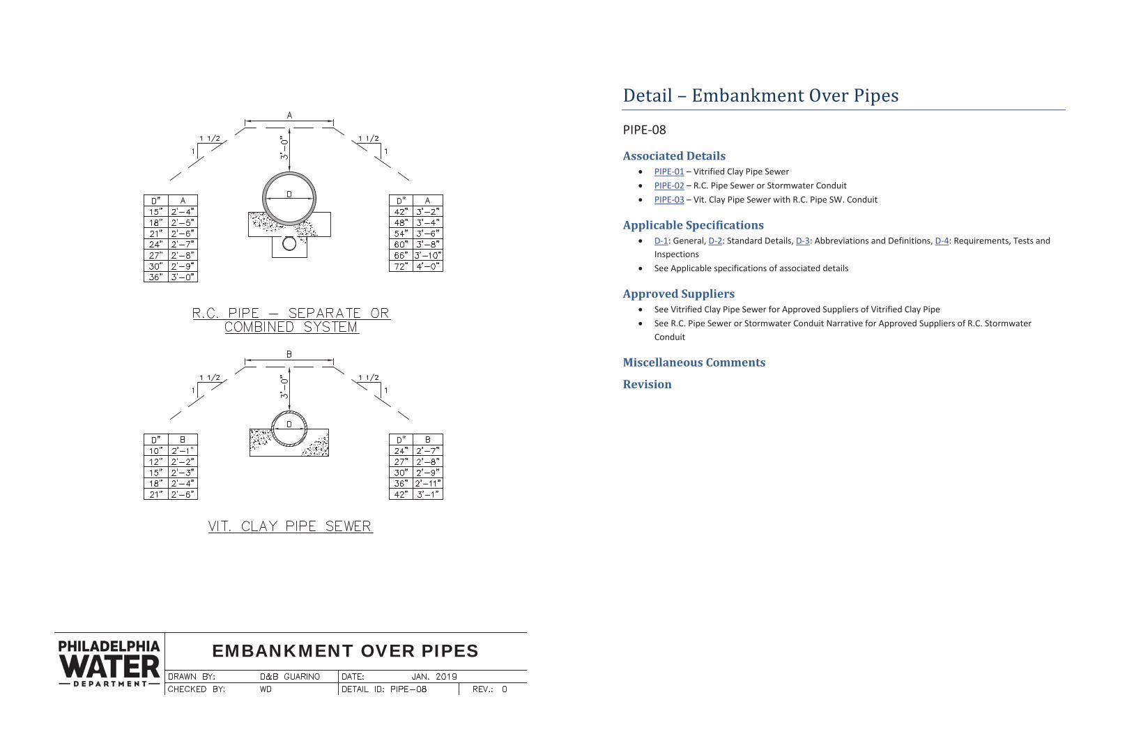
Detail – Embankment Over Pipes
PIPE-08
Associated Details PIPE-01 – Vitrified Clay Pipe Sewer PIPE-02 – R.C. Pipe Sewer or Stormwater Conduit PIPE-03 – Vit. Clay Pipe Sewer with R.C. Pipe SW. Conduit
Applicable Specifications D-1: General, D-2: Standard Details, D-3: Abbreviations and Definitions, D-4: Requirements, Tests and Inspections See Applicable specifications of associated details
Approved Suppliers See Vitrified Clay Pipe Sewer for Approved Suppliers of Vitrified Clay Pipe See R.C. Pipe Sewer or Stormwater Conduit Narrative for Approved Suppliers of R.C. Stormwater Conduit
Miscellaneous Comments
Revision
PIPE ENDWALL
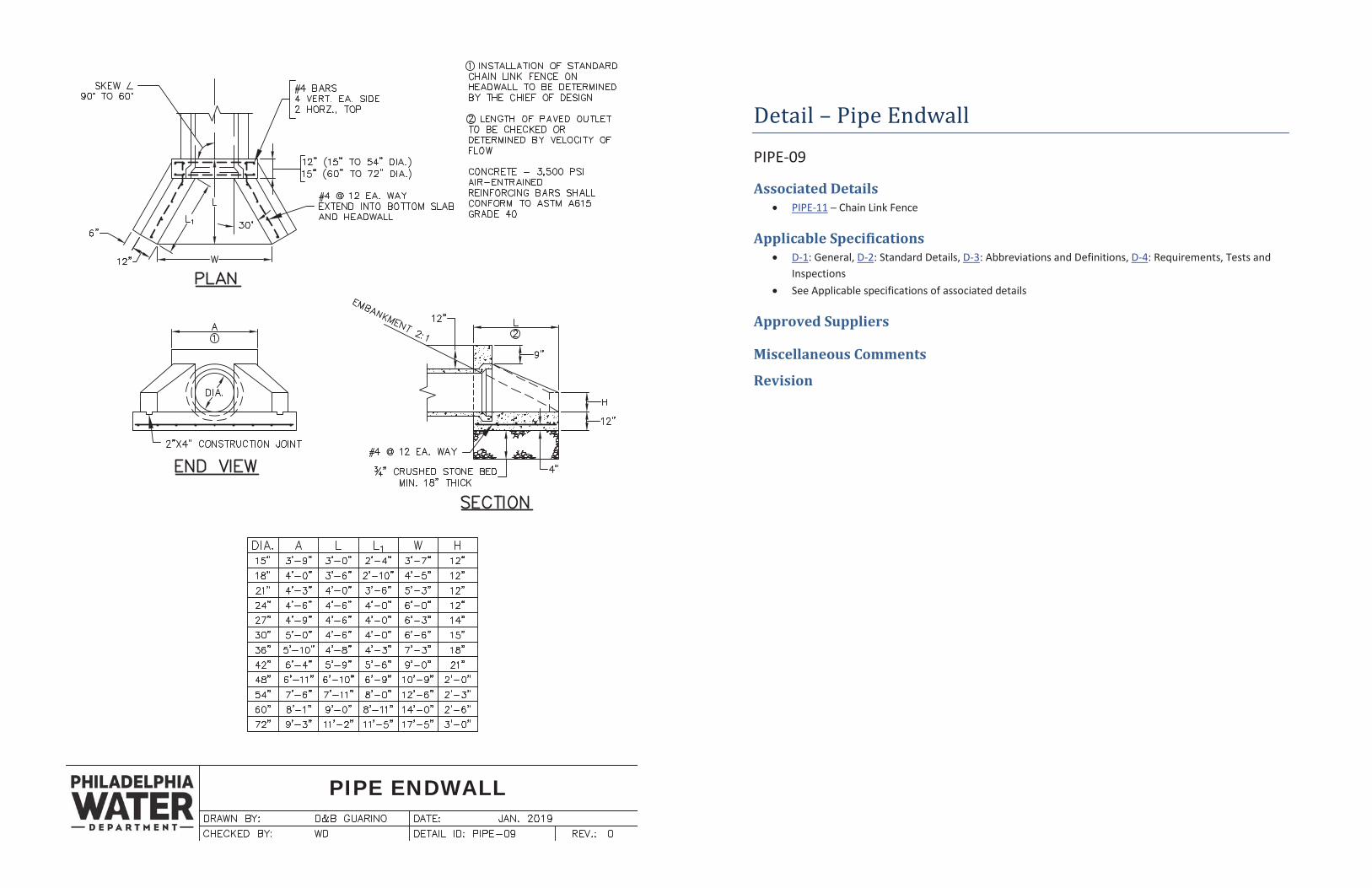
Detail – Pipe Endwall
PIPE-09
Associated Details PIPE-11
Applicable Specifications D-1 D-2 D-3 D-4
Approved Suppliers
Miscellaneous Comments
Revision
PIPE HEADWALL
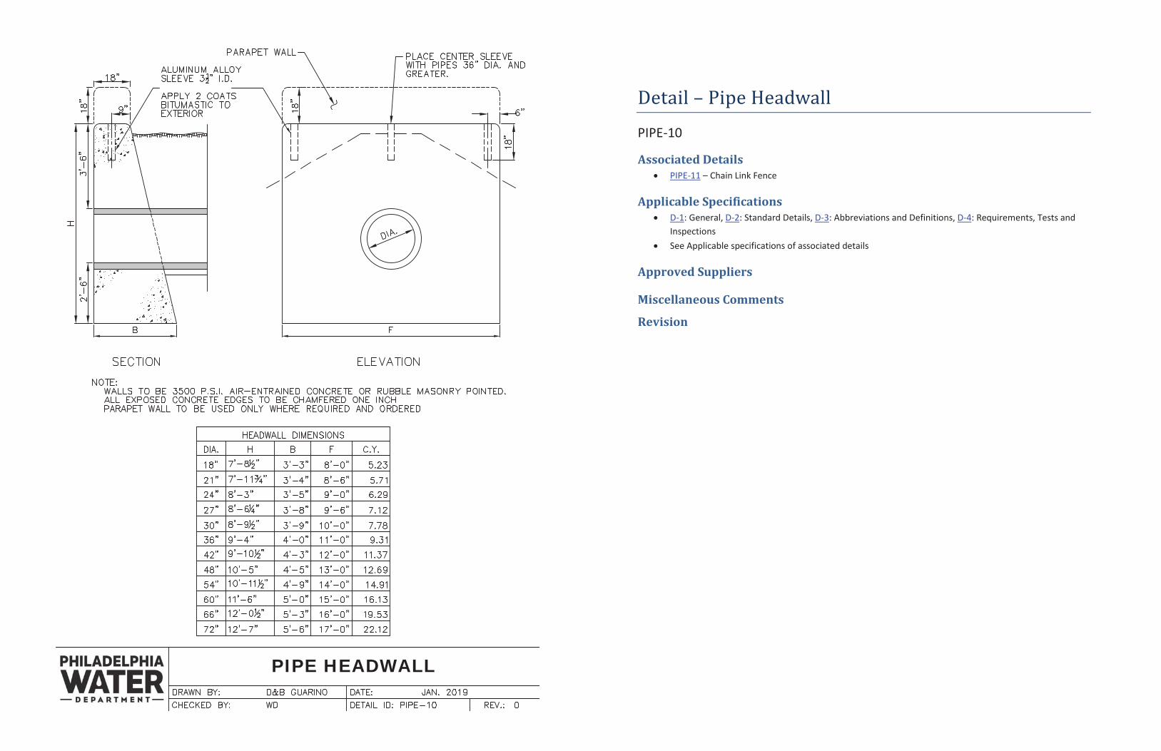
Detail – Pipe Headwall
PIPE-10
Associated Details PIPE-11 – Chain Link Fence
Applicable Specifications D-1: General, D-2: Standard Details, D-3: Abbreviations and Definitions, D-4: Requirements, Tests and Inspections See Applicable specifications of associated details
Approved Suppliers
Miscellaneous Comments
Revision
CHAIN LINK FENCE
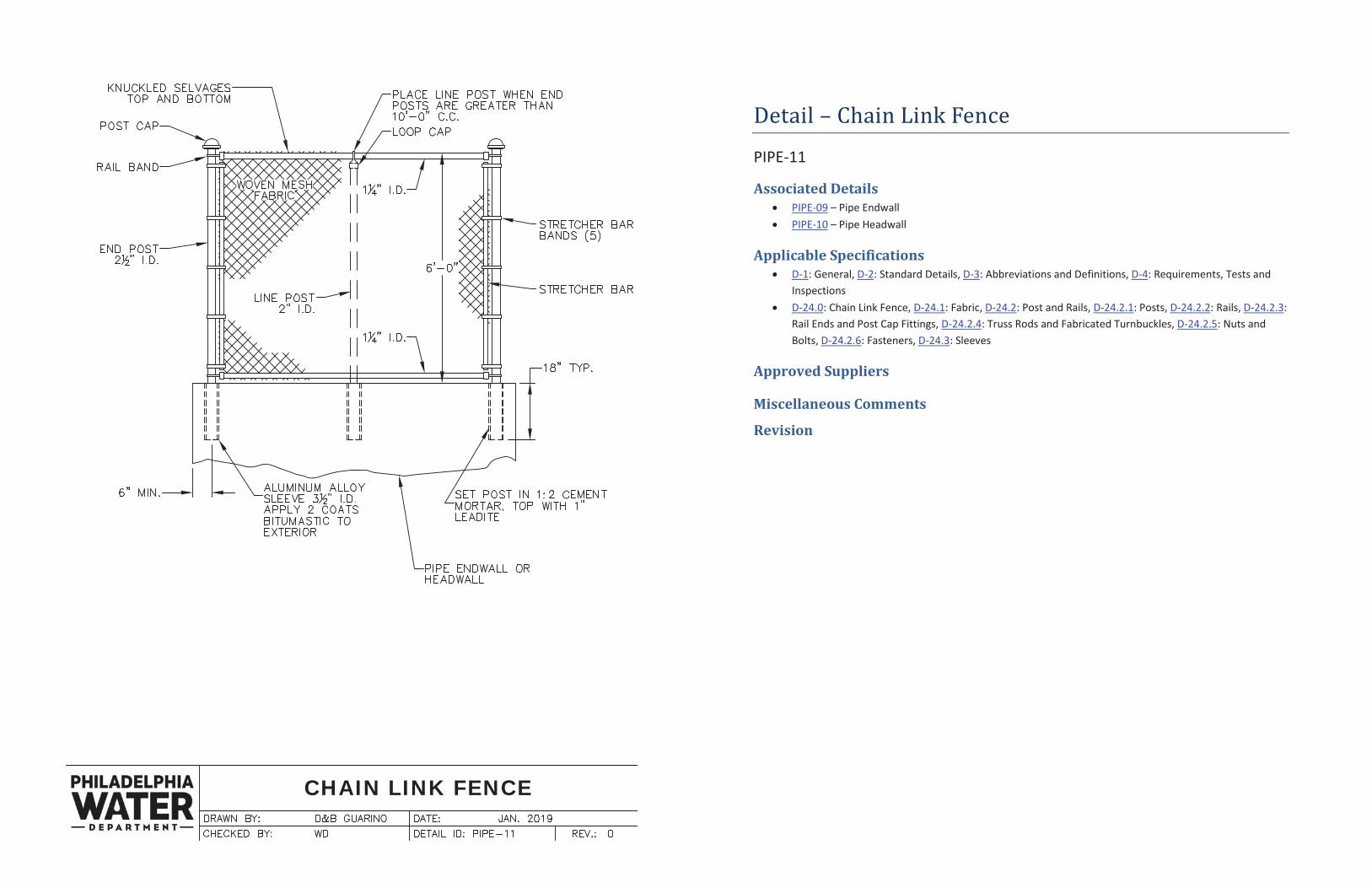
Detail – Chain Link Fence
PIPE-11
Associated Details PIPE-09 – Pipe Endwall PIPE-10 – Pipe Headwall
Applicable Specifications D-1: General, D-2: Standard Details, D-3: Abbreviations and Definitions, D-4: Requirements, Tests and Inspections D-24.0: Chain Link Fence, D-24.1: Fabric, D-24.2: Post and Rails, D-24.2.1: Posts, D-24.2.2: Rails, D-24.2.3: Rail Ends and Post Cap Fittings, D-24.2.4: Truss Rods and Fabricated Turnbuckles, D-24.2.5: Nuts and Bolts, D-24.2.6: Fasteners, D-24.3: Sleeves
Approved Suppliers
Miscellaneous Comments
Revision
CONCRETE CUT-OFF WALL
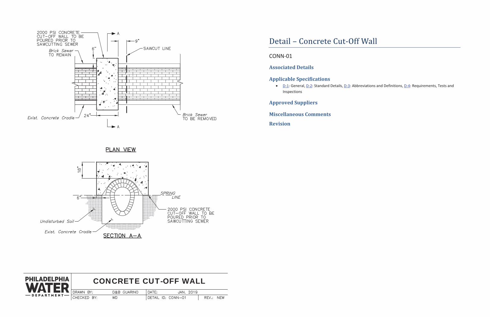
Detail – Concrete Cut-Off Wall
CONN-01
Associated Details
Applicable Specifications D-1: General, D-2: Standard Details, D-3: Abbreviations and Definitions, D-4: Requirements, Tests and Inspections
Approved Suppliers
Miscellaneous Comments
Revision

THIS PAGE INTENTIONALLY LEFT BLANK
CONN-02
THIS PAGE INTENTIONALLY LEFT BLANK
CONN-02
SADDLE CONNECTION
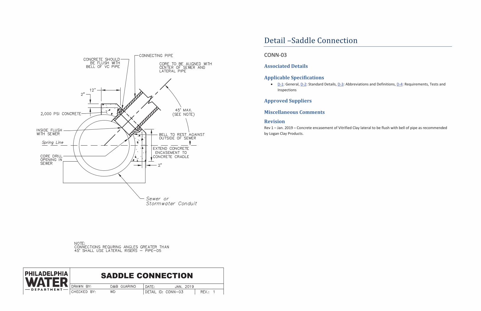
Detail –Saddle Connection CONN-03
Associated Details
Applicable Specifications D-1: General, D-2: Standard Details, D-3: Abbreviations and Definitions, D-4: Requirements, Tests and
Inspections
Approved Suppliers
Miscellaneous Comments
Revision Rev 1 – Jan. 2019 Concrete encasement of Vitrified Clay lateral to be flush with bell of pipe as recommended by Logan Clay Products.
MODIFIED SADDLE CONNECTION TOCIRCULAR BRICK SEWER
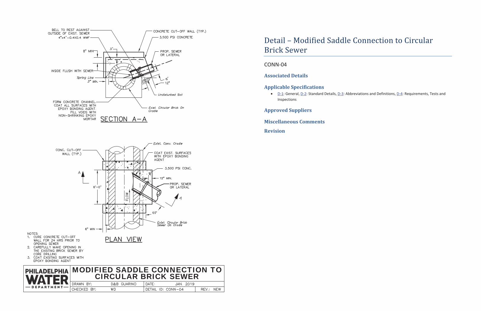
Detail – Modified Saddle Connection to Circular Brick Sewer
CONN-04
Associated Details
Applicable Specifications D-1: General, D-2: Standard Details, D-3: Abbreviations and Definitions, D-4: Requirements, Tests and Inspections
Approved Suppliers
Miscellaneous Comments
Revision
MODIFIED SADDLE CONNECTION TOEGG-SHAPED BRICK SEWER
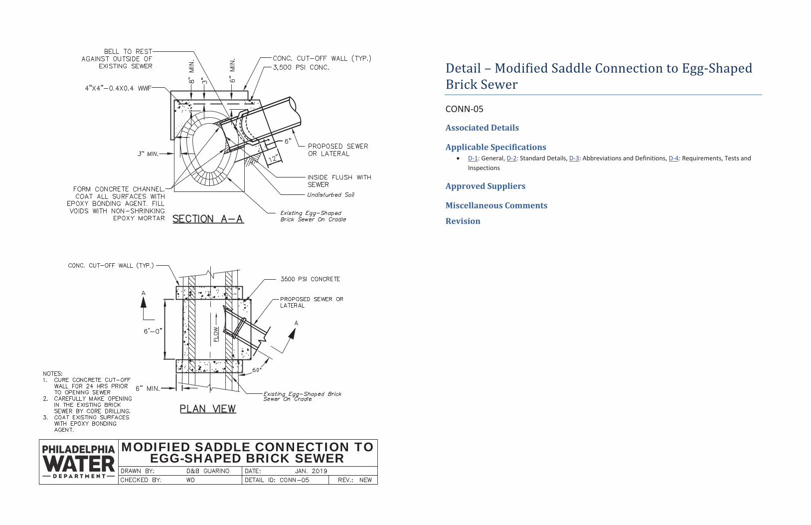
Detail – Modified Saddle Connection to Egg-Shaped Brick Sewer
CONN-05
Associated Details
Applicable Specifications D-1: General, D-2: Standard Details, D-3: Abbreviations and Definitions, D-4: Requirements, Tests and Inspections
Approved Suppliers
Miscellaneous Comments
Revision
DOGHOUSE MANHOLE CONNECTIONFOR EXISTING 2'-0" & 2'-6" BRICK SEWER AND PROPOSED
RCP 24" OR SMALLER
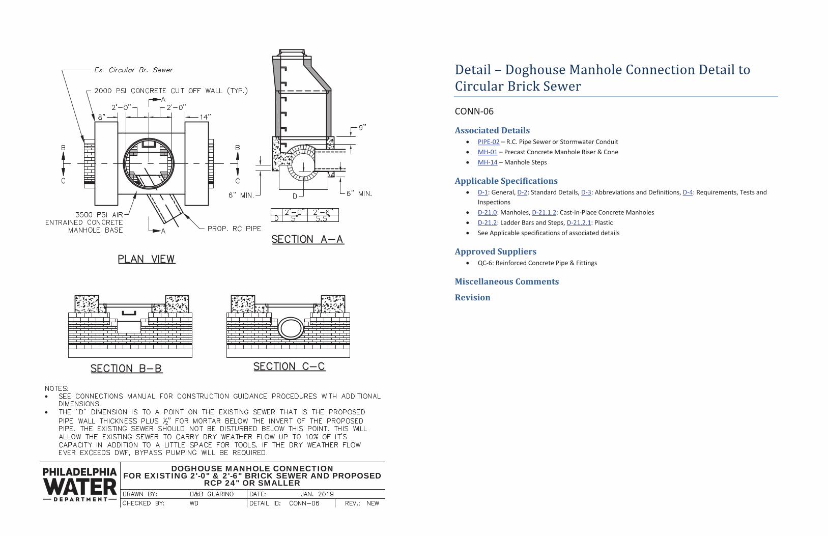
Detail – Doghouse Manhole Connection Detail to Circular Brick Sewer
CONN-06
Associated Details PIPE-02 – R.C. Pipe Sewer or Stormwater Conduit MH-01 – Precast Concrete Manhole Riser & Cone MH-14 – Manhole Steps
Applicable Specifications D-1: General, D-2: Standard Details, D-3: Abbreviations and Definitions, D-4: Requirements, Tests and Inspections D-21.0: Manholes, D-21.1.2: Cast-in-Place Concrete Manholes D-21.2: Ladder Bars and Steps, D-21.2.1: Plastic See Applicable specifications of associated details
Approved Suppliers QC-6: Reinforced Concrete Pipe & Fittings
Miscellaneous Comments
Revision
A
A
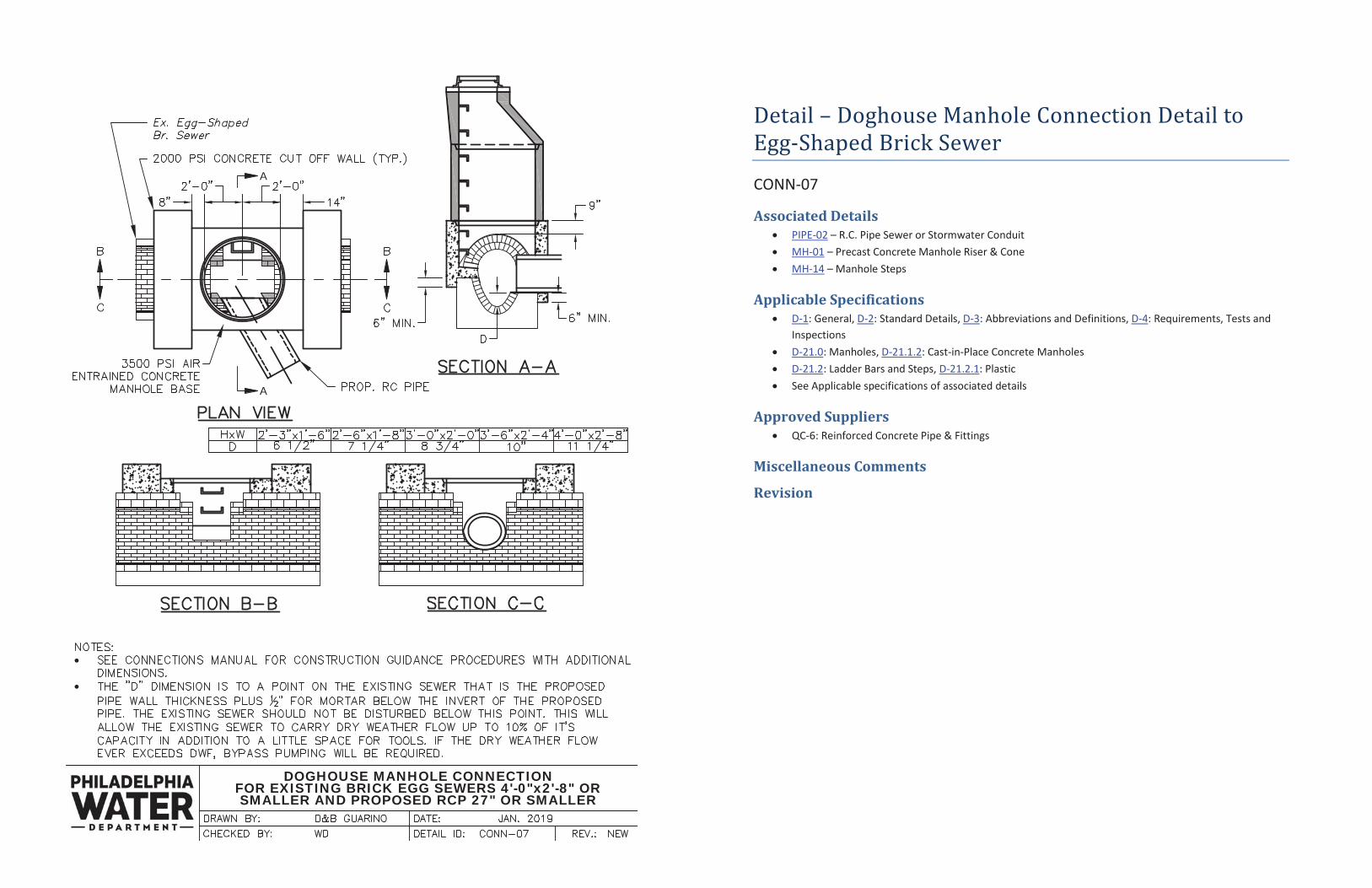
DOGHOUSE MANHOLE CONNECTIONFOR EXISTING BRICK EGG SEWERS 4'-0"x2'-8" ORSMALLER AND PROPOSED RCP 27" OR SMALLER
Detail – Doghouse Manhole Connection Detail to Egg-Shaped Brick Sewer
CONN-07
Associated Details PIPE-02 – R.C. Pipe Sewer or Stormwater Conduit MH-01 – Precast Concrete Manhole Riser & Cone MH-14 – Manhole Steps
Applicable Specifications D-1: General, D-2: Standard Details, D-3: Abbreviations and Definitions, D-4: Requirements, Tests and Inspections D-21.0: Manholes, D-21.1.2: Cast-in-Place Concrete Manholes D-21.2: Ladder Bars and Steps, D-21.2.1: Plastic See Applicable specifications of associated details
Approved Suppliers QC-6: Reinforced Concrete Pipe & Fittings
Miscellaneous Comments
Revision
COMBINED SYSTEM VENTCONNECTION
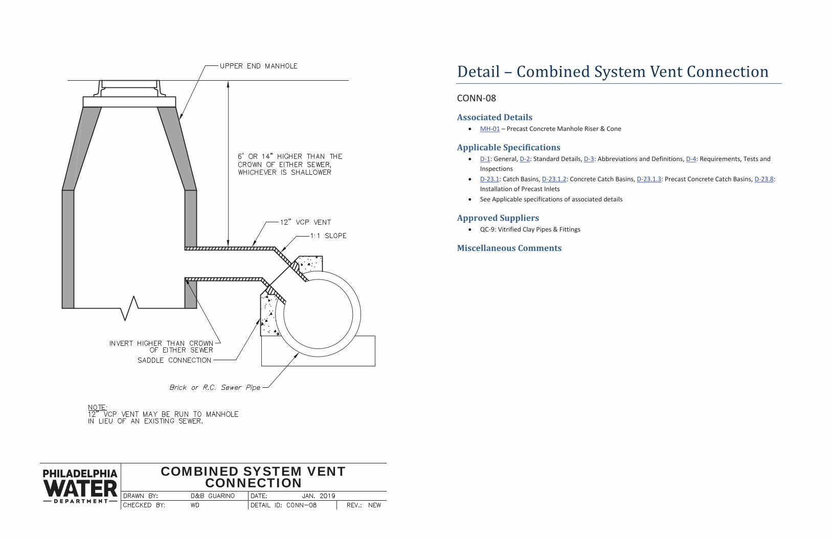
Detail – Combined System Vent Connection CONN-08
Associated Details MH-01 – Precast Concrete Manhole Riser & Cone
Applicable Specifications D-1: General, D-2: Standard Details, D-3: Abbreviations and Definitions, D-4: Requirements, Tests and Inspections D-23.1: Catch Basins, D-23.1.2: Concrete Catch Basins, D-23.1.3: Precast Concrete Catch Basins, D-23.8: Installation of Precast Inlets See Applicable specifications of associated details
Approved Suppliers QC-9: Vitrified Clay Pipes & Fittings
Miscellaneous Comments
PRECAST CONCRETE MANHOLERISER AND CONE
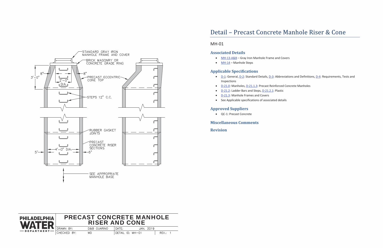
Detail – Precast Concrete Manhole Riser & Cone
MH-01
Associated Details MH-13-A&B – Gray Iron Manhole Frame and Covers MH-14 – Manhole Steps
Applicable Specifications D-1: General, D-2: Standard Details, D-3: Abbreviations and Definitions, D-4: Requirements, Tests and Inspections D-21.0: Manholes, D-21.1.3: Precast Reinforced Concrete Manholes D-21.2: Ladder Bars and Steps, D-21.2.1: Plastic D-21.3: Manhole Frames and Covers See Applicable specifications of associated details
Approved Suppliers QC-1: Precast Concrete
Miscellaneous Comments
Revision

CONCRETE MANHOLE BASE30" DIA. AND UNDER
Detail – Concrete Manhole Base – 30” Dia. & Under
MH-02
Associated Details PIPE-01 – Vitrified Clay Pipe Sewer PIPE-02 – R.C. Pipe Sewer or Stormwater Conduit MH-01 – Precast Concrete Manhole Riser and Cone
Applicable Specifications D-1: General, D-2: Standard Details, D-3: Abbreviations and Definitions, D-4: Requirements, Tests and Inspections D-21.0: Manholes, D-21.1.2: Cast-in-Place Concrete Manholes See applicable specifications of associated details
Approved Suppliers
Miscellaneous Comments
Revision
DOGHOUSE MANHOLE ON30" & UNDER SEWER
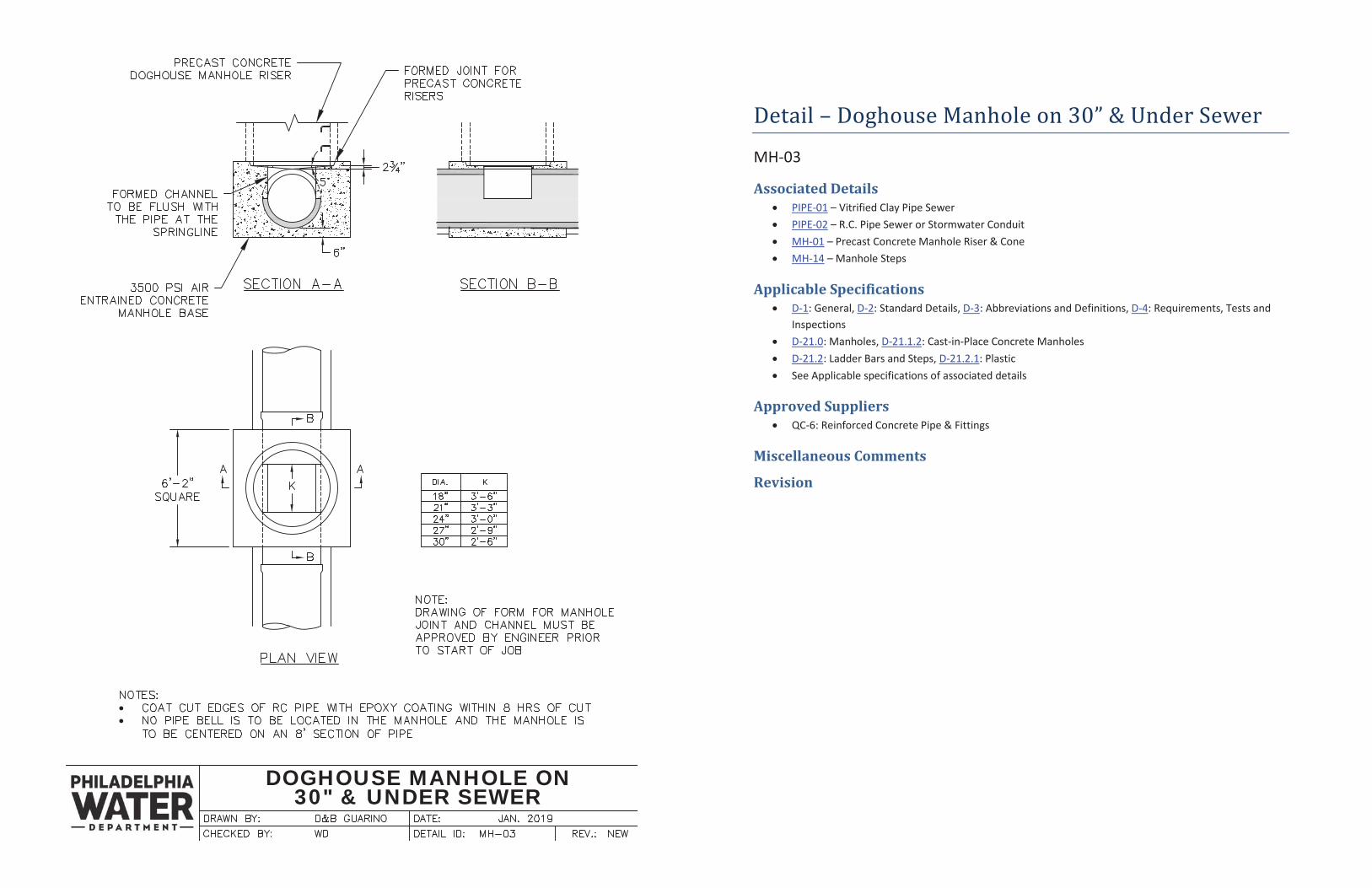
Detail – Doghouse Manhole on 30” & Under Sewer
MH-03
Associated Details PIPE-01 – Vitrified Clay Pipe Sewer PIPE-02 – R.C. Pipe Sewer or Stormwater Conduit MH-01 – Precast Concrete Manhole Riser & Cone MH-14 – Manhole Steps
Applicable Specifications D-1: General, D-2: Standard Details, D-3: Abbreviations and Definitions, D-4: Requirements, Tests and Inspections D-21.0: Manholes, D-21.1.2: Cast-in-Place Concrete Manholes D-21.2: Ladder Bars and Steps, D-21.2.1: Plastic See Applicable specifications of associated details
Approved Suppliers QC-6: Reinforced Concrete Pipe & Fittings
Miscellaneous Comments
Revision
PRECAST CONCRETE MANHOLEBASES - 30" DIA. AND UNDER
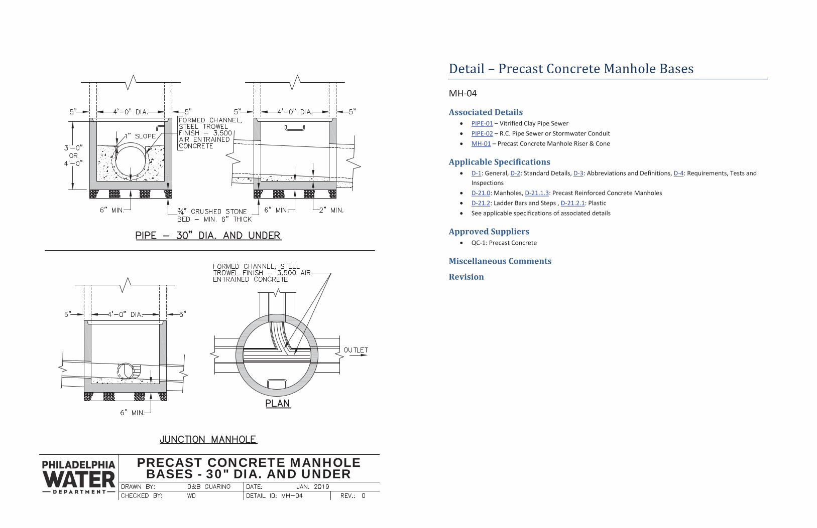
Detail – Precast Concrete Manhole Bases
MH-04
Associated Details PIPE-01 – Vitrified Clay Pipe Sewer PIPE-02 – R.C. Pipe Sewer or Stormwater Conduit MH-01 – Precast Concrete Manhole Riser & Cone
Applicable Specifications D-1: General, D-2: Standard Details, D-3: Abbreviations and Definitions, D-4: Requirements, Tests and Inspections D-21.0: Manholes, D-21.1.3: Precast Reinforced Concrete Manholes D-21.2: Ladder Bars and Steps , D-21.2.1: Plastic See applicable specifications of associated details
Approved Suppliers QC-1: Precast Concrete
Miscellaneous Comments
Revision
CONCRETE MANHOLE BASE36" DIA. AND OVER
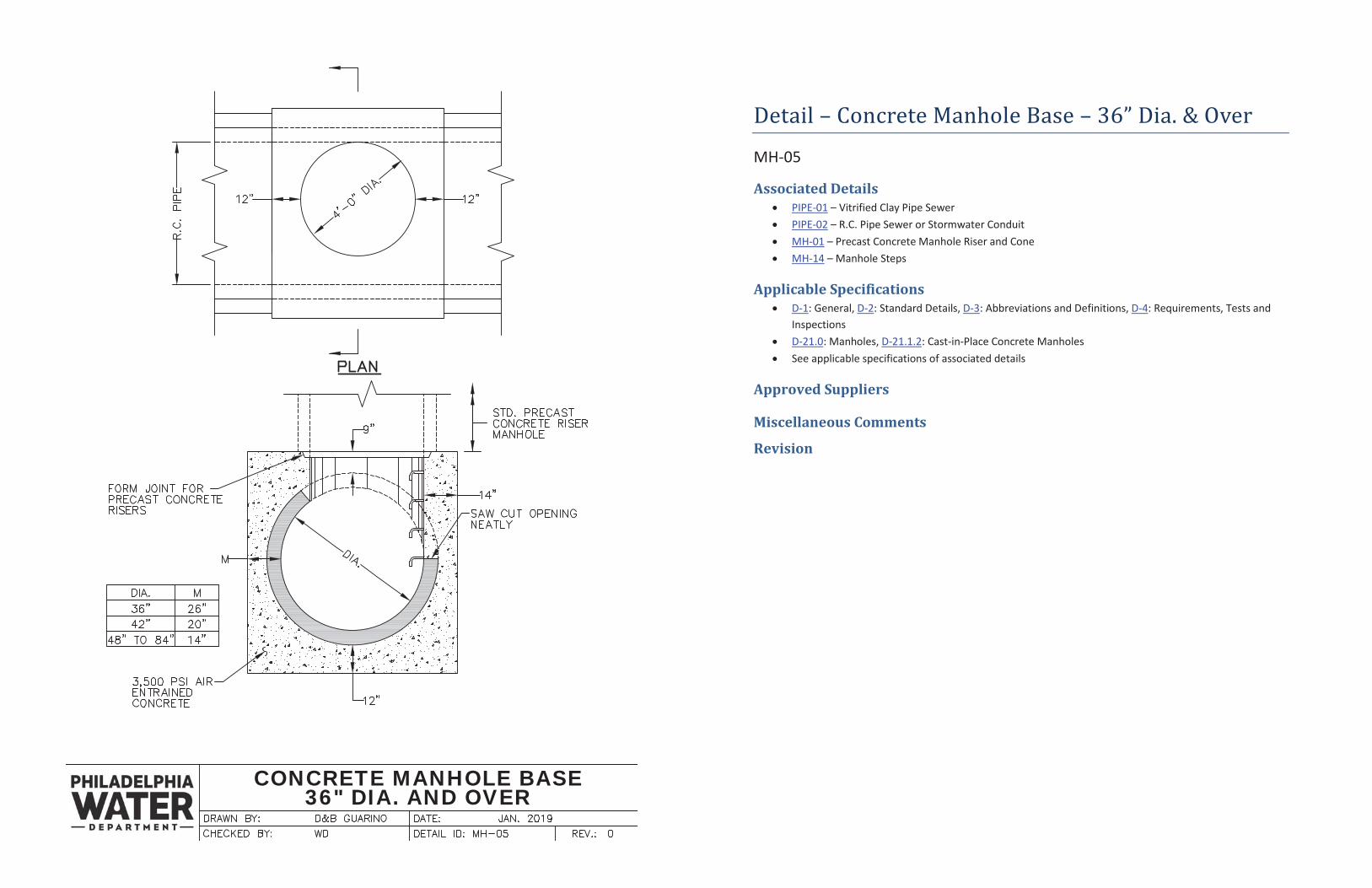
Detail – Concrete Manhole Base – 36” Dia. & Over
MH-05
Associated Details PIPE-01 – Vitrified Clay Pipe Sewer PIPE-02 – R.C. Pipe Sewer or Stormwater Conduit MH-01 – Precast Concrete Manhole Riser and Cone MH-14 – Manhole Steps
Applicable Specifications D-1: General, D-2: Standard Details, D-3: Abbreviations and Definitions, D-4: Requirements, Tests and Inspections D-21.0: Manholes, D-21.1.2: Cast-in-Place Concrete Manholes See applicable specifications of associated details
Approved Suppliers
Miscellaneous Comments
Revision
CONCRETE MANHOLE BASE - SEPARATE SYSTEMSTORMWATER PIPE 30" DIA. AND UNDER
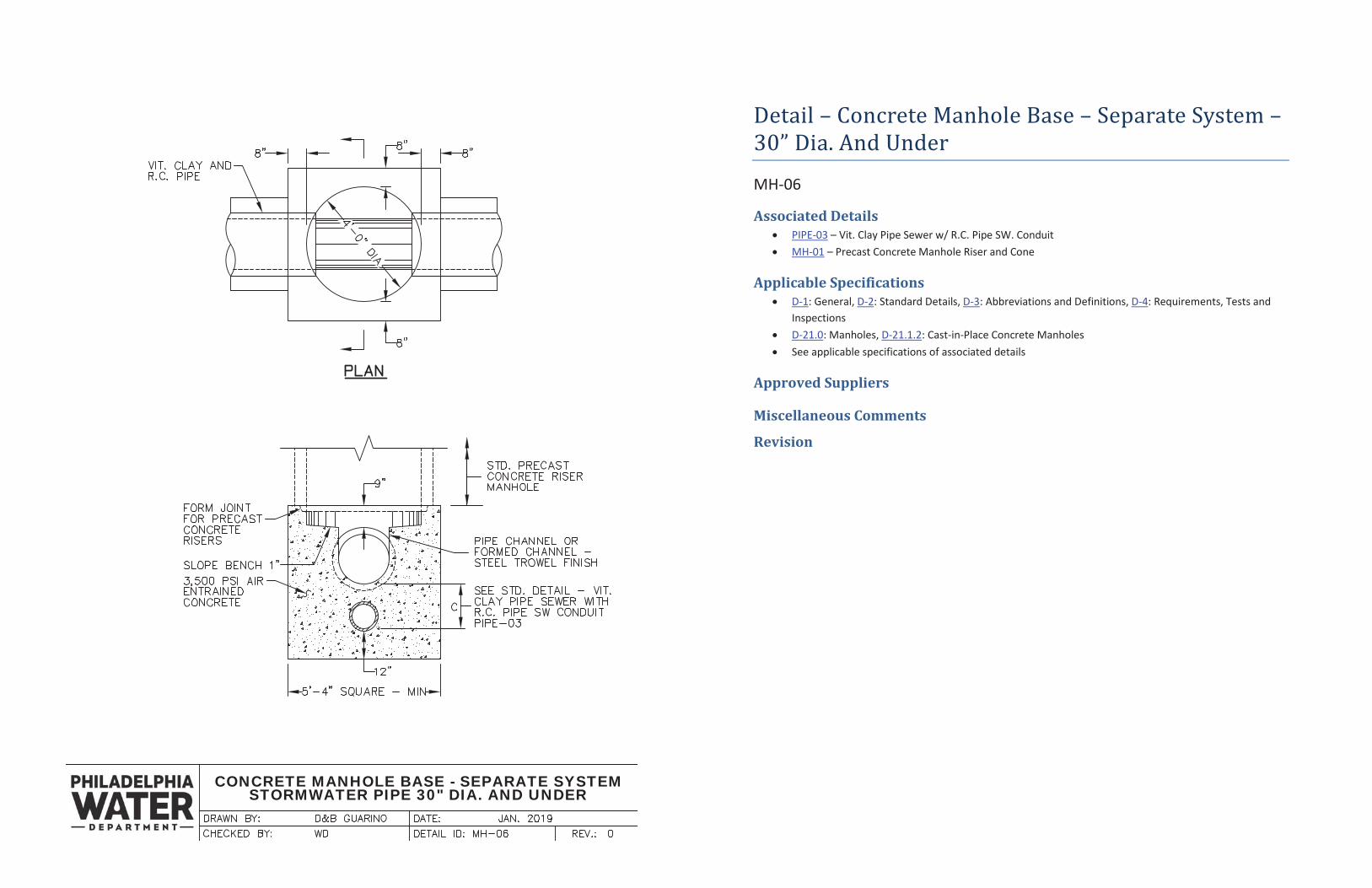
Detail – Concrete Manhole Base – Separate System – 30” Dia. And Under
MH-06
Associated Details PIPE-03 – Vit. Clay Pipe Sewer w/ R.C. Pipe SW. Conduit MH-01 – Precast Concrete Manhole Riser and Cone
Applicable Specifications D-1: General, D-2: Standard Details, D-3: Abbreviations and Definitions, D-4: Requirements, Tests and Inspections D-21.0: Manholes, D-21.1.2: Cast-in-Place Concrete Manholes See applicable specifications of associated details
Approved Suppliers
Miscellaneous Comments
Revision
CONCRETE MANHOLE BASE - SEPARATE SYSTEMSTORMWATER PIPE 36" DIA. AND OVER
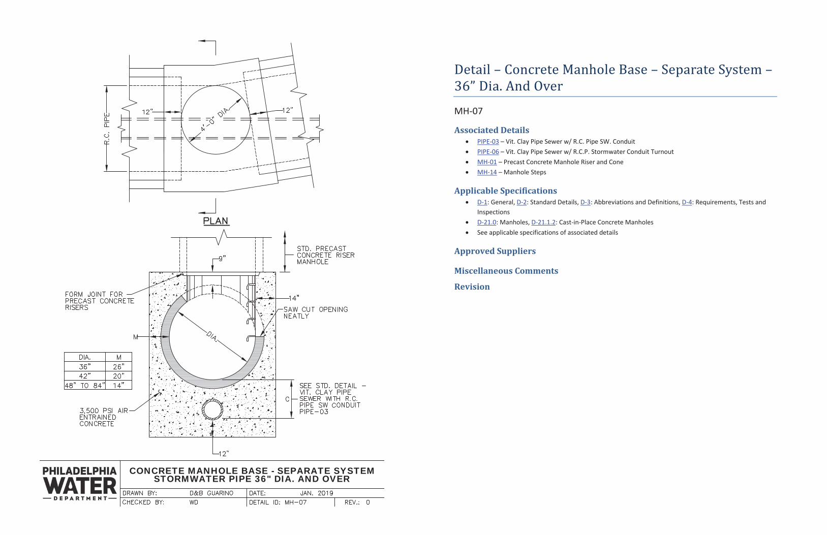
Detail – Concrete Manhole Base – Separate System – 36” Dia. And Over
MH-07
Associated Details PIPE-03 – Vit. Clay Pipe Sewer w/ R.C. Pipe SW. Conduit PIPE-06 – Vit. Clay Pipe Sewer w/ R.C.P. Stormwater Conduit Turnout MH-01 – Precast Concrete Manhole Riser and Cone MH-14 – Manhole Steps
Applicable Specifications D-1: General, D-2: Standard Details, D-3: Abbreviations and Definitions, D-4: Requirements, Tests and Inspections D-21.0: Manholes, D-21.1.2: Cast-in-Place Concrete Manholes See applicable specifications of associated details
Approved Suppliers
Miscellaneous Comments
Revision
CONCRETE MANHOLE BASEJUNCTION MANHOLE
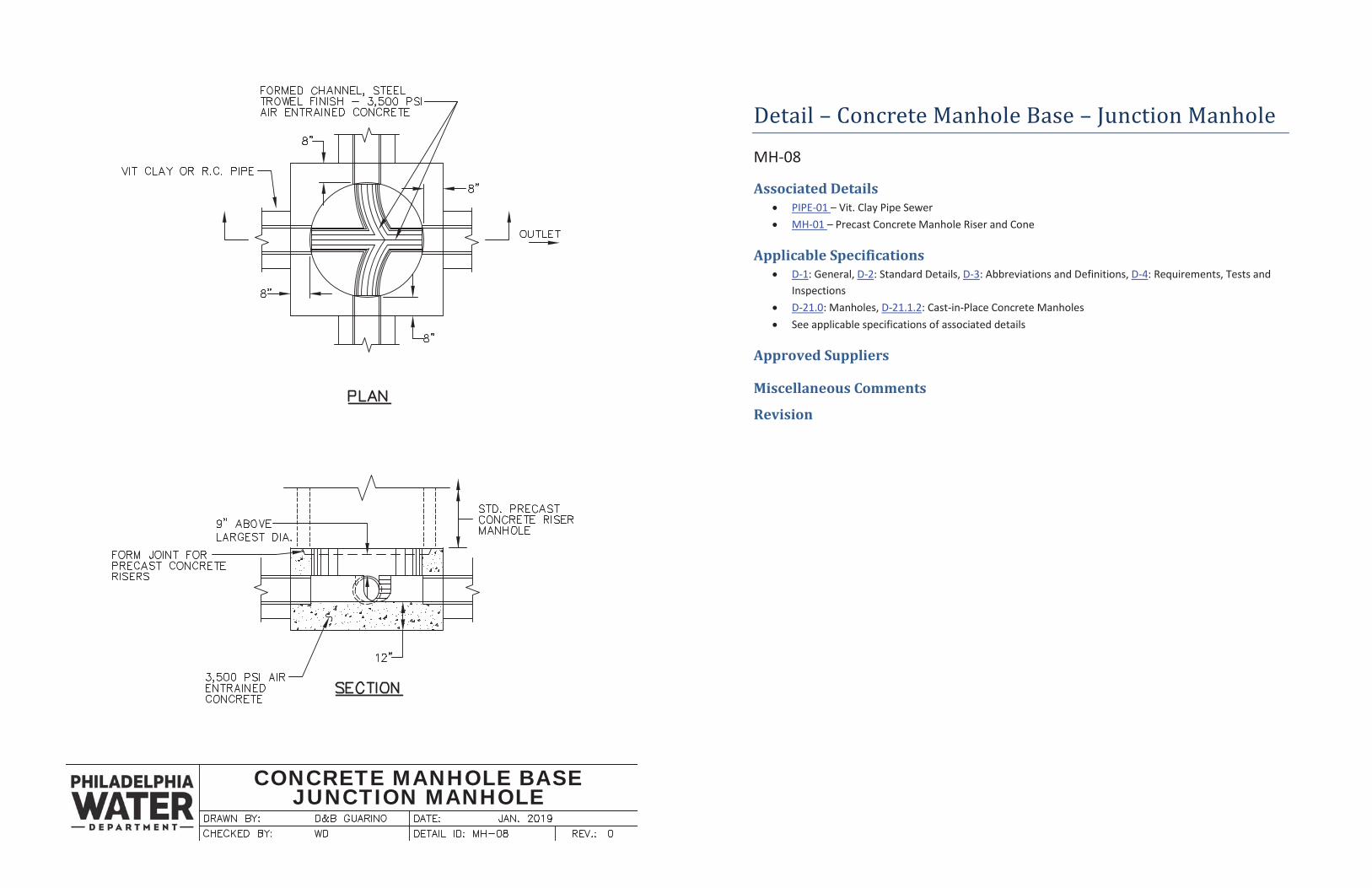
Detail – Concrete Manhole Base – Junction Manhole
MH-08
Associated Details PIPE-01 – Vit. Clay Pipe Sewer MH-01 – Precast Concrete Manhole Riser and Cone
Applicable Specifications D-1: General, D-2: Standard Details, D-3: Abbreviations and Definitions, D-4: Requirements, Tests and Inspections D-21.0: Manholes, D-21.1.2: Cast-in-Place Concrete Manholes See applicable specifications of associated details
Approved Suppliers
Miscellaneous Comments
Revision
SUMMIT MANHOLE
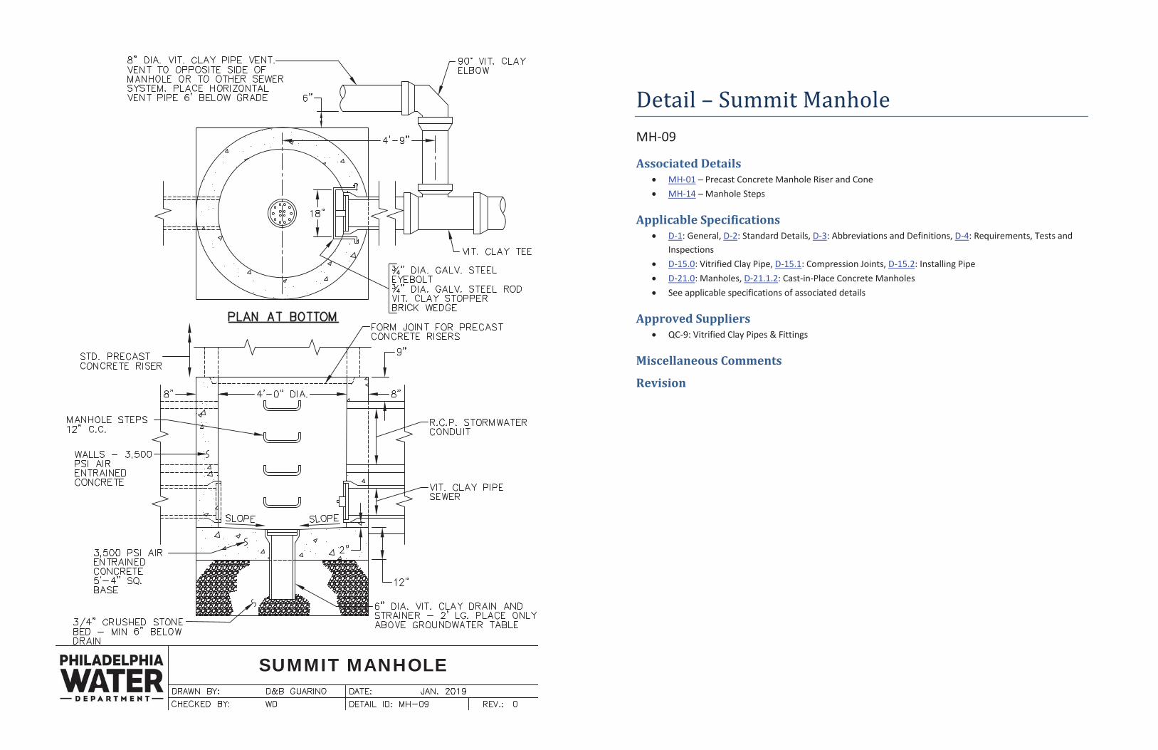
Detail – Summit Manhole MH-09
Associated Details MH-01 Precast Concrete Manhole Riser and Cone MH-14 Manhole Steps
Applicable Specifications D-1: General, D-2: Standard Details, D-3: Abbreviations and Definitions, D-4: Requirements, Tests and Inspections D-15.0: Vitrified Clay Pipe, D-15.1: Compression Joints, D-15.2: Installing Pipe D-21.0: Manholes, D-21.1.2: Cast-in-Place Concrete Manholes See applicable specifications of associated details
Approved Suppliers QC-9: Vitrified Clay Pipes & Fittings
Miscellaneous Comments
Revision
PRECAST CONCRETE DROPMANHOLE
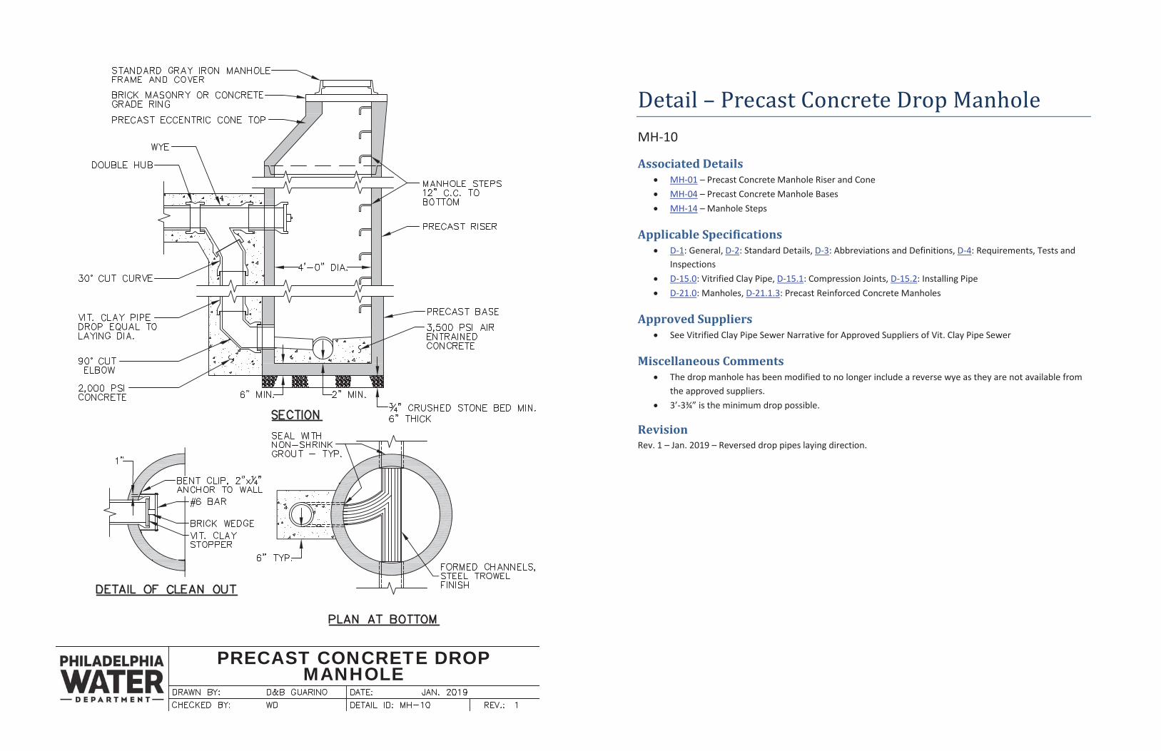
Detail – Precast Concrete Drop Manhole MH-10
Associated Details MH-01 – Precast Concrete Manhole Riser and Cone MH-04 – Precast Concrete Manhole Bases MH-14 – Manhole Steps
Applicable Specifications D-1: General, D-2: Standard Details, D-3: Abbreviations and Definitions, D-4: Requirements, Tests and Inspections D-15.0: Vitrified Clay Pipe, D-15.1: Compression Joints, D-15.2: Installing Pipe D-21.0: Manholes, D-21.1.3: Precast Reinforced Concrete Manholes
Approved Suppliers See Vitrified Clay Pipe Sewer Narrative for Approved Suppliers of Vit. Clay Pipe Sewer
Miscellaneous Comments The drop manhole has been modified to no longer include a reverse wye as they are not available from the approved suppliers. 3’-3¾” is the minimum drop possible.
Revision Rev. 1 – Jan. 2019 – Reversed drop pipes laying direction.
PRECAST CONCRETE INTERIORDROP MANHOLE
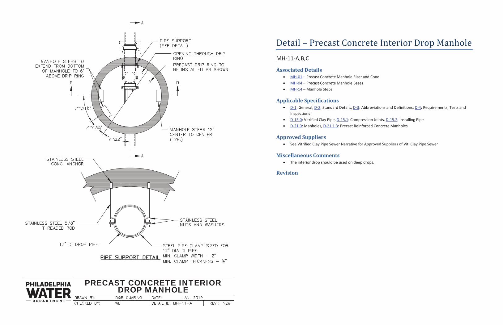
Detail – Precast Concrete Interior Drop Manhole MH-11-A,B,C
Associated Details MH-01 – Precast Concrete Manhole Riser and Cone MH-04 – Precast Concrete Manhole Bases MH-14 – Manhole Steps
Applicable Specifications D-1: General, D-2: Standard Details, D-3: Abbreviations and Definitions, D-4: Requirements, Tests and Inspections D-15.0: Vitrified Clay Pipe, D-15.1: Compression Joints, D-15.2: Installing Pipe D-21.0: Manholes, D-21.1.3: Precast Reinforced Concrete Manholes
Approved Suppliers See Vitrified Clay Pipe Sewer Narrative for Approved Suppliers of Vit. Clay Pipe Sewer
Miscellaneous Comments The interior drop should be used on deep drops.
Revision
PRECAST CONCRETE INTERIORDROP MANHOLE
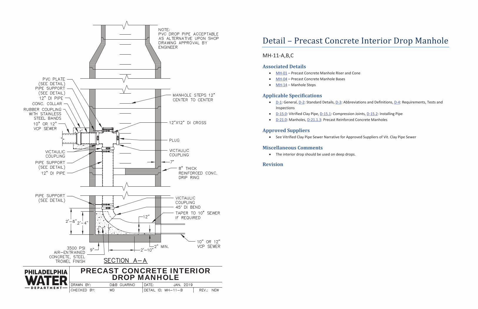
Detail – Precast Concrete Interior Drop Manhole MH-11-A,B,C
Associated Details MH-01 – Precast Concrete Manhole Riser and Cone MH-04 – Precast Concrete Manhole Bases MH-14 – Manhole Steps
Applicable Specifications D-1: General, D-2: Standard Details, D-3: Abbreviations and Definitions, D-4: Requirements, Tests and Inspections D-15.0: Vitrified Clay Pipe, D-15.1: Compression Joints, D-15.2: Installing Pipe D-21.0: Manholes, D-21.1.3: Precast Reinforced Concrete Manholes
Approved Suppliers See Vitrified Clay Pipe Sewer Narrative for Approved Suppliers of Vit. Clay Pipe Sewer
Miscellaneous Comments The interior drop should be used on deep drops.
Revision
PRECAST CONCRETE INTERIORDROP MANHOLE
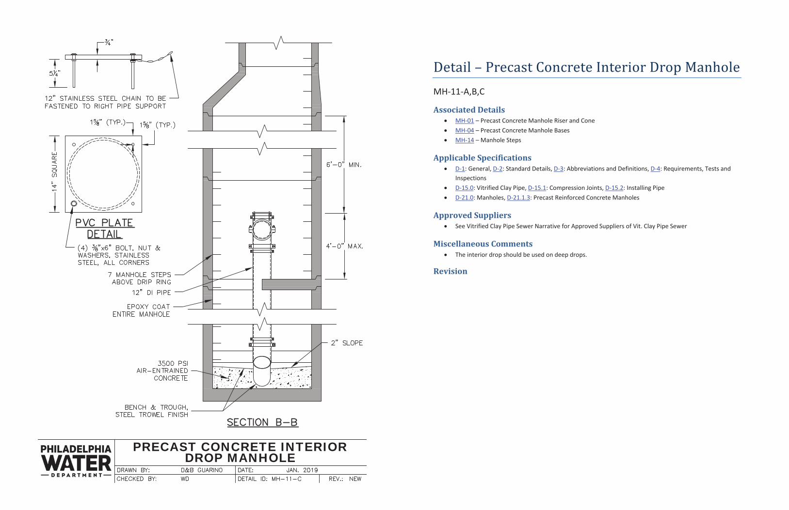
Detail – Precast Concrete Interior Drop Manhole MH-11-A,B,C
Associated Details MH-01 – Precast Concrete Manhole Riser and Cone MH-04 – Precast Concrete Manhole Bases MH-14 – Manhole Steps
Applicable Specifications D-1: General, D-2: Standard Details, D-3: Abbreviations and Definitions, D-4: Requirements, Tests and Inspections D-15.0: Vitrified Clay Pipe, D-15.1: Compression Joints, D-15.2: Installing Pipe D-21.0: Manholes, D-21.1.3: Precast Reinforced Concrete Manholes
Approved Suppliers See Vitrified Clay Pipe Sewer Narrative for Approved Suppliers of Vit. Clay Pipe Sewer
Miscellaneous Comments The interior drop should be used on deep drops.
Revision
WELLHOLE
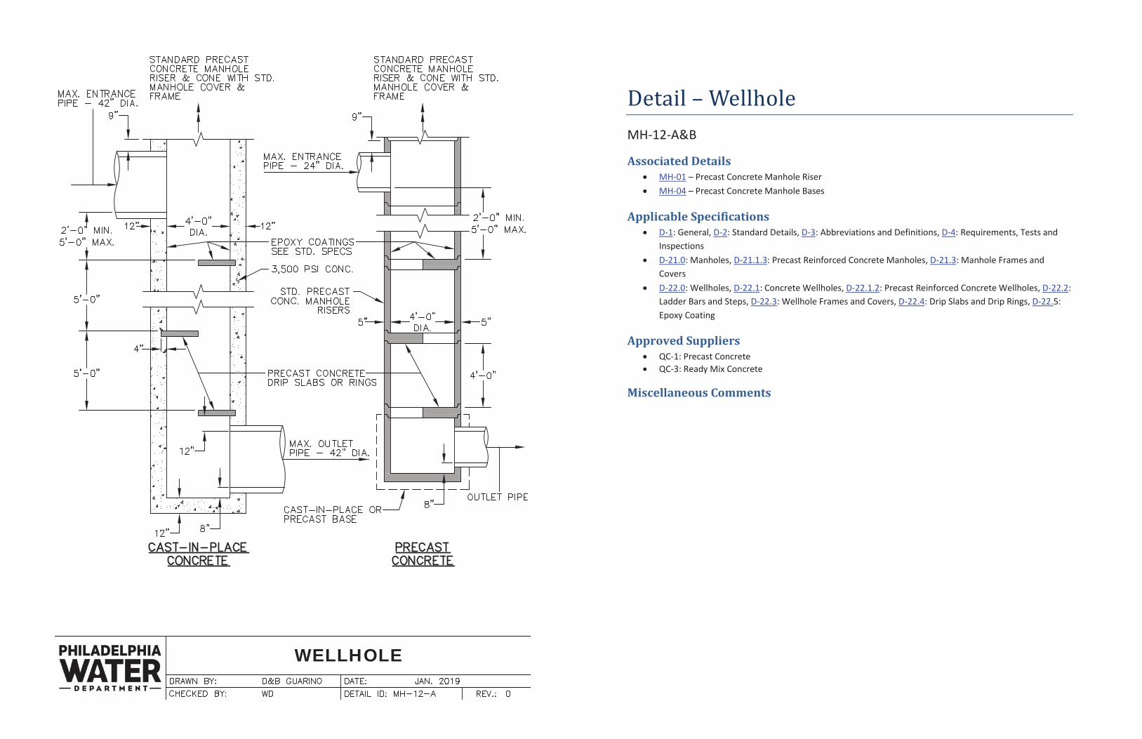
Detail – Wellhole MH-12-A&B
Associated Details MH-01 – Precast Concrete Manhole Riser MH-04 – Precast Concrete Manhole Bases
Applicable Specifications D-1: General, D-2: Standard Details, D-3: Abbreviations and Definitions, D-4: Requirements, Tests and Inspections D-21.0: Manholes, D-21.1.3: Precast Reinforced Concrete Manholes, D-21.3: Manhole Frames and Covers D-22.0: Wellholes, D-22.1: Concrete Wellholes, D-22.1.2: Precast Reinforced Concrete Wellholes, D-22.2: Ladder Bars and Steps, D-22.3: Wellhole Frames and Covers, D-22.4: Drip Slabs and Drip Rings, D-22.5: Epoxy Coating
Approved Suppliers QC-1: Precast Concrete QC-3: Ready Mix Concrete
Miscellaneous Comments
WELLHOLE
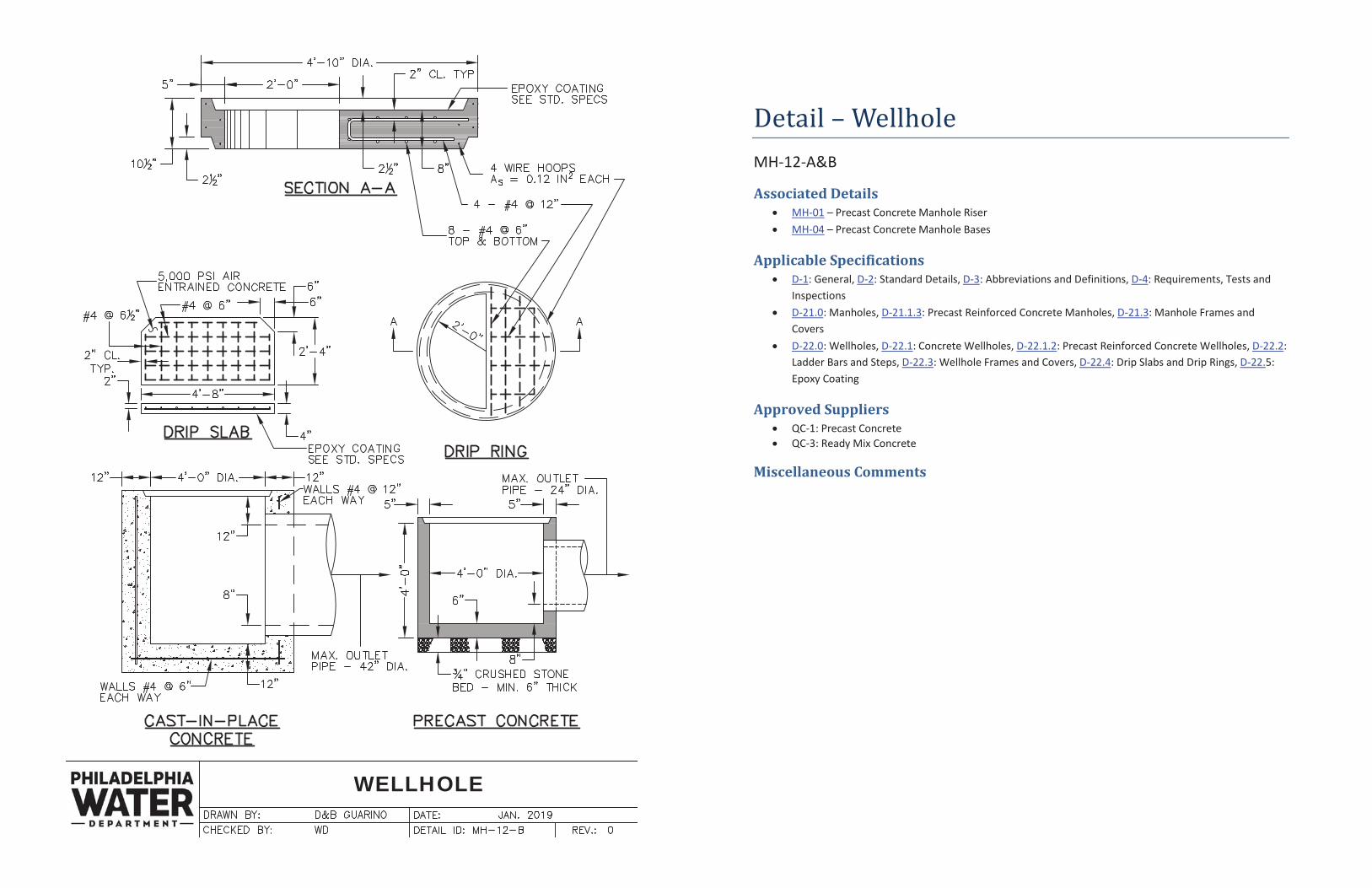
Detail – Wellhole MH-12-A&B
Associated Details MH-01 – Precast Concrete Manhole Riser MH-04 – Precast Concrete Manhole Bases
Applicable Specifications D-1: General, D-2: Standard Details, D-3: Abbreviations and Definitions, D-4: Requirements, Tests and Inspections D-21.0: Manholes, D-21.1.3: Precast Reinforced Concrete Manholes, D-21.3: Manhole Frames and Covers D-22.0: Wellholes, D-22.1: Concrete Wellholes, D-22.1.2: Precast Reinforced Concrete Wellholes, D-22.2: Ladder Bars and Steps, D-22.3: Wellhole Frames and Covers, D-22.4: Drip Slabs and Drip Rings, D-22.5: Epoxy Coating
Approved Suppliers QC-1: Precast Concrete QC-3: Ready Mix Concrete
Miscellaneous Comments
GRAY IRON MANHOLEFRAME & COVERS
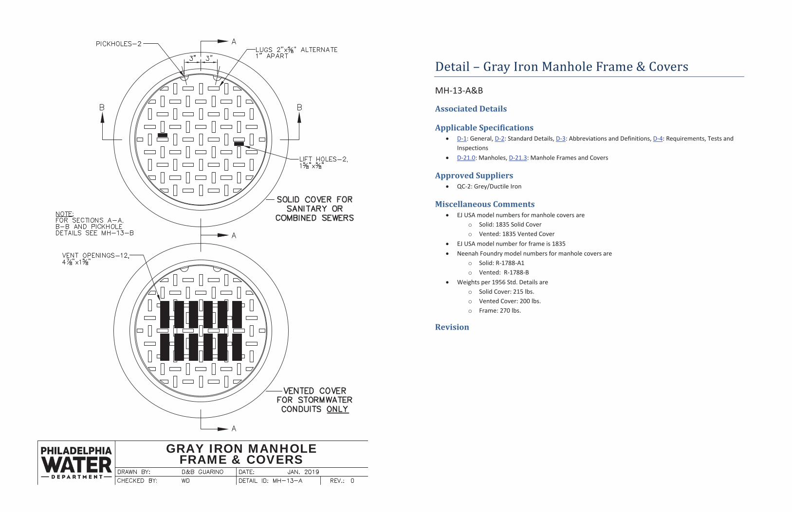
Detail – Gray Iron Manhole Frame & Covers
MH-13-A&B
Associated Details
Applicable Specifications D-1: General, D-2: Standard Details, D-3: Abbreviations and Definitions, D-4: Requirements, Tests and Inspections D-21.0: Manholes, D-21.3: Manhole Frames and Covers
Approved Suppliers QC-2: Grey/Ductile Iron
Miscellaneous Comments EJ USA model numbers for manhole covers are
o Solid: 1835 Solid Cover o Vented: 1835 Vented Cover
EJ USA model number for frame is 1835 Neenah Foundry model numbers for manhole covers are
o Solid: R-1788-A1 o Vented: R-1788-B
Weights per 1956 Std. Details are o Solid Cover: 215 lbs. o Vented Cover: 200 lbs. o Frame: 270 lbs.
Revision
GRAY IRON MANHOLEFRAME & COVERS
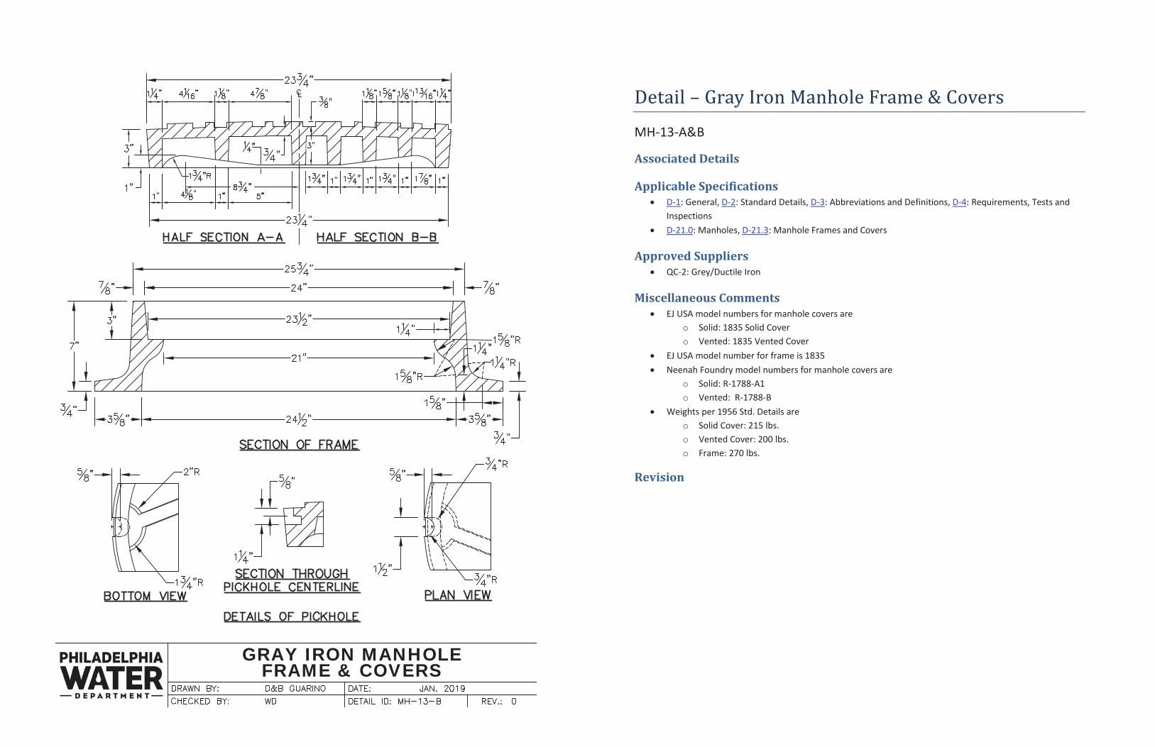
Detail – Gray Iron Manhole Frame & Covers
MH-13-A&B
Associated Details
Applicable Specifications D-1: General, D-2: Standard Details, D-3: Abbreviations and Definitions, D-4: Requirements, Tests and Inspections D-21.0: Manholes, D-21.3: Manhole Frames and Covers
Approved Suppliers QC-2: Grey/Ductile Iron
Miscellaneous Comments EJ USA model numbers for manhole covers are
o Solid: 1835 Solid Cover o Vented: 1835 Vented Cover
EJ USA model number for frame is 1835 Neenah Foundry model numbers for manhole covers are
o Solid: R-1788-A1 o Vented: R-1788-B
Weights per 1956 Std. Details are o Solid Cover: 215 lbs. o Vented Cover: 200 lbs. o Frame: 270 lbs.
Revision
MANHOLE STEPS
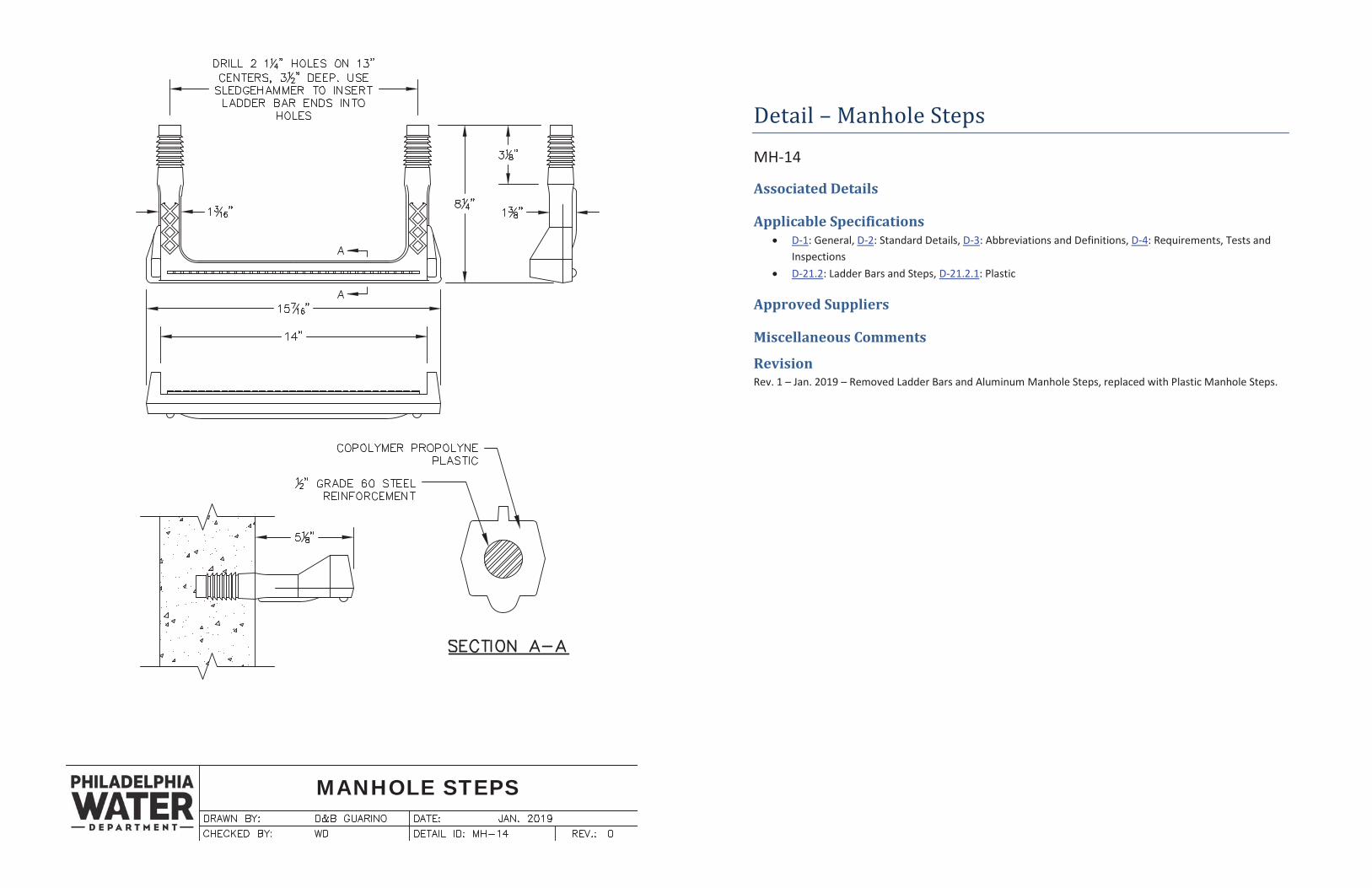
Detail – Manhole Steps
MH-14
Associated Details
Applicable Specifications D-1: General, D-2: Standard Details, D-3: Abbreviations and Definitions, D-4: Requirements, Tests and Inspections D-21.2: Ladder Bars and Steps, D-21.2.1: Plastic
Approved Suppliers
Miscellaneous Comments
Revision Rev. 1 – Jan. 2019 – Removed Ladder Bars and Aluminum Manhole Steps, replaced with Plastic Manhole Steps.
ASSEMBLY OF PRECAST INLETS
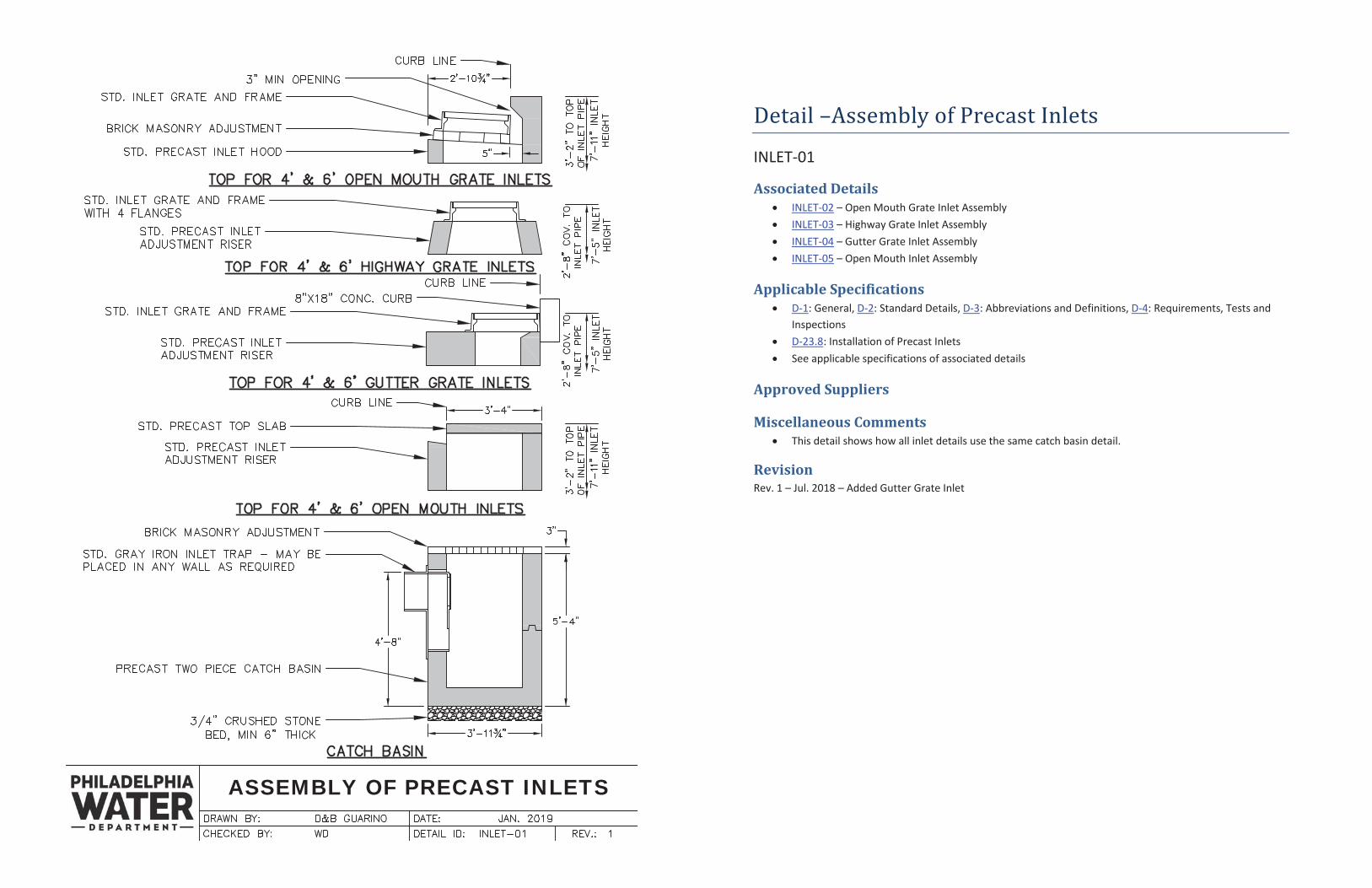
Detail –Assembly of Precast Inlets
INLET-01
Associated Details INLET-02 – Open Mouth Grate Inlet Assembly INLET-03 – Highway Grate Inlet Assembly INLET-04 – Gutter Grate Inlet Assembly INLET-05 – Open Mouth Inlet Assembly
Applicable Specifications D-1: General, D-2: Standard Details, D-3: Abbreviations and Definitions, D-4: Requirements, Tests and Inspections D-23.8: Installation of Precast Inlets See applicable specifications of associated details
Approved Suppliers
Miscellaneous Comments This detail shows how all inlet details use the same catch basin detail.
Revision Rev. 1 – Jul. 2018 – Added Gutter Grate Inlet
OPEN MOUTH GRATE INLETASSEMBLY
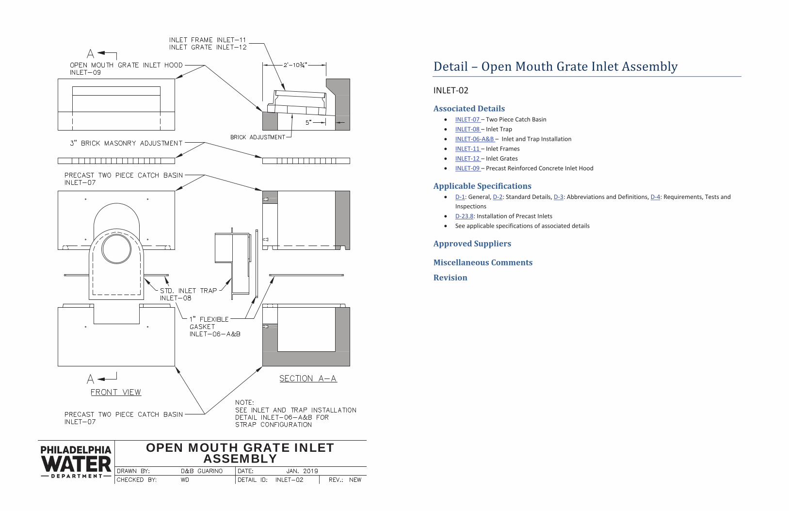
Detail – Open Mouth Grate Inlet Assembly
INLET-02
Associated Details INLET-07 – Two Piece Catch Basin INLET-08 – Inlet Trap INLET-06-A&B – Inlet and Trap Installation INLET-11 – Inlet Frames INLET-12 – Inlet Grates INLET-09 – Precast Reinforced Concrete Inlet Hood
Applicable Specifications D-1: General, D-2: Standard Details, D-3: Abbreviations and Definitions, D-4: Requirements, Tests and Inspections D-23.8: Installation of Precast Inlets See applicable specifications of associated details
Approved Suppliers
Miscellaneous Comments
Revision
HIGHWAY GRATE INLET ASSEMBLY
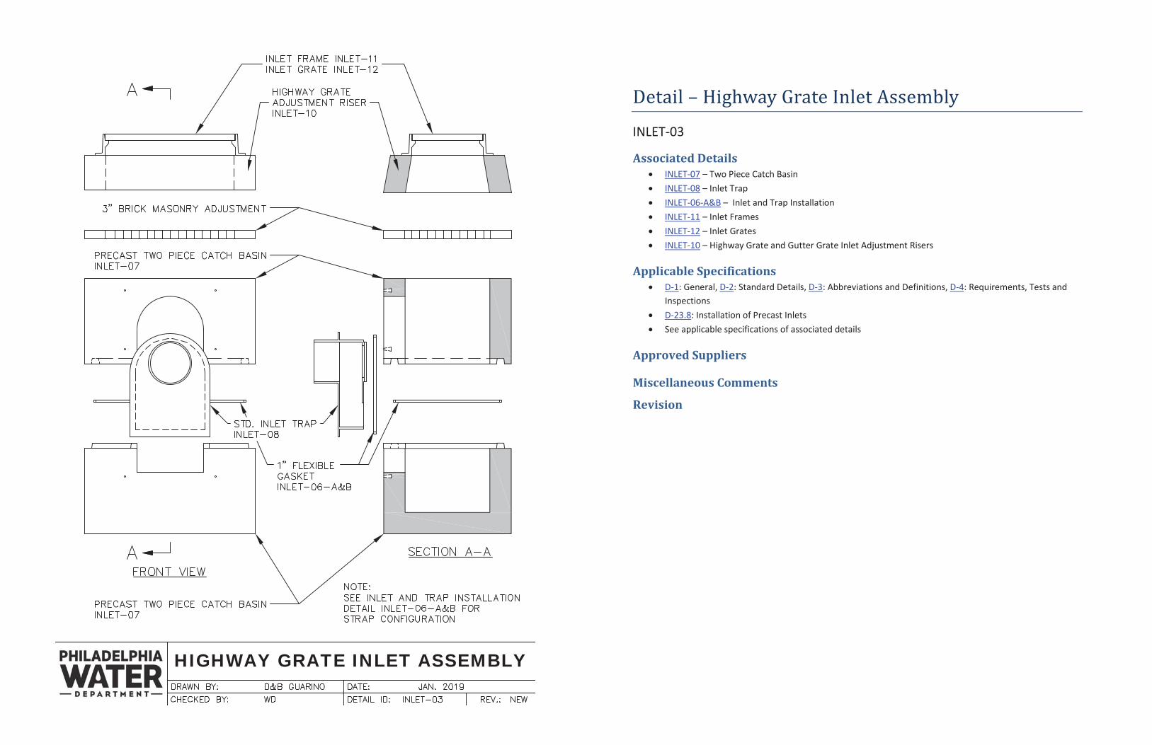
Detail – Highway Grate Inlet Assembly
INLET-03
Associated Details INLET-07 – Two Piece Catch Basin INLET-08 – Inlet Trap INLET-06-A&B – Inlet and Trap Installation INLET-11 – Inlet Frames INLET-12 – Inlet Grates INLET-10 – Highway Grate and Gutter Grate Inlet Adjustment Risers
Applicable Specifications D-1: General, D-2: Standard Details, D-3: Abbreviations and Definitions, D-4: Requirements, Tests and Inspections D-23.8: Installation of Precast Inlets See applicable specifications of associated details
Approved Suppliers
Miscellaneous Comments
Revision
GUTTER GRATE INLET ASSEMBLY
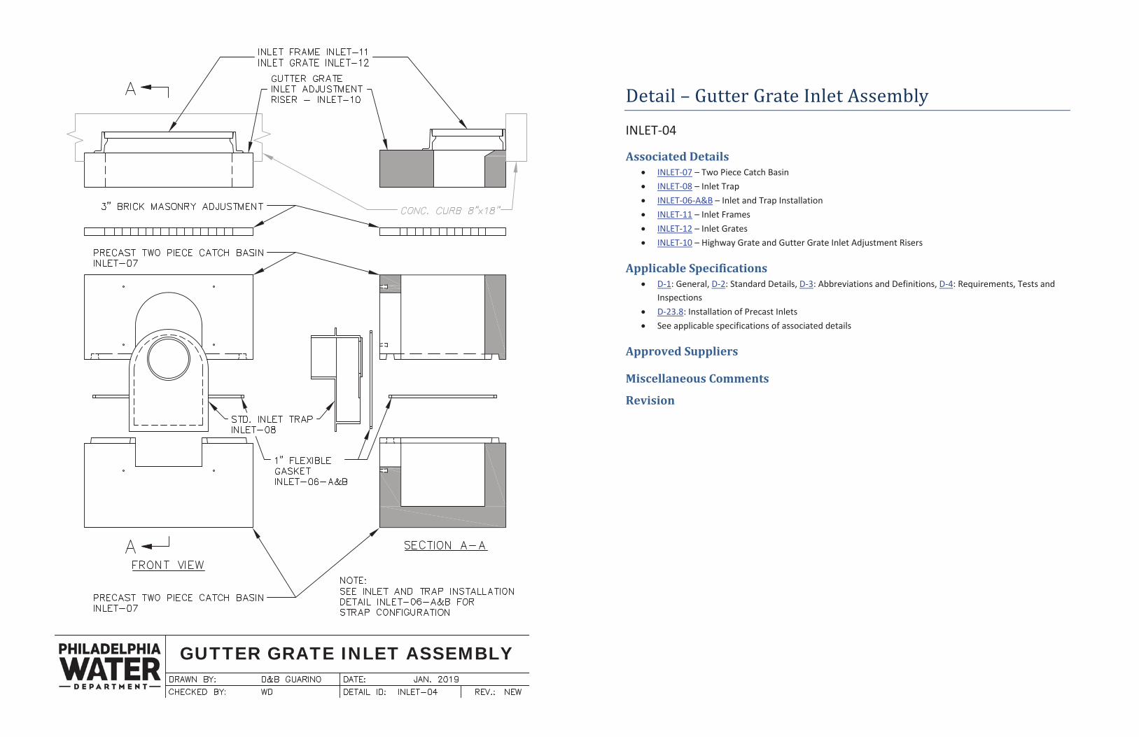
Detail – Gutter Grate Inlet Assembly
INLET-04
Associated Details INLET-07 – Two Piece Catch Basin INLET-08 – Inlet Trap INLET-06-A&B – Inlet and Trap Installation INLET-11 – Inlet Frames INLET-12 – Inlet Grates INLET-10 – Highway Grate and Gutter Grate Inlet Adjustment Risers
Applicable Specifications D-1: General, D-2: Standard Details, D-3: Abbreviations and Definitions, D-4: Requirements, Tests and Inspections D-23.8: Installation of Precast Inlets See applicable specifications of associated details
Approved Suppliers
Miscellaneous Comments
Revision
OPEN MOUTH INLET ASSEMBLY
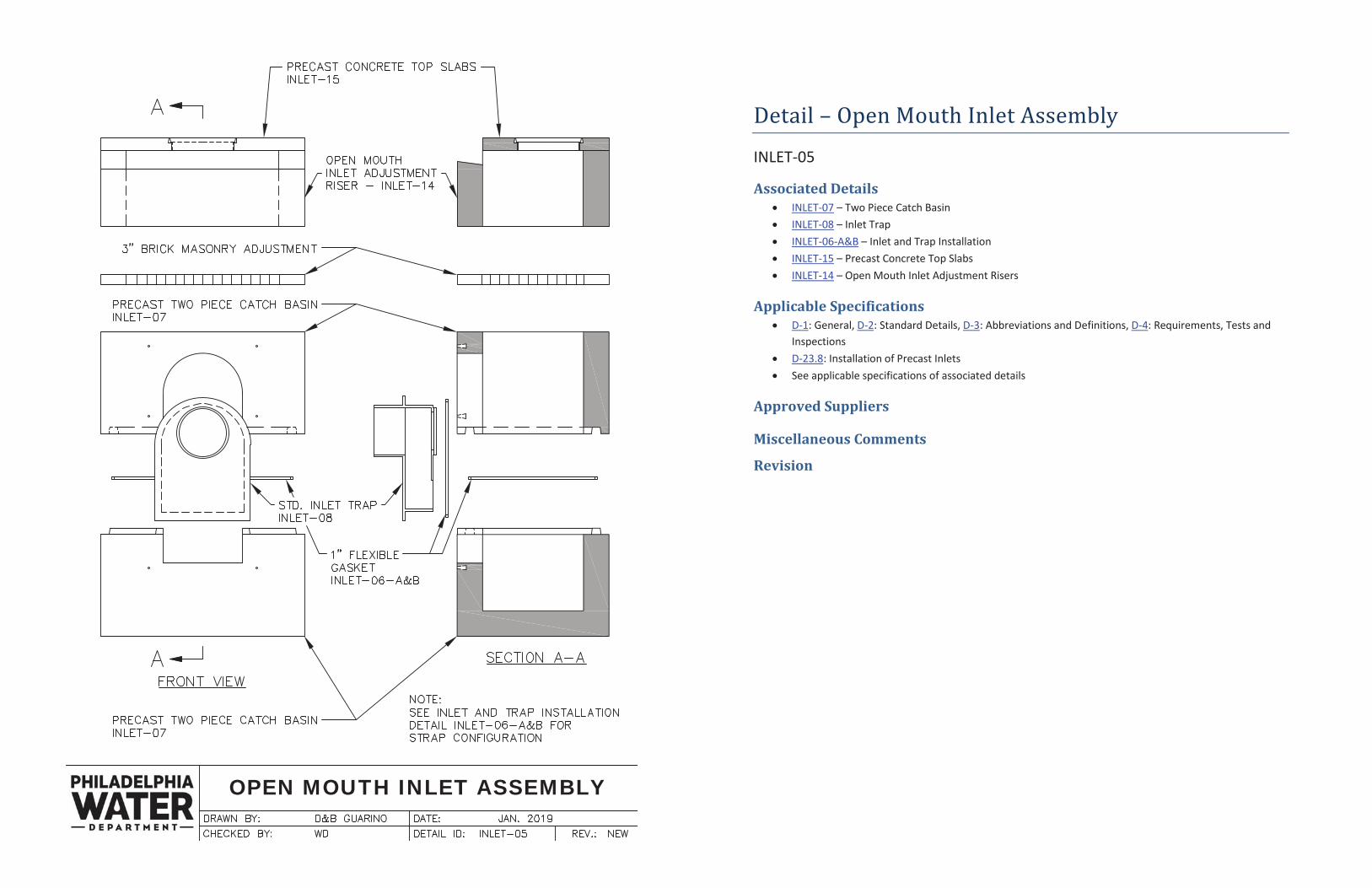
Detail – Open Mouth Inlet Assembly
INLET-05
Associated Details INLET-07 – Two Piece Catch Basin INLET-08 – Inlet Trap INLET-06-A&B – Inlet and Trap Installation INLET-15 – Precast Concrete Top Slabs INLET-14 – Open Mouth Inlet Adjustment Risers
Applicable Specifications D-1: General, D-2: Standard Details, D-3: Abbreviations and Definitions, D-4: Requirements, Tests and Inspections D-23.8: Installation of Precast Inlets See applicable specifications of associated details
Approved Suppliers
Miscellaneous Comments
Revision
INLET & TRAP INSTALLATION
®
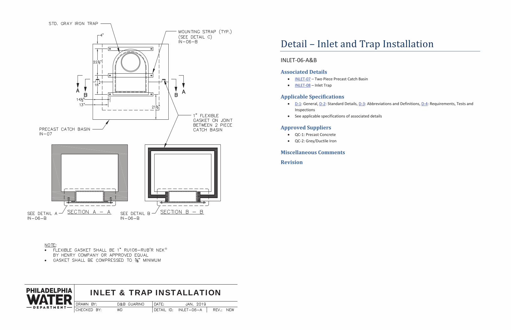
Detail – Inlet and Trap Installation INLET-06-A&B
Associated Details INLET-07 – Two Piece Precast Catch Basin INLET-08 – Inlet Trap
Applicable Specifications D-1: General, D-2: Standard Details, D-3: Abbreviations and Definitions, D-4: Requirements, Tests and Inspections See applicable specifications of associated details
Approved Suppliers QC-1: Precast Concrete QC-2: Grey/Ductile Iron
Miscellaneous Comments
Revision
INLET & TRAP INSTALLATION
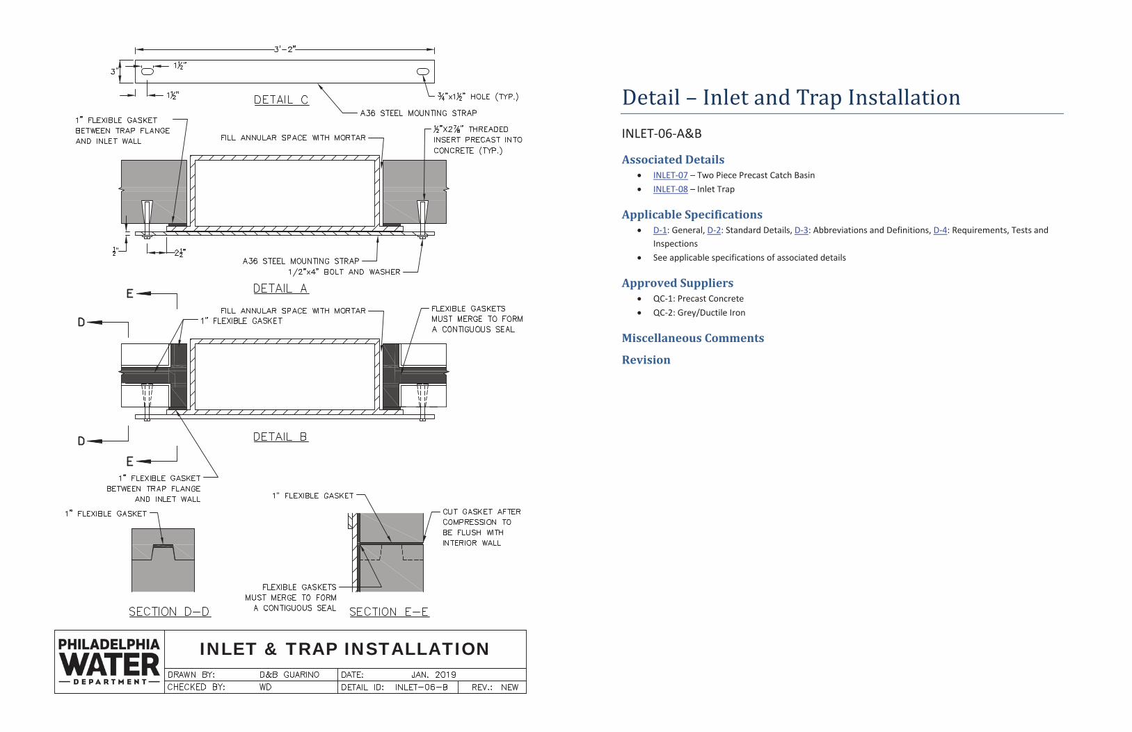
Detail – Inlet and Trap Installation INLET-06-A&B
Associated Details INLET-07 – Two Piece Precast Catch Basin INLET-08 – Inlet Trap
Applicable Specifications D-1: General, D-2: Standard Details, D-3: Abbreviations and Definitions, D-4: Requirements, Tests and Inspections See applicable specifications of associated details
Approved Suppliers QC-1: Precast Concrete QC-2: Grey/Ductile Iron
Miscellaneous Comments
Revision
TWO PIECE PRECAST CATCH BASIN
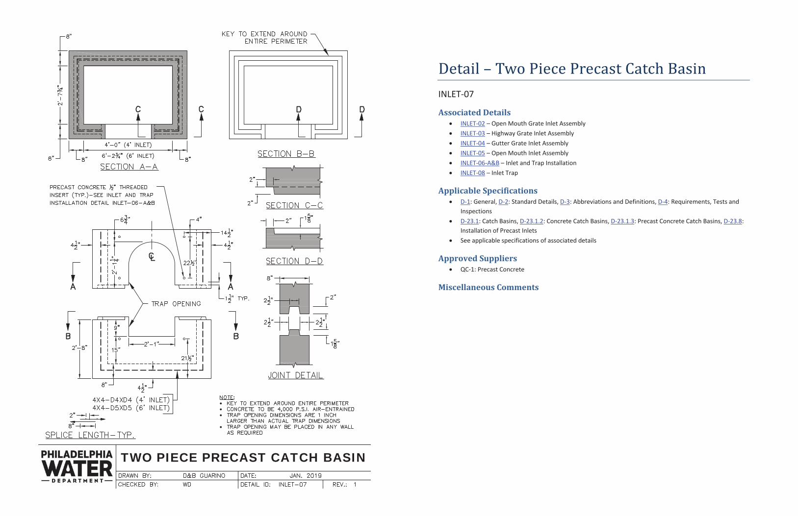
Detail – Two Piece Precast Catch Basin INLET-07
Associated Details INLET-02 – Open Mouth Grate Inlet Assembly INLET-03 – Highway Grate Inlet Assembly INLET-04 – Gutter Grate Inlet Assembly INLET-05 – Open Mouth Inlet Assembly INLET-06-A&B – Inlet and Trap Installation INLET-08 – Inlet Trap
Applicable Specifications D-1: General, D-2: Standard Details, D-3: Abbreviations and Definitions, D-4: Requirements, Tests and Inspections D-23.1: Catch Basins, D-23.1.2: Concrete Catch Basins, D-23.1.3: Precast Concrete Catch Basins, D-23.8: Installation of Precast Inlets See applicable specifications of associated details
Approved Suppliers QC-1: Precast Concrete
Miscellaneous Comments
INLET TRAP
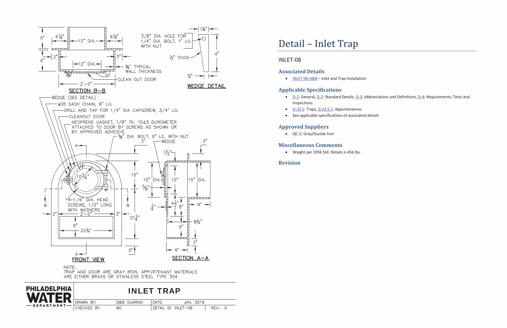
Detail – Inlet Trap INLET-08
Associated Details INLET-06-A&B – Inlet and Trap Installation
Applicable Specifications D-1: General, D-2: Standard Details, D-3: Abbreviations and Definitions, D-4: Requirements, Tests and Inspections D-23.5: Traps, D-23.5.1: Appurtenances See applicable specifications of associated details
Approved Suppliers QC-2: Grey/Ductile Iron
Miscellaneous Comments Weight per 1956 Std. Details is 456 lbs.
Revision
PRECAST CONCRETE INLET HOOD
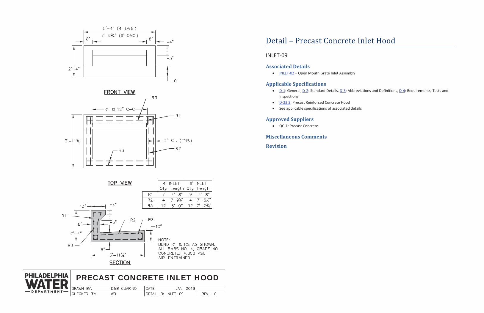
Detail – Precast Concrete Inlet Hood
INLET-09
Associated Details INLET-02 – Open Mouth Grate Inlet Assembly
Applicable Specifications D-1: General, D-2: Standard Details, D-3: Abbreviations and Definitions, D-4: Requirements, Tests and Inspections D-23.2: Precast Reinforced Concrete Hood See applicable specifications of associated details
Approved Suppliers QC-1: Precast Concrete
Miscellaneous Comments
Revision
HIGHWAY GRATE AND GUTTERGRATE INLET ADJUSTMENT RISERS
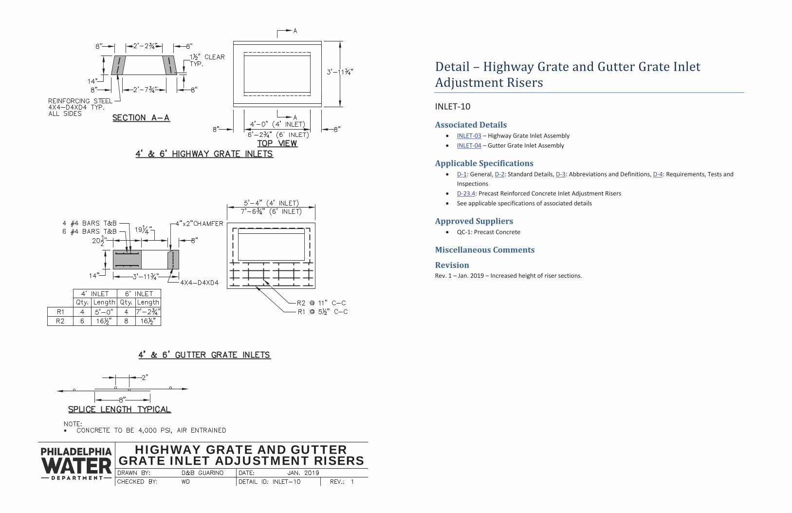
Detail – Highway Grate and Gutter Grate Inlet Adjustment Risers
INLET-10
Associated Details INLET-03 – Highway Grate Inlet Assembly INLET-04 – Gutter Grate Inlet Assembly
Applicable Specifications D-1: General, D-2: Standard Details, D-3: Abbreviations and Definitions, D-4: Requirements, Tests and Inspections D-23.4: Precast Reinforced Concrete Inlet Adjustment Risers See applicable specifications of associated details
Approved Suppliers QC-1: Precast Concrete
Miscellaneous Comments
Revision Rev. 1 – Jan. 2019 – Increased height of riser sections.
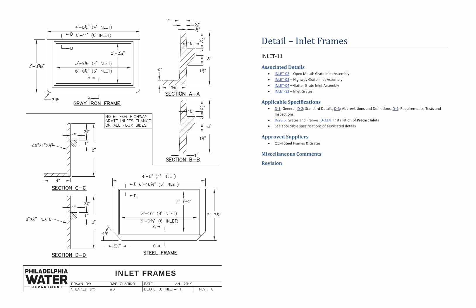
INLET FRAMES
Detail – Inlet Frames INLET-11
Associated Details INLET-02 – Open Mouth Grate Inlet Assembly INLET-03 – Highway Grate Inlet Assembly INLET-04 – Gutter Grate Inlet Assembly INLET-12 – Inlet Grates
Applicable Specifications D-1: General, D-2: Standard Details, D-3: Abbreviations and Definitions, D-4: Requirements, Tests and Inspections D-23.6: Grates and Frames, D-23.8: Installation of Precast Inlets See applicable specifications of associated details
Approved Suppliers QC-4 Steel Frames & Grates
Miscellaneous Comments
Revision
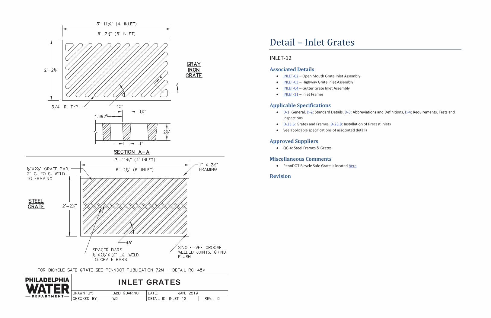
INLET GRATES
Detail – Inlet Grates INLET-12
Associated Details INLET-02 – Open Mouth Grate Inlet Assembly INLET-03 – Highway Grate Inlet Assembly INLET-04 – Gutter Grate Inlet Assembly INLET-11 – Inlet Frames
Applicable Specifications D-1: General, D-2: Standard Details, D-3: Abbreviations and Definitions, D-4: Requirements, Tests and Inspections D-23.6: Grates and Frames, D-23.8: Installation of Precast Inlets See applicable specifications of associated details
Approved Suppliers QC-4: Steel Frames & Grates
Miscellaneous Comments PennDOT Bicycle Safe Grate is located here.
Revision
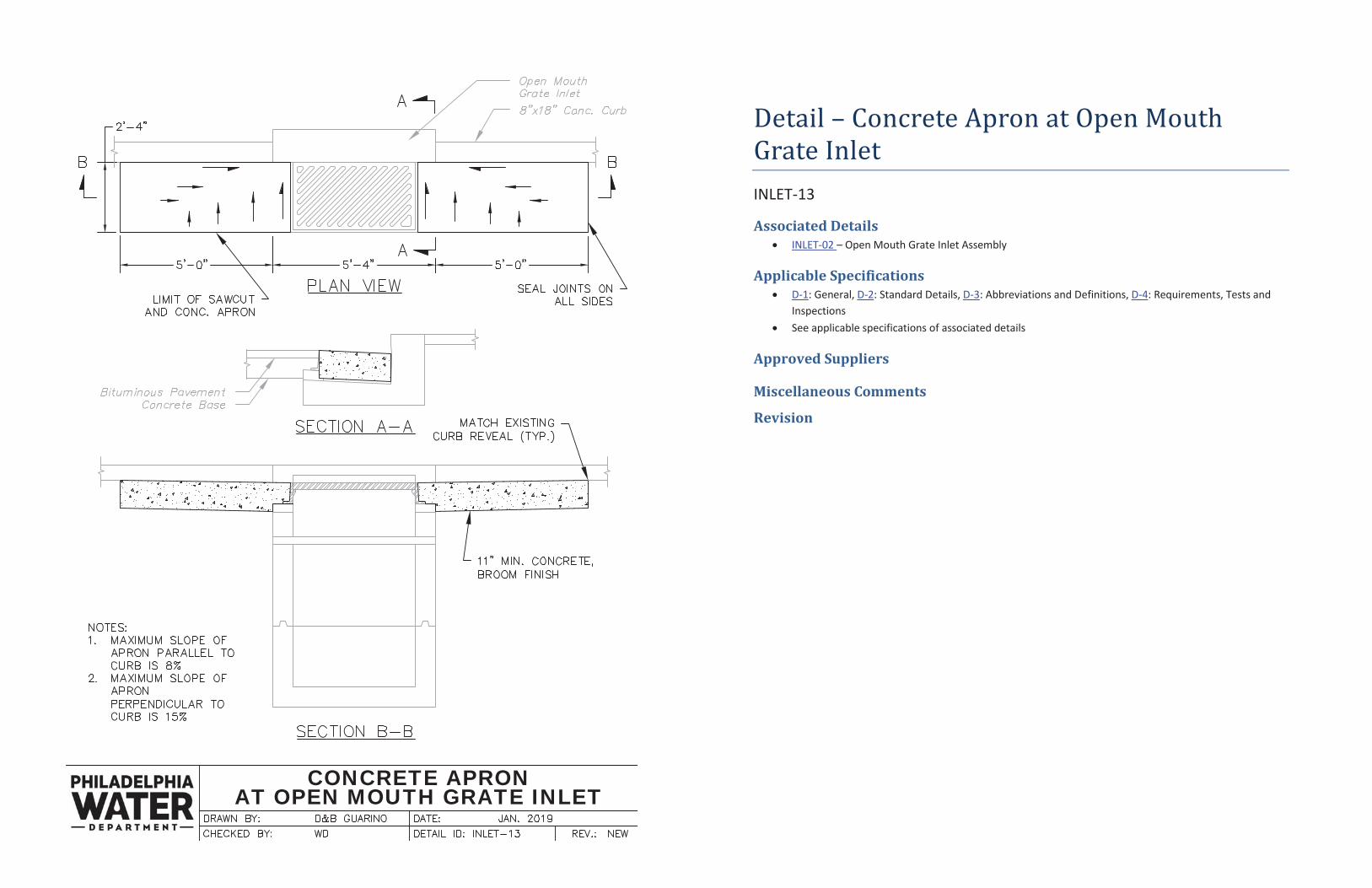
CONCRETE APRONAT OPEN MOUTH GRATE INLET
Detail – Concrete Apron at Open Mouth Grate Inlet INLET-13
Associated Details INLET-02 – Open Mouth Grate Inlet Assembly
Applicable Specifications D-1: General, D-2: Standard Details, D-3: Abbreviations and Definitions, D-4: Requirements, Tests and Inspections See applicable specifications of associated details
Approved Suppliers
Miscellaneous Comments
Revision
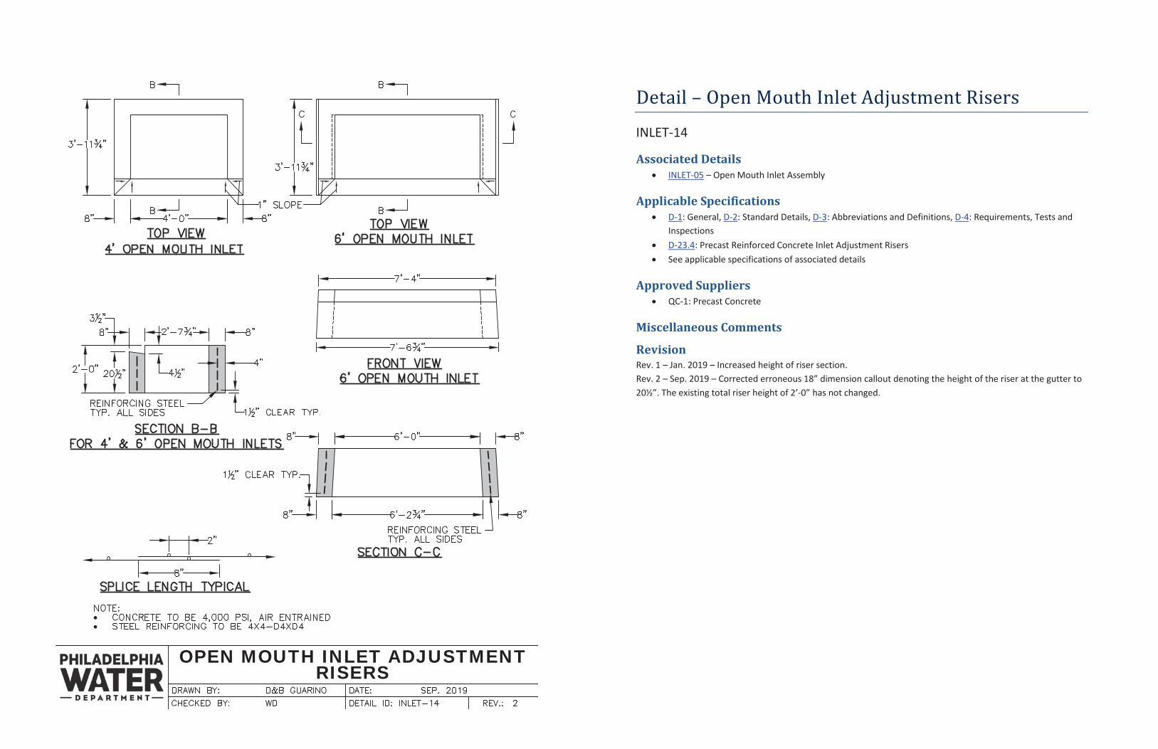
OPEN MOUTH INLET ADJUSTMENTRISERS
Detail – Open Mouth Inlet Adjustment Risers
INLET-14
Associated Details INLET-05 – Open Mouth Inlet Assembly
Applicable Specifications D-1: General, D-2: Standard Details, D-3: Abbreviations and Definitions, D-4: Requirements, Tests and Inspections D-23.4: Precast Reinforced Concrete Inlet Adjustment Risers See applicable specifications of associated details
Approved Suppliers QC-1: Precast Concrete
Miscellaneous Comments
Revision Rev. 1 – Jan. 2019 – Increased height of riser section. Rev. 2 – Sep. 2019 – Corrected erroneous 18” dimension callout denoting the height of the riser at the gutter to 20½”. The existing total riser height of 2’-0” has not changed.
PRECAST CONCRETE TOP SLABS
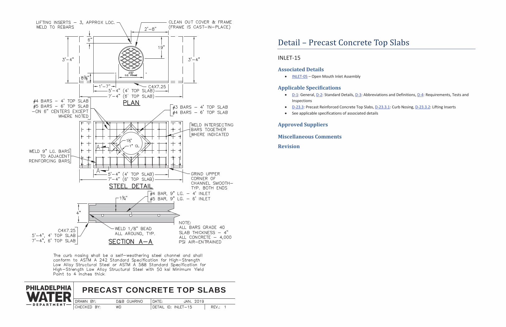
Detail – Precast Concrete Top Slabs
INLET-15
Associated Details INLET-05 – Open Mouth Inlet Assembly
Applicable Specifications D-1: General, D-2: Standard Details, D-3: Abbreviations and Definitions, D-4: Requirements, Tests and Inspections D-23.3: Precast Reinforced Concrete Top Slabs, D-23.3.1: Curb Nosing, D-23.3.2: Lifting Inserts See applicable specifications of associated details
Approved Suppliers
Miscellaneous Comments
Revision
TOP SLAB CLEAN OUT COVER ANDFRAME
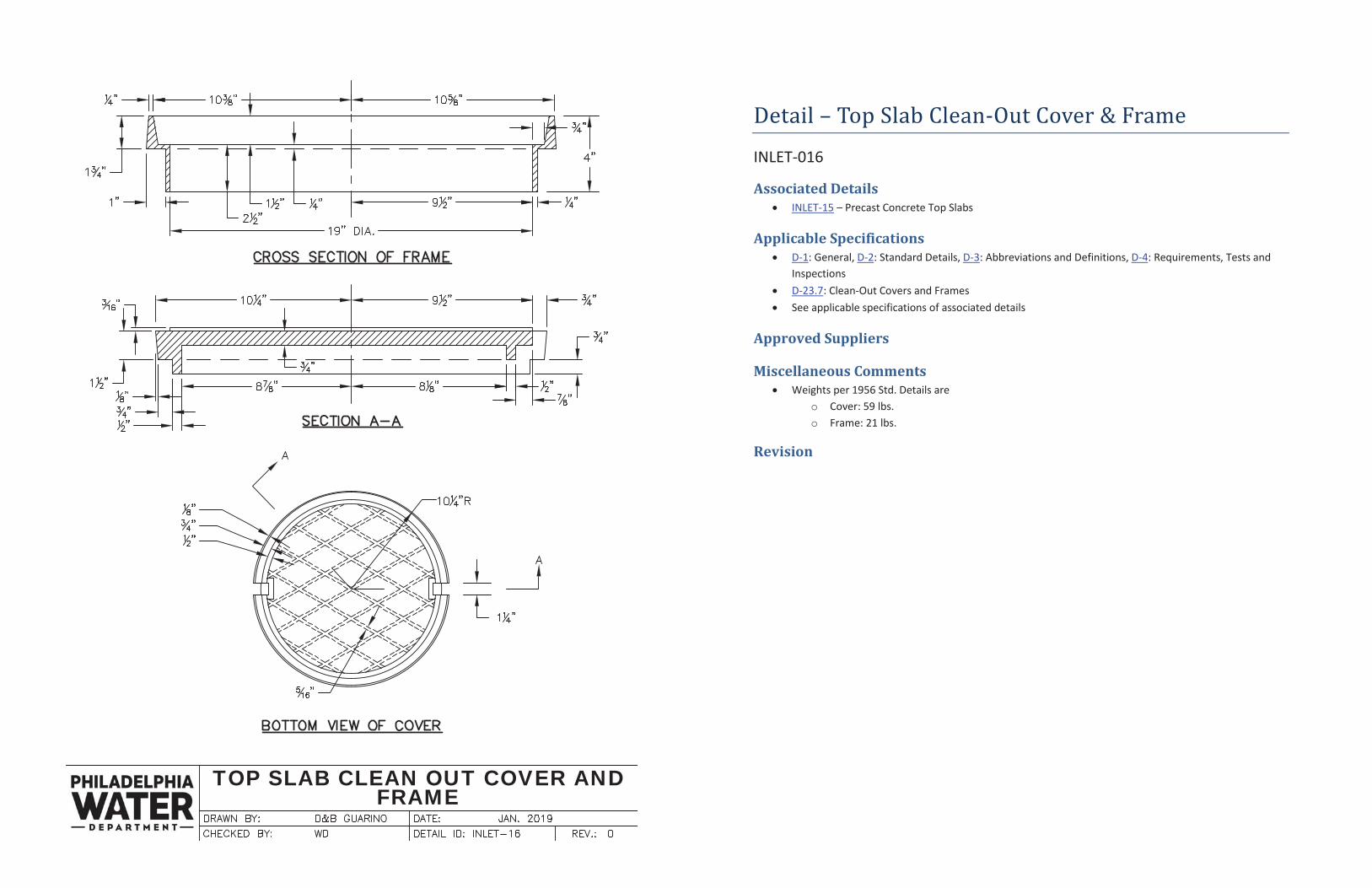
Detail – Top Slab Clean-Out Cover & Frame
INLET-016
Associated Details INLET-15 – Precast Concrete Top Slabs
Applicable Specifications D-1: General, D-2: Standard Details, D-3: Abbreviations and Definitions, D-4: Requirements, Tests and Inspections D-23.7: Clean-Out Covers and Frames See applicable specifications of associated details
Approved Suppliers
Miscellaneous Comments Weights per 1956 Std. Details are
o Cover: 59 lbs. o Frame: 21 lbs.
Revision
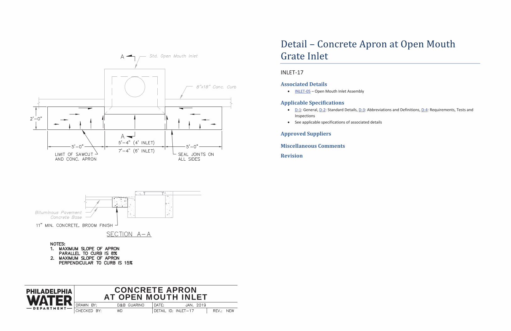
CONCRETE APRONAT OPEN MOUTH INLET
Detail – Concrete Apron at Open Mouth Grate Inlet INLET-17
Associated Details INLET-05 – Open Mouth Inlet Assembly
Applicable Specifications D-1: General, D-2: Standard Details, D-3: Abbreviations and Definitions, D-4: Requirements, Tests and Inspections See applicable specifications of associated details
Approved Suppliers
Miscellaneous Comments
Revision
S-1
D-1 GENERAL These specifications shall apply to all sewers and/or stormwater conduits that are constructed for the City of Philadelphia or that are paid for by private cost and inspected by the Water Department. All sewers and/or stormwater conduits that will or that may eventually be maintained by the City must be inspected by the Water Department. D-2 STANDARD DETAILS The Philadelphia Water Department’s Standard Details for Sewers shall apply to sewers and/or stormwater conduits constructed under these specifications, except where the Standard Details are modified by the Plans or Specified Specifications of work, whereupon the Contractor will be required to construct the section, as modified in the Plans or Specifications, at the prices bid in the Proposal. D-3 ABBREVIATIONS AND DEFINITIONS
The following abbreviations have been used throughout these specifications: ACI - American Concrete Institute AISC - American Institute of Steel Construction ANSI - American National Standards Institute ASTM - ASTM International (formerly American Society for Testing and Materials) AWS - American Welding Society AWWA - American Water Works Association CRD - Capstone Requirements Document (Army Corps of Engineers) DIPRA - Ductile Iron Pipe Research Association FTMS - Federal Test Method Standard PWD - Philadelphia Water Department QCS - (PWD) Quality Control Standard
The following definitions have been used throughout these specifications: City - City of Philadelphia Engineer - General Manager of Planning and Engineering of the Water Department or his duly authorized representative Inspector - A representative of the Engineer responsible for inspection Construction - New construction and reconstruction Sanitary Sewer - A sewer that carries sewage only Combined Sewer - A sewer that carries sewage and stormwater Stormwater Conduit - A conduit that carries stormwater only Separate System - A collection system that consists of a separate stormwater conduit and a sanitary sewer. Interceptor or Intercepting Sewer - A main branch of the collection system that leads directly to another interceptor or a water pollution control plant. Standard Details for Sewers - The Philadelphia Water Department’s Standard details that are included with this publication.
S-2
D-4 REQUIREMENTS, TESTS AND INSPECTIONS All materials used in Water Department contracts for the construction of sewers and
stormwater conduits shall conform to the requirements as noted in the Standard Details for Sewers, and these specifications, except where noted on the Plans or revised in the Contract Specifications.
Materials shall be obtained from suppliers on the “Lists of Approved Suppliers of Materials for Water Department Contracts”. The Contractor shall submit to the Engineer his/her list of suppliers for the Contract.
All materials shall be tested for conformance to the current specifications, and in accordance with the current standard test methods, of technical societies, institutes, associations or Federal and State specifications, as called for in these specifications, in the Contract Specifications or as called for the by the Engineer. Current specifications and current standard test methods are defined as the latest editions, amendments or revisions that are current at the time of the receipt of bids. The Contractor shall transport, without charge, the test specimens to the Materials Testing Laboratory of the Water Department.
Construction of sewers, stormwater conduits and appurtenances shall be inspected by the Water Department. Final inspection may be made by use of a closed circuit television system. The Contractor will be required to assist the Inspector in making this inspection. See City Standard Contract Requirement for additional information regarding inspection.
All work shall be done in accordance with the Standard Details and Standard Specifications for Sewers except if directed by the engineer.
D-5 LINES AND GRADES
All pipes and reinforced concrete sections shall be laid in an upstream direction to the line and grades furnished by the Engineer. All pipes shall be laid with the bell end upgrade. All pipes and reinforced concrete sections, when laid together, shall make a continuous and uniform line with a smooth, regular interior surface.
D-6 WIDTH OF TRENCHES
The width of the trenches for sewers shall be the outside edge of the cradle as detailed in the current Standard Details for Sewers or as shown on the plans. The width of the trenches for pipe(s) not in concrete cradle shall be as shown on Typical Street Section (PIPE-04) or as shown on the plans.
D-7 INSTALLATION OF PIPES
Care shall be taken in placing the pipe into the trench to prevent damaging the joints or joint-material and to prevent disturbing the trench.
The manufacturer’s recommendations for pipe assembly must be closely followed. Care must be taken to clean the mating surfaces of the joints before jointing. The jointing surfaces shall be lubricated as recommended by the manufacturer. The pipe ends shall be aligned and assembled by hand, bar or the use of come-along. In all instances the ends of the pipe must be protected against damage.
S-3
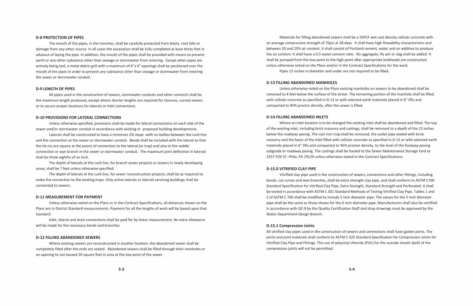
D-8 PROTECTION OF PIPES The mouth of the pipes, in the trenches, shall be carefully protected from blasts, rock falls or
damage from any other source. In all cases the excavation shall be fully completed at least thirty feet in advance of laying the pipe. In addition, the mouth of the pipes shall be provided with means to prevent earth or any other substance other than sewage or stormwater from entering. Except when pipes are actively being laid, a metal debris grill with a maximum of 6”x 6” openings shall be positioned over the mouth of the pipes in order to prevent any substance other than sewage or stormwater from entering the sewer or stormwater conduit.
D-9 LENGTH OF PIPES
All pipes used in the construction of sewers, stormwater conduits and other connects shall be the maximum length produced, except where shorter lengths are required for closures, curved sewers or to secure proper locations for laterals or inlet connections. D-10 PROVISIONS FOR LATERAL CONNECTIONS
Unless otherwise specified, provisions shall be made for lateral connections on each side of the sewer and/or stormwater conduit in accordance with existing or proposed building developments.
Laterals shall be constructed to have a minimum 2% slope -with no bellies between the curb line and the connection at the sewer or stormwater conduit. Bends shall be included with the lateral so that the tie-ins are square at the points of connection to the lateral (or trap) and also to the saddle connection or wye branch in the sewer or stormwater conduit. The maximum joint deflection in laterals shall be three eighths of an inch.
The depth of laterals at the curb line, for branch sewer projects or sewers in newly developing areas, shall be 7 feet unless otherwise specified.
The depth of laterals at the curb line, for sewer reconstruction projects, shall be as required to make the connection to the existing traps. Only active laterals or laterals servicing buildings shall be connected to sewers.
D-11 MEASUREMENT FOR PAYMENT
Unless otherwise noted on the Plans or in the Contract Specifications, all distances shown on the Plans are in District Standard measurements. Payment for all the lengths of work will be based upon that standard.
Inlet, lateral and drain connections shall be paid for by linear measurement. No extra allowance will be made for the necessary bends and branches. D-12 FILLING ABANDONED SEWERS
Where existing sewers are reconstructed in another location, the abandoned sewer shall be completely filled after the ends are sealed. Abandoned sewers shall be filled through their manholes or an opening to not exceed 20 square feet in area at the low point of the sewer.
S-4
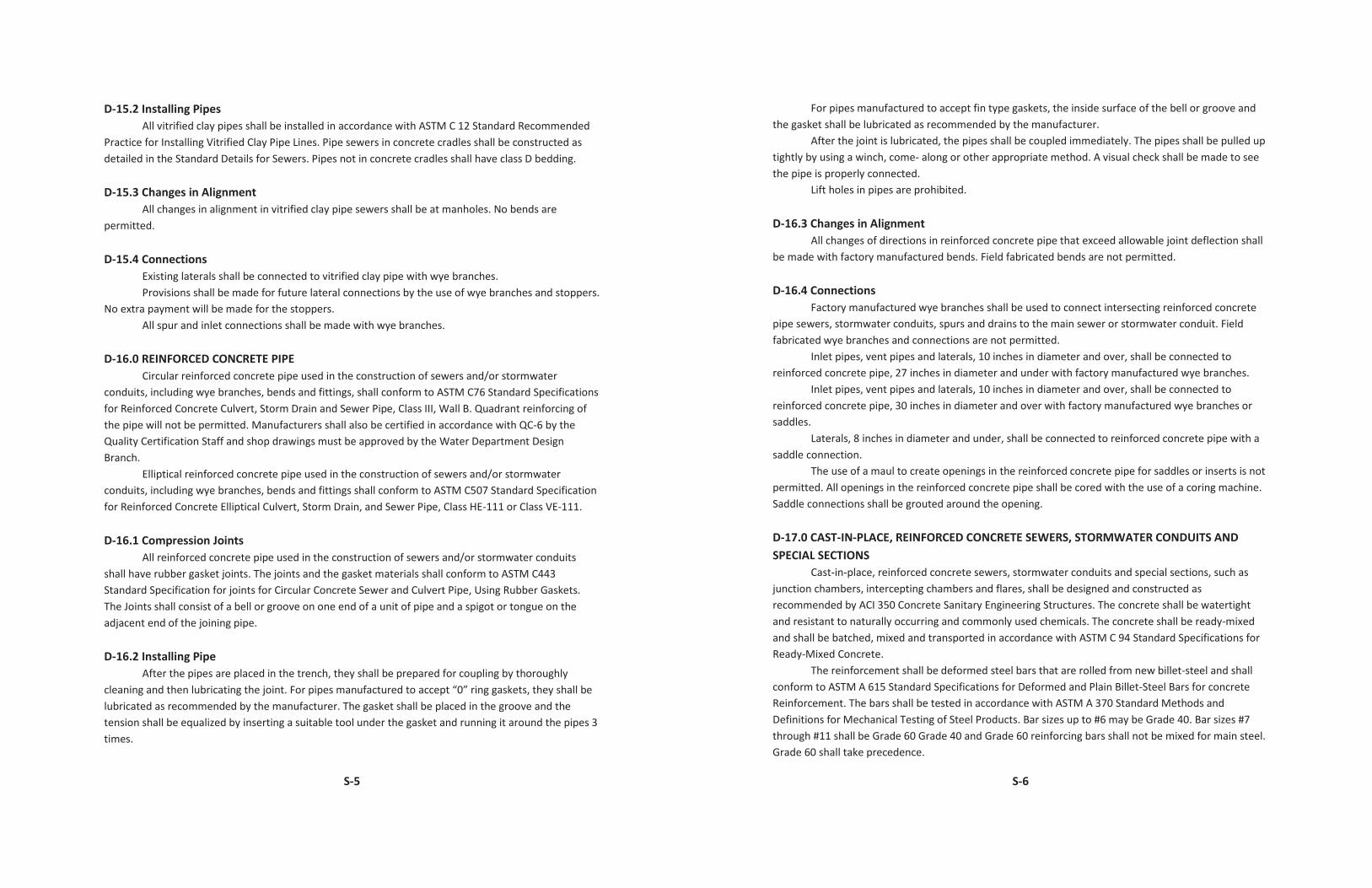
Materials for filling abandoned sewers shall be a 25PCF wet cast density cellular concrete with an average compressive strength of 70psi at 28 days. It shall have high flowability characteristics and between 20 and 25% air content. It shall consist of Portland cement, water and an additive to produce the air content. It shall have a 0.5 water:cement ratio. No aggregate, fly ash or slag shall be added. It shall be pumped from the low point to the high point after appropriate bulkheads are constructed unless otherwise noted on the Plans and/or in the Contract Specifications for the work.
Pipes 15 inches in diameter and under are not required to be filled.
D-13 FILLING ABANDONED MANHOLES Unless otherwise noted on the Plans existing manholes on sewers to be abandoned shall be
removed to 4 feet below the surface of the street. The remaining portion of the manhole shall be filled with cellular concrete as specified in D-12 or with selected earth materials placed in 6” lifts and compacted to 95% proctor density, after the sewer is filled.
D-14 FILLING ABANDONED INLETS
Where an inlet location is to be changed the existing inlet shall be abandoned and filled. The top of the existing inlet, including brick masonry and castings, shall be removed to a depth of the 12 inches below the roadway paving. The cast iron trap shall be removed, the outlet pipe sealed with brick masonry and the basin of the inlet filled with cellular concrete as specified in D-12 or with selected earth materials placed in 6” lifts and compacted to 95% proctor density, to the level of the footway paving subgrade or roadway paving. The castings shall be hauled to the Sewer Maintenance Storage Yard at 3257 FOX ST. Phila, PA 19129 unless otherwise stated in the Contract Specifications.
D-15.0 VITRIFIED CLAY PIPE
Vitrified clay pipe used in the construction of sewers, connections and other fittings, including bends, cut curves and wye branches, shall be extra strength clay pipe, and shall conform to ASTM C700 Standard Specification for Vitrified Clay Pipe, Extra Strength, Standard Strength and Perforated. It shall be tested in accordance with ASTM C 301 Standard Methods of Testing Vitrified Clay Pipe. Tables 1 and 2 of ASTM C 700 shall be modified to include 5 inch diameter pipe. The values for the 5 inch diameter pipe shall be the same as those shown for the 6 inch diameter pipe. Manufacturers shall also be certified in accordance with QC-9 by the Quality Certification Staff and shop drawings must be approved by the Water Department Design Branch.
D-15.1 Compression Joints All vitrified clay pipes used in the construction of sewers and connections shall have gasket joints. The joints and joint materials shall conform to ASTM C 425 Standard Specification for Compression Joints for Vitrified Clay Pipe and Fittings. The use of polyvinyl chloride (PVC) for the outside sheath (bell) of the compression joints will not be permitted.
S-5
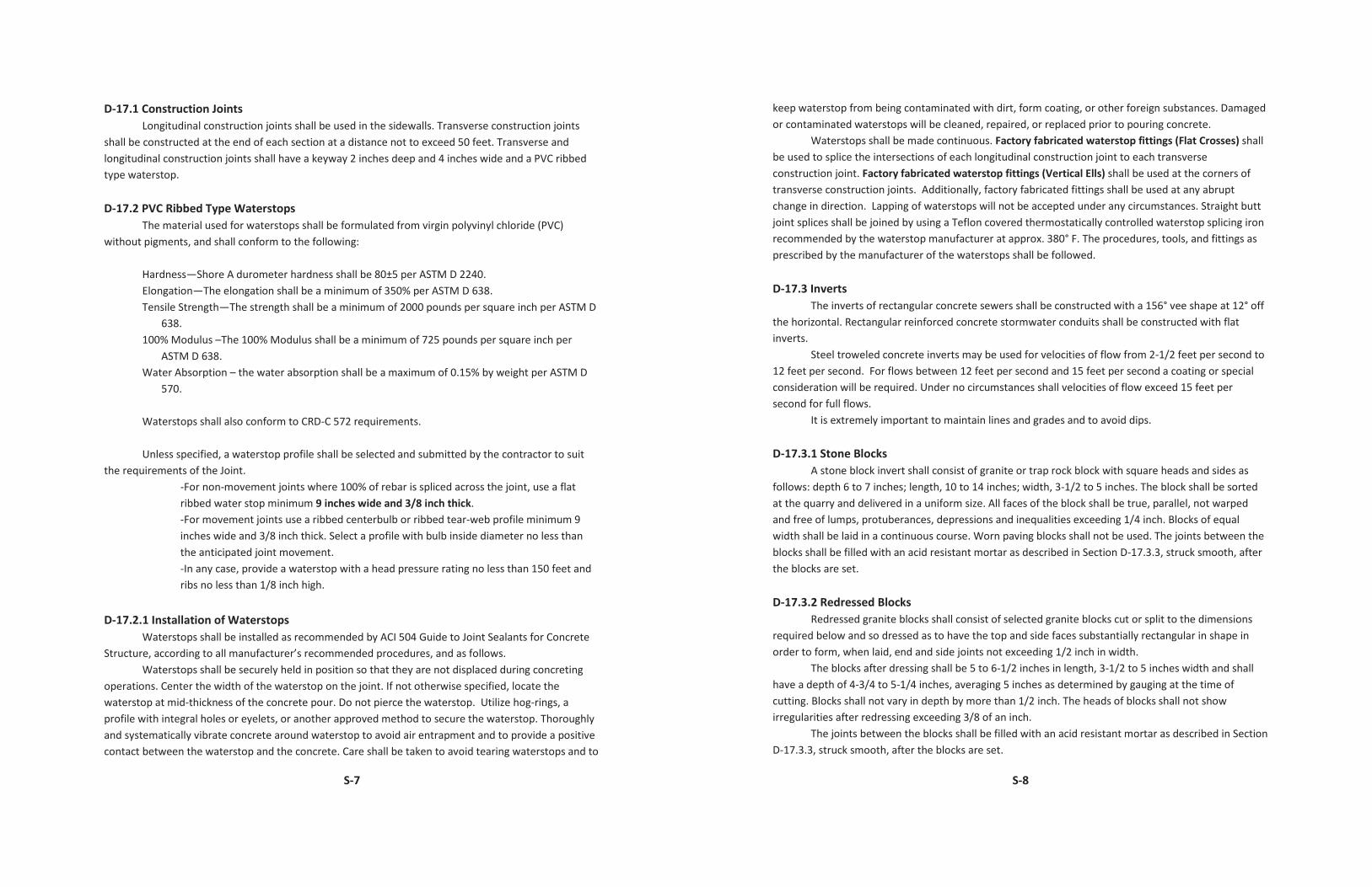
D-15.2 Installing Pipes All vitrified clay pipes shall be installed in accordance with ASTM C 12 Standard Recommended
Practice for Installing Vitrified Clay Pipe Lines. Pipe sewers in concrete cradles shall be constructed as detailed in the Standard Details for Sewers. Pipes not in concrete cradles shall have class D bedding.
D-15.3 Changes in Alignment
All changes in alignment in vitrified clay pipe sewers shall be at manholes. No bends are permitted.
D-15.4 Connections
Existing laterals shall be connected to vitrified clay pipe with wye branches. Provisions shall be made for future lateral connections by the use of wye branches and stoppers.
No extra payment will be made for the stoppers. All spur and inlet connections shall be made with wye branches.
D-16.0 REINFORCED CONCRETE PIPE Circular reinforced concrete pipe used in the construction of sewers and/or stormwater
conduits, including wye branches, bends and fittings, shall conform to ASTM C76 Standard Specifications ant reinforcing of
the pipe will not be permitted. Manufacturers shall also be certified in accordance with QC-6 by the Quality Certification Staff and shop drawings must be approved by the Water Department Design Branch.
Elliptical reinforced concrete pipe used in the construction of sewers and/or stormwater conduits, including wye branches, bends and fittings shall conform to ASTM C507 Standard Specification for Reinforced Concrete Elliptical Culvert, Storm Drain, and Sewer Pipe, Class HE-111 or Class VE-111.
D-16.1 Compression Joints
All reinforced concrete pipe used in the construction of sewers and/or stormwater conduits shall have rubber gasket joints. The joints and the gasket materials shall conform to ASTM C443 Standard Specification for joints for Circular Concrete Sewer and Culvert Pipe, Using Rubber Gaskets. The Joints shall consist of a bell or groove on one end of a unit of pipe and a spigot or tongue on the adjacent end of the joining pipe.
D-16.2 Installing Pipe
After the pipes are placed in the trench, they shall be prepared for coupling by thoroughly cleaning and then lubricating the joint. For pipes manufactured to accept “0” ring gaskets, they shall be lubricated as recommended by the manufacturer. The gasket shall be placed in the groove and the tension shall be equalized by inserting a suitable tool under the gasket and running it around the pipes 3 times.
S-6
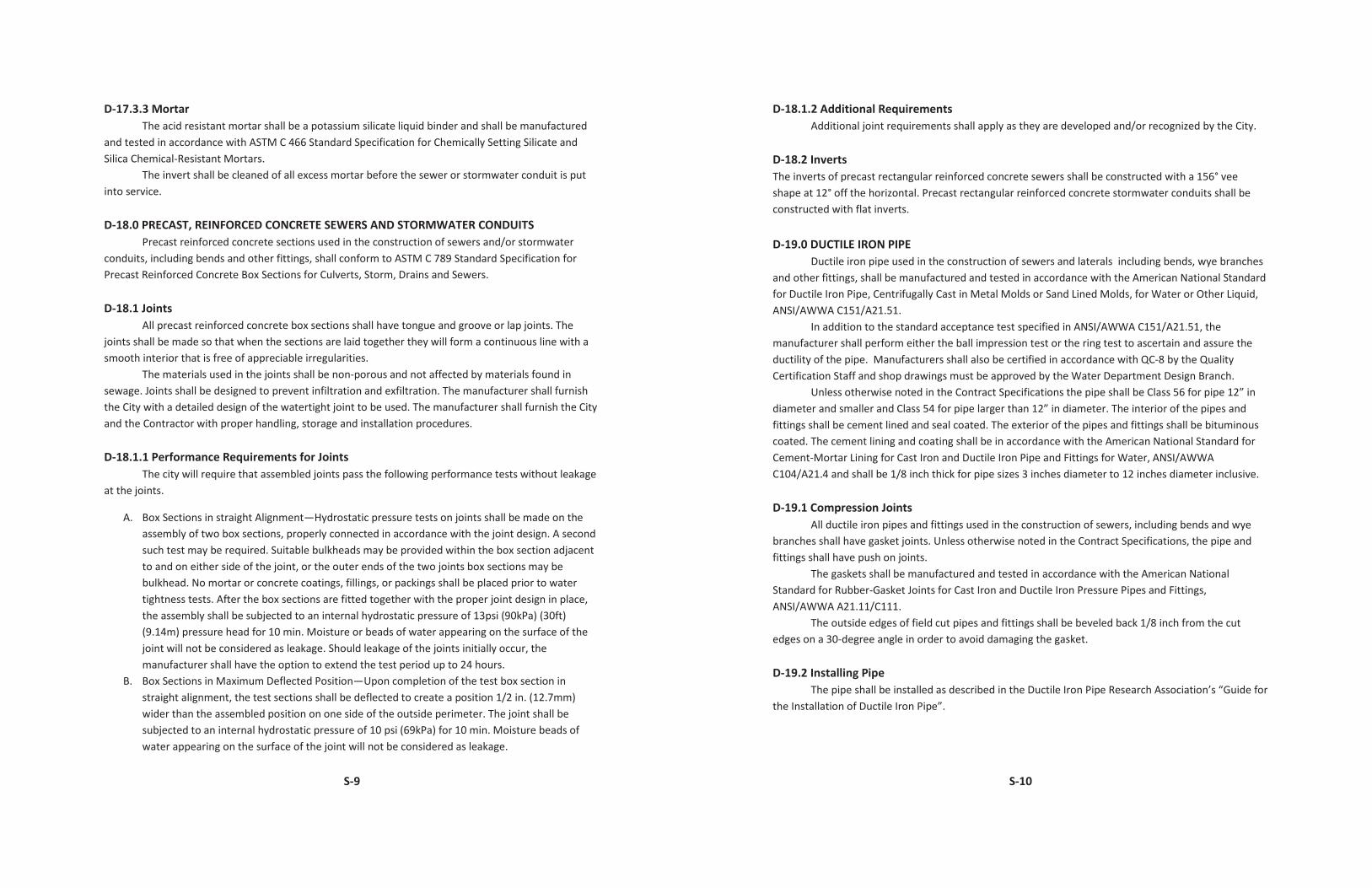
For pipes manufactured to accept fin type gaskets, the inside surface of the bell or groove and the gasket shall be lubricated as recommended by the manufacturer.
After the joint is lubricated, the pipes shall be coupled immediately. The pipes shall be pulled up tightly by using a winch, come- along or other appropriate method. A visual check shall be made to see the pipe is properly connected.
Lift holes in pipes are prohibited.
D-16.3 Changes in Alignment All changes of directions in reinforced concrete pipe that exceed allowable joint deflection shall
be made with factory manufactured bends. Field fabricated bends are not permitted.
D-16.4 Connections Factory manufactured wye branches shall be used to connect intersecting reinforced concrete
pipe sewers, stormwater conduits, spurs and drains to the main sewer or stormwater conduit. Field fabricated wye branches and connections are not permitted.
Inlet pipes, vent pipes and laterals, 10 inches in diameter and over, shall be connected to reinforced concrete pipe, 27 inches in diameter and under with factory manufactured wye branches.
Inlet pipes, vent pipes and laterals, 10 inches in diameter and over, shall be connected to reinforced concrete pipe, 30 inches in diameter and over with factory manufactured wye branches or saddles.
Laterals, 8 inches in diameter and under, shall be connected to reinforced concrete pipe with a saddle connection.
The use of a maul to create openings in the reinforced concrete pipe for saddles or inserts is not permitted. All openings in the reinforced concrete pipe shall be cored with the use of a coring machine. Saddle connections shall be grouted around the opening.
D-17.0 CAST-IN-PLACE, REINFORCED CONCRETE SEWERS, STORMWATER CONDUITS AND SPECIAL SECTIONS
Cast-in-place, reinforced concrete sewers, stormwater conduits and special sections, such as junction chambers, intercepting chambers and flares, shall be designed and constructed as recommended by ACI 350 Concrete Sanitary Engineering Structures. The concrete shall be watertight and resistant to naturally occurring and commonly used chemicals. The concrete shall be ready-mixed and shall be batched, mixed and transported in accordance with ASTM C 94 Standard Specifications for Ready-Mixed Concrete.
The reinforcement shall be deformed steel bars that are rolled from new billet-steel and shall conform to ASTM A 615 Standard Specifications for Deformed and Plain Billet-Steel Bars for concrete Reinforcement. The bars shall be tested in accordance with ASTM A 370 Standard Methods and Definitions for Mechanical Testing of Steel Products. Bar sizes up to #6 may be Grade 40. Bar sizes #7 through #11 shall be Grade 60 Grade 40 and Grade 60 reinforcing bars shall not be mixed for main steel. Grade 60 shall take precedence.
S-7
D-17.1 Construction Joints Longitudinal construction joints shall be used in the sidewalls. Transverse construction joints
shall be constructed at the end of each section at a distance not to exceed 50 feet. Transverse and longitudinal construction joints shall have a keyway 2 inches deep and 4 inches wide and a PVC ribbed type waterstop.
D-17.2 PVC Ribbed Type Waterstops
The material used for waterstops shall be formulated from virgin polyvinyl chloride (PVC) without pigments, and shall conform to the following:
Hardness—Shore A durometer hardness shall be 80±5 per ASTM D 2240. Elongation—The elongation shall be a minimum of 350% per ASTM D 638. Tensile Strength—The strength shall be a minimum of 2000 pounds per square inch per ASTM D
638. 100% Modulus –The 100% Modulus shall be a minimum of 725 pounds per square inch per
ASTM D 638. Water Absorption – the water absorption shall be a maximum of 0.15% by weight per ASTM D
570. Waterstops shall also conform to CRD-C 572 requirements. Unless specified, a waterstop profile shall be selected and submitted by the contractor to suit
the requirements of the Joint. -For non-movement joints where 100% of rebar is spliced across the joint, use a flat
ribbed water stop minimum 9 inches wide and 3/8 inch thick. -For movement joints use a ribbed centerbulb or ribbed tear-web profile minimum 9
inches wide and 3/8 inch thick. Select a profile with bulb inside diameter no less than the anticipated joint movement.
-In any case, provide a waterstop with a head pressure rating no less than 150 feet and ribs no less than 1/8 inch high.
D-17.2.1 Installation of Waterstops
Waterstops shall be installed as recommended by ACI 504 Guide to Joint Sealants for Concrete Structure, according to all manufacturer’s recommended procedures, and as follows.
Waterstops shall be securely held in position so that they are not displaced during concreting operations. Center the width of the waterstop on the joint. If not otherwise specified, locate the waterstop at mid-thickness of the concrete pour. Do not pierce the waterstop. Utilize hog-rings, a profile with integral holes or eyelets, or another approved method to secure the waterstop. Thoroughly and systematically vibrate concrete around waterstop to avoid air entrapment and to provide a positive contact between the waterstop and the concrete. Care shall be taken to avoid tearing waterstops and to
S-8
keep waterstop from being contaminated with dirt, form coating, or other foreign substances. Damaged or contaminated waterstops will be cleaned, repaired, or replaced prior to pouring concrete.
Waterstops shall be made continuous. Factory fabricated waterstop fittings (Flat Crosses) shall be used to splice the intersections of each longitudinal construction joint to each transverse construction joint. Factory fabricated waterstop fittings (Vertical Ells) shall be used at the corners of transverse construction joints. Additionally, factory fabricated fittings shall be used at any abrupt change in direction. Lapping of waterstops will not be accepted under any circumstances. Straight butt joint splices shall be joined by using a Teflon covered thermostatically controlled waterstop splicing iron recommended by the waterstop manufacturer at approx. 380° F. The procedures, tools, and fittings as prescribed by the manufacturer of the waterstops shall be followed.
D-17.3 Inverts
The inverts of rectangular concrete sewers shall be constructed with a 156° vee shape at 12° off the horizontal. Rectangular reinforced concrete stormwater conduits shall be constructed with flat inverts.
Steel troweled concrete inverts may be used for velocities of flow from 2-1/2 feet per second to 12 feet per second. For flows between 12 feet per second and 15 feet per second a coating or special consideration will be required. Under no circumstances shall velocities of flow exceed 15 feet per second for full flows.
It is extremely important to maintain lines and grades and to avoid dips.
D-17.3.1 Stone Blocks A stone block invert shall consist of granite or trap rock block with square heads and sides as
follows: depth 6 to 7 inches; length, 10 to 14 inches; width, 3-1/2 to 5 inches. The block shall be sorted at the quarry and delivered in a uniform size. All faces of the block shall be true, parallel, not warped and free of lumps, protuberances, depressions and inequalities exceeding 1/4 inch. Blocks of equal width shall be laid in a continuous course. Worn paving blocks shall not be used. The joints between the blocks shall be filled with an acid resistant mortar as described in Section D-17.3.3, struck smooth, after the blocks are set.
D-17.3.2 Redressed Blocks
Redressed granite blocks shall consist of selected granite blocks cut or split to the dimensions required below and so dressed as to have the top and side faces substantially rectangular in shape in order to form, when laid, end and side joints not exceeding 1/2 inch in width.
The blocks after dressing shall be 5 to 6-1/2 inches in length, 3-1/2 to 5 inches width and shall have a depth of 4-3/4 to 5-1/4 inches, averaging 5 inches as determined by gauging at the time of cutting. Blocks shall not vary in depth by more than 1/2 inch. The heads of blocks shall not show irregularities after redressing exceeding 3/8 of an inch.
The joints between the blocks shall be filled with an acid resistant mortar as described in Section D-17.3.3, struck smooth, after the blocks are set.
S-9
D-17.3.3 Mortar The acid resistant mortar shall be a potassium silicate liquid binder and shall be manufactured
and tested in accordance with ASTM C 466 Standard Specification for Chemically Setting Silicate and Silica Chemical-Resistant Mortars.
The invert shall be cleaned of all excess mortar before the sewer or stormwater conduit is put into service. D-18.0 PRECAST, REINFORCED CONCRETE SEWERS AND STORMWATER CONDUITS
Precast reinforced concrete sections used in the construction of sewers and/or stormwater conduits, including bends and other fittings, shall conform to ASTM C 789 Standard Specification for Precast Reinforced Concrete Box Sections for Culverts, Storm, Drains and Sewers.
D-18.1 Joints
All precast reinforced concrete box sections shall have tongue and groove or lap joints. The joints shall be made so that when the sections are laid together they will form a continuous line with a smooth interior that is free of appreciable irregularities.
The materials used in the joints shall be non-porous and not affected by materials found in sewage. Joints shall be designed to prevent infiltration and exfiltration. The manufacturer shall furnish the City with a detailed design of the watertight joint to be used. The manufacturer shall furnish the City and the Contractor with proper handling, storage and installation procedures.
D-18.1.1 Performance Requirements for Joints
The city will require that assembled joints pass the following performance tests without leakage at the joints.
A. Box Sections in straight Alignment—Hydrostatic pressure tests on joints shall be made on the assembly of two box sections, properly connected in accordance with the joint design. A second such test may be required. Suitable bulkheads may be provided within the box section adjacent to and on either side of the joint, or the outer ends of the two joints box sections may be bulkhead. No mortar or concrete coatings, fillings, or packings shall be placed prior to water tightness tests. After the box sections are fitted together with the proper joint design in place, the assembly shall be subjected to an internal hydrostatic pressure of 13psi (90kPa) (30ft) (9.14m) pressure head for 10 min. Moisture or beads of water appearing on the surface of the joint will not be considered as leakage. Should leakage of the joints initially occur, the manufacturer shall have the option to extend the test period up to 24 hours.
B. Box Sections in Maximum Deflected Position—Upon completion of the test box section in straight alignment, the test sections shall be deflected to create a position 1/2 in. (12.7mm) wider than the assembled position on one side of the outside perimeter. The joint shall be subjected to an internal hydrostatic pressure of 10 psi (69kPa) for 10 min. Moisture beads of water appearing on the surface of the joint will not be considered as leakage.
S-10
D-18.1.2 Additional Requirements Additional joint requirements shall apply as they are developed and/or recognized by the City.
D-18.2 Inverts The inverts of precast rectangular reinforced concrete sewers shall be constructed with a 156° vee shape at 12° off the horizontal. Precast rectangular reinforced concrete stormwater conduits shall be constructed with flat inverts. D-19.0 DUCTILE IRON PIPE
Ductile iron pipe used in the construction of sewers and laterals including bends, wye branches and other fittings, shall be manufactured and tested in accordance with the American National Standard for Ductile Iron Pipe, Centrifugally Cast in Metal Molds or Sand Lined Molds, for Water or Other Liquid, ANSI/AWWA C151/A21.51.
In addition to the standard acceptance test specified in ANSI/AWWA C151/A21.51, the manufacturer shall perform either the ball impression test or the ring test to ascertain and assure the ductility of the pipe. Manufacturers shall also be certified in accordance with QC-8 by the Quality Certification Staff and shop drawings must be approved by the Water Department Design Branch.
Unless otherwise noted in the Contract Specifications the pipe shall be Class 56 for pipe 12” in diameter and smaller and Class 54 for pipe larger than 12” in diameter. The interior of the pipes and fittings shall be cement lined and seal coated. The exterior of the pipes and fittings shall be bituminous coated. The cement lining and coating shall be in accordance with the American National Standard for Cement-Mortar Lining for Cast Iron and Ductile Iron Pipe and Fittings for Water, ANSI/AWWA C104/A21.4 and shall be 1/8 inch thick for pipe sizes 3 inches diameter to 12 inches diameter inclusive.
D-19.1 Compression Joints
All ductile iron pipes and fittings used in the construction of sewers, including bends and wye branches shall have gasket joints. Unless otherwise noted in the Contract Specifications, the pipe and fittings shall have push on joints.
The gaskets shall be manufactured and tested in accordance with the American National Standard for Rubber-Gasket Joints for Cast Iron and Ductile Iron Pressure Pipes and Fittings, ANSI/AWWA A21.11/C111.
The outside edges of field cut pipes and fittings shall be beveled back 1/8 inch from the cut edges on a 30-degree angle in order to avoid damaging the gasket.
D-19.2 Installing Pipe
The pipe shall be installed as described in the Ductile Iron Pipe Research Association’s “Guide for the Installation of Ductile Iron Pipe”.
S-11
D-20.0 CAST IRON SOIL PIPE Where called for on the Plans or where directed by the Engineer, cast iron soil pipe shall be used
for laterals, vent pipes, and inlets connections. The cast iron soil pipe shall be manufactured and tested in accordance with ASTM A 74 Standard Specification for Cast Iron Soil Pipe and Fittings, Service, Size, Single Hub. The pipe shall have nominal laying lengths of 5 feet and 10 feet all size diameters.
D-20.1 Compression Joints
Joints in cast iron soil pipes and fittings shall be sealed with pre-formed rubber gaskets. The gaskets shall be manufactured and tested in accordance with ASTM C 564 Standard Specification for Rubber Gaskets for Cast Iron Soil Pipe and Fittings.
D-21.0 MANHOLES
Manholes shall be brick, cast-in-place concrete, or precast reinforced concrete manhole sections. Manholes built into sanitary sewers with inverts below elevation 0.00 City datum or into any intercepting sewers shall be restricted to cast-in-place concrete or precast reinforced concrete sections.
Manholes shall be constructed with steps and/or ladder bars from the inverts of the sewer or stormwater conduit to the top of the manhole.
Manholes built into sanitary sewers or combined sewers shall be fitted with cast iron frames and solid covers. Manhole built into stormwater conduits shall be fitted with cast iron frames and solid or vented covers.
D-21.1.1 Brick Manholes
Brick used for manholes shall be manufactured in accordance with ASTM C 32 Standard Specification for Sewer and Manhole Brick (Made from Clay or Shale) and tested in accordance with ASTM C 67 Standard Method of Sampling and Testing Brick and Structural Clay Tile. The bricks used for manholes shall be grade MS.
D-21.1.2 Cast-in-Place Concrete Manholes
Cast-in-place concrete manholes shall be built according to the Plans and Contract Specifications. The concrete shall be in accordance with ASTIM C 94 Standard Specification for Ready-Mix-Concrete, Alternate 2.
D-21.1.3 Precast Reinforced Concrete Manholes
Precast reinforced concrete manhole sections, including grade rings, eccentric cones, riser sections and base sections, shall comply with ASTM C478 Standard Specification for Precast Reinforced Concrete Manhole Sections, and shall be tested and registered with the Quality Certification Staff in accordance with the Quality Certification Standard QC-1 for Precast Concrete Products. In addition, manufacturers must be certified in accordance with QC 1 by the Quality Certification Staff and shop drawings must be approved by the Water Department Design Branch.
S-12
Precast reinforced concrete manholes built into sanitary, combined and intercepting sewers shall have rubber gasket joints which shall conform to ASTM C 443 Standard Specification for Joints for Circular Concrete Sewer and Culvert Pipe, Using Rubber Gaskets. Precast reinforced concrete manholes built into stormwater conduits shall have rubber gasket joints or mortar joints.
Resilient connectors shall be used to insert pipe into precast reinforced concrete manholes that are built into sewers (sanitary or combined) with inverts below elevation 0.00 City datum or into any intercepting sewers. Resilient connectors shall meet the requirements of ASTM C 923 Standard Specification for Resilient Connectors Between Reinforced Concrete Manhole Structures and Pipes and must be approved by the Water Department Design Branch prior to use.
Joints between pipes and precast reinforced concrete manholes that are built into sewers (sanitary or combined) above elevation 0.00 City datum or stormwater conduits, shall be sealed with non-shrink, non-metallic mortar. The mortar shall meet the requirements of Section D-23.8, paragraph 3.
In addition to the requirements specified in ASTM C478, the concrete mix shall meet the following: The minimum compressive strength shall be 4,000 psi. The water-cement ratio shall be 0.45. The minimum cement content shall be 564 lb./cu.
Air-entraining admixtures must meet the requirements of ASTM C 260 Standard Specification for Air-Entraining Admixtures for Concrete. Coarse aggregate shall be No.67 or No. 57.
D-21.2. Ladder Bars and Steps
The materials for ladder bars and steps shall be as follows:
D-21.2.1 Plastic Plastic manhole steps shall be No. 4 deformed steel reinforcing bars encapsulated within a
molding of copolymer polypropylene. Steel reinforcing bars shall be grade 60, rolled from new billet-steel and shall conform to ASTM
A 615 Standard Specification for Deformed and Plain Billet-Steel Bars for Concrete Reinforcement and shall be tested in accordance with ASTM A 370 Methods and Definitions for Mechanical Testing of Steel Products.
The plastic encasement shall be manufactured and tested in accordance with ASTM D 5857 Standard Specification for Polypropylene Injection and Extrusion Materials Using ISO Protocol and Methodology.
D-21.3 Manhole Frames and Covers
Manhole frames and covers shall be tested and registered with the Quality Certification Staff in Accordance with the Quality Certification Standard QC-2 for Gray Iron Castings. In addition, manufacturers must be certified in accordance with QC-2 by the Quality Certification Staff and shop drawings must be approved by the Water Department Design Branch.
S-13
Manhole frames and covers shall be made of Class 30B gray iron which is tested in accordance with ASTM A 48 Standard Specification for Gray Iron Castings. The name of the foundry and the heat and lot number shall be cast into the frame and into the exterior side of the cover.
Manholes frames and covers shall be thoroughly cleaned. All projections and roughness shall be ground smooth. The bearing surfaces of the frame and cover shall not rock or jam. Frames and covers shall not be painted. D-22.0 WELLHOLES
The base and the portion of the wellhole that contains the drip slabs or rings, shall be cast-in-place concrete or precast reinforced concrete. Cast-in-place wellholes shall have brick or precast reinforced concrete manhole risers and cones. Precast wellholes shall have precast reinforced concrete manhole risers and cones.
Manholes ladder bars and/or steps shall be constructed from the highest drip slab or drip ring to the top of the wellholes. Two epoxy coatings (see Section D-22.5) shall be applied to the drip slabs or drip rings and to the inside surface of the wellhole.
Wellholes built into combined sewers shall be fitted with gray iron frames and solid covers. Wellholes built into stormwater conduits shall be fitted with gray iron frames and solid or vented covers.
D-22.1. Concrete Wellholes
Cast-in-place concrete wellholes shall have precast reinforced concrete drip slabs as described in Section D-22.4. Brick risers and cones shall be built to the dimensions shown in the 1985 Standard Detail for Brick Manhole: Riser and Cone and shall meet the requirements of Section D-21.1.1.
D-22.1.2 Precast Reinforced Concrete Wellholes
Precast reinforced concrete wellholes, including risers and cones, shall be constructed from precast reinforced concrete manhole sections as described in Section D-21.1.3 and as shown in the Standard Detail for Precast Concrete Manhole: Riser and Cone. Precast wellholes shall have precast reinforced concrete drip rings as described in Section D-22.4.
Precast reinforced concrete wellholes shall have rubber gasket joints which shall conform to ASTM C 443 Standard Specification for Joints for Circular Concrete Sewer and Culvert Pipe, Using Rubber Gaskets.
D-22.2 Ladder Bars and Steps
Wellhole ladder bars and steps shall be of the same size, configuration and materials as manhole ladder bars and steps and shall conform to Sections D-21.2 and D-21.2.1.
D-22.3 Wellholes Frames and Covers
Wellholes frames and covers shall consist of manhole frames and covers and shall conform to Section D-21.3.
S-14
D-22.4 Drip Slabs and Drip Rings Drip slabs and drip rings shall be precast reinforced concrete, shall comply with ASTM C 478
Standard Specification for Precast Reinforced Concrete Manhole Sections and shall be certified and registered with the Quality Certification Staff in accordance with the Quality Certification Standard QC-1 for Precast Concrete Products. In addition, manufacturers must be certified in accordance with QC-1 by the Quality Certification Staff and shop drawings must be approved by the Water Department Design Branch.
In addition to the requirements specified in ASTM C 478, the concrete mix shall meet the following: The minimum compressive strength shall be 5,000 psi. The water-cement ratio shall be 0.45. The minimum cement content shall be 564 lb./cu. yd. The cement shall be Portland Cement Type 1, IA, II, IIA, III or IIIA. The slump shall be 3 inches maximum and 1 inch minimum. The air content shall be 6% ± 1 %. Air entraining admixtures must meet the requirements of ASTM C 260 Standard Specification for Air-Entraining Admixtures for Concrete. Coarse aggregate shall be No. 67.
D-22.5 Epoxy Coating
The entire inside surface of the wellhole, from and including the wellhole invert to 2 feet above the crown of the top entrance pipe, shall be given two coats of an epoxy coating such as Sikagard 62 or an approved equal. The epoxy coating shall be a solvent free, 100% solids, epoxy resin that dries to a hard, tile-like finish. Each coat shall be a different color. The first coat shall be gray. The final coat shall be white.
Precast reinforced concrete wellhole sections, including risers, bases, drip slabs and drip rings, shall be coated by the precast manufacturer after the concrete has cured for the amount of time recommended by the epoxy manufacturer and for a minimum of 3 weeks. The Contractor shall repair any chips, cracks or abrasions in the coating that occur during installation by applying 2 additional coats to the affected area.
Poured-in-place concrete wellholes shall be coated by the Contractor after the concrete has cured for the amount of time recommended by the epoxy manufacturer and for a minimum of 3 weeks. If the wellhole has been in use then the Contractor shall flume the flow, clean the wellhole as recommended by the manufacturer, apply the epoxy coating and shall continue to flume the flow until the coating has cured. If the wellhole has not been in use, the epoxy coating shall be applied by the Contractor and allowed to cure before the wellhole is put in service. D-23.0 INLETS
Inlets shall not be built until the locations are approved at the site. The use of 90° bends in the pipe connection between the inlet and the sewer is prohibited.
D-23.1 Catch Basins Inlet catch basins shall be precast reinforced concrete. All inlet catch basins shall have gray iron traps which may be placed in any wall as required. All catch basins shall be watertight.
S-15
D-23.1.1 Precast Reinforced Concrete Catch Basins
Precast reinforced concrete catch basins shall comply with ASTM C 913 Standard Specification for Precast Concrete Water and Wastewater Structures and shall be tested and registered according to the Quality Certification Standard QC-1 for Precast Concrete Products. In addition, manufacturers must be certified in accordance with QC-1 by the Quality Certification Staff and shop drawings must be approved by the Water Department Design Branch.
In addition to the requirements specified in ASTM C 913, the concrete mix shall meet the following: The minimum compressive strength shall be 4,000 psi. The water-cement ratio shall be 0.45. The minimum cement content shall be 564 lb. /cu. yd. The cement shall be Portland Cement Type 1, IA, 11, IIA, III or IIIA. The slump shall be 3 inches maximum and 1 inch minimum. The air content shall be 6% ± 1 %. Admixtures, other than air-entraining, must be approved prior to use. Coarse aggregate shall be No. 67 or 57.
The reinforcing shall be as described in ASTM C 913. The welded wire fabric used for reinforcing shall be the sheet type.
Precast Catch Basin(s) shall have a continuous keyway along all concrete to concrete mating surfaces.
D-23.1.2 Gasket Material The gasket material between the concrete to concrete mating surfaces and between the catch basin and the trap shall be RUB’R NEK flexible gasket as manufactured by The Henry Company or approved equal. Ensure that a continuous seal will be achieved and that joints in sections of gasket material will not allow leaks after trap and catch basin are brought together; follow all manufacturers’ installation instructions. D-23.1.3 Threaded Inserts 1/2”x2 7/8” threaded inserts shall be precast into the two-piece catch basin and shall be Heckman Building Products #444 Threaded Inserts or approved equal. D-23.1.4 Mounting Straps Mounting straps shall be type A36 steel. D23.1.5 Watertight Test Shield the catch basins from weather, tampering, and run off for the duration of the pre-test and testing procedures. Plug the outlet of the trap to stop water from exiting the inlet and invalidating the test results. The seal must be completely watertight. Flood the catch basin and observe and record the drop in water level every hour as the dry concrete absorbs water. Replace the lost water after each observation. Record depth measurements to within 1/8-inch accuracy. Repeat this procedure for six hours or until the water level no longer
S-16
decreases, whichever is less. Depth measurements shall be taken from the inside bottom of the inlet up to the water surface. Take each measurement at the same location within the inlet. Confirm there are no obvious signs of leakage on the exterior of the inlet. The leakage test shall be performed prior to backfill. The plug established in the pre-test procedures shall remain in-place. The inlet shall be filled with water to the top of the precast concrete. The depth of water shall be recorded at the beginning and end of each day. Depth measurements shall be taken from the inside bottom of the inlet up to the water surface and recorded to within 1/8-inch accuracy. Each measurement shall be taken at the same location within the inlet. The time, date, and weather conditions of each measurement shall be noted. Measurements shall be recorded for three days. The inlet shall not be refilled between measurements. Allowable leakage is 1/8 inch per day. D-23.2 Precast Reinforced Concrete Hood
Precast reinforced concrete hoods shall conform to ASTM C 913 and QC-1 as stated in Section D-23.1.1. Manufacturers shall also be certified in accordance with QC-1 by the Quality Certification Staff and shop drawings must be approved by the Water Department Design Branch.
The concrete mix shall conform to the requirements stated in Section D-23.1.1. The reinforcing shall be in accordance with ASTM A 615 Standard Specification for Deformed
and Plain Billet-Steel Bars for Concrete Reinforcement, Grade 40.
D-23.3 Precast Reinforced Concrete Inlet Top Slabs Precast reinforced concrete inlet top slabs shall conform to ASTM C 913 and QC-1 as stated in
Section D-23.1.1. Manufacturers shall also be certified in accordance with OC-1 by the Quality Certification Staff and shop drawings must be approved by the Water Department Design Branch.
The concrete mix shall conform to the requirements stated in Section D23.1.1 except that coarse aggregate shall be No. 67 only.
The reinforcing shall be in accordance with ASTM A 615 Standard Specification for Deformed or Plain Billet-Steel Bars for Concrete Reinforcement, Grade 40.
Reinforcing bars shall be welded to other bars and to the steel channel as shown in the Standard Details for Sewers. Welds shall be in accordance with Section M2.4 of ANSI /AISC 360 Specification for Structural Steel Buildings. Welders shall be qualified as required by the AWS to perform the type of work required.
D-23.3.1 Curb Nosing
The curb nosing shall be a self-weathering steel channel and shall conform to ASTM A 242 Standard Specification for High-Strength Low Alloy Structural Steel or ASTM A 588 Standard Specification for High-Strength Low Alloy Structural Steel, up to 50 ksi Minimum Yield Point, with Atmospheric Corrosion Resistance.

S-17
D-23.4 Precast Reinforced Concrete Inlet Adjustment Risers Precast reinforced concrete inlet adjustment risers for Open Mouth Inlets, Highway Grate Inlets
and Gutter Grate Inlets shall conform to ASTM C 913 and QC-1 as stated in Section D-23.1.1. Manufacturers shall also be certified in accordance with QC-1 by the Quality Certification Staff and shop drawings must be approved by the Water Department Design Branch.
The concrete mix shall conform to the requirements stated in Section D23.1.3 The reinforcing shall be as described in ASTM C 913.
D-23.5 Traps Traps shall be tested and registered with the Quality Certification Staff in accordance with the
Quality Certification Standard QC-2 for Gray Iron Castings. In addition, manufacturers must be certified in accordance with QC-2 by the Quality Certification Staff and shop drawings must be approved by the Water Department Design Branch.
Traps shall be made of Class 30B gray iron which is tested in accordance with ASTM A 48 Standard Specification for Gray Iron Castings.
The name of the foundry and the heat and lot number shall be cast into the face of the clean-out door and into the body of the trap.
The trap shall be thoroughly cleaned. All projections and roughness shall be ground smooth. Traps shall not be painted. D-23.5.1 Appurtenances
The neoprene gasket shall be attached to the cleanout door by 4 screws as shown in the Standard Details for Sewers or by a neoprene adhesive such as Neoprene Adhesive F-1 manufactured by Carboline, St. Louis, MO or an approval equal. The adhesive shall be specifically made for bonding neoprene to metals.
D-23.6 Grates and Frames
Inlet grates and frames shall be gray iron or structural steel. Gray iron grates and steel grates shall be interchangeable.
Gray iron used to make grates and frames shall be Class 30B gray iron tested in accordance with ASTM A 48 Standard Specification for Gray Iron Castings. The name of the foundry and the heat and lot number shall be cast into the frame and the top of the grate. Manufacturers shall also be certified in accordance with QC-2 by the Quality Certification Staff and shop drawings must be approved by the Water Department Design Branch.
Steel used to fabricate grates and frames shall conform to ASTM A 36 Standard Specification for Structural Steel. Welds shall be in accordance with Section M2.4 of ANSI /AISC 360 Specification for Structural Steel Buildings. Welders shall be qualified as required by the AWS to perform the type of work required. Manufacturers shall also be certified in accordance with QC-4 by the Quality Certification Staff and shop drawings must be approved by the Water Department Design Branch.
S-18
D-23.7 Clean-Out Covers and Frames
Inlet clean-out covers and frames shall be manufactured from Class 30B gray iron tested in accordance with ASTM A 48 Standard Specification for Gray Iron Castings. The name of the foundry and the heat and lot number shall be cast into the frame and into the exterior side of the cover. Manufacturers shall also be certified in accordance with QC-2 by the Quality Certification Staff and shop drawings must be approved by the Water Department Design Branch. D-23.8 Installation of Precast Inlets
After excavation has been completed, level off the area where the base section will be located. Provide a 3/4" crushed stone bed to obtain a level and solid foundation. Do not use wood, brick or other materials to shim the base section.
When installing a 2 piece catch basin remove all foreign materials such as dirt, mud and stones from the joint surfaces. Apply a bitumen-type sealing compound to seal the joint. The sealing compound shall be approved by the Water Department Design Branch prior to application.
Seal all lifting holes and the adjustment area around the trap with nonshrink, non-metallic mortar. The mortar shall not contain gas-forming agents and shall be tested in accordance with ASTM C 827 Standard Test Method for Early Volume Change of Cementious Mixtures, C 191 Standard Test Method for Time Setting of Hydraulic Cement by Vicat Needle and C 109 Standard Test Method for Compressive Strength of Hydraulic Cement Mortars. The change in volume shall be 0 or shall increase slightly. The time of set shall be 45 minutes minimum. The minimum compressive strength shall be 6000 psi at 28 days.
Shut the clean-out door of the trap and secure the wedge. The hood, adjustment risers, top slab and the grate frame shall be adjusted to the sidewalk or
street grade with paving bricks and non-shrink mortar. Maintain a minimum opening of 3 inches in the mouth of the inlet. If necessary, dish the street around the mouth or grate of the inlet to provide the minimum opening.
Brick used for adjustments in inlets shall conform to ASTM C 32 Standard Specification for Sewer and Manhole Brick (Made from Clay or Shale) and shall be tested in accordance with ASTM C 67 Standard Methods of Sampling and Testing Brick and Structural Clay Tile. Brick Shall be Grade MS.
Backfill shall be deposited in layers of 8 inches or less and tamped. Compaction of the backfill through puddling is not allowed.
The work area shall be restored to its original or better condition. Restoration includes, but is not limited to, repairs or replacement of footway and curbing that is cracked or broken by the Contractor and replacing brick in brick footways.
D-24.0 CHAIN LINK FENCE
Chain link fences shall be erected on headwalls and end walls as shown in the Standard Details for Sewers or as detailed on the Plans. The fence shall be placed by means of sleeves.
S-19
D-24.1 Fabric The fence fabric shall be aluminum alloy and shall conform to ASTM B 211 Standard
Specification for Aluminum-Alloy Bars, Rods and Wires, Alloy 6061, Temper T94. The wire diameter shall be 0.148 inch. The fabric shall be made up of individual wire pickets, free of splices, woven throughout to form a uniform mesh. The height of the fabric shall be as shown on the drawings and shall have knuckled selvages on the top and bottom. The mesh opening shall be 2 inches as measured from inside to inside, at right angles to the wire.
D-24.2 Posts And Rails
Pipes for posts, top rails, bottom rails and brace rails shall be manufactured of aluminum using ANSI Schedule 40 pipe having plain ends. The aluminum pipe shall be in accordance with ASTM B 241 Standard Specification for Aluminum-Alloy Seamless Pipe and Seamless Extruded Tube, Alloy 6063, Temper T6.
D-24.2.1 Posts
Corner and end posts shall be 2-1/2 inches in diameter and shall be fitted with post caps to exclude moisture from the post.
Line and center posts shall be 2 inches in diameter and shall be fitted with post tops which are formed to allow top rails to pass through.
D-24.2.2. Rails
Top rails, bottom rails and brace rails shall be 1-1/4 inches in diameter. Brace rails shall be provided at all end and corner posts, midway between the top and bottom
rail and shall extend from the end or corner post to the adjacent line posts. Bottom rails and brace rails shall be fastened to the end, corner and line posts by means of rail
ends, brace ends and brace bands. Truss rods shall be trussed between the brace end of the brace rail and the bottom rail.
Top rails shall be furnished in 20 foot lengths or as detailed on the Plans, with coupling or expansion devices to join the top rail lengths to form a continuous brace for the length of fence. Top rails shall be securely fastened to the end or corner posts by means of rail ends and brace ends.
D-24.2.3 Rail Ends and Post Cap Fittings
Rail ends and post cap fittings shall be of the sizes necessary for the rails and post. They shall be aluminum and conform to ASTM B 26 Standard Specification for Aluminum-Alloy Sand Castings, Alloy SG70A, Temper T6.
D-24.2.4 Truss Rods and Fabricated Turnbuckles
Truss rods and fabricated turnbuckles shall be aluminum and shall conform to ASTM B 211 Standard Specification for Aluminum-Alloy Bars, Rods and Wire, Alloy 6061, Temper T6.
S-20
D-24.2.5 Nuts and Bolts Nuts and bolts shall be aluminum. Nuts shall conform to ASTM F467 Standard Specification for
Non-Ferrous Nuts for General Use, Aluminum Alloy 6061, Temper T6. Bolts shall conform to ASTM F 468 Standard Specification for Non-Ferrous Bolts, Hex Cap Screws and Studs for General Use, Aluminum Alloy 2024, Temper T4. The bolts shall be 5/16-inch diameter.
D-24.2.6 Fasteners
The fence fabric shall be securely fastened to the line posts, top rails, bottom rails and bracer rails with fabric wires spaced not more than 24 inches apart. The fence fabric shall be attached to the end post or corner posts by means of a stretcher bar threaded through the mesh fabric and using stretcher bar bands around the posts and stretcher bars.
Stretcher bars shall be aluminum, 1/4 inch thick and 3/4 inch wide. Stretcher bars shall have square edges.
Stretcher bar bands and bracer bands shall be aluminum 1/8 inch thick and 7/8 inch wide. Stretcher bar bands shall have beveled edges. Bolts 3/8 inch diameter and 1-1/2 inches long shall be furnished with the stretcher bar bands and bracer bar bands. These bolts shall be non-removable.
The stretcher bar bands shall conform to ASTM B 221 Standard Specification for Aluminum-Alloy Extruded Bars, Rods, Wire, Shapes, and Tubes, Alloy 6063, Temper T6. The fabric tie wire shall be aluminum conforming to ASTM B211 Alloy 110-H18. The bolts shall be Alloy 2024, Temper T4.
D-24.3 Sleeves
The sleeves shall be aluminum and shall conform to ASTM B 241 Standard Specification for Aluminum-Alloy Seamless Pipe and Seamless Extruded Tube, Alloy 6063, Temper T6. The sleeve shall be 3-1/2 inches in diameter and the outside surface shall have two (2) coats of bitumastic.
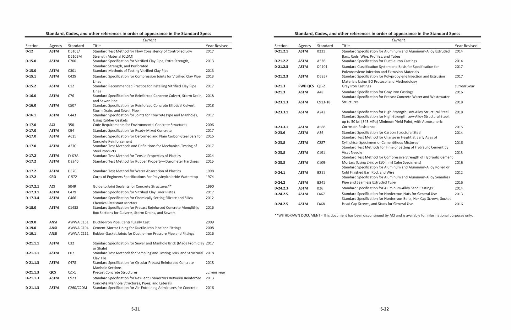
S-21
Section Agency Standard Title Year RevisedD-12 ASTM D6103/
D6103MStandard Test Method for Flow Consistency of Controlled Low Strength Material (CLSM)
2017
D-15.0 ASTM C700 Standard Specification for Vitrified Clay Pipe, Extra Strength, Standard Strength, and Perforated
2013
D-15.0 ASTM C301 Standard Methods of Testing Vitrified Clay Pipe 2013D-15.1 ASTM C425 Standard Specification for Compression Joints for Vitrified Clay Pipe
Lines2013
D-15.2 ASTM C12 Standard Recommended Practice for Installing Vitrified Clay Pipe Lines
2017
D-16.0 ASTM C76 Standard Specification for Reinforced Concrete Culvert, Storm Drain, and Sewer Pipe
2018
D-16.0 ASTM C507 Standard Specification for Reinforced Concrete Elliptical Culvert, Storm Drain, and Sewer Pipe
2018
D-16.1 ASTM C443 Standard Specification for Joints for Concrete Pipe and Manholes, Using Rubber Gaskets
2017
D-17.0 ACI 350 Code Requirements for Environmental Concrete Structures 2006D-17.0 ASTM C94 Standard Specification for Ready-Mixed Concrete 2017D-17.0 ASTM A615 Standard Specification for Deformed and Plain Carbon-Steel Bars for
Concrete Reinforcement2016
D-17.0 ASTM A370 Standard Test Methods and Definitions for Mechanical Testing of Steel Products
2017
D-17.2 ASTM D 638 Standard Test Method for Tensile Properties of Plastics 2014D-17.2 ASTM D2240 Standard Test Method for Rubber Property—Durometer Hardness 2015
D-17.2 ASTM D570 Standard Test Method for Water Absorption of Plastics 1998D-17.2 CRD C 572 Corps of Engineers Specifications For Polyvinylchloride Waterstop 1974
D-17.2.1 ACI 504R Guide to Joint Sealants for Concrete Structures** 1990D-17.3.1 ASTM C479 Standard Specification for Vitrified Clay Liner Plates 2017D-17.3.4 ASTM C466 Standard Specification for Chemically Setting Silicate and Silica
Chemical-Resistant Mortars2012
D-18.0 ASTM C1433 Standard Specification for Precast Reinforced Concrete Monolithic Box Sections for Culverts, Storm Drains, and Sewers
2016
D-19.0 ANSI AWWA C151 Ductile-Iron Pipe, Centrifugally Cast 2009D-19.0 ANSI AWWA C104 Cement-Mortar Lining for Ductile-Iron Pipe and Fittings 2008D-19.1 ANSI AWWA C111 Rubber-Gasket Joints for Ductile-Iron Pressure Pipe and Fittings 2016
D-21.1.1 ASTM C32 Standard Specification for Sewer and Manhole Brick (Made From Clay or Shale)
2017
D-21.1.1 ASTM C67 Standard Test Methods for Sampling and Testing Brick and Structural Clay Tile
2018
D-21.1.3 ASTM C478 Standard Specification for Circular Precast Reinforced Concrete Manhole Sections
2018
D-21.1.3 QCS QC-1 Precast Concrete Structures current yearD-21.1.3 ASTM C923 Standard Specification for Resilient Connectors Between Reinforced
Concrete Manhole Structures, Pipes, and Laterals2013
D-21.1.3 ASTM C260/C20M Standard Specification for Air-Entraining Admixtures for Concrete 2016
CurrentStandard, Codes, and other references in order of appearance in the Standard Specs
S-22
Section Agency Standard Title Year RevisedCurrent
Standard, Codes, and other references in order of appearance in the Standard Specs
D-21.2.1 ASTM B221 Standard Specification for Aluminum and Aluminum-Alloy Extruded Bars, Rods, Wire, Profiles, and Tubes
2014
D-21.2.2 ASTM A536 Standard Specification for Ductile Iron Castings 2014D-21.2.3 ASTM D4101 Standard Classification System and Basis for Specification for
Polypropylene Injection and Extrusion Materials2017
D-21.2.3 ASTM D5857 Standard Specification for Polypropylene Injection and Extrusion Materials Using ISO Protocol and Methodology
2017
D-21.3 PWD QCS QC-2 Gray Iron Castings current yearD-21.3 ASTM A48 Standard Specification for Gray Iron Castings 2016
D-23.1.3 ASTM C913-18Standard Specification for Precast Concrete Water and Wastewater Structures 2018
D-23.3.1 ASTM A242 Standard Specification for High-Strength Low-Alloy Structural Steel 2018
D-23.3.1 ASTM A588
Standard Specification for High-Strength Low-Alloy Structural Steel, up to 50 ksi [345 MPa] Minimum Yield Point, with Atmospheric Corrosion Resistance 2015
D-23.6 ASTM A36 Standard Specification for Carbon Structural Steel 2014
D-23.8 ASTM C287Standard Test Method for Change in Height at Early Ages of Cylindrical Specimens of Cementitious Mixtures 2016
D-23.8 ASTM C191Standard Test Methods for Time of Setting of Hydraulic Cement by Vicat Needle 2013
D-23.8 ASTM C109Standard Test Method for Compressive Strength of Hydraulic Cement Mortars (Using 2-in. or [50-mm] Cube Specimens) 2016
D-24.1 ASTM B211Standard Specification for Aluminum and Aluminum-Alloy Rolled or Cold Finished Bar, Rod, and Wire 2012
D-24.2 ASTM B241Standard Specification for Aluminum and Aluminum-Alloy Seamless Pipe and Seamless Extruded Tube 2016
D-24.2.3 ASTM B26 Standard Specification for Aluminum-Alloy Sand Castings 2014D-24.2.5 ASTM F467 Standard Specification for Nonferrous Nuts for General Use 2013
D-24.2.5 ASTM F468Standard Specification for Nonferrous Bolts, Hex Cap Screws, Socket Head Cap Screws, and Studs for General Use 2016
**WITHDRAWN DOCUMENT - This document has been discontinued by ACI and is available for informational purposes only.