pin with some failed parts shown in plate 1
TRANSCRIPT

^1^11r ^^. ^.. ^.. I ,.iiiliiW/^rrYYr^^ rWilu^i w.rlY^rrrYWwal^ld^" YY^YIYI^rIrIr1W^„w , i,1M^aiYWi^
A SUMMARY OF SOME TYPICAL STEEL FAILURES IN MACHINE PARTS ANDSTRUCTURAL SECTIONS
by
E.W. PIERCE,
CHIEF METALLURGIST SOUTH U.S. STEEL
The study of set-vice failures results in continued improvement in the use of metals. Theexperience gained in individual cases becomes of general value when a fundamental concept ofthe cause can be derived. In this way engineers have learned to avoid notch curets and otherstress raisers while other concepts such as stress corrosion arc not so well deliurd.
The examples given herein arc taken from mill laboratory files and present a summary ofthe circumstances of the failures with the probable causes. Division is made into three types offailures for the purpose of this discussion but it is not intended as a classification of all types offailures.
FATIGUE FAILURES
A considerable number of metal failures are classified as being of' the fatigue type. Thestresses involved are of the cyclic type and usually a considerable time elapses iu the service lifebefore failure occurs. Also a greater part of the service life is past before any damage is visibleby usual inspection methods. The fracture is characterized by a pattern which indicates thefocal point of' the failure and its progression across the section. 1Vhile in some cases a part may
he considered to have fulfilled its life expectancy, in others failure may be pfClllatilrC, because
of unfavorable selection of material or heat treatment, accidental abuse during Iabrication; in-stallation, or service. The hallowing examples are given to illustrate different causes of unsatis-factory performance.
(1). Failure of Pins in Conveyor Chains
AISI Type 4211 Stainless Steel
C .lIn P S Si CuiVi Cr .11n.36 .32 .017 .015 .23 .09 16 12.92 .01
Photo;raph-New pin with some failed parts shown in Plate 1.
Failure occurred in sonic cases after only one day of service. Hardness was -2 RockwellC across the section. The degree of' hardness was considered excessive and recommendationwas made to change the grade to AISI type 410, low carbon 12"„ Cr stainless <trrl, and t,> heattreat to about. 38 Rockwell C for the application.
(2) Serivce Failure of a Torque Converter Drive Shaft
AISI 4145 H Grade Steel
C .flit P S S i C'r l h,.45 .71 .017 .007 .28 .99 .1 J
ment.It was reported that failure had occurred after four years service in oil well drilling equip-
Hardness Tests-285 Brinell at surface , 277 Brinell at centre
36

#3 #2 #2 #4
Plate-1
#5
New pin # 1 with parts of pim failed in service. Note fatigue type failure in sample # 3 and areas of wear
in samples #4 and #5. Magnification 314 X

3!i
Murostrnctnre- Acicular structure characteristic of a normalized and drawn condition.
From visual examination it was apparent that failure resulted front fatigue cracking whichpropagated transversely across approximately two thirds of the section before complete failure.The origin of cracking was located by the concentric arcs on the broken end at it point near thekeyway as indicated by the arrow in the photograph. Considerable circumferential galling wasalso noted at the line of fracture. Although the keyway corners appeared to have ample radii itwas believed that the combination of the galling and the concentration of stresses around the key-way resulted in the fatigue failure.
(3j Pull Back Rod Failure
_fISI 9440 Grade Steel
C .lira I' S Si ,:Vi Cr .1 to.39 1.06 .021 .025 .51 .27 .32 .13
Hardness Tests
212 Brinell at surface
207 Brinell at center
Microstructure Ferrite and pearlite of rather coarse grain ranging from 1 to ti and avera-
ging #4 according to the A.S.T.M. rating chart.
The hardness values and the inicrostructure indicate that the rod had been slow-cooled afterforging and had been given no subsequent heat treatment.
The failure was caused by fatigue cracks which vrigittatcd at heavy Arasivu lllark^ of gvu,keson the key slot surface near the ends . These gouges may have been caused by improper fittingof the key. In addition to correcting this condition it was recommended to use AISI 1140 or8640 steel heat treated to obtain a fine grain structure and a surface hardness of approximately300 Brinell.
(4) Broken Rail Joint Bars
Typical chemical analysis -C.-l4 Mn.67 P.025 5,025 Si .11 17
Photograph of failures-Platc-2.
Hardness Tests----Head, web, and toe values ranged from 152 to 248 Brinell in eight bars.
.1lirrostrnctures---Considerable variations were noted in the amounts of ferrite in gran boundarynetworks enveloping fine pearlite colonies.
_lleehartical Properties-Considerable variations in strength values were totmd with only two ofeight failed bars satisfying the specification requirements of 70,000 p.s.i. yield point and 100,0E10p.s.i. tensile strength.
The eight failed joint bars were made during the years 1943-46 and the failures occurredduring 1950. Visual examination of all eight bars showed that the failures started in the headzones by fatigue cracking followed by sudden rupturing through the remainder of the sections.This is illustrated in the photograph . Pickling in acid revealed secondary cracks on both headand toe adjacent to the fractures in all bars. 'T'his condition was apparently caused by the bat-tering associated with the movement of the rail ends. The stressing effect of this movement wasindicated by the metal which was upset into the space between the rail ends.
An improvement in the uniformity of physical properties and microstructures would heexpected to result in improved service life. How ever, it was not certain that failures from

Plate-2
Photograph showing Various Degrees of Fatigue Penetration before Complete Failure of Rail Joint Bars.
Magnification X 9
40
fractures would be prevented since it was found that some of the failed bars were within specifica-tions.
It was recommended that a change in design should be considered in order to prevent theupsetting or pinching of metal between the rail ends.
Information obtained later tended to corroborate this recommendation. Experience hasshown that bars which have been removed from service in-order to grind out small cracks, appa-rently do not fail when placed back in service. It is believed that the removal of metal by grindingeliminates the contact of the bar with the rail ends and thus prevents the pinching and upsettingof metal.
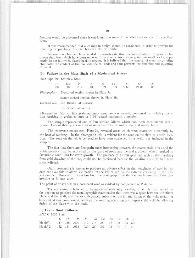
(5) Failure in the Main Shaft of a Mechanical Stirrer
AISI type 304 Stainless Steel
C Mn P S Si Cu Vi Cr .11n.06 .36 .019 .011 .39 .03 9.60 19.04 .05
Photographs-- Fractured section shown in Plate 3a
Macro-etched section shown in Plate 3b.
Hardness tests 176 Brinell at surface
161 Brinell at center
Microstructure. Normal fine grain austenite structure was severely coarsened by welding opera-tion resulting in grains as large as 0. 16" actual maximum dimension.
The sample represented one of four similar failures which had been encountered over aperiod of about three years in a lot of sixteen stirrers for aniline dye and starch baths.
The transverse macro-etch, Plate 3a, revealed areas which were coarsened apparently by
the heat of welding. In the photograph this is evident for the zone on the right at it weld loca-tion. The zone on the left is believed to have been coarsened by a weld not included in thesample.
The fact that there are fine-grain zones intervening between the coarse-grain areas and thewelds possibly may be explained on the basis of stress and thermal gradients which resulted infavourable conditions for grain growth. The presence of a stress gradient, such as that resultingfrom cold drawing of the bar, could not he confirmed because the welding assembly had beenstress-relieved.
Grain coarsening is known to produce an adverse effect on the toughness of steel but nodata are available to allow estimation of the loss caused by the extreme corsening in the sub-ject sample. However, it is evident from the photograph that the fracture failure was of the pro-gressive or fatigue type.
The point of origin was in a coarsened zone as evident by comparison of Plate 3a.
The coarsening is believed to be associated with long welding time. It was noted inthe section as polished for metallographic examination that there was a space between the stirrerblade and the shaft, and the weld depended entirely on the fill and fission of the weld metal. Abetter fit at this point would facilitate the welding operation and improve the %% Id by allowin('rfission of the blade with the shaft.
(6) Crane Hook Failures
AISI C 1035 Steel
C .1In P S Si Cu Vi Cr .110 FHook#1 .17 .36 .009 .017 . 14 .09 .16 .08 .05 nil
H oo k# 2 .32 .84 .013 .030 . 20 .02 .03 .04 .01 nil

41
Plate-3a.
Stirrer Shaft as Received Showing Progressive Nature of Failure. \I

.12
Plate-3b.
Macro-Etched Cross-Svcninn Adjacent !u Faihu '. \[

43
.lficrostructare Both samples had coarse grain structures of pearlite and ferrite.
The two samples examined included the tole threaded ends of the hooks showing the hlac-tures. These were of the progressive type originating in the base of the threads.
The 2 sample conforms to the AISI C 1035 grade which was specified for the application
but the #1 sample was C 1017 grade. I'urthermore neither sample appeared to have had anormalizing heat treatment as specified, because coarse grain structures of pearlite and ferrite wereobserved metallographically in both samples.
The location of the fractures in the V-threads resulted from stress concentration and re.commendation was made to decrease this effect by redesign of the thread contour.
(7) Premature Failures of Back Up Arbor Rolls
Chemical Analysis:
C Mn P S Si vi Cr Mo.23 .60 .015 .015 .18 3.48 1.57 .20
Each of three rolls had broken at the journal adjacent to the body of the roll and thefracture was at approximate right angle to the longitudinal axis.
Examination of the fractures indicated that they were of the progressive type. Theconcentric circular lines associated with tltu type of fracture indicated the points of origin to bebelow the 'urfacc.
The nuclei for the progressive fractures were readily apparent as flakes which was madeadjacent to the fracture.
Failures which are caused by defective steel are not common because preliminary testingusually eliminates such material from use.
FAILURES BY CRACK PROPAGATION
Brittle failures of ductile structural steels sometimes occur in structures which apparentlyhave not been subjected to static loading in excess of normal. In studies of such cases it is ad-vantageous to determine the point of origin of the failure especially when the fracture may ex-tend for many feet. Closer study of a limited zone can then be made to determine whether anoriginal steel defect or some alteration of* the normal metal has caused the failure. The followingexamples are given to show how this procedure was used.
(8) Failure of a Wale Beam in a Breakwater
Chemical Analysis
C Mn P S Si.24 .70 .011 .028 .05
Photograph Area of initial failure shown in Plate 4.
Tensile and Bend Tests
Tensile Strength Yield Point %p.s.i. p.s.i. Elongation in 8" 180" Bend
68,610 41,310 25.2 Ok- no crackin;
Specification (-)(),00() -- 1.5011 O00 21.972,000 I'.S.

^^ r^ «1 :: .!'.uuu , . L.. ,ILL fl L 11111L1U [ 1 Il' . , r.+r.
44
Fracture in Flange of CB-103 x 72$ turnNote area of Initial failure Daimon t ch-cut hole end left eege. MegnSticaticn I e
Plate-!

Hardness
average
at edge of torch-cut hole
Rockwell B
78
98
Equivalent Brinell
144
288
The failure occurred by sudden rupturing through most of the beam section during a severestorm. The sample for examination included the failure but had to be saw-cut to separate theparts and expose the fracture. Part of the fracture is shown in Plate 4 and it may be noted thatthe left zone, between the torch-cut hole and the edge of the flange, had been worn smooth.This indicates that failure had occurred through this zone at some time prior to therest of the rupturing. Metallographic examinations along this first section of the failure showedthe normal microstructure of ferrite and pearlite. A condition which may have acted unfavor-ably and initiated the failure, was noted in the rough irregular contour of the torch-cut holes.These irregularities would result in stress concentration which together with the increase in hard-ness noted above would favor the start of a crack at one of the holes. Although it is commonpractice to torch-cut holes as was done in this case, the harmful effects noted could be avoided bya smoother cut or by reaming.
(9) CB.Section Ruptured in Service as a Walking Beam.
Chemical Analysis
0.125 Mn.64 p.008 S.032 Si.06
Hardness 123 to 126 Brinell
Complete failure had occurred through one flange and the web of the beam weldment.The failure was typical of others which had occurred previously. The weldment was used asa walking beam in oil well pumping service. It may be noted that failure extended across theflange at the reduced width where 90' corners were produced by torch cutting. At one cornerthe point of origin was defined by concentric rings on the fracture face indicating an initial pro-gressive type failure.
The normal microstructure consisted of fine lamellar pearlite and ferrite but at the torch-cut edge a zone of martensite was detected. The association of the torch-cut corners and theprogressive type fracture across the flange indicate that the failure originated in the metal affec-ted by the torch cutting. The abrupt change in section located stress concentrations in the har-dened zones and caused a fatigue or progressive crack to develop. It is obvious that the strengthof the beam would be considerably reduced by the decrease in flange width from 10" to 7'. Ifthis reduction was required by the design of the walking beam assembly, it should have beendone by flaring to avoid sharp corners and consequent points of stress concentration. As anadded precaution torch-cut zones could have been post-heated to decrease the hardening effect.
( 10) Failure of a Channel in a Riveted Compression Member of a Bridge.
Chemical Analysis
C.24 Mn.48 p.015 S.029 Si.06
Tensile and Bend Tests
Tensile Strength Yield Point o,'Elongation 180' Bendp.s.i. p.s.i. in 8"65,840 37,130 25 Ok-no cracking
It was learned that the original section, over 50 feet long, was trucked about 250 milesto the bridge site during winter with sub-zero temperatures prevailing and continuing duringerection. Since the subject member of the bridge was designed as part of a compressive memberand a tension failure had occurred, it was believed that the flange had been subjected to someshock before being placed in the structure.

16
Macro-etching of the flange sections revealed that several very shallow tears had startedin the skirted areas on the sides of the rivet holes. It was observed microscopically that the skirtedmetal was severely cold worked while the area adjacent to it had a lesser amount decreasing tothe normal structure of ferrite and pearlite. The total depth of cold worked area including theskirted zone was approximately .03".
The severely cold worked skirted areas are not abnormal for punched rivet holes butunder conditions of impact or suddenly applied high stress such areas would serve to start cracks.The notch effect of small tears in cold worked metal would be most detrimental in the sub-zeroweather. Thus it seemed likely that some impact force was responsible for the failure prior toerection.
CORROSION FAILURES
Corrosion of structural low alloy and carbon steels is considered a natural occurrence andprotective coatings arc commonly used. However, when stainless steels are used it is quite oftenincorrectly assumed that corrosion may no longer he a problem. Accordingly, failures of stain-less steel cause much concern. Occasionally it is it combination of conditions that cause thefailures. Sometimes the most suitable type of stainless steel has not been selected for the applica-tion or the fabrication methods cause unfavourable alteration of a normall y statistactory structure.The following examples illustrate a few of these possibilities.
(11) Thread Fitting Failed in Service in a Pressure Assembly
AISI Type 316 Stainless Steel
C Mn P S Si Cu Vi Cr 11,.06 .55 .030 .016 .69 .14 12.68 18.93 1.84
Photograph Part as sectioned for macro-etch testing is shown in Plate 5.
A threaded fitting developed internal cracks after being put into service in a pressure as-sembly. Five parts had been machined from a two foot length of 3" diameter centcrless groundbar stock. It was reported that three parts leaked immediately and two parts were satisfactoryin service. The pressure assembly was operated in a temperature range of -401) to 60(1 F. at10,000 p.s.i. pressure. Materials contained were compounds of phosphorus, aluminium, silicon,and sometimes chlorine.
The macro-etch tests as shown in the photograph revealed radial internal cracks. Two ofthe branch-like cracks penetrated the surface of the shaft at the junction with the threaded sectionbut this is not visible in the photograph . The leakage probably occurred at these two points offailure.
Metallographic examination in the zone of' the failure revealed intc•rgranular cracks out-lining grain boundaries in a network pattern . The microstructure was austenite with numerousferrite stringers. The steel was in the annealed condition as indicated by the fact that there wereno undissolved carbides.
The cause of failure was not definitely established but the presence of' chlorides, heat andpressure are known to he unfavourable factors in resistance to stress corrosion. On the basis ofthe metallographic examination and the conditions known to exist during operation, it is be-lieved that the failure was the result of stress corrosion.
( 12) Failure in Service of a Water Turbine Ring.
:IISI Type 403 Stainless Steel
C Mn P S Si .\i C.710 .41 .017 .007 .37 .19 12.88

47
Plate-5

„__ . ill l^il , l.JJlll. ►r.rurrrr^rrr :^i:^^.rr.r.^ ^. ^ ^,^ • iWr.ru+rrrrW. ^ ^," ,.
18
Photograph Sample containing transverse cracks shown in Plate 6.
Hardness 321 Brinell
A water turbine ring developed a series of transverse cracks after nine months service.The material had been cold formed from a 2"x6" rolled section to a 15' diameter ring. Thering was oil quenched from 1700°F., tempered at 100°F and shruck fit on a turbine rotor.
Magnaflux testing revealed the radial discontinuity running longitudinally as shown on thetransverse face of the sample. In addition, hairline-indications parallel with the originally notedcracks, 2, 3 and 4 were observed in one keyway, but are only slightly apparent in the photograph.
Metallographic examination showed a tempered martensite structure with numerousferrite stringers. The failures were intercrystallinc and branched.
The cause of failure was not definitely determined because of' lack of information regardingsuch variables as operating temperatures, stresses in the turbine ring and water source suppliedto the turbine. However, the type of failure was characteristic of stress corrosion.
(13) Severe Corrosion of a Stainless Steel Coupling
AISI Type 303 Stainless Steel
C Mn P S Si VI Cr .tto.09 .99 .017 .280 .45 9.10 17.86 .43
The coupling had been in service immersed in sulphurous liquid. After only a shortperiod of time, the part had been so weakned and deteriorated by corrosion that it had to beremoved from service.
Metallorgraphic examination revealed an austenitic microstructure with no undissolvedcarbides but with a heavy concentration of sulphide inclusions throughout. The cracks weretransgranular.
It was considered that the failure was associated with the fact that type 303 stainless steelis not suitable for service in a sulphurous liquid. It was recommended that a grade such astype 316, 18-8 Mo, stainless steel he used.
(14) Failure of Nozzles in the Extrusion of Zinc into Die Castings
AISI Type 303 Stainless Steel
C Mn P S Si Cu Ni Cr Mo SeSatisfactoryNozzle . 07 1.08 . 176 0 . 014 .66 . 23 9.64 17 . 76 .15 .31FailedNozzle . 07 .84 . 160 .012 . 65 .03 9.60 18 . 00 .07 .31
Photograph: View of half section of nozzle in plate 7 showing the point of failure.
One nozzle failed very rapidly after only six extrusions because of penetration of the wallthickness by the molten zinc. The other, which was secured for comparison, had been in servicefor approximately six months without failure.
The chemical analysis of the two nozzles were very similar except for manganese andthe residual copper and molybdenum contents but these differences did not appear to be significant.
Longitudinal macro-etch tests revealed sound quality in both. The satisfactory nozzleshowed coarse grain structure contrasted to fine grain in the failed nozzle. This difference wasalso observed in the microstructures but was not believed to he of significance in this application.
i

49
Plate-6
Water Turbine Ring Sample as Ma,gnaftuxrd to Show Cracks.Magnification X 8

^ilflLlft^ . 1 11..1.1' M. n .'I'MIL Ltl
Plate-7
half S( cliun if' Siainlvs. ' z-I( Sln ^cinr Point (1f' P('111,11-alinnlis-Mu'trn Zici• in Extrn i m l'i'pa',,.
M.1,1, < tiwl \ 1.

51
In metallugraphic examinations the zinc pellet ration was G,und to be progressive along theinner wall. It appeared that penetration occurred by forination of a zinc - iron alloy. In thefailed nozzle the laver of" zinc plus zinc - iron alloy measured about .027' deep while in the satis-factory nozzle a niaxinntm of .010" drpth was found with some portions free of penetration. Bothnozzles had microstructures consisting essentially of austenite but the failed nozzle hadexcessive carbide precipitation compared to practically none in the satisfactory nozzle. Thiswas a good indication that tit(- failed uozzlc had ]wen heated to a cr ti^ideral^l^ higher tempera-tue than the other.
It is reported in the literature that the attack of iron by zinc begins at about 42(1 C.(788°F.) and increases rapidly with rise of' temperature. The zinc was extruded through thesubject nozzles supposedly maintained at a temperature of' 720 to 7601. by means of heatingwith gas flames directed on the tapered 01) of the nozzles. Since other characteristics suchas chemistry and soundness were very similar, it appears probable that excessive operating tem-peratures accounted for an accelerated rate of zinc-iron alloy lormation in the failed nozzle.The rapid penetration of the zinc-iron alloy formation to the surface was probably related tothe temperature gradient existing between the nozzle bore and the heated surface. A point ofhigher temperature along the bore probably was the location of an accelerated attack whichprogressed along the temperature gradient at increasing rate as the point of heating wasapproached.
Because of the critical temperature conditions existing in the service of the nozzles andbecause of the mutual solubility of zinc and iron, the application of stainless steel for this purposecannot be guaranteed. For possible successful operation it appears essential to control tempera-ture precisely at the minimum required for the die-casting operation and also to heat the nozzleas uniformly as possible.
1. J.W. Mellor, "A Comprehensive Treatise on Inorganic and Theoretical Chemistry,"Vol. XIII , P. 543.