picon ii console controller - fuel control solutions ... ii general information & warranty...
TRANSCRIPT

PIcon II Console Controller
Installation Guideand
User Reference Manual

© Copyright 2017Progressive International Electronics
1106 Great Falls Court, Suite G
Knightdale, NC 27545
www.pie-corp.com

PICON II CONSOLE CONTROLLER
User Reference ManualCONTENTS
GENERAL INFORMATION & WARRANTY. . . . . . . . . . . . . . . . . . . . . . . . . . . . . . . . . . . . 1General Information. . . . . . . . . . . . . . . . . . . . . . . . . . . . . . . . . . . . . . . . . . . . . . 1PIcon II Manufacturer's Warranty.. . . . . . . . . . . . . . . . . . . . . . . . . . . . . . . . . . . . . 3System Warnings.. . . . . . . . . . . . . . . . . . . . . . . . . . . . . . . . . . . . . . . . . . . . . . . . 4Avertissements Système. . . . . . . . . . . . . . . . . . . . . . . . . . . . . . . . . . . . . . . . . . . . 5
INSTALLATION. . . . . . . . . . . . . . . . . . . . . . . . . . . . . . . . . . . . . . . . . . . . . . . . . . . . . . . 6General Installation Guidelines. . . . . . . . . . . . . . . . . . . . . . . . . . . . . . . . . . . . . . 6Quick Startup. . . . . . . . . . . . . . . . . . . . . . . . . . . . . . . . . . . . . . . . . . . . . . . . . . . 8
OPERATION. . . . . . . . . . . . . . . . . . . . . . . . . . . . . . . . . . . . . . . . . . . . . . . . . . . . . . . . . 9Introduction. . . . . . . . . . . . . . . . . . . . . . . . . . . . . . . . . . . . . . . . . . . . . . . . . . . . 9Display and Status Indicators. . . . . . . . . . . . . . . . . . . . . . . . . . . . . . . . . . . . . . . 11Sales. . . . . . . . . . . . . . . . . . . . . . . . . . . . . . . . . . . . . . . . . . . . . . . . . . . . . . . . 13Special Select Functions. . . . . . . . . . . . . . . . . . . . . . . . . . . . . . . . . . . . . . . . . . . 14Operator Access. . . . . . . . . . . . . . . . . . . . . . . . . . . . . . . . . . . . . . . . . . . . . . . . 17
OPR 1 — Read Reports (Refer to Reports Section, Read Reports). . . . . . . . . 17OPR 2 — Print Reports (Refer to Reports Section, Print Reports). . . . . . . . . . 17
MANAGER. . . . . . . . . . . . . . . . . . . . . . . . . . . . . . . . . . . . . . . . . . . . . . . . . . . . . . . . . 18Manager Access. . . . . . . . . . . . . . . . . . . . . . . . . . . . . . . . . . . . . . . . . . . . . . . . 18
Manager Mode MGR 1 — Program Product Price. . . . . . . . . . . . . . . . . . . 19Manager Mode MGR 2 — Read Reports (Refer to Reports Section, Read
Reports). . . . . . . . . . . . . . . . . . . . . . . . . . . . . . . . . . . . . . . . . . . . 19Manager Mode MGR 3 — Print Reports (Refer to Reports Section, Print
Reports). . . . . . . . . . . . . . . . . . . . . . . . . . . . . . . . . . . . . . . . . . . . 19Manager Mode MGR 4 — Clear Resettable Totals. . . . . . . . . . . . . . . . . . 19Manager Mode MGR 5 — Set Date and Time. . . . . . . . . . . . . . . . . . . . . . 20Manager Mode MGR 6 — Beeper Settings. . . . . . . . . . . . . . . . . . . . . . . . 21Manager Mode MGR 7/Program Mode PGM 13 — Program
Operator/Manager PIN Codes. . . . . . . . . . . . . . . . . . . . . . . . . . . 22Manager Mode MGR 8 — Shift Report Setup. . . . . . . . . . . . . . . . . . . . . . 23Manager Mode MGR 9 — Set Auto Receipts. . . . . . . . . . . . . . . . . . . . . . . 24Manager Mode MGR 10 — Set Default MOP. . . . . . . . . . . . . . . . . . . . . . 24
REPORTS. . . . . . . . . . . . . . . . . . . . . . . . . . . . . . . . . . . . . . . . . . . . . . . . . . . . . . . . . . 25Read Reports. . . . . . . . . . . . . . . . . . . . . . . . . . . . . . . . . . . . . . . . . . . . . . . . . . 25
Operator Mode OPR 1/Manager Mode MGR 2 — Read Reports. . . . . . . . 25Print Reports. . . . . . . . . . . . . . . . . . . . . . . . . . . . . . . . . . . . . . . . . . . . . . . . . . . 27
Operator Mode OPR 2/Manager Mode M 3 — Print Reports. . . . . . . . . . . 27

PROGRAMMING. . . . . . . . . . . . . . . . . . . . . . . . . . . . . . . . . . . . . . . . . . . . . . . . . . . . 30Program Mode PGM 1 — Pump Type. . . . . . . . . . . . . . . . . . . . . . . . . . . 31Program Mode PGM 2 — Pump Configuration. . . . . . . . . . . . . . . . . . . . . 32Program Mode PGM 3 — Product Name Assignment. . . . . . . . . . . . . . . . 33Program Mode PGM 4 — Set Dollar/Volume Default. . . . . . . . . . . . . . . . 34Program Mode PGM 5 — Set Dollar or Cash/Credit. . . . . . . . . . . . . . . . . 35Program Mode PGM 6 — Set Gallon/Litre Receipt. . . . . . . . . . . . . . . . . . 35Program Mode PGM 7 — Handle for Authorization. . . . . . . . . . . . . . . . . . 36Program Mode PGM 8 — Set Dollar/Volume/PPU Decimals. . . . . . . . . . . 36Program Mode PGM 9 — Set Language. . . . . . . . . . . . . . . . . . . . . . . . . . 37Program Mode PGM 10 — Stacked Sales (Yes/No). . . . . . . . . . . . . . . . . . 37Program Mode PGM 11 — ATG Activation.. . . . . . . . . . . . . . . . . . . . . . . 38Program Mode PGM 12 — Clear Event Log. . . . . . . . . . . . . . . . . . . . . . . 38Program Mode PGM 13/Manager Mode MGR 7 — Program
Operator/Manager PIN Codes. . . . . . . . . . . . . . . . . . . . . . . . . . . 38Program Mode PGM 14 — Drive Away Activation. . . . . . . . . . . . . . . . . . . 39Program Mode PGM 15 — Program Tax Percentage. . . . . . . . . . . . . . . . . 40Program Mode PGM 16 — Pump Interface (PIPORT/RS232). . . . . . . . . . . 40Program Mode PGM 60 — Pump Specific Settings. . . . . . . . . . . . . . . . . . 41
DIAGNOSTICS. . . . . . . . . . . . . . . . . . . . . . . . . . . . . . . . . . . . . . . . . . . . . . . . . . . . . . 43PIcon II Internal Diagnostics. . . . . . . . . . . . . . . . . . . . . . . . . . . . . . . . . . . . . . . . 43
Show Dispenser Information.. . . . . . . . . . . . . . . . . . . . . . . . . . . . . . . . . . 44Display Version Information. . . . . . . . . . . . . . . . . . . . . . . . . . . . . . . . . . . 44Download Print Header. . . . . . . . . . . . . . . . . . . . . . . . . . . . . . . . . . . . . . 44Configure Pump. . . . . . . . . . . . . . . . . . . . . . . . . . . . . . . . . . . . . . . . . . . 45
PIcon II Code Update. . . . . . . . . . . . . . . . . . . . . . . . . . . . . . . . . . . . . . . . . . . . 46PIcon II Basic Troubleshooting. . . . . . . . . . . . . . . . . . . . . . . . . . . . . . . . . . . . . . 47
PATENTSProgressive International products are manufactured or sold under one or more of thefollowing U.S. patents.
5,790,4105,831,8615,694,3265,663,887
5,557,5295,394,3365,361,2165,270,943
5,108,74220,140,074,282
HISTORY OF DOCUMENT REVISIONSRev. 1.0
Initial ReleaseRev. 1.1
Added System Warnings in FrenchRev. 2.0 C Under Quick Startup, added step: Manager Mode MGR 1, Program Product Price Program Mode PGM 60, Pump Specific Settings C Under Manager Mode M 3, Print Reports, added: PRN 15, Print Interrupt Log
PRN 16, Print Application LogPRN 17, Print Debug Info
C Under Programming, added:PGM 12, Clear Event LogPGM 13, Program Operator/Manager PIN CodesPGM 14, Drive Away Activation
C Updated Table: Dispenser-Specific Configurations C Added PIcon II Basic TroubleshootingRev. 2.1 C Under Programming, added:
PGM 15, Program Tax PercentagePGM 16, Pump Interface (PIPort / RS422)PRN 18, Print Diagnostics Report
The most recent release of the PIcon II Installation Guide and User Reference Manual isalways available at pie-corp.com in .pdf format. For assistance in the field, be sure todownload the PIE Support App from the Google Play Store, or use the QR code or linkbelow.
https://play.google.com/store/apps/details?id=com.piecorp.pie_inc_support
COPYRIGHTCopyright © 2017 Progressive International Electronics, Inc. All rights reserved. No part ofthis publication may be reproduced, stored in a retrieval system or transmitted, in any form orby any means, electronic, mechanical, photocopying, recording, or otherwise, without theprior written permission of Progressive International Electronics, Inc.
All brands or product names are trademarks or registered trademarks of their respectivecompanies.

PIcon II General Information & Warranty
GENERAL INFORMATION & WARRANTY
General InformationThe PIcon II is an economical, full-featured console designed to provide control of up to 16
fueling positions. While most consoles can only control one type of fuel dispenser, the PIcon II
may be configured to run any major brand electronic or mechanical dispenser. This is
accomplished through the use of brand-specific Progressive International PI DBoxes that contain
the unique circuitry required to interface to each individual dispenser brand. An alternative to
this solution is the use of configurator boxes, supplied by PIE, along with the dispenser
manufacturer’s DBox.
PIcon II provides full features, yet is very simple to install and operate. Due to meticulous design
of the keyboard and display layout, keystrokes are kept to a minimum during programming setup
and normal operation modes.
Standard features provided by the PIcon II for efficient control of fueling dispensers include:
C Full featured console which includes prepay/postpay, preset, drive-away alerts, stacked sale,
cash/credit operation.
C Management features including dispenser, shift and station totals, management security,
prices programmed by product.
C Easy to read LCD display.
C Controls up to 16 fueling positions — including all major electronic and mechanical
dispensers and blending dispensers.
C Audible alerts for call, drive-away and collect, with low- and high-volume settings.
C Memory backup to retain data in the event of power outage.
Rev 2.1 February 20171

PIcon II General Information & Warranty
C Built-in hardware clock to time stamp all reports.
C Compact size allowing convenient counter-top positioning while utilizing a minimum
amount of valuable counter space.
C Standard printer interface for use with most low-cost parallel printers.
C Ease of installation — console wires directly into dispenser distribution boxes or PI DBoxes.
Prior to installation or operation of the PIcon II, please review each section of this manual and
other pertinent equipment manuals to familiarize yourself with the system.
Rev 2.1 February 20172

PIcon II General Information & Warranty
PIcon II Manufacturer's WarrantyProgressive International Electronics, Inc. (SELLER) warrants to the Purchaser of the PIcon II
fuel control equipment manufactured by Seller against defects in material or workmanship for
one (1) year from date of shipment. Seller will replace or repair defective parts or replace and
issue credits to the Purchaser's account in accordance with the following Conditions of Warranty.
CONDITIONS OF WARRANTY
1. Credit will be applied only when the completed warranty request form and the defective partsare received and inspected.
Decisions to repair or replace defective equipment are solely at the discretion of PIE.
2. When parts shipments are made prior to receiving the required warranty request and defectiveparts, they will be billed to the Purchaser.
3. In all cases, approved warranty requests will be expedited by issuing the appropriate credit tothe Purchaser's account and shipping replacement parts.
4. Credits will not be issued for parts and no cash refunds for warranty credits will be made.
5. All components and parts must be returned to the factory prepaid, and in turn, replacementcomponents and parts will be returned prepaid by the factory.
6. Seller's warranty applies only if the equipment has been installed and used in accordance withSeller's instructions. The warranty is void if any unauthorized alteration or addition has beenmade to the equipment or if it has been subject to damage caused by abuse, misapplication,accident or improper operation.
7. The Seller's liability for any damages, including contribution and indemnification, arising outof or in any way connected with the supplying of the equipment or its use, shall not in anycase exceed the cost of repair of the equipment as herein provided. Upon expiration of thewarranty, all such liability, as well as any other liability, shall terminate.
8. Nothing contained herein shall make the Purchaser, its agents or employees, an agent orrepresentative of Seller and Seller assumes no responsibility of any act, omission,representation or warranty by the Purchaser or anyone else except as expressly stated herein.
9. The final Decision as to the validity of any claims arising under the warranty shall bedetermined solely by the Seller.
THE FOREGOING WARRANTY IS IN LIEU OF ALL OTHER WARRANTIES, EXPRESSEDOR IMPLIED, INCLUDING, BUT NOT LIMITED TO, THE IMPLIED WARRANTIES ORMERCHANTABILITY AND FITNESS FOR A PARTICULAR PURPOSE WHICH EXCEEDTHE AFORESAID OBLIGATIONS AND ARE HEREBY DISCLAIMED AND EXCLUDEDBY SELLER.
Rev 2.1 February 20173

PIcon II General Information & Warranty
System Warnings
Safety hazards are inherent with all electrical equipment. Standard precautions must be taken atall times during installation and operation of the PIcon II systems. In addition to normalelectrical precautions, the following points should be noted during installation.
• Installation must comply with the National Electrical Code, as well as Federal,State/Provincial, Local, and all applicable codes.
• High voltages are present in the PIcon II components, as well as the equipment to whichit is attaching. To prevent personal injury or equipment damage, disconnect all powerbefore proceeding with installation.
• PIcon II equipment must be installed in non hazardous areas. The main box must beprotected from severe vibration, extreme temperatures and excessive humidity.
• All equipment connected to the PIcon II must be UL-approved and mounted in anonhazardous location using standard RS232 communication.
For Use in USA
Installation of the PIcon II fuel control system must comply with the requirements of the NationalElectrical Code (NFPA 70), the Automotive and Marine Station Code (NFPA 30A), and allFederal, State, Local, and applicable safety codes.
For Use in Canada
Installation of the PIcon II fuel control system must comply with the requirements of theCanadian Electrical Code, the Flammable and Combustible Liquid Code, and all Federal,Provincial, Local and applicable safety codes.
****
The installation of the systems covered by this manual in conjunction with equipment notUL Listed has not been evaluated by the Underwriters Laboratories and is outside theintended us of this equipment. Warning: All dispensing equipment discussed in thismanual is not UL Listed and the combination has not been evaluated by UnderwritersLaboratories.
Rev 2.1 February 20174

PIcon II General Information & Warranty
Avertissements Système
Risques de sécurité sont inhérents à tous les équipements électriques. Les précautions standarddoivent être prises à tous les fois pendant l'installation et le fonctionnement des systèmes PIconII. En outre à la normale électrique précautions, les points suivants doivent être pris pendantl'installation.
• L'installation doit se conformer au Code national de l'électricité, ainsi que fédérales,d'État/provincial, Local, et tous les codes applicables.
• Hautes tensions sont présentes dans les composants PIcon II, ainsi que l'équipementauquel il est la fixation. Pour prévenir les blessures ou des dommages matériels,débrancher l'alimentation avant procéder à l'installation.
• Équipements PIcon II doit être installé dans les zones non dangereux. La boîte principaledoit être protégé de fortes vibrations, aux températures extrêmes et à l'humidité excessive.
• Tous les équipements connectés à l' PIcon II doit être homologué UL et monté dans unnon dangereux emplacement en utilisant la communication RS232 standard.
Pour Utilisation aux Etats-Unis
L'installation du système de commande de carburant PIcon II doit se conformer aux exigences dela National Electrical Code ( NFPA 70 ), l' Automobile et le Code Station Marine ( NFPA 30A ),et tous les fédéral, État, local, et les codes de sécurité applicables.
Pour Utilisation au Canada
L'installation du système de commande de carburant PIcon II doit se conformer aux exigences dela canadienne Electrical Code, le Code liquides inflammables et combustibles, et tous les fédéral,provinciaux, étatiques, Codes de sécurité locales et applicables.
****
L'installation des systèmes couverts par ce manuel en conjonction avec un équipement nonULInscrite n'a pas été évalué par les Underwriters Laboratories et est en dehors del'utilisation prévue de cet équipement. Attention: Tous les équipements de distributiondiscuté dans ce manuel ne est pas UL et la combinaison n'a pas été évaluée parUnderwriters Laboratories.
Rev 2.1 February 20175

PIcon II Installation
INSTALLATION
General Installation Guidelines
The basic PIcon II system consists of several components — the PIcon II console, interconnect
box, PI DBox and parallel printer cable. Refer to Diagram: PIcon II Port and Keyboard
Layout, which shows the various connections of the PIcon II system, including the port for
optional printer. If further assistance is required, please contact your PIcon II dealer.
To install the PIcon II:
1. Place the console at the checkout counter of the station.
2. If using the PI DBox, refer to the PI DBox Installation Guide for detailed installation
instructions. Attach the PIcon II system to the dispenser data distribution equipment for
the appropriate dispenser type.
3. If a printer is to be used with the PIcon II, attach the printer cable to the connector on the
back of the parallel printer and the other end to the printer port on back of the PIcon II.
4. If using the PI Configurator and the dispenser manufacturer’s DBox, refer to the PI
Configurator Installation Guide and the dispenser manufacturer’s DBox installation guide
for detailed instructions. Mount under the counter or on a wall adjacent to the console,
not more than five feet away. Using the PIcon II cable, connect the configurator to the
PIcon II’s PI port.
5. Upon completion, apply power to all the components of the PIcon II system and perform
Quick Startup as described on the following page. Then commence programming, as
outlined in Programming Section of this manual. Note: An uninterruptable power supply
is recommended for clean power.
Rev 2.1 February 20176

PIcon II Installation
Rev 2.1 February 20177

PIcon II Installation
Quick Startup
This quick startup procedure lists the order and minimal programming steps for operation of the
PIcon II. For more detailed explanations or for programming of optional modes, refer to the
Programming Section of this manual.
1. Program Mode PGM 1 — Pump Type
Note: Pump Type must be selected before other programming can be completed.
2. Program Mode PGM 2 — Dispenser Setup Information
3. Program Mode PGM 3 — Product Information
4. Manager Mode MGR 1 — Program Product Price
5. Program Mode PGM 60 — Pump Specific Settings
Note: Certain dispenser brands require that each Model Type is configured for
proper functionality.
Prior to performing Quick Startup, press <SELECT> twice and check to ensure that the date is
correct. If incorrect, change date as explained in Manager Mode Section, MGR 5 — Set Date
and Time. If date is correct, calculate restricted code by multiplying the current month, times the
day, plus the year. For example, if the date were December 10, 2000, the restricted code would
be calculated as follows:
12 X 10 + 2000 = 2120 Restricted access code would be 2120.
Rev 2.1 February 20178

PIcon II Operation
OPERATION
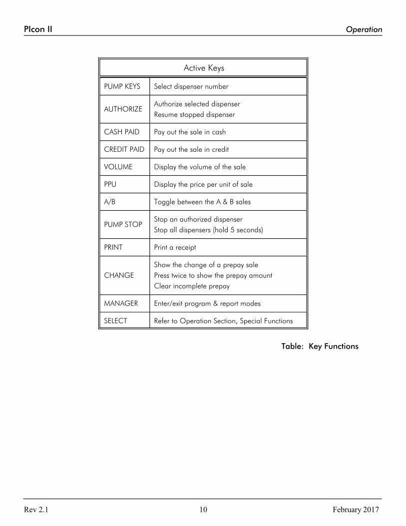
IntroductionIn Operation Section, all functions available to the operator of the PIcon II are outlined. Table:
Key Functions on the following page provides brief descriptions of key functions. Also, refer to
Diagram: PIcon II Port and Keyboard Layout, below, for general locations of various keys,
indicators and display.
There are two types of operations for the operator:
• Dispenser control — Initiated by pressing the appropriate pump select key, followed by
the keys corresponding to the command for the PIcon II to make upon that dispenser.
• Select functions — Provide the operator access to the time and date, operator shift report,
shift change, and console deactivation functions.
Rev 2.1 February 20179
PIcon II Operation
Active Keys
PUMP KEYS Select dispenser number
AUTHORIZEAuthorize selected dispenser
Resume stopped dispenser
CASH PAID Pay out the sale in cash
CREDIT PAID Pay out the sale in credit
VOLUME Display the volume of the sale
PPU Display the price per unit of sale
A/B Toggle between the A & B sales
PUMP STOPStop an authorized dispenser
Stop all dispensers (hold 5 seconds)
PRINT Print a receipt
CHANGE
Show the change of a prepay sale
Press twice to show the prepay amount
Clear incomplete prepay
MANAGER Enter/exit program & report modes
SELECT Refer to Operation Section, Special Functions
Table: Key Functions
Rev 2.1 February 201710

PIcon II Operation
Display and Status IndicatorsThe LCD display provides the operator with all sale information for the dispenser selected. It
also provides data such as time/date and shift totals reports when using the select functions.
Listed below in Table: Display Data are the various fields of data which may appear in the
display area, along with a brief description of each field.
Display Description
Pump #Indicates the current/active dispenser #/fueling position. Further key entry, such as authorization or payment willapply to the current dispenser #.
Hose # Indicates the active hose at a fueling position.
Sale TypeIndicates the method of payment selected for a sale — Cash (C) or Credit (R).
Sale #Indicates which sale is selected — Current sale or previoussale respectively (A or B respectively)
Product # Indicates the product type for the displayed sale.
AmountType
Indicates type of data being displayed in the amount field.($) Sale amount, (V) Volume, (CG) Change amount, (LM)Prepay Limit, (C) Cash, (R) Credit
Amount Indicates the value, dollar or volume of the active sale.
EnteredValue
Displays any data entered on the numeric keypad.
Table: Display Data
Rev 2.1 February 201711

PIcon II Operation
The LEDs below each of the pump numbers are the status indicators for that particular
dispenser/fueling position. The green LED on the top indicates Call/In Use. The red LED on the
bottom indicates Collect/Stopped. Table: LED Indicators, below, shows the various states
these LEDs represent for each dispenser/fueling position.
Green LED Red LED Status
Fast Flash — Call for service
On Solid — Authorized
— Slow Flash Collect "A" Sale
— On Solid Dispenser Stopped
Fast Flash and Fast Flash Drive-Away
Slow Flash and Slow Flash Collect "A" and "B" Sales
Table: LED Indicators for Dispenser/Fueling Positions
Rev 2.1 February 201712

PIcon II Operation
SalesAuthorization must be made for a sale as either a Postpay, Preset Postpay, or Prepay sale. Table:
Sales Procedure, below, describes the sequence for completing each type of authorized sale.
Note: An actual key action is indicated by <____>.
Sale Type Procedure
Postpay
To authorize a dispenser for a Postpay/Fillup operation, pressthe appropriate <PUMP #> key and then press the red<AUTHORIZE> key. To pay out the sale on the console, pressthe <PUMP #> key. Press either <CASH PAID> or <CREDITPAID> key. To print a receipt, press <PRINT>.
PresetPostpay
To authorize a dispenser for a preset amount, press theappropriate <PUMP #> key and then enter the preset amounton the numeric keypad. Press the red <AUTHORIZE> key. Topay out the sale on the console, press the <PUMP #> key. Press either <CASH PAID> or <CREDIT PAID> key. To printa receipt, press <PRINT>. Note: The amount entered on thenumeric keypad appears on the display in the ENTERED VALUEfield.
Prepay
To authorize a dispenser for a prepay sale, press theappropriate <PUMP #> key; then enter the amount paid onthe numeric keypad. Note that the amount entered on thenumeric keypad appears on the display in the Entered Valuefield. Press method of payment, <CASH PAID> or <CREDITPAID> key; then the red <AUTHORIZE> key. Note: If redLED is flashing at end of a prepay sale, press <CHANGE>.
Table: Sales Procedure by Authorization Type
PIcon II has the capability (optional) of displaying stacked sales (A/B), with A representing the
current sale and B representing the previous sale. The previous sale may either be already paid
out or waiting to be paid out. Refer to Programming Mode, PGM 10 to configure stacked sales.
If the transaction is a stacked sale (A/B), it is important to select the correct sale with the <A/B>
key before the method of payment — <CASH PAID> or <CREDIT PAID> key — is pressed.
The status indicators show the state of a transaction, such as Call for Service, Collect, etc. Refer
to the Quick Reference Guide for general sales procedures.
Should it become necessary to stop all of the dispensers due to an emergency condition, press the
red <PUMP STOP> button and hold for five seconds. This will place all of the dispensers in a
stopped condition until the operator clears the emergency. This is accomplished by selecting
each dispenser with the <PUMP #> key and then pressing the <AUTHORIZE> key.
Rev 2.1 February 201713

PIcon II Operation
Special Select FunctionsListed below are the five special operator Select Functions, along with the key sequences
required to execute them. Each key sequence begins with the operator pressing the <SELECT>
key. The display will prompt you to enter a function key for the appropriate mode.
Press <MANAGER> key to exit.
Select Function Key Sequence
Time/DatePress <SELECT> againPress <MANAGER> to exit
Turn Console OffPress <PUMP STOP>Enter PIN CodePress <ENTER> to turn back on
View Current ShiftTotals by Product
Press <ENTER>Press <VOLUME> to see total volumePress <CASH PAID> for cash totalPress <CREDIT PAID> for credit totalPress <ENTER> for next productPress <MANAGER> to exit
Print Current ShiftReport
Press <PRINT>
Change Shift
Press <CHANGE> (only after viewing thetotals or after report printing is completed)
Note: The Change Shift function may beutilized only after the totals have been viewedor printed and may be accessed only onceevery hour.
Table: Select Key Functions
Rev 2.1 February 201714

PIcon II Operation
Show Current Shift Totals — When prompted for Function pressing the <ENTER>
key will begin to show current shift totals by first displaying the current volume shift
totals for product.
To view current cash shift totals, press the <CASH PAID> key. Current credit shift
totals may be viewed by pressing the <CREDIT PAID> key. Press <VOLUME> to
view current volume totals again.
To display current shift totals for additional product(s), continue to press the <ENTER>
key. After exhibiting the current shift totals for the selected product, the display will
return to the select function entry screen. If another select function is desired, it may be
entered, or the select function mode may be exited by pressing the <MANAGER> key.
Print Current Shift Totals — At the Function prompt, press the <PRINT> key to print
the current shift report.
After printing the current shift report, the display will return to the Select Function entry
screen. If another Select Function is desired, it may be entered, or Select Function may
be exited by pressing the <MANAGER> key.
Rev 2.1 February 201715
PIcon II Operation
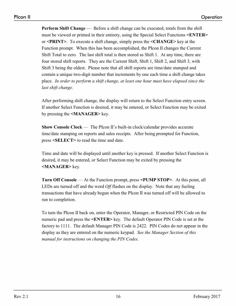
Perform Shift Change — Before a shift change can be executed, totals from the shift
must be viewed or printed in their entirety, using the Special Select Functions <ENTER>
or <PRINT>. To execute a shift change, simply press the <CHANGE> key at the
Function prompt. When this has been accomplished, the PIcon II changes the Current
Shift Total to zero. The last shift total is then stored as Shift 1. At any time, there are
four stored shift reports. They are the Current Shift, Shift 1, Shift 2, and Shift 3, with
Shift 3 being the oldest. Please note that all shift reports are time/date stamped and
contain a unique two-digit number that increments by one each time a shift change takes
place. In order to perform a shift change, at least one hour must have elapsed since the
last shift change.
After performing shift change, the display will return to the Select Function entry screen.
If another Select Function is desired, it may be entered, or Select Function may be exited
by pressing the <MANAGER> key.
Show Console Clock — The PIcon II’s built-in clock/calendar provides accurate
time/date stamping on reports and sales receipts. After being prompted for Function,
press <SELECT> to read the time and date.
Time and date will be displayed until another key is pressed. If another Select Function is
desired, it may be entered, or Select Function may be exited by pressing the
<MANAGER> key.
Turn Off Console — At the Function prompt, press <PUMP STOP>. At this point, all
LEDs are turned off and the word Off flashes on the display. Note that any fueling
transactions that have already begun when the PIcon II was turned off will be allowed to
run to completion.
To turn the PIcon II back on, enter the Operator, Manager, or Restricted PIN Code on the
numeric pad and press the <ENTER> key. The default Operator PIN Code is set at the
factory to 1111. The default Manager PIN Code is 2422. PIN Codes do not appear in the
display as they are entered on the numeric keypad. See the Manager Section of this
manual for instructions on changing the PIN Codes.
Rev 2.1 February 201716

PIcon II Operation
Operator AccessTo access PIcon II program and report features, a sequence utilizing a valid PIN Code must first
be entered. Access is divided into two categories — Manager and Operator. The manager, using
a Manager PIN Code, has access to Reports and Manager Modes. Reports functions (Modes
OPR 1 and OPR 2) are available to both the operator and the manager.
Access to Reports functions is accomplished through the entry of a valid Operator PIN Code.
First, press the <MANAGER> key. A prompt on the display will ask for your PIN Code. Enter
your Operator PIN Code on the numeric keypad. This number, with a maximum of four digits, is
stored in the PIcon II. Its purpose is to limit access to PIcon II report data. The number 1111 is
the factory default value for the Operator PIN Code. Next, press the <ENTER> key. OPR 0
will appear in the display, prompting for the desired mode number to be entered on the numeric
keypad. Press <ENTER> again to generate the requested Reports function sequence. Press the
<MANAGER> key to exit current mode.
Operator Accessible Modes
OPR 1 — Read Reports (Refer to Reports Section, Read Reports)
OPR 2 — Print Reports (Refer to Reports Section, Print Reports)
Rev 2.1 February 201717

PIcon II Manager
MANAGER
Manager AccessBefore initializing Manager Mode, restricted programming must be completed. To access PIcon
II Reports and Programming features, a sequence utilizing a valid PIN Code must first be
entered. Access is divided into two categories — Manager and Operator. The manager, using a
Manager PIN Code, has access to Reports and Manager Modes. Reports functions (Modes OPR
1 and OPR 2) are also available to the operator, who uses an Operator PIN Code. Manager
Access is described below.
Entry of the correct Manager PIN Code allows access to all Reports and Manager Modes. First,
press <MANAGER> key. The display will prompt for a PIN Code. Enter this PIN Code on the
numeric keypad. (This number, with a maximum of four digits, is stored in the PIcon II. Its
purpose is to limit access to PIcon II program and report data. The number 2422 is the factory
default value for the Manager PIN Code.) Next, press the <ENTER> key. MGR 0 will appear
in the display, prompting entry of the desired function mode number on the numeric keypad.
(See mode descriptions.) Press <ENTER> again to generate the requested program & report
function sequence. At this point, if you wish to return to the operator mode, press the
<MANAGER> key to exit from all manager modes.
Manager Accessible Modes
MGR 1 — Program Product Price
MGR 2 — Read Reports (Refer to Reports Section, Read Reports)
MGR 3 — Print Reports (Refer to Reports Section, Print Reports)
MGR 4 — Clear Resettable Totals (Follows in Manager Section)
MGR 5 — Set Date and Time (Follows in Manager Section)
MGR 6 — Beeper Settings (Follows in Manager Section)
MGR 7 — Program Operator/Manager PIN Codes (Follows in Manager Section)
MGR 8 — Shift Report Setup (Follows in Manager Section)
MGR 9 — Set Auto Receipts (Follows in Manager Section)
MGR 10 — Set Default MOP (Follows in Manager Section)
Rev 2.1 February 201718

PIcon II Manager
Manager Mode MGR 1 — Program Product Price
To enter this mode from the mode number prompt, MGR 0, enter <1> on the keypad and
press <ENTER>. Prices may be set for the following:
Cash PPU — To set the Cash PPU for a product, enter the desired PPU on the numeric
keypad and press the <CASH PAID> key. The three decimal places are assumed.
Credit PPU — To set the Credit PPU for a product, enter the desired PPU on the
numeric keypad and press the <CREDIT PAID> key. The three decimal places are
assumed.
As the Cash and Credit PPUs are entered, numeric key errors may be erased by pressing
the <CLEAR> key . The value will appear in the display. Note: Both Cash and Credit
prices must be programmed for each product — even if prices are the same. The
<SELECT> key moves to the next product.
To exit Mode 1, press the <MANAGER> key. MGR 0, the mode entry prompt, will
appear on the display. To return to operator mode, press the <MANAGER> key again.
Manager Mode MGR 2 — Read Reports (Refer to Reports Section, Read Reports)
Manager Mode MGR 3 — Print Reports (Refer to Reports Section, Print Reports)
Manager Mode MGR 4 — Clear Resettable Totals
MGR 4 is used to reset resettable totals by clearing them to zero. To enter this mode
from the mode number prompt, MGR 0, enter <4> on the keypad and press <ENTER>.
Rev 2.1 February 201719

PIcon II Manager
The display will show Press CLEAR. To zero all resettable totals, proceed by pressing
<CLEAR>. To exit Mode 4, press the <MANAGER> key. MGR 0, the mode entry
prompt, will appear on the display. To return to operator mode, press the <MANAGER>
key again.
Manager Mode MGR 5 — Set Date and Time
MGR 5 allows the setting of time, date and year. To enter MGR 5 from the MGR 0 mode
number prompt, press <5> and press <ENTER>. Date and time may now be set.
Time — The time previously set in the PIcon II will be displayed. To change the
hour, enter the hours on the numeric keypad in 24 hour format. New hours will
appear in the display as it is entered. Press <ENTER> . The cursor will proceed
to minutes. To change the minutes, enter the minutes on the keypad in two-digit
format. Minutes will be displayed as entered. Seconds are not entered and will be
automatically set as 00. Press <ENTER> again to proceed to set the date.
Date — Date already set in PIcon II will be displayed. Following the cursor,
change the month by entering the new month on the numeric keypad in two-digit
format. The new month will appear in the display as it is entered. Press
<ENTER> and the cursor will proceed to day of the month. To change the day of
the month, enter the day on the keypad in two-digit format. Day of the month will
be displayed as entered. Press <ENTER> again to proceed to set the year. The
year already set in the PIcon II will be displayed and may be changed by entering
the new year on the numeric keypad in four digits. The new year will display as it
is being entered. Press <ENTER> and the year will be updated.
To exit MGR 5, press the <MANAGER> key. MGR 0, the mode entry prompt,
will appear on the display. To return to operator mode, press the <MANAGER>
key again.
Rev 2.1 February 201720

PIcon II Manager
Manager Mode MGR 6 — Beeper Settings
Mode MGR 6 is used to select beeper volume, as well as single or continuous beeps for
Handle, Collect and Drive-Away. (Note: The console defaults to a single beep unless set
otherwise.) To enter MGR 6 from MGR 0, the mode number prompt, enter <6> on the
numeric keypad and press <ENTER>.
Beeper Volume — The first selection of MGR 6 is for Beeper Volume. Using
the <A/B> key, toggle among High/Low/Off. Pressing <ENTER> cycles to the
next selection.
Handle/Call for Service — The second display prompt is for selection of the
style of beep associated with a Handle/Call for Service. To change the style of
beep, press the <A/B> key and toggle between Single and Continuous. To
proceed to the next option setting, press <ENTER>.
Collect — The third display prompts for selection of the style of beep associated
with a Collect condition. To change the style of beep, press the <A/B> key and
toggle between single and continuous. To proceed to the next option setting,
press the <ENTER> key.
Drive-Away — The fourth display now prompts for selection of the style of beep
associated with a Drive-Away condition. To change the style of beep, press the
<A/B> key and toggle between Single and Continuous.
Rev 2.1 February 201721

PIcon II Manager
To exit MGR 6, press the <MANAGER> key. MGR 0, the mode entry prompt, will
appear on the display. To return to operator mode, press the <MANAGER> key again.
Manager Mode MGR 7/Program Mode PGM 13 — Program Operator/Manager PIN Codes
MGR 7 is used to change the PIN codes necessary to access Manager and Operator
functions. To enter this mode from the mode number prompt, MGR 0, enter <7> on the
keypad and press <ENTER>.
Warning: Care should be observed when using this mode. If the PIN Code is altered, be
sure to make note of the new PIN Code and save in a safe location.
Operator PIN Codes — The display will show the existing Operator PIN Code
under Operator PIN. (The default Operator PIN Code is 1111.) To change the
code, enter the new number (up to 4 digits) on the numeric keypad and press
<ENTER>. To proceed to program Manager PIN Codes, press <ENTER>.
Manager PIN Codes — Under Manager PIN, the existing Manager PIN Code
will be displayed. (The default Manager PIN Code is 2422.) To change the code,
enter the new number (up to 4 digits) on the numeric keypad and press <ENTER>
— taking you back to Operator PIN Codes.
To exit MGR 7, press the <MANAGER> key. MGR 0, the mode entry prompt, will
appear on the display. To return to operator mode, press the <MANAGER> key again.
Rev 2.1 February 201722

PIcon II Manager
Manager Mode MGR 8 — Shift Report Setup
The operator Shift Report Setup Mode configures which totals are to be printed on an
operator Shift Report. To choose the totals to be included, simply toggle between Yes
and No by using the <A/B> key. The <SELECT> key cycles to the next option to be
programmed. Totals which may be selected (or declined) for inclusion on the Operator
Shift Report are:
By Pump — default is Yes
Resettable — default is No
Non-resettable — default is No
Polled (read from dispenser) — default is Yes
Grand Resettable — default is Yes
Grand Non-reset. — default is Yes
To exit MGR 8, press the <MANAGER> key. MGR 0, the mode entry prompt, will
appear on the display. To return to operator mode, press the <MANAGER> key again.
Rev 2.1 February 201723

PIcon II Manager
Manager Mode MGR 9 — Set Auto Receipts
MGR 9 automatically prints a sales receipt if in full service. The <A/B> key toggles
between Off and Full Service.
To exit MGR 9, press the <MANAGER> key. MGR 0, the mode entry prompt, will
appear on the display. To return to operator mode, press the <MANAGER> key again.
Manager Mode MGR 10 — Set Default MOP
MGR 10 sets the PIcon II into a default Method of Payment (MOP) mode of
None/Cash/Credit. At the end of each transaction, the PIcon II returns to the selected
default MOP.
To exit MGR 10, press the <MANAGER> key. MGR 0, the mode entry prompt, will
appear on the display. To return to operator mode, press the <MANAGER> key again.
Rev 2.1 February 201724
PIcon II Reports
REPORTS
Read Reports
The purpose of Read Reports is to select and display totals reports for viewing. This function is
available to both manager and operator, but is accessed differently, as described below.
Operator Mode OPR 1/Manager Mode MGR 2 — Read Reports
Operator Mode OPR 1 is accessed from the OPR 0 mode number prompt, by entering
<1> on the keypad. Then press <ENTER>.
Manager Mode MGR 2 is accessed from MGR 0 mode number prompt, by entering <2>
on the keypad. Then press <ENTER>.
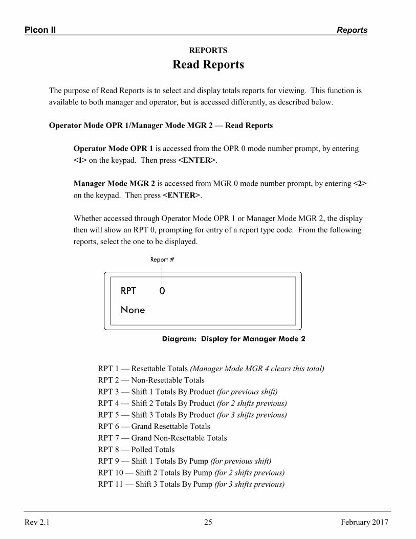
Whether accessed through Operator Mode OPR 1 or Manager Mode MGR 2, the display
then will show an RPT 0, prompting for entry of a report type code. From the following
reports, select the one to be displayed.
RPT 1 — Resettable Totals (Manager Mode MGR 4 clears this total)
RPT 2 — Non-Resettable Totals
RPT 3 — Shift 1 Totals By Product (for previous shift)
RPT 4 — Shift 2 Totals By Product (for 2 shifts previous)
RPT 5 — Shift 3 Totals By Product (for 3 shifts previous)
RPT 6 — Grand Resettable Totals
RPT 7 — Grand Non-Resettable Totals
RPT 8 — Polled Totals
RPT 9 — Shift 1 Totals By Pump (for previous shift)
RPT 10 — Shift 2 Totals By Pump (for 2 shifts previous)
RPT 11 — Shift 3 Totals By Pump (for 3 shifts previous)
Rev 2.1 February 201725

PIcon II Reports
Select the report number and enter it on the PIcon II keypad, then press <ENTER>. The
beginning data for the report is shown in the display. Use the following keys to scroll
through the report.
<VOLUME> Shows Volume Total
<CASH PAID> Shows Cash Total
<CREDIT PAID> Shows Credit Total
<1> Shows Low Feed Stock Total (totals for meter 1 by
dispenser)
<2> Shows High Feed Stock Total (totals for meter 2 by dispenser)
<ENTER> Next Product or Hose
<PUMP # KEY> Select Pump
To exit OPR 1/MGR 2, press the <MANAGER> key. MGR 0, the mode entry prompt, will
appear on the display. To return to operator mode, press the <MANAGER> key again.
Rev 2.1 February 201726

PIcon II Reports
Print Reports
The purpose of Print Reports is to generate and print totals reports if a printer is attached to the
PIcon II, as well as to program the print header. If no printer is attached, “Paper Out” will appear
on the PIcon II display. This function is available to both manager and operator, but is accessed
differently, as described below.
Operator Mode OPR 2/Manager Mode M 3 — Print Reports
Operator Mode OPR 2 is accessed from the OPR 0 mode number prompt, by entering <2>
on the keypad. Then press <ENTER>.
Manager Mode MGR 3 is accessed from MGR 0 mode number prompt, by entering <3>
on the keypad. Then press <ENTER>.
Whether accessed through Operator Mode OPR 2 or Manager Mode MGR 3, the display
then will show PRN 0, prompting for entry of a report code number. From the following
reports, select the one to be printed.
PRN 1 — Resettable Totals
PRN 2 — Non-Resettable Totals
PRN 3 — Shift 1 Totals By Product (for previous shift)
PRN 4 — Shift 2 Totals By Product (for 2 shifts previous)
PRN 5 — Shift 3 Totals By Product (for 3 shifts previous)
PRN 6 — Grand Resettable Totals
PRN 7 — Grand Non-Resettable Totals
PRN 8 — Polled Totals
PRN 9 — Shift 1 Totals By Pump (for previous shift)
Rev 2.1 February 201727

PIcon II Reports
PRN 10 — Shift 2 Totals By Pump (for 2 shifts previous)
PRN 11 — Shift 3 Totals By Pump (for 3 shifts previous)
PRN 12 — Print Program Settings
PRN 13 — Print Error Queue
PRN 14 — Program Print Header
PRN 15 — Print Interrupt Log
PRN 16 — Print Application Log
PRN 17 — Print Debug Info
PRN 18 — Print Diagnostics Report
Select the report number of the report to be printed and enter it on the PIcon II keypad, then
press <ENTER>. The chosen report will be printed and the display will return to PRN 0.
To exit OPR 2/MGR 3, press the <MANAGER> key. MGR 0, the mode entry prompt, will
appear on the display. To return to operator mode, press the <MANAGER> key again.
PRN 14 – Print Header – Initiate programming of Print Header by pressing <14>
from the opening print screen, PRN 0. The display will show the beginning
information for the print header. If the header has not already been programmed or
has been cleared, the cursor will prompt for the first character entry. Refer to Table:
Print Header Character Codes at the end of this section for a numeric code which
represents the characters available for your use on the printer header. Determine
the character you wish to place in the first position of the header and look up the
numeric code. Enter this numeric code on the keypad and press <ENTER>. The
character will appear on the display, and has been saved in memory. For each
subsequent character, follow the same sequence.
There are two special numeric codes for the header: <10> indicates a new line in the
header; <01> is the code for end of header. Enter the new line code at the point
where the printer should cease printing on the current line and go to the beginning of
the next line. The end of header code is entered after the entire header is entered and
will tell the PIcon II that no more characters are needed in the header.
Special editing features are available for use under Print Header:
<ENTER> without entering a numeric code — Display cursor will increment to next
character in the header.
<SELECT> without entering a numeric code — Display cursor will go back one
character in the header.
Rev 2.1 February 201728

PIcon II Reports
<CHANGE> without entering a numeric code — Entire print header will be cleared.
<PRINT> without entering a numeric code — Printer will print the header that is
programmed.
<MANAGER> — Exit Print Header programming.
To exit Mode MGR 3, press the <MANAGER> key. MGR 0, the mode entry prompt, will
appear on the display. To return to operator mode, press the <MANAGER> key again.
Print Header Character Codes01 = end of header 10 = new line
0 48 F 70 U 85 j 106 y 121 - 45 < 96
1 49 G 71 V 86 k 107 z 122 . 46 { 123
2 50 H 72 W 87 l 108 space
32 / 47 | 124
3 51 I 73 X 88 m 109 ! 33 : 58 } 125
4 52 J 74 Y 89 n 110 " 34 ; 59 ~ 126
5 53 K 75 Z 90 o 111 # 35 < 60
6 54 L 76 a 97 p 112 $ 36 = 61
7 55 M 77 b 98 q 113 % 37 > 62
8 56 N 78 c 99 r 114 & 38 ? 63
9 57 O 79 d 100 s 115 ' 39 @ 64
A 65 P 80 e 101 t 116 ( 40 [ 91
B 66 Q 81 f 102 u 117 ) 41 \ 92
C 67 R 82 g 103 v 118 * 42 ] 93
D 68 S 83 h 104 w 119 + 43 ^ 94
E 69 T 84 i 105 x 120 , 44 _ 95
Table: Print Header Character Codes
Rev 2.1 February 201729

PIcon II Programming
PROGRAMMING
To avoid accidental mistakes and clearing of previous programming, Program Modes may only
be accessed by using Restricted PIN Code. For basic startup, press <SELECT> twice and check
to ensure that the date is correct. If incorrect, change date as explained in Manager Mode
Section. If date is correct, calculate restricted code by multiplying the current month, times the
day, plus the year. For example, if the date were December 10, 2000, the restricted code would
be calculated as follows:
12 X 10 + 2000 = 2120 Restricted access code would be 2120.
When Programming Mode is entered, PGM 0 will appear on the display, prompting for a
Program Mode # to be entered.
Choose among the following and enter corresponding number at the Program Mode prompt.
PGM 1 — Pump Type
PGM 2 — Pump Configuration
PGM 3 — Product Name Assignment
PGM 4 — Set Dollar/Volume Default
PGM 5 — Set Dollar/Cash or Credit
PGM 6 — Set Gallon/Litre Receipt
PGM 7 — Handle for Authorization
PGM 8 — Set $/V/PPU Decimals
PGM 9 — Set Language
PGM 10 — Stacked Sales (Y/N)
PGM 11 — ATG Activation
PGM 12 — Clear Event Log
PGM 13 — Program Operator/Manager PIN Codes
PGM 14 — Drive Away Activation
PGM 15 — Program Tax Percentage
Rev 2.1 February 201730
PIcon II Programming
PGM 16 — Pump Interface (PIPORT/RS422)
PGM 60 — Pump Specific Settings
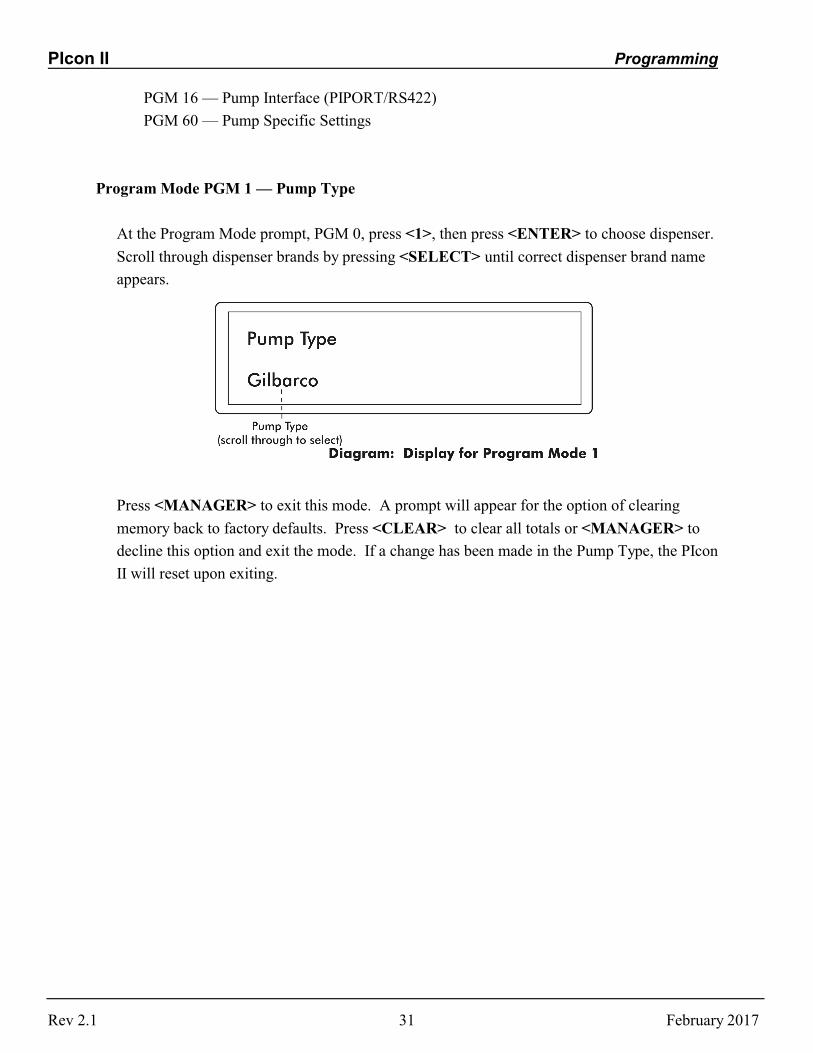
Program Mode PGM 1 — Pump Type
At the Program Mode prompt, PGM 0, press <1>, then press <ENTER> to choose dispenser.
Scroll through dispenser brands by pressing <SELECT> until correct dispenser brand name
appears.
Press <MANAGER> to exit this mode. A prompt will appear for the option of clearing
memory back to factory defaults. Press <CLEAR> to clear all totals or <MANAGER> to
decline this option and exit the mode. If a change has been made in the Pump Type, the PIcon
II will reset upon exiting.
Rev 2.1 February 201731
PIcon II Programming
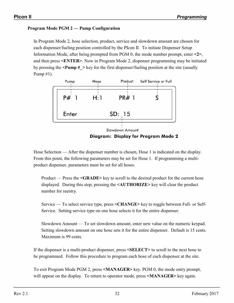
Program Mode PGM 2 — Pump Configuration
In Program Mode 2, hose selection, product, service and slowdown amount are chosen for
each dispenser/fueling position controlled by the PIcon II. To initiate Dispenser Setup
Information Mode, after being prompted from PGM 0, the mode number prompt, enter <2>,
and then press <ENTER>. Now in Program Mode 2, dispenser programming may be initiated
by pressing the <Pump #_> key for the first dispenser/fueling position at the site (usually
Pump #1).
Hose Selection — After the dispenser number is chosen, Hose 1 is indicated on the display.
From this point, the following parameters may be set for Hose 1. If programming a multi-
product dispenser, parameters must be set for all hoses.
Product — Press the <GRADE> key to scroll to the desired product for the current hose
displayed. During this step, pressing the <AUTHORIZE> key will clear the product
number for reentry.
Service — To select service type, press <CHANGE> key to toggle between Full- or Self-
Service. Setting service type on one hose selects it for the entire dispenser.
Slowdown Amount — To set slowdown amount, enter new value on the numeric keypad.
Setting slowdown amount on one hose sets it for the entire dispenser. Default is 15 cents.
Maximum is 99 cents.
If the dispenser is a multi-product dispenser, press <SELECT> to scroll to the next hose to
be programmed. Follow this procedure to program each hose of each dispenser at the site.
To exit Program Mode PGM 2, press <MANAGER> key. PGM 0, the mode entry prompt,
will appear on the display. To return to operator mode, press <MANAGER> key again.
Rev 2.1 February 201732
PIcon II Programming
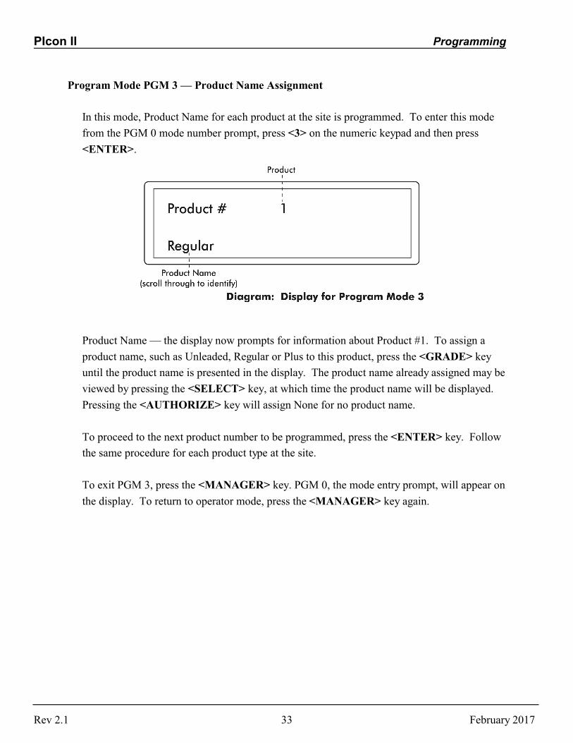
Program Mode PGM 3 — Product Name Assignment
In this mode, Product Name for each product at the site is programmed. To enter this mode
from the PGM 0 mode number prompt, press <3> on the numeric keypad and then press
<ENTER>.
Product Name — the display now prompts for information about Product #1. To assign a
product name, such as Unleaded, Regular or Plus to this product, press the <GRADE> key
until the product name is presented in the display. The product name already assigned may be
viewed by pressing the <SELECT> key, at which time the product name will be displayed.
Pressing the <AUTHORIZE> key will assign None for no product name.
To proceed to the next product number to be programmed, press the <ENTER> key. Follow
the same procedure for each product type at the site.
To exit PGM 3, press the <MANAGER> key. PGM 0, the mode entry prompt, will appear on
the display. To return to operator mode, press the <MANAGER> key again.
Rev 2.1 February 201733
PIcon II Programming
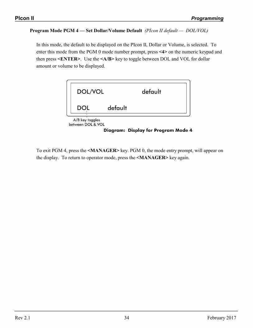
Program Mode PGM 4 — Set Dollar/Volume Default (PIcon II default — DOL/VOL)
In this mode, the default to be displayed on the PIcon II, Dollar or Volume, is selected. To
enter this mode from the PGM 0 mode number prompt, press <4> on the numeric keypad and
then press <ENTER>. Use the <A/B> key to toggle between DOL and VOL for dollar
amount or volume to be displayed.
To exit PGM 4, press the <MANAGER> key. PGM 0, the mode entry prompt, will appear on
the display. To return to operator mode, press the <MANAGER> key again.
Rev 2.1 February 201734
PIcon II Programming
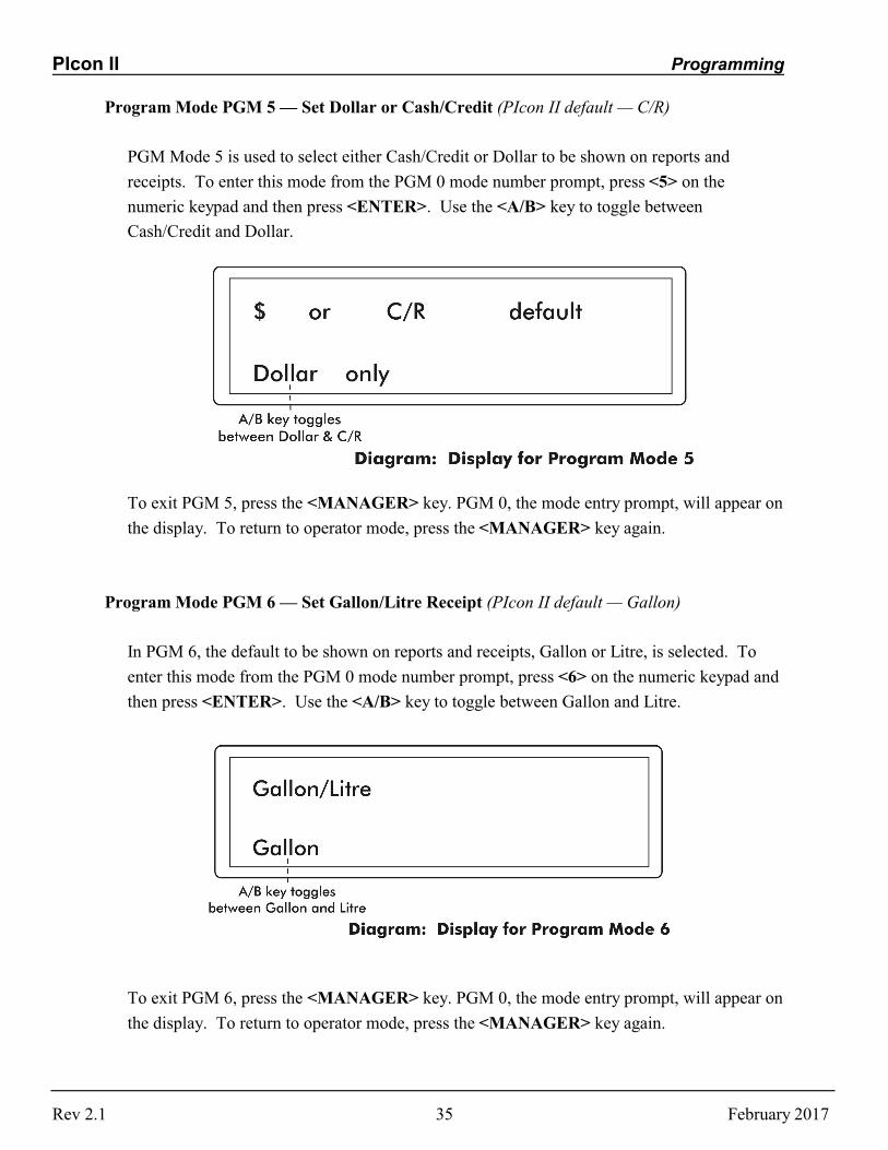
Program Mode PGM 5 — Set Dollar or Cash/Credit (PIcon II default — C/R)
PGM Mode 5 is used to select either Cash/Credit or Dollar to be shown on reports and
receipts. To enter this mode from the PGM 0 mode number prompt, press <5> on the
numeric keypad and then press <ENTER>. Use the <A/B> key to toggle between
Cash/Credit and Dollar.
To exit PGM 5, press the <MANAGER> key. PGM 0, the mode entry prompt, will appear on
the display. To return to operator mode, press the <MANAGER> key again.
Program Mode PGM 6 — Set Gallon/Litre Receipt (PIcon II default — Gallon)
In PGM 6, the default to be shown on reports and receipts, Gallon or Litre, is selected. To
enter this mode from the PGM 0 mode number prompt, press <6> on the numeric keypad and
then press <ENTER>. Use the <A/B> key to toggle between Gallon and Litre.
To exit PGM 6, press the <MANAGER> key. PGM 0, the mode entry prompt, will appear on
the display. To return to operator mode, press the <MANAGER> key again.
Rev 2.1 February 201735

PIcon II Programming
Program Mode PGM 7 — Handle for Authorization (PIcon II default — Yes)
PGM 7 determines whether the PIcon II must acknowledge the handle request before
authorization is sent to the pump. To enter this mode from the PGM 0 mode number prompt,
press <7> on the numeric keypad and then press <ENTER>. Use the <A/B> key to toggle
between Yes and No.
To exit Program Mode 7, press the <MANAGER> key. PGM 0, the mode entry prompt, will
appear on the display. To return to operator mode, press the <MANAGER> key again.
Program Mode PGM 8 — Set Dollar/Volume/PPU Decimals (PIcon II default for Dollar — 2;
default for Volume – 3; default for PPU – 3)
Program Mode 8 selection determines the number of decimals to be used in the Dollar,
Volume and Price Per Unit (PPU) that will be shown on the PIcon II display and receipts. To
enter this mode from the PGM 0 mode number prompt, press <8> on the numeric keypad and
then press <ENTER>. First, the Dollar selection appears. Use the <A/B> key to toggle
among 0, 1, 2 or 3. After selection is made, press <ENTER> to proceed to program Volume
and PPU in the same manner until programming of decimals is complete.
Rev 2.1 February 201736

PIcon II Programming
To exit Program Mode 8, press the <MANAGER> key. PGM 0, the mode entry prompt, will
appear on the display. To return to operator mode, press the <MANAGER> key again.
Program Mode PGM 9 — Set Language (PIcon II default – English)
PGM 9 is used to select the language to appear on display and printed reports. To enter this
mode from the PGM 0 mode number prompt, press <9> on the numeric keypad and then
press <ENTER>. Use the <A/B> key to toggle among supported languages.
To exit Program Mode 9, press the <MANAGER> key. PGM 0, the mode entry prompt, will
appear on the display. To return to operator mode, press the <MANAGER> key again.
Program Mode PGM 10 — Stacked Sales (Yes/No) (PIcon II default — Yes)
Program Mode 10 enables or disables stacked sales. To enter this mode from the PGM 0
mode number prompt, press <10> on the numeric keypad and then press <ENTER>. Use the
<A/B> key to toggle between Yes and No.
To exit Program Mode 10, press the <MANAGER> key. PGM 0, the mode entry prompt,
will appear on the display. To return to operator mode, press the <MANAGER> key again.
Rev 2.1 February 201737

PIcon II Programming
Program Mode PGM 11 — ATG Activation (PIcon II default — No)
Program Mode 11 enables or disables the connection between the PIcon II and an auto tank
guage (ATG), if one is available. When enabled, sales information will be transferred to the
ATG in EMC/BIR G-site format. To enter this mode from the PGM 0 mode number prompt,
press <11> on the numeric keypad and then press <ENTER>. Use the <A/B> key to toggle
between Yes and No.
To exit Program Mode 11, press the <MANAGER> key. PGM 0, the mode entry prompt,
will appear on the display. To return to operator mode, press the <MANAGER> key again.
Program Mode PGM 12 — Clear Event Log
Program Mode 12 clears the Application Log and the Interrupt Log. To enter this mode from
the PGM 0 mode number prompt, press <12> on the numeric keypad and then press
<ENTER>. The Event logs will be cleared and the display will return to PGM 0. To return to
operator mode, press the <MANAGER> key.
Program Mode PGM 13/Manager Mode MGR 7 — Program Operator/Manager PIN Codes
PGM 13 is used to change the PIN codes necessary to access Manager and Operator functions.
To enter this mode from the mode number prompt, PGM 0, enter <13> on the keypad and press
<ENTER>.
Warning: Care should be observed when using this mode. If the PIN Code is altered, be sure
to make note of the new PIN Code and save in a safe location.
Rev 2.1 February 201738

PIcon II Programming
Operator PIN Codes — The display will show the existing Operator PIN Code under
Operator PIN. (The default Operator PIN code is 1111.) To change the code, enter the
new number (up to 4 digits) on the numeric keypad and press <ENTER>. To proceed to
program Manager PIN Codes, press <ENTER>.
Manager PIN Codes — Under Manager PIN, the existing Manager PIN Code will be
displayed. (The default Manager PIN Code is 2422.) To change the code, enter the new
number (up to 4 digits) on the numeric keypad and press <ENTER> — taking you back
to Operator PIN Codes.
To exit PGM 13, press the <MANAGER> key. PGM 0, the mode entry prompt, will appear on
the display. To return to operator mode, press the <MANAGER> key again.
Program Mode PGM 14 — Drive Away Activation (PIcon II default — On)
Program Mode 14 enables or disables the Drive Away function. When disabled, the console
will not alert when the handle is off-hook and flow has stopped for more than 7 seconds. To
enter this mode from the PGM 0 mode number prompt, press <14> on the numeric keypad and
then press <ENTER>. Use the <A/B> key to toggle between On and Off.
To exit Program Mode 14, press the <MANAGER> key. PGM 0, the mode entry prompt, will
appear on the display. To return to operator mode, press the <MANAGER> key again.
Rev 2.1 February 201739
PIcon II Programming
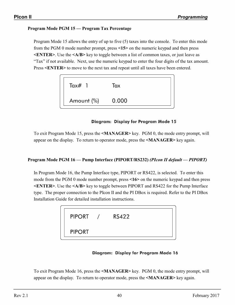
Program Mode PGM 15 — Program Tax Percentage
Program Mode 15 allows the entry of up to five (5) taxes into the console. To enter this mode
from the PGM 0 mode number prompt, press <15> on the numeric keypad and then press
<ENTER>. Use the <A/B> key to toggle between a list of common taxes, or just leave as
“Tax” if not available. Next, use the numeric keypad to enter the four digits of the tax amount.
Press <ENTER> to move to the next tax and repeat until all taxes have been entered.
To exit Program Mode 15, press the <MANAGER> key. PGM 0, the mode entry prompt, will
appear on the display. To return to operator mode, press the <MANAGER> key again.
Program Mode PGM 16 — Pump Interface (PIPORT/RS232) (PIcon II default — PIPORT)
In Program Mode 16, the Pump Interface type, PIPORT or RS422, is selected. To enter this
mode from the PGM 0 mode number prompt, press <16> on the numeric keypad and then press
<ENTER>. Use the <A/B> key to toggle between PIPORT and RS422 for the Pump Interface
type. The proper connection to the PIcon II and the PI DBox is required. Refer to the PI DBox
Installation Guide for detailed installation instructions.
To exit Program Mode 16, press the <MANAGER> key. PGM 0, the mode entry prompt, will
appear on the display. To return to operator mode, press the <MANAGER> key again.
Rev 2.1 February 201740

PIcon II Programming
Program Mode PGM 60 — Pump Specific Settings (Not available for all dispenser brands.)
Allows configuration of advanced brand-specific options. For assistance with this program
mode, contact Dealer.
Note: Program Mode 1, Pump Type, must be set before continuing with this program mode.
Program Mode 60 allows the configuring of advanced brand-specific options of the PIcon II.
See Table: Dispenser-Specific Configurations, which follows. Options will vary among the
different dispenser brands. To enter this mode, press <60> on the numeric keypad and then
press <ENTER>. If settings are available for the selected dispenser type, the options will be
displayed. Some dispensers have “global” settings which affect all 16 dispensers controlled by
the PIcon II. If this option is available, the top line of the display will not show P01. Using the
<A/B> key, toggle among the choices for each option. Press <ENTER> to advance to the next
option.
When global settings have been configured (or if global settings are not available), press
<PUMP 1> to begin configuration of individual fueling positions. Using the <A/B> key,
toggle among the choices for each option. Press <ENTER> to advance to the next option.
When the first position is configured, press <PUMP 2> to configure the next dispenser.
Continue until all dispensers are configured.
The <SELECT> key will toggle from global settings to individual pump settings.
To exit Program Mode 60, press the <MANAGER> key. PGM 0, the mode entry prompt, will
appear on the display. To return to operator mode, press the <MANAGER> key again.
Rev 2.1 February 201741

PIcon II Programming
Table: Dispenser-Specific Configurations
Brand Available Settings (Options)
Bennett Number of PPU Displays (1 or 2)Model Type (all model types available)
Deer Number of PPU Displays (1 or 2)Volume Decimal Digits (2 or 3)Preset Digits (4 or 6)PPU Decimal Places (0, 1, 2, or 3)
Gilbarco Communication Speed (Modular or Legacy) [Channel Setting]Special Function Commands (yes or no)Hose Test (yes or no)Dollar Decimal Point (0, 1, or 2)Volume Decimal Point (2 or 3)PPU Decimal Point (0, 1, 2, or 3)
Kraus Pump Head Type (Kraus or MTI)PPU Decimal Point (0, 1, 2, or 3)Volume Decimal Point (0, 1, 2, or 3)Dollar Decimal Point (0, 1, 2)
Mechanical Handle for Authorization (yes or no)
PMC Preset Type (Volume or Dollar)
Tatsuno Dollar Decimal Point (0, 1, or 2)Volume Decimal Point (0, 1, 2, or 3)PPU Decimal Point (0, 1, 2, or 3)
Tokheim Unit of Measure (Litres or Gallons)Volume Decimal Point (2 or 3)Model Type (all model types available)Blend Ratio (numeric entry for each hose)
Wayne BCD (enabled or disabled)MOP Switches (yes or no)Blender with Single Product (3+1) (yes or no)Number of PPU Displays (1 or 2)Dollar Decimal Point (0, 1, or 2) Volume Decimal Point (2 or 3)PPU Decimal Point (0, 1, 2, or 3)
Rev 2.1 February 201742

PIcon II Diagnostics
DIAGNOSTICS
PIcon II Internal DiagnosticsRefer to our web site, www.pie-corp.com for more comprehensive diagnostics.
The PIcon II has on-board diagnostics which are helpful in solving problems encountered in thefield. Below are some standard diagnostic functions, which are described later in this section:
• Show Dispenser Information • Display Version Information • Download Print Header • Configure Dispenser Settings
To access diagnostics, a computer running a terminal emulation software such as Hyperterm forWindows is required. Note: A standard A to B USB cable is used to connect the terminal device tothe diagnostic port, not a null modem cable. See Diagram: PIcon II Port Layout for connectorlocations. The diagnostic port is a serial port with the following connection parameters.
• Baud Rate 57,600 • Data Bits 8 • Parity None • Stop Bits 1 • Flow Control None
After connecting to the diagnostics port and starting the terminal emulation program, power up thePIcon II. A menu will appear, displaying the various diagnostic functions available. To select afunction, type the letter shown in the menu. Some features will prompt for additional information. Press the escape key to return to the previous menu level. Diagnostic procedures are described asfollows.
Rev 2.1 February 201743

PIcon II Diagnostics
Show Dispenser Information
This command displays the dispenser manufacturer’s pertinent information.
• Locate top diagnostic window displayed on terminal • Press D, Section Diagnostics • Press D, Pump Diagnostics • Press P, Pump Diagnostics • Select I, Show Pump Information • Press Escape key to return to previous level
Display Version Information
This command shows current PIcon II version.
• Locate top diagnostic window displayed on terminal • Press V, Show Version • Press any key to return to previous level
Download Print Header
The purpose of this command is to load a print header from a computer into the PIcon II. First, theprint header should be written in Notepad, using plain text — with no special formatting or tabs. (The appearance of centering, tabs, etc., must be accomplished through the use of additional hardspaces.) Then, print header may be downloaded by following this procedure:
• Locate top diagnostic window displayed on terminal
• Select D, Section Diagnostics
• Select P, Printer Diagnostics
• Select D, Download the Print Header.
• At the prompt, download may be aborted by pressing Escape key or continued by enteringany other key.
• If continuing download, C’s will continue to appear onscreen until the file to bedownloaded is selected. To select the print header file, go to Hyperterm’s toolbar andselect Transfer, then Send File. At the dialog box, browse for file to be downloaded. Select the file you have previously written for the print header. Under the Protocol sectionof the dialog box, select Xmodem. Press Send button. File will be downloaded. Whendownload is complete, program will automatically return to the previous prompt.
Rev 2.1 February 201744

PIcon II Diagnostics
Configure Pump
Dispenser specific options must be selected for some dispenser brands. Follow the sequence belowto configure these brands. If C, Configure Pump, does not appear after selecting Dispenser, thisparticular dispenser does not require configuration.
• Locate top diagnostic window displayed on terminal
• Select D, Section Diagnostics
• Select D, Pump Diagnostics
• Select P, Pump Diagnostics — If C, Configure Pump, does not appear at this point, thisparticular dispenser does not allow configuration.
• Select C, Configure Pump
• Select from options in menu window
Rev 2.1 February 201745

PIcon II Diagnostics
PIcon II Code Update
Contact PIE for upgrade files, which can be loaded via PIE’s STM32 Update Loader. This utility isavailable on our website: www.pie-corp.com.
Before beginning this procedure, close Hyperterm. Proceed with Code Update as follows:
• Connect the A to B USB cord between the computer and the PIcon II.
• Power down the PIcon II.
• Locate the Reset switch located in the small round hole beneath the power connection onback of the PIcon II.
• Using a small pointed object, such as a straightened paper clip, press and hold the Resetswitch for approximately five seconds while powering up.
• Open STM32 Update Loader and use these settings:
Port Name Com port # for Diagnostics
Baud Rate 256,000
Parity Even
Echo Disabled
Timeout(s) 10
• Select Next.
• Select Remove Protection to proceed.
Press and hold the Reset switch for approximately five seconds while selecting OKto reset the device.
• Screen will read, “Target is readable. Please click ‘Next’ to proceed. Select Next. ” Ifthis, or a similar message, does not appear, close program and go back to the first step.
• Verify that Target is STM32_XL_density_1024K. Select Next.
• Ensure that “Download to device” and “Global Erase” are selected. Select the file in“Download from file”. Leave all other options on this page as they are. Select Next.
• Close STM32 Update Loader when complete.
• Power cycle the PIcon II.
Rev 2.1 February 201746

PIcon II Diagnostics
PIcon II Basic Troubleshooting
Problem (Possible Cause) Possible Solution
Console Display flashing “OFF”C <SELECT>, <PUMP STOP> turns off
the console
Press 1111 <ENTER> (or one of the 2 PINCodes (Manager or Operator) programmed inthe console)
Red light flashing on a PumpC A sale is waiting to be paid outC It could be a prepay that did not go to
the limit (set for $20 and only pumped$15)
C It could be on the B side if StackedSales are turned on
<PUMP #><CASH PAID> (or <CREDIT PAID>)<CHANGE> (to refund change from a prepaythat didn’t go to the programmed limit)<A/B> (to switch to the B side sale)<CASH PAID> (or <CREDIT PAID>)<CHANGE>
Perform a Shift ChangeC Must View or Print the Current Shift
TotalsC Can only change shifts once an hour
<SELECT>C <PRINT> (If there is a printer connected)C <CHANGE> (display should briefly read
“Shift Changed”)orC <ENTER> (if there is no printer connected)
See Special Select Functions section fordetails on how to view report.
C <MANAGER> (exit viewing the report)C <CHANGE> (display should briefly read
“Shift Changed”)
Rev 2.1 February 201747