physics of proton therapy
TRANSCRIPT
PHYSICS OF PROTON THERAPY
Basit Athar, PhD DABRHampton University Proton Therapy Institute
1

PROTONS
•Protons are charged particles and directly interact with electrons.
•Their mass(Mp) is 938MeV/c2 in comparison Me = 0.511MeV/c2
•Knock-out electrons easily.
•Impart their energy to electrons thus to the medium.
•This energy imparted gives rise to the idea of DOSE.
2

CONCEPT OF DOSE Dose is a measure of the amount of energy deposited in a small volume as a result of the radiation - be that energy deposited locally, or brought to the point of interest by secondary radiation generated at some distance from the primary interaction.
Dose is defined as the energy deposited in a volume divided by its mass.
Dose is expressed in units of Gray (Gy) ~ 1Gy = Joule/kg
To understand this energy deposition, need to understand charge particle interaction with matter.
3

BASIC INTERACTIONS
•Energy Loss - Coulomb interactions with electrons. Defines the range and shape of dose profile along the beam line.
•Scattering - Coulomb interactions with target nuclei. Defines the shape of lateral profile.
•Nuclear Interactions - Inelastic nuclear interaction with target nuclei. Modifies the depth dose and lateral dose distribution.
4

WHY HEAVY CHARGED PARTICLES?
Heavy charged particle therapy can reduce the dose load “intergral dose” to normal tissues surrounding the tumor target volume by a factor of 2-3 (reduced “dose bath”)
5
80
100
120
140
160
180
200
0 5 10 15 20 25 30Depth (cm)
Dos
e (%
)
60
40
20
0
10 MV Photon
Proton SOBP (18cm)
Excessive dose
Tumor
WHY HEAVY CHARGED PARTICLES?
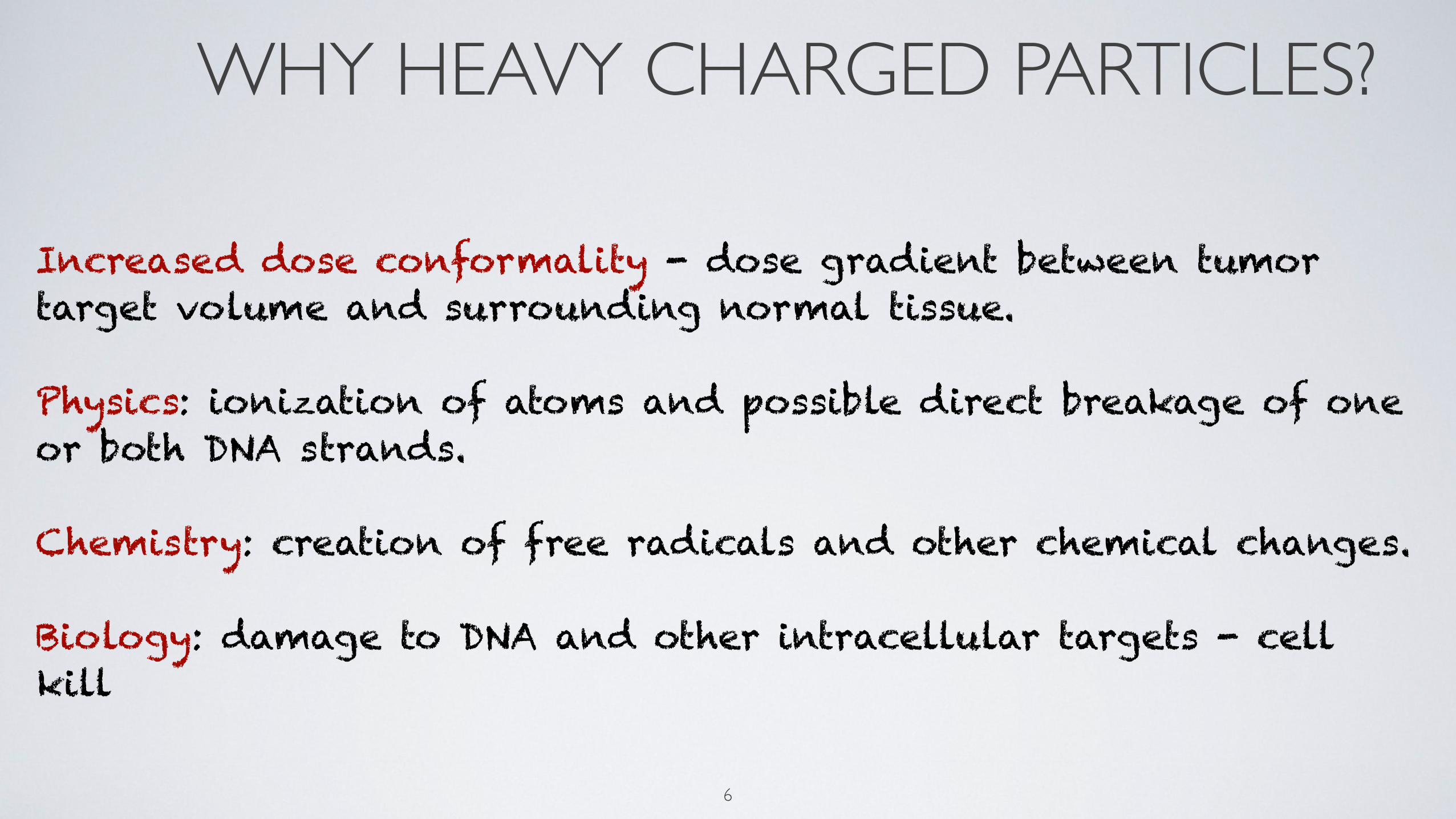
Increased dose conformality - dose gradient between tumor target volume and surrounding normal tissue.
Physics: ionization of atoms and possible direct breakage of one or both DNA strands.
Chemistry: creation of free radicals and other chemical changes.
Biology: damage to DNA and other intracellular targets - cell kill
6

ENERGY LOSS•Protons predominantly lose energy via coulomb interactions with the outer shell electrons of the target.
excitation and ionization of atoms
•loss per interaction is small - “continuously slowing down approximation” (CSDA) is valid.
•Range of secondary e+ is < 1mm - locally absorbed dose.
•Protons are ~2000 times heavier than electrons - no significant deflection.
•Energy loss is given by Bethe-Bloch equation.
7

ENERGY LOSS: BETHE-BLOCH EQUATION
http://physics.nist.gov/PhysRefData/Star/Text/PSTAR.html 8
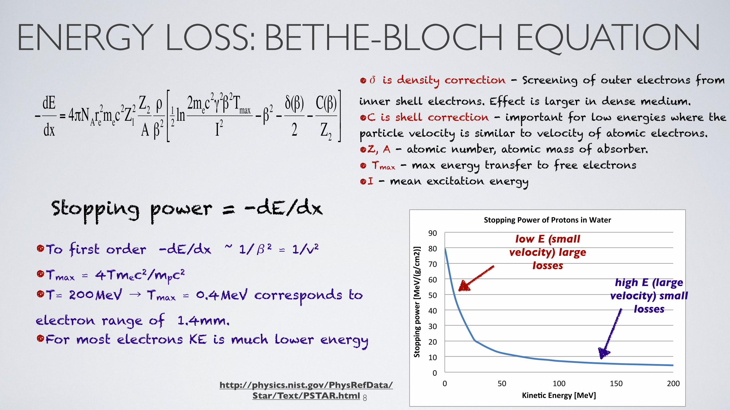
ENERGY LOSS: BETHE-BLOCH EQUATION•δ is density correction - Screening of outer electrons from
inner shell electrons. Effect is larger in dense medium.•C is shell correction - important for low energies where the particle velocity is similar to velocity of atomic electrons.•Z, A - atomic number, atomic mass of absorber.• Tmax - max energy transfer to free electrons•I - mean excitation energy
•To first order -dE/dx ~ 1/β2 ⋍ 1/v2
•Tmax ⋍ 4Tmec2/mpc2 •T⋍ 200MeV → Tmax ⋍ 0.4MeV corresponds to electron range of 1.4mm. •For most electrons KE is much lower energy
http://physics.nist.gov/PhysRefData/Star/Text/PSTAR.html
0"
10"
20"
30"
40"
50"
60"
70"
80"
90"
0" 50" 100" 150" 200"
Stop
ping(pow
er([M
eV/(g/cm
2)](
Kine7c(Energy([MeV](
Stopping(Power(of(Protons(in(Water(
high E (large velocity) small
losses
low E (small velocity) large
losses
8
Stopping power = -dE/dx
ENERGY LOSS: BRAGG PEAK
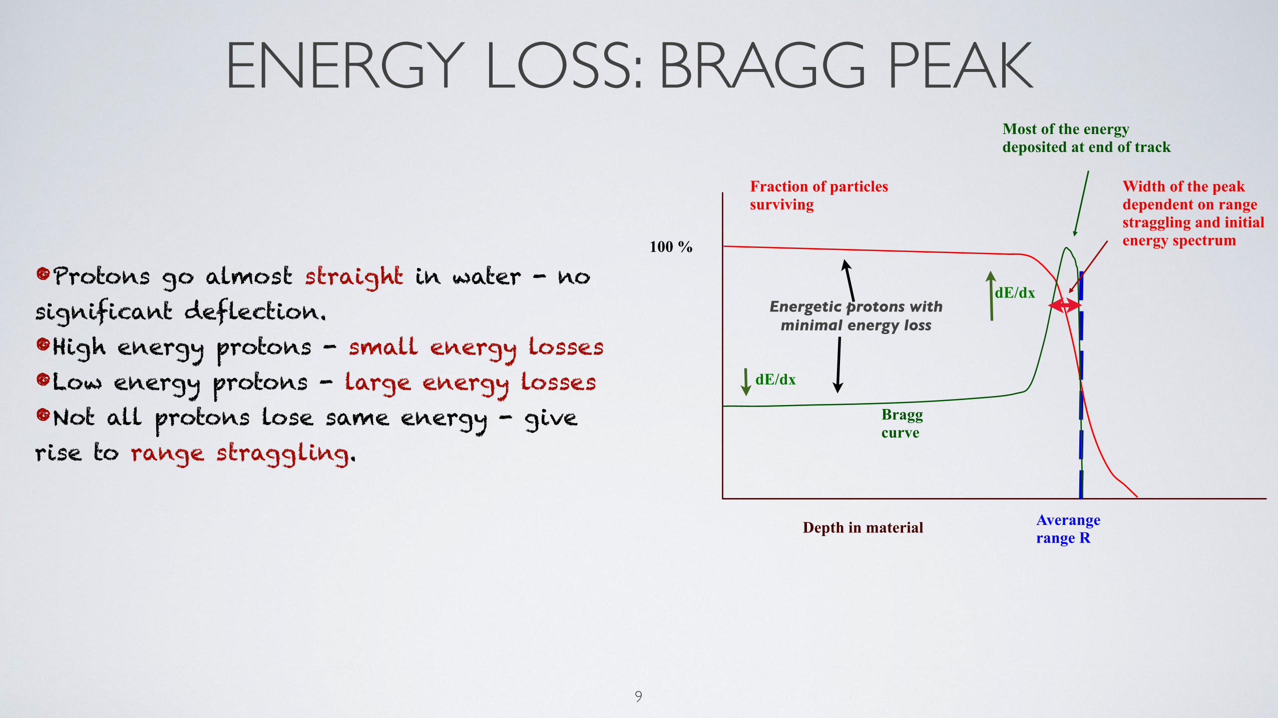
•Protons go almost straight in water - no significant deflection.•High energy protons - small energy losses •Low energy protons - large energy losses•Not all protons lose same energy - give rise to range straggling.
Depth in material
9
Averangerange R
Fraction of particlessurviving
Braggcurve
100 %
Most of the energydeposited at end of track
Width of the peak dependent on range straggling and initial energy spectrum
dE/dx
Energetic protons with minimal energy loss
dE/dx

ENERGY LOSS: RANGE STRAGGLING
Convolution for range straggling
•Range Straggling:Protons lose their energy in individual collisions with electrons.Some protons lose more energy earlier in their journey they do not get to travel that far.Some protons suffer less collisions and get to travel farther.Protons with the same energy E0 have slightly different ranges - Range straggling is Gaussian and is 1% of R0.
10

ENERGY LOSS: RANGE•Energy-range relationship, protons in water
11

ENERGY LOSS: RANGE•Energy-range relationship, protons in water
11
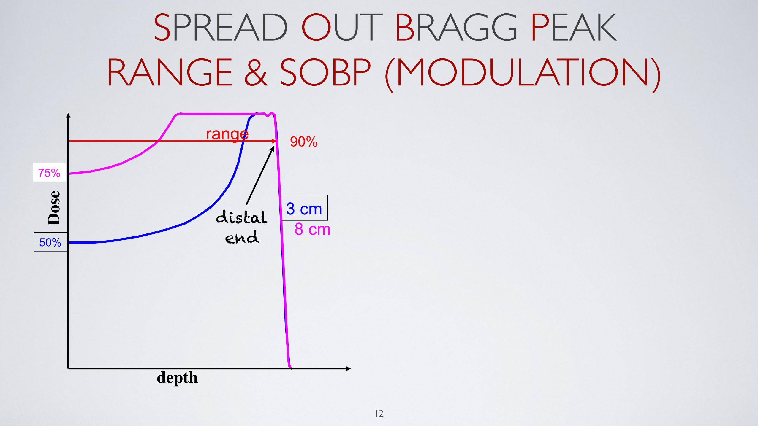
SPREAD OUT BRAGG PEAK RANGE & SOBP (MODULATION)
12
3 cm
50% 8 cm
75%
range 90%
depth!
Dose!
distal end

SPREAD OUT BRAGG PEAK RANGE & SOBP (MODULATION)
12
3 cm
50% 8 cm
75%
range 90%
depth!
Dose!
distal end
3 cm
50% 8 cm
75%
modulation 90%
depth!
Dose!
distal end
proximal end
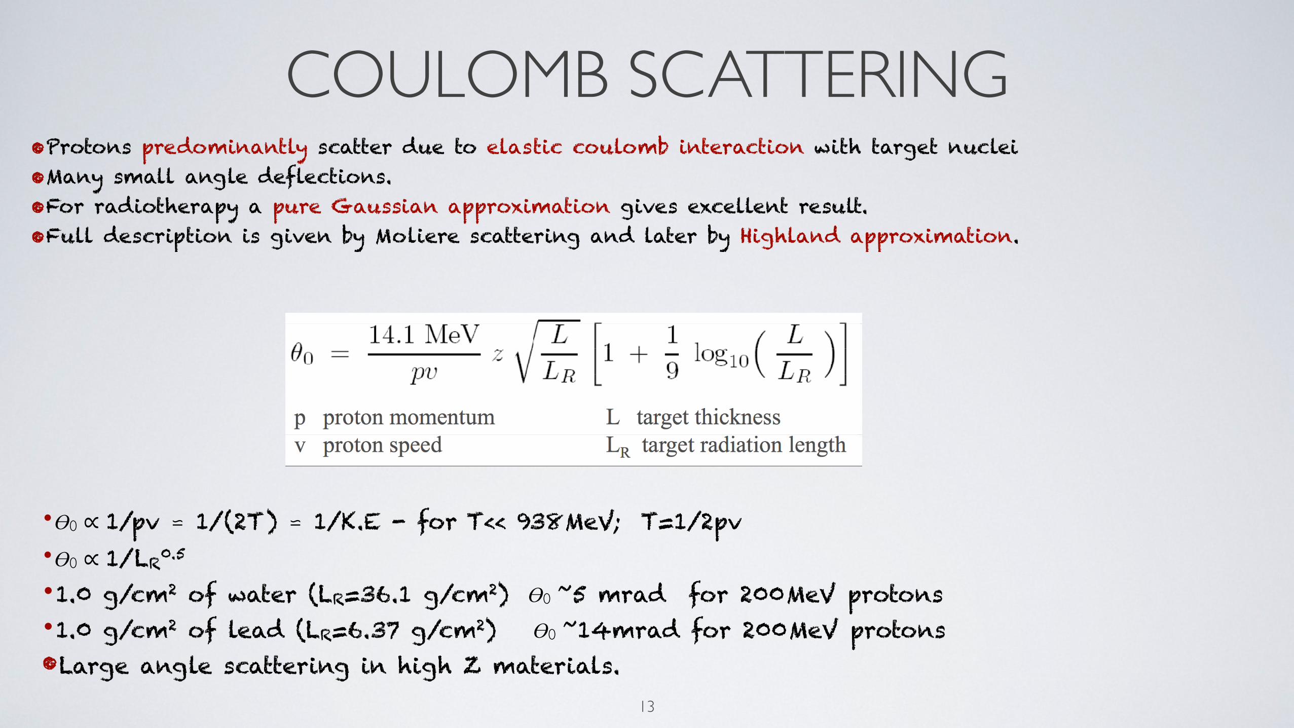
COULOMB SCATTERING•Protons predominantly scatter due to elastic coulomb interaction with target nuclei•Many small angle deflections.•For radiotherapy a pure Gaussian approximation gives excellent result.•Full description is given by Moliere scattering and later by Highland approximation.
•Ɵ0 ∝ 1/pv ⋍ 1/(2T) ⋍ 1/K.E - for T<< 938MeV; T=1/2pv•Ɵ0 ∝ 1/LR0.5 •1.0 g/cm2 of water (LR=36.1 g/cm2) Ɵ0 ~5 mrad for 200MeV protons•1.0 g/cm2 of lead (LR=6.37 g/cm2) Ɵ0 ~14mrad for 200MeV protons•Large angle scattering in high Z materials.
13

COULOMB SCATTERING
14

NUCLEAR INTERACTION
•About 20% of incident protons have inelastic nuclear interactions with the target nuclei.•Reduction of primary proton fluence with depth.•Secondaries charged (p,d,α,recoil target nuclie) ~ 60% of energy - absorbed locally.
neutral (n,γ) ~ 40% of energy - absorbed in surrounding tissues.
•Production of unstable recoil particles (activation) radiation safety dose verification using PET/CT
15

NUCLEAR INTERACTION
16
secondary protons generated in nuclear
interaction
Nuclear interactions take away the dose from the peak
Harald Paganetti

NUCLEAR INTERACTION
•A certain fraction of protons have nuclear interactions with the absorbing matter (tissue), mainly with 16O.
•These protons are lost from the beam.•Janni data suggests 1% loss per cm
17

NUCLEAR INTERACTION
•A certain fraction of protons have nuclear interactions with the absorbing matter (tissue), mainly with 16O.
•These protons are lost from the beam.•Janni data suggests 1% loss per cm
Depth (mm)
Arb.
Units
~70%
17

ANATOMY OF PENCIL BEAM
18
overall shape from increase of dE/dx as
proton slows
1/r2 and transverse size set peak to entrance ratio
nuclear reactions take away from the peak and
add to this region
width from range straggling and beam
energy spread
Along the beam direction Transverse to the beam direction

PENCIL BEAM INTO BROAD BEAM
Dividing the problem into two parts:
The Lateral Problem: How to spread the beam laterally to reach a uniform field up to 24cm or more in diameter?
The Longitudinal Problem:How to modulate the beam energy to reach a uniform field from a given range down to skin?
19

BROAD MODULATED BEAM•Lateral scattering use thick scatterer or beam scanning (scanning magnets) makes the beam laterally uniform
20

BROAD MODULATED BEAM•Lateral scattering use thick scatterer or beam scanning (scanning magnets) makes the beam laterally uniform
ScatteringDS
ScanningUS
20

BROAD MODULATED BEAM•Lateral scattering use thick scatterer or beam scanning (scanning magnets) makes the beam laterally uniform
ScatteringDS
ScanningUS
20
•Pristine Bragg peaks with shifted ranges are superimposed with correct weights and is achieved by pulling back the range - stepped wheel spinning at high speed.

DOUBLE SCATTERING (DS)
! Block and Range compensator"! Second Scatterer"
All layers in a SOBPs are delivered at the same time.
Range Modulator revolves at 600 RPMs
21
Pristine Bragg peak
lateral profile
depth profile
Nozzle

UNIFORM SCANNING (US)
The
! Fixed Scatterer"
! Range Modulator
! Scanning Magnet
The
Beam is delivered layer by layer. At any given time beam is a pristine Bragg peak of certain range
22
Block and compensator
Pristine Bragg peak
lateral profile
depth profile
Nozzle
-0.2
0
0.2
0.4
0.6
0.8
1
1.2
-100 -80 -60 -40 -20 0 20 40 60 80 100
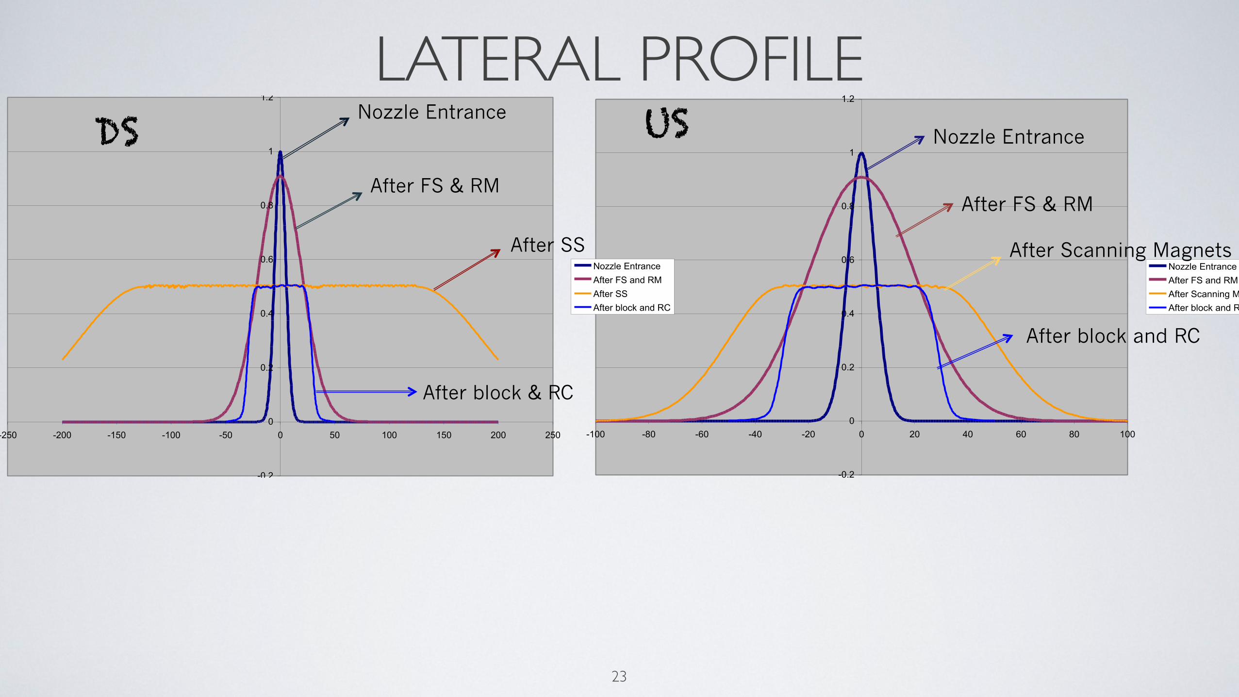
Nozzle EntranceAfter FS and RMAfter Scanning MagnetsAfter block and RC
Nozzle Entrance
After FS & RM
After Scanning Magnets
After block and RC
-0.2
0
0.2
0.4
0.6
0.8
1
1.2
-250 -200 -150 -100 -50 0 50 100 150 200 250
Nozzle EntranceAfter FS and RMAfter SSAfter block and RC
Nozzle Entrance
After FS & RM
After SS
After block & RC
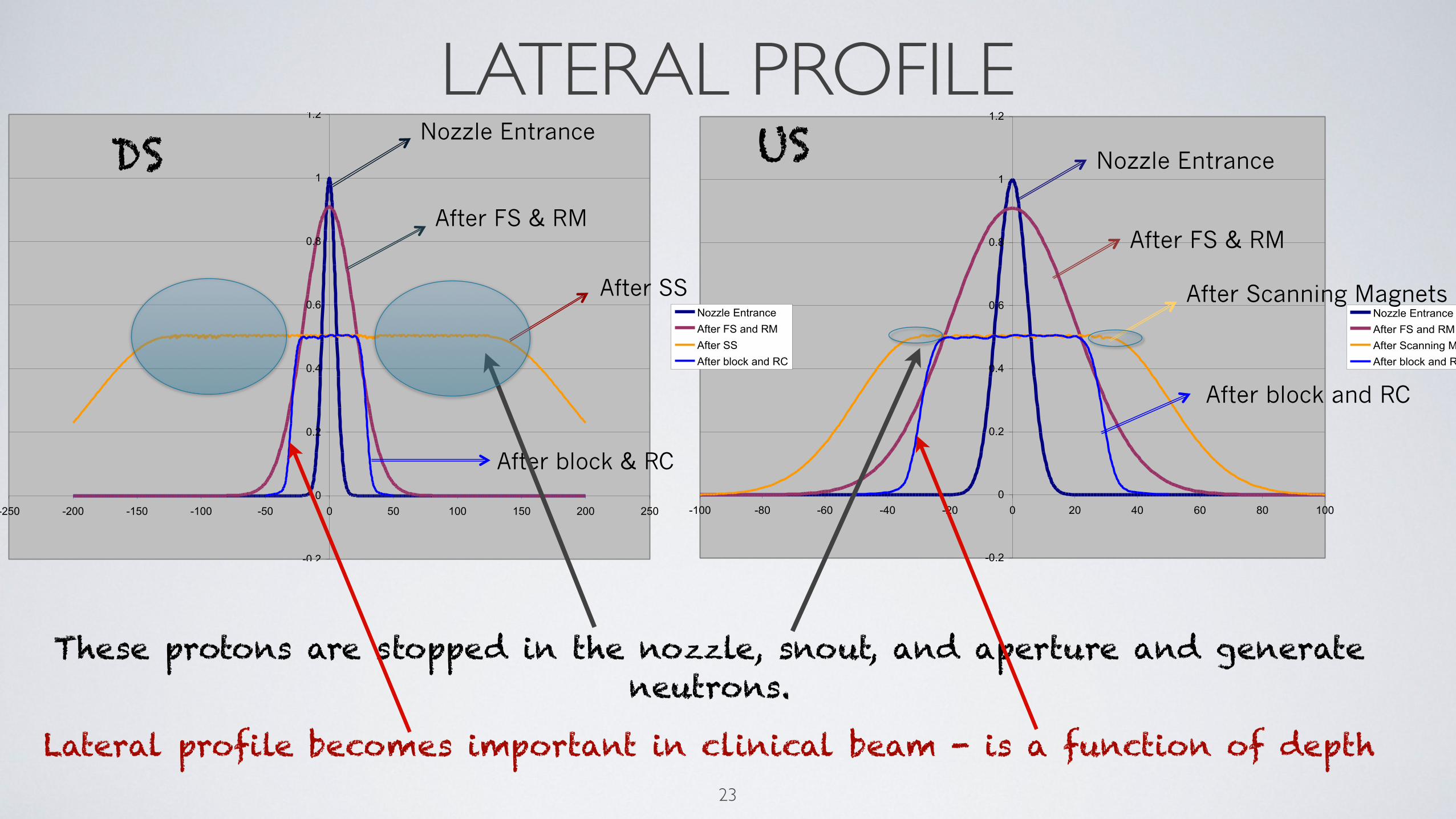
LATERAL PROFILE
23
DS US

-0.2
0
0.2
0.4
0.6
0.8
1
1.2
-100 -80 -60 -40 -20 0 20 40 60 80 100
Nozzle EntranceAfter FS and RMAfter Scanning MagnetsAfter block and RC
Nozzle Entrance
After FS & RM
After Scanning Magnets
After block and RC
-0.2
0
0.2
0.4
0.6
0.8
1
1.2
-250 -200 -150 -100 -50 0 50 100 150 200 250
Nozzle EntranceAfter FS and RMAfter SSAfter block and RC
Nozzle Entrance
After FS & RM
After SS
After block & RC
LATERAL PROFILE
23
DS US
These protons are stopped in the nozzle, snout, and aperture and generate neutrons.
-0.2
0
0.2
0.4
0.6
0.8
1
1.2
-100 -80 -60 -40 -20 0 20 40 60 80 100
Nozzle EntranceAfter FS and RMAfter Scanning MagnetsAfter block and RC
Nozzle Entrance
After FS & RM
After Scanning Magnets
After block and RC
-0.2
0
0.2
0.4
0.6
0.8
1
1.2
-250 -200 -150 -100 -50 0 50 100 150 200 250
Nozzle EntranceAfter FS and RMAfter SSAfter block and RC
Nozzle Entrance
After FS & RM
After SS
After block & RC
LATERAL PROFILE
23
DS US
These protons are stopped in the nozzle, snout, and aperture and generate neutrons.
Lateral profile becomes important in clinical beam - is a function of depth

NEUTRON YIELD
Brass aperture Brass aperture
Opening (target) Opening (target)
Small fields~20% of the beam treats~80% of the beam produces neutrons
Large fields~60% of the beam treats~40% of the beam produces neutrons
24

LATERAL PENUMBRA
25
•What contributes to lateral penumbra

LATERAL PENUMBRA
25
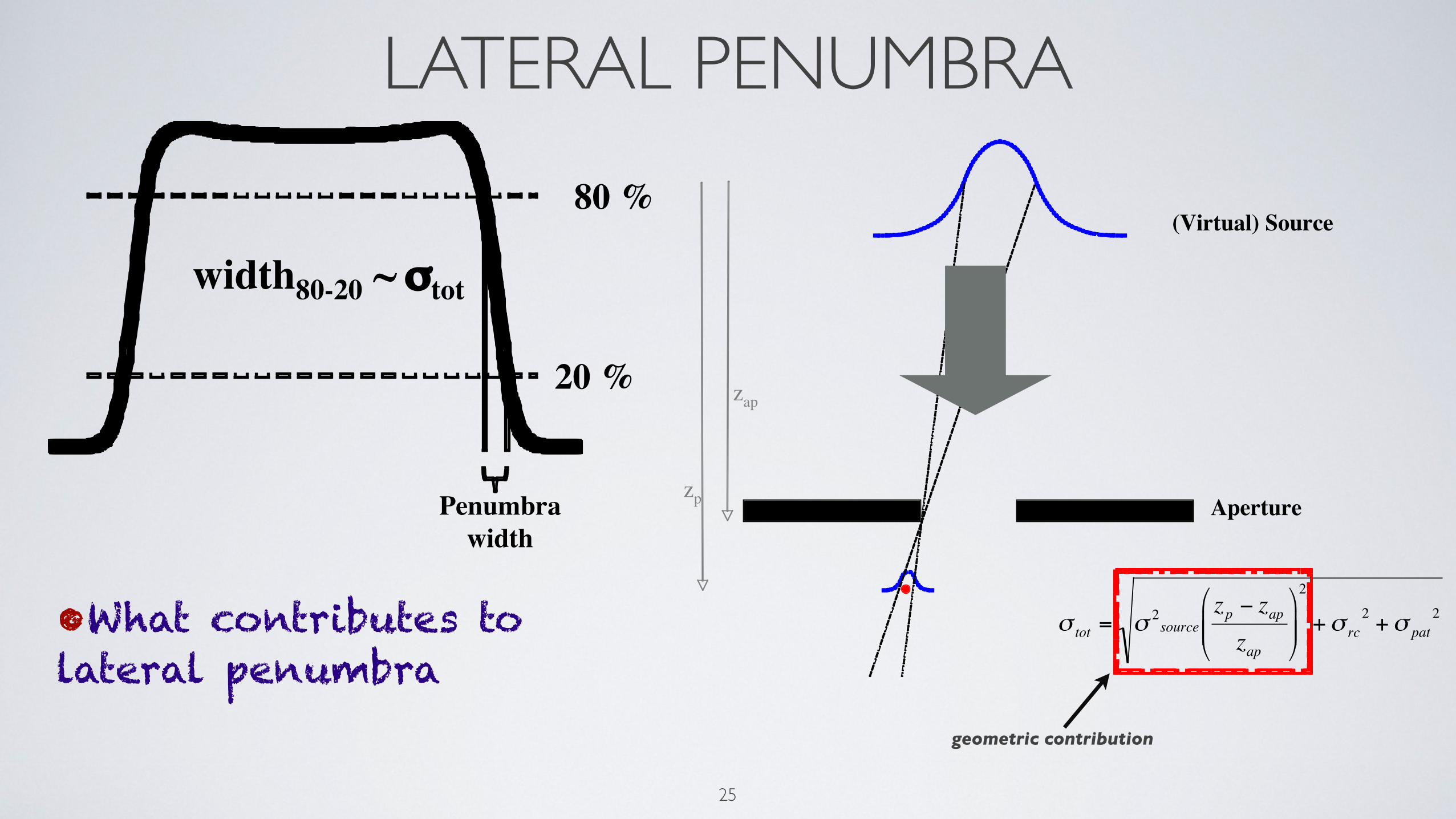
80 %
20 %
Penumbrawidth
width80-20 ~ σtot
•What contributes to lateral penumbra
LATERAL PENUMBRA
25
80 %
20 %
Penumbrawidth
width80-20 ~ σtot
•What contributes to lateral penumbra
zp
zap
€
σ tot = σ 2source
zp − zapzap
$
% & &
'
( ) )
2
+σ rc2 +σ pat
2
(Virtual) Source
Aperture
geometric contribution

LATERAL PENUMBRA
26
σ2 (
)
σtot
σsource
σpat + σrc
22
2
2patrc
ap
appsourcetot z
zzσσσσ ++"
"#
$%%&
' −=
Source: S. Safai
At shallow depth lateral penumbra is dominated by the source size.
As depth in the patient increases patient scatter starts to increase.
Beyond ~16cm patient scatter becomes dominant.

RELATIVE BIOLOGICAL EFFECTIVENESS (RBE)
What is the difference in biological effectiveness between particles and photons?
Dosis
0 1 2 3 4 5 6 7 8
Survival
0.001
0.01
0.1
1
Dose [Gy]
Sur
vivi
ng F
ract
ion
RBE=Dx/Dp
X-rays
Particles
27

RELATIVE BIOLOGICAL EFFECTIVENESS (RBE)
Dose per fraction [Gy]
1 10
RB
E
0.5
1.0
1.5
2.0
2.5
1.07±0.12
RBE = 1.1 for protons (general consensus)
RBE for heavier particles (C12) can be as high as 3.5
28

RELATIVE BIOLOGICAL EFFECTIVENESS (RBE)
RBE increases with depth because linear energy transfer (LET) increases with depth.
For protons we assume 1.1 flat for the entire SOBP.
Biological effective range increases by 1-2mm. 29
Carbon 12
Protons

LINEAR ENERGY TRANSFER (LET)LET of charged particle in a medium is the ratio of dE/dl, where dE is the average energy locally imparted to the medium by a charged particle in traversing a distance of dl.
LET < 10 KeV/μm low LETLET > 10 KeVμm high LET
250 kVp X-Rays: 2 keV/μm3 MeV X-Rays: 0.3 keV/μm14 MeV neutrons: 12 keV/μmheavy charged particles: 100-200 keV/μm10 keV electrons: 2.3 keV/μm
30

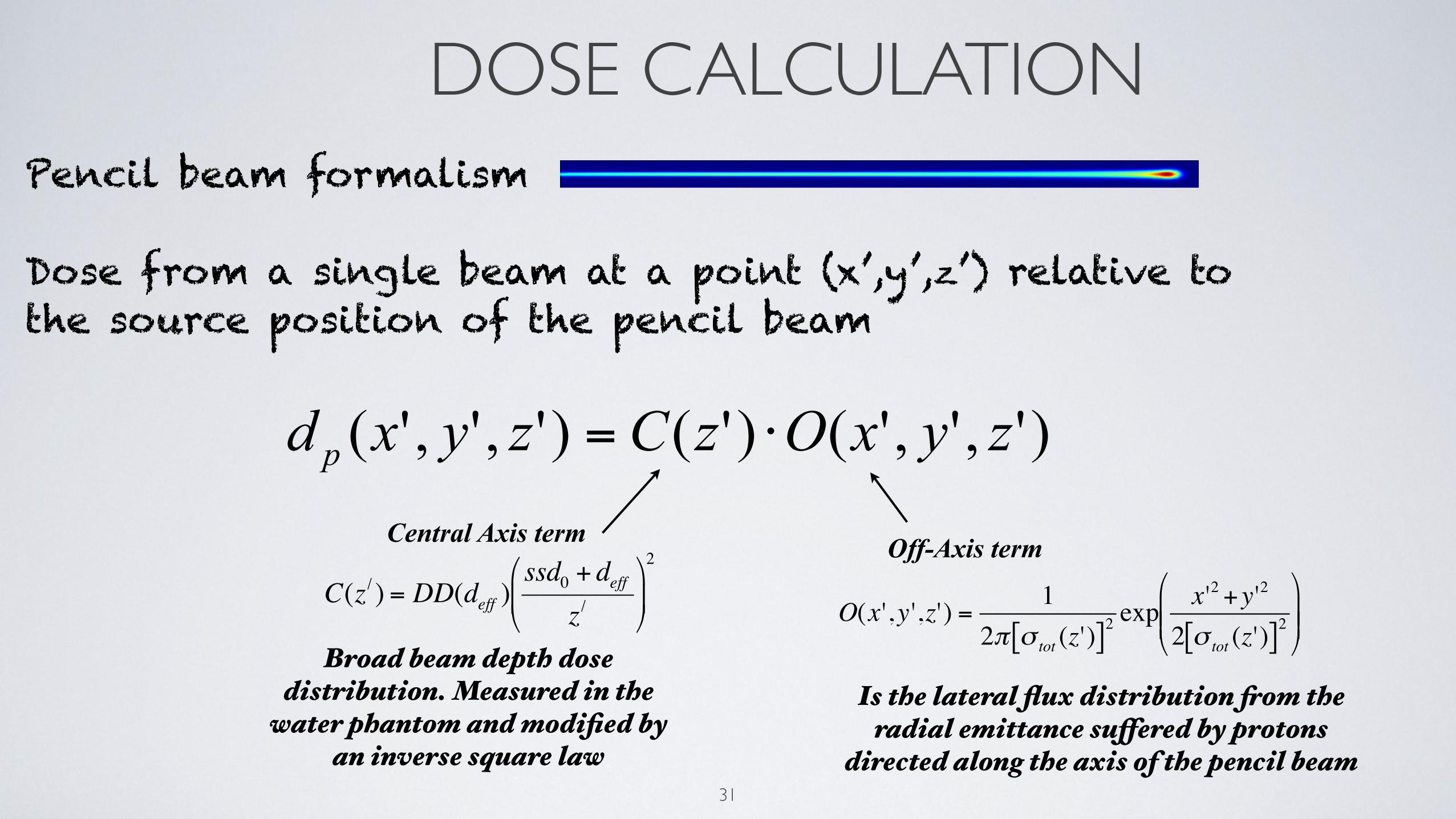
DOSE CALCULATIONPencil beam formalism
Dose from a single beam at a point (x’,y’,z’) relative to the source position of the pencil beam
31
DOSE CALCULATIONPencil beam formalism
Dose from a single beam at a point (x’,y’,z’) relative to the source position of the pencil beam
31
)',','()'()',','( zyxOzCzyxd p ⋅=
Central Axis term
€
C(z / ) = DD(deff )ssd0 + deff
z /"
# $
%
& '
2
Broad beam depth dose distribution. Measured in the
water phantom and modified by an inverse square law €
O(x',y ',z') =1
2π σ tot (z')[ ]2exp x'2 +y'2
2 σ tot (z')[ ]2$
% & &
'
( ) )
Off-Axis term
Is the lateral flux distribution from the radial emittance suffered by protons
directed along the axis of the pencil beam

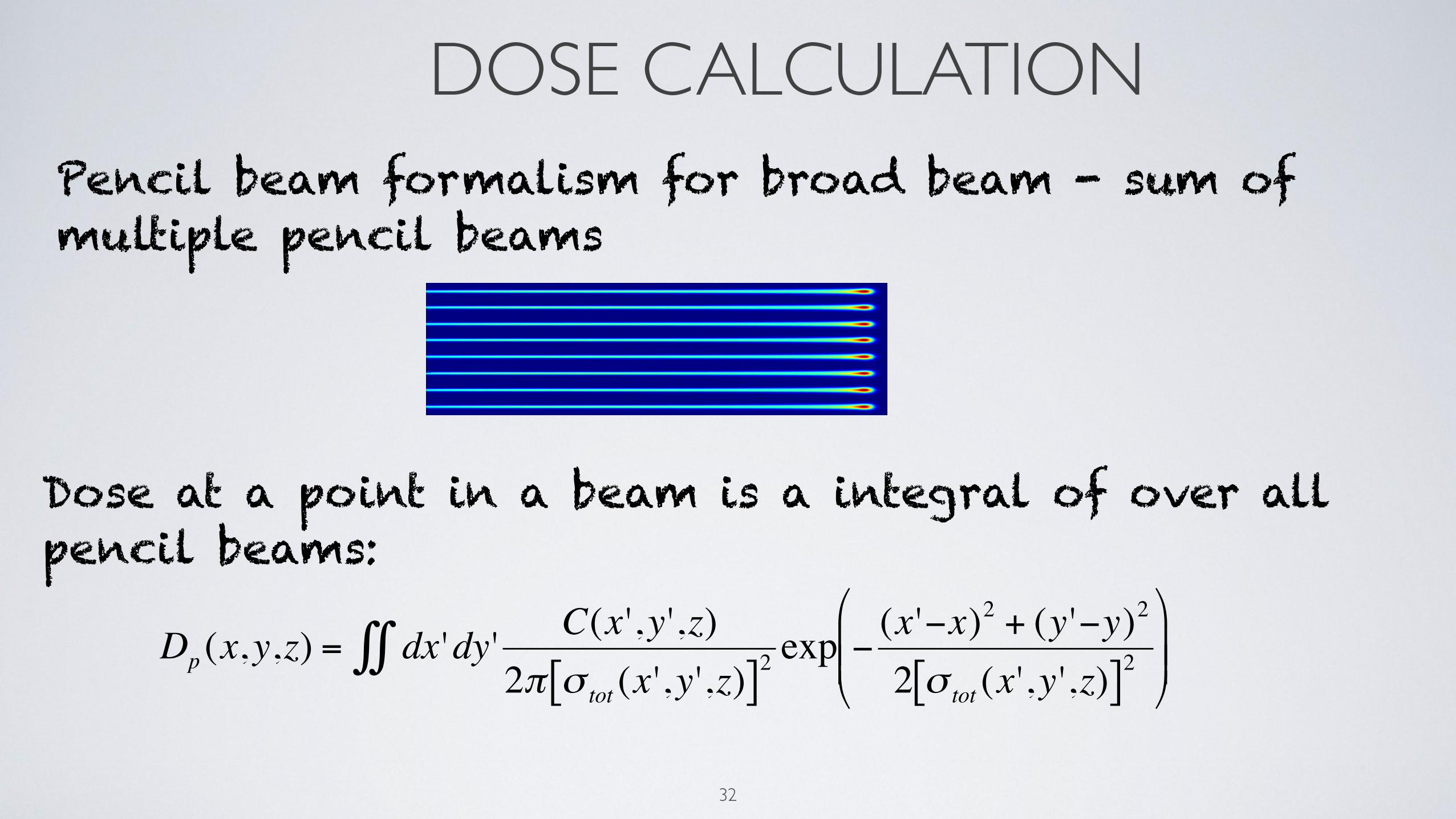
DOSE CALCULATIONPencil beam formalism for broad beam - sum of multiple pencil beams
32

DOSE CALCULATIONPencil beam formalism for broad beam - sum of multiple pencil beams
32
DOSE CALCULATIONPencil beam formalism for broad beam - sum of multiple pencil beams
32
Dose at a point in a beam is a integral of over all pencil beams:
€
Dp (x,y,z) = dx 'dy' C(x ',y',z)2π σ tot (x ',y',z)[ ]2
exp − (x '−x)2 + (y '−y)2
2 σ tot (x',y ',z)[ ]2%
& ' '
(
) * * ∫∫

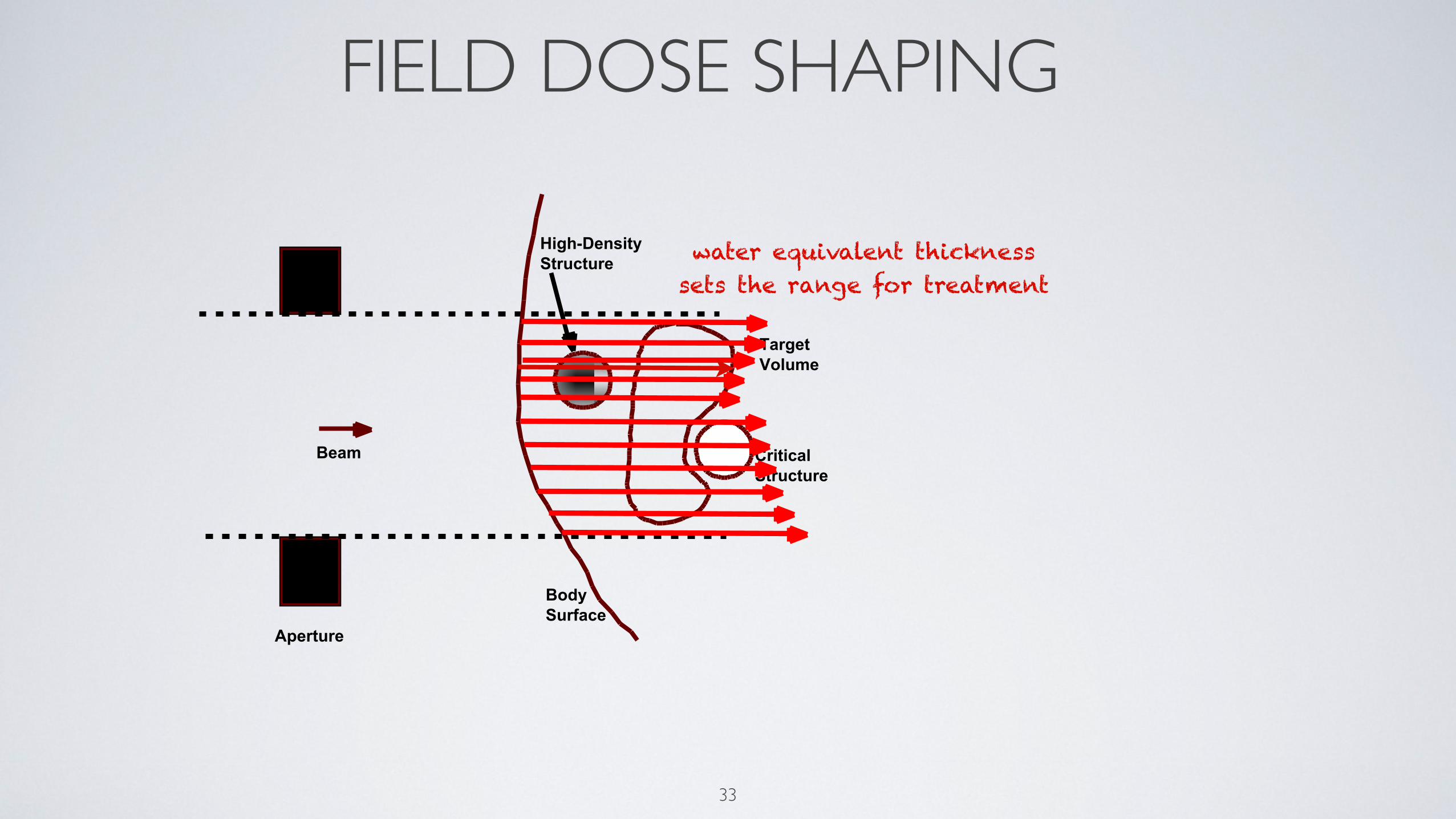
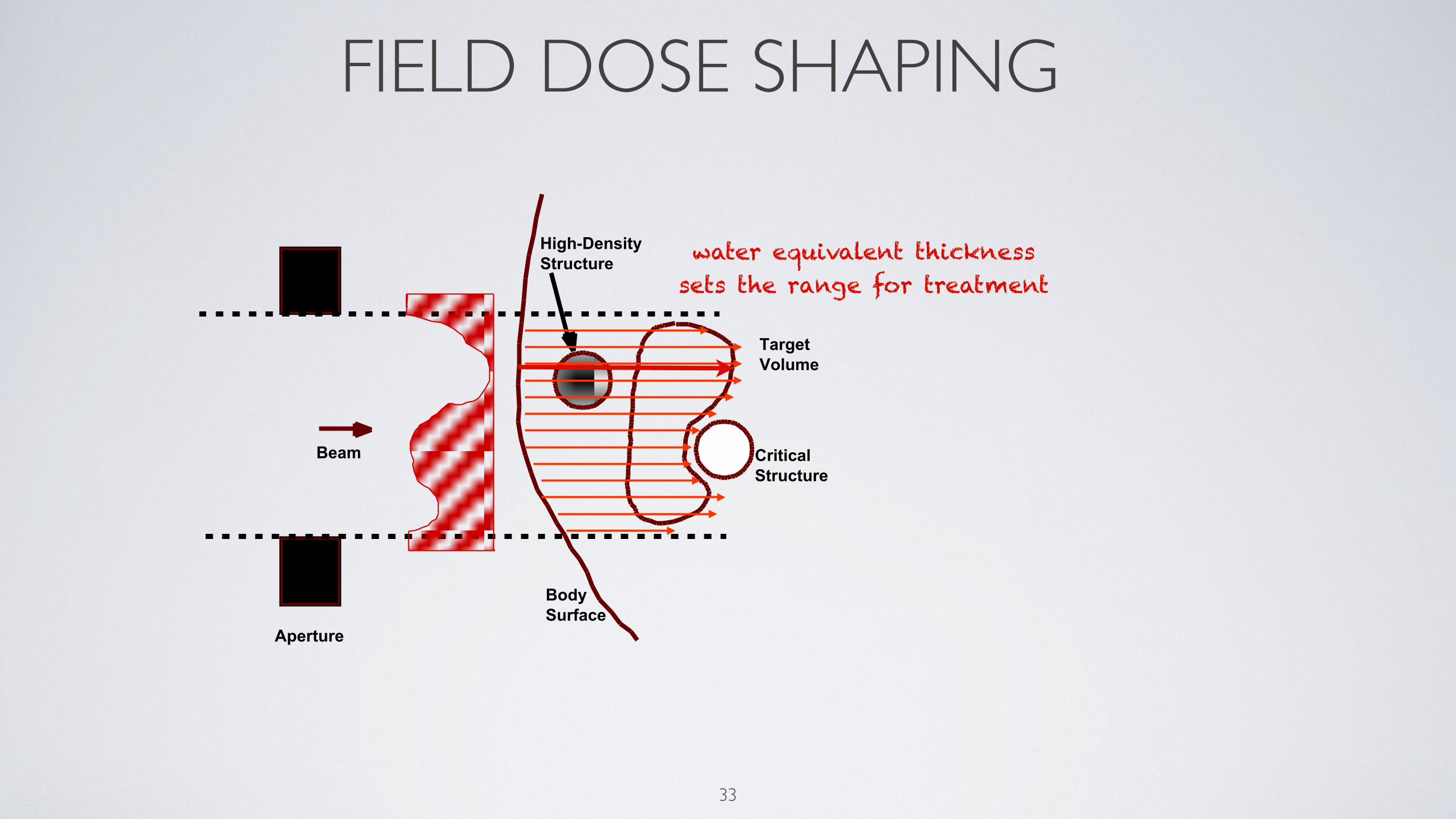
FIELD DOSE SHAPING
33

FIELD DOSE SHAPING
33
High-DensityStructure
BodySurface
CriticalStructure
TargetVolume
Beam

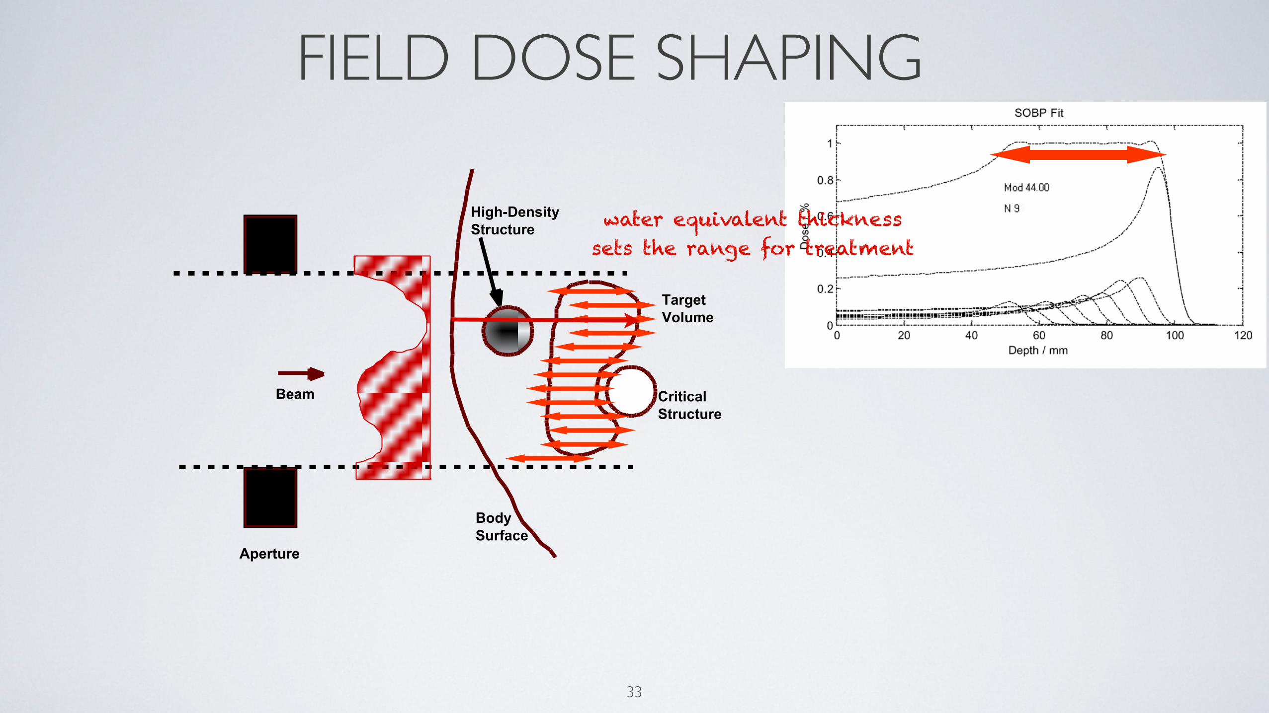
FIELD DOSE SHAPING
33
High-DensityStructure
BodySurface
CriticalStructure
TargetVolume
Beam
water equivalent thicknesssets the range for treatment
FIELD DOSE SHAPING
33
Aperture
High-DensityStructure
BodySurface
CriticalStructure
TargetVolume
Beam
water equivalent thicknesssets the range for treatment
FIELD DOSE SHAPING
33
Aperture
High-DensityStructure
BodySurface
CriticalStructure
TargetVolume
Beam
water equivalent thicknesssets the range for treatment
FIELD DOSE SHAPING
33
Aperture
High-DensityStructure
BodySurface
CriticalStructure
TargetVolume
Beam
water equivalent thicknesssets the range for treatment
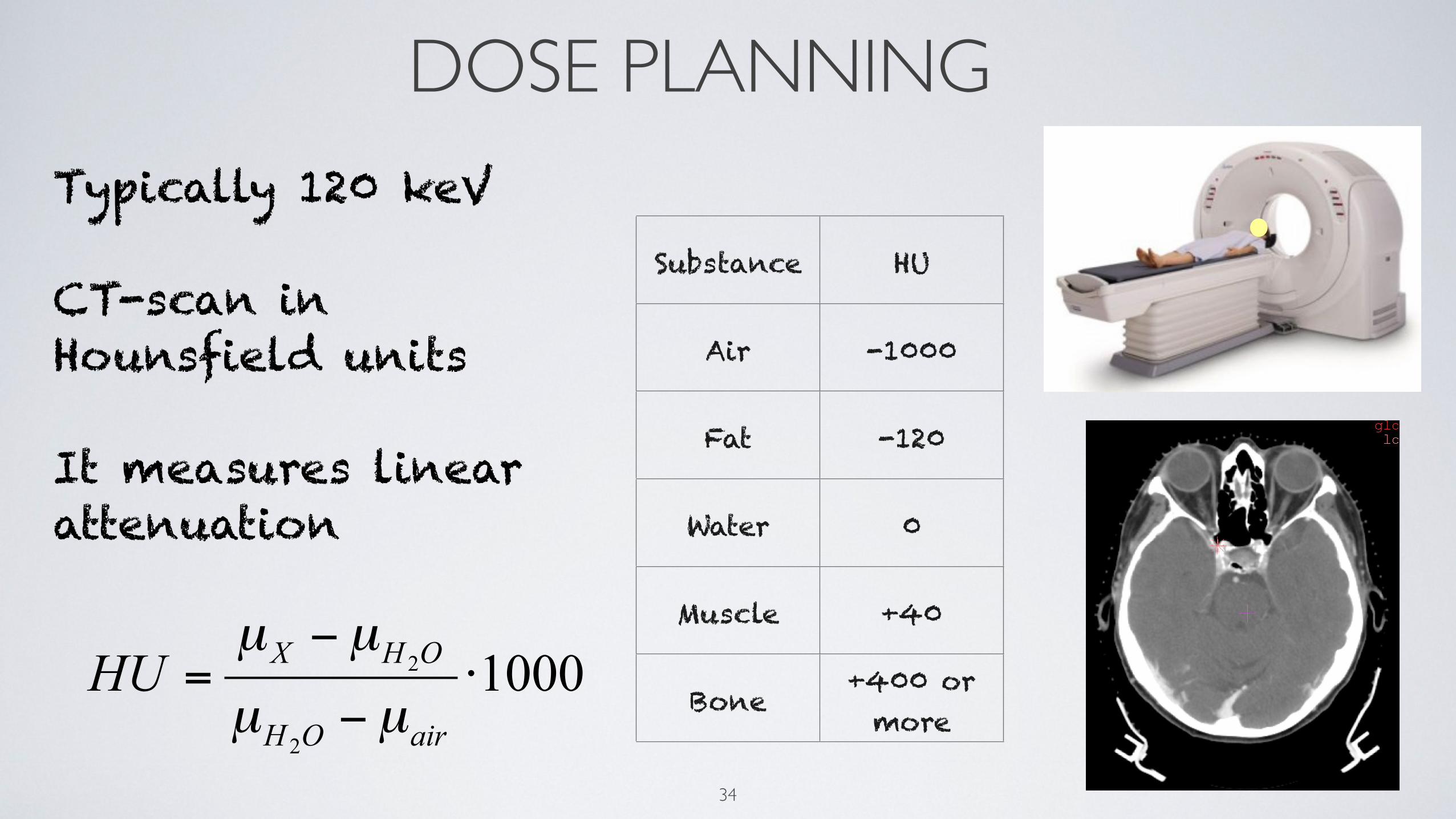
DOSE PLANNING
34
Typically 120 keV
CT-scan in Hounsfield units
It measures linear attenuation
10002
2 ⋅−
−=
airOH
OHXHUµµ
µµ
Substance HU
Air -1000
Fat -120
Water 0
Muscle +40
Bone +400 or more
DOSE PLANNING
35
0
0.25
0.5
0.75
1
1.25
1.5
-1000 -750 -500 -250 0 250 500 750 1000 1250 1500
CT Value
Rel
ativ
e st
oppi
ng p
ower TPS
Measured
Water
Lung
Air
Bone
Metal
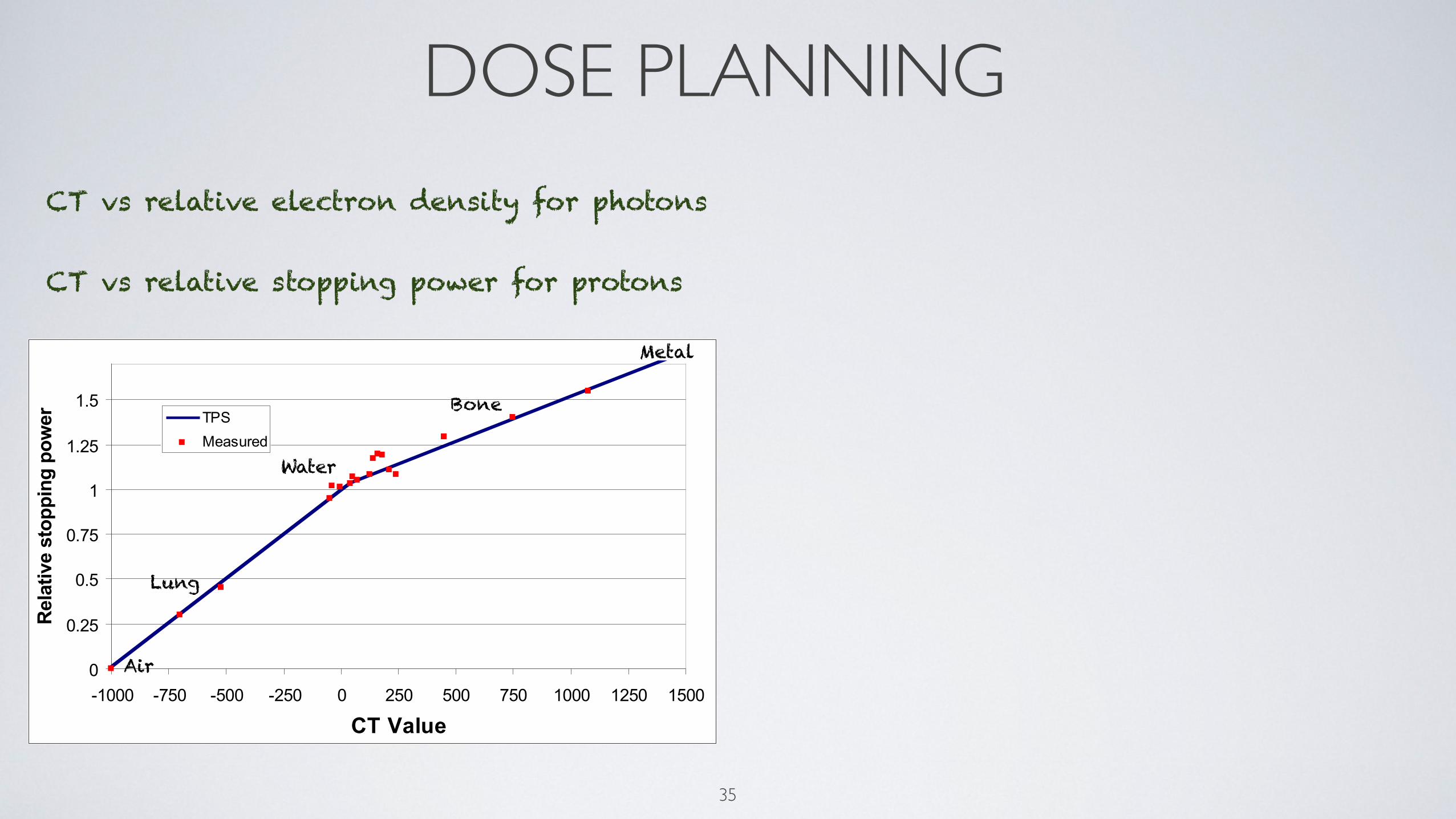
CT vs relative electron density for photons
CT vs relative stopping power for protons

DOSE PLANNING
35
0
0.25
0.5
0.75
1
1.25
1.5
-1000 -750 -500 -250 0 250 500 750 1000 1250 1500
CT Value
Rel
ativ
e st
oppi
ng p
ower TPS
Measured
Water
Lung
Air
Bone
Metal
Photons ProtonsElectron density Proton stopping power
80
100
120
140
160
180
200
0 5 10 15 20 25 30Depth (cm)
Dos
e (%
)
60
40
20
0
10 MV Photon
Proton SOBP (18cm)
Any error in CT will result in uncertainty in
proton range calculations
CT vs relative electron density for photons
CT vs relative stopping power for protons
DOSE PLANNING
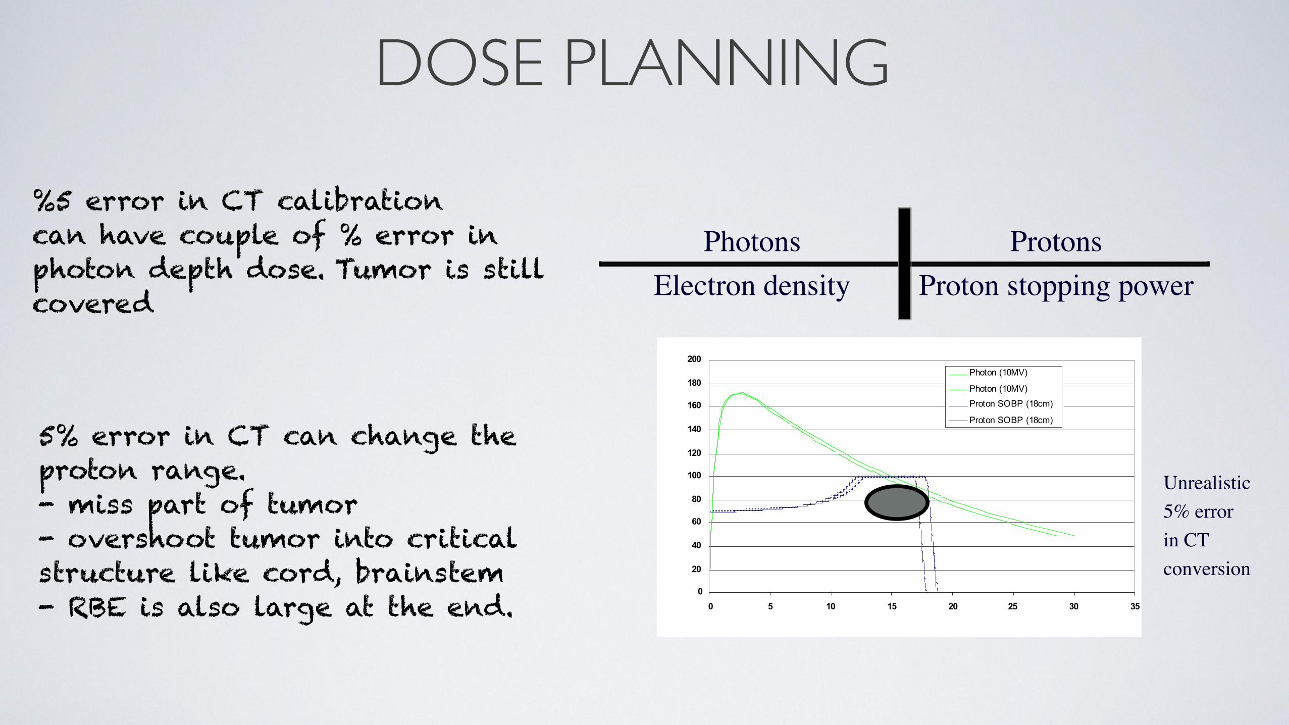
%5 error in CT calibrationcan have couple of % error in photon depth dose. Tumor is still covered
DOSE PLANNING
%5 error in CT calibrationcan have couple of % error in photon depth dose. Tumor is still covered
Photons ProtonsElectron density Proton stopping power
0
20
40
60
80
100
120
140
160
180
200
0 5 10 15 20 25 30 35
Photon (10MV)
Photon (10MV)
Proton SOBP (18cm)
Proton SOBP (18cm)
Unrealistic5% errorin CT conversion
5% error in CT can change the proton range.- miss part of tumor- overshoot tumor into critical structure like cord, brainstem- RBE is also large at the end.

SUMMARY
37

SUMMARY•Physics: Energy loss, scattering, nuclear interactions lead to Bragg peak shaped dose distribution.•Pencil beam is converted to a broad beam by lateral and longitudinal spreading.•Range straggling modifies the beam at distal end along the direction of beam ~1% of the Range.•Lateral penumbra modifies the beam in a transverse direction to the beam ~2% of the Range.•RBE modifies the does depths and increases range by ~2mm.•Dose calculation based on pencil beam algorithm. •Sculpting raw proton beam into clinical deliverable beam.
37
THANK YOU
38