perils of proton therapy
TRANSCRIPT
Perils of Proton Therapy
Jatinder R Palta PhDUniversity of Florida
Department of Radiation OncologyGainesville, Florida
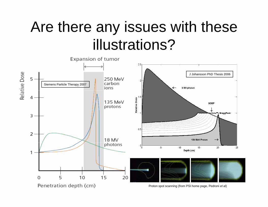
Are there any issues with these illustrations?
J Johansson PhD Thesis 2006
Siemens Particle Therapy 2007
Proton spot scanning (from PSI home page, Pedroni et al)
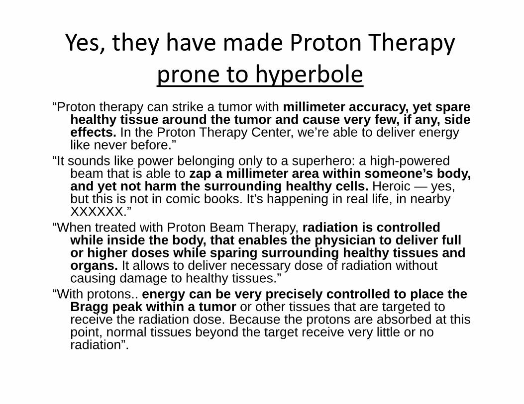
Yes, they have made Proton Therapy prone to hyperboleprone to hyperbole
“Proton therapy can strike a tumor with millimeter accuracy, yet spare healthy tissue around the tumor and cause very few, if any, side y y , y,effects. In the Proton Therapy Center, we’re able to deliver energy like never before.”
“It sounds like power belonging only to a superhero: a high-powered beam that is able to zap a millimeter area within someone’s body,beam that is able to zap a millimeter area within someone s body, and yet not harm the surrounding healthy cells. Heroic — yes, but this is not in comic books. It’s happening in real life, in nearby XXXXXX.”
“When treated with Proton Beam Therapy radiation is controlledWhen treated with Proton Beam Therapy, radiation is controlled while inside the body, that enables the physician to deliver full or higher doses while sparing surrounding healthy tissues and organs. It allows to deliver necessary dose of radiation without causing damage to healthy tissues ”causing damage to healthy tissues.
“With protons.. energy can be very precisely controlled to place the Bragg peak within a tumor or other tissues that are targeted to receive the radiation dose. Because the protons are absorbed at this point normal tiss es be ond the target recei e er little or nopoint, normal tissues beyond the target receive very little or no radiation”.
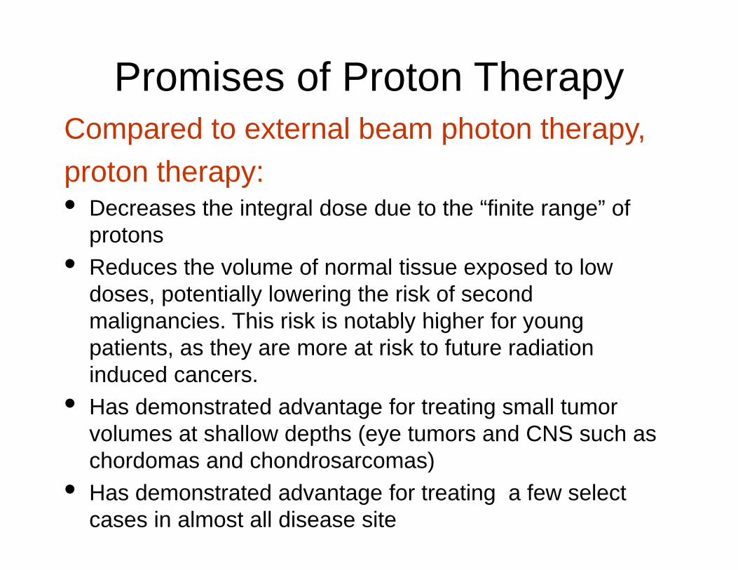
Promises of Proton TherapyCompared to external beam photon therapy,proton therapy:proton therapy:• Decreases the integral dose due to the “finite range” of
protons• Reduces the volume of normal tissue exposed to low
doses, potentially lowering the risk of second malignancies This risk is notably higher for youngmalignancies. This risk is notably higher for young patients, as they are more at risk to future radiation induced cancers.
• Has demonstrated advantage for treating small tumor volumes at shallow depths (eye tumors and CNS such as chordomas and chondrosarcomas)chordomas and chondrosarcomas)
• Has demonstrated advantage for treating a few select cases in almost all disease site
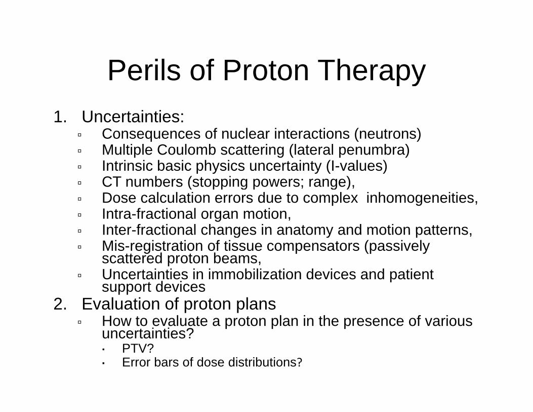
Perils of Proton TherapyPerils of Proton Therapy1. Uncertainties:
C f l i i ( ) Consequences of nuclear interactions (neutrons) Multiple Coulomb scattering (lateral penumbra) Intrinsic basic physics uncertainty (I-values)
CT numbers (stopping powers; range) CT numbers (stopping powers; range), Dose calculation errors due to complex inhomogeneities, Intra-fractional organ motion, Inter-fractional changes in anatomy and motion patterns Inter fractional changes in anatomy and motion patterns, Mis-registration of tissue compensators (passively
scattered proton beams, Uncertainties in immobilization devices and patient
support devicessupport devices2. Evaluation of proton plans
How to evaluate a proton plan in the presence of various uncertainties?uncertainties? PTV? Error bars of dose distributions?
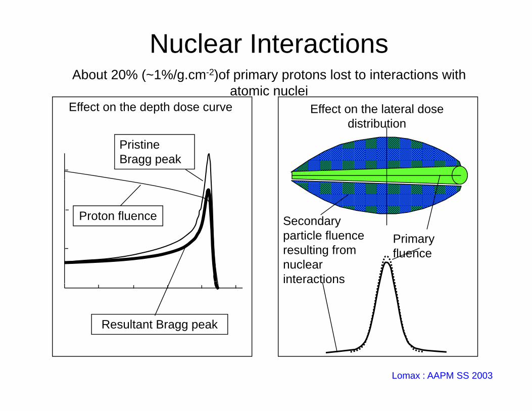
Nuclear InteractionsAbout 20% (~1%/g cm-2)of primary protons lost to interactions with
Effect on the lateral dose distribution
Effect on the depth dose curve
About 20% ( 1%/g.cm )of primary protons lost to interactions with atomic nuclei
Pristine Bragg peak
Secondary ti l fl
Proton fluenceparticle fluence resulting from nuclear interactions
Primary fluence
Resultant Bragg peak
Lomax : AAPM SS 2003
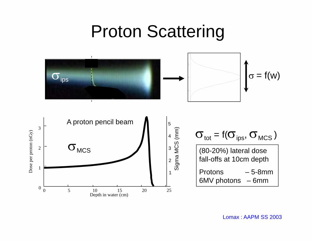
Proton Scattering
= f(w) = f(w)ips
3
Gy)
A proton pencil beam
t t = f(i MCS )4
5
mm
)
2
se p
er p
roto
n (n
G tot = f(ips, MCS )
2
3
4
igm
a M
CS
(m
MCS (80-20%) lateral dose fall-offs at 10cm depth
0 5 10 15 20 250
1
Depth in water (cm)
Dos
1Si Protons – 5-8mm
6MV photons – 6mm
p ( )
Lomax : AAPM SS 2003
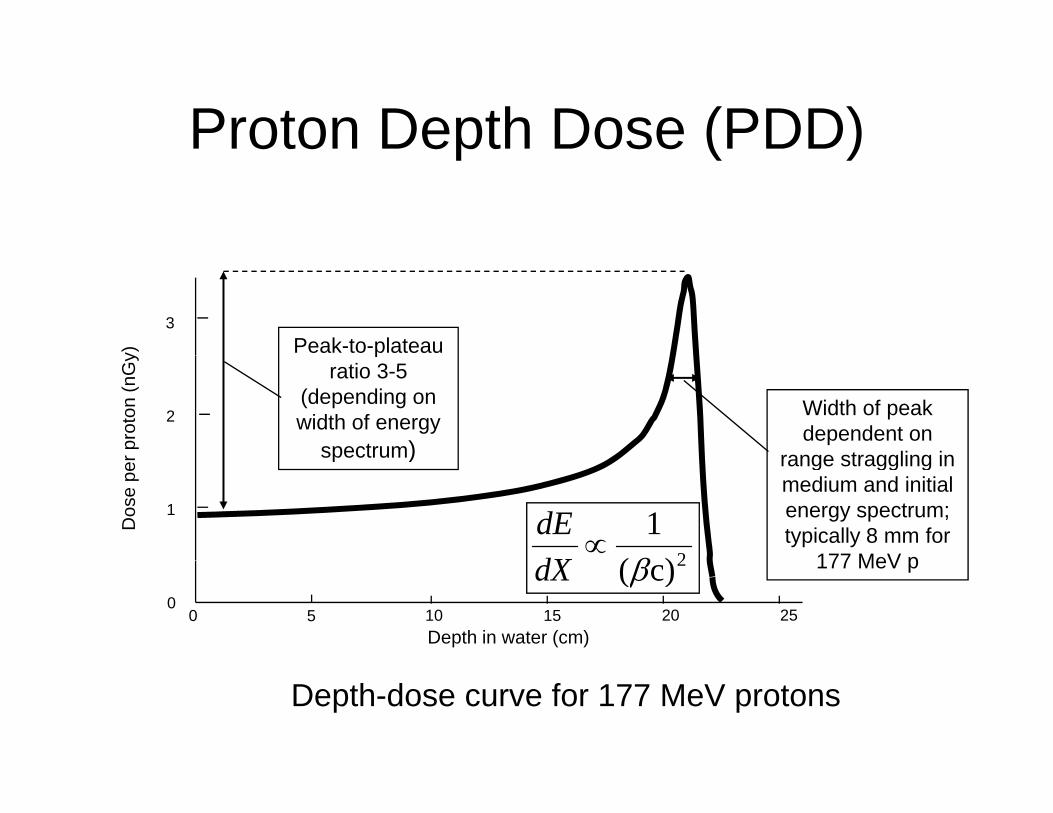
Proton Depth Dose (PDD)p ( )
3
y) Peak-to-plateau
2
r pro
ton
(nG
y
Width of peak dependent on
range straggling in
pratio 3-5
(depending on width of energy
spectrum)
1
Dos
e pe
r
2)(1
dXdE
range straggling in medium and initial energy spectrum; typically 8 mm for
177 MeV p
p )
0 5 10 15 20 250
Depth in water (cm)
2c)(dX 177 MeV p
Depth-dose curve for 177 MeV protons
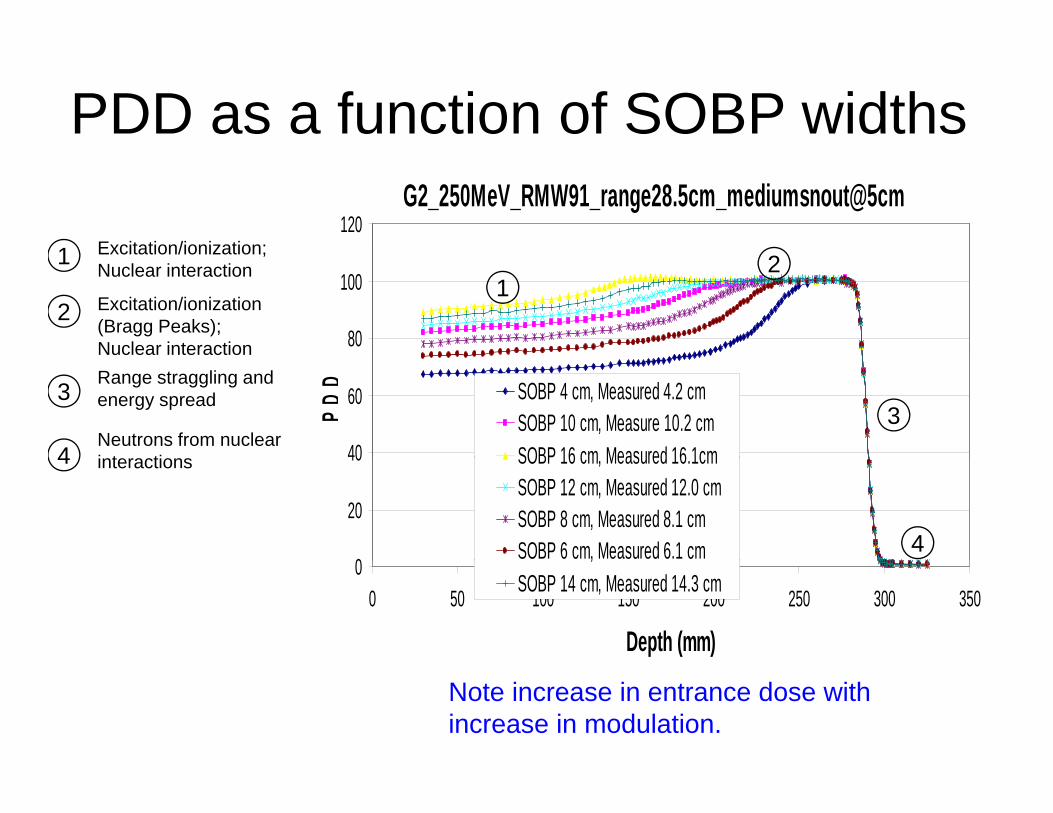
PDD as a function of SOBP widthsG2_250MeV_RMW91_range28.5cm_mediumsnout@5cm
1201 Excitation/ionization;
80
100 121
2
Excitation/ionization;Nuclear interaction
Excitation/ionization (Bragg Peaks);Nuclear interaction
40
60
PDD SOBP 4 cm, Measured 4.2 cm
SOBP 10 cm, Measure 10.2 cmSOBP 16 cm Measured 16 1cm
33
4
Range straggling and energy spread
Neutrons from nuclear i t ti
0
20
40 SOBP 16 cm, Measured 16.1cmSOBP 12 cm, Measured 12.0 cmSOBP 8 cm, Measured 8.1 cmSOBP 6 cm, Measured 6.1 cm 4
4 interactions
00 50 100 150 200 250 300 350
Depth (mm)
,SOBP 14 cm, Measured 14.3 cm
Note increase in entrance dose with increase in modulation.
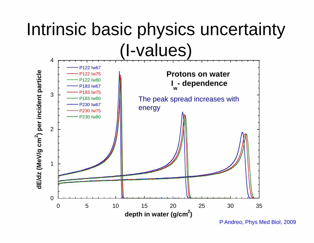
Intrinsic basic physics uncertainty (I l )
4
Protons on waterP122 Iw67P122 Iw75cl
e
(I-values)
3
Protons on water I
w- dependenceP122 Iw80
P183 Iw67P183 Iw75P183 Iw80P230 Iw67de
nt p
artic
The peak spread increases with energ
2
P230 Iw75P230 Iw80
2 ) per
inci
d energy
1MeV
/g c
m2
0
dE/d
z (
00 5 10 15 20 25 30 35
depth in water (g/cm2)P Andreo, Phys Med Biol, 2009
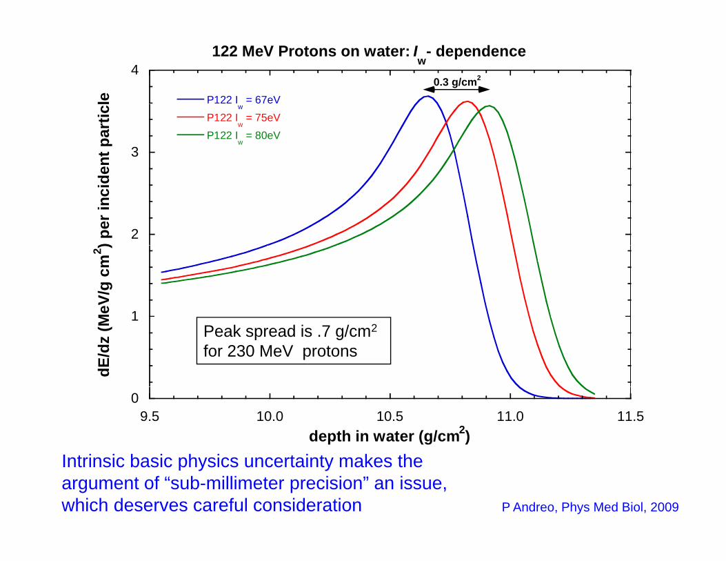
4122 MeV Protons on water: I
w- dependence
P122 I = 67eVle0.3 g/cm2
3
w
P122 Iw = 75eV
P122 Iw = 80eV
ent p
artic
l
2) per
inci
d
1MeV
/g c
m2 )
1
dE/d
z (M Peak spread is .7 g/cm2
for 230 MeV protons
09.5 10.0 10.5 11.0 11.5
depth in water (g/cm2)Intrinsic basic ph sics ncertaint makes the
P Andreo, Phys Med Biol, 2009
Intrinsic basic physics uncertainty makes the argument of “sub-millimeter precision” an issue, which deserves careful consideration
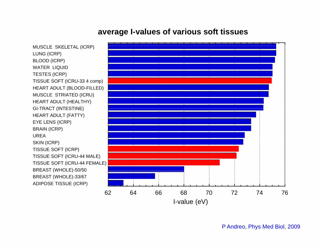
MUSCLE SKELETAL (ICRP)
average I-values of various soft tissues
TESTES (ICRP) WATER LIQUID BLOOD (ICRP) LUNG (ICRP) MUSCLE SKELETAL (ICRP)
GI TRACT (INTESTINE)HEART ADULT (HEALTHY)MUSCLE STRIATED (ICRU) HEART ADULT (BLOOD-FILLED)TISSUE SOFT (ICRU-33 4 comp)
UREA BRAIN (ICRP) EYE LENS (ICRP) HEART ADULT (FATTY)GI-TRACT (INTESTINE)
BREAST (WHOLE)-50/50TISSUE SOFT (ICRU-44 FEMALE)TISSUE SOFT (ICRU-44 MALE)TISSUE SOFT (ICRP) SKIN (ICRP)
62 64 66 68 70 72 74 76ADIPOSE TISSUE (ICRP) BREAST (WHOLE)-33/67BREAST (WHOLE) 50/50
I-value (eV)I-value (eV)
P Andreo, Phys Med Biol, 2009
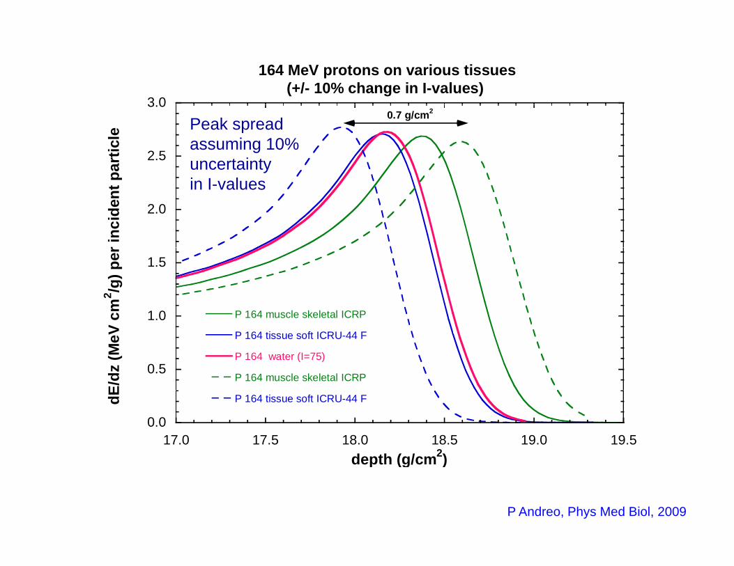
3 0
164 MeV protons on various tissues(+/- 10% change in I-values)
2.5
3.0pa
rtic
le 0.7 g/cm2
Peak spread assuming 10% uncertainty
2.0
r inc
iden
t p in I-values
1.0
1.5
P 164 muscle skeletal ICRPcm2 /g
) per
0.5
1.0P 164 tissue soft ICRU-44 F
P 164 water (I=75)
P 164 muscle skeletal ICRP
E/dz
(MeV
c
0.017.0 17.5 18.0 18.5 19.0 19.5
P 164 tissue soft ICRU-44 FdE
depth (g/cm2)depth (g/cm )
P Andreo, Phys Med Biol, 2009
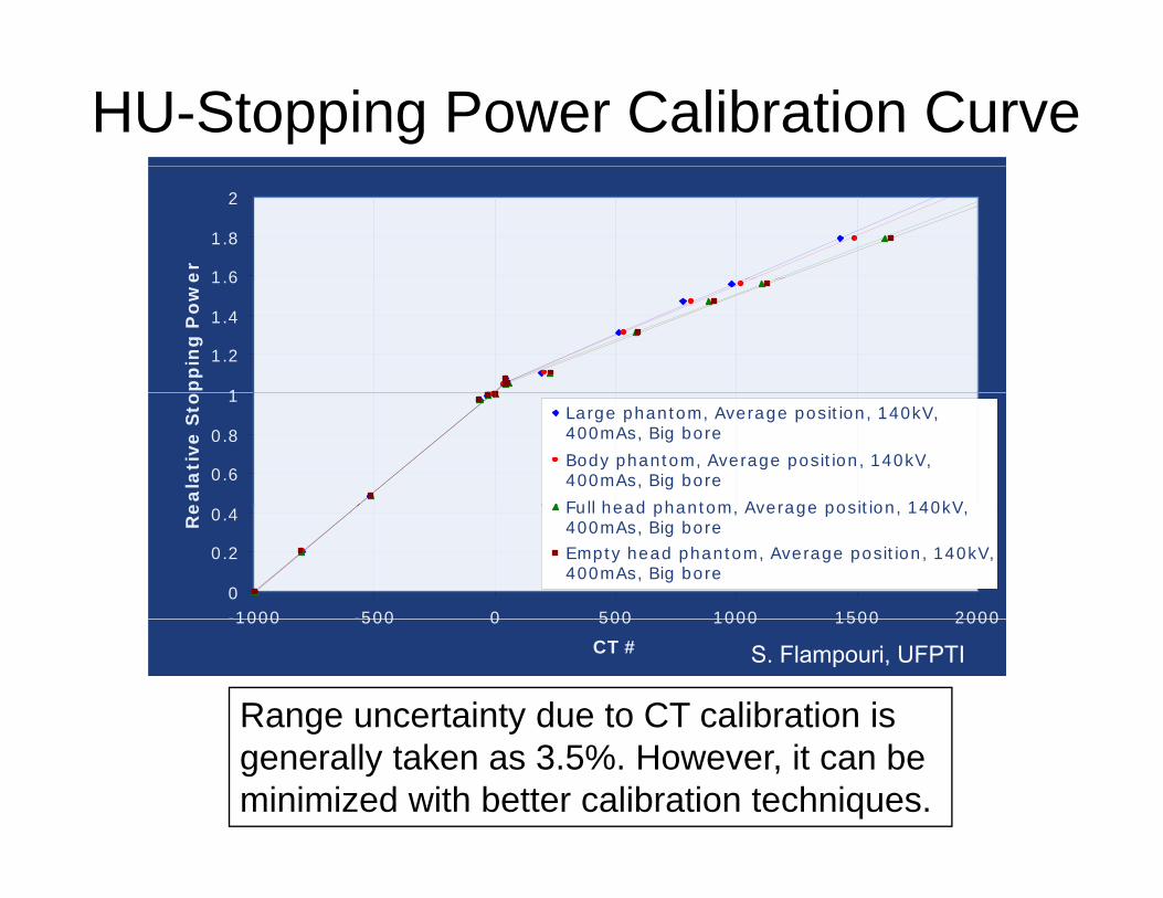
HU-Stopping Power Calibration Curve
1 6
1.8
2e
r
1
1.2
1.4
1.6
pp
ing
Po
we
0.6
0.8
1
ea
lati
ve
Sto Large phantom, Average position, 140kV,
400mAs, Big bore
Body phantom, Average position, 140kV,400mAs, Big bore
Full head phantom Average position 140kV
0
0.2
0.4
-1000 -500 0 500 1000 1500 2000
Re Full head phantom, Average position, 140kV,
400mAs, Big boreEmpty head phantom, Average position, 140kV,400mAs, Big bore
1000 500 0 500 1000 1500 2000
CT # S. Flampouri, UFPTI
Range uncertainty due to CT calibration is g ygenerally taken as 3.5%. However, it can be minimized with better calibration techniques.
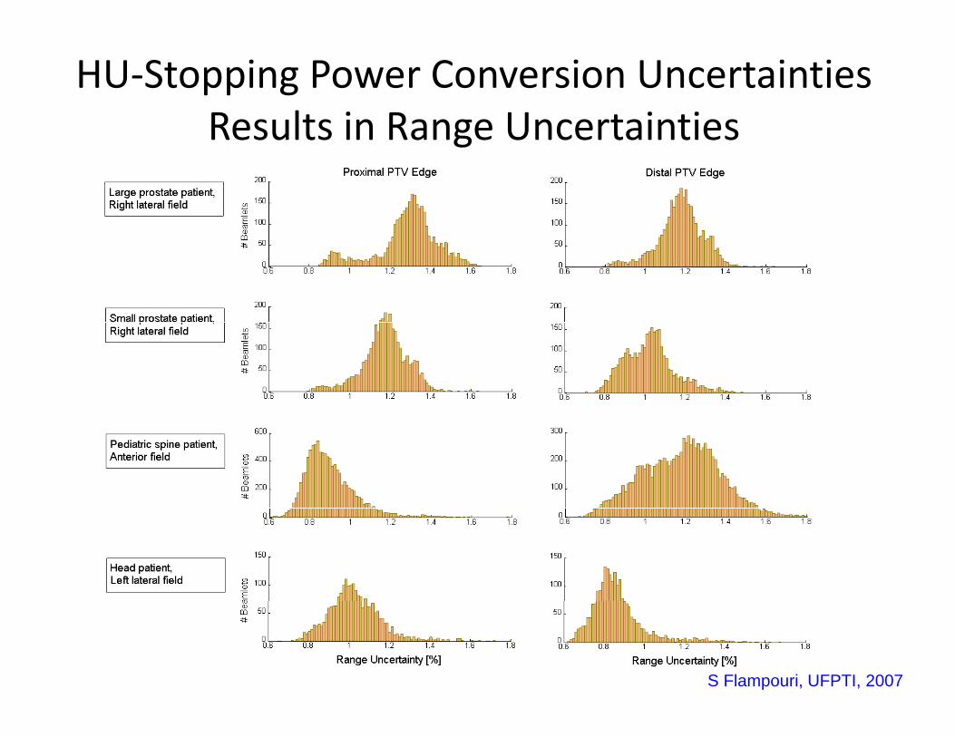
HU‐Stopping Power Conversion Uncertainties Results in Range UncertaintiesResults in Range Uncertainties
S Flampouri, UFPTI, 2007
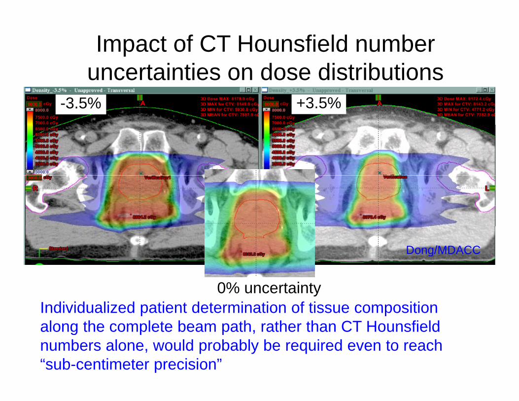
Impact of CT Hounsfield number uncertainties on dose distributionsuncertainties on dose distributions
-3.5% +3.5%
Dong/MDACC
0% uncertaintyIndividualized patient determination of tissue composition along the complete beam path rather than CT Hounsfieldalong the complete beam path, rather than CT Hounsfield numbers alone, would probably be required even to reach “sub-centimeter precision”
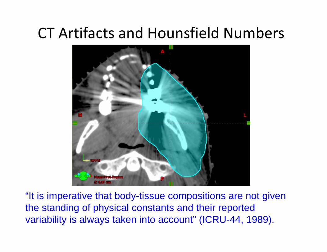
CT Artifacts and Hounsfield Numbers
“It is imperative that body-tissue compositions are not given th t di f h i l t t d th i t dthe standing of physical constants and their reported variability is always taken into account” (ICRU-44, 1989).
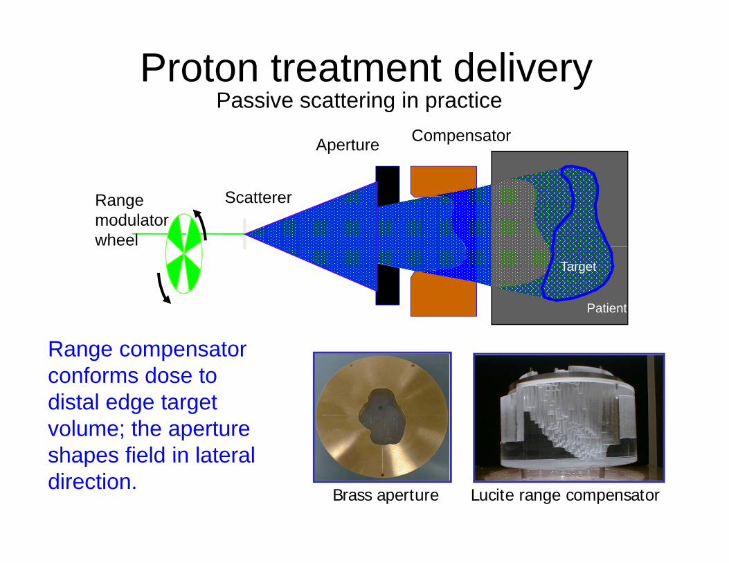
Proton treatment deliveryPassive scattering in practicePassive scattering in practice
Aperture Compensator
Range modulator wheel
Scatterer
Target
Patient
Range compensator conforms dose to distal edge target volume; the aperture shapes field in lateralshapes field in lateral direction.
Brass aperture Lucite range compensator
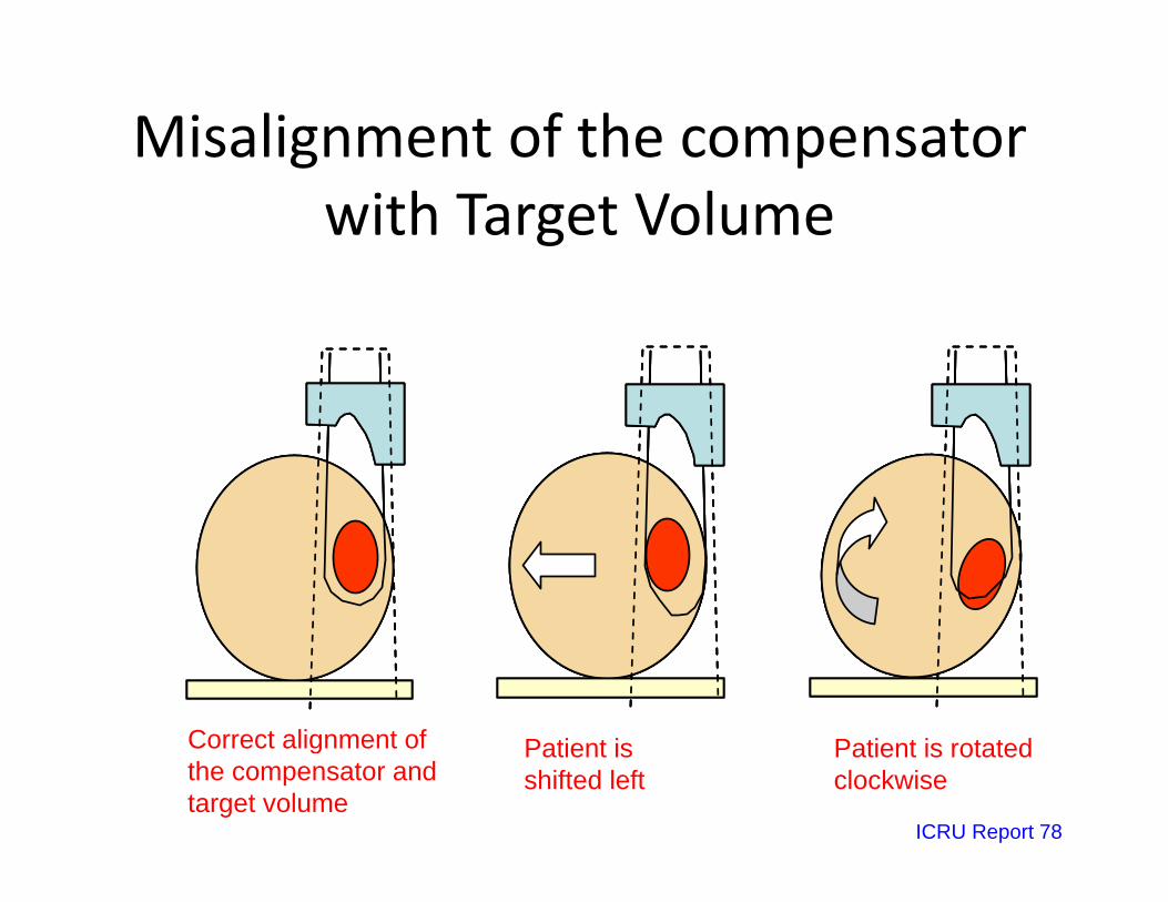
Misalignment of the compensator g pwith Target Volume
Correct alignment of (c)(b)(a) (c)(c)(b)(b)(a)(a)Correct alignment of the compensator and target volume
Patient is shifted left
Patient is rotated clockwise
ICRU Report 78
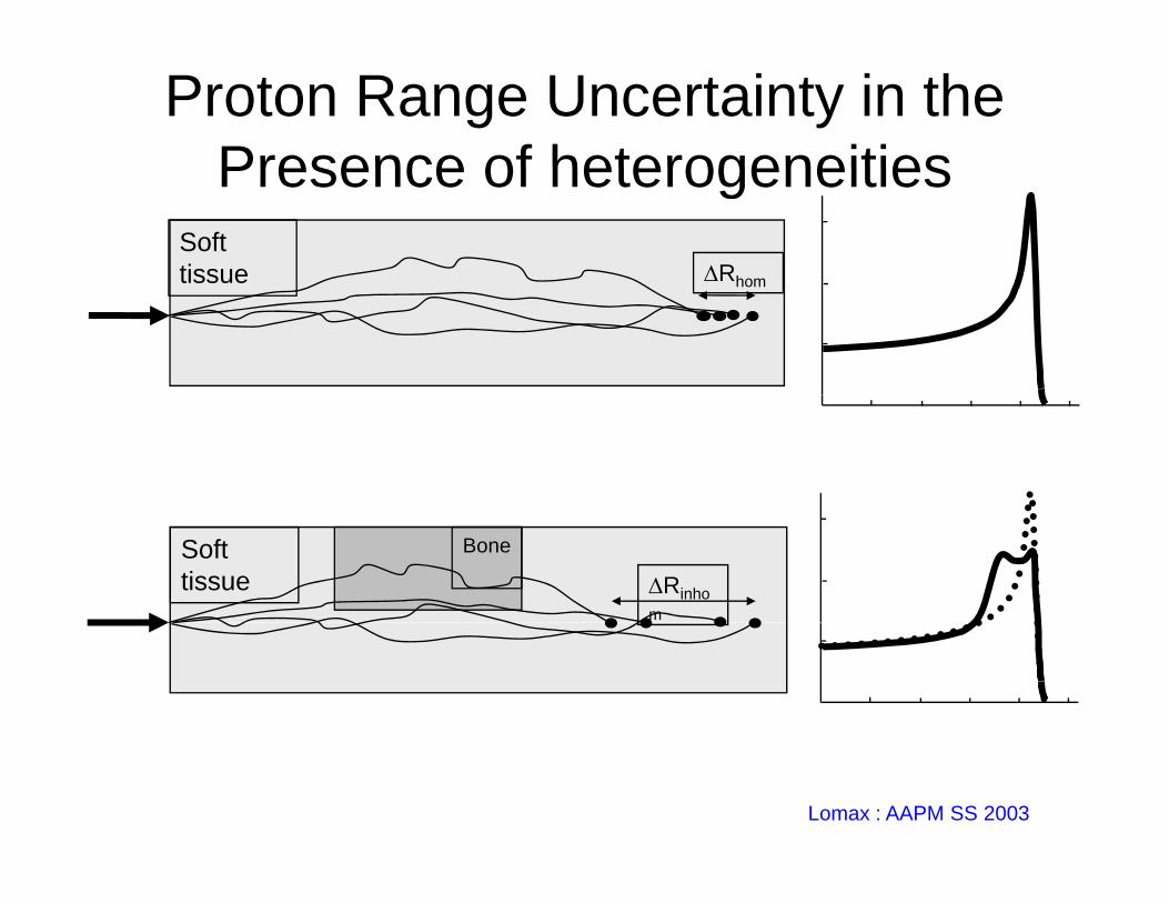
Proton Range Uncertainty in the Presence of heterogeneitiesPresence of heterogeneities
Soft tissue Rhomtissue Rhom
Soft tissue
Bone
Rinhom
Lomax : AAPM SS 2003
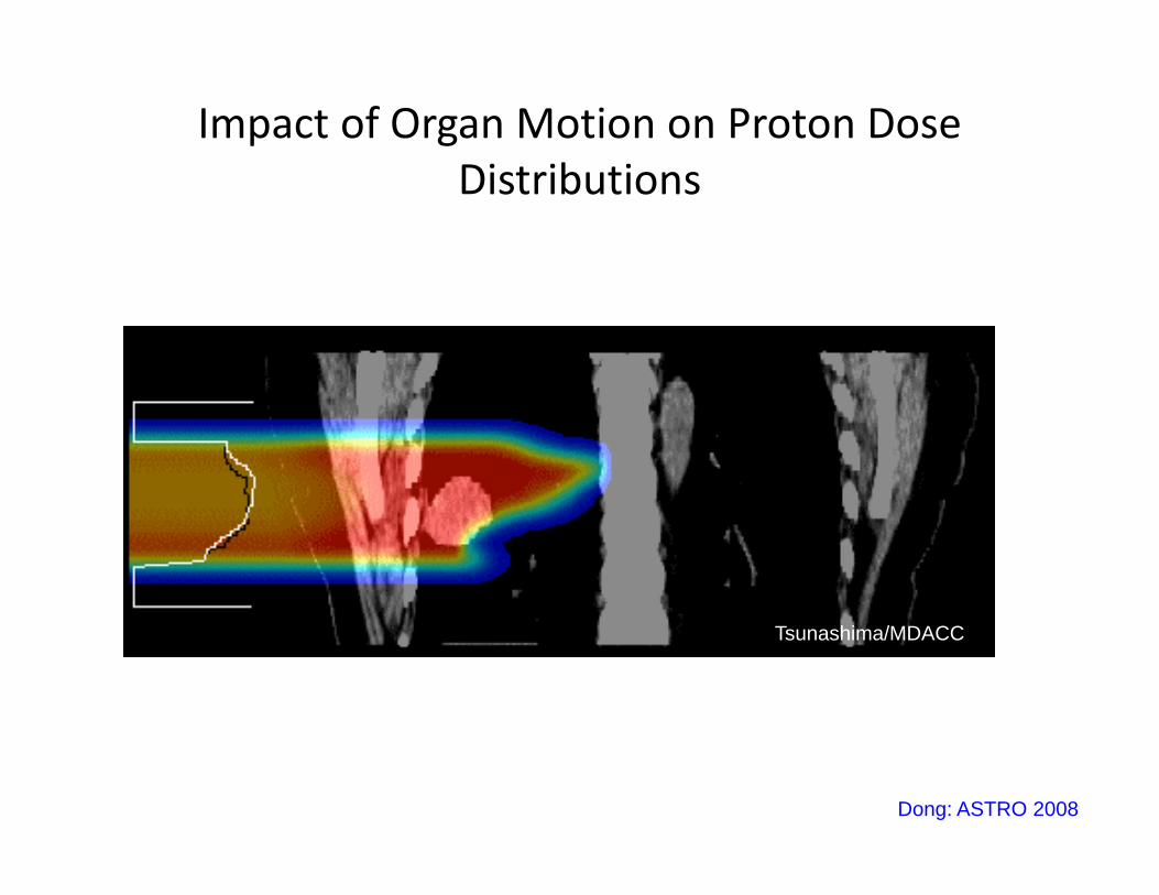
Impact of Organ Motion on Proton Dose Di ib iDistributions
Free breathing treatment
Tsunashima/MDACC
Dong: ASTRO 2008
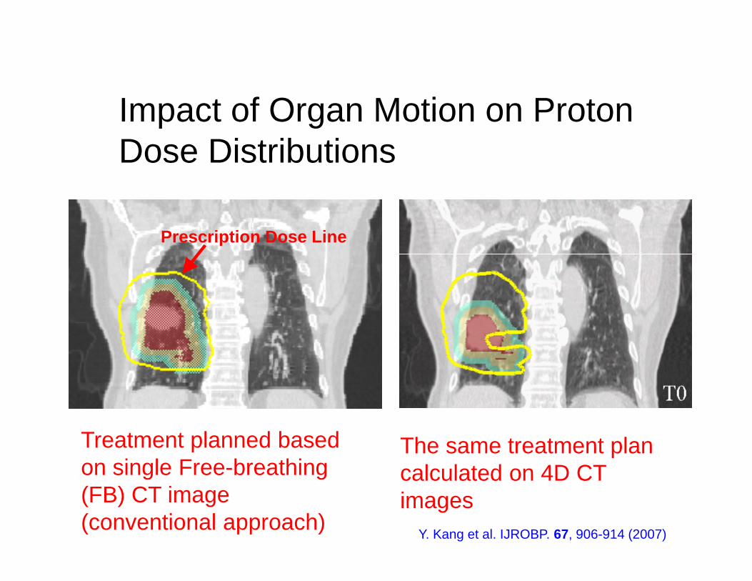
Impact of Organ Motion on ProtonImpact of Organ Motion on Proton Dose Distributions
Prescription Dose Line
Treatment planned based on single Free-breathing
The same treatment plan calculated on 4D CTon single Free breathing
(FB) CT image (conventional approach)
calculated on 4D CT images
Y. Kang et al. IJROBP. 67, 906-914 (2007)
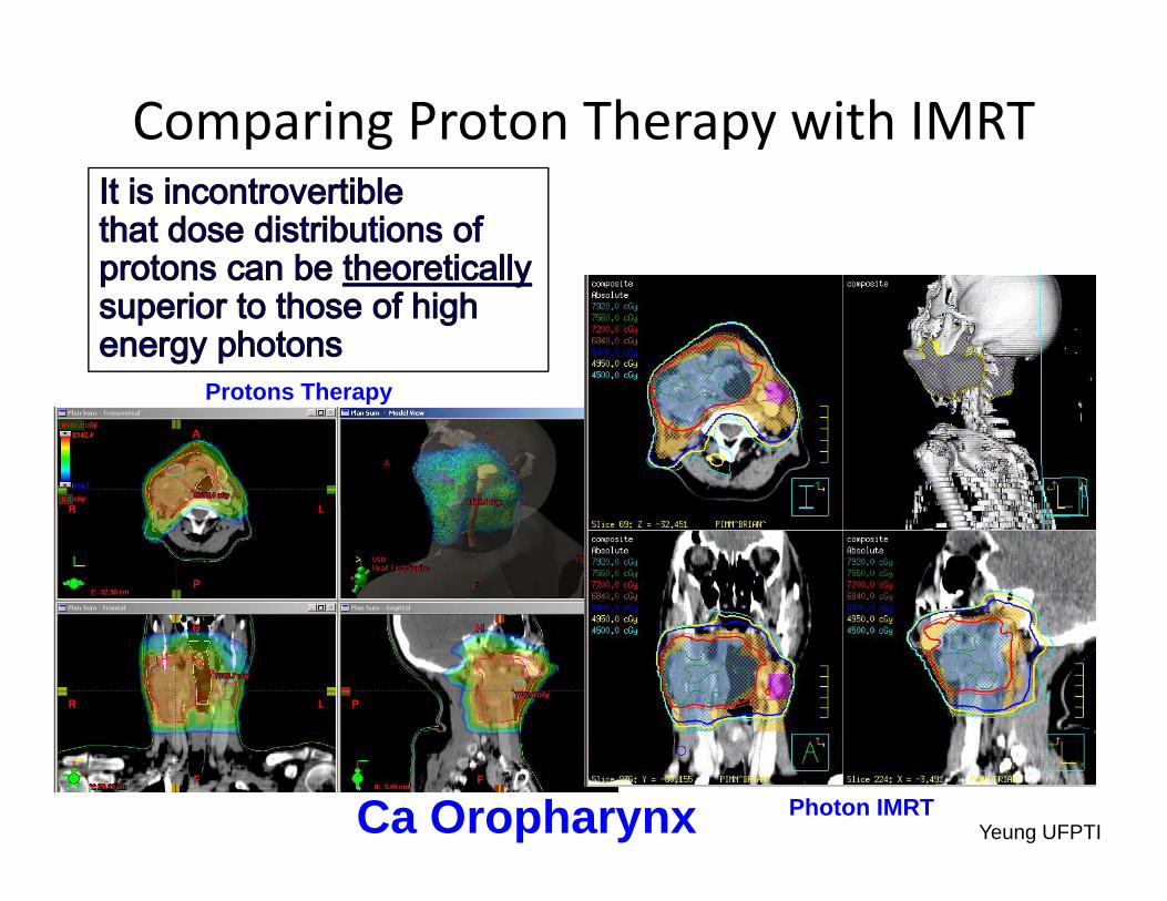
Comparing Proton Therapy with IMRT
Protons TherapyProtons Therapy
Ca Oropharynx Photon IMRTYeung UFPTI
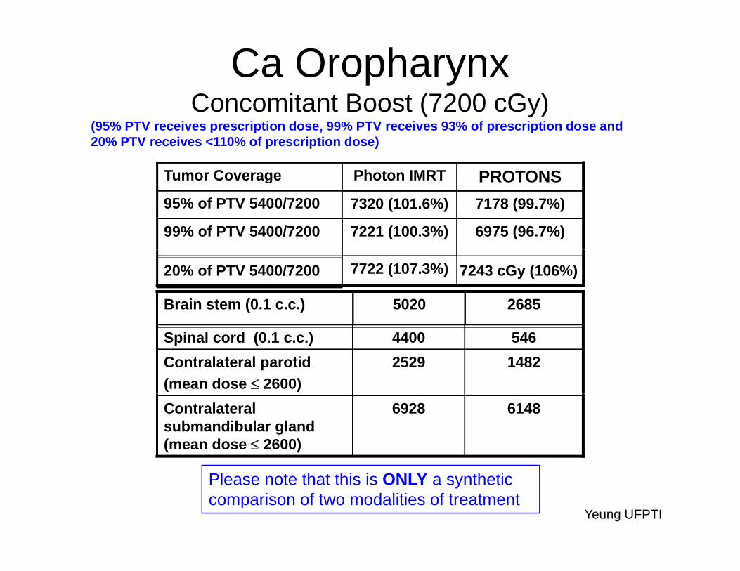
Ca Oropharynx Concomitant Boost (7200 cGy)
PROTONSPhoton IMRTTumor Coverage
Concomitant Boost (7200 cGy)(95% PTV receives prescription dose, 99% PTV receives 93% of prescription dose and 20% PTV receives <110% of prescription dose)
6975 (96.7%)7221 (100.3%)99% of PTV 5400/7200
7178 (99.7%)7320 (101.6%)95% of PTV 5400/7200
PROTONSPhoton IMRTTumor Coverage
7243 cGy (106%)7722 (107.3%)20% of PTV 5400/7200
26855020Brain stem (0.1 c.c.)
14822529Contralateral parotid(mean dose 2600)
5464400Spinal cord (0.1 c.c.)
61486928Contralateral submandibular gland (mean dose 2600)
Yeung UFPTI
Please note that this is ONLY a synthetic comparison of two modalities of treatment
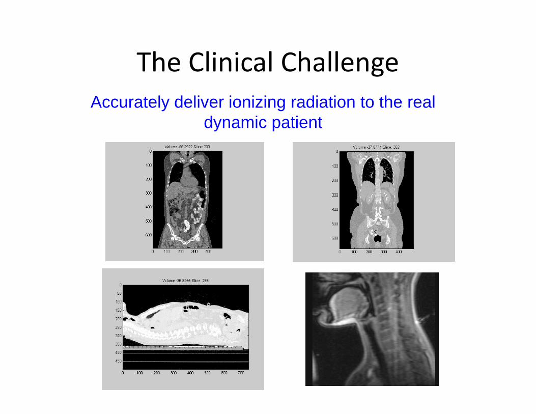
The Clinical ChallengegAccurately deliver ionizing radiation to the real
dynamic patienty p
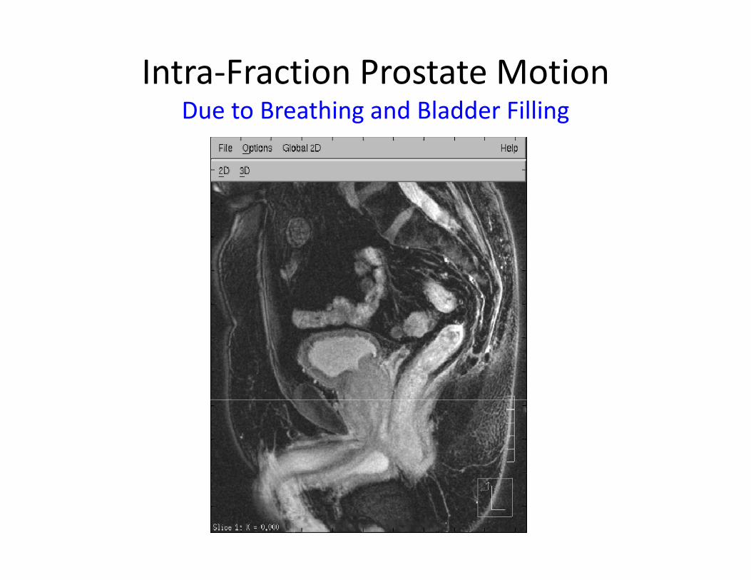
Intra‐Fraction Prostate Motion Due to Breathing and Bladder FillingDue to Breathing and Bladder Filling
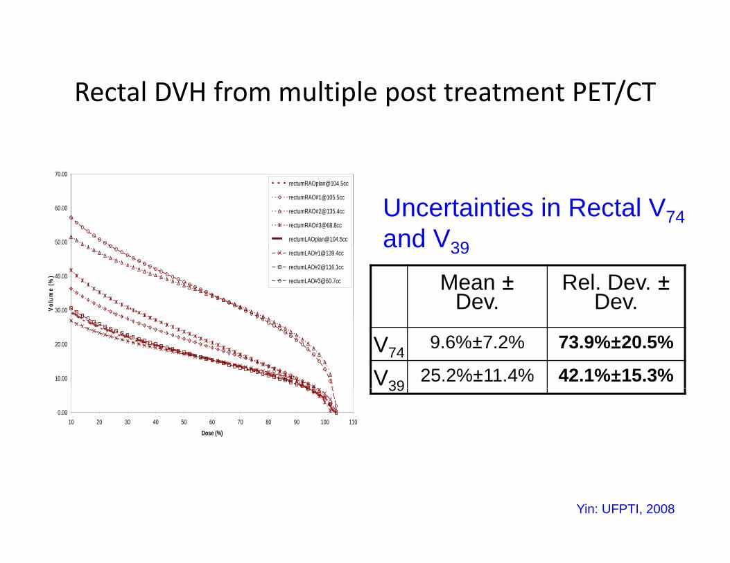
Rectal DVH from multiple post treatment PET/CTp p /
70 00
50.00
60.00
rectumRAO#[email protected]
rectumRAO#[email protected]
rectumRAO#[email protected]
Uncertainties in Rectal V74and V39
30.00
40.00
Volu
me
(%)
rectumLAO#[email protected]
rectumLAO#[email protected]
rectumLAO#[email protected]
and V39
Mean ±Dev.
Rel. Dev. ±Dev.
10.00
20.00 V74 9.6%±7.2% 73.9%±20.5%
V39 25.2%±11.4% 42.1%±15.3%
0.0010 20 30 40 50 60 70 80 90 100 110
Dose (%)
39
Yin: UFPTI, 2008
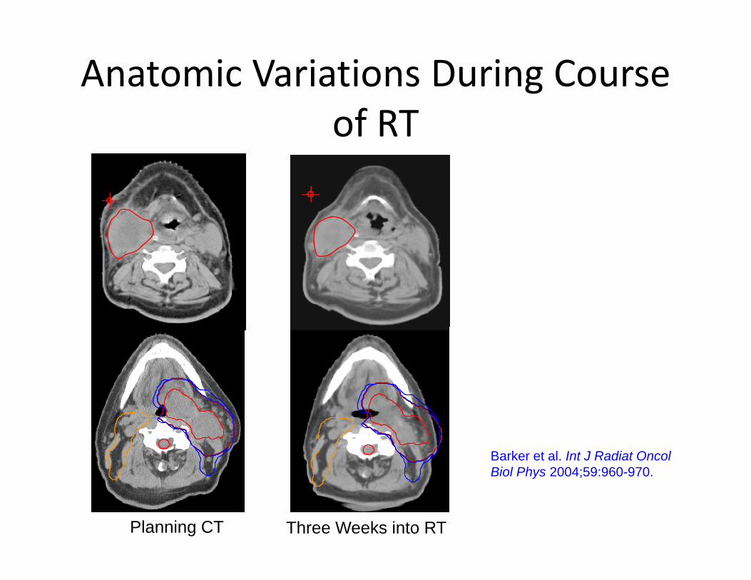
Anatomic Variations During Course of RT
Barker et al. Int J Radiat Oncol Biol Phys 2004;59:960-970Biol Phys 2004;59:960-970.
Planning CT Three Weeks into RT
D l l t d
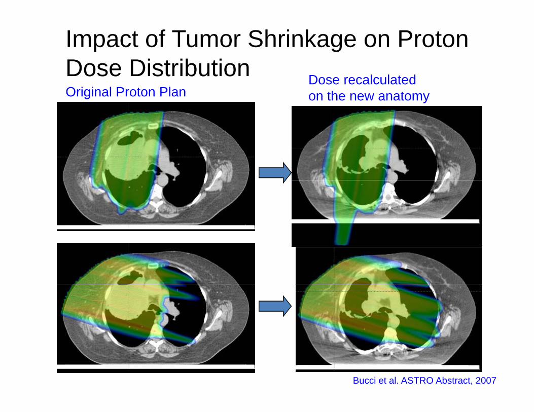
Impact of Tumor Shrinkage on Proton Dose DistributionOriginal Proton Plan
Dose recalculated on the new anatomy
ose st but o
Bucci et al. ASTRO Abstract, 2007

The three ‘orders’ of proton therapy compared
Intensity Modulated Proton Therapy (IMPT)
IMPTPassive scattering
Spot scanning
e t ee o de s o p oto t e apy co pa ed
1 field1 field 1 field
3 fields3 fields 3 fieldsLomax/PSI
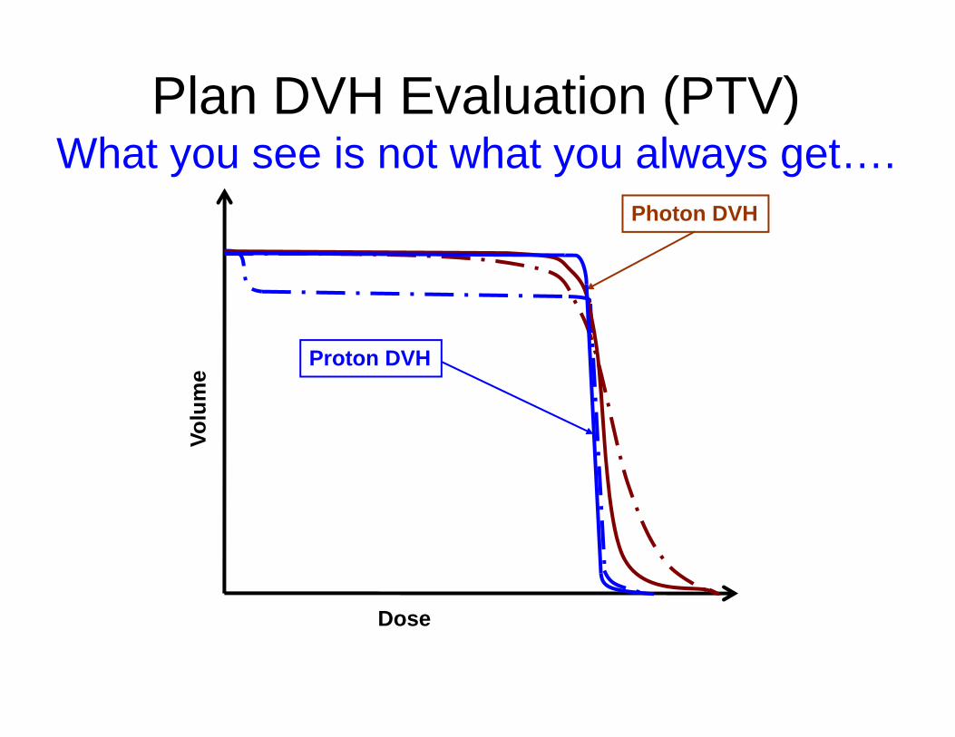
Plan DVH Evaluation (PTV)
Photon DVH
What you see is not what you always get….um
e
Proton DVH
Vol
Dose
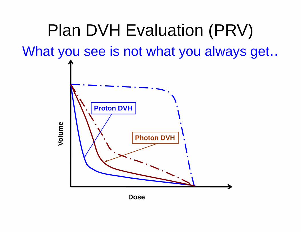
Plan DVH Evaluation (PRV)What you see is not what you always get..
me
Proton DVH
Volu
m
Photon DVH
Dose
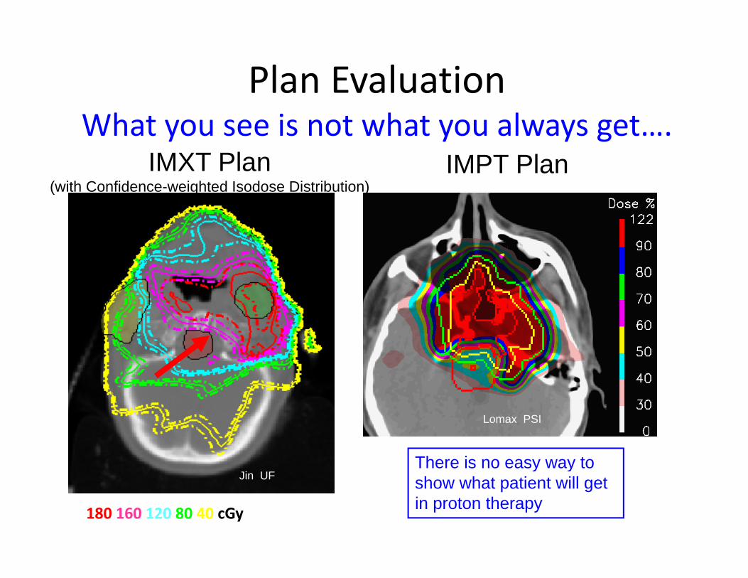
Plan EvaluationWhat you see is not what you always get….
IMXT Plan IMPT Plan(with Confidence-weighted Isodose Distribution)
Lomax PSI
Ji UFThere is no easy way to
180 160 120 80 40 cGy
Jin UFy y
show what patient will get in proton therapy
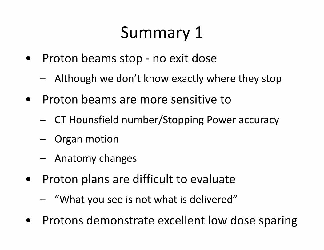
Summary 1• Proton beams stop ‐ no exit dose
Although we don’t know exactly where they stop– Although we don t know exactly where they stop
• Proton beams are more sensitive to
– CT Hounsfield number/Stopping Power accuracy
– Organ motionOrgan motion
– Anatomy changes
• Proton plans are difficult to evaluate
– “What you see is not what is delivered”y
• Protons demonstrate excellent low dose sparing
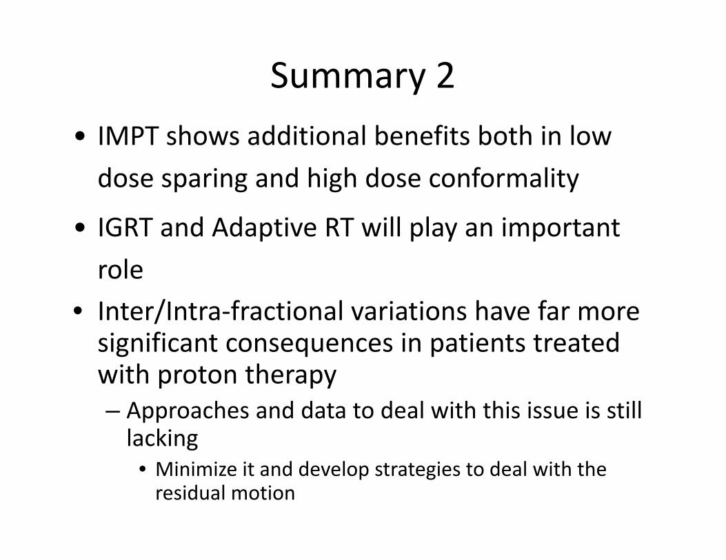
Summary 2• IMPT shows additional benefits both in low
dose sparing and high dose conformalitydose sparing and high dose conformality
• IGRT and Adaptive RT will play an important
role• Inter/Intra‐fractional variations have far moreInter/Intra fractional variations have far more significant consequences in patients treated with proton therapyp py– Approaches and data to deal with this issue is still lacking
• Minimize it and develop strategies to deal with the residual motion
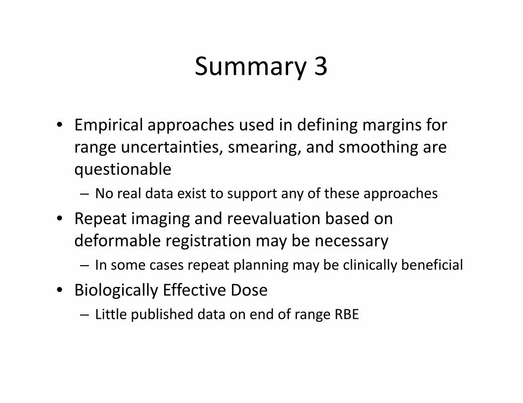
Summary 3Summary 3
• Empirical approaches used in defining margins for• Empirical approaches used in defining margins for range uncertainties, smearing, and smoothing are questionableq– No real data exist to support any of these approaches
• Repeat imaging and reevaluation based on p g gdeformable registration may be necessary– In some cases repeat planning may be clinically beneficial
• Biologically Effective Dose– Little published data on end of range RBE
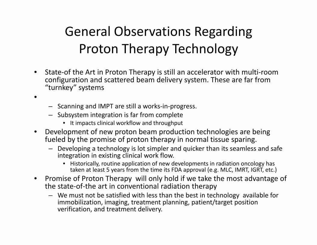
General Observations Regarding P t Th T h lProton Therapy Technology
• State‐of the Art in Proton Therapy is still an accelerator with multi‐room configuration and scattered beam delivery system. These are far from “turnkey” systems
•– Scanning and IMPT are still a works‐in‐progressScanning and IMPT are still a works in progress.– Subsystem integration is far from complete
• It impacts clinical workflow and throughput
• Development of new proton beam production technologies are being f l d b th i f t th i l ti ifueled by the promise of proton therapy in normal tissue sparing.– Developing a technology is lot simpler and quicker than its seamless and safe
integration in existing clinical work flow.• Historically, routine application of new developments in radiation oncology has
taken at least 5 years from the time its FDA approval (e g MLC IMRT IGRT etc )taken at least 5 years from the time its FDA approval (e.g. MLC, IMRT, IGRT, etc.)
• Promise of Proton Therapy will only hold if we take the most advantage of the state‐of‐the art in conventional radiation therapy– We must not be satisfied with less than the best in technology available for
i bili i i i l i i / i iimmobilization, imaging, treatment planning, patient/target position verification, and treatment delivery.