physics notes - anthemion.org · vdt in uniform motion, vis constant, so that: x 1 = x 0 + vtj t1...
TRANSCRIPT

Physics NotesJeremy Kelly
www.anthemion.org
October 31, 2017
These are my personal physics notes. They are not yet complete,
but eventually they will cover all the topics a first or second year
physics major would study. You are welcome to copy or distribute
them, subject to the terms of the Creative Commons Attribution-
ShareAlike 4.0 International License. To view this license, visit
http://creativecommons.org/licenses/by-sa/4.0/.
Contents
1 Newton’s laws of motion 21.1 Linear motion . . . . . . . . . . . . . . . . . 21.2 Motion on an inclined plane . . . . . . . . . 31.3 Force . . . . . . . . . . . . . . . . . . . . . . 31.4 Resistive forces . . . . . . . . . . . . . . . . 41.5 Planar motion . . . . . . . . . . . . . . . . . 51.6 Projectile motion . . . . . . . . . . . . . . . 51.7 Relative motion . . . . . . . . . . . . . . . . 61.8 Uniform circular motion . . . . . . . . . . . 61.9 Circular orbits . . . . . . . . . . . . . . . . 71.10 Non-uniform circular motion . . . . . . . . 81.11 Action and reaction . . . . . . . . . . . . . 8
2 Momentum 92.1 Conservation of momentum . . . . . . . . . 92.2 Rocket propulsion . . . . . . . . . . . . . . 10
3 Energy 103.1 Gravitational potential energy . . . . . . . . 103.2 Restoring forces . . . . . . . . . . . . . . . . 113.3 Elastic potential energy . . . . . . . . . . . 123.4 Elastic collisions . . . . . . . . . . . . . . . 123.5 Energy diagrams . . . . . . . . . . . . . . . 13
4 Work 144.1 Kinetic energy and work . . . . . . . . . . . 154.2 Potential energy and work . . . . . . . . . . 154.3 Thermal energy and work . . . . . . . . . . 164.4 Conservation of energy . . . . . . . . . . . . 164.5 Power . . . . . . . . . . . . . . . . . . . . . 16
5 Newton’s theory of gravity 165.1 Gravitational potential energy . . . . . . . . 175.2 Satellite orbits . . . . . . . . . . . . . . . . 175.3 Orbital energy . . . . . . . . . . . . . . . . 185.4 Gravitational fields . . . . . . . . . . . . . . 19
6 Rotation of rigid bodies 196.1 Center of mass . . . . . . . . . . . . . . . . 19
6.2 Torque . . . . . . . . . . . . . . . . . . . . . 206.3 Rotational dynamics . . . . . . . . . . . . . 216.4 Rotational energy . . . . . . . . . . . . . . . 226.5 Rolling motion . . . . . . . . . . . . . . . . 226.6 Angular momentum . . . . . . . . . . . . . 236.7 Precession . . . . . . . . . . . . . . . . . . . 24
7 Oscillation 247.1 Simple harmonic motion . . . . . . . . . . . 247.2 Energy of simple harmonic motion . . . . . 267.3 Pendulums . . . . . . . . . . . . . . . . . . 267.4 Damped oscillation . . . . . . . . . . . . . . 27
8 Fluids 288.1 Pressure . . . . . . . . . . . . . . . . . . . . 288.2 Hydraulics . . . . . . . . . . . . . . . . . . . 298.3 Buoyancy . . . . . . . . . . . . . . . . . . . 298.4 Fluid dynamics . . . . . . . . . . . . . . . . 30
9 Elasticity 31
10 Matter and temperature 3210.1 Temperature . . . . . . . . . . . . . . . . . 3210.2 Ideal gases . . . . . . . . . . . . . . . . . . . 3310.3 Ideal gas processes . . . . . . . . . . . . . . 34
11 First law of thermodynamics 3411.1 Ideal gas processes and work . . . . . . . . 3411.2 Heat . . . . . . . . . . . . . . . . . . . . . . 3511.3 Specific heat of gasses . . . . . . . . . . . . 3611.4 Adiabatic processes . . . . . . . . . . . . . . 36
12 Kinetic theory 3712.1 Mean free path . . . . . . . . . . . . . . . . 3712.2 Gas pressure . . . . . . . . . . . . . . . . . 3812.3 Gas temperature . . . . . . . . . . . . . . . 3912.4 Thermal energy and specific heat . . . . . . 3912.5 Second law of thermodynamics . . . . . . . 40
13 Heat engines and refrigerators 4013.1 Brayton cycle . . . . . . . . . . . . . . . . . 4213.2 Otto cycle . . . . . . . . . . . . . . . . . . . 4313.3 Diesel cycle . . . . . . . . . . . . . . . . . . 4413.4 Carnot cycle . . . . . . . . . . . . . . . . . . 44
14 Waves 4514.1 Sinusoidal waves . . . . . . . . . . . . . . . 4614.2 Wave speed in strings . . . . . . . . . . . . 4714.3 Speed of sound . . . . . . . . . . . . . . . . 4814.4 Wave power and intensity . . . . . . . . . . 4914.5 Impedance . . . . . . . . . . . . . . . . . . . 5014.6 Light . . . . . . . . . . . . . . . . . . . . . . 5314.7 Doppler Effect . . . . . . . . . . . . . . . . 5314.8 Standing waves . . . . . . . . . . . . . . . . 5414.9 Interference . . . . . . . . . . . . . . . . . . 55
1

1 NEWTON’S LAWS OF MOTION 2
15 Wave optics 5615.1 Double-slit experiment . . . . . . . . . . . . 5615.2 Diffraction gratings . . . . . . . . . . . . . . 5715.3 Single-slit diffraction . . . . . . . . . . . . . 5815.4 Interferometry . . . . . . . . . . . . . . . . 59
16 Ray optics 6016.1 Reflection . . . . . . . . . . . . . . . . . . . 6016.2 Refraction . . . . . . . . . . . . . . . . . . . 6116.3 Total internal reflection . . . . . . . . . . . 6216.4 Scattering . . . . . . . . . . . . . . . . . . . 6316.5 Thin lenses . . . . . . . . . . . . . . . . . . 6316.6 Spherical lenses . . . . . . . . . . . . . . . . 6516.7 Resolution . . . . . . . . . . . . . . . . . . . 67
17 Wave-particle duality and quantization 6717.1 Spectroscopy . . . . . . . . . . . . . . . . . 6717.2 X-ray diffraction . . . . . . . . . . . . . . . 6817.3 Photon model of light . . . . . . . . . . . . 6817.4 Matter waves . . . . . . . . . . . . . . . . . 69
18 Electric charge 6918.1 Coulomb’s law . . . . . . . . . . . . . . . . 7018.2 Electric fields . . . . . . . . . . . . . . . . . 7118.3 Uniform charge distributions . . . . . . . . 7218.4 Motion of charged objects . . . . . . . . . . 74
19 Gauss’ law 7519.1 Symmetric charge distributions . . . . . . . 7619.2 Conductors in electrostatic equilibrium . . . 77
A Measurement 77
B Vectors 78B.1 Dot products . . . . . . . . . . . . . . . . . 78B.2 Cross products . . . . . . . . . . . . . . . . 78
Sources 79
1 Newton’s laws of motion
1.1 Linear motion
A trajectory is a path along which some object moves.Motion within a trajectory is called translational mo-tion.
Speed is a scalar quantity equal to the magnitude of thevelocity. Positive acceleration entails increasing speed onlyif the velocity is currently positive in direction. A turn-ing point is a place where some quantity, such as velocity,changes sign.
In a single dimension, vector quantities like ~v can be repre-sented with scalars, like v. When this is done, the positionafter a displacement at velocity v:
x1 = x0 +
∫ t1
t0
v dt
In uniform motion, v is constant, so that:
x1 = x0 + vt|t1t0= x0 + v(t1 − t0)
= x0 + v∆t
In general, the delta symbol is understood to referencethe time spanned by an event, so that ∆t = t1 − t0 and∆x = x1 − x0.
Given a graph of position over time, the slope of the lineconnecting two points gives the average velocity betweenthem, equal to v = ∆x/∆t. The slope of the tangent to anypoint gives the instantaneous velocity:
v ≡ lim∆t→0
∆x
∆t=
dx
dt
Given a graph of velocity over time, the slope of the lineconnecting two points gives the average acceleration be-tween them, equal to a = ∆v/∆t. The slope of the tangentto any point gives the instantaneous acceleration:
a ≡ lim∆t→0
∆v
∆t=
dv
dt=
d2x
dt2
The velocity after a period of acceleration:
v1 = v0 +
∫ t1
t0
a dt
Assuming uniformly accelerated motion:
v1 = v0 + a∆t
so that:
x1 = x0 +
∫ t1
t0
v dt
= x0 +
∫ t1
t0
v0 + a(t− t0) dt
Notice that the velocity function is v0 + a(t − t0) ratherthan v0 +at. By definition, the time is t0 when the velocityis v0, so any change relative to v0 must relate to a changerelative to the time at the same point. This produces:
x1 = x0 +[v0t+
1
2at2 − at0t
]t1t0
1 NEWTON’S LAWS OF MOTION 3
= x0 + v0∆t+1
2at21 −
1
2at20 − at0t1 + at20
= x0 + v0∆t+1
2a(t21 − 2t0t1 + t20
)Finally, since:
(t1 − t0)2 = t21 − 2t0t1 + t20
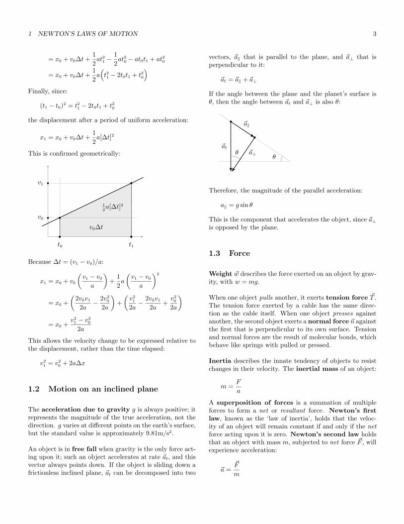
the displacement after a period of uniform acceleration:
x1 = x0 + v0∆t+1
2a[∆t]2
This is confirmed geometrically:
t0 t1
v1
v0
v0∆t
12a[∆t]2
Because ∆t = (v1 − v0)/a:
x1 = x0 + v0
(v1 − v0
a
)+
1
2a
(v1 − v0
a
)2
= x0 +
(2v0v1
2a− 2v2
0
2a
)+
(v2
1
2a− 2v0v1
2a+v2
0
2a
)
= x0 +v2
1 − v20
2a
This allows the velocity change to be expressed relative tothe displacement, rather than the time elapsed:
v21 = v2
0 + 2a∆x
1.2 Motion on an inclined plane
The acceleration due to gravity g is always positive; itrepresents the magnitude of the true acceleration, not thedirection. g varies at different points on the earth’s surface,but the standard value is approximately 9.81m/s2.
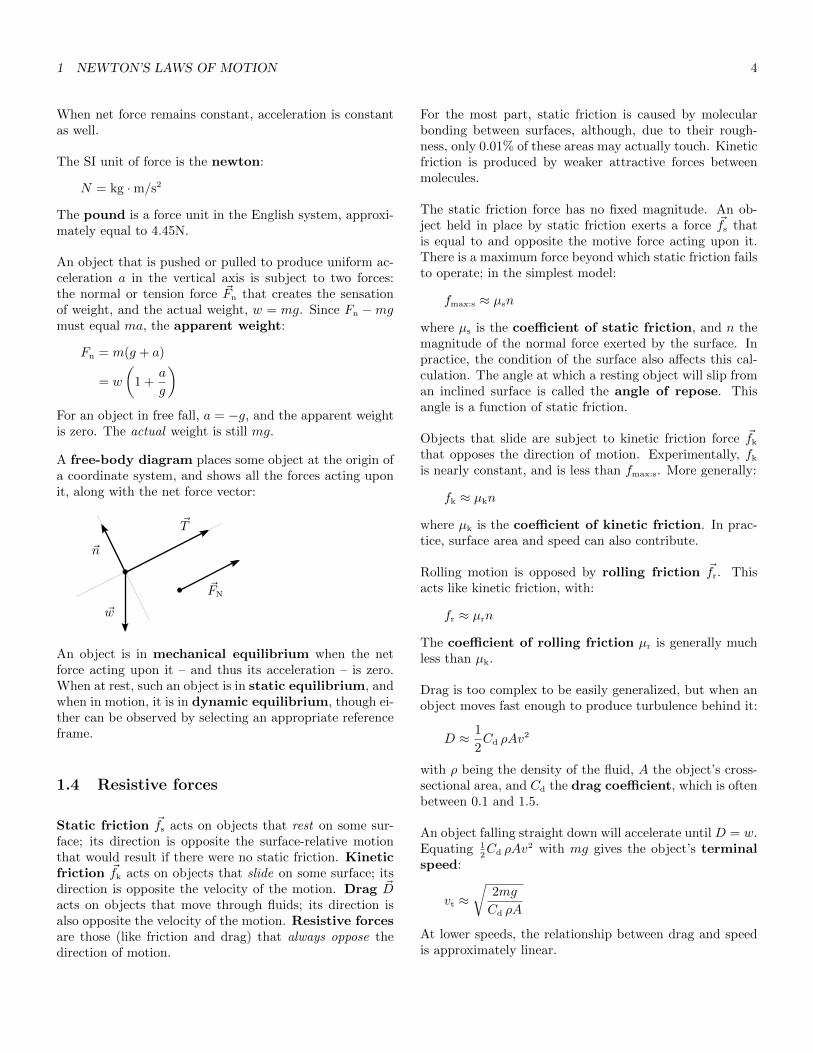
An object is in free fall when gravity is the only force act-ing upon it; such an object accelerates at rate ~af , and thisvector always points down. If the object is sliding down africtionless inclined plane, ~af can be decomposed into two
vectors, ~a‖ that is parallel to the plane, and ~a⊥ that isperpendicular to it:
~af = ~a‖ + ~a⊥
If the angle between the plane and the planet’s surface isθ, then the angle between ~af and ~a⊥ is also θ:
~a‖
~a⊥~af
θθ
Therefore, the magnitude of the parallel acceleration:
a‖ = g sin θ
This is the component that accelerates the object, since ~a⊥is opposed by the plane.
1.3 Force
Weight ~w describes the force exerted on an object by grav-ity, with w = mg.
When one object pulls another, it exerts tension force ~T .The tension force exerted by a cable has the same direc-tion as the cable itself. When one object presses againstanother, the second object exerts a normal force ~n againstthe first that is perpendicular to its own surface. Tensionand normal forces are the result of molecular bonds, whichbehave like springs with pulled or pressed.
Inertia describes the innate tendency of objects to resistchanges in their velocity. The inertial mass of an object:
m =F
a
A superposition of forces is a summation of multipleforces to form a net or resultant force. Newton’s firstlaw, known as the ‘law of inertia’, holds that the veloc-ity of an object will remain constant if and only if the netforce acting upon it is zero. Newton’s second law holdsthat an object with mass m, subjected to net force ~F , willexperience acceleration:
~a =~F
m
1 NEWTON’S LAWS OF MOTION 4
When net force remains constant, acceleration is constantas well.
The SI unit of force is the newton:
N = kg ·m/s2
The pound is a force unit in the English system, approxi-mately equal to 4.45N.
An object that is pushed or pulled to produce uniform ac-celeration a in the vertical axis is subject to two forces:the normal or tension force ~Fn that creates the sensationof weight, and the actual weight, w = mg. Since Fn −mgmust equal ma, the apparent weight:
Fn = m(g + a)
= w
(1 +
a
g
)For an object in free fall, a = −g, and the apparent weightis zero. The actual weight is still mg.
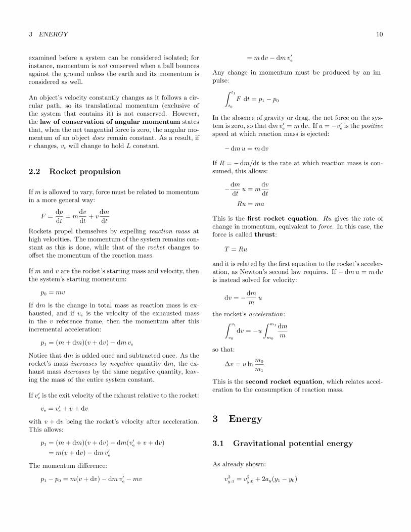
A free-body diagram places some object at the origin ofa coordinate system, and shows all the forces acting uponit, along with the net force vector:
~w
~n
~T
~FN
An object is in mechanical equilibrium when the netforce acting upon it – and thus its acceleration – is zero.When at rest, such an object is in static equilibrium, andwhen in motion, it is in dynamic equilibrium, though ei-ther can be observed by selecting an appropriate referenceframe.
1.4 Resistive forces
Static friction ~fs acts on objects that rest on some sur-face; its direction is opposite the surface-relative motionthat would result if there were no static friction. Kineticfriction ~fk acts on objects that slide on some surface; itsdirection is opposite the velocity of the motion. Drag ~Dacts on objects that move through fluids; its direction isalso opposite the velocity of the motion. Resistive forcesare those (like friction and drag) that always oppose thedirection of motion.
For the most part, static friction is caused by molecularbonding between surfaces, although, due to their rough-ness, only 0.01% of these areas may actually touch. Kineticfriction is produced by weaker attractive forces betweenmolecules.
The static friction force has no fixed magnitude. An ob-ject held in place by static friction exerts a force ~fs thatis equal to and opposite the motive force acting upon it.There is a maximum force beyond which static friction failsto operate; in the simplest model:
fmax:s ≈ µsn
where µs is the coefficient of static friction, and n themagnitude of the normal force exerted by the surface. Inpractice, the condition of the surface also affects this cal-culation. The angle at which a resting object will slip froman inclined surface is called the angle of repose. Thisangle is a function of static friction.
Objects that slide are subject to kinetic friction force ~fk
that opposes the direction of motion. Experimentally, fk
is nearly constant, and is less than fmax:s. More generally:
fk ≈ µkn
where µk is the coefficient of kinetic friction. In prac-tice, surface area and speed can also contribute.
Rolling motion is opposed by rolling friction ~fr. Thisacts like kinetic friction, with:
fr ≈ µrn
The coefficient of rolling friction µr is generally muchless than µk.
Drag is too complex to be easily generalized, but when anobject moves fast enough to produce turbulence behind it:
D ≈ 1
2Cd ρAv
2
with ρ being the density of the fluid, A the object’s cross-sectional area, and Cd the drag coefficient, which is oftenbetween 0.1 and 1.5.
An object falling straight down will accelerate until D = w.Equating 1
2Cd ρAv
2 with mg gives the object’s terminalspeed:
vt ≈√
2mg
Cd ρA
At lower speeds, the relationship between drag and speedis approximately linear.

1 NEWTON’S LAWS OF MOTION 5
1.5 Planar motion
A position vector is drawn from the origin to some posi-tion in space:
~r = xı+ y
A change in position is shown by the displacement, whichis drawn from the start position to the end position:
∆~r = ~r1 − ~r0 = ∆xı+ ∆y
A displacement is not a distance; it is a vector quantity,like velocity or acceleration, and its direction is significant.
A motion diagram shows the position of an object atequally spaced points in time, with velocity vectors con-necting each point with the next. Because they cover in-tervals of time, the velocity vectors are necessarily aver-ages. Where possible, the acceleration vector representingthe difference between ~vn and ~vn+1 is shown to emanatefrom the point joining ~vn and ~vn+1. Points showing noacceleration are labeled with the zero vector ~0:
~0~v
~v
~v
~v
~a
~a
The average velocity ∆~r/∆t necessarily points in the samedirection as ∆~r. Similarly, the average acceleration ∆~v/∆tpoints in the same direction as ∆~v.
The instantaneous velocity:
~v ≡ lim∆t→0
∆~r
∆t=
d~r
dt=
dx
dtı+
dy
dt
= vx ı+ vy
As ∆t → 0, ∆~r becomes tangent with the trajectory. If ~vhas angle θ relative to the positive x-axis, then vx = v cos θ,vy = v sin θ, and θ = arctan(vy/vx).
Similarly:
~a ≡ lim∆t→0
∆~v
∆t=
d~v
dt=
dvxdt
ı+dvydt
= ax ı+ ay
Acceleration can also be decomposed such that ~a = ~a‖+~a⊥,with component ~a‖ parallel to ~v, and ~a⊥ perpendicular toit; ~a‖ then gives the change in speed, and ~a⊥ the change in
direction. This causes the coordinate system to change as~v changes direction.
Planar motion can be modeled by decomposing ~a into ~axand ~ay, and then applying the linear motion model in bothdimensions.
1.6 Projectile motion
When an object moves in the horizontal and vertical axeswhile subject to no force but gravity, projectile motionis produced. Any object with constant, non-zero accelera-tion along one axis and none along the other will follow aparabolic trajectory.
Given projectile motion with initial velocity ~v0 and launchangle θ:
vx:0 = v0 cos θ
vy:0 = v0 sin θ
The only acceleration ay = −g. Therefore:
∆x = (v0 cos θ)∆t
∆y = (v0 sin θ)∆t− 1
2g[∆t]2
If the projectile lands at the same height it was launched,∆y = 0, and:
0 = ∆t(v0 sin θ − 1
2g∆t)
This equation has two roots, with the zero root represent-ing the launch time displacement, and the other that of thelanding time. Solving for the second of these:
∆t =2v0
gsin θ
Multiplying by vx:0 = v0 cos θ gives the horizontal displace-ment. Because 2 sin θ cos θ = sin 2θ:
∆x =v2
0
gsin 2θ
The distance is maximized when θ is 45°. Becausesin(180° − 2θ) = sin 2θ, launch angles of θ and (90° − θ)produce the same distances for 0 ≤ θ ≤ 90°.
The trajectory is found by calculating the component po-sitions with respect to time, and then substituting one so-lution into the other to eliminate the time variable:
∆y = (tan θ)∆x−( g
2v20 cos2 θ
)[∆x]2

1 NEWTON’S LAWS OF MOTION 6
1.7 Relative motion
An inertial reference frame is a coordinate systemwithin which Newton’s first and second laws hold. A refer-ence frame defined relative to a point that is acceleratingis not inertial, as free objects will accelerate spontaneouslyin the opposite direction. In this sense, the earth is not atrue inertial frame, since it accelerates around the sun.
If inertial frames S and S′ have comparable coordinate sys-tems, and if ~R is the position of the second origin relative tothe first, displacement vectors referencing the same pointare related by:
~r = ~r ′ + ~R
S
S′
~r ~r ′
~R
y
x
y′
x′
If S′ moves relative to S at velocity ~V , and if they meetwhen t = 0, then ~R = ~V t, and:
~r = ~r ′ + ~V t
This is known as the Galilean transformation of posi-tion. It follows that:
x = x′ + Vxt
y = y′ + Vyt
Since the horizontal velocity component in projectile mo-tion is constant, projectile motion can be understood asfree fall motion viewed from a different reference frame,and vice versa.
If the point referenced by ~r and ~r ′ also moves:
d~r
dt=
d~r ′
dt+
d~R
dt
which gives the Galilean transformation of velocity:
~v = ~v ′ + ~V
Similarly:
d~v
dt=
d~v ′
dt+
d~V
dt
However, the relative acceleration of inertial referenceframes is defined to be zero:
~A =d~V
dt= 0
This gives the Galilean transformation of accelera-tion:
~a = ~a ′
Neither the mass of an object nor the force exerted uponit change when observed from different frames. Thus theGalilean principle of relativity, which states that New-ton’s laws, applying to phenomena viewed from one iner-tial reference frame, still hold when the same phenomenaare viewed from any such frame. By contrast, the speedof a given ray of light is identical in all reference frames,no matter what their relative velocity. This produces theprinciples of special relativity.
1.8 Uniform circular motion
Constant-speed motion in a circular path is called uniformcircular motion. The period T of a circular motion isthe time required to complete one revolution. Given radiusr, dividing the circumference by the period produces thespeed of the motion:
v =2πr
T
The angular position θ of some point is the angle be-tween the positive x-axis and the line segment connectingthat point with the origin. The difference between two suchangles is the angular displacement.
In a circle with radius r, each radian of angular displace-ment spans an arc of length r. More generally, when θ ismeasured in radians, the arc length:
s = θr
The angular velocity:
ω ≡ lim∆t→0
∆θ
∆t=
dθ
dt
gives the rate at which the angle changes, in radians perunit of time, with positive values representing counterclock-wise motion. Because there are 2π radians in each revolu-tion, and because the period cannot be negative:
|ω| = 2π
TT =
2π
|ω|

1 NEWTON’S LAWS OF MOTION 7
The properties of an object in circular motion can be de-scribed with the rtz coordinate system, with the radialaxis r projecting from the object toward the circle’s center,the tangential axis t tangent to the circle and projectingin the counterclockwise direction, and the perpendicularaxis z perpendicular to the plane of motion. Given vector~A in the plane of motion, with angle φ between the vectorand the r-axis:
φ
~A
~At
~Ar
~Ar and ~At form a right angle at the vector’s starting point,and ~A divides that angle, so that the vector’s radial andtangential components:
Ar = A cosφ
At = A sinφ
Conversely:
A =√A2r +A2
t
φ = arctan(AtAr
)The velocity components vr and vz of an object in circularmotion are zero, while the tangential velocity vt shows therate at which the object travels the circle. Given arc lengths and angular displacement θ, in radians:
vt =ds
dt=
dθ
dtr = ωr
Though its speed never changes, an object in uniform cir-cular motion experiences constant centripetal acceler-ation. With each interval ∆t, assuming average velocity~v for that interval, the circle’s center combines with theendpoints of displacement ∆~r = ~v∆t to form an isosce-les triangle. The equal sides of this triangle have length rand interior angle θ. When two such intervals pass, andthe beginning of ∆~r0 is aligned with the beginning of ∆~r1,a similar triangle is formed, the base of which gives thedifference between ∆~r0 and ∆~r1:
θ
θ
αα
∆~r0
∆~r0
∆~r1 ∆~v∆t
r
α
so that:
∆~r1 −∆~r0 = ~v1∆t− ~v0∆t = ∆~v∆t
Because the sides of similar triangles have equal ratios:
|∆~v∆t|v∆t
=v∆t
r
which allows:
ar =|∆~v|∆t
=v2
r= ω2r
with ~ar pointing at all times toward the center. For a par-ticular v, ar appears to decrease with r when expressed asv2/r, and to increase with r when expressed as ω2r, but infact it always increases. This is because v = ωr.
To maintain the uniform circular motion, the forces on ther-axis must sum to mar, while those on the other axes mustsum to zero.
Centrifugal force is the fictitious force that seems to pullobjects away from the center of motion. In fact, it is simplya manifestation of inertia, and a demonstration that accel-erating points cannot be used to define inertial referenceframes.
When solving circular motion problems, it is necessary toremember forces like gravity and friction that may not seemrelevant at first. Be sure that the elements creating thecentripetal force are actually in the plane of motion.
1.9 Circular orbits
When the initial velocity of a projectile is sufficiently large,the earth’s curvature can no longer be ignored, as the sur-face will curve away from the projectile as it moves later-ally. The centripetal acceleration of an object in a perfectlycircular orbit is proportional to the force of gravity at the

1 NEWTON’S LAWS OF MOTION 8
orbital radius. At the earth’s surface, given orbital speedvo:
ar =v2
o
r=w
m= g
This necessitates that:
vo =√rg
Though vo appears to increase as r increases, g decreaseswith the square of r, so that vo decreases as well. Becausethe earth’s radius is almost 6400 km, and because low Earthorbits can be as near as 160 km, the surface value of g cansometimes provide a reasonable approximation.
Since T = 2πr/v, the period of a circular orbit:
To = 2π√r/g
A satellite in orbit at 160 km has a speed near 28, 800km/h, and a period of approximately 88 minutes. Like anyfalling object, an orbiting body experiences free fall.
1.10 Non-uniform circular motion
An object coasting or swinging through a circular motionin the vertical plane is subject to two forces: the force ofgravity, and a normal or tension force Fr that pushes orpulls it toward the center. This normal force depends onthe object’s velocity. Since the motion is circular, it is al-ways true that Fr = mv2
t /r, and, at the bottom, it alsotrue that Fr = n−w. n must exceed w if the motion is tocontinue, so the apparent weight at the bottom is greaterthan w.
At the top of the circle, Fr = n+w. Both n and Fr increasewith v, becoming arbitrarily large as long as the track orcable does not break. Since w never changes, the minimumFr (and therefore the minimum v consistent with circularmotion at the top) is that where n = 0. At this point,the centripetal acceleration is entirely due to the object’sweight. This gives mv2/r = w, which yields the criticalspeed, the least speed at the top that will complete thecircular motion:
vc =√rg
Since v = ωr, this can also be expressed as the criticalangular velocity:
ωc =√g/r
As long as v ≥ vc at the top, the normal force will be zeroor more, the apparent weight will be zero or more awayfrom the center, and the circular motion will continue.
For an object in non-uniform circular motion:
~a = ~ar + ~at
Whereas centripetal acceleration changes an object’s direc-tion, tangential acceleration:
at =dvtdt
=dω
dtr =
d2s
dt2=
d2θ
dt2r
changes its speed. If at is constant:
∆vt = at∆t
while the arc displacement:
∆s = vt∆t+1
2at[∆t]
2
Since ω = vt/r and θ = s/r, dividing by r produces:
∆ω =atr
∆t
∆θ = ω∆t+at2r
[∆t]2
1.11 Action and reaction
Newton’s third law holds that every force on some ob-ject is matched by another force affecting another object,with the forces being equal in magnitude and opposite indirection. Together, the objects form an action/reactionpair. The forces must affect different objects; two forcesaffecting the same object can produce an action – if theycombine to generate a net force – but they cannot them-selves produce a reaction. In particular, no pair is formedeven if the forces are equal and opposite.
Because no action is possible without a complementary re-action, no interaction can be completely understood with-out studying all the objects that participate. For conve-nience, some forces in such interactions are ignored, suchas the gravitational attraction exerted by a small fallingobject on the earth. When both forces are included in thesystem, they are called internal forces. When one forceis ignored, the included force is called an external force,and is said to be part of the environment. As will beseen, internal forces conserve system momentum, but ex-ternal forces do not.
A motive force produced by an internal energy source iscalled propulsion. When walking, the foot exerts a staticfriction force against the floor that pushes the floor back,

2 MOMENTUM 9
while the floor exerts an opposing friction force against thefoot that prevents it from sliding. The force exerted on thefoot is the propulsive force.
Assume an object of mass m is suspended by a cable. If theobject is still or moving at a constant velocity, the forceson it must be in equilibrium, so the tension at the end ofthe cable must equal the object’s weight, mg. If the objectis accelerating up or down, the net force must be non-zero,and the tension must be greater or less than the object’sweight. If two such objects are connected by a cable, andif the cable is suspended by a pulley with the objects hang-ing at either side, the tension on the cable is still mg. Anytension greater than mg would cause both objects to rise.
Assume objects A and B are connected by a cable, and theobjects and the cable are at rest. If A is accelerated awayfrom B so that the cable and B follow it, then the endsof the cable form action/reaction pairs with A and B. Ifgravity is ignored, the only forces acting on the cable arethe tension forces at its ends. The cable has mass m. Sinceit is accelerating, the tension at the end near A must be magreater than the tension near B, this being the additionalforce necessary to accelerate the cable itself. If the cablehad zero mass, the tension would be consistent through-out its length, and A and B could be treated as a singleaction/reaction pair.
When diagramming interactions, create a free-body dia-gram for each object, being sure that forces are attachedto the objects upon which they act, rather than those fromwhich they originate. Then draw a dotted line betweeneach force and its corresponding counterforce. Except forexternal forces, every force should join a force on a differentobject. The net force on each object should produce theexpected motion for that object.
2 Momentum
The momentum of an object:
~p = m~v
Assuming m is constant over time, this allows force to bedefined as the rate of momentum change over time, whichis how Newton originally presented his second law:
~F = md~v
dt=
d~p
dt
Momentum has units kg ·m/s.
Alternatively, since Fx dt = m dvx, and since vx varies fromvx:0 to vx:1 as t varies from t0 to t1, summing over theseranges gives:∫ t1
t0
Fx dt = m
∫ vx:1
vx:0
dvx = m(vx:1 − vx:0
)= ∆px
An impulsive force is one that occurs over a short period.More generally, an impulse:
~J ≡∫
~F dt = ∆~p
The statement that J = ∆p is called the impulse-momentum theorem. J has units N · s, equivalent tokg ·m/s. If m is constant:
∆~v =~J
m
As will be demonstrated, the angular momentum of anobject in circular motion:
L = mrvt = mr2ω
with r being the object’s distance from the rotation axis.Unlike translational momentum, L has the unit kg ·m2/s.
2.1 Conservation of momentum
A system is a group of objects that interact with eachother. An isolated system is one that does not allowmatter or energy to enter or exit; where momentum is con-cerned, this is one for which the net external force on theobjects is zero. In particular, external gravitational forcesare excluded from isolated systems. A closed system al-lows energy to enter or exit, but prevents matter from doingso. An open system allows either.
If two objects interact so that the magnitude of the forceon the first object is Fs:A, and that on the second is Fs:B,and if the forces occur along the same axis:
dps:A
dt= Fs:A
dps:B
dt= Fs:B
Newton’s third law requires that Fs:A = −Fs:B. Addingthese equations:
dps:A
dt+
dps:B
dt= 0
shows that total momentum is constant in the absence ofan external force. This gives the law of conservationof momentum, which states that the total momentum inan isolated system is constant. All interactions must be
3 ENERGY 10
examined before a system can be considered isolated; forinstance, momentum is not conserved when a ball bouncesagainst the ground unless the earth and its momentum isconsidered as well.
An object’s velocity constantly changes as it follows a cir-cular path, so its translational momentum (exclusive ofthe system that contains it) is not conserved. However,the law of conservation of angular momentum statesthat, when the net tangential force is zero, the angular mo-mentum of an object does remain constant. As a result, ifr changes, vt will change to hold L constant.
2.2 Rocket propulsion
If m is allowed to vary, force must be related to momentumin a more general way:
F =dp
dt= m
dv
dt+ v
dm
dt
Rockets propel themselves by expelling reaction mass athigh velocities. The momentum of the system remains con-stant as this is done, while that of the rocket changes tooffset the momentum of the reaction mass.
If m and v are the rocket’s starting mass and velocity, thenthe system’s starting momentum:
p0 = mv
If dm is the change in total mass as reaction mass is ex-hausted, and if ve is the velocity of the exhausted massin the v reference frame, then the momentum after thisincremental acceleration:
p1 = (m+ dm)(v + dv)− dmve
Notice that dm is added once and subtracted once. As therocket’s mass increases by negative quantity dm, the ex-haust mass decreases by the same negative quantity, leav-ing the mass of the entire system constant.
If v′e is the exit velocity of the exhaust relative to the rocket:
ve = v′e + v + dv
with v + dv being the rocket’s velocity after acceleration.This allows:
p1 = (m+ dm)(v + dv)− dm(v′e + v + dv)
= m(v + dv)− dmv′e
The momentum difference:
p1 − p0 = m(v + dv)− dmv′e −mv
= mdv − dmv′e
Any change in momentum must be produced by an im-pulse:∫ t1
t0
F dt = p1 − p0
In the absence of gravity or drag, the net force on the sys-tem is zero, so that dmv′e = m dv. If u = −v′e is the positivespeed at which reaction mass is ejected:
−dmu = m dv
If R = −dm/dt is the rate at which reaction mass is con-sumed, this allows:
−dm
dtu = m
dv
dt
Ru = ma
This is the first rocket equation. Ru gives the rate ofchange in momentum, equivalent to force. In this case, theforce is called thrust:
T = Ru
and it is related by the first equation to the rocket’s acceler-ation, as Newton’s second law requires. If −dmu = m dvis instead solved for velocity:
dv = −dm
mu
the rocket’s acceleration:∫ v1
v0
dv = −u∫ m1
m0
dm
m
so that:
∆v = u lnm0
m1
This is the second rocket equation, which relates accel-eration to the consumption of reaction mass.
3 Energy
3.1 Gravitational potential energy
As already shown:
v2y:1 = v2
y:0 + 2ay(y1 − y0)
3 ENERGY 11
For a falling object near the earth’s surface, accelerationwill be approximately constant, so that ay = −g. There-fore:
v2y:1 + 2gy1 = v2
y:0 + 2gy0
This shows that v2y + 2gy remains constant over time. Al-
ternatively, because Fy = may:
Fy = mdvydt
= mdy
dt
dvydy
= mvydvydy
The ratio dvy/ dy allows kinetic energy (which varies withvy) to be related to gravitational potential energy (whichvaries with y). Because it is also true that Fy = −mg:
mvy dvy = −mg dy
vy varies from vy:0 to vy:1 as y varies from y0 to y1, sosumming over these ranges:∫ vy:1
vy:0
mvy dvy =
∫ y1
y0
−mg dy
produces:
1
2m(v2
y:1 − v2y:0) = −mg(y1 − y0)
1
2mv2
y:1 +mgy1 =1
2mv2
y:0 +mgy0
The expression:
K =1
2mv2
gives the kinetic energy of the object, measured injoules:
J = N ·m = kg ·m2/s2
Because it varies with v2, K can never be negative. Theexpression:
Ug = mgy
gives the object’s gravitational potential energy, if gis constant. It is also measured in joules. As shown, thechange in kinetic energy for an object in free fall is matchedby an opposite change in potential energy, and vice versa.This can be generalized to all forms of potential energy:
∆K = −∆U
Ug can be negative, depending on where the origin isplaced, but ∆Ug will be the same in all reference frames.Similarly, K will vary when measured from different refer-ence frames, but ∆K will not.
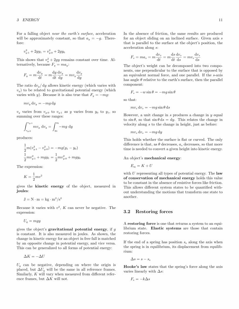
In the absence of friction, the same results are producedfor an object sliding on an inclined surface. Given axis sthat is parallel to the surface at the object’s position, theacceleration along s:
Fs = mas = mdvsdt
= mds
dt
dvsds
= mvsdvsds
The object’s weight can be decomposed into two compo-nents, one perpendicular to the surface that is opposed byan equivalent normal force, and one parallel. If the s-axishas angle θ relative to the earth’s surface, then the parallelcomponent:
Fs = −w sin θ = −mg sin θ
so that:
mvs dvs = −mg sin θ ds
However, a unit change in s produces a change in y equalto sin θ, so that sin θ ds = dy. This relates the change invelocity along s to the change in height, just as before:
mvs dvs = −mg dy
This holds whether the surface is flat or curved. The onlydifference is that, as θ decreases, as decreases, so that moretime is needed to convert a given height into kinetic energy.
An object’s mechanical energy:
Em = K + U
with U representing all types of potential energy. The lawof conservation of mechanical energy holds this valueto be constant in the absence of resistive forces like friction.This allows different system states to be quantified with-out understanding the motions that transform one state toanother.
3.2 Restoring forces
A restoring force is one that returns a system to an equi-librium state. Elastic systems are those that containrestoring forces.
If the end of a spring has position se along the axis whenthe spring is in equilibrium, its displacement from equilib-rium:
∆s = s− se
Hooke’s law states that the spring’s force along the axisvaries linearly with ∆s:
Fe = −k∆s

3 ENERGY 12
The spring constant k has units N/m, and is specific toeach spring. This is not a true ‘law’ but it models manysprings adequately if they are not over-compressed or over-stretched. In its most general form, the law is writtenwithout the negative sign, leaving the direction of the forceunstated. Including the sign shows that Fe opposes the dis-placement, and is thus a restoring force.
3.3 Elastic potential energy
If an object of mass m is connected to the end of a friction-less, massless spring, the net force along the spring’s axiswill equal −k(s − se). The force needed to accelerate theobject:
mas = mdvsdt
= mds
dt
dvsds
= mvsdvsds
As before, equating with the restoring force in this systemallows:
mvs dvs = −k(s− se) ds
This could be integrated directly, with v varying from v0
to v1 as s varies from s0 to s1. However, substitutingu = s − se changes the integration limits to the springdisplacements s0 − se and s1 − se. Because se is constant,du = d(s− se) = ds, so that:∫ v1
v0
mvs dvs =
∫ u1=(∆s)1
u0=(∆s)0
−ku du
1
2m(v2
1 − v20) = −1
2k[(∆s)2
1 − (∆s)20
]This shows that the spring’s elastic potential energy:
Ue =1
2k(∆s)2
3.4 Elastic collisions
Following a perfectly inelastic collision, objects sticktogether, after which they necessarily share a commonvelocity. During an elastic collision, objects are com-pressed, converting kinetic energy into elastic potential en-ergy. The normal forces between the objects increase untilthey are maximally compressed, then the objects expand,converting the potential energy back to kinetic energy. Thenormal forces drop to zero as this happens, and the colli-sion ends. The duration of such a collision depends on theconstruction of the objects, but one to ten milliseconds iscommon. In a perfectly elastic collision this process is
perfectly efficient, and all mechanical energy is conserved.Harder materials produce shorter and more perfectly elas-tic collisions.
Momentum is conserved during all interactions; this followsfrom Newton’s third law, which guarantees that a force pro-ducing a momentum change on one object is matched bya force producing an opposite change on some other ob-ject. As a result, in the absence of any external force, asystem’s center of mass undergoes constant, steady mo-tion, even as its components collide or otherwise interact.Though momentum is conserved, kinetic energy is lost ifthe objects are imperfectly elastic. Because a differencein kinetic energy represents a difference in velocity, whichin turn suggests a difference in momentum, this seems toimply that momentum is not conserved. However, for anytwo or more objects, there is a range of individual veloc-ities that combine to produce the same total momentum,and different points in this range yield different amounts ofkinetic energy. This is why inelastic collisions can convertkinetic energy to thermal or other types of energy withoutchanging the momentum of the system as a whole.
In a perfectly elastic collision between objects A and B,both momentum and mechanical energy will be conserved.If the motion is limited to one dimension, and if A is inmotion when the objects meet, and B at rest, the totalmomentum:
mAvA:1 +mBvB:1 = mAvA:0
If there is no restoring force, the total energy:
1
2mAv
2A:1 +
1
2mBv
2B:1 =
1
2mAv
2A:0
Solving the first equation for vA:1 and substituting into thesecond eventually produces:
vB:1
[(1 +
mB
mA
)vB:1 − 2vA:0
]= 0
This yields two solutions. The first, vB:1 = 0, describes thecase where the objects do not meet. In the second:
vB:1 =2mA
mA +mB
vA:0
Returning this to the momentum equation gives:
vA:1 =mA −mB
mA +mB
vA:0
This produces five possible outcomes for a perfectly elasticcollision:
� If mA � mB, A bounces backward at most of its orig-inal speed, and B moves forward slowly;
3 ENERGY 13
� If mA < mB, A bounces backward, and B moves for-ward;
� If mA = mB, A stops, and B moves forward at A’soriginal velocity;
� If mA > mB, A continues forward at a slower rate, andB moves ahead of it at a rate greater than A’s originalspeed;
� If mA � mB, A continues forward at nearly its origi-nal velocity, and B moves ahead of it at almost twicethat rate.
The Galilean transformation of velocity allows these resultsto be used even when both objects are in motion: simplychose a new frame with velocity V equal to one of the ve-locities in the original frame. Within the new frame, eachobject has velocity v ′ = v−V . If they have the same mass,the objects will exchange velocities just as they would if onewere at rest.
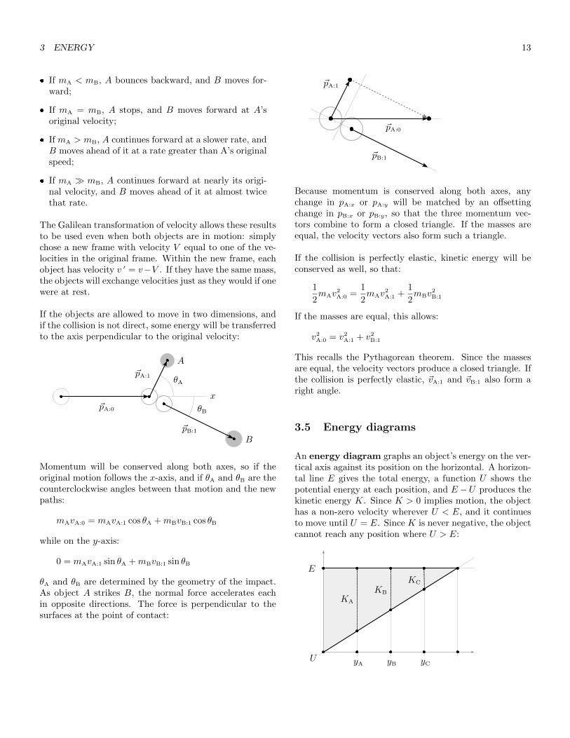
If the objects are allowed to move in two dimensions, andif the collision is not direct, some energy will be transferredto the axis perpendicular to the original velocity:
θA
θB~pA:0
~pA:1
~pB:1
A
B
x
Momentum will be conserved along both axes, so if theoriginal motion follows the x-axis, and if θA and θB are thecounterclockwise angles between that motion and the newpaths:
mAvA:0 = mAvA:1 cos θA +mBvB:1 cos θB
while on the y-axis:
0 = mAvA:1 sin θA +mBvB:1 sin θB
θA and θB are determined by the geometry of the impact.As object A strikes B, the normal force accelerates eachin opposite directions. The force is perpendicular to thesurfaces at the point of contact:
~pA:0
~pA:1
~pB:1
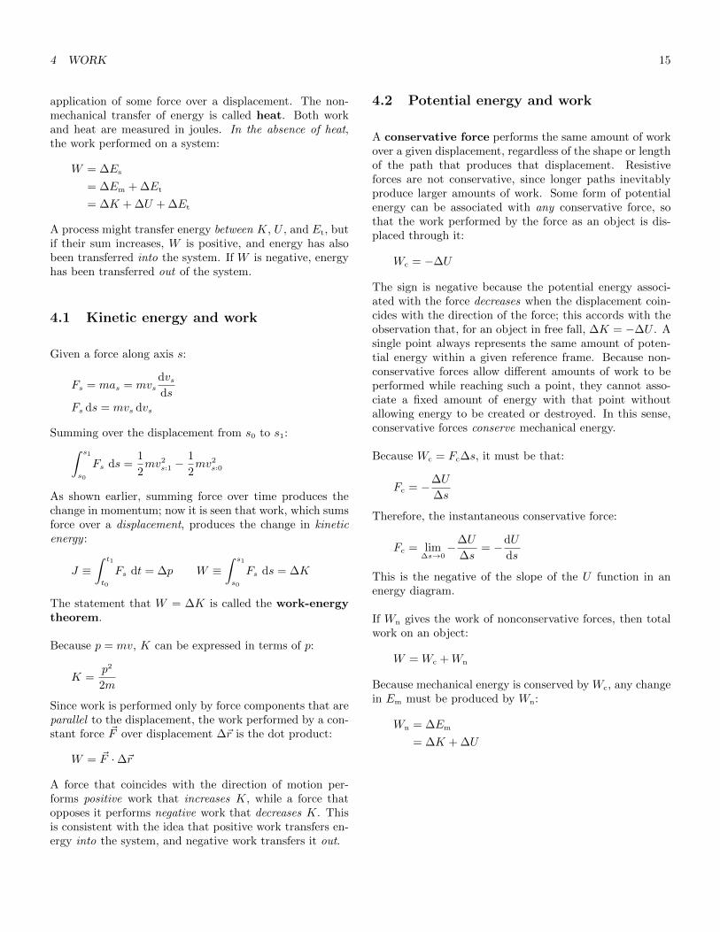
Because momentum is conserved along both axes, anychange in pA:x or pA:y will be matched by an offsettingchange in pB:x or pB:y, so that the three momentum vec-tors combine to form a closed triangle. If the masses areequal, the velocity vectors also form such a triangle.
If the collision is perfectly elastic, kinetic energy will beconserved as well, so that:
1
2mAv
2A:0 =
1
2mAv
2A:1 +
1
2mBv
2B:1
If the masses are equal, this allows:
v2A:0 = v2
A:1 + v2B:1
This recalls the Pythagorean theorem. Since the massesare equal, the velocity vectors produce a closed triangle. Ifthe collision is perfectly elastic, ~vA:1 and ~vB:1 also form aright angle.
3.5 Energy diagrams
An energy diagram graphs an object’s energy on the ver-tical axis against its position on the horizontal. A horizon-tal line E gives the total energy, a function U shows thepotential energy at each position, and E −U produces thekinetic energy K. Since K > 0 implies motion, the objecthas a non-zero velocity wherever U < E, and it continuesto move until U = E. Since K is never negative, the objectcannot reach any position where U > E:
E
yA yC
KA
KC
U yB
KB

4 WORK 14
For a bouncing object, the horizontal axis gives the verti-cal position y, and U is mgy, producing a straight line thatintersects the origin. The object has its maximum kineticenergy when y is zero; as it moves upward, U increases andK decreases until U and E meet at the object’s maximumheight. The object then falls, and U is converted to Kuntil y is zero again, where another bounce occurs. Thissequence then repeats.
For an object connected to a spring, the horizontal axisshows the object’s axial position s, and U is − 1
2k(s− se)
2,producing a parabola with its vertex where energy is zeroand where the displacement is se. K cannot be negative,so E must intersect the parabola at one or two points. If itintersects at the vertex, the system contains no energy, andno motion will result. If E is increased, the intersectionswill show the points at which the spring is most compressedand most stretched, and the system will oscillate betweenthose displacements:
E
smin smax
U
se
Ke
As will be seen, negating the slope of U gives the net con-servative force acting on the object, so if the slope is zerowhen U = E (so that K = 0) the object will stop; oth-erwise, it will turn and resume its motion in the oppositedirection:
EU
U
ES
sS sU
Fc = −dUds
0
Local minima and maxima in U are equilibrium positionswhere it is possible for the object to rest. Maxima areunstable equilibria, since even small increases in E rep-resent motion that will move the object into regions of forcethat reinforce that motion. Minima are stable equilib-ria, since small increases will move the object into regionsthat oppose the motion, leaving the object to oscillate be-tween nearby points. Geometrically, the result is deter-mined by the sign of the slope of the conservative forcefunction (−d2U/ ds2) at the equilibrium position. At un-stable equilibra, the sign is positive, so that forward motionproduces a positive force, and backwards motion producesa negative force. At stable equilibria, the sign is negative,so that the force is reversed relative to the motion. Regionswhere U is flat are known as neutral equilibria.
4 Work
An object’s thermal energy Et is the total kinetic energyof the molecules within it, along with the potential energyrepresented by stretched or compressed molecular bonds.The system energy of one or more objects:
Es ≡ Em + Et
= K + U + Et
The conversion of one energy type to another is called en-ergy transformation. The exchange of energy betweena system and its environment is called energy transfer.
The mechanical transfer of energy to or from a systemis called work; as will be seen, this is produced by the
4 WORK 15
application of some force over a displacement. The non-mechanical transfer of energy is called heat. Both workand heat are measured in joules. In the absence of heat,the work performed on a system:
W = ∆Es
= ∆Em + ∆Et
= ∆K + ∆U + ∆Et
A process might transfer energy between K, U , and Et, butif their sum increases, W is positive, and energy has alsobeen transferred into the system. If W is negative, energyhas been transferred out of the system.
4.1 Kinetic energy and work
Given a force along axis s:
Fs = mas = mvsdvsds
Fs ds = mvs dvs
Summing over the displacement from s0 to s1:∫ s1
s0
Fs ds =1
2mv2
s:1 −1
2mv2
s:0
As shown earlier, summing force over time produces thechange in momentum; now it is seen that work, which sumsforce over a displacement, produces the change in kineticenergy :
J ≡∫ t1
t0
Fs dt = ∆p W ≡∫ s1
s0
Fs ds = ∆K
The statement that W = ∆K is called the work-energytheorem.
Because p = mv, K can be expressed in terms of p:
K =p2
2m
Since work is performed only by force components that areparallel to the displacement, the work performed by a con-stant force ~F over displacement ∆~r is the dot product:
W = ~F ·∆~r
A force that coincides with the direction of motion per-forms positive work that increases K, while a force thatopposes it performs negative work that decreases K. Thisis consistent with the idea that positive work transfers en-ergy into the system, and negative work transfers it out.
4.2 Potential energy and work
A conservative force performs the same amount of workover a given displacement, regardless of the shape or lengthof the path that produces that displacement. Resistiveforces are not conservative, since longer paths inevitablyproduce larger amounts of work. Some form of potentialenergy can be associated with any conservative force, sothat the work performed by the force as an object is dis-placed through it:
Wc = −∆U
The sign is negative because the potential energy associ-ated with the force decreases when the displacement coin-cides with the direction of the force; this accords with theobservation that, for an object in free fall, ∆K = −∆U . Asingle point always represents the same amount of poten-tial energy within a given reference frame. Because non-conservative forces allow different amounts of work to beperformed while reaching such a point, they cannot asso-ciate a fixed amount of energy with that point withoutallowing energy to be created or destroyed. In this sense,conservative forces conserve mechanical energy.
Because Wc = Fc∆s, it must be that:
Fc = −∆U
∆s
Therefore, the instantaneous conservative force:
Fc = lim∆s→0
−∆U
∆s= −dU
ds
This is the negative of the slope of the U function in anenergy diagram.
If Wn gives the work of nonconservative forces, then totalwork on an object:
W = Wc +Wn
Because mechanical energy is conserved by Wc, any changein Em must be produced by Wn:
Wn = ∆Em
= ∆K + ∆U

5 NEWTON’S THEORY OF GRAVITY 16
4.3 Thermal energy and work
Resistive forces are also known as dissipative forces. Suchforces are nonconservative, and because they always opposethe direction of motion, they perform negative work thatremoves Em from the system. Since they do not contributeto U , the work done by dissipative forces:
Wd = ∆K
The kinetic energy lost this way is converted to thermalenergy. If the system is not heated or cooled from the out-side:
∆Et = −Wd
Because Wd is always negative, dissipative forces alwaysincrease Et. Since friction and drag affect both the objectin motion and the surface or fluid that resists that motion,both object and environment must be examined when cal-culating ∆Et
4.4 Conservation of energy
Nonconservative forces can be divided into dissipative andexternal forces. If We is the work performed by nonconser-vative external forces:
Wn = Wd +We
Therefore:
W = Wc +Wd +We
∆K = −∆U −∆Et +We
so that:
We = ∆K + ∆U + ∆Et
The law of conservation of energy holds that the sys-tem energy of an isolated system, where there is no thermaltransfer, and where We = 0, is constant. As a result:
∆K + ∆U + ∆Et = 0
∆Em + ∆Et = 0
∆Es = 0
To solve work problems, it is necessary to understand whichforces perform work over a given displacement, whether thework of each force is positive or negative, and which typeof energy transfer is represented by the work. In general:
K0 + U0 + Et:0 +We = K1 + U1 + Et:1
with every manifestation of work representing a transferbetween two terms on the left. An equation that relatesthe total energy at one point to that at another is calledan energy equation.
4.5 Power
Power is the rate at which energy is transferred or trans-formed:
P ≡ dW
dt
Power is measured in watts, with W = J/s.
Given constant force ~F , dW = ~F ·d~r. Dividing by dt gives:
dW
dt= ~F · d~r
dt
If the angle between ~F and ~v is θ:
P = ~F · ~v = Fv cos θ
In particular, when ~v is constant and directly opposed to aconservative force like gravity, ~F ·~v gives the rate at whichpotential energy is created. This follows from the fact thatK is not changing, and v is the rate of displacement withinthe field defining that energy.
5 Newton’s theory of gravity
Kepler’s first law states that planets traverse ellipticalorbits with their sun at one focus. His second law statesthat a line drawn between the sun and an orbiting planetcovers equal areas over equal time intervals. His third lawstates that, for a given sun, the square of each planet’s or-bital period varies linearly with the cube of half the orbit’smajor axis.
Newton’s law of gravity states that, for particles of massmA and mB, separated by distance r, the magnitude of thegravitational force affecting each of them:
Fg = GmAmB
r2
with the gravitational constant:
G ≈ 6.67× 10⁻¹¹Nm2/kg2

5 NEWTON’S THEORY OF GRAVITY 17
This can be extended to include spherical objects, or thoseshaped as spherical shells, in which case r gives the dis-tance between the centers. However, for a particle inside aspherical shell, no net gravitational force is produced.
As already seen, inertial mass defines an object’s mass rel-ative to the acceleration produced by an arbitrary force:
m =F
a
The principle of equivalence holds this value to be iden-tical to the object’s gravitational mass, defined relativeto the gravitational force produced by another object ofmass M . Following from Newton’s law:
m =r2
GMFg
Since Fg = mg, the acceleration due to gravity :
g =GM
r2
As calculated, this produces a value of 9.83m/s2, ratherthan the standard 9.81m/s2 for g at sea level, though ascale will measure values lower than 9.83m/s2 at most lat-itudes. Because the earth rotates, a centripetal force isrequired to maintain an object’s position relative to thecenter of rotation. The scale measures a normal force onthe object that partially opposes the gravitational force,and the sum of the normal and gravitational forces mustproduce the required centripetal force. Near the poles, ascale measures g at 9.83m/s2; near the equator, it measures9.78m/s2, though this value is also affected by the heightof the earth’s equatorial bulge.
5.1 Gravitational potential energy
∆U has been equated with the negative work performed bya conservative force, but this provides no absolute measureof potential energy; for that, it is necessary to define a zeropoint for U . In simple gravitation problems, U is definedto be zero where y = 0, at the planet’s surface, but this isvalid only where y is much less than the planet’s radius.
If the objects were infinitely distant, the gravitational at-traction would be zero. ∆U = −Wc, so if the objects aremoved from center distance r to this infinite distance, theincrease in potential energy:
∆Ug = −∫ ∞r
Fc dy
The gravitational force is directed toward the center of theopposing object, so Fc = −GmAmB/y
2 and:
∆Ug = −∫ ∞r
−GmAmB
y2dy
= −GmAmB
r
∣∣∣∞r
= GmAmB
r
This allows potential energy values to be defined relativeto this infinite point, where Ug reaches its maximum value.If the maximum is given a value of zero in absolute terms,the absolute potential energy at any distance r will be thedifference between the potential energy at r and that atzero:
Ug = −GmAmB
r
This value can be negative because only changes in Ug
are significant. The value can be used in energy equationsjust as Ug = mgy is, and it remains accurate at any dis-tance. Ug is properly the potential energy of the system,not that of one object or the other. If one object is muchless massive, this distinction can largely be ignored, sincethe kinetic energy of the more massive object will changeonly slightly.
In a system with more than two objects, the gravitationalpotential energy is the sum of the energies between eachpair in the whole. Given a system with three objects, A,B, and C, the total:
Ug = −G(mAmB
rAB
+mAmC
rAC
+mBmC
rBC
)Over time, gravity performs work that changes K. An ob-ject’s escape speed is the minimum starting speed suffi-cient to prevent the object from returning to some attrac-tive body. To ensure this, the object’s velocity must bezero or greater away from the body after potential energyhas been maximized; this entails that the starting kineticenergy equal or exceed the difference between the startingpotential energy and the maximum. For an object to es-cape the surface of a non-rotating body of mass M andradius R, if there are no drag effects, its speed must equalor exceed:
ve =
√2GM
R
5.2 Satellite orbits
ar equals v2/r during uniform circular motion. If a satellitewith mass m follows a circular orbit around a larger body
5 NEWTON’S THEORY OF GRAVITY 18
of mass M , at distance r from that body’s center, it mustbe the case that:
GMm
r2= mar =
mv2
r
Therefore, the satellite’s speed:
v =
√GM
r
is independent of its mass. The orbital period:
T =2πr
v
Setting T to a planet’s rotational period produces ageosynchronous orbit. Substituting the result for v pro-duces:
T 2 =4π2
GMr3
which is Kepler’s third law, fit to a circular orbit.
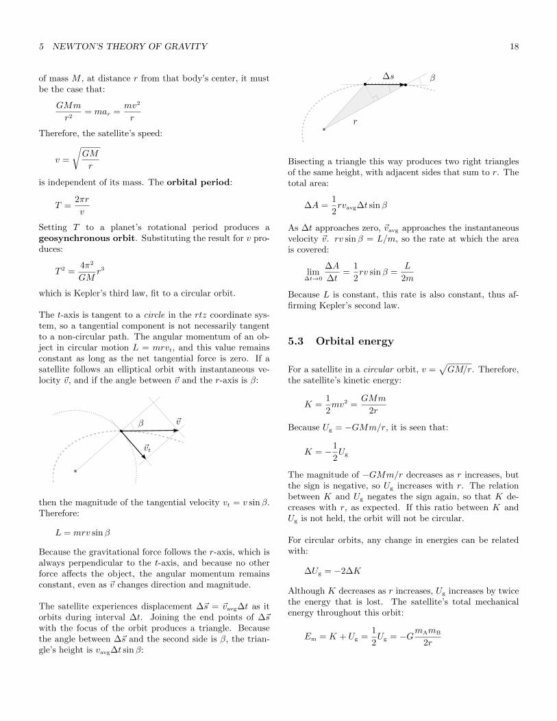
The t-axis is tangent to a circle in the rtz coordinate sys-tem, so a tangential component is not necessarily tangentto a non-circular path. The angular momentum of an ob-ject in circular motion L = mrvt, and this value remainsconstant as long as the net tangential force is zero. If asatellite follows an elliptical orbit with instantaneous ve-locity ~v, and if the angle between ~v and the r-axis is β:
β
~vt
~v
then the magnitude of the tangential velocity vt = v sinβ.Therefore:
L = mrv sinβ
Because the gravitational force follows the r-axis, which isalways perpendicular to the t-axis, and because no otherforce affects the object, the angular momentum remainsconstant, even as ~v changes direction and magnitude.
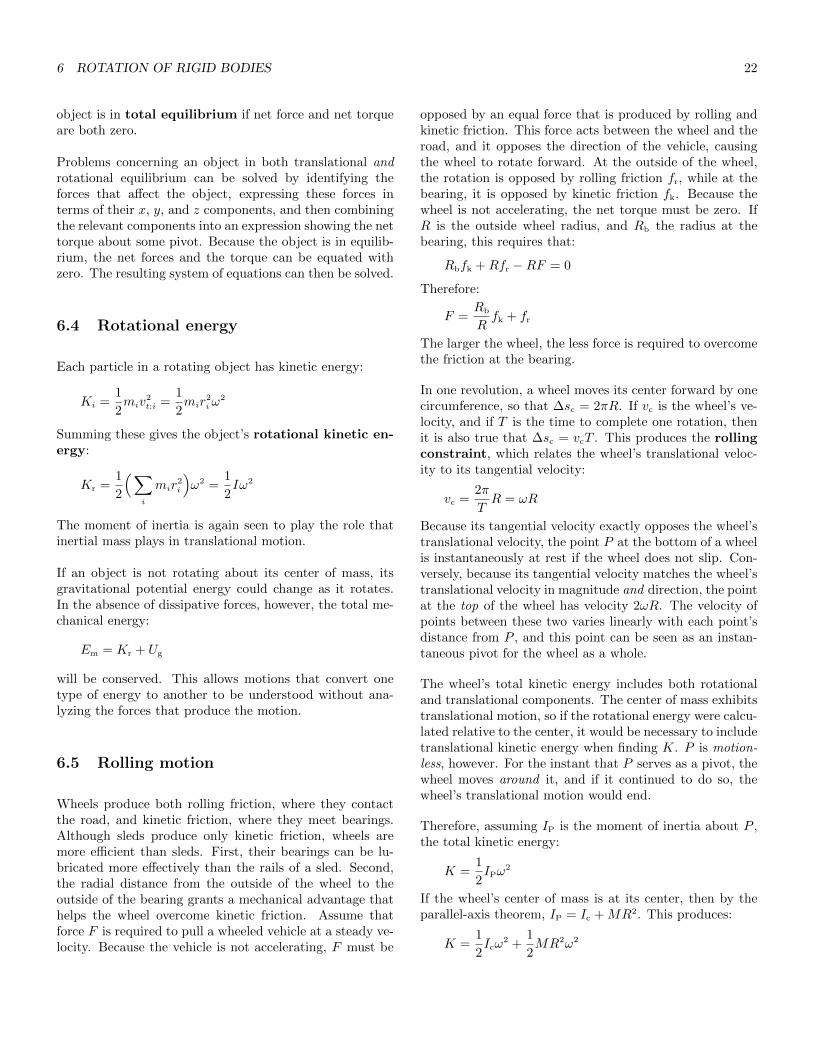
The satellite experiences displacement ∆~s = ~vavg∆t as itorbits during interval ∆t. Joining the end points of ∆~swith the focus of the orbit produces a triangle. Becausethe angle between ∆~s and the second side is β, the trian-gle’s height is vavg∆t sinβ:
β
r
∆s
Bisecting a triangle this way produces two right trianglesof the same height, with adjacent sides that sum to r. Thetotal area:
∆A =1
2rvavg∆t sinβ
As ∆t approaches zero, ~vavg approaches the instantaneousvelocity ~v. rv sinβ = L/m, so the rate at which the areais covered:
lim∆t→0
∆A
∆t=
1
2rv sinβ =
L
2m
Because L is constant, this rate is also constant, thus af-firming Kepler’s second law.
5.3 Orbital energy
For a satellite in a circular orbit, v =√GM/r. Therefore,
the satellite’s kinetic energy:
K =1
2mv2 =
GMm
2r
Because Ug = −GMm/r, it is seen that:
K = −1
2Ug
The magnitude of −GMm/r decreases as r increases, butthe sign is negative, so Ug increases with r. The relationbetween K and Ug negates the sign again, so that K de-creases with r, as expected. If this ratio between K andUg is not held, the orbit will not be circular.
For circular orbits, any change in energies can be relatedwith:
∆Ug = −2∆K
Although K decreases as r increases, Ug increases by twicethe energy that is lost. The satellite’s total mechanicalenergy throughout this orbit:
Em = K + Ug =1
2Ug = −GmAmB
2r

6 ROTATION OF RIGID BODIES 19
The same result holds for elliptical orbits if r is replacedwith the length of the semimajor axis.
The zero energy point was associated with the distanceat which the attractive force reaches zero. Because Em isnegative, this is seen to be a bound system, which is onewhere a satellite is tied to another body. For the satelliteto escape, it would need enough kinetic energy to reachthe zero point, and this would require that K ≥ −Ug. Thisequation also defines the energy change necessary to trans-fer from one orbital radius to another.
5.4 Gravitational fields
Instead of attributing gravitation to ‘action at a distance’,it is more correct to say that one object’s mass producesa spacetime distortion that changes the trajectory of otherobjects as if they were affected by a force. This distortionis called the gravitational field.
Fields are represented by vector fields that map direc-tions and magnitudes to points in space. If a gravitationalfield is created by one object, and if another object entersthat field, multiplying the mass of the second object by thefield strength at its position gives the force affecting it.
Given objects of mass M and m, the magnitude of thegravitational force F = GMm/r2, so the magnitude of thefield produced by M is g = /r2. The spherical unit vectorr points away from the origin, so placing M at the originallows the field to be expressed as:
~g = −GMr2r
The magnitude or strength of each gravitational field vectoris measured in N/kg, equivalent to m/s2.
6 Rotation of rigid bodies
Angular acceleration:
α ≡ dω
dt
Because at = dvt/dt and vt = rω, tangential acceleration,for constant r:
at = rdω
dt
Therefore, just as vt = rω:
at = rα
The kinematic equations for translational motion arestraightforwardly adapted to rotational motion:
ω1 = ω0 + α∆t
θ1 = θ0 + ω0∆t+1
2α[∆t]2
ω21 = ω2
0 + 2α∆θ
Different points on a rotating body will have different tan-gential speeds and accelerations if they vary in distancefrom the axis, but they will always have the same angularvelocity and angular acceleration.
6.1 Center of mass
When not constrained by an axle or pivot, the particles insome object will rotate about the center of mass. If theobject has mass M , and if the particles have mass mi andposition si, the center of mass along axis s will be theposition-weighted average of the particle masses:
sc =1
M
∑i
misi
This is seen from the fact that, if particle i is to rotatearound the center, it must be subject to a centripetal force:
Tr:i = miar:i = miriω2
directed toward that point. If the center’s angular positionrelative to the particle is θi:
ri
~Tr:i
θi
si sc
~Ts:i
then the s component of the particle’s centripetal force:
Ts:i = Tr:i cos θi = miriω2 cos θi
Angle θi also relates the center’s particle-relative hori-zontal position to its distance from the particle, so thatcos θi = (sc − si)/ri. As a result:∑
i
Ts:i =∑i
miriω2(sc − si
ri
)

6 ROTATION OF RIGID BODIES 20
= ω2(∑
i
misc −∑i
misi
)= ω2
(Msc −
∑i
misi
)The particle forms an action/reaction pair with the cen-ter, so the center is affected by an equal force that pulls ittoward the particle. If the center is to maintain its posi-tion, it must also be subject to a force directed away fromthe particle, so that the tension forces affecting the centeralong any axis sum to zero:∑
i
Ts:i = 0
Equating the previous result with zero and solving for sc
produces 1M
∑imisi.
More generally:
sc =1
M
∫s dm
An object’s mass will not provide ranges for the integra-tion, so dm must be replaced with an expression of ds thatrelates the change in total mass over some interval to thechange in position.
6.2 Torque
Given an object that pivots on a fixed point, the radialline is that which connects the pivot point with the pointat which some force acts. If force ~F is applied such thatthe counterclockwise angle between the radial line and ~Fis φ, then the force’s tangential component Ft = F sinφ:
r
d
~F
~Ft
φ
π − φ
φ
If the distance between the pivot and the point of applica-tion is r, the torque produced by this force:
τ ≡ rFt = rF sinφ
Torque is measured in newton-meters, Nm. Thoughnewton-meters are equivalent to joules, torque is not a mea-sure of energy, and joules are not used here.
~F is directed along the line of action. Torque increaseslinearly with r, and is greatest when the line of action isperpendicular to the radial line. When the line of actionis parallel, sinφ is zero, and the force pulls or pushes theobject without producing torque.
The distance between the pivot and the line of action iscalled the moment arm or lever arm d. The segmentdefining the moment arm is always perpendicular to theline of action. When φ is not a multiple of π/2, the mo-ment arm combines with the radial arm and the line of ac-tion to produce a right triangle with hypotenuse of lengthr, and angle π − φ at the point of application. Becausesin(π − α) = sinα:
d = r sinφ
The moment arm is a distance, not a displacement, so it isalways positive. Therefore:
|τ | = dF
When forces are applied at multiple points, the object’sresponse is determined by the net torque:
τ =∑i
τi
If an object is suspended by an axle, the net torque pro-duced by gravity is the sum of the torque values associatedwith the particles in the object. For particle i, |τi| = dimig.Because the gravitational force is perpendicular to the x-axis, and because the moment arm is perpendicular to theline of action, placing the axle at the origin allows di = |xi|.Particles to the left of the axle produce positive values ofφ and sinφ, while particles to the right produce negativevalues. Therefore:
τi = −ximig
Summing these values gives:
τg = −g∑i
mixi = −gM · 1
M
∑i
mixi
= −gMxc
where xc is the position of the center of mass relative tothe rotation axis. This allows the gravitational torque tobe calculated as if the object’s mass were entirely concen-trated at its center of mass. The object experiences notorque if the axle coincides with the center of mass, or if itis directly above or below it.
Two equal but opposite forces applied to different points onan object are known as a couple. Such forces form parallel

6 ROTATION OF RIGID BODIES 21
lines of action separated by distance l. If moment arms d0
and d1 give the perpendicular distances from the pivot toeach line, and if the pivot is somewhere between the lines,the torques will act in the same direction. Therefore:
|τ | = d0F + d1F = lF
Normally, moving a pivot changes τ , but any movement be-tween these lines lengthens one moment arm by the sameamount that the other is shortened, so all pivots producethe same torque. This is true even if the pivot is movedoutside the lines of action. When this happens, the torquefrom one force opposes the other. As a result, the differ-ence between the two moment arms is l, and the resultingnet torque equals lF , as before.
If the forces are constant in direction, the lines of actionwill change as the couple rotates. As the distance betweenthem changes, so will the torque.
6.3 Rotational dynamics
Given a particle of mass m traveling a circular path, a tan-gential force:
Ft = mat = mrα
produces tangential acceleration at. Because it is perpen-dicular to the radial line, the same force generates torque:
τ = rFt = mrat = mr2α
that in turn produces angular acceleration α. r appearstwice in mr2α, first to equate the particle’s angular dis-placement with its movement through the circle, and againto represent the mechanical advantage produced by the mo-ment arm.
All the particles in an object experience the same angu-lar acceleration α, so if τ is the net torque on an objectcontaining particles of mass mi and radius ri:
τ = α∑i
mir2i
Just as an object’s inertial mass represents its inherent re-sistance to linear acceleration, its moment of inertia:
I =∑i
mir2i
gives its resistance to angular acceleration, in units kg ·m2.By extension:
α =τ
I
Different pivots produce different moments of inertia, justas they produce different amounts of torque for a giventangential force.
More generally, for distance r from the rotation axis:
I =
∫r2 dm
As before, dm must be replaced with an expression of drthat relates changes in total mass to changes in position.
If a one-dimensional object is rotated about some pivot, themoment of inertia can be determined by placing the x-axisorigin at the pivot and integrating. However, if the originof the x′-axis is placed at the center of mass, and if thatpoint is distance d from the pivot, then the x-axis coordi-nate for a particular point is related to the x′ coordinatefor that same point by x = x′ + d. Therefore:
I =
∫x2 dm
=
∫(x′ + d)2 dm
=
∫(x′)2 dm+ 2d
∫x′ dm+ d2
∫dm
The first of these terms is the moment of inertia about thecenter of mass, if the rotation axis is parallel to the axisrunning through the pivot; if the axes are not parallel, thex-axis will be foreshortened relative to the x′-axis, and dif-ferent moments will result. The second term is 2dM timesthe center of mass relative to the x′-axis, and because thispoint was placed at the origin of that axis, this evaluatesto zero. The third term is d2 times the sum of the mass M .Therefore, if I is the moment of inertia about the pivot, ifIc is the moment of inertia about a parallel axis throughthe center of mass, and if d is the distance between theseaxes, then I can be determined using the parallel-axistheorem:
I = Ic +Md2
Similar arguments extend the theorem to objects with moredimensions. Because Md2 cannot be less than zero, I isminimized when an object is rotated about its center ofmass.
An object is in translational equilibrium if the net forceon it is zero, giving its center of mass a constant and possi-bly zero velocity. An object is in rotational equilibriumif the net torque about every point in the object is zero,giving it a constant and possibly zero angular velocity. An
6 ROTATION OF RIGID BODIES 22
object is in total equilibrium if net force and net torqueare both zero.
Problems concerning an object in both translational androtational equilibrium can be solved by identifying theforces that affect the object, expressing these forces interms of their x, y, and z components, and then combiningthe relevant components into an expression showing the nettorque about some pivot. Because the object is in equilib-rium, the net forces and the torque can be equated withzero. The resulting system of equations can then be solved.
6.4 Rotational energy
Each particle in a rotating object has kinetic energy:
Ki =1
2miv
2t:i =
1
2mir
2iω
2
Summing these gives the object’s rotational kinetic en-ergy:
Kr =1
2
(∑i
mir2i
)ω2 =
1
2Iω2
The moment of inertia is again seen to play the role thatinertial mass plays in translational motion.
If an object is not rotating about its center of mass, itsgravitational potential energy could change as it rotates.In the absence of dissipative forces, however, the total me-chanical energy:
Em = Kr + Ug
will be conserved. This allows motions that convert onetype of energy to another to be understood without ana-lyzing the forces that produce the motion.
6.5 Rolling motion
Wheels produce both rolling friction, where they contactthe road, and kinetic friction, where they meet bearings.Although sleds produce only kinetic friction, wheels aremore efficient than sleds. First, their bearings can be lu-bricated more effectively than the rails of a sled. Second,the radial distance from the outside of the wheel to theoutside of the bearing grants a mechanical advantage thathelps the wheel overcome kinetic friction. Assume thatforce F is required to pull a wheeled vehicle at a steady ve-locity. Because the vehicle is not accelerating, F must be
opposed by an equal force that is produced by rolling andkinetic friction. This force acts between the wheel and theroad, and it opposes the direction of the vehicle, causingthe wheel to rotate forward. At the outside of the wheel,the rotation is opposed by rolling friction fr, while at thebearing, it is opposed by kinetic friction fk. Because thewheel is not accelerating, the net torque must be zero. IfR is the outside wheel radius, and Rb the radius at thebearing, this requires that:
Rbfk +Rfr −RF = 0
Therefore:
F =Rb
Rfk + fr
The larger the wheel, the less force is required to overcomethe friction at the bearing.
In one revolution, a wheel moves its center forward by onecircumference, so that ∆sc = 2πR. If vc is the wheel’s ve-locity, and if T is the time to complete one rotation, thenit is also true that ∆sc = vcT . This produces the rollingconstraint, which relates the wheel’s translational veloc-ity to its tangential velocity:
vc =2π
TR = ωR
Because its tangential velocity exactly opposes the wheel’stranslational velocity, the point P at the bottom of a wheelis instantaneously at rest if the wheel does not slip. Con-versely, because its tangential velocity matches the wheel’stranslational velocity in magnitude and direction, the pointat the top of the wheel has velocity 2ωR. The velocity ofpoints between these two varies linearly with each point’sdistance from P , and this point can be seen as an instan-taneous pivot for the wheel as a whole.
The wheel’s total kinetic energy includes both rotationaland translational components. The center of mass exhibitstranslational motion, so if the rotational energy were calcu-lated relative to the center, it would be necessary to includetranslational kinetic energy when finding K. P is motion-less, however. For the instant that P serves as a pivot, thewheel moves around it, and if it continued to do so, thewheel’s translational motion would end.
Therefore, assuming IP is the moment of inertia about P ,the total kinetic energy:
K =1
2IPω
2
If the wheel’s center of mass is at its center, then by theparallel-axis theorem, IP = Ic +MR2. This produces:
K =1
2Icω
2 +1
2MR2ω2
6 ROTATION OF RIGID BODIES 23
Because vc = ωR:
K =1
2Icω
2 +1
2Mv2
c = Kr +Kc
with Kc being the translational kinetic energy of the cen-ter of mass. From this it is seen that wheels with greatermoments of inertia require greater amounts of energy toachieve a given speed. By extension, spheres, filled cylin-ders, and hollow cylinders of the same mass roll at differ-ent rates down an inclined plane, since the plane providesthe same amount of potential energy for a given mass anddisplacement. A rotating object produces a higher angularvelocity for a given amount of energy when more of its massis concentrated near its center, so a sphere rolls faster thana filled cylinder, which in turn rolls faster than a hollowcylinder.
6.6 Angular momentum
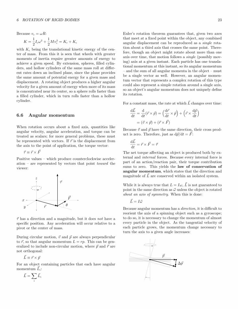
When rotation occurs about a fixed axis, quantities likeangular velocity, angular acceleration, and torque can betreated as scalars; for more general problems, these mustbe represented with vectors. If ~r is the displacement fromthe axis to the point of application, the torque vector:
~τ ≡ ~r × ~F
Positive values – which produce counterclockwise acceler-ation – are represented by vectors that point toward theviewer:
~r
~F
~τ
θ
x
y
z
~τ has a direction and a magnitude, but it does not have aspecific position. Any acceleration will occur relative to apivot or the center of mass.
During circular motion, ~v and ~p are always perpendicularto ~r, so that angular momentum L = rp. This can be gen-eralized to include non-circular motion, where ~p and ~r arenot orthogonal:
~L ≡ ~r × ~pFor an object containing particles that each have angularmomentum ~Li:
~L =∑i
~Li
Euler’s rotation theorem guarantees that, given two axesthat meet at a fixed point within the object, any combinedangular displacement can be reproduced as a single rota-tion about a third axis that crosses the same point. There-fore, though an object might rotate about more than oneaxis over time, that motion follows a single (possibly mov-ing) axis at a given instant. Each particle has one transla-tional momentum at this instant, so its angular momentum– and the sum of all angular momenta in the object – mustbe a single vector as well. However, an angular momen-tum vector that represents a complex rotation of this typecould also represent a simple rotation around a single axis,so an object’s angular momentum does not uniquely defineits rotation.
For a constant mass, the rate at which ~L changes over time:
d~L
dt=
d
dt(~r × ~p) =
(d~r
dt× ~p)
+(~r × d~p
dt
)= (~v × ~p) + (~r × ~F )
Because ~v and ~p have the same direction, their cross prod-uct is zero. Therefore, just as d~p/dt = ~F :
d~L
dt= ~r × ~F = ~τ
The net torque affecting an object is produced both by ex-ternal and internal forces. Because every internal force ispart of an action/reaction pair, their torque contributionsums to zero. This yields the law of conservation ofangular momentum, which states that the direction andmagnitude of ~L are conserved within an isolated system.
While it is always true that L = Iω, ~L is not guaranteed topoint in the same direction as ~ω unless the object is rotatedabout an axis of symmetry. When this is done:
~L = I~ω
Because angular momentum has a direction, it is difficult toreorient the axis of a spinning object such as a gyroscope;to do so, it is necessary to change the momentum of almostevery particle in the object. As the tangential velocity ofeach particle grows, the momentum change necessary toturn the axis to a given angle increases:
~p
∆~p

7 OSCILLATION 24
6.7 Precession
If a spinning top is not perpendicular to the floor, the top’saxis will circle the perpendicular axis in the same directionthat the top is spinning. This motion is called precession.
The top starts with angular momentum ~L, which alignswith the spin axis at angle φ from the perpendicular. If ~Lis made to start at the pivot, its end will trace a circle ofradius L sinφ that is centered on the perpendicular axis:
L sinφ
~L
φ
d~L
~τ
If the top has mass m, and if its center of gravity hasdisplacement ~r relative to the pivot, gravity will producetorque τ = mgr sinφ about the pivot, directed at a rightangle to ~L and tangent to the circle. By itself, this torquewould rotate the top away from the perpendicular axis, butwhen combined with ~L, it produces a lateral motion thatfollows ~τ . Because ~τ = d~L/dt, the top’s angular momen-tum changes by:
dL = mgr sinφ · dt
causing the end to traverse a small arc on the circle. Thecircle’s radius is L sinφ, while the arc length is dL, so theangle of this arc:
dθ =dL
L sin θ=mgr sinφ · dt
L sinφ
Therefore, the angular velocity of the precession:
ω =dθ
dt=mgr
L=mgr
Iω
~τ is always perpendicular to ~L and tangent to the circle,so the motion continues, with ω increasing over time asfriction diminishes L. Just as a satellite constantly ‘falls’toward the body it orbits, the top constantly rotates to-ward the floor, but it does so in a way that maintains theoverall structure of the system.
The direction of this motion is most easily understood byimagining a spinning wheel that faces the observer. If the
wheel turns counterclockwise relative to this viewpoint,particles near the left and right edges will have transla-tional momenta that point down and up. If the wheel issubjected to an upward-pointing torque that rotates theleft edge toward the observer, particles near the left andright edges will be displaced in space, but their momentawill not change in magnitude or direction. Momenta nearthe top will be changed, however; these left-pointing vec-tors will be made to point somewhat toward the observer,while right-pointing vectors near the bottom will be madeto point away. In order to conserve more of their originalmomentum, particles near the top will pitch away from theobserver, while those near the bottom will pitch toward,rotating the wheel along a third axis that is orthogonal toboth the spin axis and the torque.
The top behaves in a similar manner. As the torque rotatesit away from the perpendicular axis, translational momentaon the leading edge turn upward, while those on the trail-ing edge turn toward the floor. To maintain more of theiroriginal momentum, particles on the leading edge dip, whilethose on the trailing edge rise, causing the top as a wholeto lean in the direction of ~τ .
7 Oscillation
A periodic motion around some equilibrium position iscalled oscillatory motion. Objects that produce suchmotion are oscillators. Whereas the period T gives thetime to complete one cycle, the reciprocal of this valuegives the number of cycles completed in one unit of time.This is known as the frequency:
f =1
T
Just as an object’s angular velocity tells its rate of rotationin radians per second, an oscillator’s angular frequencygives the rate at which it cycles, also in radians per second:
ω =2π
T= 2πf
7.1 Simple harmonic motion
If an object in uniform circular motion has angular posi-tion φ relative to axis s, and if the motion has radius Aand is centered on the origin of axis s, the s-axis position:
s = A cosφ
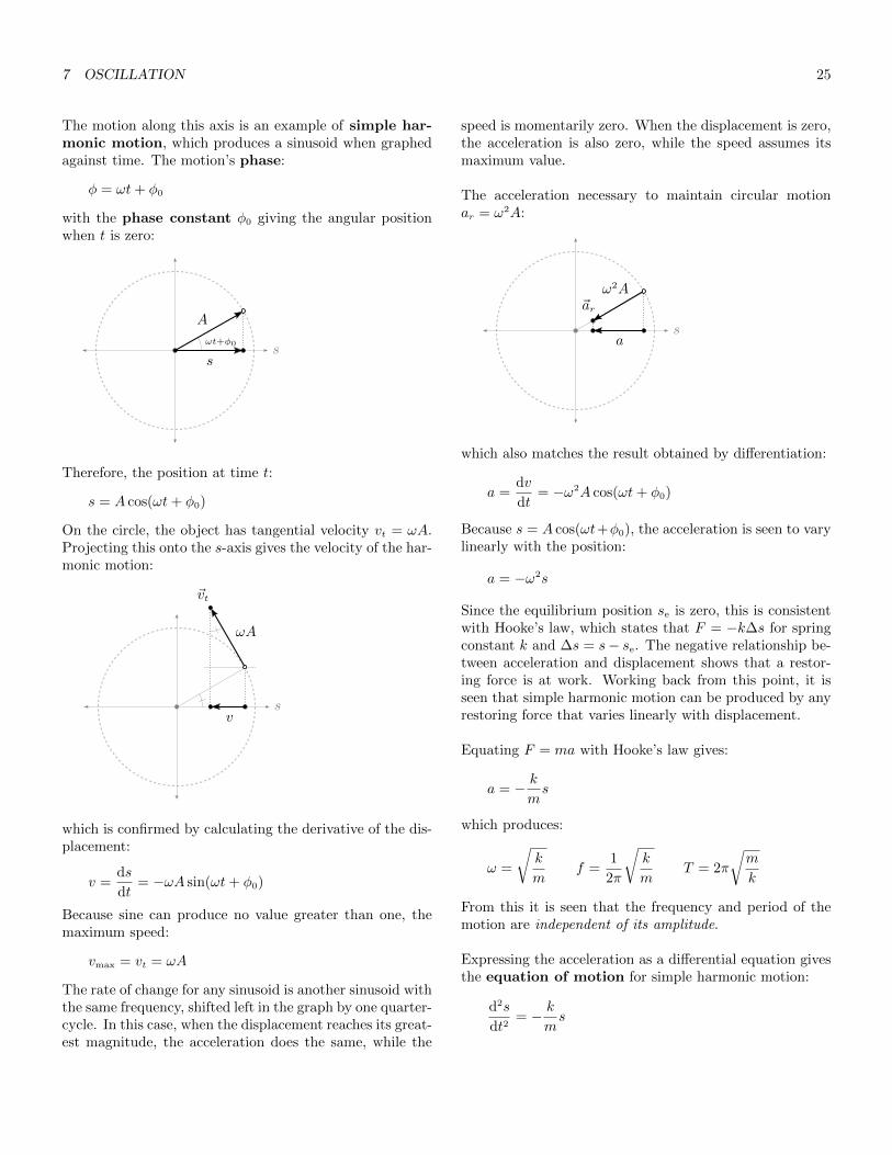
7 OSCILLATION 25
The motion along this axis is an example of simple har-monic motion, which produces a sinusoid when graphedagainst time. The motion’s phase:
φ = ωt+ φ0
with the phase constant φ0 giving the angular positionwhen t is zero:
s
A
s
ωt+φ0
Therefore, the position at time t:
s = A cos(ωt+ φ0)
On the circle, the object has tangential velocity vt = ωA.Projecting this onto the s-axis gives the velocity of the har-monic motion:
sv
ωA
~vt
which is confirmed by calculating the derivative of the dis-placement:
v =ds
dt= −ωA sin(ωt+ φ0)
Because sine can produce no value greater than one, themaximum speed:
vmax = vt = ωA
The rate of change for any sinusoid is another sinusoid withthe same frequency, shifted left in the graph by one quarter-cycle. In this case, when the displacement reaches its great-est magnitude, the acceleration does the same, while the
speed is momentarily zero. When the displacement is zero,the acceleration is also zero, while the speed assumes itsmaximum value.
The acceleration necessary to maintain circular motionar = ω2A:
s
ω2A
a
~ar
which also matches the result obtained by differentiation:
a =dv
dt= −ω2A cos(ωt+ φ0)
Because s = A cos(ωt+φ0), the acceleration is seen to varylinearly with the position:
a = −ω2s
Since the equilibrium position se is zero, this is consistentwith Hooke’s law, which states that F = −k∆s for springconstant k and ∆s = s− se. The negative relationship be-tween acceleration and displacement shows that a restor-ing force is at work. Working back from this point, it isseen that simple harmonic motion can be produced by anyrestoring force that varies linearly with displacement.
Equating F = ma with Hooke’s law gives:
a = − kms
which produces:
ω =
√k
mf =
1
2π
√k
mT = 2π
√m
k
From this it is seen that the frequency and period of themotion are independent of its amplitude.
Expressing the acceleration as a differential equation givesthe equation of motion for simple harmonic motion:
d2s
dt2= − k
ms

7 OSCILLATION 26
7.2 Energy of simple harmonic motion
As demonstrated, an object connected to an ideal springproduces simple harmonic motion after being displacedfrom the equilibrium position. If this position is placedat the origin, then the elastic potential energy:
U =1
2ks2 =
1
2kA2 cos2(ωt+ φ0)
Because v = −ωA sin(ωt+φ0) and ω =√k/m, the object’s
kinetic energy:
K =1
2mv2 =
1
2kA2 sin2(ωt+ φ0)
Therefore, its mechanical energy:
E = K + U
=1
2mv2 +
1
2ks2
=1
2kA2 sin2(ωt+ φ0) +
1
2kA2 cos2(ωt+ φ0)
m and k play identical roles in their respective terms. Theobject’s mass allows it to store kinetic energy, while thespring’s elasticity allows it to store potential energy. Allharmonic phenomena are produced by cyclical exchangesbetween two such energy forms, and similar terms will befound in every example of this behavior.
The energy diagram for this system contains a parabolic Ufunction with its vertex at the origin, where the energy isentirely kinetic. If −A or A is the initial displacement, theparabola intersects E at both these points, and the energyis entirely potential at each of them:
E
−A A
Ue
0
K
Because sin2 α+ cos2 α = 1:
E =1
2kA2
This is also seen by calculating E at displacement −A or A,where there is no kinetic energy. After equating the maxi-mum kinetic energy with the maximum potential energy:
1
2mv2
max =1
2kA2
solving for vmax gives:
vmax =
√k
mA = ωA
which matches the earlier result for maximum speed.
Because:
mv2 + ks2 = kA2
it becomes possible to solve for different variables. For in-stance, the velocity at s:
v =
√k
m
(A2 − s2
)= ω
√(A2 − s2
)
7.3 Pendulums
The bob at the end of a perfectly rigid pendulum arm willtrace a circular arc. In the absence of drag, two forces acton the bob: its weight, and the tension force exerted by thearm, which opposes the weight’s radial component. If θ isthe angle from the center line to the arm, then the anglebetween ~w and the radial line is also θ:
θ
L
θ
~w
~wt
~T
~wr
s
so that the tangential component:
wt = −mg sin θ
Because ~wt always points toward the equilibrium position,it acts as a restoring force. In this case, however, it varieswith the angular displacement, not the translational dis-placement of a spring. If the arm is massless, the tangentialacceleration of the bob:
at = −g sin θ

7 OSCILLATION 27
If s is the displacement along the arc from the equilibriumposition, and if L is the length of the arm, then s = Lθ.The small angle approximation holds that sin θ ≈ θ whenθ � 1. This allows sin θ ≈ s/L, making the angular dis-placement approximately translational:
at ≈ −g
Ls
This matches the acceleration of an oscillating spring. Ex-tending this to the other findings gives:
ω ≈√g
L
which shows the pendulum’s frequency and period to be in-dependent (for small amplitudes) of the bob’s mass. Muchlike k and m in an oscillating spring, g relates the storageof potential energy to a displacement, while L relates thestorage of kinetic energy to a speed, since a longer armproduces greater tangential velocity for a given angular ve-locity.
If the arm is not massless, the motion must be understoodnot as a translational motion through a circular path, butas a rotation of the entire pendulum. If r is the distancefrom the pivot to the center of mass, the combined tangen-tial weight produces torque:
τ = −rwt = −rmg sin θ
Using small angle approximation again:
τ ≈ −rmgθ = −rwθ
so that:
ω ≈√rw
I
for small amplitudes. In this case, the moment arm and theweight relate the storage of potential energy to a displace-ment, while the moment of inertia I relates the storage ofrotational kinetic energy to a speed.
7.4 Damped oscillation
A damped oscillation is one that decreases in amplitudeover time. Damping is caused by dissipative forces likefriction and drag. At low velocities, drag varies with speedin a roughly linear manner, so its damping force can bemodeled as:
~D = −b~v
In this context, b is known as the damping constant.This quantity produces a force when multiplied by a veloc-ity, so its unit is kg/s.
Simple harmonic motion is produced by a restoring forcelike Fr = −ks. If that force is combined with a dampingforce, then the net force:
F = −ks− bv = ma
From this it is seen that:
a+b
mv +
k
ms = 0
Expressing this as an equation of motion:
d2s
dt2+
b
m
ds
dt+k
ms = 0
This is the original equation for simple harmonic motionwith an added ds/dt term to represent damping. Becausethe damping is produced by a dissipative force, the oscilla-tor’s energy is not conserved over time.
After solving for the displacement:
s = e−bt/2mA cos(ωt+ φ0)
This is a sinusoid with an exponentially decaying enve-lope that gives the greatest possible displacement at eachpoint:
smax = e−bt/2mA
The angular frequency:
ω =
√k
m− b2
4m2=
√ω2
u −b2
4m2
with ωu representing the undamped angular frequency.Damping lowers the frequency relative to the undampedoscillator, but, as before, the frequency remains constantover time.
A damped oscillator’s time constant:
τ =m
b
gives the relationship between the mass, which resists thedamping, and the damping constant. Therefore:
smax = e−t/2τA
Because the total energy E varies with the maximum po-tential energy at each point, and because the potential en-ergy varies with the maximum displacement:
E =1
2ks2
max = e−t/τ · 1
2kA2 = e−t/τEu

8 FLUIDS 28
Eu is the energy without damping, which is also the en-ergy when t = 0. The sign of the exponent is negative, sosmaller τ values produce stronger damping. e−1 ≈ 0.37,so when t = τ , the oscillator has approximately 37% of itsoriginal energy.
Driven oscillation occurs when an oscillator is subjectedto a periodic external force. The rate at which the forceacts is called the driving frequency, and its effect is rep-resented by the oscillator’s response curve, which graphsthe amplitude of the resulting oscillation against the driv-ing frequency. In this curve, a peak will be found at theoscillator’s natural or resonant frequency f0, which isthe rate at which it would oscillate in the absence of drivingforces. Smaller damping constants produce taller, narrowerpeaks.
8 Fluids
A fluid is any substance that flows, including liquids andgases. In a liquid, molecules are connected by weak bondsthat hold the liquid together while still allowing moleculesto move around each other. Because these molecules areclose together, liquids are largely incompressible. In a gas,molecules move freely without interacting, except whenthey happen to collide. Because these molecules are looselydistributed, gases are highly compressible.
For an object with mass m and volume V , the mass den-sity:
ρ =m
V
The SI unit for mass density is kg/m3.
8.1 Pressure
Given a force ~F perpendicular to some area A, the pres-sure acting against the area:
p =F
A
Pressure is a ratio of force to area, not a force itself. TheSI unit for pressure is the pascal, Pa = N/m2.
In a liquid, pressure is produced by gravity, the force ofwhich distributes mechanically against the bottom andsides of the container. Although gravity contributesslightly to the pressure near the bottom of a container full
of gas, most of the pressure in a small container is producedby thermal effects.
Atmospheric pressure decreases with height. The stan-dard atmosphere is defined as the average pressure atsea level:
1 atm ≡ 101, 300 Pa ≈ 14.7 psi
Given a container of unmoving liquid, a column can bedefined that extends from any area A at depth d to thesurface. This column is subject to three forces: a forcep0A due to atmospheric pressure that pushes down fromthe top, another force pA that pushes up from the liquidbeneath, and the column’s weight mg. Because the columnis not moving, these forces must balance:
pA = p0A+mg
Because m = ρdA, the liquid’s hydrostatic pressure:
p = p0 + ρgd
so that a change in depth produces a proportional changein pressure:
∆p = ρg∆d
This applies to liquids because they are mostly incompress-ible, making ρ constant at all d; the relationships do nothold for gases. Because the ρgd term varies only with d,it follows that a change in pressure at any point producesan equal change in pressure at all other points, once equi-librium is achieved; this is called Pascal’s principle. Acontiguous volume of liquid will flow to the same level inall open areas of a container, regardless of its shape, andthe pressure will be the same at all points within a givenhorizontal plane.
Rather than measuring the absolute pressure p that is usedin most calculations, many gauges show the gauge pres-sure:
pg = p− 1 atm
Zero gauge pressure represents the ambient pressure. Thegauge pressure of the gas in some container can be mea-sured with a manometer, this being a U-shaped tube, oneend of which is connected to the container, and the otherend of which is open. Within the tube is a dense liquidsuch as mercury. The liquid will settle at one level in thebranch that is connected to the container, and at anotherin the open branch:

8 FLUIDS 29
p
p0
h
p0 + ρgh
p0
The pressure at the level of the connected branch is equalto the gas pressure; the pressure at the same point in theopen branch is equal to the atmospheric pressure, whichpresses down on the liquid, plus ρgh, where h is the amountby which the open level exceeds the connected level. Thepressure at these points is necessarily equal, so the gaspressure is found to be p0 + ρgh.
Atmospheric pressure can be measured with a barometer,which is constructed by sealing a tube at one end, submerg-ing and filling it within a liquid, and then raising the sealedend above the level of the liquid. If the tube is tall enough,a vacuum will form at its top. The pressure at the surfaceof the liquid matches the ambient pressure, the pressure atthe same point within the tube also matches the ambientpressure, and yet the pressure at that point is simultane-ously equal to ρgh, where h is the amount by which thelevel in the tube exceeds the open level. The ambient pres-sure is therefore found to be ρgh. At one atmosphere, amercury barometer measures 760 millimeters.
8.2 Hydraulics
A hydraulic lift is constructed by connecting a narrow ver-tical piston with area AN to a wider one with area AW:
AW
AN
~FN~FW
h
p0 + FN
ANp0 + FW
AW
+ρgh
When force ~FN presses down on the narrow piston, thepressure at that piston’s face is p0 + FN/AN. If force ~FW
presses down on the wider piston, and if h is the verti-cal distance from the narrow piston to the wider one, the
pressure at the same level within the wider piston must bep0 + FW/AW + ρgh. This gives:
FN
AN
=FW
AW
+ ρgh
so that:
FW =AW
AN
FN −AWρgh
When h is small, the force is multiplied by a value closeto the ratio of the areas. Because the pistons are orientedvertically, the effect diminishes as the weight of the liquidin the wider piston increases.
Because liquids are incompressible, displacing a volume inone piston causes a like volume to be added to the other.If the narrow piston is depressed by distance dN, the widerpiston must rise by distance:
dW =AN
AW
dN
This shows in part how energy is conserved by the system;though the wider piston is subject to and reacts with agreater force than the narrow piston, the force acts over ashorter distance. In this vertical orientation, a portion ofthe input energy is also stored in the liquid as gravitationalpotential energy.
8.3 Buoyancy
An object submerged in any fluid, whether liquid or gas, issubject to greater pressure on its bottom surface than onits top; this difference produces the buoyant force, whichpushes the object up. To calculate the force, consider thatany shape can be modeled as a collection of vertical cylin-ders. If a given cylinder has height h, then the pressure dif-ference between its bottom and top ∆p = ρgh. Because thepressure force F = pA, the amount by which the bottomforce exceeds the top is equal to ρghA, which is itself theweight of the displaced fluid. This is called Archimedes’principle. Given a completely submerged object of volumeV :
FB = ρVg
When an object’s average density matches that of the fluidsurrounding it, its weight is exactly canceled by the buoy-ant force. Such an object is said to have neutral buoy-ancy.
An object that is less dense will float, with part of its vol-ume above the fluid level so that the buoyant force exactly

8 FLUIDS 30
matches the object’s weight. Given an object with volumeVo and homogeneous density ρo, and given fluid density ρf
and displaced fluid volume Vf :
ρfVfg = ρoVog
Therefore, the ratio of the displaced fluid to the objectvolume as a whole:
Vf
Vo
=ρo
ρf
8.4 Fluid dynamics
In a laminar flow, fluid moves in discrete layers or strandsthat do not cross, without producing swirls or eddies, andthe flow rate at any point within the flow is constant overtime. At higher flow rates, the layers and strands beginto mix, and flow rates change over time, producing tur-bulent flow. A flow is irrotational if the vector fieldrepresenting the flow has zero curl at all points.
The ideal-fluid model offers a simplified description ofmotion within fluids. It assumes that the fluid is incom-pressible and nonviscous, and that the flow is laminar andirrotational. In this model, the trajectory followed by asmall volume of fluid is called a streamline; a collectionof adjacent streamlines is called a flow tube. Though aflow tube may vary in shape or cross-sectional area, it con-tains the same set of streamlines throughout its length. Aflow tube may traverse an open body of fluid, or it may flowwithin a chamber or pipe, and passing between these doesnot affect the tube unless its cross-sectional area changes.Given fluid speed v and cross-sectional area A, the volumeflow rate at a particular point:
Q = vA =∆s
∆tA =
V
∆t
The SI unit for this quantity is m3/s. The flow rate mustbe identical at every point along the tube’s length, so Vmust be constant. This is expressed in the equation ofcontinuity as:
v1A1 = v0A0
with v0 and v1 being the fluid speed at two points, andA0 and A1 the cross-sectional area at those points. Thisrequires that the fluid move faster in narrower sections ofthe tube.
Because pA = F , a section within any flow tube is subjectto two forces that press against its ends. The force on the
intake has the same direction as the flow, so it performspositive work on the section equal to:
W0 = F0(∆s)0 = p0A0(∆s)0 = p0V
The force on the outlet opposes the flow, so it performsnegative work. The total work performed on the sectionover ∆t:
We = p0V − p1V
If the intake has vertical position y0, and if the outlet hasposition y1, the change in gravitational potential energy:
∆U = mgy1 −mgy0
= ρVgy1 − ρVgy0
The change in kinetic energy:
∆K =1
2mv2
1 −1
2mv2
0
=1
2ρVv2
1 −1
2ρVv2
0
Equating the work performed on the section with thechanges in kinetic and potential energy gives the energyequation for the flow:
We = ∆K + ∆U
p0V − p1V =1
2ρVv2
1 −1
2ρVv2
0 + ρVgy1 − ρVgy0
This produces Bernoulli’s equation:
p1 +1
2ρv2
1 + ρgy1 = p0 +1
2ρv2
0 + ρgy0
which shows p + 12ρv2 + ρgy to be constant at all points
within a flow tube. When the vertical position is constant,this causes an increase in speed to produce a decrease inpressure. When the velocity is constant, an increase ingravitational potential energy also produces a decrease inpressure, which matches the results for hydrostatic pres-sure at different depths. These findings derive from theneed to conserve energy within the flow tube.
The flow speed of a gas can be measured with a Venturitube, which consists of a wide chamber followed by a nar-row chamber, with the arms of a U-shaped tube connectedto each. The tube contains a quantity of liquid:
p1p0
h

9 ELASTICITY 31
Gas flows through the chambers; because the second cham-ber is narrower than the first, the gas pressure there islower, which causes the level in that arm of the tube torise, as in a manometer. If p0 is the pressure in the firstchamber, if p1 is the pressure in the second, if ρ is the den-sity of the liquid, and if h is the amount by which the levelin the second arm exceeds that of the first:
p1 = p0 − ρgh
By the equation of continuity:
v1 =A0
A1
v0
After substituting into Bernoulli’s equation, the potentialenergy terms can be discarded, since the chambers havethe same vertical position. This produces:
p0 +1
2ρv2
0 = (p0 − ρgh) +1
2ρ(A0
A1
v0
)2
Solving for v0 gives:
v0 = A1
√2ρgh
ρ(A20 −A2
1)
Because gas is compressible, it cannot be considered anideal fluid. However, this estimate produces adequate re-sults at speeds much below the speed of sound.
Real fluids are at least somewhat viscous. As a solid objectmoves through a viscous fluid, a thin boundary layer offluid adheres to it. This layer is nearly still relative to thesurface of the object. At higher speeds, the boundary layerwill separate from the back of the object to form a turbu-lent, low-pressure region called a wake. The difference inpressure between this area and the front contributes to thedrag force on the object.
9 Elasticity
Hooke’s law provides a basic model of the force necessaryto stretch an elastic object to a given length. In its generalform:
F = k∆s
For most objects, when F is graphed against ∆s, the forceis seen to vary linearly almost to the end of the elasticregion, which ends at the yield strength, where perma-nent deformation occurs. The object will not return to itsoriginal shape after being stressed to this point, but it will
continue to resist the force until the ultimate strengthis reached, at which point it will rupture.
In Hooke’s law, the spring constant is specific to the shapeand material of the object. Because the object’s macro-scopic properties derive ultimately from molecular phenom-ena, its elasticity at the large scale can be understood bygeneralizing about molecular bonds. If a rod with cross-sectional area A is pulled with force F , the force on eachbond must be proportional to F/A. If the rod has lengths, and if it is stretched by distance ∆s, the length by whicheach bond is stretched must be proportional to ∆s/s. Aslong as the total force remains within the linear range ofthe elastic region, each bond can be modeled as a distinctspring. Though the exact force and displacement affect-ing the bonds is unknown, Hooke’s law allows them to berelated with:
F
A= Y
∆s
s
The constant Y , representing the material’s resistance todeformation, is called Young’s modulus. Rigid materialshave higher values for Y . The force per area F/A is thetensile stress affecting the object. Though tensile stressis mathematically equivalent to pressure, it acts in a spe-cific direction, so it is often expressed in N/m2 rather thanpascals. ∆s/s is the strain affecting the object, this beingthe relative amount by which it is deformed. As a whole,the equation shows that the stress necessary to produce agiven strain is equal to the strain multiplied by Young’smodulus. Strain has no units, so the modulus is expressedin N/m2, like stress. Young’s modulus is also used whenmodeling compressive stress from a single direction. Shearstress is produced by forces that are parallel to the object’scross section, with the resulting strain transforming rect-angular profiles into parallelograms. This type of stress ismodeled with the shear modulus, which has the sameunits as Young’s modulus, and is calculated in the sameway.
Because Hooke’s law gives F/∆s = k:
Y =F
A· s
∆s=
s
Ak
This allows the modulus to be determined by first measur-ing k.
Where tensile stress pulls an object from a single direc-tion, volume stress resembles pressure, in that it pushesan object from all directions. The relative amount ∆V/Vby which the object’s volume decreases is called the vol-ume strain. Much like tensile stress, volume stress varieslinearly with volume strain:
∆p = −B∆V
V
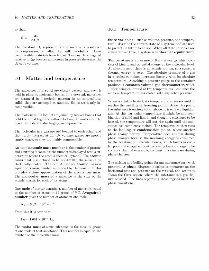
10 MATTER AND TEMPERATURE 32
so that:
B = − ∆p
∆V/V
The constant B, representing the material’s resistanceto compression, is called the bulk modulus. Less-compressible materials have higher B values. B is negatedrelative to ∆p because an increase in pressure decreases theobject’s volume.
10 Matter and temperature
The molecules in a solid are closely packed, and each isheld in place by molecular bonds. In a crystal, moleculesare arranged in a periodic pattern; in an amorphoussolid, they are arranged at random. Solids are nearly in-compressible.
The molecules in a liquid are joined by weaker bonds thathold the liquid together without locking the molecules intoplace. Liquids are also largely incompressible.
The molecules in a gas are not bonded to each other, andthey rarely interact at all. By volume, gasses are mostlyempty space, so they are highly compressible.
An atom’s atomic mass number is the number of protonsand neutrons it contains; the number is displayed with a su-perscript before the atom’s chemical symbol. The atomicmass unit u is defined to be one-twelfth the mass of anelectrically-neutral 12C atom. An atom’s atomic mass isequal to its mass number multiplied by the mass unit; thisprovides a close approximation of the atom’s true mass.The molecular mass of a molecule is the sum of theatomic masses for each of its atoms.
One mole of matter contains a number of molecules equalto the number of atoms in 12 grams of 12C. Avogadro’snumber gives the number of atoms in one mole:
NA ≈ 6.02× 10²³ mol−1
From this it is seen that:
1 u ≈ 1.661× 10⁻²⁷ kg
The molar mass of some substance is the mass in gramsof one mole of that substance. This number is equal to thenumber of the molecular mass.
10.1 Temperature
State variables – such as volume, pressure, and tempera-ture – describe the current state of a system, and are usedto predict its future behavior. When all state variables areconstant over time, a system is in thermal equilibrium.
Temperature is a measure of thermal energy, which con-sists of kinetic and potential energy at the molecular level.At absolute zero, there is no atomic motion, so a system’sthermal energy is zero. The absolute pressure of a gasin a sealed container increases linearly with its absolutetemperature. Attaching a pressure gauge to the containerproduces a constant-volume gas thermometer, which– after being calibrated at two temperatures – can infer theambient temperature associated with any other pressure.
When a solid is heated, its temperature increases until itreaches the melting or freezing point. Below this point,the substance is entirely solid; above, it is entirely liquid orgas. At this particular temperature it might be any com-bination of solid and liquid, and though it continues to beheated, the temperature will not rise again until the sub-stance has completely melted. The temperature then risesto the boiling or condensation point, where anotherphase change occurs. Temperature does not rise duringphase changes because the incoming energy is consumedby the breaking of molecular bonds, which builds molecu-lar potential energy without increasing kinetic energy. Thesystem’s thermal energy, by contrast, does increase duringphase changes.
The melting and boiling points for any substance vary withpressure. A phase diagram displays temperature on thehorizontal axis and pressure on the vertical, and within itshows the three regions where the substance is a gas, liq-uid, or solid. The lines separating these regions mark thephase transitions:

10 MATTER AND TEMPERATURE 33
T (°C)
p (atm)
0 100 374
0.006
1
218
0.01
STEAM
WATER
ICE
The gas region occupies the lower-right area, while theupper-left is split between the solid and liquid regions. Theregions meet at the triple point, which is the only com-bination of temperature and pressure that allows the threephases to coexist. At pressures below the triple point, thesubstance sublimes directly from solid to gas as the tem-perature increases. In most substances, the solid form isdenser than the liquid, so the phase boundary that risesfrom the triple point has a positive slope; this implies thatincreasing the pressure eventually causes a liquid to solid-ify. Because water ice is less dense than liquid water, thephase diagram for water shows a negative slope. The crit-ical point is found at the far end of the line separatingthe gas and liquid regions. No clear distinction betweengas and liquid exists at temperatures and pressures abovethis point; no phase transitions occur, and density variescontinuously as temperature and pressure vary.
Atoms attract each other when they are close, but theyrepel each other when they are too close. In the energydiagram for this interaction, U has an increasingly steepslope at short distances, showing the strong repulsive forcethat prevents solids and liquids from being compressed:
se
U
The function drops to a trough at the equilibrium position,and then rises to an essentially flat line where the atomsno longer interact. The ideal gas model derives from
a simplified version of this function, with a vertical lineat the contact point, and zero values everywhere beyond.This provides a good approximation of real gas behavior,as long as the density is low and the temperature is wellabove boiling.
10.2 Ideal gases
Assume that n moles of a gas in thermal equilibrium areheld by a container of volume V ; the pressure of the gasis p, and the temperature of the gas is T . Experimentally,it is seen that pV varies linearly with nT , and the slope ofthis variation is the same for gases of any substance. Thisis expressed in the ideal gas law:
pV = nRT
where the universal gas constant:
R ≈ 8.31 J/mol K
In a gas, because there are no phase changes, T varies withthe average thermal energy of each molecule, so pV varieswith the energy in the system as a whole.
n is constant in a sealed container, so pV/T = nR is con-stant as well. This gives:
p1V1
T1
=p0V0
T0
for all points in time. This is consistent with the notionthat pV and T both vary with the total thermal energy ofthe system. The particular change in each variable dependson the thermodynamic process affecting the system, whichconstrains certain variables while leaving others open.
If N is the number of molecules in the container, thenn = N/NA. This allows the ideal gas law to be restated as:
pV = NkBT
with Boltzmann’s constant giving the gas constant atthe molecular scale:
kB =R
NA
≈ 1.38× 10⁻²³ J/K
From this it is seen that the gas density, in molecules percubic meter:
N
V=
p
kBT
At standard temperature and pressure, the average dis-tance between gas molecules is approximately 5.7 nanome-ters.

11 FIRST LAW OF THERMODYNAMICS 34
10.3 Ideal gas processes
Given a constant quantity of gas in a piston or other con-tainer, the pressure-volume diagram graphs pressureagainst volume, showing how these vary as the system tran-sitions from state to state. Because pV/T is constant in asealed container, temperature is uniquely determined foreach point in the diagram. Technically, the ideal gas lawapplies only to systems in thermal equilibrium, and suchsystems do not change; for this reason, the ideal gas pro-cess described by the diagram is imagined to be a quasi-static process, which proceeds so slowly that each pointcan be considered an equilibrium. This makes ideal gasprocesses reversible, unlike real-world processes.
In an isochoric process, volume is constant over time,so that pressure varies linearly with temperature; this isrepresented in the pressure-volume diagram with a verticalline. Heating a constant-volume gas thermometer producesthis type of process.
In an isobaric process, pressure is constant over time, sothat volume varies linearly with temperature; this is rep-resented with a horizontal line. This process occurs whena gas-filled piston is heated while being compressed by aconstant force. As the temperature increases, the pressureincreases slightly, producing a net force that expands thepiston and returns it to the equilibrium pressure.
In an isothermal process, temperature is constant overtime, so that total thermal energy is constant, and p1V1 =p0V0. This is represented with a hyperbolic curve called anisotherm:
p = nR · TV
for a given T :
p
V
T0
T2
T1
This process can be produced by slowly compressing a gas-filled piston while it is cooled at a constant temperature,so that the work performed on the gas is exactly offset bythe heat lost to the environment. This balance betweenwork performed on or by the system and heat lost to orabsorbed from the environment is part of any isothermalprocess. Unlike isochoric and isobaric processes, an isother-mal process can theoretically be reversed without changingthe temperature of the heating or cooling medium.
11 First law of thermodynamics
11.1 Ideal gas processes and work
The working substance in a thermodynamic system isthe gas or other material that changes state to performwork.
A gas-filled piston with internal pressure p and piston areaA exerts force pA on the environment. If the piston ex-pands by ds, the work performed on the environment ispA ds = p dV . Conversely, the work performed on the gas:
dW = −p dV
The same result holds for a volume of any shape that ex-pands through area A with pressure p. Given a processthat begins at V0 and ends at V1:
W = −∫ V1
V0
p dV
Note that p is likely to vary with V , and if it does, it mustbe expressed as a function of V .
Work performed on the system produces a decrease involume, represented in the pressure-volume diagram as amovement from right to left. Though a low-pressure gasmight seem to pull on the environment, it is impossible fora gas to pull anything, as its molecules are not bonded.Any compression must be produced by an outside forcethat overcomes the gas pressure; as a result, compressionalways represents the performance of work on the gas, notby it.
For processes that decrease the volume, W = −∫p dV is
seen to be the area under the pressure-volume curve; forprocesses that increase the volume, W is the negative ofthat area. Because dW varies with p at each point, dif-ferent paths between the start and end points produce dif-ferent amounts of work. If a set of processes returns the
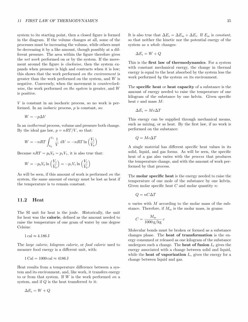
11 FIRST LAW OF THERMODYNAMICS 35
system to its starting point, then a closed figure is formedin the diagram. If the volume changes at all, some of theprocesses must be increasing the volume, while others mustbe decreasing it by a like amount, though possibly at a dif-ferent pressure. The area within the figure therefore givesthe net work performed on or by the system. If the move-ment around the figure is clockwise, then the system ex-pands when pressure is high and contracts when it is low;this shows that the work performed on the environment isgreater than the work performed on the system, and W isnegative. Conversely, when the movement is counterclock-wise, the work performed on the system is greater, and Wis positive.
V is constant in an isochoric process, so no work is per-formed. In an isobaric process, p is constant, so:
W = −p∆V
In an isothermal process, volume and pressure both change.By the ideal gas law, p = nRT/V , so that:
W = −nRT∫ V1
V0
1
VdV = −nRT ln
(V1
V0
)Because nRT = p0V0 = p1V1, it is also true that:
W = −p0V0 ln(V1
V0
)= −p1V1 ln
(V1
V0
)As will be seen, if this amount of work is performed on thesystem, the same amount of energy must be lost as heat ifthe temperature is to remain constant.
11.2 Heat
The SI unit for heat is the joule. Historically, the unitfor heat was the calorie, defined as the amount needed toraise the temperature of one gram of water by one degreeCelsius:
1 cal ≈ 4.186 J
The large calorie, kilogram calorie, or food calorie used tomeasure food energy is a different unit, with:
1 Cal = 1000 cal ≈ 4186 J
Heat results from a temperature difference between a sys-tem and its environment, and, like work, it transfers energyto or from that system. If W is the work performed on asystem, and if Q is the heat transferred to it:
∆Es = W +Q
It is also true that ∆Es = ∆Em + ∆Et. If Em is constant,so that neither the kinetic nor the potential energy of thesystem as a whole changes:
∆Et = W +Q
This is the first law of thermodynamics. For a systemwith constant mechanical energy, the change in thermalenergy is equal to the heat absorbed by the system less thework performed by the system on its environment.
The specific heat or heat capacity of a substance is theamount of energy needed to raise the temperature of onekilogram of the substance by one kelvin. Given specificheat c and mass M :
∆Et = Mc∆T
This energy can be supplied through mechanical means,such as mixing, or as heat. By the first law, if no work isperformed on the substance:
Q = Mc∆T
A single material has different specific heat values in itssolid, liquid, and gas forms. As will be seen, the specificheat of a gas also varies with the process that producesthe temperature change, and with the amount of work per-formed by that process.
The molar specific heat is the energy needed to raise thetemperature of one mole of the substance by one kelvin.Given molar specific heat C and molar quantity n:
Q = nC∆T
n varies with M according to the molar mass of the sub-stance. Therefore, if Mm is the molar mass, in grams:
C =Mm
1000 g/kgc
Molecular bonds must be broken or formed as a substancechanges phase. The heat of transformation is the en-ergy consumed or released as one kilogram of the substanceundergoes such a change. The heat of fusion Lf gives theenergy associated with a change between solid and liquid,while the heat of vaporization Lv gives the energy for achange between liquid and gas.
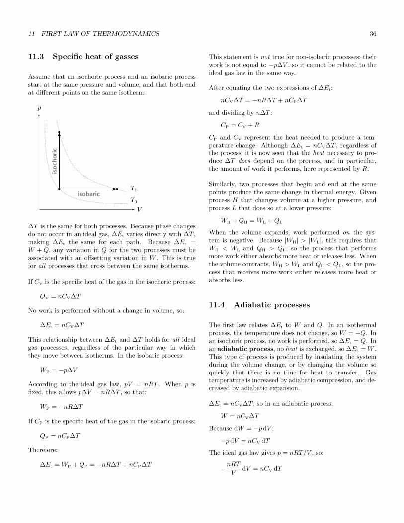
11 FIRST LAW OF THERMODYNAMICS 36
11.3 Specific heat of gasses
Assume that an isochoric process and an isobaric processstart at the same pressure and volume, and that both endat different points on the same isotherm:
p
V
T0
T1isobaric
isoch
oric
∆T is the same for both processes. Because phase changesdo not occur in an ideal gas, ∆Et varies directly with ∆T ,making ∆Et the same for each path. Because ∆Et =W + Q, any variation in Q for the two processes must beassociated with an offsetting variation in W . This is truefor all processes that cross between the same isotherms.
If CV is the specific heat of the gas in the isochoric process:
QV = nCV∆T
No work is performed without a change in volume, so:
∆Et = nCV∆T
This relationship between ∆Et and ∆T holds for all idealgas processes, regardless of the particular way in whichthey move between isotherms. In the isobaric process:
WP = −p∆V
According to the ideal gas law, pV = nRT . When p isfixed, this allows p∆V = nR∆T , so that:
WP = −nR∆T
If CP is the specific heat of the gas in the isobaric process:
QP = nCP∆T
Therefore:
∆Et = WP +QP = −nR∆T + nCP∆T
This statement is not true for non-isobaric processes; theirwork is not equal to −p∆V , so it cannot be related to theideal gas law in the same way.
After equating the two expressions of ∆Et:
nCV∆T = −nR∆T + nCP∆T
and dividing by n∆T :
CP = CV +R
CP and CV represent the heat needed to produce a tem-perature change. Although ∆Et = nCV∆T , regardless ofthe process, it is now seen that the heat necessary to pro-duce ∆T does depend on the process, and in particular,the amount of work it performs, here represented by R.
Similarly, two processes that begin and end at the samepoints produce the same change in thermal energy. Givenprocess H that changes volume at a higher pressure, andprocess L that does so at a lower pressure:
WH +QH = WL +QL
When the volume expands, work performed on the sys-tem is negative. Because |WH| > |WL|, this requires thatWH < WL and QH > QL, so the process that performsmore work either absorbs more heat or releases less. Whenthe volume contracts, WH > WL and QH < QL, so the pro-cess that receives more work either releases more heat orabsorbs less.
11.4 Adiabatic processes
The first law relates ∆Et to W and Q. In an isothermalprocess, the temperature does not change, so W = −Q. Inan isochoric process, no work is performed, so ∆Et = Q. Inan adiabatic process, no heat is exchanged, so ∆Et = W .This type of process is produced by insulating the systemduring the volume change, or by changing the volume soquickly that there is no time for heat to transfer. Gastemperature is increased by adiabatic compression, and de-creased by adiabatic expansion.
∆Et = nCV∆T , so in an adiabatic process:
W = nCV∆T
Because dW = −p dV :
−p dV = nCV dT
The ideal gas law gives p = nRT/V , so:
−nRTV
dV = nCV dT
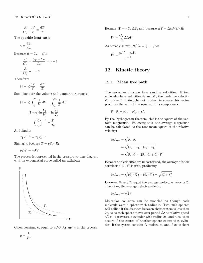
12 KINETIC THEORY 37
− R
CV
· dV
V=
dT
T
The specific heat ratio:
γ =CP
CV
Because R = CP − CV:
R
CV
=CP − CV
CV
= γ − 1
− R
CV
= 1− γ
Therefore:
(1− γ)dV
V=
dT
T
Summing over the volume and temperature ranges:
(1− γ)
∫ V1
V0
1
VdV =
∫ T1
T0
1
TdT
(1− γ) lnV1
V0
= lnT1
T0(V0
V1
)γ−1
=T1
T0
And finally:
T1Vγ−1
1 = T0Vγ−1
0
Similarly, because T = pV/nR:
p1Vγ
1 = p0Vγ
0
The process is represented in the pressure-volume diagramwith an exponential curve called an adiabat:
p
V
T0
T1
Given constant k, equal to pnVγn for any n in the process:
p =k
V γ
Because W = nCV∆T , and because ∆T = ∆(pV )/nR:
W =CV
R∆(pV )
As already shown, R/CV = γ − 1, so:
W =p1V1 − p0V0
γ − 1
12 Kinetic theory
12.1 Mean free path
The molecules in a gas have random velocities. If twomolecules have velocities ~v0 and ~v1, their relative velocity~vr = ~v0 − ~v1. Using the dot product to square this vectorproduces the sum of the squares of its components:
~vr · ~vr = v2r:x + v2
r:y + v2r:z
By the Pythagorean theorem, this is the square of the vec-tor’s magnitude. Following this, the average magnitudecan be calculated as the root-mean-square of the relativevelocity:
(vr)rms =
√~vr · ~vr
=
√(~v0 − ~v1) · (~v0 − ~v1)
=
√~v0 · ~v0 − 2~v0 · ~v1 + ~v1 · ~v1
Because the velocities are uncorrelated, the average of theircorrelation ~v0 · ~v1 is zero, producing:
(vr)rms =
√(~v0 · ~v0) + (~v1 · ~v1) =
√v2
0 + v21
However, v0 and v1 equal the average molecular velocity v.Therefore, the average relative velocity:
(vr)rms =√
2 v
Molecular collisions can be modeled as though eachmolecule were a sphere with radius r. Two such sphereswill collide if the distance between their centers is less than2r, so as each sphere moves over period ∆t at relative speed√
2 v, it traverses a cylinder with radius 2r, and a collisionoccurs if the center of another sphere enters that cylin-der. If the system contains N molecules, and if ∆t is short

12 KINETIC THEORY 38
enough that no cylinders intersect, the total volume of allcylinders:
Vc = π(2r)2 ·√
2 v∆t ·N
= 4√
2πr2v∆tN
If the system has volume V , the probability that one centerwill be within Vc during ∆t:
P =Vc
V=
4√
2πr2v∆tN
V
so that the probability density for an arbitrary point intime:
P
∆t=
4√
2πr2vN
V
The reciprocal of this value is the expected time betweencollisions. Multiplying by the average speed then gives theaverage distance between collisions, this being known asthe mean free path:
λ =∆t
Pv =
V
4√
2πr2N=
1
4√
2πr2(N/V )
Note that N/V is the molecular density. In a monatomicgas, r is approximately 0.05 nanometers.
12.2 Gas pressure
In a stationary volume of gas, the average of the molecularvelocities (vs)avg for any component s is necessarily zero. Amore useful summary can be derived from the root-mean-square speed, equal to the square root of the average ofthe velocity squares:
vrms =√
(v2)avg
Because v2 = v2x + v2
y + v2z :
(vrms)2 = (v2)avg
= (v2x)avg + (v2
y)avg + (v2z)avg
However, these components are equal on average, so that:
(vrms)2 = 3(v2
s)avg
for arbitrary component s. Conversely, the average of thesquare of any component:
(v2s)avg =
1
3(vrms)
2
As shown earlier, if one object strikes a much more mas-sive resting object, and if the collision is perfectly elastic,
the first object will rebound at nearly its original speed.Because it is so small, a single gas molecule with perpen-dicular velocity component vc can be assumed to reboundat velocity −vc after striking the side of its container. Ifthe molecule has mass m, its change in momentum:
∆p = −2mvc
This momentum change is produced by an impulse, and,by Newton’s third law, an equal and opposite impulse af-fects the container side. If Fc is the average force duringthe collision, and if ∆tc is the collision length, then thisimpulse:
J = Fc∆tc = 2mvc
Therefore, the average force during the collision:
Fc =2mvc
∆tc
If every molecule is assumed to have perpendicular speed|vc|, then the half of these that are moving toward the sidewill travel ∆s = vc∆tc during ∆tc, and the ones within∆s of the side will strike it. If the side has area A, thevolume containing these molecules is A∆s. If the systemas a whole contains N molecules in volume V , the numberthat will strike the side:
Nc =A∆s
2
(NV
)=Avc∆tc
2
(NV
)The total force from all collisions:
F = NcFc =Avc∆tc
2
(NV
)(2mvc
∆tc
)= mv2
cA(NV
)To produce a more general result, it can be assumed thatvc = (vs)rms for perpendicular component s. Because thesquare of this value is (v2
s)avg:
F = m(v2s)avgA
(NV
)=
1
3m(vrms)
2A(NV
)Dividing by A gives the pressure against the side:
p =1
3m(vrms)
2(NV
)

12 KINETIC THEORY 39
12.3 Gas temperature
For a molecule with mass m and speed v, the translationalkinetic energy:
ε =1
2mv2
Because (v2)avg = (vrms)2, the average of this energy:
εavg =1
2m(v2)avg =
1
2m(vrms)
2
From this it follows that (vrms)2 = 2εavg/m and:
p =2
3εavg
N
VpV =
2
3εavgN
By the ideal gas law, pV = NkBT , so that:
εavg =3
2kBT T =
2
3· εavg
kB
for molecules with only translational energy. Note that en-ergy varies linearly with temperature, as expected. Thissupports the assumption that molecular collisions are per-fectly elastic. If they were not, kinetic energy would de-crease with each collision, causing the temperature to dropover time.
By equating 32kBT with 1
2m(vrms)
2, it is seen that themolecular velocity in this gas:
vrms =
√3kBT
m
12.4 Thermal energy and specific heat
A system’s thermal energy includes the translational andvibrational kinetic energy of the molecules within it, alongwith the potential energy associated with stretched or com-pressed molecular bonds:
Et = Km + Um
The molecules in a monatomic gas have no bonds, and theirkinetic energy is entirely translational, so that:
Et = Km = Nεavg
for a system of N molecules. Therefore:
Et =3
2NkBT =
3
2nRT
By extension:
∆Et =3
2nR∆T
But ∆Et is also related to ∆T by the specific heat of thegas, so:
nCV∆T =3
2nR∆T
Therefore, in any monatomic gas, the specific heat duringan isochoric process:
CV =3
2R
which is confirmed by experiment.
An independent parameter that partially defines the stateof some system is called a degree of freedom. Together,the degrees of freedom define the phase space, which en-compasses all possible states for the system. A molecule’stranslational kinetic energy can be expressed as:
ε =1
2mv2
x +1
2mv2
y +1
2mv2
z = εx + εy + εz
If the molecule is not bonded to others, as in a gas, then itspotential energy is zero; if it is monatomic, its rotationalkinetic energy is zero as well. This gives just three de-grees of freedom for the storage of energy in a monatomicgas. The Equipartition theorem states that the ther-mal energy of a system in thermal equilibrium is dividedequally among its degrees of freedom. Moreover, if energyvaries quadratically with a given degree of freedom, thenthe energy associated with that degree:
εQ =1
2NkBT =
1
2nRT
Because εx, εy, and εz vary quadratically with vx, vy, andvz, it is seen that the thermal energy of a monatomic gasis equal to 3
2NkBT or 3
2nRT , as expected.
The molecules in a solid have three degrees of freedom tostore kinetic energy, along with three to store the potentialenergy of compressed or stretched bonds. Because elas-tic potential energy varies quadratically with displacement,the thermal energy of a solid :
Et = 3NkBT = 3nRT
By equating this with the specific heat expression, it ispredicted that the specific heat of a solid :
C = 3R
which is close to observed values.
13 HEAT ENGINES AND REFRIGERATORS 40
Diatomic molecules have three degrees of freedom for trans-lational kinetic energy, and two for rotational energy aboutthe axes perpendicular to the bond. Kinetic and potentialenergy along the bond’s axis would seem to require twomore degrees, but at standard temperatures, quantum ef-fects prevent energy from being stored this way. Thus, ina diatomic gas:
Et =5
2NkBT =
5
2nRT
and:
CV =5
2R
which is also close to observed values. At lower tempera-tures, the rotational degrees are lost, and at higher temper-atures, the two vibrational degrees along the axis becomeactive.
12.5 Second law of thermodynamics
Pressure and temperature are macroscopic phenomenathat summarize and abstract microscopic events. A givenmacroscopic state – such as a particular concentration ofthermal energy within a mass – can be produced by a num-ber of different microscopic configurations, and entropy isa measure of that number. Some macroscopic states are as-sociated with many more configurations than others, and asthe microscopic structure evolves in an essentially randommanner, these states – and the macroscopic phenomenathey produce – become probabilistically inevitable. Thiseffect is expressed by the second law of thermodynam-ics, which states that the entropy of an isolated systemnever decreases; instead, it increases until thermal equilib-rium is reached, and then it remains constant.
As a result, when two systems touch, molecular collisionscause thermal energy to pass from the hotter system tothe cooler one; eventually all degrees of freedom in bothsystems have the same average energy, giving both sys-tems the same temperature. Assume that systems A andB start at different temperatures. Though the tempera-tures will change, the total thermal energy must remainconstant:
EAB = EA:0 + EB:0 = EA:1 + EB:1
If the systems have the same specific heat, and if they con-tain NA and NB molecules respectively, their average ther-mal energy per molecule at equilibrium:
EA:1
NA
=EB:1
NB
=EAB
NA +NB
so that:
EA:1 =NA
NA +NB
EAB
EB:1 =NB
NA +NB
EAB
13 Heat engines and refrigerators
The gas in a piston presses outward with force ~Fg. If thepiston is not to be pushed from the cylinder, the environ-ment must counter with an opposing force ~Fe. During aquasi-static process, ~Fg = −~Fe, so if WE is the work per-formed by the gas, and if W is the work performed on it:
WE = −W
This allows the first law of thermodynamics to be restatedas:
Q = WE + ∆Et
This shows that when heat is transferred to the system, ei-ther work is performed on the environment, or the system’sthermal energy is increased.
If the gas in a piston is heated, and if the force that com-presses the piston is decreased as it expands so that pVremains constant, then, by the ideal gas law, T will alsoremain constant. Since ∆Et is zero in this case, the firstlaw requires that WE = Q, and the process is seen to con-vert heat to work with perfect efficiency. The process doesnot end where it started, however, so eventually it will beunable to produce more work.
A thermodynamic cycle combines processes in a waythat returns the system to its original state. A thermalreservoir is a system with a heat capacity so great thatits temperature and thermal energy can be considered con-stant even after another system transfers heat to or fromit. A heat engine uses a thermodynamic cycle to performuseful work. During each cycle, it extracts heat QH froma high-temperature reservoir and exhausts heat QC to alow-temperature reservoir; note that, contrary to normalpractice, QC represents energy lost by the engine, whichabsorbs Q = QH−QC in total. Because each cycle returnsthe engine to its original state, ∆Et = 0. Thus, by the firstlaw:
WE = QH −QC
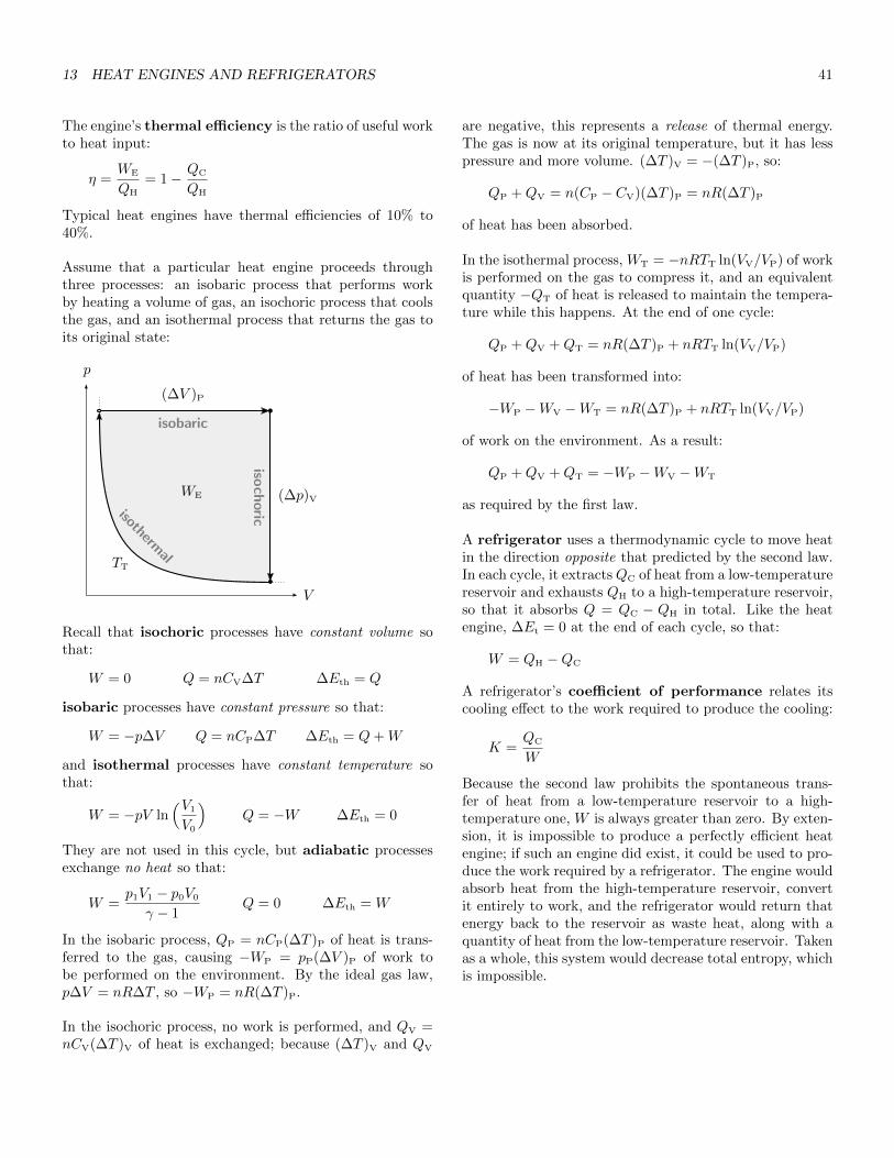
13 HEAT ENGINES AND REFRIGERATORS 41
The engine’s thermal efficiency is the ratio of useful workto heat input:
η =WE
QH
= 1− QC
QH
Typical heat engines have thermal efficiencies of 10% to40%.
Assume that a particular heat engine proceeds throughthree processes: an isobaric process that performs workby heating a volume of gas, an isochoric process that coolsthe gas, and an isothermal process that returns the gas toits original state:
p
V
(∆V )P
(∆p)V
TT
isobaric
isothermal
isoch
oric
WE
Recall that isochoric processes have constant volume sothat:
W = 0 Q = nCV∆T ∆Eth = Q
isobaric processes have constant pressure so that:
W = −p∆V Q = nCP∆T ∆Eth = Q+W
and isothermal processes have constant temperature sothat:
W = −pV ln(V1
V0
)Q = −W ∆Eth = 0
They are not used in this cycle, but adiabatic processesexchange no heat so that:
W =p1V1 − p0V0
γ − 1Q = 0 ∆Eth = W
In the isobaric process, QP = nCP(∆T )P of heat is trans-ferred to the gas, causing −WP = pP(∆V )P of work tobe performed on the environment. By the ideal gas law,p∆V = nR∆T , so −WP = nR(∆T )P.
In the isochoric process, no work is performed, and QV =nCV(∆T )V of heat is exchanged; because (∆T )V and QV
are negative, this represents a release of thermal energy.The gas is now at its original temperature, but it has lesspressure and more volume. (∆T )V = −(∆T )P, so:
QP +QV = n(CP − CV)(∆T )P = nR(∆T )P
of heat has been absorbed.
In the isothermal process, WT = −nRTT ln(VV/VP) of workis performed on the gas to compress it, and an equivalentquantity −QT of heat is released to maintain the tempera-ture while this happens. At the end of one cycle:
QP +QV +QT = nR(∆T )P + nRTT ln(VV/VP)
of heat has been transformed into:
−WP −WV −WT = nR(∆T )P + nRTT ln(VV/VP)
of work on the environment. As a result:
QP +QV +QT = −WP −WV −WT
as required by the first law.
A refrigerator uses a thermodynamic cycle to move heatin the direction opposite that predicted by the second law.In each cycle, it extractsQC of heat from a low-temperaturereservoir and exhausts QH to a high-temperature reservoir,so that it absorbs Q = QC − QH in total. Like the heatengine, ∆Et = 0 at the end of each cycle, so that:
W = QH −QC
A refrigerator’s coefficient of performance relates itscooling effect to the work required to produce the cooling:
K =QC
W
Because the second law prohibits the spontaneous trans-fer of heat from a low-temperature reservoir to a high-temperature one, W is always greater than zero. By exten-sion, it is impossible to produce a perfectly efficient heatengine; if such an engine did exist, it could be used to pro-duce the work required by a refrigerator. The engine wouldabsorb heat from the high-temperature reservoir, convertit entirely to work, and the refrigerator would return thatenergy back to the reservoir as waste heat, along with aquantity of heat from the low-temperature reservoir. Takenas a whole, this system would decrease total entropy, whichis impossible.
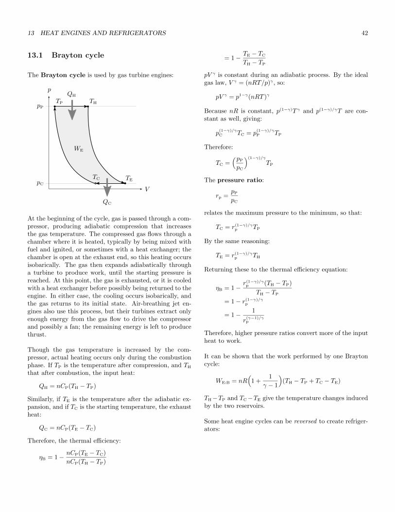
13 HEAT ENGINES AND REFRIGERATORS 42
13.1 Brayton cycle
The Brayton cycle is used by gas turbine engines:
WE
p
V
TP TH
TETC
pP
pC
QH
QC
At the beginning of the cycle, gas is passed through a com-pressor, producing adiabatic compression that increasesthe gas temperature. The compressed gas flows through achamber where it is heated, typically by being mixed withfuel and ignited, or sometimes with a heat exchanger; thechamber is open at the exhaust end, so this heating occursisobarically. The gas then expands adiabatically througha turbine to produce work, until the starting pressure isreached. At this point, the gas is exhausted, or it is cooledwith a heat exchanger before possibly being returned to theengine. In either case, the cooling occurs isobarically, andthe gas returns to its initial state. Air-breathing jet en-gines also use this process, but their turbines extract onlyenough energy from the gas flow to drive the compressorand possibly a fan; the remaining energy is left to producethrust.
Though the gas temperature is increased by the com-pressor, actual heating occurs only during the combustionphase. If TP is the temperature after compression, and TH
that after combustion, the input heat:
QH = nCP(TH − TP)
Similarly, if TE is the temperature after the adiabatic ex-pansion, and if TC is the starting temperature, the exhaustheat:
QC = nCP(TE − TC)
Therefore, the thermal efficiency:
ηB = 1− nCP(TE − TC)
nCP(TH − TP)
= 1− TE − TC
TH − TP
pV γ is constant during an adiabatic process. By the idealgas law, V γ = (nRT/p)γ , so:
pV γ = p1−γ(nRT )γ
Because nR is constant, p(1−γ)T γ and p(1−γ)/γT are con-stant as well, giving:
p(1−γ)/γC TC = p(1−γ)/γ
P TP
Therefore:
TC =(pP
pC
)(1−γ)/γ
TP
The pressure ratio:
rp =pP
pC
relates the maximum pressure to the minimum, so that:
TC = r(1−γ)/γp TP
By the same reasoning:
TE = r(1−γ)/γp TH
Returning these to the thermal efficiency equation:
ηB = 1−r(1−γ)/γ
p (TH − TP)
TH − TP
= 1− r(1−γ)/γp
= 1− 1
r(γ−1)/γp
Therefore, higher pressure ratios convert more of the inputheat to work.
It can be shown that the work performed by one Braytoncycle:
WE:B = nR(
1 +1
γ − 1
)(TH − TP + TC − TE)
TH−TP and TC−TE give the temperature changes inducedby the two reservoirs.
Some heat engine cycles can be reversed to create refriger-ators:

13 HEAT ENGINES AND REFRIGERATORS 43
p
V
W
QC
QH
pP
pC
TP TH
TETC
When the Brayton cycle is reversed, it starts, as before,with an adiabatic compression, but the direction is reversedso that the compression occurs in the high-volume portionof the cycle; this increases the temperature without heatingthe gas, making it hotter than the high-temperature reser-voir outside the refrigerator. The gas cools isobarically inthis reservoir before being expanded adiabatically to lowerits temperature below that inside the refrigerator. Finally,the gas is heated isobarically within the refrigerator; thiscools the interior and returns the gas to its initial state.
In total, W work has been performed on the gas, QC heathas been absorbed, and QH = QC + W has been released.Note that, in addition to changing the direction of theprocess, it is necessary to change the temperatures of thetwo reservoirs. In the engine, heat is transferred from thehigh-temperature reservoir to the gas, so the reservoir musthave temperature TH or greater. In the refrigerator, heat istransferred from the gas to the reservoir, so the reservoirmust have temperature TP or lower. The diagram showsthat TP < TH, so no single reservoir can meet these criteria.A similar problem affects the low-temperature reservoir.
13.2 Otto cycle
The Otto cycle is used by spark-ignition engines, com-monly known as gasoline engines:
WE
p
V
TP
TH
TE
TC
VP VC
QH
QC
At the beginning of each two-stroke cycle, a mix of fueland air is injected into the piston where it is compressedadiabatically. The fuel mixture is then ignited by a sparkplug. Because the fuel burns so quickly, there is no timefor the piston to expand, producing an isochoric pressureand temperature increase. The hot gas expands the pis-ton adiabatically to its original volume, where an exhaustvalue opens, dropping the pressure and temperature iso-chorically to their initial values. Many engines implementfour-stroke cycles that use the next compression and ex-pansion strokes to clear exhaust and take up air and fuel,but this is thermodynamically equivalent to the two-strokecycle.
It can be shown that the work performed by one Otto cycle:
WE:O =nR
1− γ(TP − TC + TE − TH)
Given compression ratio:
rv =VC
VP
the cycle’s thermal efficiency:
ηO = 1− 1
rγ−1v
Higher compression ratios increase efficiency, but they alsoproduce higher temperatures near the end of the compres-sion stroke; if the temperature increases too much, the fuelwill ignite on its own, while the piston is still compressing.Fuels with higher octane ratings can be compressed morewithout causing early ignition.
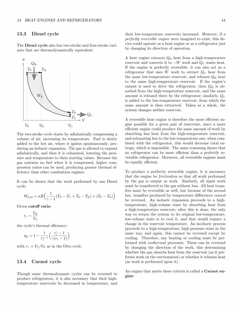
13 HEAT ENGINES AND REFRIGERATORS 44
13.3 Diesel cycle
The Diesel cycle also has two-stroke and four-stroke vari-ants that are thermodynamically equivalent:
VP
WE
p
V
TP TH
TE
TC
VH
QH
QC
VC
The two-stroke cycle starts by adiabatically compressing avolume of air, increasing its temperature. Fuel is slowlyadded to the hot air, where it ignites spontaneously, pro-ducing an isobaric expansion. The gas is allowed to expandadiabatically, and then it is exhausted, lowering the pres-sure and temperature to their starting values. Because thegas contains no fuel when it is compressed, higher com-pression ratios can be used, producing greater thermal ef-ficiency than other combustion engines.
It can be shown that the work performed by one Dieselcycle:
WE:D = nR( 1
γ − 1(TP − TC + TE − TH) + (TP − TH)
)Given cutoff ratio:
rc =VH
VP
the cycle’s thermal efficiency:
ηD = 1− 1
rγ−1v
( rγc − 1
γ(rc − 1)
)with rv = VC/VP as in the Otto cycle.
13.4 Carnot cycle
Though some thermodynamic cycles can be reversed toproduce refrigerators, it is also necessary that their high-temperature reservoirs be decreased in temperature, and
their low-temperature reservoirs increased. However, if aperfectly reversible engine were imagined to exist, this de-vice could operate as a heat engine or as a refrigerator justby changing its direction of operation.
A heat engine extracts QH heat from a high-temperaturereservoir and converts it to −W work and QC waste heat.If the engine is perfectly reversible, it can also act as arefrigerator that uses W work to extract QC heat fromthe same low-temperature reservoir, and releases QH heatto the same high-temperature reservoir. If the engine’soutput is used to drive the refrigerator, then QH is ab-sorbed from the high-temperature reservoir, and the sameamount is released there by the refrigerator; similarly, QC
is added to the low-temperature reservoir, from which thesame amount is then extracted. Taken as a whole, thesystem changes neither reservoir.
A reversible heat engine is therefore the most efficient en-gine possible for a given pair of reservoirs, since a moreefficient engine could produce the same amount of work byabsorbing less heat from the high-temperature reservoir,and exhausting less to the low-temperature one; when com-bined with the refrigerator, this would decrease total en-tropy, which is impossible. The same reasoning shows thatno refrigerator can be more efficient than a perfectly re-versible refrigerator. Moreover, all reversible engines mustbe equally efficient.
To produce a perfectly reversible engine, it is necessarythat the engine be frictionless so that all work performedby the gas is output as work. Similarly, all input workmust be transferred to the gas without loss. All heat trans-fers must be reversible as well, but because of the secondlaw, transfers produced by temperature differences cannotbe reversed. An isobaric expansion proceeds to a high-temperature, high-volume state by absorbing heat froma high-temperature reservoir; after this is done, the onlyway to return the system to its original low-temperature,low-volume state is to cool it, and that would require achange in the reservoir temperature. An isochoric processproceeds to a high-temperature, high-pressure state in thesame way, and again, this cannot be reversed except bycooling. Therefore, any heating or cooling must be per-formed with isothermal processes. These can be reversedby changing the direction of the work, this determiningwhether the gas absorbs heat from the reservoir (as it per-forms work on the environment) or whether it releases heat(as work is performed upon it).
An engine that meets these criteria is called a Carnot en-gine:

14 WAVES 45
p
V
TC
TH
WE
QC
QH
VP VC VEVH
At the start of the Carnot cycle, the gas has temper-ature TC equal to that of the low-temperature reservoir.The gas is compressed isothermally to increase its pres-sure without changing its temperature; as this happens,QC heat is passed to the reservoir, and WC = QC work isperformed on the gas. Next, it is compressed adiabaticallyto raise its pressure again, and to increase its temperatureto that of the high-temperature reservoir, TH. The gas isallowed to expand isothermally at this temperature, ab-sorbing QH from the high-temperature reservoir, and per-forming −WH = QH work on the environment. Finally, itis allowed to expand adiabatically, performing additionalwork as it drops to the starting pressure and temperature.
W = −nRT ln(V1/V0) in an isothermal process, so if VE
is the volume after the adiabatic expansion, and VC thatafter the isothermal compression:
QC = WC = −nRTC ln(VC
VE
)= nRTC ln
(VE
VC
)Similarly, if VP is the volume after the adiabatic compres-sion, and VH is that after the isothermal expansion:
QH = −WH = nRTH ln(VH
VP
)TV γ−1 is constant in an adiabatic process, so:
TCVγ−1
E = THVγ−1
H TCVγ−1
C = THVγ−1
P
and:
VE = VH
(TH
TC
)1/(γ−1)
VC = VP
(TH
TC
)1/(γ−1)
Dividing VE by VC:
VE
VC
=VH
VP
In general η = 1−QC/QH, so:
ηC = 1− QC
QH
= 1− TC ln(VE/VC)
TH ln(VH/VP)
but VE/VC = VH/VP so:
ηC = 1− TC
TH
This gives the Carnot cycle efficiency, and the maximumefficiency for any heat engine using reservoirs TC and TH.
It can be shown that the coefficient of performance for aCarnot refrigerator, and thus the maximum coefficient forany refrigerator using reservoirs TC and TH:
KC =TC
TH − TC
14 Waves
Mechanical waves traverse a material medium. A distur-bance moves some volume of material away from its equi-librium position, and a restoring force pushes it back. Forwater waves, the restoring force is gravity; for waves ona string, it is the tension force along the string’s length.Though the wave moves, and though it transfers energythrough the medium, it does not permanently displace anypart of the medium.
There are two types of mechanical wave motion. In atransverse or shear wave, particles oscillate in a direc-tion perpendicular to the wave’s travel, as in the waves ona string. In a longitudinal or compression wave, theoscillation is parallel to the travel, as when sound passesthrough a gas or liquid. Some waves, like those in water,produce both types of motion.
Oscillations produce displacement within the medium ata given position and time. In a string, this is the perpen-dicular displacement of a particle at some position alongthe length. Fluid particles do not have fixed positions, butif some volume is chosen that is large relative to the meanfree path of the particles, and small relative to the wavemotion, then displacement can be understood as the move-ment of this volume
Given a string of length L and mass m, the string’s lineardensity:
µ =m
L
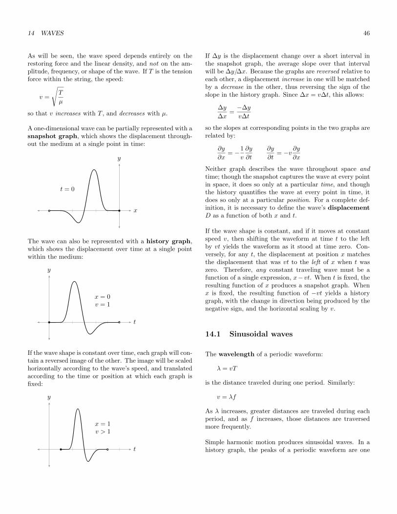
14 WAVES 46
As will be seen, the wave speed depends entirely on therestoring force and the linear density, and not on the am-plitude, frequency, or shape of the wave. If T is the tensionforce within the string, the speed:
v =
√T
µ
so that v increases with T , and decreases with µ.
A one-dimensional wave can be partially represented with asnapshot graph, which shows the displacement through-out the medium at a single point in time:
x
y
t = 0
The wave can also be represented with a history graph,which shows the displacement over time at a single pointwithin the medium:
t
y
x = 0v = 1
If the wave shape is constant over time, each graph will con-tain a reversed image of the other. The image will be scaledhorizontally according to the wave’s speed, and translatedaccording to the time or position at which each graph isfixed:
t
y
x = 1v > 1
If ∆y is the displacement change over a short interval inthe snapshot graph, the average slope over that intervalwill be ∆y/∆x. Because the graphs are reversed relative toeach other, a displacement increase in one will be matchedby a decrease in the other, thus reversing the sign of theslope in the history graph. Since ∆x = v∆t, this allows:
∆y
∆x=−∆y
v∆t
so the slopes at corresponding points in the two graphs arerelated by:
∂y
∂x= −1
v
∂y
∂t
∂y
∂t= −v ∂y
∂x
Neither graph describes the wave throughout space andtime; though the snapshot captures the wave at every pointin space, it does so only at a particular time, and thoughthe history quantifies the wave at every point in time, itdoes so only at a particular position. For a complete def-inition, it is necessary to define the wave’s displacementD as a function of both x and t.
If the wave shape is constant, and if it moves at constantspeed v, then shifting the waveform at time t to the leftby vt yields the waveform as it stood at time zero. Con-versely, for any t, the displacement at position x matchesthe displacement that was vt to the left of x when t waszero. Therefore, any constant traveling wave must be afunction of a single expression, x− vt. When t is fixed, theresulting function of x produces a snapshot graph. Whenx is fixed, the resulting function of −vt yields a historygraph, with the change in direction being produced by thenegative sign, and the horizontal scaling by v.
14.1 Sinusoidal waves
The wavelength of a periodic waveform:
λ = vT
is the distance traveled during one period. Similarly:
v = λf
As λ increases, greater distances are traveled during eachperiod, and as f increases, those distances are traversedmore frequently.
Simple harmonic motion produces sinusoidal waves. In ahistory graph, the peaks of a periodic waveform are one

14 WAVES 47
period apart, while in a snapshot graph, the peaks are onewavelength apart. To produce this type of periodicity, thesnapshot graph must be a function of x/λ. Given ampli-tude A and starting phase φ0:
D(x, t = 0) = A sin(
2πx
λ+ φ0
)x/λ = xf/v, so as f increases, the function oscillates morefrequently; as v increases, each oscillation stretches over agreater distance. Since:
D(x+ λ, t = 0) = A sin(
2πx+ λ
λ+ φ0
)= D(x, t = 0)
the function is periodic over λ, as expected.
Replacing x with x − vt releases the time constraint, pro-ducing a traveling wave:
D(x, t) = A sin(
2πx− vtλ
+ φ0
)= A sin
(2π[xλ− t
T
]+ φ0
)The position x is divided by the wavelength just as thetime t is divided by the period, so this function is periodicin space over λ, and in time over T .
Just as the angular frequency gives the number of radianstraversed per unit of time:
ω = 2πf =2π
T
the wave number gives the radians traversed per unit ofdistance:
k =2π
λ
Although k is also used to represent the spring constant,the two values are unrelated.
Because λ = 2π/k and f = ω/2π:
v = λf =2π
k· ω
2π=ω
k
and:
ω = vk
so that radians per time is equal to distance per time mul-tiplied by radians per distance.
Because 2π/λ = k and 2π/T = ω:
D(x, t) = A sin(kx− ωt+ φ0)
The phase of the wave:
φ = kx− ωt+ φ0
so the displacement function can also be written:
D(x, t) = A sinφ
The wave speed is the rate at which a given peak or troughtravels through space. Such a point has a constant dis-placement as it follows the wave, so it must also have aconstant phase as it follows the wave. If φ is constant, itstime derivative:
dφ
dt= k
dx
dt− ω = 0
From this it is again seen that the speed:
v =dx
dt=ω
k
At time t, the phase difference between points xA andxB:
∆φ = (kxB − ωt+ φ0)− (kxA − ωt+ φ0) = k∆x
= 2π∆x
λ
This follows from the fact that k is the number of radiansper unit of distance, while ∆x/λ is the number of cycleswithin ∆x.
14.2 Wave speed in strings
The waves on a string produce transverse sinusoidal mo-tion. If the displacement occurs in the y dimension, thetransverse velocity of a particle at position x:
vy =∂y
∂t= −ωA cos(kx− ωt+ φ0)
By extension, the acceleration:
ay =∂vy∂t
= −ω2A sin(kx− ωt+ φ0)
The acceleration is strongest at the peak or trough of eachcycle. At the peak:
ay:P = −ω2A = −v2sk
2A
If ∆x is a very short length of string centered around thepeak of one cycle, the net force on that length:
Fy:P ≈ may:P = µ∆x · ay:P = −µ∆x · v2sk
2A
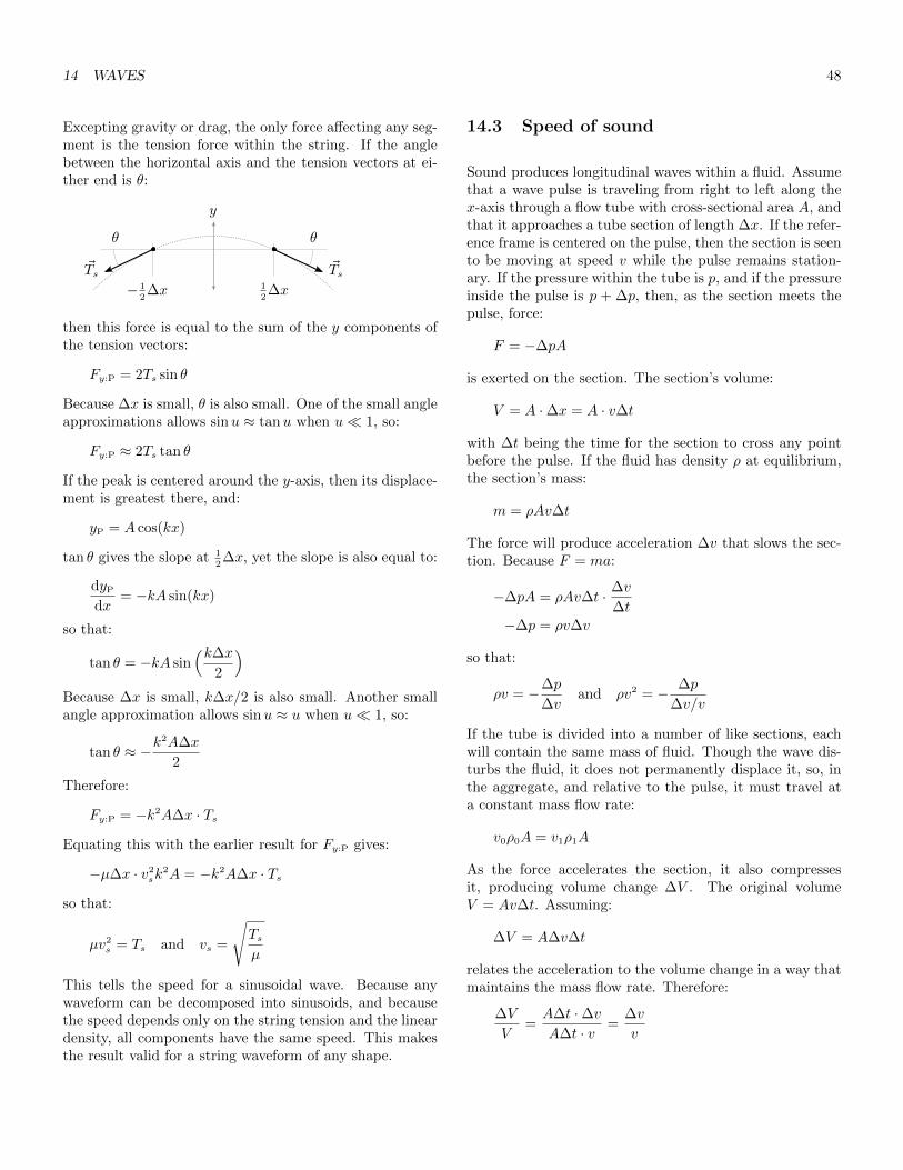
14 WAVES 48
Excepting gravity or drag, the only force affecting any seg-ment is the tension force within the string. If the anglebetween the horizontal axis and the tension vectors at ei-ther end is θ:
θθ
y
12∆x− 1
2∆x
~Ts~Ts
then this force is equal to the sum of the y components ofthe tension vectors:
Fy:P = 2Ts sin θ
Because ∆x is small, θ is also small. One of the small angleapproximations allows sinu ≈ tanu when u� 1, so:
Fy:P ≈ 2Ts tan θ
If the peak is centered around the y-axis, then its displace-ment is greatest there, and:
yP = A cos(kx)
tan θ gives the slope at 12∆x, yet the slope is also equal to:
dyP
dx= −kA sin(kx)
so that:
tan θ = −kA sin(k∆x
2
)Because ∆x is small, k∆x/2 is also small. Another smallangle approximation allows sinu ≈ u when u� 1, so:
tan θ ≈ −k2A∆x
2
Therefore:
Fy:P = −k2A∆x · Ts
Equating this with the earlier result for Fy:P gives:
−µ∆x · v2sk
2A = −k2A∆x · Ts
so that:
µv2s = Ts and vs =
√Tsµ
This tells the speed for a sinusoidal wave. Because anywaveform can be decomposed into sinusoids, and becausethe speed depends only on the string tension and the lineardensity, all components have the same speed. This makesthe result valid for a string waveform of any shape.
14.3 Speed of sound
Sound produces longitudinal waves within a fluid. Assumethat a wave pulse is traveling from right to left along thex-axis through a flow tube with cross-sectional area A, andthat it approaches a tube section of length ∆x. If the refer-ence frame is centered on the pulse, then the section is seento be moving at speed v while the pulse remains station-ary. If the pressure within the tube is p, and if the pressureinside the pulse is p + ∆p, then, as the section meets thepulse, force:
F = −∆pA
is exerted on the section. The section’s volume:
V = A ·∆x = A · v∆t
with ∆t being the time for the section to cross any pointbefore the pulse. If the fluid has density ρ at equilibrium,the section’s mass:
m = ρAv∆t
The force will produce acceleration ∆v that slows the sec-tion. Because F = ma:
−∆pA = ρAv∆t · ∆v
∆t−∆p = ρv∆v
so that:
ρv = −∆p
∆vand ρv2 = − ∆p
∆v/v
If the tube is divided into a number of like sections, eachwill contain the same mass of fluid. Though the wave dis-turbs the fluid, it does not permanently displace it, so, inthe aggregate, and relative to the pulse, it must travel ata constant mass flow rate:
v0ρ0A = v1ρ1A
As the force accelerates the section, it also compressesit, producing volume change ∆V . The original volumeV = Av∆t. Assuming:
∆V = A∆v∆t
relates the acceleration to the volume change in a way thatmaintains the mass flow rate. Therefore:
∆V
V=A∆t ·∆vA∆t · v
=∆v
v
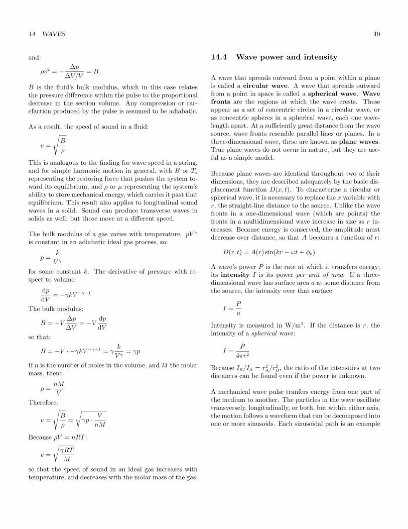
14 WAVES 49
and:
ρv2 = − ∆p
∆V/V= B
B is the fluid’s bulk modulus, which in this case relatesthe pressure difference within the pulse to the proportionaldecrease in the section volume. Any compression or rar-efaction produced by the pulse is assumed to be adiabatic.
As a result, the speed of sound in a fluid:
v =
√B
ρ
This is analogous to the finding for wave speed in a string,and for simple harmonic motion in general, with B or Tsrepresenting the restoring force that pushes the system to-ward its equilibrium, and ρ or µ representing the system’sability to store mechanical energy, which carries it past thatequilibrium. This result also applies to longitudinal soundwaves in a solid. Sound can produce transverse waves insolids as well, but those move at a different speed.
The bulk modulus of a gas varies with temperature. pV γ
is constant in an adiabatic ideal gas process, so:
p =k
V γ
for some constant k. The derivative of pressure with re-spect to volume:
dp
dV= −γkV −γ−1
The bulk modulus:
B = −V ∆p
∆V= −V dp
dV
so that:
B = −V · −γkV −γ−1 = γk
V γ= γp
If n is the number of moles in the volume, and M the molarmass, then:
ρ =nM
V
Therefore:
v =
√B
ρ=
√γp · V
nM
Because pV = nRT :
v =
√γRT
M
so that the speed of sound in an ideal gas increases withtemperature, and decreases with the molar mass of the gas.
14.4 Wave power and intensity
A wave that spreads outward from a point within a planeis called a circular wave. A wave that spreads outwardfrom a point in space is called a spherical wave. Wavefronts are the regions at which the wave crests. Theseappear as a set of concentric circles in a circular wave, oras concentric spheres in a spherical wave, each one wave-length apart. At a sufficiently great distance from the wavesource, wave fronts resemble parallel lines or planes. In athree-dimensional wave, these are known as plane waves.True plane waves do not occur in nature, but they are use-ful as a simple model.
Because plane waves are identical throughout two of theirdimensions, they are described adequately by the basic dis-placement function D(x, t). To characterize a circular orspherical wave, it is necessary to replace the x variable withr, the straight-line distance to the source. Unlike the wavefronts in a one-dimensional wave (which are points) thefronts in a multidimensional wave increase in size as r in-creases. Because energy is conserved, the amplitude mustdecrease over distance, so that A becomes a function of r:
D(r, t) = A(r) sin(kr − ωt+ φ0)
A wave’s power P is the rate at which it transfers energy;its intensity I is its power per unit of area. If a three-dimensional wave has surface area a at some distance fromthe source, the intensity over that surface:
I =P
a
Intensity is measured in W/m2. If the distance is r, theintensity of a spherical wave:
I =P
4πr2
Because IB/IA = r2A/r
2B, the ratio of the intensities at two
distances can be found even if the power is unknown.
A mechanical wave pulse tranfers energy from one part ofthe medium to another. The particles in the wave oscillatetransversely, longitudinally, or both, but within either axis,the motion follows a waveform that can be decomposed intoone or more sinusoids. Each sinusoidal path is an example

14 WAVES 50
of simple harmonic motion. As already demonstrated, themechanical energy of a particle moving this way E = 1
2kA2,
with k being the spring constant. The wave’s power is ameasure of the rate at which this energy is transferred, so,in any wave, power and intensity vary with the square ofthe amplitude.
More specifically, in a string carrying a transverse sinu-soidal wave, the transverse velocity of any short segment:
vy =∂y
∂t= −ωA cos(kx− ωt+ φ0)
This velocity is momentarily zero at each peak or trough,and it is greatest where the string crosses the x-axis. If thesegment spans length dx when projected onto the x-axis,it can be seen to approximate the unstretched, equilibriumlength at every peak or trough, while being stretched to itsgreatest extent where it crosses the axis:
dx
dx
x
This shows that the elastic potential energy is also zero atpeaks and troughs, and that it reaches its maximum valuenear the axis.
The total mass of the segment varies with its length, sothat dm = µdx for linear density µ. Therefore, the kineticenergy in the segment:
dK =1
2dm · v2
y
=1
2µdx · ω2A2 cos2(kx− ωt+ φ0)
Dividing by dt gives the rate at which kinetic energy entersand leaves the segment. Because dx/dt is the wave speedv:
dK
dt=
1
2µvω2A2 cos2(kx− ωt+ φ0)
Over a whole number of cycles, the average of the squareof cosine is one-half. Therefore:(dK
dt
)=
1
4µvω2A2
The potential energy that passes through the segment overa whole number of cycles must equal the kinetic energy, so
that the average power :
P = 2(dK
dt
)=
1
2µvω2A2
Note that the instantaneous power varies with the phaseof the wave.
As will be seen, the string’s impedance Z =√µT . Because
v =√T/µ, µv = Z, allowing the power to be expressed in
terms of impedance:
P =1
2Zω2A2
14.5 Impedance
When a traveling wave encounters a boundary in themedium, it may be reflected, or part of the wave’s energymay be passed through the boundary, leaving the rest to bereflected. Depending on the type of the wave, the reflectionmay also be inverted.
If a string wave meets a perfectly rigid boundary, it will bereflected. The fixed end of the string does not move, so anyforce exerted by the string must be opposed by an equaland opposite force. If the wave causes the string to pull up,this force will pull down on the string, and the reflectionwill be inverted. As will be seen, reflections are producedby changes in impedance, which describes a medium’s re-sistance to harmonic motion; in this case, the wave travel-ing the low-impedance string encounters an infinitely highimpedance at the rigid boundary, and is completely re-flected. The wave will also be reflected if the region pastthe boundary has a lower impedance. This can be under-stood by imagining that the string connects to a massless,frictionless ring that follows a pole in the transverse direc-tion. Beyond the ring is a massless string. The ring travelsfreely, so nothing resists the transverse motion; however,as the string pulls in the longitudinal direction, an equaland opposite force pulls back, reflecting the wave from thezero-impedance region without inverting it.
Sound is also reflected by impedance changes. A flute canbe open at one or both ends. When the sound inside a flutestrikes a closed end, the high-pressure region at each peakpresses against the rigid boundary, producing an equal andopposite force that reflects the wave. Therefore, althoughthe material at the closed end has a higher impedance,the wave is not inverted. Sound is also reflected at theopen end, where the impedance decreases. Impedance ispartly determined by the medium’s bulk modulus, andalthough the air inside a flute has the same modulus as
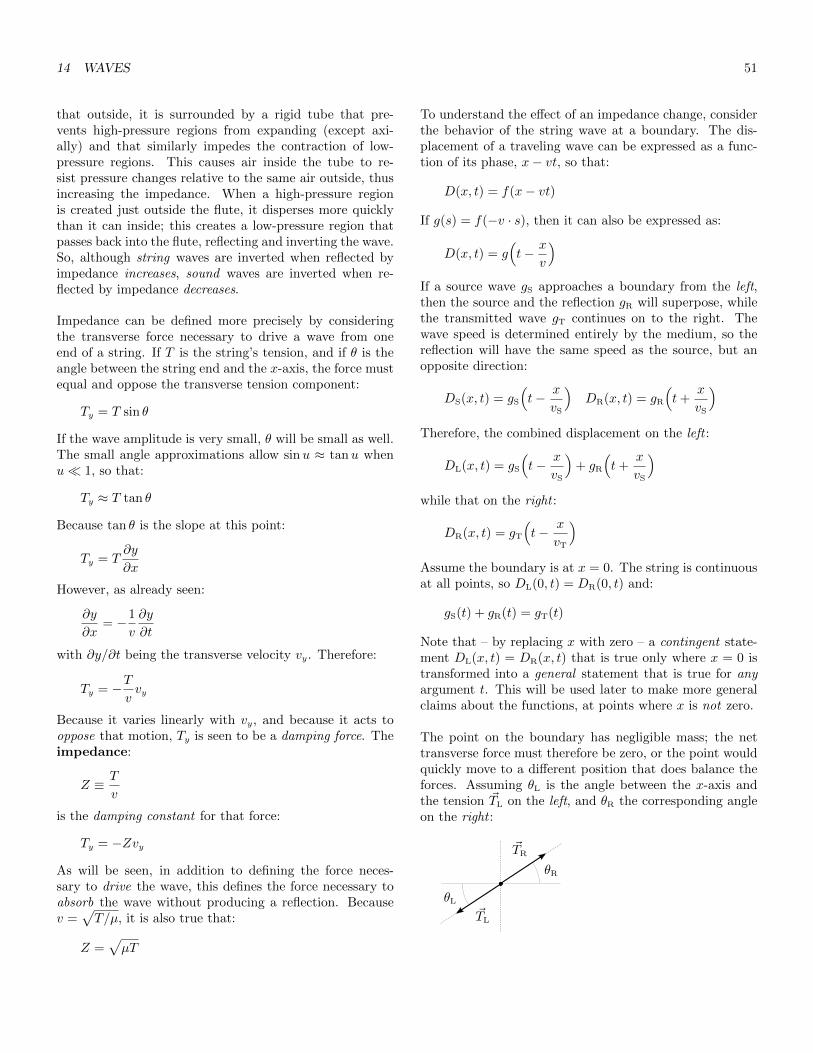
14 WAVES 51
that outside, it is surrounded by a rigid tube that pre-vents high-pressure regions from expanding (except axi-ally) and that similarly impedes the contraction of low-pressure regions. This causes air inside the tube to re-sist pressure changes relative to the same air outside, thusincreasing the impedance. When a high-pressure regionis created just outside the flute, it disperses more quicklythan it can inside; this creates a low-pressure region thatpasses back into the flute, reflecting and inverting the wave.So, although string waves are inverted when reflected byimpedance increases, sound waves are inverted when re-flected by impedance decreases.
Impedance can be defined more precisely by consideringthe transverse force necessary to drive a wave from oneend of a string. If T is the string’s tension, and if θ is theangle between the string end and the x-axis, the force mustequal and oppose the transverse tension component:
Ty = T sin θ
If the wave amplitude is very small, θ will be small as well.The small angle approximations allow sinu ≈ tanu whenu� 1, so that:
Ty ≈ T tan θ
Because tan θ is the slope at this point:
Ty = T∂y
∂x
However, as already seen:
∂y
∂x= −1
v
∂y
∂t
with ∂y/∂t being the transverse velocity vy. Therefore:
Ty = −Tvvy
Because it varies linearly with vy, and because it acts tooppose that motion, Ty is seen to be a damping force. Theimpedance:
Z ≡ T
v
is the damping constant for that force:
Ty = −Zvy
As will be seen, in addition to defining the force neces-sary to drive the wave, this defines the force necessary toabsorb the wave without producing a reflection. Becausev =
√T/µ, it is also true that:
Z =õT
To understand the effect of an impedance change, considerthe behavior of the string wave at a boundary. The dis-placement of a traveling wave can be expressed as a func-tion of its phase, x− vt, so that:
D(x, t) = f(x− vt)
If g(s) = f(−v · s), then it can also be expressed as:
D(x, t) = g(t− x
v
)If a source wave gS approaches a boundary from the left,then the source and the reflection gR will superpose, whilethe transmitted wave gT continues on to the right. Thewave speed is determined entirely by the medium, so thereflection will have the same speed as the source, but anopposite direction:
DS(x, t) = gS
(t− x
vS
)DR(x, t) = gR
(t+
x
vS
)Therefore, the combined displacement on the left :
DL(x, t) = gS
(t− x
vS
)+ gR
(t+
x
vS
)while that on the right :
DR(x, t) = gT
(t− x
vT
)Assume the boundary is at x = 0. The string is continuousat all points, so DL(0, t) = DR(0, t) and:
gS(t) + gR(t) = gT(t)
Note that – by replacing x with zero – a contingent state-ment DL(x, t) = DR(x, t) that is true only where x = 0 istransformed into a general statement that is true for anyargument t. This will be used later to make more generalclaims about the functions, at points where x is not zero.
The point on the boundary has negligible mass; the nettransverse force must therefore be zero, or the point wouldquickly move to a different position that does balance theforces. Assuming θL is the angle between the x-axis andthe tension ~TL on the left, and θR the corresponding angleon the right :
~TL
~TR
θR
θL

14 WAVES 52
the transverse tension components must be equal:
TL sin θL = TR sin θR
If the wave amplitude is again assumed to be very small,the transverse tension can be related to each slope, so that:
TL
∂DL(x, t)
∂x
∣∣∣∣x=0
= TR
∂DR(x, t)
∂x
∣∣∣∣x=0
Differentiating and replacing x with zero again:
−TL
vS
g′S(t) +TL
vS
g′R(t) = −TR
vT
g′T(t)
−ZL · g′S(t) + ZL · g′R(t) = −ZR · g′T(t)
After negating both sides, and after assuming that the dis-placements (and therefore the integration constants) arezero when t = 0, integration produces:
ZL · gS(t)− ZL · gR(t) = ZR · gT(t)
Combining this with the earlier result leads to:
gR(t) = kR · gS(t) gT(t) = kT · gS(t)
with the reflection and transmission coefficients:
kR =ZL − ZR
ZL + ZR
kT =2ZL
ZL + ZR
determining the amplitudes of the reflected and transmit-ted waves in this string. Note that 1 + kR = kT.
Recall that after a perfectly elastic collision, the speed ofobjects A and B:
vA:1 =mA −mB
mA +mB
vA:0 vB:1 =2mA
mA +mB
vA:0
The reflection and transmission coefficients take the sameform, and in both cases, the relations conserve energy. Thekinetic energy of an object, K = 1
2mv2, while the average
power of a wave:
P =1
2Zω2A2
In the wave, impedance takes the place of mass, while am-plitude takes that of velocity. The range of outcomes isalso equivalent to those of an elastic collision:
� If ZL � ZR, the reflection retains most of the sourcewave’s amplitude, while the transmitted wave is verysmall;
� If ZL < ZR, the reflected and transmitted waves areboth smaller than the source;
� If ZL = ZR, there is no reflection, and the transmittedwave is identical to the source;
� If ZL > ZR, the reflection is smaller than the source,while the transmitted wave is larger ;
� If ZL � ZR, the reflection is almost as large as thesource, while the transmitted wave has nearly twicethe amplitude.
Note that when ZL < ZR, kR is negative, producing aninverted reflection.
Because gR(t) = kR ·gS(t) and gT(t) = kT ·gS(t) are generalclaims about the gS, gR, and gT functions, t can be replacedby any argument, including t + x/vS. This works becausethe functions do nothing more than map the wave’s phase(here represented by t) to its displacement. t + x/vS re-lates the change in phase to the change in position, and aslong as it does that correctly, the phase and displacementrelationships between gS, gR, and gT continue to hold. Asa result:
gR
(t+
x
vS
)= kR · gS
(t+
x
vS
)Recalling that DR(x, t) = gR(t + x/vS) and DS(x, t) =gS(t− x/vS):
DR(x, t) = kR ·DS(−x, t)
When the boundary is placed on the y-axis, the reflection’sdisplacement at point −x is some fraction of the displace-ment the source would have if it reached point x.
A similar operation applies to the gT equation. Replacingt with t− x/vT produces:
gT
(t− x
vt
)= kT · gS
(t− x
vt
)However, this expression of gS does not match DS(x, t) =gS(t− x/vS), which uses vS. Therefore:
gT
(t− x
vt
)= kT · gS
(t− (vS/vT)x
vS
)so that:
DT(x, t) = kT ·DS
( vS
vT
x, t)
The vS/vT term shows the speed of the transmitted waveto be vT/vS times that of the source, since displacementsthat would occur at vS/vT · x instead occur at x. This isto be expected, since vT/vS · vS = vT.

14 WAVES 53
14.6 Light
Light travels at different speeds in different materials. Ifc is the speed of light in a vacuum, and if v is its speedwithin some material, then the index of refraction orrefractive index for that material:
n =c
v
This is the reciprocal of the relative speed of light withinthe material. As will be seen, the refractive index also af-fects the amount by which light bends as it passes fromone medium to another. The refractive index of a vacuumis one, and that of air is very close to one. Liquids andsolids have greater refraction indices than gases, so lighttravels more slowly in those materials. Diamond has thevery high refractive index of 2.41. A material’s refractiveindex varies slightly for different colors of light. The indexis higher for shorter wavelengths like violet, so those colorstravel more slowly through the material.
The wavelength of visible light varies from 400nm to700nm. Because its speed changes as light enters differ-ent materials, and because v = λf , either the wavelengthor the frequency must change. In a vacuum, a given wavemay oscillate at frequency f . As the wave enters a ma-terial, this oscillation induces a response that propagatesthe wave. Because the stimulus is periodic at frequencyf , the response must be periodic at that same rate, so thefrequency must be the same. Only the wavelength changes.
Inside the material, λM = v/f . It is also true that v = c/n,so:
λM =c
fn
However, the wavelength in a vacuum λV = c/f , so:
λM =λV
n
As the refractive index increases, the speed and the wave-length decrease.
14.7 Doppler Effect
The center of a wave front in a circular or spherical wave isthe point at which the front was generated. When thesource and the medium are both stationary, concentricfronts are produced. When the source moves, the frontsare spaced unevenly, creating the Doppler effect:
Note that the speed of the source does not add to that ofthe wave. A mechanical wave’s speed is determined by thebulk modulus and density of the medium, as always.
A stationary source produces wave fronts that are onewavelength apart. If the medium is stationary, and if thesource approaches an observer at speed vS, then, in the pe-riod T necessary for a mechanical wave front to travel λfrom its origin, the source has moved vST closer to the ob-server. The distance between the last front and the next,as measured between the source and the observer:
λ′ = λ− vST
Because λ = v/f and T = 1/f :
v
f ′=v
f− vS
f
vf = (v − vS)f ′
so that the observed frequency:
f ′ =v
v − vS
f =1
1− vS/vf
If the observer moves at speed vO toward a stationarysource, the wave fronts will remain concentric, but theirspeed relative to the observer will increase to v′ = v + vO.Therefore:
f ′ =v + vO
λ=v + vO
vf =
(1 +
vO
v
)f
If the medium remains stationary while the source and theobserver move toward each other, then, because v = λf :
v + vO = (λ− vST )f ′
Following from this:
f ′ =v + vO
λ− vST=
v + vO
v/f − vS/f=v + vO
v − vS
f
If the source moves away from the observer, or if the ob-server moves away from the source, the sign of vS or vO isreversed.

14 WAVES 54
The Doppler effect is also observed in electromagneticwaves; however, these waves have no medium, and thespeed of light is constant relative to any reference frame.If a light source approaches some observer, Einstein’s the-ory of relatively can be used to show that the observedwavelength:
λ′c =
√c− vS
c+ vS
=
√1− vS/c
1 + vS/c
14.8 Standing waves
A system is linear if it exhibits both homogeneity andadditivity. If the system is modeled by a function F (x),homogeneity requires that:
F (a · x) = a · F (x)
while additivity requires:
F (xA + xB) = F (xA) + F (xB)
In physics, these results are known as the superpositionprinciple. When applied to overlapping waves, the prin-ciple implies that the displacement at some point is equalto the sum of the displacements that would be producedby each wave individually.
Assume that two linear waves with the same amplitude, fre-quency, and wavelength are traveling in opposite directions.If their phase constants are both zero, the displacement oftheir superposition:
D(x, t) = a sin(kx− ωt) + a sin(kx+ ωt)
Because sin(α± β) = sinα cosβ ± cosα sinβ:
D(x, t) = a[(sin kx)(cosωt)− (cos kx)(sinωt)
]+ a[(sin kx)(cosωt) + (cos kx)(sinωt)
]= 2a(sin kx)(cosωt)
Though the displacement is periodic over x and t, it is nota function of x− vt, so it is not a traveling wave. Instead,the superposition produces a standing wave. Where xand t are joined to produce the single phase of a travelingwave, two separate phases define the standing wave, one inspace, and one in time. The wave’s general shape in spaceis defined by the amplitude function:
A(x) = 2a sin kx
so that:
D(x, t) = A(x) cosωt
A simple traveling wave appears as a sinusoid that movesalong the x-axis. By contrast, a simple standing waveappears as a stationary sinusoid that varies over time inamplitude. As cosωt changes in magnitude and sign, thewave drops from its maximum amplitude of 2a, momentar-ily disappears, then reappears with its peaks and troughsreversed, these growing until the amplitude reaches its min-imum value of −2a. The points where A(x) = 0 are callednodes, and these points never move, even transversely.Nodes occur where kx = mπ for any integer m. Becausek = 2π/λ:
x = mπ
k= m
λ
2
This places a node at every half-multiple of the wavelength.The points halfway between the nodes are called antin-odes, and they produce the greatest displacement.
If a string is fixed at both ends, any disturbance will createreflections with the same frequency and wavelength as thesource. The fixed points impose boundary conditionsthat limit the displacement at those points. If the firstpoint is placed at the origin, and if the string has length L:
D(0, t) = 0
D(L, t) = 0
To meet the second condition at all times, the amplitudefunction must produce a node at the end of the string:
2a sin kL = 0
Therefore:
kL =2π
λL = nπ
for some integer n > 0. This allows wavelengths:
λn =2L
n
and frequencies:
fn =v
λn= n
v
2L
The lowest frequency is called the fundamental fre-quency:
f1 =v
2L
while the frequencies in general are called harmonics:
fn = nf1

14 WAVES 55
Note that the fundamental is counted as one of the har-monics, so the ‘second’ harmonic is 2f1, not 3f1.
The standing wave corresponding to a given n is called anormal mode of the string. For each such mode, in astring that is fixed at both ends, n gives the number ofantinodes. Note that the fundamental mode produces onlyone antinode, representing half a wavelength.
If the string were open at one end, there would be nothingto oppose transverse motion at that point. In the idealizedexample, where a frictionless ring travels a transverse pole,any non-zero slope would produce a transverse force thatimmediately moved the end to an equilibrium position. Be-cause the peaks and troughs of the standing wave are theonly points where the slope is zero, they are the only pointswhere the wave displacement would be stable. Therefore,an open end will produce an antinode rather than a node.
Sound produces variations in displacement and pressure,with the phase of the pressure amplitude π/2 behind that ofthe displacement. Pressure variations are therefore shiftedforward in the snapshot graph:
Pmax PminPmin
Dmax DminD0 D0 D0
P0 P0
When discussing sound, the word ‘amplitude’ can applyto the displacement or the pressure of the wave. Whenit is associated with displacement, results equivalent to astring wave are obtained. The closed end of a flute pro-duces a displacement node, because the air cannot vibratelongitudinally through the rigid boundary, and a pressureantinode, as the boundary alternately compresses and rar-efies air that would otherwise have been displaced. Just asthe open string end cannot support a non-zero transversetension, the open flute end cannot maintain a region thatvaries from the air pressure outside the flute. The onlypoints in the wave that are not compressed or rarefied arethe displacement antinodes, so an antinode will be foundat the open end.
If a string or flute is open at both ends, the node at each endwill be replaced with an antinode. In other respects, thesystem will match one that is closed at both ends, produc-ing wavelengths λn = 2L/n and frequencies fn = nv/2Lfor every integer n > 0. Each mode will contain n half-wavelengths.
If only one end is open, the fundamental mode will contain
a node and an antinode, these spanning just one quarterof a wavelength. Doubling this frequency would producea mode with two nodes, however, which is impossible forthis system, so only odd-numbered modes will be supported.These will produce wavelengths λn = 4L/n and frequenciesfn = nv/4L for odd n. Each mode will contain a combinednumber of n+ 1 nodes and antinodes.
14.9 Interference
Interference occurs when waves overlap. A standing waveis a special form of interference produced by two same-frequency waves traveling in opposite directions. If twowaves with the same amplitude and frequency travel in thesame direction, and if their sources are xA and xB distantfrom some point, their displacements at that point:
DA(xA, t) = a sin(kxA − ωt+ φ0:A)
DB(xB, t) = a sin(kxB − ωt+ φ0:B)
The distance between the sources:
∆x = xB − xA
is called the path-length difference. The phase differ-ence includes the phase change produced by that length,plus the difference in starting phases:
∆φ = (kxB − ωt+ φ0:B)− (kxA − ωt+ φ0:A)
= k∆x+ ∆φ0
The waves’ superposition:
D = DA +DB = a sinφA + a sinφB
One of the sum-to-product identities allows:
sinα+ sinβ = 2 cos(α− β
2
)sin(α+ β
2
)so that:
D = a · 2 cos
[−(k∆x+ ∆φ0)
2
]
· sin[
(kxA + kxB)− 2ωt+ (φ0:A + φ0:B)
2
]=(
2a cos∆φ
2
)sin(kxavg − ωt+ (φ0)avg
)after exploiting the fact that cos−α = cosα.
The result is a sinusoid of the same frequency, with path-length and starting phases that are halfway between those

15 WAVE OPTICS 56
of the sources. Unlike the standing wave, this is a functionof x− vt, so it is a traveling wave. Its amplitude:
A =
∣∣∣∣2a cos∆φ
2
∣∣∣∣is greatest when the phase difference is an even multiple ofπ. It is zero where the difference is an odd multiple of π.
If two waves with different frequencies have the same am-plitude and a starting phase of π, their displacements atx = 0:
DC(0, t) = a sin(−ωCt+ π)
DD(0, t) = a sin(−ωDt+ π)
Because sin(−α+ π) = sin(α), their superposition:
D = DC +DD = a(sinωCt+ sinωDt)
After applying the same sum-to-product identity:
D = 2a cos
[1
2(ωC − ωD)t
]sin
[1
2(ωC + ωD)t
]If ωC and ωD are close, ωmod = 1
2(ωC − ωD) will be small,
and D will be perceived as a single amplitude-modulatedfrequency halfway between the source frequencies:
D =(2a cos(ωmodt)
)sin(ωavgt)
This pattern is called a beat. Because the amplitudecrosses zero twice as it varies from −2a to 2a, the beatfrequency is equal to twice the modulation frequency.
Despite what an observer may see or hear, it is equallyvalid to understand D as a low frequency ωmod that is mod-ulated at a very fast rate ωavg. Any product of two signalsis technically a form of ring modulation, and the sum anddifference of the modulated frequencies:
ωmod + ωavg = ωC |ωmod − ωavg| = ωD
produces the source frequencies, as expected.
15 Wave optics
An obstacle that blocks part of a wave does not cast aclear shadow; instead, the wave fronts curve after they passits edges to fill the shadowed region. This effect is calleddiffraction.
15.1 Double-slit experiment
The double-slit experiment uses diffraction to demonstratethe wavelike nature of light. Two slits approximately100µm wide are cut into a plate some 500µm apart. Evenif the wave fronts are flat when they reach the plate, theyemerge as two sets of curved fronts, as though each slitwere a new source. These overlap to produce an interfer-ence fringe, containing alternating bands of constructiveand destructive interference.
Given a screen that is parallel to the plate at horizontaldistance L, distances rA and rB will separate any screenpoint P from the slits. Assume that the y-axis origin isexactly between the slits. If a line is drawn from this pointto P , and if the angle from the horizontal axis to the lineis θ:
h
rA
rB θ L0
P
then P will have vertical position:
h = L tan θ
If the light source is placed where y = 0, the same wavefronts will enter each slit at the same time, and the wavesthat exit will have the same phase. Each of these waves willcover every point on the screen, but perfect constructive in-terference will occur at P only if the path-length differenceis an integer multiple of the wavelength, so that:
∆r = rB − rA = mλ
for integer m. If an arc with radius rA is centered on P , itwill cross through the first slit and near the second, withthe distance to the second slit being ∆r. If vertical distanced between the slits is very small relative to L, this arc willform an essentially straight line. Because d is small, dis-tances rA and rB can be assumed to roughly parallel theline between the midpoint and P , so that both vary byangle θ from the horizontal axis:

15 WAVE OPTICS 57
rA
rB
θ
θ
d
This makes the angle from the plate to the arc line θ as well.Naturally, rA and rB are not parallel, but this assumptionallows their length difference to be estimated:
∆r ≈ d sin θ
so that constructive interference occurs where:
d sin θm = mλ
If P is near the midpoint, θ will be small, allowing sin θm ≈θm and:
θm ≈ mλ
d
Another small angle approximation gives tan θm ≈ θm, sothe vertical position of this point on the screen:
hm = L tan θm ≈ Lθm = mλL
d
The midpoint on the screen is equidistant from each slit.A bright band appears at this point, and at evenly-spacedpoints above and below it.
The intensity of a wave varies with the square of its ampli-tude. If I1 is the intensity at a point on the screen whenonly one slit is open, and if a is the amplitude of this lightwhen it reaches the screen, then I1 = ka2 for some con-stant k. In general, when two waves of equal frequencyand amplitude are superposed, their combined amplitude:
A =
∣∣∣∣2a cos∆φ
2
∣∣∣∣The phase is the same for both waves as they emerge fromthe slits, so:
∆φ =2π
λ∆r =
2π
λd sin θ ≈ 2π
λd tan θ =
2π
λd · h
L
producing:
A =
∣∣∣∣2a cos( πdλL
h)∣∣∣∣
for position h on the screen. The intensity of this superpo-sition:
I2 = k · 4a2 cos2( πdλL
h)
Because I1 = ka2, this can be related to the single-slit in-tensity:
I2 = 4I1 cos2( πdλL
h)
The intensity of the interference fringe therefore varies fromzero to four times that produced by a single slit.
15.2 Diffraction gratings
Diffraction gratings bend different colors of light in dif-ferent directions, somewhat like a prism. They can be im-plemented as reflection or transmission gratings.
A reflection grating is created by engraving thousandsof thin, parallel grooves in the surface of a mirror. Aslight is reflected, each ridge acts as a separate light source,producing an interference pattern that reinforces differentwavelengths at different angles.
A transmission grating produces the same type of inter-ference, but it is made by scoring thousands of thin slits(typically 1000 per millimeter) within a transparent ma-terial. If a light source is aligned with the center of thegrating, and if it is distant enough to produce somethinglike plane waves, the light emerging from each slit will havethe same phase, and an effect much like the double slit ex-periment will result.
As before, if two adjacent slits are separated by verticaldistance d, and if they vary in distance to P by ∆r, thepaths to the screen can be assumed to be parallel, allowing∆r to be estimated as d sin θ. The same reasoning appliesto all the slits above and below these two. Only at onepoint is the angle exactly θ, and with each iteration, theslits are d farther from that point. However, if the screenis sufficiently far from the grating, the accumulated errorwill remain small for some distance along the grating.
Constructive interference will occur where ∆r = mλ, sothat:
sin θm = mλ
d
Before, each angle was assumed to be very small, so thatsin θm ≈ θm. Because d in the grating is much smaller rela-tive to λ, the angles are relatively large, and the small angle

15 WAVE OPTICS 58
approximations cannot be used. The vertical distance toeach point of constructive interference:
hm = L tan θm
The integer m is known as the order of the diffraction.
If one slit allows a straight transit from the source to thescreen, the slits immediately adjacent can be assumed to beparallel and equidistant, and so on, so that many slits pro-duce phase-consistent paths to the center. Therefore, themiddle of the screen, where m = 0, is a point of construc-tive interference for any wavelength. When a combinationof frequencies is directed at the grating, this point displaysa bright band that contains each of these components. Thesame frequencies are scattered at different angles above andbelow, producing a symmetrical pattern that can be usedto identify components within the source.
If there are n slits, and if the amplitude at the screen pro-duced by just one of these is a, then the combined ampli-tude will vary from zero to na. Intensity varies with thesquare of the amplitude, so if I1 is the intensity producedby a single slit, the combined intensity must vary from zeroto n2I1. Because I gives the power per unit area, and be-cause energy is conserved, the total area of the bands mustdecrease as the intensity grows. If it were possible for thewaves to combine without interfering, they would cover thescreen evenly, and their intensity would be nI1 rather thann2I1. The width of the bands therefore varies with 1/n. Asthe number of slits increases, the bands grow brighter andthinner.
15.3 Single-slit diffraction
Huygens’ principle is a simple geometric model that pre-dicts diffraction effects in a wave. In this model, eachpoint on a wave front produces a hemispherical waveletthat expands only in the ‘forward’ direction. The nextwave front takes the shape of a surface that is tangent toall the wavelets.
Light passing through a single slit also produces an inter-ference pattern. If the slit has width d, any point along itslength can be associated with another point, also withinthe slit, that is d/2 away:
θ
θ
r
r′d/2
d
Each point within some pair generates a hemisphericalwavelet that covers the entire screen. For a given pointP , one wavelet travels distance r, while the other travelsr′. If the angle from the center of the slit to P is θ, andif the paths are again assumed to be parallel, the lengthdifference:
∆r ≈ d
2sin θ
If this value happens to be λ/2, the waves in each pair willdestructively interfere. Because every path from the slit toP is part of a similar pair, that point will be completelydark.
This approach can be extended to any pair distance thatdivides the slit into an even number of lengths. Given pairdistance d/2n, for non-zero integer n, destructive interfer-ence occurs where:
d
2nsin θn =
λ
2
sin θn = nλ
d
When the slit is small, θn must be larger to produce the nec-essary path-length difference, which is why smaller aper-tures produce more pronounced diffraction effects. θn alsoincreases as larger n values divide the slit into smaller frac-tions. This places higher-order minima at the outside ofthe pattern. Note also that, when the wavelength is greaterthan the slit width, no non-zero integer n can satisfy thisequation, and the difference is never great enough to pro-duce perfect destructive interference.
If λ is small relative to d, θ will be small as well, allowing:
θn ≈ nλ
d
Surprisingly, this resembles the findings for constructiveinterference in the double-slit experiment. The differenceresults from the geometry of the slits and the way thatd is defined. In both cases, different point distances alongthe slit produce different path lengths, which in turn createvarying phase relationships between the paths. In fact, anyphase relationship can be produced if the points along the

15 WAVE OPTICS 59
slit are chosen freely. In the double slit, d gives the distancebetween the two centers; this produces a whole-wavelengthdifference, and constructive interference results. In the sin-gle slit, d gives the distance between the two edges, andeven if wavelet sources were negligible in size, these wouldbe the only two points that were d apart, so perfect con-structive interference does not occur. In the single slit, thed/2n distances produce destructive interference. The samedistances can be found in the double slit, but at least onepoint in each distance pair is blocked by the material be-tween the slits, so perfect destructive interference does notoccur.
If tan θ ≈ θ, the position on the screen:
yn = nλL
d
The central maximum spans the distance between the first-order minima at ±λL/d, so its width on the screen is2λL/d. This distance grows as the wavelength increasesrelative to the size of the slit, so narrower slits producewider patterns. Because light wavelengths are very small,the interference fringes produced by objects of mundanescale are too narrow to be seen, and light passing througheven a small hole produces a sharp-edged beam. The holemust be as small as one micron to produce strong lightdiffraction that fills the space beyond the barrier, the waysound fills a room.
Light passing through a circular aperture creates Airy’sdisk, a round central maximum surrounded by concentriccircles. Analyzing this interference pattern is more diffi-cult, but it can be shown that the angle of the first-orderminimum:
sin θ1 ≈ 1.22λ
d
This gives the central maximum a diameter of approxi-mately 2.44λL/d.
15.4 Interferometry
Interferometers use interference to make measurements.In the Michelson interferometer, light is passed througha beam splitter that divides the light into two roughly or-thogonal beams. Each beam encounters a mirror that re-turns it to the splitter, where the beams divide again. Someof the light is lost, while the rest joined into a single beamthat is intercepted by a detector:
LA
LB
Because the beams are generated by the same light source,they start with the same wavelength and phase. Theytravel the same distance from the source to the splitter,and later from the splitter to the detector, but they traveldifferent distances to and from the mirrors. This creates aphase difference that produces interference at the detector.Depending on the precise geometry of the mirrors, the in-terference could appear as a pattern of concentric rings oras parallel bands.
If the distance from the splitter to the first mirror is LA,and that to the second LB, then the path-length difference:
∆r = 2LB − 2LA
Constructive interference will occur at the center of thepattern when ∆r is an integer multiple of the wavelength,so that:
LB − LA = mλ
2
for integer m.
Reduction gears can be used to make precise changes toone of the distances. As this is done, alternately construc-tive and destructive interference will occur at the detector,so that:
C =2∆L
λ
cycles are observed as the distance changes by ∆L. Thiscan be used to measure the wavelength very precisely, ora known wavelength can be used to measure the change indistance.
This type of interferometer can also be used to measurethe refractive index of a gas. If a container of length dis interposed between the splitter and one of the mirrors,one beam will travel distance 2d through the container asit passes from the splitter to the mirror and back. If thecontainer is evacuated, and if the wavelength of the lightin vacuum is λV, then:
mV =2d
λV

16 RAY OPTICS 60
wavelengths will be spanned. If gas is slowly added to thecontainer, the refractive index will increase, and the lightwithin will decrease in wavelength. When the gas reachesthe target pressure, its refractive index will be n, and thelight’s wavelength λM will equal λV/n, so that:
mM = n2d
λV
wavelengths span the container. Therefore:
∆m = mM −mV = (n− 1)2d
λV
Each increment to ∆m represents one wavelength differ-ence relative to the count in the vacuum, this producingone complete cycle of constructive and destructive inter-ference. Counting these cycles at the detector establishes∆m, so that the final refractive index:
n = 1 +λV
2d∆m
16 Ray optics
The ray model presents light as a collection of rays, eachmoving in a straight line away from the source. When itinteracts with matter, a ray may be scattered, causing itto change direction, or absorbed, so that it stops; otherwiseit will continue in the same direction indefinitely. Whena ray encounters a boundary between materials, it may bereflected, or it may be refracted, so that it bends in a newdirection. This model is used at larger scales, where anyapertures traversed by the light are much larger than thelight’s wavelength. At smaller scales, with apertures of onemillimeter or less, diffraction effects must be considered.
The ray model can be used to explain the camera obscura,a darkened room with a small aperture that is open to theoutside. Rays that emanate from objects outside the roompass through the aperture and illuminate the far wall, pro-ducing an image. An object near the ground produces raysthat travel up to cross the aperture, and these continue atthis angle until they reach the wall. In this way, the imageis both inverted and flipped left-to-right. The image is alsomagnified or reduced relative to the size of the object:
hiho
do di
Rays emanating from the top and bottom of the object pro-duce one triangle as they travel toward the aperture, andanother after they cross the aperture and travel toward thewall. These triangles are similar, so their heights hi and ho
vary with their widths di and do in the same way:
hi
di
=ho
do
Therefore, the camera’s magnification:
m =hi
ho
=di
do
If the aperture were small enough, only a single ray couldpass through from any given point on the object. In prac-tice, a cone of light passes from each such point, causingthe image on the wall to blur. Smaller apertures sharpenthe image by passing narrower cones, but they admit lesslight, making it dimmer as well. If the aperture is smallenough, blurring will instead be caused by diffraction.
16.1 Reflection
Very smooth surfaces produce specular reflection, like amirror. For any incident ray, there is a plane containing itthat is perpendicular to the reflective surface; when spec-ular reflection occurs, the reflected ray will also be foundin that plane. Moreover, if the angle of incidence θi ismeasured from the incident ray to a line that is normal tothe surface, and if the angle of reflection θr is measuredsimilarly:
θi θr
then the ray will reflect so that θr = θi. Together, theseguarantees are known as the law of reflection. Unlikerefraction, reflection bends light of all wavelengths at thesame angle.
At the smallest scale, this law also applies to rough sur-faces, but irregularities on these cause the normal line andthe reflected angle to vary widely from point to point. Be-cause visible light contains wavelengths between 400nmand 700nm, irregularities below one micron will producespecular reflection. Most surfaces, with larger irregulari-ties, produce diffuse reflection.
Many rays emanate from each point on an object, and thesefollow many different paths, allowing the point to be viewed

16 RAY OPTICS 61
from different angles. If some of the rays encounter a mir-ror, they will reflect in a way that produces equal angles ofincidence and reflection. If the incident rays were reversedand transposed to the other side of the mirror, they wouldprecisely align with the reflected rays, just as if they andthe reflected rays originated from an object on that side:
s s
The reflected rays thus produce a virtual image of theoriginal that can be viewed from different angles, just likea real object. If the object has distance s from the mirror,the image will appear to be the same distance from theother side.
16.2 Refraction
When rays encounter a smooth boundary between onetransparent medium and another, some of the light may bereflected, and some may be transmitted into the new mate-rial. If the angle of incidence is non-zero, the transmittedrays will also change direction at the boundary. This iscalled refraction.
As already shown, a material’s refractive index n = c/v,with v being the speed of light in the material. Each rayis part of a wave front that is perpendicular to the ray, soif it enters the new material at an angle, one side of thefront will meet the boundary before the other, and the lineof their intersection will sweep across the boundary as thefront advances. Wherever the front meets the boundary,a disturbance occurs that transmits the wave to the newmedium. If the second material has a higher refractive in-dex, the new front will be slower, yet the intersection linetravels at a rate consistent with the higher speed of the firstwave. The new front must therefore be flatter relative tothe boundary so that its intersection line sweeps across atthe same rate. This flattening also produces the decreasein wavelength that is expected when the refractive indexincreases.
The amount of refraction can be determined geometrically.If two wave fronts are crossing the boundary, then two in-tersection lines will be produced. Viewing the fronts edge-on shows these lines as points. The rays that cross thesepoints produce an irregular quadrilateral that can be di-vided along the boundary into two right triangles, withthese sharing a hypotenuse:
θL
θH
vH∆t
v L∆t
If vL is the speed of light in the first material, and vH thatin the second, then the lengths of the ray sides will be vL∆tand vH∆t. The angle of incidence θL and the angle of re-fraction θH are both measured relative to a line that isnormal to the boundary. It can be shown that θL and θH
also occur within the triangles, so the side lengths:
vL∆t = h sin θL vH∆t = h sin θH
for hypotenuse length h. After solving both for h:
vL∆t
sin θL
=vH∆t
sin θH
1
vL
sin θL =1
vH
sin θH
and multiplying by c:
nL sin θL = nH sin θH
This is called Snell’s law, or the law of refraction. Notethat both refraction indices affect the refraction angle, notjust that of the second material. When the ray enters a ma-terial with a higher refractive index, it bends toward thenormal, but when the refractive index decreases, the raybends away from it. The refractive index varies somewhatwith the wavelength of the light, with shorter wavelengthshaving higher indices, and therefore moving more slowlyin a given material. The relationship between wavelengthand refractive index is called dispersion, and this is whatcauses a prism to split white light into a range of colors.
Snell’s law treats the incident and refraction angles thesame way, so reversing the ray will cause it to refract in away the returns it to the original angle:
θL
θH
θL
θH
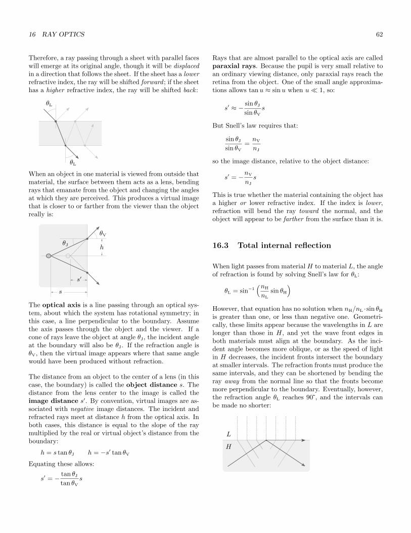
16 RAY OPTICS 62
Therefore, a ray passing through a sheet with parallel faceswill emerge at its original angle, though it will be displacedin a direction that follows the sheet. If the sheet has a lowerrefractive index, the ray will be shifted forward ; if the sheethas a higher refractive index, the ray will be shifted back :
θL
θL
When an object in one material is viewed from outside thatmaterial, the surface between them acts as a lens, bendingrays that emanate from the object and changing the anglesat which they are perceived. This produces a virtual imagethat is closer to or farther from the viewer than the objectreally is:
θV
θJ
s
s′
h
The optical axis is a line passing through an optical sys-tem, about which the system has rotational symmetry; inthis case, a line perpendicular to the boundary. Assumethe axis passes through the object and the viewer. If acone of rays leave the object at angle θJ, the incident angleat the boundary will also be θJ. If the refraction angle isθV, then the virtual image appears where that same anglewould have been produced without refraction.
The distance from an object to the center of a lens (in thiscase, the boundary) is called the object distance s. Thedistance from the lens center to the image is called theimage distance s′. By convention, virtual images are as-sociated with negative image distances. The incident andrefracted rays meet at distance h from the optical axis. Inboth cases, this distance is equal to the slope of the raymultiplied by the real or virtual object’s distance from theboundary:
h = s tan θJ h = −s′ tan θV
Equating these allows:
s′ = − tan θJ
tan θV
s
Rays that are almost parallel to the optical axis are calledparaxial rays. Because the pupil is very small relative toan ordinary viewing distance, only paraxial rays reach theretina from the object. One of the small angle approxima-tions allows tanu ≈ sinu when u� 1, so:
s′ ≈ − sin θJ
sin θV
s
But Snell’s law requires that:
sin θJ
sin θV
=nV
nJ
so the image distance, relative to the object distance:
s′ = −nV
nJ
s
This is true whether the material containing the object hasa higher or lower refractive index. If the index is lower,refraction will bend the ray toward the normal, and theobject will appear to be farther from the surface than it is.
16.3 Total internal reflection
When light passes from material H to material L, the angleof refraction is found by solving Snell’s law for θL:
θL = sin−1(nH
nL
sin θH
)However, that equation has no solution when nH/nL ·sin θH
is greater than one, or less than negative one. Geometri-cally, these limits appear because the wavelengths in L arelonger than those in H, and yet the wave front edges inboth materials must align at the boundary. As the inci-dent angle becomes more oblique, or as the speed of lightin H decreases, the incident fronts intersect the boundaryat smaller intervals. The refraction fronts must produce thesame intervals, and they can be shortened by bending theray away from the normal line so that the fronts becomemore perpendicular to the boundary. Eventually, however,the refraction angle θL reaches 90°, and the intervals canbe made no shorter:
L
H

16 RAY OPTICS 63
The incident angle θH that produces this is called the crit-ical angle:
θc = sin−1(nL
nH
)When the incident angle equals or exceeds the critical an-gle, refraction is no longer possible, and the ray is com-pletely reflected. This is called total internal reflection,and it occurs only when light passes from a higher refrac-tive index to a lower one. When the incident angle is justbelow the critical angle, some refraction occurs, but thelight is mostly reflected. As the incident angle decreases,more light is refracted, and less is reflected:
Total internal reflection allows fiber optic cable to trans-mit light impulses over hundreds of kilometers with littleintensity loss.
16.4 Scattering
Light may be scattered by dust or droplets suspended ina transparent medium. Because most such particles arelarge relative to the wavelength of light, the light is typi-cally reflected; if the particles are not colored, this producesa white haze in the medium, as in fog or clouds.
When light is scattered by particles much smaller than itswavelength, Rayleigh scattering results. The sun pro-duces a broad range of wavelengths, and when viewed fromspace, it is white. When the sun is high, molecules inthe atmosphere cause Rayleigh scattering, but this is mostlikely to affect smaller wavelengths. The sky appears bluebecause short wavelengths are scattered horizontally beforereaching the ground. The sun itself looks somewhat yellowbecause the blue and purple components have been partlylost. When the sun is very low, its light travels much far-ther through the atmosphere, and most of its blue light islost before it reaches the viewer. As a result, the sun ap-pears red, and any scattering that does occur at the endmust affect the remaining wavelengths, producing a red ororange sky.
16.5 Thin lenses
A focal point is one toward which rays that are parallelto the optical axis are made to converge, or one from whichthey are made to diverge. The focal length is the distancefrom the lens surface to a focal point. A focal plane isone that is parallel to the lens plane, and that contains afocal point.
Every lens has a lens plane that is centered between itsfaces and perpendicular to the optical axis. A lens usesrefraction to bend light rays, and this occurs at the lenssurface, which is some non-zero distance from the plane.A thin lens is one that is very thin relative to its focallength, and the object and image distances. In this type oflens, refraction can be assumed to occur in the lens plane,which simplifies calculations while introducing relativelylittle error.
The faces of a thin lens are almost parallel near the center,so rays passing through the center will not be bent. If thelens is assumed to have a zero width, they will not even bedisplaced, as normally happens when rays traverse a sheet:
A converging lens is thicker in the middle, so it bendsincoming parallel rays toward its far focal point, on the sidethat is away from the light source:
Such a lens also has a focal point on the near side, at thesame distance from the plane. If rays radiate from thispoint, they will be bent to produce parallel rays on the farside.
Every point on an object produces rays that travel in manydirections. When the object distance is greater than thefocal length, a converging lens causes these rays to meet ata point on its far side. This point is called the real imageof the object point:
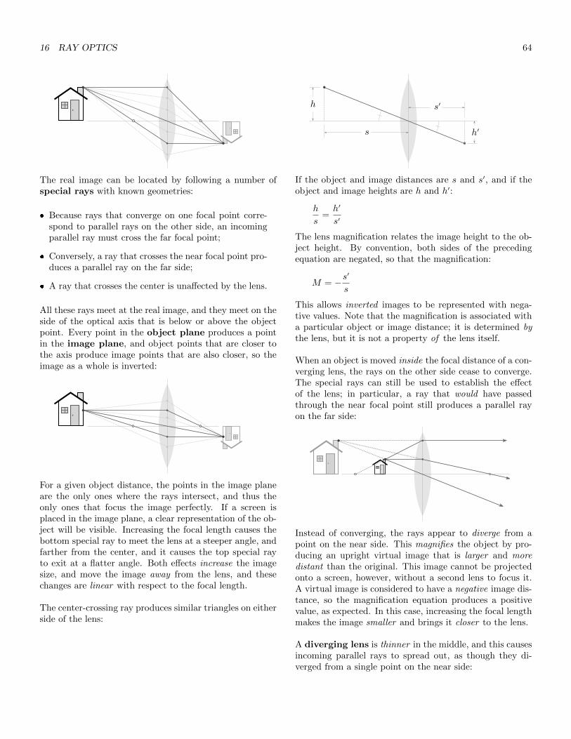
16 RAY OPTICS 64
The real image can be located by following a number ofspecial rays with known geometries:
� Because rays that converge on one focal point corre-spond to parallel rays on the other side, an incomingparallel ray must cross the far focal point;
� Conversely, a ray that crosses the near focal point pro-duces a parallel ray on the far side;
� A ray that crosses the center is unaffected by the lens.
All these rays meet at the real image, and they meet on theside of the optical axis that is below or above the objectpoint. Every point in the object plane produces a pointin the image plane, and object points that are closer tothe axis produce image points that are also closer, so theimage as a whole is inverted:
For a given object distance, the points in the image planeare the only ones where the rays intersect, and thus theonly ones that focus the image perfectly. If a screen isplaced in the image plane, a clear representation of the ob-ject will be visible. Increasing the focal length causes thebottom special ray to meet the lens at a steeper angle, andfarther from the center, and it causes the top special rayto exit at a flatter angle. Both effects increase the imagesize, and move the image away from the lens, and thesechanges are linear with respect to the focal length.
The center-crossing ray produces similar triangles on eitherside of the lens:
h
s h′
s′
If the object and image distances are s and s′, and if theobject and image heights are h and h′:
h
s=h′
s′
The lens magnification relates the image height to the ob-ject height. By convention, both sides of the precedingequation are negated, so that the magnification:
M = −s′
s
This allows inverted images to be represented with nega-tive values. Note that the magnification is associated witha particular object or image distance; it is determined bythe lens, but it is not a property of the lens itself.
When an object is moved inside the focal distance of a con-verging lens, the rays on the other side cease to converge.The special rays can still be used to establish the effectof the lens; in particular, a ray that would have passedthrough the near focal point still produces a parallel rayon the far side:
Instead of converging, the rays appear to diverge from apoint on the near side. This magnifies the object by pro-ducing an upright virtual image that is larger and moredistant than the original. This image cannot be projectedonto a screen, however, without a second lens to focus it.A virtual image is considered to have a negative image dis-tance, so the magnification equation produces a positivevalue, as expected. In this case, increasing the focal lengthmakes the image smaller and brings it closer to the lens.
A diverging lens is thinner in the middle, and this causesincoming parallel rays to spread out, as though they di-verged from a single point on the near side:

16 RAY OPTICS 65
The lens has a similar focal point on the far side, and itproduces a virtual image when the object is outside thefocal length:
The image position is determined much as before:
� Incoming parallel rays appear to diverge from the nearfocal point;
� Rays that would cross the far focal point produce par-allel rays on the far side;
� Rays that cross the center are unaffected.
Increasing the focal length of a diverging lens makes theimage larger and moves it farther from the lens.
Lenses can be placed in series so the real image projectedby one lens becomes the object of another. When this isdone, the second lens can be analyzed as though the pro-jected image were a physical object.
16.6 Spherical lenses
A lens can be modeled more accurately by understandingthat light refracts at the lens surface, rather than in thelens plane. Consider a refractive material with a sphericalface on one side. If an object is placed at point P in someless-refractive medium, then a ray that emanates from Pwill bend toward the normal when it reaches the boundary;if P is outside the focal point, this will return the ray to theoptical axis at point P ′. Every line that is normal to thespherical surface crosses the center of the sphere at pointC. The angle of incidence θJ is measured relative to thisline, as is the refraction angle θV. Because the refraction
angle is greater than zero, C must lie between the surfaceand P ′:
αP
h
C
P ′R
φ β
θV
ds′s
θJ
If the angle between the incident ray and the optical axisis α, and if the angle between the normal and the axis is φ,then the third angle in this triangle must equal π − φ− α.That angle and θJ must sum to π, so:
θJ = φ+ α
Similarly, if the angle between the refracted ray and theaxis is β, then the obtuse angle in that triangle must beπ−β− θV. That angle, when added to φ, must produce π,so:
θV = φ− β
Snell’s law requires that nJ sin θJ = nV sin θV. If the in-cident ray is paraxial, a small angle approximation allowsnJθJ ≈ nVθV, and:
nJ(φ+ α) = nV(φ− β)
Both triangles have altitude h, which produces a number ofright triangles. If the altitude meets the optical axis at dis-tance d from the surface, if the object and image distancesare s and s′, and if the sphere has radius R:
tanφ =h
R− dtanα =
h
s+ dtanβ =
h
s′ − d
The small angle approximations allow tanu ≈ u, and thesmallness of the angles also implies that d is very near zero.Therefore:
φ ≈ h
Rα ≈ h
sβ ≈ h
s′
nJ
( hR
+h
s
)= nV
( hR− h
s′
)and:
nJ
s+nV
s′=nV − nJ
R
This relates the image distance to the object distance andthe radius. The incident angle is not referenced, so allparaxial rays that emanate from object point P convergeat real image point P ′.
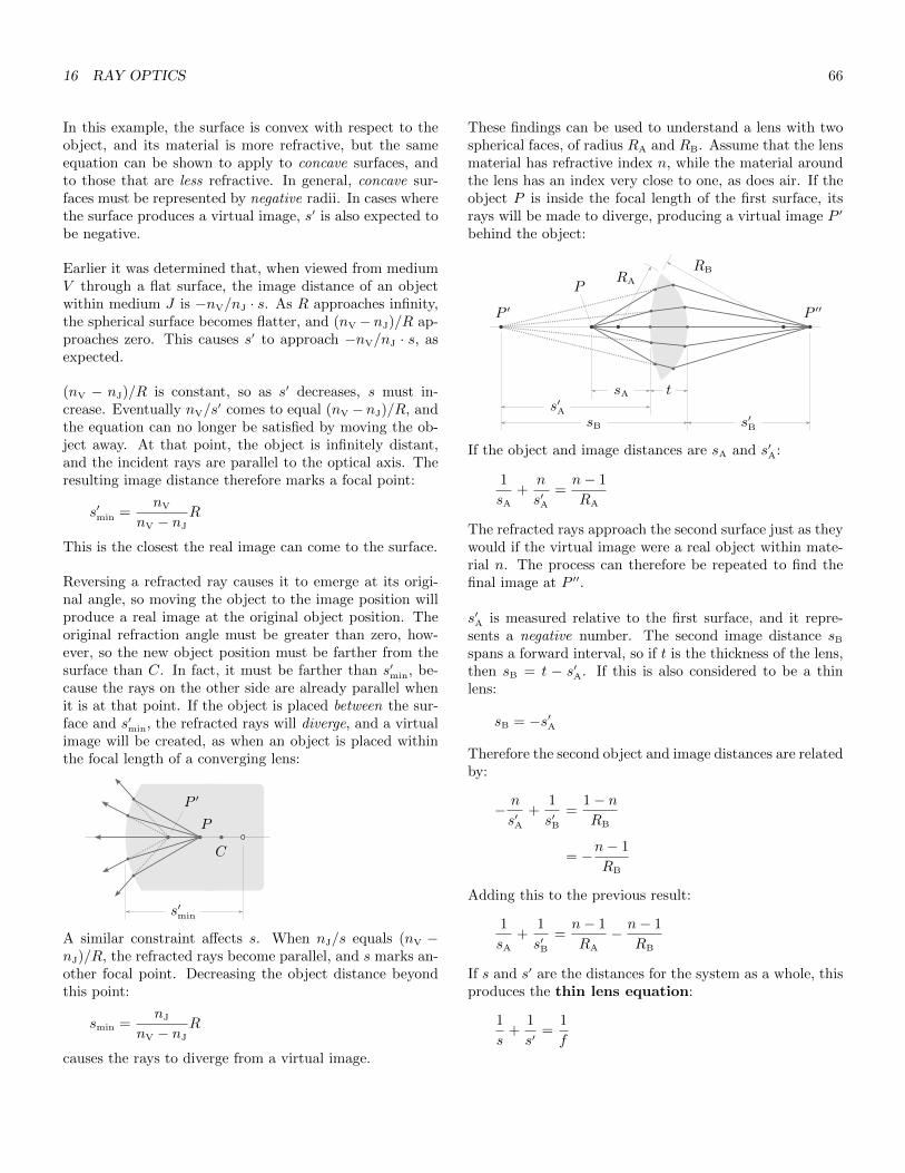
16 RAY OPTICS 66
In this example, the surface is convex with respect to theobject, and its material is more refractive, but the sameequation can be shown to apply to concave surfaces, andto those that are less refractive. In general, concave sur-faces must be represented by negative radii. In cases wherethe surface produces a virtual image, s′ is also expected tobe negative.
Earlier it was determined that, when viewed from mediumV through a flat surface, the image distance of an objectwithin medium J is −nV/nJ · s. As R approaches infinity,the spherical surface becomes flatter, and (nV −nJ)/R ap-proaches zero. This causes s′ to approach −nV/nJ · s, asexpected.
(nV − nJ)/R is constant, so as s′ decreases, s must in-crease. Eventually nV/s
′ comes to equal (nV − nJ)/R, andthe equation can no longer be satisfied by moving the ob-ject away. At that point, the object is infinitely distant,and the incident rays are parallel to the optical axis. Theresulting image distance therefore marks a focal point:
s′min =nV
nV − nJ
R
This is the closest the real image can come to the surface.
Reversing a refracted ray causes it to emerge at its origi-nal angle, so moving the object to the image position willproduce a real image at the original object position. Theoriginal refraction angle must be greater than zero, how-ever, so the new object position must be farther from thesurface than C. In fact, it must be farther than s′min, be-cause the rays on the other side are already parallel whenit is at that point. If the object is placed between the sur-face and s′min, the refracted rays will diverge, and a virtualimage will be created, as when an object is placed withinthe focal length of a converging lens:
C
P
P ′
s′min
A similar constraint affects s. When nJ/s equals (nV −nJ)/R, the refracted rays become parallel, and s marks an-other focal point. Decreasing the object distance beyondthis point:
smin =nJ
nV − nJ
R
causes the rays to diverge from a virtual image.
These findings can be used to understand a lens with twospherical faces, of radius RA and RB. Assume that the lensmaterial has refractive index n, while the material aroundthe lens has an index very close to one, as does air. If theobject P is inside the focal length of the first surface, itsrays will be made to diverge, producing a virtual image P ′
behind the object:
sB
P ′ P ′′
P
s′A
tsA
s′B
RBRA
If the object and image distances are sA and s′A:
1
sA
+n
s′A=n− 1
RA
The refracted rays approach the second surface just as theywould if the virtual image were a real object within mate-rial n. The process can therefore be repeated to find thefinal image at P ′′.
s′A is measured relative to the first surface, and it repre-sents a negative number. The second image distance sB
spans a forward interval, so if t is the thickness of the lens,then sB = t − s′A. If this is also considered to be a thinlens:
sB = −s′A
Therefore the second object and image distances are relatedby:
− n
s′A+
1
s′B=
1− nRB
= −n− 1
RB
Adding this to the previous result:
1
sA
+1
s′B=n− 1
RA
− n− 1
RB
If s and s′ are the distances for the system as a whole, thisproduces the thin lens equation:
1
s+
1
s′=
1
f

17 WAVE-PARTICLE DUALITY AND QUANTIZATION 67
with the focal length f being determined by the lensmaker’s equation:
1
f= (n− 1)
[ 1
RA
− 1
RB
]As expected, s approaches the focal length as s′ approachesinfinity, and vice versa.
In this example, the first surface is convex relative to theobject, and the second is concave, but the same equationcan be shown to apply to other configurations, if concaveradii are again represented with negative numbers. This in-cludes diverging lenses, meniscus lenses, which have radiithat are both convex or both concave, and even lenses withone flat surface, this being represented by an infinite radius.
16.7 Resolution
Because a material’s refractive index increases slightly aswavelengths get shorter, the focal length of a lens is some-what shorter for violet light than it is for red. The color-specific blurring this produces is called chromatic aber-ration.
When spherical lenses were analyzed in the thin lens equa-tion, the incident rays were assumed to be paraxial so thatsmall angle approximations could be used. Unless the ob-ject is very distant relative to the lens diameter, however,larger angles will be found near the outside of the lens,and some rays will be focused on slightly different points.This blurring effect is called spherical aberration, and itbecomes stronger as the lens diameter increases. Converg-ing lenses and diverging lenses produce offsetting effects,so spherical aberration can be largely canceled by placingthese in series.
Light can be modeled as a collection of rays, but it is still awave. A lens focuses the waves that pass through it, but italso acts as an aperture, diffracting the waves. As alreadyseen, when light passes through a circular aperture, it cre-ates a circular interference pattern called Airy’s disk. If ascreen is placed in the focal plane, the central maximum inthis pattern has width:
w ≈ 2.44λf
d
with d being the diameter of the lens. An object that isvery small or very distant would be expected to create avery small image, but w is not affected by the object size,it is determined only by the size of the aperture, the focallength, and the wavelength of the light. w is therefore the
minimum spot size that can be produced by a partic-ular optical system. It is difficult to produce a lens witha diameter greater than the focal length, so in practice,resolution is limited by the wavelength. Though spheri-cal aberration can be managed by placing lenses in series,or by using non-spherical lenses, this diffraction effect cannever be eliminated.
Rayleigh’s criterion can be used to determine whethertwo object points, such as distant stars, can be resolvedby a given system. The central maximum in Airy’s disk issurrounded by the first-order minimum, a dark ring wheredestructive interference occurs. The angular displacementof this minimum:
θ1 ≈ 1.22λ
d
According to Rayleigh’s criterion, two objects of equalbrightness are resolvable if their angular separation isgreater than or equal to θ1. For this reason, θ1 is consideredto be the angular resolution of an optical system.
17 Wave-particle duality andquantization
17.1 Spectroscopy
An optical spectrometer splits a single ray of light intodistinct spectral components. This can be accomplishedby focusing light onto a diffraction grating, which producesconstructive interference for specific components at specificangles. The spectrum is then focused onto a detector or aphotographic plate.
Different light sources produce different spectrum types.When matter is heated until it glows, it produces a con-tinuous spectrum containing smooth intensity variationsover a range of wavelengths. This type is produced by thesun or by incandescent lights. When gas is ionized to gen-erate light within a discharge tube, it produces a discretespectrum containing sharp, bright spectral lines at spe-cific wavelengths.
Different chemical elements produce different spectra whenexcited within a discharge tube. Hydrogen produces lineswith wavelength:
λ =91.19nm
1/m2 − 1/n2
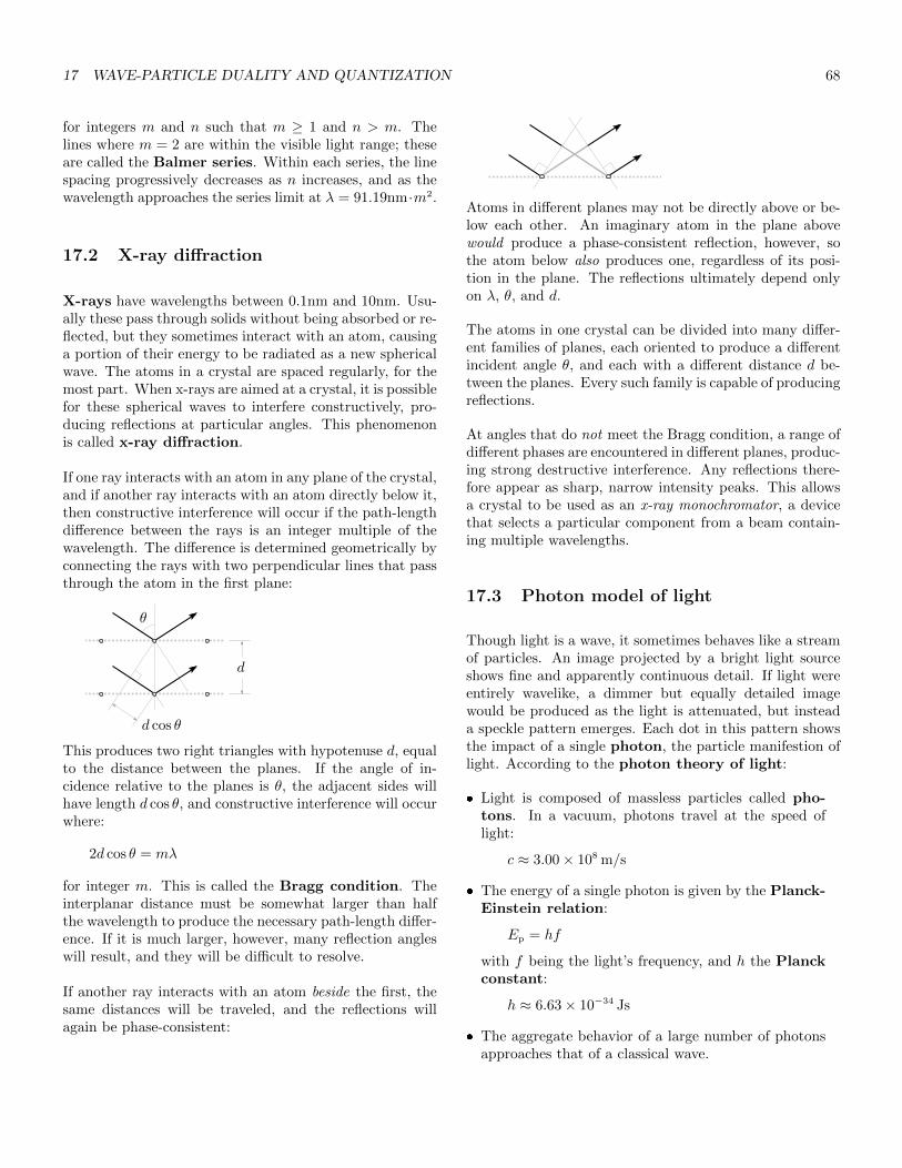
17 WAVE-PARTICLE DUALITY AND QUANTIZATION 68
for integers m and n such that m ≥ 1 and n > m. Thelines where m = 2 are within the visible light range; theseare called the Balmer series. Within each series, the linespacing progressively decreases as n increases, and as thewavelength approaches the series limit at λ = 91.19nm·m2.
17.2 X-ray diffraction
X-rays have wavelengths between 0.1nm and 10nm. Usu-ally these pass through solids without being absorbed or re-flected, but they sometimes interact with an atom, causinga portion of their energy to be radiated as a new sphericalwave. The atoms in a crystal are spaced regularly, for themost part. When x-rays are aimed at a crystal, it is possiblefor these spherical waves to interfere constructively, pro-ducing reflections at particular angles. This phenomenonis called x-ray diffraction.
If one ray interacts with an atom in any plane of the crystal,and if another ray interacts with an atom directly below it,then constructive interference will occur if the path-lengthdifference between the rays is an integer multiple of thewavelength. The difference is determined geometrically byconnecting the rays with two perpendicular lines that passthrough the atom in the first plane:
d
d cos θ
θ
This produces two right triangles with hypotenuse d, equalto the distance between the planes. If the angle of in-cidence relative to the planes is θ, the adjacent sides willhave length d cos θ, and constructive interference will occurwhere:
2d cos θ = mλ
for integer m. This is called the Bragg condition. Theinterplanar distance must be somewhat larger than halfthe wavelength to produce the necessary path-length differ-ence. If it is much larger, however, many reflection angleswill result, and they will be difficult to resolve.
If another ray interacts with an atom beside the first, thesame distances will be traveled, and the reflections willagain be phase-consistent:
Atoms in different planes may not be directly above or be-low each other. An imaginary atom in the plane abovewould produce a phase-consistent reflection, however, sothe atom below also produces one, regardless of its posi-tion in the plane. The reflections ultimately depend onlyon λ, θ, and d.
The atoms in one crystal can be divided into many differ-ent families of planes, each oriented to produce a differentincident angle θ, and each with a different distance d be-tween the planes. Every such family is capable of producingreflections.
At angles that do not meet the Bragg condition, a range ofdifferent phases are encountered in different planes, produc-ing strong destructive interference. Any reflections there-fore appear as sharp, narrow intensity peaks. This allowsa crystal to be used as an x-ray monochromator, a devicethat selects a particular component from a beam contain-ing multiple wavelengths.
17.3 Photon model of light
Though light is a wave, it sometimes behaves like a streamof particles. An image projected by a bright light sourceshows fine and apparently continuous detail. If light wereentirely wavelike, a dimmer but equally detailed imagewould be produced as the light is attenuated, but insteada speckle pattern emerges. Each dot in this pattern showsthe impact of a single photon, the particle manifestion oflight. According to the photon theory of light:
� Light is composed of massless particles called pho-tons. In a vacuum, photons travel at the speed oflight:
c ≈ 3.00× 10⁸ m/s
� The energy of a single photon is given by the Planck-Einstein relation:
Ep = hf
with f being the light’s frequency, and h the Planckconstant:
h ≈ 6.63× 10⁻³⁴ Js
� The aggregate behavior of a large number of photonsapproaches that of a classical wave.

18 ELECTRIC CHARGE 69
Paradoxically, light’s wavelike qualities persist even in itsparticle manifestation. The double-slit experiment showsthe wavelike nature of light by diffracting the output of asingle light source at two narrow openings. When the lightis relatively intense, smooth gradations are seen in the in-terference pattern that results. If the light is greatly atten-uated, a speckle pattern emerges, yet the dots still conformon average to the original interference pattern. This hap-pens even when photons traverse the system one at a time,implying that each single photon passes though both slitsand interferes with itself before reaching the screen.
17.4 Matter waves
Just as light waves sometimes resemble particles, particlesof matter sometimes resemble waves. If a beam of elec-trons is aimed at a crystal, and if all the electrons travel atthe same speed, they will reflect at angles consistent withthe Bragg condition, for some wavelength. This impliesthat the electrons have reflected and superposed as a waveto produce constructive and destructive interference, justas light does during x-ray diffraction. If the speed of theelectrons is changed, the reflection angles will change also,but every angle will again be consistent with the Braggcondition for some wavelength.
It can be shown that the wavelength of these matterwaves:
λ =h
p
This is called the de Broglie wavelength. p is the parti-cle’s momentum, so massive or fast-moving particles havesmaller wavelengths. Particles or objects of any size canbe analyzed as matter waves, but larger objects have wave-lengths that are too small to produce wave phenomena inreal conditions.
At the quantum scale, the wavelike nature of matter in-troduces constraints that are not seen in classical systems.Assume that a particle of mass m is bouncing between thewalls of a container with length L. This is called the ‘parti-cle in a box’ model. If the collisions are perfectly elastic,the particle will bounce indefinitely, and its waveform willoverlap itself to produce a standing wave.
As already seen, a standing wave with fixed points at zeroand L has wavelength λn = 2L/n, for some integer n > 0.From this it follows that:
h
pn=
2L
n
so that:
pn =( h
2L
)n
The particle’s momentum is therefore quantized by incre-ments that grow larger as the container becomes smaller.Because kinetic energy E = p2/2m:
En =(h/2L)2n2
2m=
h2
8mL2n2
so the particle’s energy is also quantized. n is called thequantum number, and En is the energy level of theparticle. The energy quanta become smaller as m and Lincrease.
The standing wave can be no less than half a wavelengthlong, so n can be no less than one, and the particle’s kineticenergy cannot be less than E1. As a result, the particle cannever be at rest. The energy level can be expressed relativeto this least energetic state:
En = n2E1
18 Electric charge
An atomic nucleus is around 10−14 m in diameter. Sur-rounding the nucleus is an electron cloud with a diam-eter of approximately 10−10 m. Electrons are often saidto ‘orbit’ the nucleus, but wave-particle duality preventsthem from following specific trajectories over such a smalldistance.
Electric charge is a property of protons and electrons,and is found nowhere else. The proton has a mass of1.67 × 10−27 kg, and it carries a positive charge, knownas the fundamental unit of charge:
e = 1.60× 10⁻¹⁹ C
The electron has a much smaller mass of 9.11 × 10⁻³¹ kg,but it carries an equal negative charge, −e. As will beseen, every charge produces electrostatic forces that repellike charges and attract opposite ones. A charge’s effect onother charges is described by its electric field.
An object’s charge is determined solely by the number ofprotons Np and electrons Ne it contains:
q = (Np −Ne)e
Charge is therefore quantized. An object with no net chargeis electrically neutral.

18 ELECTRIC CHARGE 70
Protons are not readily added to or removed from nuclei,so objects become charged by gaining or losing electrons.The gain or loss of electrons by a single atom is calledionization. The law of conservation of charge holdsthat charge cannot be created or destroyed, it can only betransferred between objects.
The electrons in the outer shell of an atom are called va-lence electrons. In metals, valence electrons are looselybound to their nuclei. This creates a ‘sea of electrons’around the positively-charged ion cores that contain thenuclei and non-valence electrons. The aggregate movementof charges through a material is called current. A chargethat physically moves is called a charge carrier. In met-als, electrons serve as charge carriers, and their free move-ment makes metals electrically conductive. Ionic solutionsare also conductive, but their charge carriers are ions. Itis not necessary for any charge carrier to travel the fulllength of the conductor; a most carriers travel only a shortdistance, advancing the charge incrementally and causingother carriers to be displaced in turn.
The valence electrons in an insulator are tightly bound totheir nuclei. An insulator’s surface can be rubbed to pro-duce a charge, particularly if either material contains com-plex organic molecules, which are easily broken to producemolecular ions. The charge cannot move, so it remains onthe surface, in the area that was rubbed.
Charges propagate very quickly in a conductor, and an iso-lated conductor soon reaches electrostatic equilibrium,where the net force on every charge is zero, and all chargesare at rest. If the object contains more electrons than pro-tons, or vice versa, these excess charges will move awayfrom each other, and, as the conductor reaches equilibrium,they will spread across its surface.
If a charged object touches an uncharged conductor, thecharge will be shared between them, at least partly dis-charging the first object. A conductor that is groundedshares its charge with the entire earth, allowing it to ab-sorb a charge of any practical size. Humid air is a poorconductor, but it will also discharge an object over time.
If a charged object is placed near an uncharged conductor,some opposite charges in the conductor will be drawn to-ward the object, and some like charges will be pushed away.This is called charge polarization. The object must nottouch the conductor or it will be discharged. The force thatattracts opposite and repels like charges decreases withdistance. Because the opposite charges are closer to thecharged object, this creates a polarization force that at-tracts the conductor, even though it is electrically neutralas a whole.
If a charged object is used to polarize a neutral conductor,and if the opposite side of the conductor is momentarilygrounded, the excess charge on that side will be discharged.When the object is moved away, the conductor will be leftwith a net charge opposite that of the object. This is calledcharge by induction.
Insulators cannot be polarized in the aggregate becausethey do not contain mobile charge carriers. Individualatoms can be polarized by displacing their electron cloudsin one direction and their nuclei in the other. Two op-posite and slightly separated charges are called an elec-tric dipole, and these also produce a polarization force.Placing a charged object near an insulator creates induceddipoles. Water, by contrast, has a molecular structure thatacts as a permanent dipole. Because electrostatic forcedecreases with distance, the near charges in the dipolesattract slightly more than the far charges repel, and theobject as a whole is pulled toward the charge.
Like other gases, air is an insulator, but it normally con-tains small numbers of electrons that have been freedby background radiation. In the presence of a strongelectric field, these can accelerate quickly before strikingother molecules. In air, if an electron’s kinetic energy is2.0 × 10−18 J or more, another electron will be freed bythe collision, then both will be accelerated again, poten-tially yielding an exponential proliferation of charge carri-ers. This is called electrical breakdown, and it allowsgases to conduct electricity. When the free electrons re-join the ionized nuclei, they emit light. Sparks, arcing,and lightning are all examples of electrical breakdown, anddischarge tubes use it to produce light. Other electricalbreakdown processes can occur in solids and liquids.
18.1 Coulomb’s law
A point charge represents an idealized charged object; ithas charge and mass, but no size. Two objects can be rep-resented with point charges if they are both much smallerthan the distance that separates them.
Given two static point charges qA and qB, separated by dis-tance r, the magnitude of the electrostatic force actingon either is given by Coulomb’s law:
F =K|qA||qB|
r2
K is the electrostatic constant:
K ≈ 8.99× 10⁹ Nm2/C2

18 ELECTRIC CHARGE 71
The force is directed along the line that joins the points,with opposite charges attracting, and like charges repelling.The SI unit of charge is the coulomb, C. ThoughCoulomb’s law applies specifically to static charges, it ap-proximates the force between moving charges if their rela-tive speed is much less than the speed of light.
As will be seen, electric flux describes the strength of theelectric field passing through a surface. A medium’s per-mittivity determines the amount of charge needed to pro-duce flux, with lower permittivity values producing greateramounts. The lowest possible permittivity is the vacuumpermittivity, also called the permittivity of free space orthe permittivity constant :
ε0 =1
4πK≈ 8.85× 10⁻¹² C2/Nm2
This constant allows Coulomb’s law to be expressed as:
F =1
4πε0· |qA||qB|
r2
18.2 Electric fields
Though the elements in a charge pair interact to producethe electrostatic force, it is common for one to be desig-nated as the source charge. Its contribution is repre-sented as an electric field that can be combined withanother charge to determine the force. If the source is apoint charge Q at the origin, the field:
~E =1
4πε0· Qr2r
Electric field strength is measured in N/C. Given a second,
positive charge q within ~E, the force on q:
~F = q ~E
If Q is positive, the field will point away from the origin,like r. Because q is also positive, the direction of ~F willmatch that of ~E, and the charges will repel, as expected. Ifexactly one of the charges were negative, the field strengthwould be negative, and the field would be understood topoint toward the origin.
Though dipoles are neutral as a whole, they do produceelectric fields. Assume that dipole charges q and −q areseparated by distance s, and that they lie along the y-axis,with the dipole’s center at the origin. If q is above −q, apositive charge that is itself above q will be repelled by thepositive pole more than it is attracted by the negative, andone below −q will be attracted more than repelled. There-fore, the field will point up wherever the y-axis is greater
than s/2 or less than −s/2. It will point down betweenthose points.
When charges combine to produce a field, the field valueat any point is equal to the vector sum of the values pro-duced by the various charges. Along the y-axis, each vectorhas only one spatial component, so the vector sum can berepresented with a single number. For points outside thedipole, the total field strength:
Ea:dip =q
4πε0
[ 1
(y − 12s)2− 1
(y + 12s)2
]=
q
4πε0
[ 2sy
(y − 12s)2(y + 1
2s)2
]Note that this gives the length of the field vector, which bydefault points away from the source charges. The positiveand negative signs in the total field strength do not cor-relate directly with the acceleration expected of a chargein this field; in particular, the negative values below thedipole do not indicate that a positive charge would accel-erate in the negative direction. Instead, every positive fieldstrength above indicates a vector that points away, and ev-ery negative strength below indicates one that points to-ward. The field and the acceleration therefore point upeverywhere along the axis.
If the dipole length s is very small relative to the chargedistance y, this reduces to:
Ea:dip ≈1
4πε0· 2qs
y3
The dipole moment ~p represents the polarity or sepa-ration of charge in a dipole. It points from the negativecharge to the positive, and it has magnitude p = qs, mea-sured in Cm.
Because the field always points up, the direction can be in-dicated by ~p, and the signed value y can be replaced with r,the unsigned distance from the center of the dipole. There-fore, the charge along the dipole axis:
~Ea:dip =1
4πε0· 2~p
r3
This would not produce a correct direction or magnitudebetween the charges, but it has already been assumed thatr is far outside the dipole. Because each charge is partiallycanceled by the other, the field strength decreases with thecube of the distance, rather than the square, as it would fora point charge.
Consider the perpendicular plane that bisects the dipole.If a given point on this plane is assumed to lie along the

18 ELECTRIC CHARGE 72
x-axis, the field at that point can be divided into x and ycomponents:
y
x
12s
~Eq~E−q
~Ep:d
d
−q
q
θ
The point is equidistant from each charge, so the x com-ponents cancel, the y components combine, and the fieldpoints down everywhere in the plane.
The point, the origin, and charge q combine to form a righttriangle with hypotenuse d. The strength of the q field:
Eq =1
4πε0· qd2
If θ is the angle between the hypotenuse and the x-axis,the y component of the q field:
Ey:q = Eq sin θ
Because:
sin θ =1
2s/d and d =
√x2 +
(1
2s)2
Ey:q can be expressed in terms of s and x:
Ey:q =1
4πε0· q
x2 + ( 12s)2·
12s√
x2 + ( 12s)2
Charge −q produces an equal y component, so the dipolefield as a whole, throughout the bisecting plane:
Ep:dip =1
4πε0· qs[x2 + ( 1
2s)2
]3/2
If s is again assumed to be very small relative to x, and ifx is replaced with r, the distance to the dipole center, thenthe charge in the plane that bisects the dipole:
~Ep:dip ≈ −1
4πε0· ~pr3
The value is negated because ~p points toward the positivecharge, yet the field in this plane points down.
A field’s structure can be visualized with field lines thatshow its direction and general magnitude within a planecontaining the charges:
Each line starts at a charge. The line is drawn by follow-ing the field’s direction, which leads eventually to another,opposite charge, or away from the charges and to infinity.A tangent to any line shows the field’s direction; since thisis unique at a given point, the lines can never cross. Thelines are marked with arrowheads that point away from thepositive charge and toward the negative. The number oflines in an area correlates roughly with the strength of thefield.
18.3 Uniform charge distributions
Consider a thin rod bearing charge Q that is uniformlydistributed over its length. Within the perpendicular planethat bisects the rod, the field can be calculated much asit was for the dipole. If the rod is aligned with the y-axis and centered on the origin, any point in the plane canbe assumed to lie along the x-axis. Because the charge isuniform, the rod can be divided into a number of smallsections, each carrying charge ∆Q. Every section above ismatched by another below that is the same distance fromthe plane; because these bear the same charge, their y com-ponents cancel, and their x components add. Summing thex component for each section gives the field as a whole.
The section at yi combines with the origin and the planepoint to form a right triangle with hypotenuse di. If thesection acts as a point charge, and if θi is the angle at thepoint, the section’s x field component:
Ex:i =1
4πε0· ∆Q
d2i
cos θi
To integrate, it is necessary to express the function in termsof y. Because cos θi = x/di and di =
√x2 + y2
i :
Ex:i =1
4πε0· ∆Q
x2 + y2i
· x√x2 + y2
i
=1
4πε0· x∆Q
(x2 + y2i )
3/2

18 ELECTRIC CHARGE 73
Summing to produce the magnitude of the entire field:
Ep:rod =1
4πε0
∑i
x∆Q
(x2 + y2i )
3/2
∆Q must also be related to y. Given rod length L, thelinear charge density:
λ =Q
L
so that ∆Q = λ∆y. Therefore:
Ep:rod =λ
4πε0
∑i
x∆y
(x2 + y2i )
3/2
=λ
4πε0
∫ 12L
− 12L
x
(x2 + y2)3/2dy
This integral can be solved with trigonometric substitu-tions. If u = arctan(y/x), then y = x tanu and dy =x sec2 udu:∫ b
a
x
(x2 + y2)3/2dy =
∫ y=b
y=a
x2 sec2 u
(x2 + x2 tan2 u)3/2du
=
∫ y=b
y=a
x2 sec2 u((x2)(1 + tan2 u)
)3/2 du
=
∫ y=b
y=a
x2 sec2 u
x3 sec3 udu
=
∫ y=b
y=a
1
xcosu du
=1
xsinu
∣∣∣y=b
y=a
arctan(y/x) returns the angle at the point, so it turns outthat u = θ. Because sin θ = y/
√x2 + y2:
Ep:rod =λ
4πε0· y
x√x2 + y2
∣∣∣ 12L− 1
2L
=λ
4πε0· L
x√x2 + ( 1
2L)2
Finally, λL = Q, so the field strength in the plane thatbisects the rod, at distance r from the rod’s center:
Ep:rod =1
4πε0· Q
r√r2 + ( 1
2L)2
This can be used to determine the field around a straightline of charge with infinite length:
Eline =1
4πε0· limL→∞
Q
r√r2 + ( 1
2L)2
=1
4πε0· Q
r · 12L
=λ
2πε0r
This is a good approximation for the field near a straightwire, except near the ends.
Consider the field along the axis passing through a ringof charge with radius R. If the ring is centered on theorigin within the yz plane, each point on the x-axis hasthe same distance d from every point on the ring. Becausethe field produced by a given ring section is balanced bythe section opposite, the y and z components cancel. Thex component:
Ex:i =1
4πε0· ∆Q
d2cos θ
=1
4πε0· ∆Q
x2 +R2· x√
x2 +R2
so that:
Ea:ring =1
4πε0· x
(x2 +R2)3/2
∑∆Q
∆Q is constant, so the sections can be summed withoutintegration. At distance r, the axial field strength for thering as a whole:
Ea:ring =1
4πε0· rQ
(r2 +R2)3/2
This can be extended to a disk of charge. By dividingthe disk into a set of rings, each with radius si, the axialfield strength:
Ea:disk =r
4πε0
∑i
∆Qi
(r2 + s2i )
3/2
The surface charge density of area A:
η =Q
A
so ∆Q = η∆A. Because ∆A = 2πsi∆si:
∆Q = 2πηsi∆si
and:
Ea:disk =ηr
2ε0
∑i
si∆si(r2 + s2
i )3/2

18 ELECTRIC CHARGE 74
=ηr
2ε0
∫ R
0
s
(r2 + s2)3/2ds
If u = r2 + s2 and du = 2sds:
Ea:disk =ηr
4ε0
∫ r2+R2
r2
1
u3/2du
= − ηr2ε0· 1√
u
∣∣∣r2+R2
r2
= − ηr2ε0
( 1√r2 +R2
− 1
r
)Therefore, the field strength of a disk of charge, at distancer along the axis:
Ea:disk =η
2ε0
(1− r√
r2 +R2
)It is expected that the field will approximate that of a pointcharge when r is large relative to the disk radius R. Of-ten this can be verified by calculating the limit of the fieldstrength as r approaches infinity, but in this case, that limitis zero. However, after factoring r from the denominator:
Ea:disk =η
2ε0
(1− 1√
1 +R2/r2
)The binomial approximation allows:
(1 + x)α ≈ 1 + αx
when |x| < 1 and |αx| � 1, so that:
Ea:disk ≈η
2ε0
(1−
[1 +
(− 1
2· R
2
r2
)])=
η
2ε0
(1
2· R
2
r2
)=
ηR2
4ε0r2
when r � R. ηR2 = Q/π, so the field strength at a greatdistance:
Ea:disk ≈1
4πε0· Qr2
as expected.
The field strength for a plane of charge is found by lettingthe disk radius R approach infinity. At any point outsidethe plane:
Eplane =η
2ε0
Note that the strength is constant everywhere outside theplane.
A parallel-plate capacitor is constructed from two flatconductive surfaces with a non-conductive material be-tween. As a charge forms on one plate, an equal and oppo-site charge forms on the other. Because the plates are veryclose, each can be modeled as a simple plane of charge.Each field radiates in both directions, overlapping insideand outside the capacitor. Inside, the fields point in thesame direction, from the positive to the negative, so thefield strength is twice that produced by a single plane:
Ecap =η
ε0=
Q
ε0A
Outside, the fields point in opposite directions, away fromthe positive and toward the negative. In an idealized capac-itor, these cancel; in practice, a fringe field is produced,especially near the edges.
18.4 Motion of charged objects
Given a particle with charge q and mass m, its accelerationwithin electric field ~E:
~a =~F
m=
q
m~E
The magnitude of the acceleration is determined by thecharge-to-mass ratio q/m.
A field with the same direction and magnitude at everypoint is called a uniform electric field. This must be dis-tinguished from a uniform charge distribution, which couldproduce a uniform field, but often won’t. As expected, acharged particle experiences constant acceleration in a uni-form field.
Because there is no gradient, no net force is exerted on adipole in a uniform field, but it is subject to a polarizingtorque. Equal and opposite forces apply to the charges, sothe dipole acts as a force couple. If the dipole’s length is s,and if the angle between that length and the lines of actionis θ, then the distance between the lines l = s sin θ:
~F−
θ
~F+
ls

19 GAUSS’ LAW 75
Therefore, the magnitude of the torque:
τ = lF = s sin θ · qE
The magnitude of the dipole moment p = qs, so:
τ = pE sin θ
In general, if ~r is the displacement from a pivot to the pointof application, then ~τ = ~r × ~F , so that:
~τ = q~r ×~F
q= ~p× ~E
19 Gauss’ law
The electric flux Φ is the total strength of the electric fieldpassing through some surface; it is measured in Nm2/C.For a given field, the flux varies with the area and orienta-tion of the surface; larger surfaces collect more of the field,as do those that are more perpendicular to it, since thesehave larger cross-sectional areas relative to its direction.
A uniform electrical field ~E can be decomposed into twocomponents, one parallel to the surface, and one perpen-dicular. The parallel component does not pass throughthe surface at all. If θ is the angle between ~E and unitvector n that is normal to the surface, the perpendicularcomponent:
E⊥ = E cos θ
Therefore, the flux in a uniform field:
Φ = EA cos θ
If the surface is represented by area vector ~A = An:
Φ = ~E · ~A
In a non-uniform field, if ~Ei is the strength at a point onthe surface, and if (δ ~A)i is the infinitesimal area at thatpoint, the flux through the point:
Φi = ~Ei · (δ ~A)i
The flux through the entire surface is given by the surfaceintegral:
Φ =∑i
~Ei · (δ ~A)i =
∫~E · d ~A
A closed surface is one that completely divides an in-side volume from the outside. A Gaussian surface is a
closed surface with an electric field passing through it. Theflux through such a surface is given by the closed surfaceintegral:
Φ =
∮~E · d ~A
This is calculated like any other integral; the circle over theintegral sign merely indicates that the surface is closed. d ~Ais assumed to point from inside to outside.
If a point charge is centered within a spherical Gaussiansurface, its field will be constant in strength everywhere onthe surface, and normal to the surface as well. Therefore:
Φ =
∮~E · d ~A = E
∮dA = EA
with A being the total area of the surface. If Q is the sourcecharge, and r the sphere’s radius:
E =1
4πε0· Qr2
A = 4πr2
E decreases as r increases, but A increases by a likeamount, so that:
Φ =
∮~E · d ~A =
Q
ε0
This is called Gauss’ law.
The flux through a small area is constant for any radius, sothe law applies to closed surfaces of any shape, since thesecan always be modeled as a collection of narrow radial sec-tions of varying length. Complex surfaces may require thatsections exit and re-enter the volume one or more times.These also conform to Gauss’ law, since exiting producesoutward-pointing d ~A, entering produces inward -pointingd ~A, and each section necessarily exits the volume once morethan it enters.
Similarly, charges outside a closed surface produce flux atspecific intersection points, but they contribute nothing tothe total flux, since the number of entrances always equalsthe number of exits. Therefore, the total flux through aclosed surface that contains no net charge must be zero.
Finally, because the shape of the surface can vary, acharge’s location can vary as well. Gauss’ law thereforeapplies to collections of charges within the surface, regard-less of their distribution, with the total charge being givenby Q.
19 GAUSS’ LAW 76
19.1 Symmetric charge distributions
A shape is symmetric if it is unchanged after one or moregeometric transformations. In particular:
� It has translation symmetry along a given axis if itis unchanged after being moved along that axis;
� It has rotation symmetry about an axis if it is un-changed after being rotated about that axis;
� It has reflection symmetry relative to a plane if itis unchanged after each point is moved to the samedistance from the other side of the plane.
A symmetric charge distribution produces a field with thesame symmetry. No vector in a symmetric field can havea component that is inconsistent with the field’s symme-try; therefore, the field produced by a spherical distributionmust point toward or away from the center, since a tan-gential component would change direction when reflected.
Because it shows the total flux through a surface, Gauss’law can be used to find the field strength through each point,if it can be shown that the field has the same strength ev-erywhere on the surface, and if it is always normal to thesurface.
If a charge distribution has spherical symmetry, a spherecentered on the distribution will meet both these criteria.Consider a spherical shell of charge. For a Gaussiansurface inside the shell, the total flux must be zero. Be-cause it is required to have the same direction and magni-tude everywhere on the surface, the field must also be zeroeverywhere inside a spherical shell.
Note that, although charges outside a Gaussian surface donot add to the total flux, they do produce non-zero fieldvalues at specific points if the charge distribution lacks thenecessary symmetry. Gauss’ law merely requires that suchcharges produce offsetting values at other points so thatthe flux as a whole is zero.
More generally, the field produced by a symmetric distri-bution is determined by dividing the total flux through thesurface by its area. The area of a sphere is 4πr2, so if Q isthe charge contained by that sphere:
Esph =Φ
A=Q/ε04πr2
Therefore, the field produced by a sphere of charge, orany other distribution with spherical symmetry:
~Esph =1
4πε0· Qr2r
For a given r, this matches the field produced by a pointcharge, though Q will vary with r if the radius is not out-side the distribution as a whole.
Given a uniform sphere of charge with radius R, the fieldinside the sphere at distance r varies with the amount ofcharge contained by r. The spherical shell outside r pro-duces no inside field, as already demonstrated. If Qr andVr are the charge and volume contained by radius r, and ifQ and V are the charge and volume of the distribution asa whole:
Qr
Q=VrV
=43πr3
43πR3
so that:
Qr =r3
R3Q
By Gauss’ law:
Ein:sph · 4πr2 =(r3/R3)Q
ε0
so the field inside the uniform sphere of charge:
~Ein:sph =1
4πε0· QR3
r · r
As r increases, the charge near the center has less effect,but much more charge is encompassed by the new volume.Therefore, though the strength of this field outside the dis-tribution decreases with the square of the distance, it in-creases linearly with distance inside.
As already seen, the field produced by a line of charge canbe derived from Coulomb’s law after a difficult integralsubstitution. With Gauss’ law, it is calculated more easily.If the line has linear charge density λ, and if a section oflength L is enclosed by a cylinder, the total charge withinQ = λL. The field is normal to the outside surface andequally strong at all points, while the flat surfaces at theends are parallel to the field, allowing them to be ignored.Because the outside area A = 2πrL:
Eline =Q/ε0A
=λL/ε02πrL
=λ
2πε0r
as expected.
The field produced by a plane of charge is found in likemanner. If a cylinder passes halfway through the plane,and if its axis is perpendicular to it, a disk of charge will befound within. Given cylinder radius R and surface chargedensity η, the contained charge Q = 2πR2η. The ends of

A MEASUREMENT 77
the cylinder are normal to the field, and their total surfacearea is 4πR2. The walls of the cylinder are parallel, so theyadd no flux. The field strength:
Eplane =Q/ε0A
=2πR2η/ε0
4πR2=
η
2ε0
as expected.
19.2 Conductors in electrostaticequilibrium
When a conductor reaches electrostatic equilibrium, thefield strength everywhere inside drops to zero. Conduc-tors contain an abundance of charge carriers, so if the fieldwere non-zero, some charges would move; in particular,if the field strength were positive, some positive chargeswould follow the field, or some negative charges wouldmove into it, and the positive concentration would be dis-persed or canceled. In this sense, every electric field directscharges toward an equilibrium that dissipates the field, ifthe charges are mobile. Because there is no field, the fluxthrough all points of a Gaussian surface that is anywhereinside the conductor is also zero, implying that the con-ductor’s interior is electrically neutral. Any excess chargemust therefore be found on the surface. Furthermore, theelectric field on the surface must at every point be directedoutward, and it must be normal to the surface, since anytangential component would produce a current that wouldrearrange the charges.
The same reasoning applies to fields produced by externalcharges. Such a field must be normal to the surface of theconductor, and it must end at that surface. A metal boxcan therefore be used to screen an external electric fieldfrom its interior. Wire cages are also reasonably effective.
Though it is likely to vary at different points, the fieldstrength at the surface can be related to the surface chargedensity η at each point. If a small cylinder passes halfwaythrough the surface, and if its axis is perpendicular to thesurface, a disk of area A and charge Q = ηA will be en-closed. This resembles the process used to analyze a planeof charge, but in that case, the field pointed outward onboth sides. This field has been shown to point outwardonly, so the field strength at the surface of the conductor:
Esurf:conduct =ηA/ε0A
=η
ε0
A Measurement
Accuracy describes the proximity of a measurement to thequantity being measured. Precision describes the proxim-ity of repeated measurements to each other.
Systematic errors shift measurements in a consistent di-rection. These affect the accuracy of a measurement, butnot its precision. Random errors impart no predictablebias. These affect precision, but over repeated trials, theyhave no effect on accuracy.
The least count of a measuring device is the smallest unitgradation offered by that device. When taking measure-ments, it is customary to record all decimal places up tothe least count, plus an estimated digit. This establishesthe number of significant digits in the measurement.
When reading values, zeroes to the left of the first non-zerodigit are not counted as significant digits. If a decimal pointis given, all trailing zeros are considered significant. If thereis no decimal point, the significance of trailing zeroes is notdefined, though they can generally be considered insignif-icant. Values that are defined rather than measured canbe considered to have an unlimited number of significantdigits.
The result of a calculation should not have more significantdigits than the least precise measurement used, though itis customary to retain an extra digit if the result beginswith one. It is permissible to retain one or two extra digitsfor intermediate calculations.

B VECTORS 78
SI units take their name from Le Systeme Internationald’Unites. Common prefixes include:
Factor Prefix Symbol
1018 exa E1015 peta P1012 tera T109 giga G106 mega M103 kilo k102 hecto h101 deka da· · · · · · · · · · · · · · · · · · · · ·
10−1 deci d10−2 centi c10−3 milli m10−6 micro µ10−9 nano n10−12 pico p10−15 femto f10−18 atto a
B Vectors
By convention, vectors are not allowed to have negativemagnitudes; if such a result is produced, the vector is in-stead made to point in the opposite direction.
In the rectangular coordinate system, a vector ~A may bedecomposed into component vectors ~Ax, ~Ay, and ~Azwhich are parallel to the axes. These may be describedby their components Ax, Ay, and Az, which can havenegative values.
The unit vectors ı, , and k have unit magnitudes thatcoincide with the positive x, y, and z axes. Therefore:
~A = Ax ı+Ay +Azk
B.1 Dot products
If the counterclockwise angle from ~A to ~B is θ, the vectors’dot product or scalar product:
~A · ~B ≡ AB cos θ
Since the dot product of a unit vector with itself is one, andthe dot product of any vector with an orthogonal vector is
zero, this gives the sum of the products of the correspond-ing components:
~A · ~B = (Ax ı+Ay +Azk) · (Bx ı+By +Bzk)
= AxBx +AyBy +AzBz
B.2 Cross products
If ~A and ~B are within the xy-plane, their cross productor vector product:
~A× ~B ≡ (AB sin θ)k
with k pointing toward the viewer when θ is visible as acounterclockwise turn from ~A to ~B. This product is per-pendicular to both vectors and normal to the plane con-taining them. Its magnitude is greatest when A and B areperpendicular to each other, and it is zero when they pointin the same or opposite directions. The cross product isnot commutative:
~A× ~B 6= ~B × ~A
While ~B × ~A does have the same magnitude, it points inthe opposite direction.
The product rule can be applied to cross products, with:
d
du( ~A× ~B) =
(d ~A
du× ~B
)+(~A× d ~B
du
)
B VECTORS 79
Sources
A Student’s Guide to WavesDaniel Fleisch, Laura Kinnaman2016, Cambridge University Press
Fundamentals of PhysicsDavid Halliday, Robert Resnick1988, John Wiley & Sons
Physics for Scientists and EngineersRandall D. Knight2004, Pearson/Addison Wesley
(untitled draft of waves book)David Morinhttp://www.people.fas.harvard.edu/~djmorin/book.html
HyperPhysicshttp://hyperphysics.phy-astr.gsu.edu/hbase/hph.html
Physics Stack Exchangehttp://physics.stackexchange.com
Wikipediahttp://en.wikipedia.org
This document was typeset with LaTeX. Diagrams were created
with Inkscape.