physical review letters 125, 225503 (2020)
TRANSCRIPT
Observation of Transient and Asymptotic Driven Structural Statesof Tungsten Exposed to Radiation
Daniel R. Mason ,1,* Suchandrima Das ,2,† Peter M. Derlet,3,‡ Sergei L. Dudarev ,1,§ Andrew J. London ,1
Hongbing Yu,2 Nicholas W. Phillips ,2 David Yang ,2 Kenichiro Mizohata,4 Ruqing Xu,5 and Felix Hofmann 2,∥1UK Atomic Energy Authority, Culham Science Centre, Oxfordshire OX14 3DB, United Kingdom
2Department of Engineering Science, University of Oxford, Parks Road, OX1 3PJ, United Kingdom3Condensed Matter Theory Group, Paul Scherrer Institut, CH-5232 Villigen PSI, Switzerland
4University of Helsinki, P.O. Box 64, 00560 Helsinki, Finland5Advanced Photon Source, Argonne National Lab, 9700 South Cass Avenue, Argonne, Illinois 60439, USA
(Received 23 July 2020; revised 24 September 2020; accepted 2 October 2020; published 24 November 2020)
Combining spatially resolved x-ray Laue diffraction with atomic-scale simulations, we observe how ion-irradiated tungsten undergoes a series of nonlinear structural transformations with increasing radiationexposure. Nanoscale defect-induced deformations accumulating above 0.02 displacements per atom (dpa)lead to highly fluctuating strains at ∼0.1 dpa, collapsing into a driven quasisteady structural state above∼1 dpa. The driven asymptotic state is characterized by finely dispersed vacancy defects coexisting with anextended dislocation network and exhibits positive volumetric swelling, due to the creation of newcrystallographic planes through self-interstitial coalescence, but negative lattice strain.
DOI: 10.1103/PhysRevLett.125.225503
The effects of irradiation on materials and their impli-cations for structural integrity are major concerns for thedesign and operation of advanced nuclear power reactors[1,2]. Direct mechanistic models can correlate the evolutionof irradiation-induced residual stresses and strains withcomponents’ lifetime [3,4]; however, the dynamics of thedamage microstructure are complex and nonlinear, spanmultiple length and timescales, and vary with exposure andenvironmental conditions [5,6]. It remains challenging toaccount for contributing factors at relevant length andtimescales with a minimum-parameter model.Quantitative experimental observations of irradiation
effects require samples formed under controlled conditionsof exposure, temperature, and applied stress. Ion irradiationoffers a cost- and time-effective alternative to neutronirradiation avoiding sample activation [7], and real-spaceobservations of microstructure produced by ion irradiationhave contributed extensively to the development of highlyirradiation-resistant materials [1,8,9]. Experimental tech-niques sensitive to the few-micron-thick ion damaged layerinclude transmission electron microscopy (TEM) [10–17],x-ray diffraction [18–20], positron annihilation spectro-scopy [21,22], micromechanical tests [5,23–25], and laser-based techniques [26–30].
Transferable interpretation of ion-irradiated materialsdata is an outstanding challenge. Quantitative models forirradiation effects are restricted to pure crystalline materialsand very low exposure, 10−6 to 10−4 displacements peratom (dpa) [31,32]. At high doses, consistent and unam-biguous analysis proves difficult, and the interpretation ofexperiments relies on temperature-dose rate scaling [7], ratetheory [33], or cluster dynamics [34,35]. These models usekinetic equations involving potentially a multitude ofparameters and do not treat the microscopic fluctuatingstresses and strains that drive defect interactions at thenanoscale [36–38].The spatial variation of strains and stresses observed in
irradiated materials [39,40] can directly validate real-spacesimulations, since elasticity equations relate atomic-scaledefects to macroscopic strains [4]. Here, we demonstratethis principle using an effectively parameter-free model tocapture the physics of defect microstructure evolutionwithout an overreliance on thermal activation. The 3Ddepth-resolved lattice strain induced by the entire popula-tion of irradiation defects is probed with ∼10−4 strainsensitivity using synchrotron x-ray microbeam Laue dif-fraction and interpreted quantitatively by direct atomiclevel simulations. The approach offers a unique advantageover TEM observations that only image defects larger thana critical size [10,24,41,42].Tungsten, the front-runner candidate for armor compo-
nents in the International Thermonuclear ExperimentalReactor [43,44], serves as the prototype material for thisstudy. In service, tungsten is anticipated to encountersignificant radiation exposure [45]. The dose-dependent
Published by the American Physical Society under the terms ofthe Creative Commons Attribution 4.0 International license.Further distribution of this work must maintain attribution tothe author(s) and the published article’s title, journal citation,and DOI.
PHYSICAL REVIEW LETTERS 125, 225503 (2020)
0031-9007=20=125(22)=225503(7) 225503-1 Published by the American Physical Society

irradiation-induced defect microstructure in tungsten, underrealistic operating conditions, is key to determining com-ponent lifetime and power plant availability. Currently,detailed qualitative information about microstructure isfragmented, particularly at ambient temperature for densedefect populations [5] where the mobility of defects issuppressed, resulting in exceedingly long relaxation times[46,47]. Here, we show how the nonlinear evolution ofmicrostructure can be understood quantitatively by asystematic experimental and simulation study of ion-irradiated tungsten exposed to a wide range of doses atroom temperature.Experimental observations.—Tungsten samples were
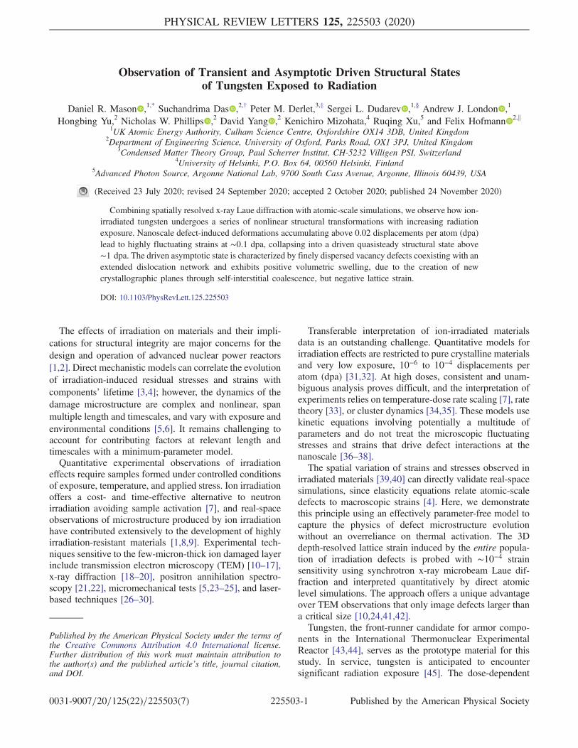
irradiated with self-ions to damage levels from 0.001 to10 dpa. The details of the sample preparation, ion-implantation method, and fluences used are provided inthe Supplemental Material [48], with references toRefs. [38,49–51]. Target displacements and ion rangesestimated using the SRIM code [50,51] show a ∼2.5 μmthick implanted layer [Fig. 1(a)].Three h001i grains (∼300 μm size) were identified in
each implanted sample using electron backscatteringdiffraction. In each grain, the strain in the h001i directionwas measured using depth-resolved Laue diffractionwith ∼10−4 strain sensitivity [18,20,52]. A polychromaticx-ray beam (7–30 keV) was focused to ∼300 nm FWHMusing Kirkpatrick-Baez mirrors, and the sample placed atthe beam focus in 45° reflection geometry. Diffractionpatterns were recorded on an area detector ∼500 mm abovethe sample. A resolution of ∼500 nm along the incidentbeam direction was achieved using the differential aperturex-ray microscopy technique [18,53–55].A 3D reciprocal space map of each (00n) reflection
was measured by monochromating the incident beam(ΔE=E ∼ 10−4) and scanning the photon energy [18,56].More information about the diffraction measurements isprovided in the Supplemental Material [48]. Figure 1(b)shows the diffracted intensity, integrated over the tangentialreciprocal space directions, plotted as a function of thescattering vector magnitude jqj and depth in the sample.The broad peak between 0 and ∼2.5 μm corresponds to theimplanted layer, whereas the sharp peak at ≫ 2.5 μmcorresponds to undamaged material. The measuredimplanted layer thickness is in good agreement with theSRIM prediction.Using the Laue data, we determine the lattice strain
component normal to the sample surface. The peak centerqfitðdÞ is found as a function of the depth using the center-of-mass method. In the small strain approximation, the latticestrain is then ϵzzðdÞ ¼ q0=qfitðdÞ − 1, where q0 is the peakposition for the reflection in an unstrained crystal found herefor each measurement using the average peak position in thelast 1.5 μm depth [e.g., d > 11 μm in Fig. 1(b)].To plot strain as a function of the dose, we average the
depth-dependent strain over the 2.5 μm implanted layer
[Fig. 1(c)]. Strain in the 0.001 dpa sample is very small. Atlow fluence, between 0.01 and 0.032 dpa, lattice expansionis observed. A transition occurs between 0.056 and0.32 dpa, where the implantation-induced strains nearlyvanish. At higher fluence (> 1 dpa), we observe an
FIG. 1. (a) Injected tungsten ion concentration and displace-ment damage calculated using SRIM for the 1 dpa sample. Theblue solid line shows the nominal dpa predicted using a thresholddisplacement energy of 68 eV. The shaded region shows upperand lower dpa bounds corresponding to threshold displacementenergies of 55 and 90 eV, respectively. (b) Diffracted x-rayintensity integrated in the tangential reciprocal space directionsfor the (008) Bragg peak of the 1 dpa tungsten sample. Intensity isshown as a function of the scattering vector magnitude jqj andsample depth. The superimposed red dotted line shows the fittedpeak centers qfitðdÞ. (c) Depth-averaged strain measured in ionimplantation experiments. Horizontal error bars indicate the dpauncertainty associated with the variation of assumed thresholddisplacement energies.
PHYSICAL REVIEW LETTERS 125, 225503 (2020)
225503-2

apparent lattice contraction manifested as negative latticestrain. This suggests a highly unusual dose-dependentchange in the defect microstructure over the exposureinterval spanned by the observations. We note that thedpa uncertainty associated with the choice of thresholddisplacement energy in SRIM calculations is small com-pared to the explored damage range [Fig. 1(c)].Simulations and interpretations.—To interpret experi-
mental observations at the fundamental level of defectmicrostructure, we performed Frenkel pair creation andrelaxation simulations [21,57,58] using the creationrelaxation algorithm (CRA) of Ref. [58]. Each step ofthe algorithm randomly selects a number of atoms andrandomly displaces them to new positions within thesimulation cell. The structure is relaxed using LAMMPS
[59] with an empirical potential for tungsten [60], underthree dimensional periodic boundary conditions with zerostress condition in the z direction (oriented with [001]) andzero strain in the x-y plane, reflecting the bulk constraintimposed by the substrate.This process is repeated many times and results in a
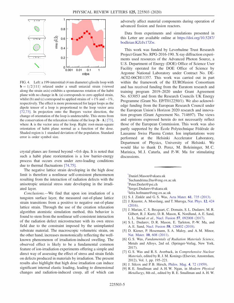
microstructure that begins with isolated vacancy and inter-stitial defects and evolves via interstitial dislocation loopnucleation and coalescence to an extended dislocation net-work. The ratio of Frenkel pairs inserted into total atomcontent is the canonical dpa dose (cdpa) [58]. Representativeresults in Fig. 2 show realizations of the microstructure at0.05 and 0.3 cdpa. At 0.05 cdpa, the developing internalstress field has driven some of the interstitials to nucleate into
dislocation loops, which by 0.3 cdpa have coalesced toextended dislocation structures, resulting in a microstructurethat is insensitive to further Frenkel pair insertion [58].Additional information about the atomistic simulations canbe found in the Supplemental Material [48], with referencesto Refs. [58,60,61].Frenkel pair insertion is a drastic simplification of the
20 MeV self-ion cascades used in experiment [63,64] butpredicts microstructures qualitatively similar to overlap-ping molecular dynamics cascade simulations [58,65]. Itshould be noted that there is no thermal activation in CRAsimulations—all relaxation is stress driven—so CRAdescribes microstructures where long-range diffusion doesnot occur. For the present case of high-purity, low-temperature tungsten, vacancy migration is inactive [66].The strong asymmetry in athermal mobility betweenvacancies and interstitials is therefore a justifiable physicallimit and central to the observed simulated structuralevolution. However, for materials that contain defectstructures (impurities, sessile dislocation structures, etc.)that hinder interstitial mobility [38,67] and reduce thisasymmetry, the situation is less clear but addressable usinga combination of dedicated experiments and CRA simu-lations as done here.As in experiment, a measure of lattice strain can be
obtained from a diffraction pattern, which for the case ofsimulation can be determined straightforwardly from theatomic positions of the microstructure produced by theFrenkel insertion method. Kinematic diffraction theorygives the diffraction spot intensity as being proportionalto the square of the structure factor IðqÞ ∝ jSðqÞj2, where
SðqÞ ¼ 1=ffiffiffiffiN
p X
j
exp ½iqzj�: ð1Þ
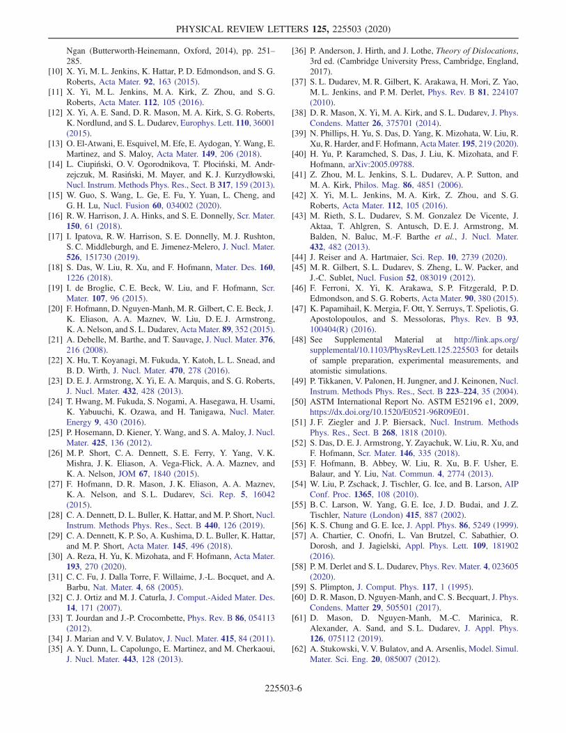
Here, both q and zj are along the out-of-plane z directionwith the latter being the z position of atom j. We use thesimulated [002] spot to find qfit and hence the lattice strainas above. The resulting lattice strain is plotted in Fig. 3(a) asa function of the cdpa and demonstrates similar behavior tothat seen in experiment, peaking at a cdpa of 0.05 afterwhich it becomes negative at higher values of cdpa. Whilethere is remarkably good quantitative agreement as afunction of the dose, the scale of the simulated latticestrain is an order of magnitude larger than in experiments.This difference may be attributed to the absence ofstructural relaxation arising from thermal fluctuations [3].Figure 3(a) also plots the volumetric strain associated
with the change in volume of the simulation cell defined asϵvol ¼ L=L0 − 1. Here, L is the evolving simulation cellperiodic length along the z direction. The volumetric straininitially follows the lattice strain, indicating that it arisesdirectly from a homogeneous lattice expansion, which inthis case is due to the low dose microstructural regime oflattice interstitials and vacancies. However, at doses of
FIG. 2. Representative Frenkel pair insertion simulations at0.05 (top) and 0.3 (bottom) dpa using the CRA algorithm. Thebox size is 20.2 × 20.2 × 63.2 nm3, and the unconstrained celldimension z is horizontal. Vacancy (blue) and interstitial (red)clusters with > 3 point defects are shown. Note the apparentformation of vacancy loops. A superimposed dislocation extrac-tion algorithm analysis [62] shows both 1=2h111i (green) andh100i (pink) dislocation lines. In the y ¼ 0 plane, the strain tensorcomponent ϵzz is shown, with color scale blue, white, redrepresenting −5%, 0, þ5% strain, respectively.
PHYSICAL REVIEW LETTERS 125, 225503 (2020)
225503-3

approximately 0.05 cdpa, the volumetric strain decouplesfrom the lattice strain and continues to increase with thedose. In this regime, interstitials cluster to form dislocationloops that grow in size and eventually coalesce, resulting inthe creation of new crystal planes along the z direction seenin Fig. 3(b). This process preserves the increase in volumedue to interstitial defects, while converting metastablemicrostructure into near-perfect crystal. This observationagrees with reports in other materials of lattice planecreation as a volumetric swelling mechanism [68,69].The good agreement between these simulations and experi-ment allows us to conclude that the change in the sign oflattice strain observed in experiment should not be inter-preted as a transition from irradiation-induced swelling toirradiation-induced contraction.Such a decoupling between volumetric and lattice strains
has been used to infer vacancy concentrations in metals [70]and has also been observed in simulations under bulkisotropic conditions [58]. The latter lead to a zero latticestrain at high doses, whereas in the present case symmetrybreaking leads to an asymptotic energy minimum with netnegative out-of-plane strain. The general high dose strain
condition as a function of the sample boundary conditions,elastic constants, and defect densities needs further analysis.Using the elastic dipole tensor formalism to represent
defects as sources of stress [71], and taking into accountthe zero x, y-strain condition imposed by the substrate andthe traction-free condition at the surface, we find thenonvanishing components of lattice strain and stressin the irradiated layer ϵzz ¼ ðΠzz=2μÞð1 − 2νÞ=ð1 − νÞand σxx ¼ σyy ¼ Πxx − νΠzz=ð1 − νÞ. Here, Πij is thevolume density of dipole tensors of defects ΠijðrÞ ¼P
a pðaÞij δðr −RaÞ, and μ and ν are the shear modulus
and the Poisson ratio of tungsten.Computing ϵzz and σxx from simulations, we find that the
lattice strain sign change coincides with the observation inthe simulated diffraction pattern of the start of the formationof additional atomic planes parallel to the surface; seeFig. 3(b). These planes, formed by the coalescence ofinterstitial dislocation loops, preserve the volumetric strainin the material, but, by converting the interstitial defectcontent into crystal planes, they reduce the lattice strain ofthe irradiated layer. This is confirmed by all components ofthe dipole density tensor becoming negative in the highdose limit.The simulated microstructure beyond 1 dpa is dominated
by network dislocations, a small number of dislocation loopsof both interstitial and vacancy type, and a large number ofexcess vacancies. The vacancy population totaling 2.5�0.1% lattice sites unoccupied leads to the observed netnegative lattice strain. The smaller magnitude lattice strainseen experimentally is likely due to thermally activateddefect recombination, an aspect not captured by the presentatomistic simulations.The anisotropy of the dipole tensor density emerging as a
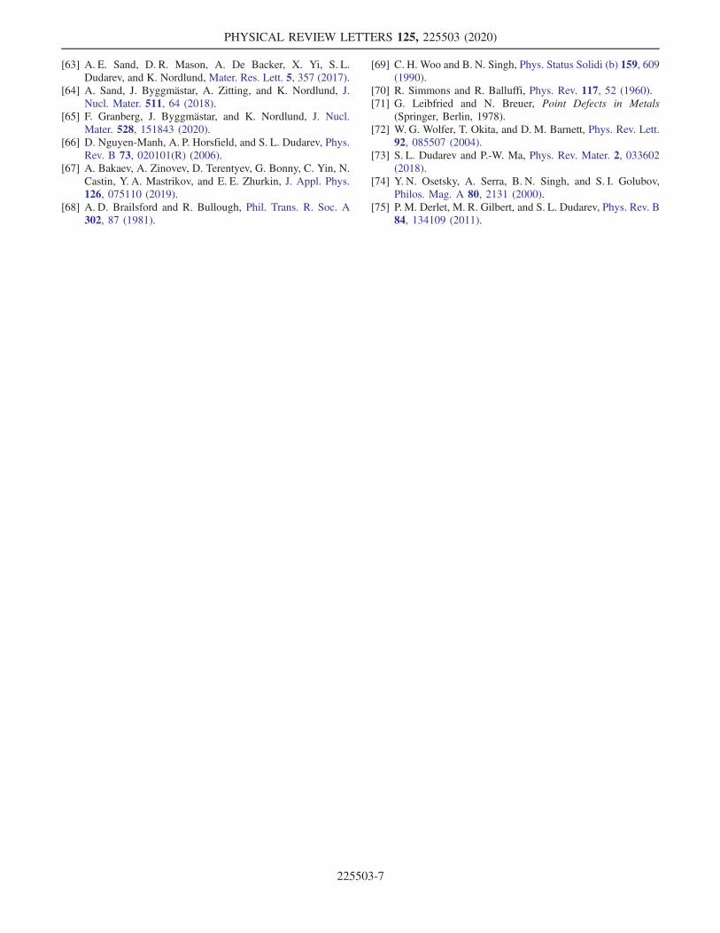
function of the dose is the result of the self-action of theuniaxial stress field developing in the irradiated layer on thepopulation of defects at a dose above∼0.1 dpa. Figures 4(a)–4(c) show how an isolated interstitial b ¼ 1=2h111i dis-location loop changes its habit plane in response to an applieduniaxial strain. The response stems from the minimization ofthe energy of interaction of each individual defect with strainE ¼ −pzzϵzz, where pzz is the zz component of the dipoletensor of a defect, for example, a dislocation loop [72,73].The average orientation of the habit plane n of the interstitialloops and extended dislocation structures in our simulationsismeasured and plotted via hn · zi as a function of the cdpa inthe right panel of Fig. 4. This is done through numericallydetermining the optimal habit plane orientation of thedislocation structures identified by the planes of interstitials.The figure reveals that at low dose this favors the orientationof the habit planes of interstitial loopswhose normals point inthe out-of-plane direction, favoring the coalescence of loopsinto new atomic planes. On the other hand, in the high doselimit, where ϵzz < 0, the habit plane normal vectors ofinterstitial loops reorient, tending now to point more towardthe in-plane direction. As a result, no additional atomic
-5
0
5
10
15
0.001 0.01 0.1 1.0 10
0.001 0.01 0.1 1.0 10(a)
stra
in ε
zz (
10-3
)
latt. strainvol. strainexpt (x10)
0
+2
+4
0.001 0.01 0.1 1.0 10
(b)
exce
sspl
anes
-0.02
-0.01
0
0.01
0.02
0.001 0.01 0.1 1.0 10
(c)
dipo
le te
nsor
den
sity
(eV
/A3 )
cdpa
ΠzzΠxx
FIG. 3. (a) Lattice strain and volumetric strain (dashed) derivedfrom simulations. Shaded region denotes 1 standard deviation.The experimental strain data are scaled by a factor of 10 tocompare trends as well as absolute values. Volumetric strain dueto the injected self-ions is small. (b) Number of excess planesrecorded in the simulation. (c) Defect dipole tensor density (seetext) computed from simulation cell stress. Note the horizontalscale is the same for all three plots.
PHYSICAL REVIEW LETTERS 125, 225503 (2020)
225503-4
crystal planes are formed beyond ∼0.6 dpa. It is noted thatsuch a habit plane reorientation is a low barrier-energyprocess that occurs even under zero-loading conditionsdue to thermal fluctuations [74,75].The negative lattice strain developing in the high dose
limit is therefore a nonlinear self-consistent phenomenonresulting from the interaction of radiation defects with theanisotropic uniaxial stress state developing in the irradi-ated layer.Conclusions.—We find that upon ion irradiation of a
tungsten surface layer, the measured out-of-plane latticestrain transitions from a positive to negative out-of-planelattice strain. Through the use of the creation relaxationalgorithm atomistic simulation method, this behavior isfound to stem from the nonlinear self-consistent interactionof the radiation defect microstructure with its own stressfield due to the constraint imposed by the unimplantedsubstrate material. The macroscopic volumetric strain, onthe other hand, increases monotonically reflecting the well-known phenomenon of irradiation-induced swelling. Theobserved effect is likely to be a fundamental commonfeature of ion-irradiation experiments offering a simple anddirect way of assessing the effect of stress and strain fieldson defects produced in materials by irradiation. The presentresults also highlight that high dose irradiation can inducesignificant internal elastic loading, leading to dimensionalchanges and radiation-induced creep, all of which can
adversely affect material components during operation ofadvanced fission and fusion reactors.
Data from experiments and simulations presented inthis Letter are available online at https://doi.org/10.5287/bodleian:KZrJx17Zw.
This work was funded by Leverhulme Trust ResearchProject Grant No. RPG-2016-190. X-ray diffraction experi-ments used resources of the Advanced Photon Source, aU.S. Department of Energy (DOE) Office of Science UserFacility operated for the DOE Office of Science byArgonne National Laboratory under Contract No. DE-AC02-06CH11357. This work was carried out in partwithin the framework of the EUROfusion Consortiumand has received funding from the Euratom research andtraining program 2019–2020 under Grant AgreementNo. 633053 and from the Research Councils UK EnergyProgramme (Grant No. EP/T012250/1). We also acknowl-edge funding from the European Research Council underthe European Union’s Horizon 2020 research and innova-tion program (Grant Agreement No. 714697). The viewsand opinions expressed herein do not necessarily reflectthose of the European Commission. This work was alsopartly supported by the École Polytechnique Federale deLausanne Swiss Plasma Center. Ion implantations wereperformed at the Helsinki Accelerator Laboratory,Department of Physics, University of Helsinki. Wewould like to thank D. Perez, M. Boleininger, M. C.Marinica, M. J. Caturla, and P.-W. Ma for stimulatingdiscussions.
*[email protected]†[email protected]‡[email protected]§[email protected]∥[email protected]
[1] S. J. Zinkle and G. S. Was, Acta Mater. 61, 735 (2013).[2] J. Knaster, A. Moeslang, and T. Muroga, Nat. Phys. 12, 424
(2016).[3] J. Marian, C. S. Becquart, C. Domain, S. L. Dudarev, M. R.
Gilbert, R. J. Kurtz, D. R. Mason, K. Nordlund, A. E. Sand,L. L. Snead et al., Nucl. Fusion 57, 092008 (2017).
[4] S. L. Dudarev, D. R. Mason, E. Tarleton, P.-W. Ma, andA. E. Sand, Nucl. Fusion 58, 126002 (2018).
[5] D. Kiener, P. Hosemann, S. A. Maloy, and A. M. Minor,Nat. Mater. 10, 608 (2011).
[6] G. S. Was, Fundamentals of Radiation Materials Science,Metals and Alloys, 2nd ed. (Springer-Verlag, New York,2017).
[7] G. S. Was and R. S. Averback, in Comprehensive NuclearMaterials, edited by R. J. M. Konings (Elsevier, Amsterdam,2012), Vol. 1, pp. 195–221.
[8] J. Silcox and P. B. Hirsch, Philos. Mag. 4, 72 (1959).[9] R. E. Smallman and A. H.W. Ngan, in Modern Physical
Metallurgy, 8th ed., edited by R. E. Smallman and A. H.W.
0
0.2
0.4
0.6
0.8
1
0.001 0.01 0.1 1
rms
(n.z
)
cdpa
^ ^
FIG. 4. Left: a 199-interstitial (4 nm diameter) glissile loop withb ¼ 1=2h111i relaxed under a small uniaxial strain (viewedalong the strain axis) exhibits a spontaneous rotation of the habitplane with no change in b. (a) corresponds to zero applied strain,whilst (b) and (c) correspond to applied strains ofþ1% and −1%,respectively. The effect is more pronounced for larger loops as thedipole tensor of a loop is proportional to the loop vector area[72,73]. In projection onto the Burgers vector direction, thechange of orientation of the loop is undetectable. This stems fromthe conservation of the relaxation volume of the loop ðb ·AÞ [73],where A is the vector area of the loop. Right: root-mean-squareorientation of habit plane normal as a function of the dose.Shaded region is 1 standard deviation of the population. Standarderror is order symbol size.
PHYSICAL REVIEW LETTERS 125, 225503 (2020)
225503-5
Ngan (Butterworth-Heinemann, Oxford, 2014), pp. 251–285.
[10] X. Yi, M. L. Jenkins, K. Hattar, P. D. Edmondson, and S. G.Roberts, Acta Mater. 92, 163 (2015).
[11] X. Yi, M. L. Jenkins, M. A. Kirk, Z. Zhou, and S. G.Roberts, Acta Mater. 112, 105 (2016).
[12] X. Yi, A. E. Sand, D. R. Mason, M. A. Kirk, S. G. Roberts,K. Nordlund, and S. L. Dudarev, Europhys. Lett. 110, 36001(2015).
[13] O. El-Atwani, E. Esquivel, M. Efe, E. Aydogan, Y. Wang, E.Martinez, and S. Maloy, Acta Mater. 149, 206 (2018).
[14] L. Ciupiński, O. V. Ogorodnikova, T. Płociński, M. Andr-zejczuk, M. Rasiński, M. Mayer, and K. J. Kurzydłowski,Nucl. Instrum. Methods Phys. Res., Sect. B 317, 159 (2013).
[15] W. Guo, S. Wang, L. Ge, E. Fu, Y. Yuan, L. Cheng, andG. H. Lu, Nucl. Fusion 60, 034002 (2020).
[16] R. W. Harrison, J. A. Hinks, and S. E. Donnelly, Scr. Mater.150, 61 (2018).
[17] I. Ipatova, R. W. Harrison, S. E. Donnelly, M. J. Rushton,S. C. Middleburgh, and E. Jimenez-Melero, J. Nucl. Mater.526, 151730 (2019).
[18] S. Das, W. Liu, R. Xu, and F. Hofmann, Mater. Des. 160,1226 (2018).
[19] I. de Broglie, C. E. Beck, W. Liu, and F. Hofmann, Scr.Mater. 107, 96 (2015).
[20] F. Hofmann, D. Nguyen-Manh, M. R. Gilbert, C. E. Beck, J.K. Eliason, A. A. Maznev, W. Liu, D. E. J. Armstrong,K. A. Nelson, and S. L. Dudarev, Acta Mater. 89, 352 (2015).
[21] A. Debelle, M. Barthe, and T. Sauvage, J. Nucl. Mater. 376,216 (2008).
[22] X. Hu, T. Koyanagi, M. Fukuda, Y. Katoh, L. L. Snead, andB. D. Wirth, J. Nucl. Mater. 470, 278 (2016).
[23] D. E. J. Armstrong, X. Yi, E. A. Marquis, and S. G. Roberts,J. Nucl. Mater. 432, 428 (2013).
[24] T. Hwang, M. Fukuda, S. Nogami, A. Hasegawa, H. Usami,K. Yabuuchi, K. Ozawa, and H. Tanigawa, Nucl. Mater.Energy 9, 430 (2016).
[25] P. Hosemann, D. Kiener, Y. Wang, and S. A. Maloy, J. Nucl.Mater. 425, 136 (2012).
[26] M. P. Short, C. A. Dennett, S. E. Ferry, Y. Yang, V. K.Mishra, J. K. Eliason, A. Vega-Flick, A. A. Maznev, andK. A. Nelson, JOM 67, 1840 (2015).
[27] F. Hofmann, D. R. Mason, J. K. Eliason, A. A. Maznev,K. A. Nelson, and S. L. Dudarev, Sci. Rep. 5, 16042(2015).
[28] C. A. Dennett, D. L. Buller, K. Hattar, and M. P. Short, Nucl.Instrum. Methods Phys. Res., Sect. B 440, 126 (2019).
[29] C. A. Dennett, K. P. So, A. Kushima, D. L. Buller, K. Hattar,and M. P. Short, Acta Mater. 145, 496 (2018).
[30] A. Reza, H. Yu, K. Mizohata, and F. Hofmann, Acta Mater.193, 270 (2020).
[31] C. C. Fu, J. Dalla Torre, F. Willaime, J.-L. Bocquet, and A.Barbu, Nat. Mater. 4, 68 (2005).
[32] C. J. Ortiz and M. J. Caturla, J. Comput.-Aided Mater. Des.14, 171 (2007).
[33] T. Jourdan and J.-P. Crocombette, Phys. Rev. B 86, 054113(2012).
[34] J. Marian and V. V. Bulatov, J. Nucl. Mater. 415, 84 (2011).[35] A. Y. Dunn, L. Capolungo, E. Martinez, and M. Cherkaoui,
J. Nucl. Mater. 443, 128 (2013).
[36] P. Anderson, J. Hirth, and J. Lothe, Theory of Dislocations,3rd ed. (Cambridge University Press, Cambridge, England,2017).
[37] S. L. Dudarev, M. R. Gilbert, K. Arakawa, H. Mori, Z. Yao,M. L. Jenkins, and P. M. Derlet, Phys. Rev. B 81, 224107(2010).
[38] D. R. Mason, X. Yi, M. A. Kirk, and S. L. Dudarev, J. Phys.Condens. Matter 26, 375701 (2014).
[39] N. Phillips, H. Yu, S. Das, D. Yang, K. Mizohata, W. Liu, R.Xu, R. Harder, and F. Hofmann, ActaMater. 195, 219 (2020).
[40] H. Yu, P. Karamched, S. Das, J. Liu, K. Mizohata, and F.Hofmann, arXiv:2005.09788.
[41] Z. Zhou, M. L. Jenkins, S. L. Dudarev, A. P. Sutton, andM. A. Kirk, Philos. Mag. 86, 4851 (2006).
[42] X. Yi, M. L. Jenkins, M. A. Kirk, Z. Zhou, and S. G.Roberts, Acta Mater. 112, 105 (2016).
[43] M. Rieth, S. L. Dudarev, S. M. Gonzalez De Vicente, J.Aktaa, T. Ahlgren, S. Antusch, D. E. J. Armstrong, M.Balden, N. Baluc, M.-F. Barthe et al., J. Nucl. Mater.432, 482 (2013).
[44] J. Reiser and A. Hartmaier, Sci. Rep. 10, 2739 (2020).[45] M. R. Gilbert, S. L. Dudarev, S. Zheng, L. W. Packer, and
J.-C. Sublet, Nucl. Fusion 52, 083019 (2012).[46] F. Ferroni, X. Yi, K. Arakawa, S. P. Fitzgerald, P. D.
Edmondson, and S. G. Roberts, Acta Mater. 90, 380 (2015).[47] K. Papamihail, K. Mergia, F. Ott, Y. Serruys, T. Speliotis, G.
Apostolopoulos, and S. Messoloras, Phys. Rev. B 93,100404(R) (2016).
[48] See Supplemental Material at http://link.aps.org/supplemental/10.1103/PhysRevLett.125.225503 for detailsof sample preparation, experimental measurements, andatomistic simulations.
[49] P. Tikkanen, V. Palonen, H. Jungner, and J. Keinonen, Nucl.Instrum. Methods Phys. Res., Sect. B 223–224, 35 (2004).
[50] ASTM International Report No. ASTM E52196 e1, 2009,https://dx.doi.org/10.1520/E0521-96R09E01.
[51] J. F. Ziegler and J. P. Biersack, Nucl. Instrum. MethodsPhys. Res., Sect. B 268, 1818 (2010).
[52] S. Das, D. E. J. Armstrong, Y. Zayachuk, W. Liu, R. Xu, andF. Hofmann, Scr. Mater. 146, 335 (2018).
[53] F. Hofmann, B. Abbey, W. Liu, R. Xu, B. F. Usher, E.Balaur, and Y. Liu, Nat. Commun. 4, 2774 (2013).
[54] W. Liu, P. Zschack, J. Tischler, G. Ice, and B. Larson, AIPConf. Proc. 1365, 108 (2010).
[55] B. C. Larson, W. Yang, G. E. Ice, J. D. Budai, and J. Z.Tischler, Nature (London) 415, 887 (2002).
[56] K. S. Chung and G. E. Ice, J. Appl. Phys. 86, 5249 (1999).[57] A. Chartier, C. Onofri, L. Van Brutzel, C. Sabathier, O.
Dorosh, and J. Jagielski, Appl. Phys. Lett. 109, 181902(2016).
[58] P. M. Derlet and S. L. Dudarev, Phys. Rev. Mater. 4, 023605(2020).
[59] S. Plimpton, J. Comput. Phys. 117, 1 (1995).[60] D. R. Mason, D. Nguyen-Manh, and C. S. Becquart, J. Phys.
Condens. Matter 29, 505501 (2017).[61] D. Mason, D. Nguyen-Manh, M.-C. Marinica, R.
Alexander, A. Sand, and S. L. Dudarev, J. Appl. Phys.126, 075112 (2019).
[62] A. Stukowski, V. V. Bulatov, and A. Arsenlis, Model. Simul.Mater. Sci. Eng. 20, 085007 (2012).
PHYSICAL REVIEW LETTERS 125, 225503 (2020)
225503-6
[63] A. E. Sand, D. R. Mason, A. De Backer, X. Yi, S. L.Dudarev, and K. Nordlund, Mater. Res. Lett. 5, 357 (2017).
[64] A. Sand, J. Byggmästar, A. Zitting, and K. Nordlund, J.Nucl. Mater. 511, 64 (2018).
[65] F. Granberg, J. Byggmästar, and K. Nordlund, J. Nucl.Mater. 528, 151843 (2020).
[66] D. Nguyen-Manh, A. P. Horsfield, and S. L. Dudarev, Phys.Rev. B 73, 020101(R) (2006).
[67] A. Bakaev, A. Zinovev, D. Terentyev, G. Bonny, C. Yin, N.Castin, Y. A. Mastrikov, and E. E. Zhurkin, J. Appl. Phys.126, 075110 (2019).
[68] A. D. Brailsford and R. Bullough, Phil. Trans. R. Soc. A302, 87 (1981).
[69] C. H. Woo and B. N. Singh, Phys. Status Solidi (b) 159, 609(1990).
[70] R. Simmons and R. Balluffi, Phys. Rev. 117, 52 (1960).[71] G. Leibfried and N. Breuer, Point Defects in Metals
(Springer, Berlin, 1978).[72] W. G. Wolfer, T. Okita, and D. M. Barnett, Phys. Rev. Lett.
92, 085507 (2004).[73] S. L. Dudarev and P.-W. Ma, Phys. Rev. Mater. 2, 033602
(2018).[74] Y. N. Osetsky, A. Serra, B. N. Singh, and S. I. Golubov,
Philos. Mag. A 80, 2131 (2000).[75] P. M. Derlet, M. R. Gilbert, and S. L. Dudarev, Phys. Rev. B
84, 134109 (2011).
PHYSICAL REVIEW LETTERS 125, 225503 (2020)
225503-7