physical property measurement systemtyson/ppms_documents/ppms_manual/1084-10… · physical...
TRANSCRIPT

Physical Property Measurement System
AC Measurement System (ACMS) Option User’s Manual
Part Number 1084-100 C-1

Quantum Design 11578 Sorrento Valley Rd. San Diego, CA 92121-1311 USA Technical support (858) 481-4400 (800) 289-6996 Fax (858) 481-7410 Fourth edition of manual completed June 2003.
Trademarks All product and company names appearing in this manual are trademarks or registered trademarks of their respective holders.
U.S. Patents 4,791,788 Method for Obtaining Improved Temperature Regulation When Using Liquid Helium Cooling 4,848,093 Apparatus and Method for Regulating Temperature in a Cryogenic Test Chamber 5,311,125 Magnetic Property Characterization System Employing a Single Sensing Coil Arrangement to Measure AC
Susceptibility and DC Moment of a Sample (patent licensed from Lakeshore) 5,647,228 Apparatus and Method for Regulating Temperature in Cryogenic Test Chamber 5,798,641 Torque Magnetometer Utilizing Integrated Piezoresistive Levers
Foreign Patents U.K. 9713380.5 Apparatus and Method for Regulating Temperature in Cryogenic Test Chamber
Quantum Design PPMS ACMS User’s Manual i
C O N T E N T S
Table of Contents PREFACE Contents and Conventions ...............................................................................................................................vii
P.1 Introduction .......................................................................................................................................................vii P.2 Scope of the Manual..........................................................................................................................................vii P.3 Contents of the Manual .....................................................................................................................................vii P.4 Conventions in the Manual...............................................................................................................................viii
CHAPTER 1 Introduction .......................................................................................................................................................1-1
1.1 Introduction ....................................................................................................................................................1-1 1.2 Theory of Operation .......................................................................................................................................1-1
1.2.1 Probe Magnetics ......................................................................................................................................1-2 1.2.2 Probe Thermometry.................................................................................................................................1-4 1.2.3 ACMS Electronics...................................................................................................................................1-4
1.3 System Safety .................................................................................................................................................1-5 1.3.1 Magnet Safety..........................................................................................................................................1-5 1.3.2 Cryogenic Safety .....................................................................................................................................1-5 1.3.3 Electric Safety..........................................................................................................................................1-6
CHAPTER 2 Hardware Installation....................................................................................................................................2-1
2.1 Introduction ....................................................................................................................................................2-1 2.2 Installing the Hardware ..................................................................................................................................2-1
2.2.1 Prepare for Installation ............................................................................................................................2-2 2.2.2 Install the ACMS Insert ...........................................................................................................................2-2 2.2.3 Install the ACMS Sample Transport........................................................................................................2-3 2.2.4 Connect the System .................................................................................................................................2-4 2.2.5 Activate the Option..................................................................................................................................2-4
2.3 Removing the Hardware.................................................................................................................................2-5 2.3.1 Prepare for Removal................................................................................................................................2-5 2.3.2 Remove the ACMS Sample Transport ....................................................................................................2-5 2.3.3 Remove the ACMS Insert........................................................................................................................2-5
CHAPTER 3 Sample Installation .........................................................................................................................................3-1
3.1 Introduction ....................................................................................................................................................3-1 3.2 Mounting the Sample......................................................................................................................................3-1
3.2.1 Method 1: Mounting a Sample on the ACMS Sample Holder ................................................................3-2 3.2.2 Method 2: Mounting a Sample on a Drinking Straw...............................................................................3-3
3.3 Installing the Sample ......................................................................................................................................3-4 3.4 Removing the Sample.....................................................................................................................................3-5

Contents Table of Contents
ii PPMS ACMS User’s Manual Quantum Design
CHAPTER 4 Measurements ...................................................................................................................................................4-1
4.1 Introduction ....................................................................................................................................................4-1 4.2 Overview of ACMS Measurements................................................................................................................4-1
4.2.1 AC Susceptibility Measurement Process.................................................................................................4-2 4.2.2 DC Magnetization Measurement Process................................................................................................4-3 4.2.3 Choosing a Measurement Method ...........................................................................................................4-3 4.2.4 Operating Modes .....................................................................................................................................4-4
4.3 Centering the Sample......................................................................................................................................4-5 4.3.1 Sample Centering Process .......................................................................................................................4-6 4.3.2 Centering the Sample with the AC Excitation Method ...........................................................................4-7
4.3.2.1 Centering the Sample in Immediate Mode .......................................................................................4-7 4.3.2.2 Centering the Sample in Sequence Mode .........................................................................................4-8
4.3.3 Centering the Sample with the DC Extraction Method ...........................................................................4-8 4.3.3.1 Centering the Sample in Immediate Mode .......................................................................................4-8 4.3.3.2 Centering the Sample in Sequence Mode .........................................................................................4-9
4.3.4 Specifying the Sample Location..............................................................................................................4-9 4.3.5 Moving the Sample................................................................................................................................4-10
4.4 Taking ACMS Measurements ......................................................................................................................4-11 4.4.1 Taking AC Susceptibility Measurements ..............................................................................................4-11
4.4.1.1 Taking a Measurement in Immediate Mode ...................................................................................4-11 4.4.1.2 Taking a Measurement in Sequence Mode.....................................................................................4-13
4.4.1.3 Limitation of the Applied AC Field Due to Eddy Current Heating...............................................4-16 4.4.2 Taking DC Magnetization Measurements .............................................................................................4-17
4.4.2.1 Taking a Measurement in Immediate Mode ...................................................................................4-17 4.4.2.2 Taking a Measurement in Sequence Mode.....................................................................................4-19
CHAPTER 5 Hardware ............................................................................................................................................................5-1
5.1 Introduction ....................................................................................................................................................5-1 5.2 Overview of Hardware ...................................................................................................................................5-1 5.3 ACMS Hardware ............................................................................................................................................5-2
5.3.1 ACMS Insert............................................................................................................................................5-2 5.3.1.1 Storage..............................................................................................................................................5-2
5.3.2 ACMS Sample Transport ........................................................................................................................5-3 5.3.2.1 Maintenance......................................................................................................................................5-3
5.3.3 ACMS Sample Holder Assembly............................................................................................................5-4 5.3.3.1 Maintenance......................................................................................................................................5-5
5.3.4 AC Board.................................................................................................................................................5-5 5.3.5 Servo Controller ......................................................................................................................................5-6 5.3.6 Sample Transport/Servo Controller Cable...............................................................................................5-6 5.3.7 Model 6000/Servo Controller Cable........................................................................................................5-7 5.3.8 Preamp Cable...........................................................................................................................................5-7
CHAPTER 6 Software...............................................................................................................................................................6-1
6.1 Introduction ....................................................................................................................................................6-1 6.2 Overview of the ACMS Software ..................................................................................................................6-1
6.2.1 ACMS Control Center .............................................................................................................................6-1 6.2.1.1 Datafile Tab ......................................................................................................................................6-2 6.2.1.2 Sample Tab .......................................................................................................................................6-3 6.2.1.3 Properties Tab...................................................................................................................................6-4

Contents Table of Contents
Quantum Design PPMS ACMS User’s Manual iii
6.2.1.4 Waveforms Tab ................................................................................................................................6-4 6.2.1.5 Advanced Tab...................................................................................................................................6-5 6.2.1.6 Configure Tab...................................................................................................................................6-6 6.2.1.7 Measurement Command Buttons......................................................................................................6-6
6.3 ACMS Status Log...........................................................................................................................................6-7 6.4 ACMS Data Files ...........................................................................................................................................6-7
6.4.1 Creating an ACMS Measurement Data File ............................................................................................6-8 6.4.2 Adding a Comment to an ACMS Measurement Data File ......................................................................6-9 6.4.3 Changing ACMS Data Files during a Sequence Run..............................................................................6-9
APPENDIX A Error and Warning Messages ................................................................................................................... A-1
A.1 Introduction ..................................................................................................................................................A-1 A.2 System Start-Up Error and Warning Messages ............................................................................................A-2 A.3 General Error and Warning Messages..........................................................................................................A-3 A.4 Centering Error and Warning Messages.......................................................................................................A-3 A.5 AC Measurement Error and Warning Messages ..........................................................................................A-4 A.6 DC Measurement Error and Warning Messages ..........................................................................................A-4 A.7 DSP I/O Error and Warning Messages.........................................................................................................A-5 A.8 Servo Controller Error and Warning Messages............................................................................................A-5
References..............................................................................................................................................References-1 Index ................................................................................................................................................................ Index-1

Contents Table of Figures
iv PPMS ACMS User’s Manual Quantum Design
Figures Figure 1-1. ACMS Insert and Coil Set ....................................................................................................................1-3 Figure 2-1. Installing the ACMS Insert ...................................................................................................................2-2 Figure 2-2. Installing the ACMS Sample Transport on a System without High Vacuum.......................................2-3 Figure 2-3. ACMS Connections ..............................................................................................................................2-4 Figure 3-1. ACMS Sample Holder Assembly .........................................................................................................3-2 Figure 3-2. Correctly Positioned Sample.................................................................................................................3-3 Figure 3-3. Installing the Sample ............................................................................................................................3-4 Figure 4-1. Locate Sample Dialog Box with AC Excitation Option Selected.........................................................4-6 Figure 4-2. Example of Plot of AC Centering in Waveforms Tab ..........................................................................4-7 Figure 4-3. Locate Sample Sequence Command Dialog Box with AC Excitation Option Selected.......................4-8 Figure 4-4. Example of Plot of DC Centering in Waveforms Tab ..........................................................................4-9 Figure 4-5. AC Magnetization Dialog Box. ..........................................................................................................4-11 Figure 4-6. Example Plot of AC Measurement in Waveforms Tab ......................................................................4-13 Figure 4-7. Measure Tab in AC Magnetization Sequence Command Dialog Box................................................4-14 Figure 4-8. Scan AC Field Dialog Box .................................................................................................................4-14 Figure 4-9. Scan Frequency Dialog Box ...............................................................................................................4-15 Figure 4-10. ACMS View Tree .............................................................................................................................4-15 Figure 4-11. PPMS Data Tab in AC Magnetization Sequence Command Dialog Box.........................................4-16 Figure 4-12. DC Magnetization Dialog Box. ........................................................................................................4-18 Figure 4-13. Example Plot of DC Measurement in Waveforms Tab ....................................................................4-18 Figure 4-14. Measure Tab in DC Magnetization Sequence Command Dialog Box..............................................4-19 Figure 5-1. ACMS Insert .........................................................................................................................................5-2 Figure 5-2. ACMS Sample Transport......................................................................................................................5-3 Figure 5-3. ACMS Sample Holder Assembly .........................................................................................................5-5 Figure 5-4. ACMS Servo Controller .......................................................................................................................5-6 Figure 5-5. Sample Transport/Servo Controller Cable............................................................................................5-7 Figure 5-6. Model 6000/Servo Controller Cable.....................................................................................................5-7 Figure 5-7. ACMS Preamp Cable............................................................................................................................5-7 Figure 6-1. Datafile Tab in ACMS Control Center .................................................................................................6-2 Figure 6-2. Sample Tab in ACMS Control Center ..................................................................................................6-3 Figure 6-3. Waveforms Tab in ACMS Control Center ...........................................................................................6-4 Figure 6-4. Advanced Tab in ACMS Control Center..............................................................................................6-5 Figure 6-5. Configure Tab in ACMS Control Center..............................................................................................6-6 Figure 6-6. ACMS Status Log.................................................................................................................................6-7 Figure 6-7. ACMS Datafile Comment Dialog Box .................................................................................................6-9 Figure 6-8. Datafile Tab in Change Datafile Dialog Box......................................................................................6-10

Contents Table of Tables
Quantum Design PPMS ACMS User’s Manual v
Tables Table 4-1. Measure Modes for AC Susceptibility Measurements.........................................................................4-12 Table 4-2. Amplitude Spacing Modes...................................................................................................................4-14 Table 4-3. Frequency Spacing Modes ...................................................................................................................4-15 Table 4-4. Maximum AC Field Amplitude (Oe) to Avoid Warming ..................................................................... 4-17 Table 5-1. ACMS Mounting Options ......................................................................................................................5-5

Quantum Design PPMS ACMS User’s Manual vii
P R E F A C E
Contents and Conventions
P.1 Introduction This preface contains the following information:
• Section P.2 discusses the overall scope of the manual.
• Section P.4 illustrates and describes conventions that appear in the manual.
• Section P.3 briefly summarizes the contents of the manual.
P.2 Scope of the Manual This manual discusses the operation of the AC Measurement System (ACMS) option hardware and software and explains how to take ACMS measurements.
For detailed information about the PPMS MultiVu application, which is the software running the Physical Property Measurement System (PPMS), refer to the Physical Property Measurement System: PPMS MultiVu Application User’s Manual. The ACMS software is integrated into PPMS MultiVu.
P.3 Contents of the Manual • Chapter 1 discusses the theory of
operation for the ACMS option. • Chapter 5 discusses the ACMS
hardware and maintenance issues. • Chapter 2 explains how to install and
remove the ACMS hardware. • Chapter 6 discusses the ACMS
software and ACMS data files. • Chapter 3 explains how to mount,
install, and remove samples. • Appendix A lists error and warning
messages. • Chapter 4 explains how to take
ACMS measurements.

Section P.4 Preface Conventions in the Manual Contents and Conventions
viii PPMS ACMS User’s Manual Quantum Design
P.4 Conventions in the Manual File menu Bold text distinguishes the names of menus, options, buttons, and panels appearing
on the PC monitor or on the Model 6000 PPMS Controller LCD screen.
File Open The symbol indicates that you select multiple, nested software options.
STATUS Bold text and all capital letters distinguish the names of keys located on the front panel of the Model 6000 PPMS Controller.
.dat The Courier font distinguishes characters you enter from the PC keyboard or from the Model 6000 PPMS Controller front panel. The Courier font also distinguishes code and the names of files and directories.
<Enter> Angle brackets distinguish the names of keys located on the PC keyboard.
<Alt+Enter> A plus sign connecting the names of two or more keys distinguishes keys you press simultaneously.
A pointing hand introduces a supplementary note.
An exclamation point inside an inverted triangle introduces a cautionary note.
A lightning bolt inside an inverted triangle introduces a warning.

Quantum Design PPMS ACMS User’s Manual 1-1
C H A P T E R 1
Introduction
1.1 Introduction This chapter contains the following information:
• Section 1.2 discusses the theory of operation for the ACMS option.
• Section 1.3 discusses how to safely operate the ACMS and PPMS systems.
1.2 Theory of Operation The Quantum Design AC Measurement System (ACMS) option for the Physical Property Measure-ment System (PPMS) is a versatile DC magnetometer and AC susceptometer. The state-of-the-art technology of the ACMS offers extensive susceptibility and magnetization capabilities while retaining a user-friendly environment. By being connected to the automated temperature and field control systems of the PPMS, the ACMS provides a highly powerful, fully automated magnetic workstation.
The ACMS insert houses the drive and detection coils, thermometer, and electrical connections for the ACMS system. The insert fits directly in the PPMS sample chamber and contains a sample space that lies within the uniform magnetic field region of the host PPMS, so DC field and temperature control can be performed with conventional PPMS methods. The sample is held within the insert’s coil set on the end of a thin, rigid sample rod. The sample holder is translated longitudinally by a DC servo motor located in the ACMS sample transport assembly. The DC servo motor provides rapid and very smooth longitudinal sample motion. The ACMS sample transport assembly mounts on top of the PPMS probe.

Section 1.2 Chapter 1 Theory of Operation Introduction
1-2 PPMS ACMS User’s Manual Quantum Design
1.2.1 Probe Magnetics The ACMS contains an AC-drive coil set that provides an alternating excitation field and a detection coil set that inductively responds to the combined sample moment and excitation field. The copper drive and detection coils are situated within the ACMS insert, concentric with the superconducting DC magnet of the PPMS. Refer to figure 1-1.
The drive coil is wound longitudinally around the detection coil set. The field amplitude that can be applied depends on the frequency of the alternating field and the temperature within the PPMS probe, but, at any temperature, the drive coil can generate alternating fields of up to ±10 Oe in a frequency range of 10 Hz to 10 kHz. As the frequency and temperature decrease, larger amplitude fields can be applied. At temperatures below 25 K, large amplitude fields can warm the PPMS sample chamber and ACMS insert. See section 4.4.1.3 for more information.
The detection coils are arranged in a first-order gradiometer configuration to help isolate the sample’s signal from uniform background sources. This configuration utilizes two sets of counterwound copper coils connected in series and separated by several centimeters. During DC measurements, a constant field is applied to the measurement region and the sample is moved quickly through both sets of coils, inducing a signal in them according to Faraday’s Law. This measurement method is commonly called the extraction method. During AC measurements, an alternating field is applied to the measurement region and the sample is positioned in the center of each detection coil. The detection coils indicate how the applied field is altered by the presence of the sample.
A compensation coil is situated outside the AC drive coil. The drive coil and compensation coil are counterwound and connected in series so that they receive the same excitation signal. A net field remains within the measurement region, but outside the measurement region the fields from the two coils tend to cancel. The compensation coil actually reduces dipole fields to quadropole fields. It effectively confines the excitation fields to the volume of the coil set, thereby reducing instrument interaction with conductive materials outside the measurement region⎯that is, the sample chamber walls, the magnet core, and so on⎯by three orders of magnitude. Each ACMS system is individually calibrated so that the drive coil and compensation coil produce the appropriate net excitation signal at the sample.
Each detection coil also contains a low-inductance calibration coil. These two single-turn calibration coils are connected in series and are situated at the center of each detection coil, where the sample measurements occur. During AC measurements, the accuracy of the phase and amplitude calibration is increased by placing the sample between the two detection coils and switching the calibration coils into the detection coil circuit with both possible polarities. The calibration coil is a feature found only on the Quantum Design ACMS.
CAUTION
Do not expose the ACMS coil set to temperatures greater than 350 K. The thermometers are calibrated only for temperatures below 350 K, and opera-tion above 350 K is excluded from the system warranty.
CAUTION
If the coil set is accidentally exposed to temperatures greater than 350 K, remove the ACMS insert from the PPMS only after the insert has thoroughly cooled. If the insert is removed while it is still hot, some of its components may break off.

Chapter 1 Section 1.2 Introduction Theory of Operation
Quantum Design PPMS ACMS User’s Manual 1-3
Figure 1-1. ACMS Insert and Coil Set
In addition to the alternating field supplied by the ACMS drive coil, the host PPMS platform can apply a constant field during both AC and DC measurements. The magnitude of the constant field can be up to 9 T, depending on the type of superconducting magnet in the PPMS. The PPMS superconducting magnets have a high field homogeneity (0.01%) within the measuring region.
During DC measurements, the amplitude of the detection coil signal is dependent upon both the extraction speed and the sample’s magnetic moment. The DC servo motor used by the ACMS extracts samples at speeds of approximately 100 cm/sec., thus increasing the signal strength over conventional DC extraction systems and reducing the contribution of time-dependent errors such as drift and 1/f noise. The short scan time also allows the averaging of several scans for each measurement, further reducing the contributions of random error. These advantages result in greater measurement accuracy and sensitivity compared to systems with slower sample extraction speeds.
One of the most notable features of the Quantum Design ACMS is its ability to accurately separate real and imaginary components of AC moment response. All AC instruments have phase shifts between the drive signal and the measured signal due to time constants in the electronics and coil set. These phase shifts are dependent upon parameters such as temperature, AC drive frequency, and magnetic field and thus change with various measurement parameters. It is important to be able to separate the sample phase shift from this instrumental phase shift. The ACMS corrects for instrument-dependent phase shift by actually measuring it in absence of the sample for each measurement point, using the calibration coil to simulate a sample with an entirely real response as described in section 4.2.

Section 1.2 Chapter 1 Theory of Operation Introduction
1-4 PPMS ACMS User’s Manual Quantum Design
1.2.2 Probe Thermometry The ACMS insert is thermally anchored to the base of the PPMS sample chamber. In this way the automated temperature control capabilities of the PPMS are used to control the temperature of the ACMS sample chamber.
In addition to the PPMS thermometers, the ACMS has a thermometer mounted directly on its coil form. This thermometer helps reduce errors from thermal time-constants that may exist at higher temperatures. The sample maintains close thermal contact with the ACMS thermometer by using the low-pressure helium vapor inside the PPMS sample chamber. This design gives fast thermal response times. The fast thermal response, precise temperature control hardware, and automation software provide accurate, time-efficient, user-friendly thermometry.
1.2.3 ACMS Electronics The ACMS coils are connected to the PPMS electronics through the 12-pin connector located at the base of the PPMS sample chamber. This configuration uses the existing electronic wiring that is built into the PPMS hardware, thus eliminating the need for additional wiring and connectors.
The ACMS option includes an AC board, which is installed in the Model 6000 PPMS Controller. The AC board provides the electronics that produce the desired excitation current in the drive coils, and it also effectively measures and separates the real and imaginary components of the sample’s magnetic response. The heart of the AC board is a digital signal processor (DSP) that synthesizes the excitation signal and processes the detection coils’ response signal.
The ACMS also includes a servo controller box. The servo controller box contains the electronics that control the ACMS sample transport servo motor.

Chapter 1 Section 1.3 Introduction System Safety
Quantum Design PPMS ACMS User’s Manual 1-5
1.3 System Safety The Physical Property Measurement System: Hardware Manual summarizes safety considerations for PPMS usage. These safety precautions also apply to the ACMS option. In general, use common sense around the PPMS and ACMS just as you would around any other laboratory equipment. Make certain that inexperienced PPMS users are supervised.
1.3.1 Magnet Safety Observe the following precautions for magnet safety. Also make certain you review the material in chapter 1 in the Physical Property Measurement System: Hardware Manual.
WARNING
Large magnetic fields are dangerous to anyone wearing a pacemaker or other electrical medical device. Make certain any person wearing a pacemaker or similar device stays at least 3.0−4.5 m (10−15 ft.) from the PPMS dewar whenever the PPMS superconducting magnet is charged.
WARNING
Large magnets, such as the PPMS superconducting magnets, can attract iron and other ferromagnetic materials with great force. Keep all iron, nickel, and other ferromagnetic objects at least 5.0 m (16.5 ft.) from the PPMS dewar.
The observable effects of magnetic fields are listed in chapter 1 in the Physical Property Measurement System: Hardware Manual.
1.3.2 Cryogenic Safety When you work with cryogenic materials such as liquid helium and liquid nitrogen, keep in mind that (1) they can expand when subjected to room temperature and (2) they can burn.
WARNING
The extreme cold of liquid and gaseous cryogens can cause serious burns. Always wear protective clothing, including thermal gloves, eye protection, and covered shoes, when you work with liquid helium, liquid nitrogen, or any other cryogen.
WARNING
In a poorly ventilated room, helium can displace air and lead to asphyxiation. Always perform cryogen transfers in a well-ventilated room. In the event of a rupture or spill, vent the room immediately and evacuate all personnel.

Section 1.3 Chapter 1 System Safety Introduction
1-6 PPMS ACMS User’s Manual Quantum Design
Cryogens stored in confined spaces are subject to extremely high pressure buildup, resulting in dangerous explosions. Pressure relief valves are installed on the PPMS dewar and cooling annulus, and rupture disks are installed on the vacuum sleeve and dewar to eliminate the possibility of explosion. Do not remove, disable, or otherwise tamper with these safety devices.
1.3.3 Electric Safety The PPMS and ACMS equipment is powered by standard 110-VAC or 220-VAC power sources. These voltages are potentially lethal. Exercise appropriate care when you open any of the PPMS electronic units.
• Unplug all electronic equipment before you remove any covers. • Keep electrical cords in good working condition, and replace frayed and damaged cords. • Keep liquids away from the workstation.

Quantum Design PPMS ACMS User’s Manual 2-1
C H A P T E R 2
Hardware Installation
2.1 Introduction This chapter contains the following information:
• Section 2.2 explains how to install the ACMS hardware in the PPMS.
• Section 2.3 explains how to remove the ACMS hardware from the PPMS.
2.2 Installing the Hardware PPMS systems shipped with the ACMS option have all controller hardware and software installed prior to shipment. The ACMS insert and ACMS sample transport are the only components requiring user installation and removal. The modular design of the ACMS option allows the ACMS insert and ACMS sample transport to be installed and removed as necessary. The instructions in this chapter explain how to install the insert and sample transport and how to activate the ACMS option.
NOTE
The instructions in this chapter assume that the basic PPMS is already set up⎯that is, the probe inserted in the dewar, the dewar filled with helium, and the Model 6000 PPMS Controller connected to the probe and personal computer. If this is not the case, set up the PPMS as described in the Physical Property Measurement System: Hardware Manual before continuing.
Temperature and chamber commands may be issued from either the Model 6000 PPMS Controller or the PPMS MultiVu software application. The instructions in this chapter illustrate use of PPMS MultiVu. For detailed information about PPMS MultiVu, refer to the Physical Property Measurement System: PPMS MultiVu Application User’s Manual.

Section 2.2 Chapter 2 Installing the Hardware Hardware Installation
2-2 PPMS ACMS User’s Manual Quantum Design
2.2.1 Prepare for Installation 1. Set the PPMS system temperature to 298 K. You can do this as follows: (a) Select Instrument
Temperature, (b) specify a set point of 298 K, (c) specify the rate of ramping to the set point, (d) select the temperature approach mode, and (e) select Set. Do not continue with installation until the temperature reaches 298 K.
2. Vent the PPMS sample chamber. You can do this as follows: (a) Select Instrument Chamber and (b) select the Vent Cont. button.
3. Remove the blank flange from the top of the PPMS probe. Removing the cover is impossible until the sample chamber is vented.
4. Remove any sample puck or PPMS option that is installed in the sample chamber. Refer to the Physical Property Measurement System: Hardware Manual to remove a sample puck. Refer to the appropriate PPMS option manual to remove an option.
2.2.2 Install the ACMS Insert 1. Attach the 4-40 thumbscrew to the top of the ACMS insert. 2. Carefully lower the ACMS insert, coil-set end first, into the PPMS sample chamber.
Figure 2-1. Installing the ACMS Insert
3. Correctly position the ACMS insert as follows: (a) Use the 4-40 thumbscrew to rotate the insert so that the white dot on the top of the insert faces the front of the PPMS probe⎯that is, the side with the Quantum Design logo; and then (b) when you feel the insert drop into place, indicating that the keyed interface at its base is properly aligned, press down on the insert until it snaps into place.
4. Remove the 4-40 thumbscrew from the ACMS insert.

Chapter 2 Section 2.2 Hardware Installation Installing the Hardware
Quantum Design PPMS ACMS User’s Manual 2-3
2.2.3 Install the ACMS Sample Transport 1. Hold the ACMS sample transport so that the electrical port on its rear panel is oriented correctly.
• If your PPMS does not include the High-Vacuum option, hold the ACMS sample transport so that the electrical port faces the rear of the PPMS probe head⎯that is, away from the Quantum Design logo. Refer to figure 2-2.
• If your PPMS does include the High-Vacuum option, hold the ACMS sample transport so that the electrical port faces the front of the PPMS probe head⎯that is, toward the Quantum Design logo.
2. Swing out the two legs on the bottom of the ACMS sample transport. If your PPMS includes the High-Vacuum option, angle the legs in order to avoid hitting the pop-off valves on top of the dewar.
3. Inspect the O-ring on the bottom of the ACMS sample transport. Clean the O-ring if necessary. 4. Set the ACMS sample transport on top of the flange opening. 5. Clamp the two transport legs shut. Verify that the legs snap into place so that they engage
pressure with the O-ring. 6. Verify that the O-ring mating with the probe flange is properly seated in the probe flange. 7. Verify that the small, black cap is correctly positioned on top of the sample transport.
Figure 2-2. Installing the ACMS Sample Transport on a System without High Vacuum
Section 2.2 Chapter 2 Installing the Hardware Hardware Installation
2-4 PPMS ACMS User’s Manual Quantum Design
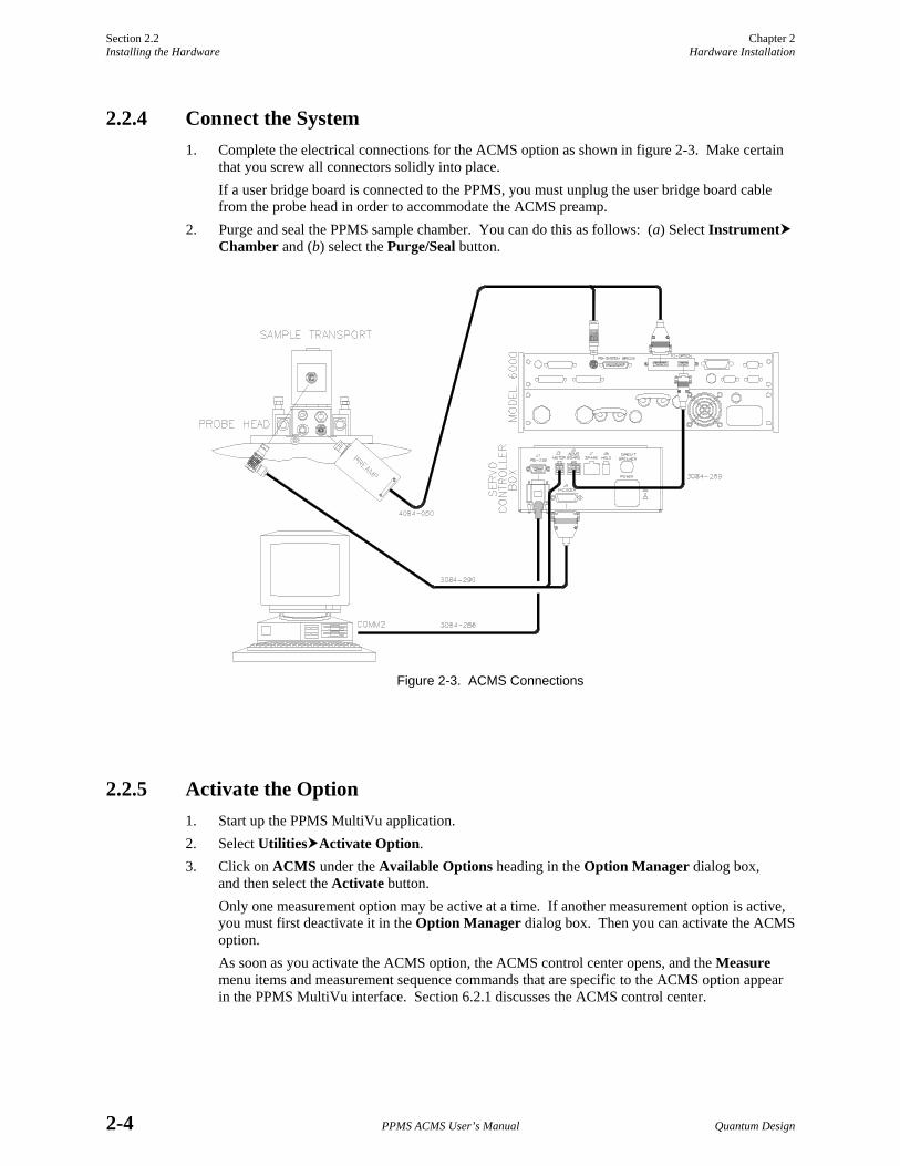
2.2.4 Connect the System 1. Complete the electrical connections for the ACMS option as shown in figure 2-3. Make certain
that you screw all connectors solidly into place. If a user bridge board is connected to the PPMS, you must unplug the user bridge board cable from the probe head in order to accommodate the ACMS preamp.
2. Purge and seal the PPMS sample chamber. You can do this as follows: (a) Select Instrument Chamber and (b) select the Purge/Seal button.
Figure 2-3. ACMS Connections
2.2.5 Activate the Option 1. Start up the PPMS MultiVu application. 2. Select Utilities Activate Option. 3. Click on ACMS under the Available Options heading in the Option Manager dialog box,
and then select the Activate button. Only one measurement option may be active at a time. If another measurement option is active, you must first deactivate it in the Option Manager dialog box. Then you can activate the ACMS option. As soon as you activate the ACMS option, the ACMS control center opens, and the Measure menu items and measurement sequence commands that are specific to the ACMS option appear in the PPMS MultiVu interface. Section 6.2.1 discusses the ACMS control center.

Chapter 2 Section 2.3 Hardware Installation Removing the Hardware
Quantum Design PPMS ACMS User’s Manual 2-5
2.3 Removing the Hardware The ACMS insert and ACMS sample transport should be removed from the PPMS when the system will not be used. The procedure for removing the insert and sample transport is essentially the reverse of the installation procedure.
When the ACMS insert is not in place inside the sample chamber, it should be stored in such a way that it is either hanging from the top end-support or resting horizontally with support along its length.
2.3.1 Prepare for Removal 1. Set the PPMS system temperature to 298 K. You can do this as follows: (a) Select Instrument
Temperature, (b) specify a set point of 298 K, (c) specify the rate of ramping to the set point, (d) select the temperature approach mode, and (e) select Set. Do not continue with the removal procedure until the temperature reaches 298 K.
2. Vent the PPMS sample chamber. You can do this as follows: (a) Select Instrument Chamber and (b) select the Vent Cont. button.
3. Remove the sample and sample holder from the ACMS insert. Refer to section 3.4.
2.3.2 Remove the ACMS Sample Transport 1. Disconnect the sample transport/servo cable from the ACMS sample transport. The cable may
remain connected to the servo controller box. Refer to figure 2-3. When you disconnect the sample transport/servo cable, the sample chamber will vent.
2. Remove the ACMS sample transport from the PPMS probe.
2.3.3 Remove the ACMS Insert 1. Attach the 4-40 thumbscrew to the top of the ACMS insert. 2. Use the thumbscrew to carefully lift the insert out of the probe. Set the insert in a safe place
according to the system care instructions in section 5.3.1.1. 3. Return the blank flange to the top of the probe head, or install another PPMS option. 4. Unplug the preamp from the PPMS probe head. Refer to figure 2-3. 5. Do one of the following: Either (a) verify that the blank flange is properly positioned and the
clamp is installed or (b) verify that the sample chamber is sealed. 6. Purge and seal the PPMS sample chamber. You can do this as follows: (a) Select Instrument
Chamber and (b) select the Purge/Seal button.

Quantum Design PPMS ACMS User’s Manual 3-1
C H A P T E R 3
Sample Installation
3.1 Introduction This chapter contains the following information:
• Section 3.2 explains two popular methods for mounting samples for ACMS measurements.
• Section 3.4 explains how to remove a sample from the ACMS insert.
• Section 3.3 explains how to insert a sample into the ACMS insert.
3.2 Mounting the Sample Samples for ACMS measurements may be mounted directly on the ACMS sample holder or on a clear plastic drinking straw. Refer to sections 3.2.1 and 3.2.2, respectively. Clear plastic drinking straws are available from Quantum Design.
NOTE
The material out of which the ACMS sample rod is constructed has susceptibility < 2 × 10⁻⁷ and can be detected by the ACMS. A clear plastic drinking straw, on the other hand, adds a negligible magnetic moment that is below the instrument’s noise floor. However, unlike a drinking straw, the bucket on the ACMS sample holder can accom- modate powered samples.

Section 3.2 Chapter 3 Mounting the Sample Sample Installation
3-2 PPMS ACMS User’s Manual Quantum Design
3.2.1 Method 1: Mounting a Sample on the ACMS Sample Holder 1. Remove the short sample rod from the ACMS sample holder by gently rotating it relative to
the long sample rod.
Figure 3-1. ACMS Sample Holder Assembly
2. Remove the bucket by rotating it relative to the short sample rod. 3. Secure the sample inside the sample bucket.
NOTE
All samples undergo some motion during measurement. During DC measure-ments, samples are subject to rapid acceleration. Because the sample must not shift within the sample holder bucket, it may be necessary to secure the sample with a low-susceptibility material.
4. Reattach the bucket to the short sample rod. Screw the bucket into place to ensure a tight fit. 5. Reattach the short sample rod to the long sample rod. The sample is now ready to be installed
in the ACMS insert.
Additional sample holder rods are provided by Quantum Design, so samples may be marked and stored in the sample rod for repeated measurements.

Chapter 3 Section 3.2 Sample Installation Mounting the Sample
Quantum Design PPMS ACMS User’s Manual 3-3
3.2.2 Method 2: Mounting a Sample on a Drinking Straw 1. Cut off a small section of a clear plastic drinking straw. The section must be small enough to fit
lengthwise inside the straw. 2. Place the sample inside the small straw section, as in figure 3-2. Quantum Design recommends
that you use Teflon-coated tweezers for this step. Placing the sample in the correct orientation can be difficult, so this step may take some practice.
3. Insert the sample and small straw section inside the straw so that the openings of the small straw section are obstructed by the walls of the larger straw.
4. Verify that the sample is secure and will not vibrate or shift. The sample may be subjected to high-speed motion during the measurement.
5. Puncture three or four small holes in the upper portion of the straw (about 2.5 cm or 1 inch from the end) to allow air to escape during sample chamber evacuation.
Puncture Holes
Figure 3-2. Correctly Positioned Sample
6. Remove the short sample rod from the ACMS sample holder by gently rotating it relative to the long sample rod.
7. Position the sample so that it is about 41/8 inch (10.5 cm) from the bottom of the long sample rod. This ensures that the sample is positioned near the center of the detection coils.
8. Use a straw adapter to allow the straw to fit snugly over the threads. 9. Secure the straw to the long sample rod. 10. Cut off the excess straw below the sample. This portion of the straw is subject to contact with
the end of the ACMS insert which prohibits full sample motion during ACMS operation. 11. Place a small piece of tape over the bottom end of the straw. This is intended to prevent the
sample from falling into the chamber if it comes loose from the sample holder.
The sample is now ready to be installed in the ACMS insert.
You may find other means of mounting samples that will work better for your particular application.

Section 3.3 Chapter 3 Installing the Sample Sample Installation
3-4 PPMS ACMS User’s Manual Quantum Design
3.3 Installing the Sample
NOTE
The sample may be installed in the ACMS insert only if the ACMS hardware is installed and the ACMS option is activated in the PPMS MultiVu software. Refer to chapter 2 to install and activate the ACMS option.
1. Mount the sample on the ACMS sample holder or on a clear plastic drinking straw as described in section 3.2.1 or 3.2.2, respectively.
2. Set the system temperature to 298 K. Do not continue with the sample installation until the system reaches room temperature. Otherwise, ice may accumulate within the sample chamber and block sample motion.
3. Select the Sample tab in the ACMS control center (see figure 6-2). 4. Select the Change button in the Sample tab. The sample space is vented with helium. This
protects the system from contamination and ice accumulation and enables sample holder insertion.
5. Remove the small, black cap from the sample chamber access port on the ACMS sample transport. Place the cap on the cap holder for safe storage.
6. Lower the ACMS sample holder, sample end first, through the sample chamber access port on the top of the ACMS sample transport. Insert the sample holder completely into the sample chamber. As you lower the sample holder, it may be helpful to twist it in order to guide the baffles into place.
7. Snap the sample holder into place by lightly pressing down on its black end-cap.
8. Return the cover to the sample transport. 9. Select the Finished button in the Sample tab.
When you select Finished, the PPMS performs a purge sequence to remove air from the sample chamber. In addition, the ACMS sample transport moves through its full travel length to ensure that its path is unobstructed.
NOTE
You must select the Finished button before you run any measurements. If you try to run a measurement before you select Finished, the software displays an error message.
If sample insertion is not completed within 90 seconds, the servo motor is turned off to prevent it from overheating. To turn the servo motor back on and complete the sample insertion, you select the Motor On button in the Sample tab. Notice that you must still select Finished after you select Motor On.
If the sample offers a large resistance to the gas flow of the purge sequence, the strong suction forces are indistinguishable from an obstruction, and the software may erroneously report an obstruction. If an obstruction is detected, you are prompted to cancel the insertion or retry. If you elect to reinsert the sample, the sample space is vented to allow you to remove the cover and repeat the sample-loading process. Once the sample is reinserted, press the OK button to complete the installation process.
Figure 3-3. Installing the Sample

Chapter 3 Section 3.4 Sample Installation Removing the Sample
Quantum Design PPMS ACMS User’s Manual 3-5
3.4 Removing the Sample 1. Set the system temperature to 298 K. Do not continue with the sample removal until the system
reaches room temperature. Otherwise, ice may accumulate within the sample chamber and block sample motion.
2. Select the Sample tab in the ACMS control center (see figure 6-2). 3. Select the Change button in the Sample tab. The system immediately prepares for sample
removal by venting the sample chamber. 4. Remove the sample transport cover and place it on the smaller black cap for safe storage. Refer
to figure 3-3. 5. Grip the small black cap on the sample holder assembly and then remove the sample holder
assembly from the ACMS sample chamber. It may be helpful to twist the sample holder as you raise it to guide the baffles through the openings.
6. Return the cover to the sample transport. 7. Press the Finished button in the Sample tab.
If sample removal is not completed within 90 seconds, the servo motor is turned off to prevent it from overheating. To turn the servo motor back on and complete the sample removal, you select the Motor On button in the Sample tab. Notice that you must still select Finished after you select Motor On.

Quantum Design PPMS ACMS User’s Manual 4-1
C H A P T E R 4
Measurements
4.1 Introduction This chapter contains the following information:
• Section 4.2 describes the AC and DC measurement processes and compares these two measurement types.
• Section 4.4 explains how to perform AC and DC measurements.
• Section 4.3 describes the AC and DC centering methods and explains how to center the sample.
4.2 Overview of ACMS Measurements The ACMS is both a DC magnetometer and an AC susceptometer. The distinction between the two types of measurements is important. DC magnetization measurements measure a sample’s magnetic moment in an applied magnetic field at a specific temperature. AC susceptibility measurements do not directly measure a sample’s magnetic moment and are far more sensitive. Section 4.2.1 describes the AC susceptibility measurement process. Section 4.2.2 describes the DC magnetization measure-ment process. Section 4.2.3 discusses some factors to consider when you are deciding what type of measurement to take.
Once the ACMS is electronically connected to the Model 6000, it is fully configured to perform both AC susceptibility and DC magnetization measurements. No hardware or software reconfiguration is necessary to switch from AC susceptibility to DC magnetization. In fact, you can actually perform both measurements on a sample within a single sequence. To save time, both AC susceptibility and DC magnetization can be measured at each measurement step. If the magnetization criteria are differ-ent from the susceptibility criteria, the sequence can be configured to perform each measurement individually, yet within a single sequence.
NOTE
Before a sample is measured for the first time, it should be centered relative to the detection coils that are in the ACMS insert. Section 4.3 discusses centering methods.

Section 4.2 Chapter 4 Overview of ACMS Measurements Measurements
4-2 PPMS ACMS User’s Manual Quantum Design
4.2.1 AC Susceptibility Measurement Process AC susceptibility measurements do not directly measure a sample’s magnetic moment. Samples with very different magnetic moments can have the same response to a changing magnetic field if their susceptibilities are the same in the measurement regimes of interest. The AC susceptibility option in the ACMS adds a small alternating field to the large applied field from the PPMS superconducting magnet and measures a sample’s magnetic moment response. Both the amplitude and phase of this response are reported. Alternatively, the ACMS can report the in-phase and quadrature components of the sample’s response. Note that the reported amplitude is the amplitude of the change in magnetic moment dM and is not an absolute magnetic moment or a susceptibility. To obtain the AC suscepti-bility, you must divide the amplitude of the change in moment by the amplitude of the alternating field dH. This gives
χ ac = dM/dH.
Remember that this is only the local slope of the sample’s magnetization curve M(H) and not the “true” susceptibility
χ = M /H .
It is important to note the difference between AC susceptibility and “true” susceptibility when dealing with samples that have non-linear magnetization curves.
During an AC susceptibility measurement, an alternating magnetic field is applied to the measurement region by itself or in addition to the constant field applied by the PPMS superconducting magnet. This alternating field is synthesized by the AC board’s DSP and sent to a digital-to-analog converter. The analog signal is amplified in order to excite the drive and compensation coils.
By default, the sample undergoes a five-point measurement process that utilizes the calibration coil to increase measurement accuracy. The first reading is made with the sample positioned in the center of the bottom detection coil. Then the sample is positioned in the center of the top detection coil, and then in the center of the bottom coil again. During all three readings, the signals from the detection coil array are amplified, low-pass filtered, and digitized by an analog-to-digital converter (A/D). These signals are stored as waveform blocks in the data buffer. All 128 buffer points are used to record each response waveform. The points are fitted and compared to the driving signal to determine the real and imaginary components of the response when the sample is in the center of each detection coil. (Imaginary components are in phase with the driving signal and real components are 90° out of phase with the driving signal.) Subtracting one reading from the other gives a sample vector in the complex plane.
When the bottom-top-bottom coil readings are complete, the sample is placed at the center of the detection coil array so that it is between the two detection coils. Two more readings are taken with the calibration coil switched into the detection circuit with opposing polarities. The real and imaginary components of each response waveform are obtained by again fitting the data and comparing it to the driving signal. The two calibration readings are subtracted to yield a calibration vector in the complex plane. Subtracting the two calibration readings subtracts out the sample signal, leaving only environ-mental and instrumental factors that affect the reading. The calibration vector is used to accurately place the sample vector at the origin with the proper orientation and scaling. The true values of interest for the sample are then reported, either as moment amplitude and phase (magnitude and angle of the sample vector) or as in-phase and out-of-phase (or quadrature) components of the moment (real and imaginary components of the sample vector.) Notice that in-phase components of the response signal are in phase with the ideal response signal, which is 90° out of phase with the driving signal. This is due to the nature of Faraday’s law. During each measurement, several waveform blocks can be measured and averaged to reduce random noise that may be present in the signal.

Chapter 4 Section 4.2 Measurements Overview of ACMS Measurements
Quantum Design PPMS ACMS User’s Manual 4-3
4.2.2 DC Magnetization Measurement Process DC magnetization measurements measure a sample’s magnetic moment M in an applied magnetic field H at a specific temperature T (M = M(H,T)). The ACMS does not use Quantum Design SQUID tech-nology to perform DC magnetization measurements. Instead, it moves the sample through a set of copper coils and analyzes the induced signal with a digital signal processor (DSP) to determine the sample’s magnetic moment.
During a DC magnetization measurement, the PPMS applies a constant magnetic field to the sample space, and the sample transport servo motor translates the sample through the entire detection coil set in approximately 0.05 second. To synchronize sample translation with data acquisition, the servo motor sends a handshake signal to the DSP that triggers data acquisition. The ACMS takes 4096 voltage readings during sample translation and creates a voltage profile curve for the translation. The detection coils register a voltage proportional to the rate of change of magnetic flux through them, so the voltage profile is the time derivative of the net flux through the coils. The actual sample moment is obtained by numerically integrating the voltage profile and fitting the known waveform for a dipole moving through the detection coils to the resulting data using a regression algorithm. Alternatively, the integrated data can be used to calculate the sample’s center position.
4.2.3 Choosing a Measurement Method In the ACMS option, AC measurements are nearly three orders of magnitude more sensitive than DC measurements. Conductive samples usually yield much larger signals during AC measurements. However, in some situations, DC measurements produce better results than AC measurements. For example, weakly paramagnetic samples with magnetic moments near the noise floor of the ACMS’s AC measurement capability (~1 × 10⁻⁸ emu) can often be detected more easily in the large DC fields applied by the PPMS superconducting magnet, because the larger DC field raises the sample’s moment well above the noise floor for DC measurements (~2.5 × 10⁻⁵ emu). In such cases a DC center (section 4.3.3) is appropriate. Most PPMS platforms contain at least 7-T DC magnets, while the ACMS can only apply alternating fields of up to ±10 Oe consistently (1 T = 10,000 Oe). In addition, large or asymmetric sample holders generally require DC methods to properly account for background sources. Other symmetry and field uniformity concerns⎯such as small applied fields⎯usually demand DC methods as well.
There are many other points to consider when determining whether to use AC or DC centering and measurement methods. It is your responsibility to choose centering and measurement techniques that are appropriate for the type of information being sought and the type of sample being examined. Important sample characteristics to consider include type of magnetic behavior, magnetic moment, conductivity, shape, and size. Applied field and temperature can also be important. Finally, the nature of the information that the experiment examines should be considered. AC susceptibility measurements are fundamentally different than DC measurements in that they report a change in a sample’s magnetic moment with a relatively small change in field, rather than a sample’s absolute moment in a relatively large constant field. Contact a Quantum Design representative if you would like to discuss considerations specific to your application.
The ACMS also supports independent sample movement, because moving the sample independently of the measurement may be important for particular experiments. When the ACMS is not taking a measurement, you may move the sample to a specific location within the detection coils. Refer to section 4.3.5.

Section 4.2 Chapter 4 Overview of ACMS Measurements Measurements
4-4 PPMS ACMS User’s Manual Quantum Design
4.2.4 Operating Modes ACMS measurements and sample centering may run in immediate mode or sequence mode. ACMS control center commands and PPMS MultiVu Measure menu commands execute operations immedi-ately, but each control center or menu command must be selected manually. ACMS measurement sequence commands included in a PPMS MultiVu sequence file are executed automatically when they are read while the sequence runs. Any number and combination of measurement sequence commands may be included in a sequence file.
Data from immediate-mode measurements or sample centering is saved only if an ACMS measure- ment data file is selected to store the data, and once the measurement is complete, a Save command is issued, prompting the system to save the data to the specified file. Measurement and selected system data read during sequence mode measurements and sample centering is automatically saved to the specified data file.
The immediate-mode measurement dialog boxes show the results from the last measurement of that same type (see figure 4-5, for example). The sequence mode measurement dialog boxes do not show measurement results, but you can use them to select which system data items you want to save to the specified ACMS measurement data file (see figure 4-11).
Diagnostic plots, which appear in the Waveforms tab in the ACMS control center, are generated for all measurements and sample centering. To view the waveforms, you can also open ACMS raw measurement data files at any time.
NOTE
You are encouraged to use the ACMS control center to perform all normal system operations. The automated routines in the control center help ensure that you complete the necessary procedures when you install new samples and create data files. This chapter illustrates use of the control center.
The Physical Property Measurement System: PPMS MultiVu Application User’s Manual discusses sequence files, sequence operation, and all standard PPMS sequence commands in detail.

Chapter 4 Section 4.3 Measurements Centering the Sample
Quantum Design PPMS ACMS User’s Manual 4-5
4.3 Centering the Sample
NOTE
The sample can be centered only if the ACMS hardware is installed and the ACMS option is activated in PPMS MultiVu. Refer to chapter 2 to install and activate the ACMS option.
It is advisable to center, or locate, the sample prior to measuring it. The sample is centered in order to determine the location the DC servo motor needs to be at to position the magnetic center of the sample in the center of the detection coil set. Knowing this center location is important. It allows the ACMS to determine the proper range of motion for DC magnetization measurements and the correct sample position relative to the detection coils for AC susceptibility measurements. As long as the sample is mounted near the center of the detection coils (approximately 10.5 ±0.8 cm from the end of the long sample rod on the ACMS sample holder), the ACMS sample transport can automatically center it by adjusting the sample position relative to servo motor zero. There is about an 8-mm window within which the sample’s magnetic center must lie in order to allow automatic centering. If the sample is not properly centered, it is difficult for the ACMS to determine the sample’s true magnetic moment.
The ACMS has two distinct automatic centering methods⎯AC excitation (or AC centering) and DC extraction (or DC centering)⎯just as it has two distinct measurement types. You may want to choose a centering method based on the type of measurement you will perform, although this is not required, because measuring the sample response to an alternating field is fundamentally a more sensi-tive technique than moving a sample through a set of detection coils in a constant field. Consequently, you are advised to first use AC centering to center the sample; AC measurements are nearly three orders of magnitude more sensitive than DC measurements. Of course some situations are best suited to DC centering and DC measurements. In brief, the sample you are measuring and the type of response you want influence which centering method you choose. Section 4.2.3 reviews measurement considerations.
As a general rule, each sample needs to be centered only once. However, for the most precise mea-surements you should re-center the sample after large temperature changes. The difference in thermal expansion between the sample holder and the ACMS insert has been found to be less than 18 mm over the temperature range of 2−300 K.
You may want to re-center the sample prior to re-measuring it with a different measurement method⎯ that is, if you are switching from AC to DC measurements or from DC to AC measurements⎯but this is not required.
In addition to centering the sample, you may also move it to a specific location within the detection coils. Refer to section 4.3.5.

Section 4.3 Chapter 4 Centering the Sample Measurements
4-6 PPMS ACMS User’s Manual Quantum Design
4.3.1 Sample Centering Process To locate the sample’s center position, an alternating magnetic field is applied to the sample space and the detection coil response is recorded for 64 discrete positions as the sample is stepped through the detection coils, starting at the bottom coil. The ACMS software calculates the amplitude of the response for each point, fits a curve to the moment amplitude versus position plot of this data, and calculates the point of symmetry. That is, the point at which
[ ]f x f x f x x( ) ( ) ( )0 012
2= + −
for all x, where x0 is the point of symmetry. In the Locate Sample dialog box (see figure 4-1), this position is reported as the Center Location value.
Both the AC and DC location methods determine Center Location values and Location values. AC centering finds the Center Location value first and adds the offset value in order to obtain the Location. DC centering first determines the Location and then adjusts the Center Location value by using the DC-AC offset.
NOTE
It is important to realize that the Center Location value is the true center position, while the Location value is simply an apparent position value due to electronic time lag.
Whenever a DC measurement is performed, the ACMS software uses the Location to calculate the range of sample motion. In this way it accounts for the electronic time lag when taking DC measure-ments. During AC measurements the sample is at rest, so adjusting for a time lag is unnecessary. This is why the software uses the Center Location value to position the sample for AC measurements.
Figure 4-1. Locate Sample Dialog Box with AC Excitation Option Selected
The DC centering method is similar to a DC moment measurement. When the DC Extraction option is selected, a DC field can be applied to the measurement region and the sample is moved rapidly through the detection coil set. The changing flux through the detection coils induces a signal in the coils. During immediate-mode operations, the integrated signal is displayed in the Waveforms tab in the ACMS control center. When performing DC centering, the ACMS software uses this integrated signal to calculate the sample’s center position (using the same algorithm used in the AC centering method) instead of calculating the sample moment. This position is reported in the Location panel in the Locate Sample dialog box. However, this is not the actual sample center position because electronics cause a short time delay between the coil response and the reported sample position. This translates into an apparent response curve position offset. The sample speed is a known constant,

Chapter 4 Section 4.3 Measurements Centering the Sample
Quantum Design PPMS ACMS User’s Manual 4-7
so an apparent offset value can be determined. The constant offset value, which is specific to each ACMS system, is determined and set at the factory. The so-called DC-AC position offset is added to the Location value in order to obtain the Center Location value.
During AC sample centering (section 4.3.2), 64 points record the real component and 64 points record the imaginary component of the signal for each of 64 sample positions. The amplitude of each signal is used to create a flux profile for the detection coils as a function of sample position. The sample’s center position is calculated from this curve.
4.3.2 Centering the Sample with the AC Excitation Method
4.3.2.1 CENTERING THE SAMPLE IN IMMEDIATE MODE
To run AC centering in immediate mode, you select a data file and install the sample as you would for any sample measurement. (See steps 1 through 3 in section 4.4.1.1, for example.) You then select either the Locate Sample button in the ACMS control center or the Measure Locate Sample menu option in order to open the Locate Sample dialog box (figure 4-1). In the dialog box, you select the AC Excitation option, and then you define the amplitude and frequency. All other text box fields in the dialog box are disabled.
NOTE
If measurements will be performed using very low or very high frequency fields or low or high amplitude fields, it is recommended that you center the sample by using similar frequency and amplitude values.
Selecting Locate in the Locate Sample dialog box begins the centering operation. The sample moves through the entire length of the detection coil set. When centering is complete, you examine the results of the centering scan.
• The Center Location, as indicated in the Locate Sample dialog box, should be between −0.4 and +0.4. If it is not, you should either center the sample manually or remove it and physically center it.
• The AC response curve appearing in the Waveforms tab in the ACMS control center should be antisymmetric with a vertical line through the center of the curve and equal areas under each half of the curve. Refer to figure 4-2. If the vertical line appears slightly off center, running AC centering again can help attain an even better center.
Figure 4-2. Example of Plot of AC Centering in Waveforms Tab

Section 4.3 Chapter 4 Centering the Sample Measurements
4-8 PPMS ACMS User’s Manual Quantum Design
If the response curve is shifted considerably or is distorted, you may need to remove the sample from the sample chamber and remount it so that it lies closer to the center of the detection coil set, or you may need to mount the sample more securely in order to prevent it from shifting during the measure-ment. Because the centering operation begins with the sample at the bottom of the range of motion, apparent curve offsets to the right usually indicate the sample is mounted too low and should be moved higher in the sample holder, and vice versa. It is possible, though, to mount a sample so far away from the detection coil set center that the response curve does not resemble figure 4-2 at all. In this case the response curve may not usefully indicate the sample offset direction. Keep in mind that the sample should be mounted approximately 10.5 cm (41/8 in.) from the end of the sample rod.
You must select the Save button in the Locate Sample dialog box if you want to save the centering results to the specified data file or files.
4.3.2.2 CENTERING THE SAMPLE IN SEQUENCE MODE
To run AC centering in sequence mode, you add the Locate Sample sequence command, with AC Excitation as the selected centering method, to any sequence file, and then you run the sequence.
The Locate Sample sequence command is in the Mea-surement Commands group in the sequence command bar. Selecting Locate Sample opens the Locate Sample dialog box. In the dialog box, you select the AC Excitation option and define the amplitude and frequency just as you would for an immediate-mode AC centering operation. Selecting OK in the Locate Sample dialog box adds the Locate Sample command to the sequence. You then select a data file, install the sample, and run the sequence as you would for any sequence mode measure-ment. (See steps 5 through 7 in section 4.4.1.2, for example.)
4.3.3 Centering the Sample with the DC Extraction Method
4.3.3.1 CENTERING THE SAMPLE IN IMMEDIATE MODE
To run DC centering in immediate mode, you select a data file and install the sample as you would for any sample measurement. (See steps 1 through 3 in section 4.4.2.1, for example.) You then select either the Locate Sample button in the ACMS control center or the Measure Locate Sample menu option in order to open the Locate Sample dialog box. In the dialog box, you select the DC Extraction option, and then you specify the number of scans. All other text box fields in the dialog box are disabled.
Selecting Locate in the Locate Sample dialog box begins the centering operation. When centering is complete, you examine the results of the centering scan.
Figure 4-3. Locate Sample
Sequence Command Dialog Box with AC Excitation Option Selected

Chapter 4 Section 4.3 Measurements Centering the Sample
Quantum Design PPMS ACMS User’s Manual 4-9
• The Center Location, as indicated in the Locate Sample dialog box, should be between −0.4 and +0.4. If it is not, you should center the sample manually.
• The DC response curve appearing in the Waveforms tab in the ACMS control center should display symmetry, with equal areas under the two lobes. Refer to figure 4-4. The response curve should either match the reference waveform or display a negative image of the reference waveform. If it does not, the centering procedure was unsuccessful and should be run again. If this still does not help, the sample probably needs to be secured within the sample holder or remounted so that it lies closer to the center of the detection coils.
Figure 4-4. Example of Plot of DC Centering in Waveforms Tab
You must select the Save button in the Locate Sample dialog box if you want to save the centering results to the specified data file or files.
4.3.3.2 CENTERING THE SAMPLE IN SEQUENCE MODE
To run DC centering in sequence mode, you add the Locate Sample sequence command, with DC Extraction as the selected centering method, to any sequence file, and then you run the sequence.
The Locate Sample sequence command is in the Measurement Commands group in the sequence command bar. Selecting Locate Sample opens the Locate Sample dialog box. In the dialog box, you select the DC Extraction option and specify the number of scans just as you would for an immediate-mode DC centering operation. Selecting OK in the Locate Sample dialog box adds the Locate Sample command to the sequence. You then select a data file, install the sample, and run the sequence as you would for any sequence-mode measurement. (See steps 5 through 7 in section 4.4.2.2, for example.)
4.3.4 Specifying the Sample Location You can specify the location of the sample if the software has incorrectly calculated the sample location and you know the sample’s actual location. Simply open the immediate-mode or sequence mode Locate Sample dialog box (see section 4.3.3.1 or 4.3.3.2, for example), and then select the Specify Location option. In the Location text box field, enter the actual location of the sample, and select Locate.

Section 4.3 Chapter 4 Centering the Sample Measurements
4-10 PPMS ACMS User’s Manual Quantum Design
4.3.5 Moving the Sample Independent from any measurements you might take, you may move the sample to a specific location within the detection coils. The ACMS software supports independent sample movement in immediate mode and sequence mode.
Commands for independent sample movement in immediate mode are in the Advanced tab in the ACMS control center. To move the sample immediately, you enter the location in the Move to text box that is in the Transport section, and then you select the Move to button.
You select the Test button in the Advanced tab to move the ACMS sample transport through the full range of its movement and verify that it moves.
To move the sample within a sequence, you add the Locate Sample sequence command, with Move Sample as the selected locating method, to any sequence file, and then you run the sequence. The Locate Sample sequence command is in the Measurement Commands group in the sequence command bar. In the Locate Sample dialog box, you select the Move Sample option. Then in the Location text box field, you enter the location to which you want the sample to move.

Chapter 4 Section 4.4 Measurements Taking ACMS Measurements
Quantum Design PPMS ACMS User’s Manual 4-11
4.4 Taking ACMS Measurements
NOTE
ACMS measurements can be taken only if the ACMS hardware is installed and the ACMS option is activated in the PPMS MultiVu software. Refer to chapter 2 to install and activate the ACMS option.
NOTE
A sample should be centered relative to the detection coils in the ACMS insert before it is measured for the first time. A sample should be re-centered following any large temperature change, and it is advisable to re-center the sample prior to re-measuring it with a different measurement method. Refer to section 4.3 to center the sample.
Before you take measurements, you may want to refer to section 4.2.3, “Choosing a Measurement Method,” and section 4.2.4, “Operating Modes.”
4.4.1 Taking AC Susceptibility Measurements
4.4.1.1 TAKING A MEASUREMENT IN IMMEDIATE MODE
To summarize, you take a measurement in immediate mode by first installing the sample and then defining and running the measurement. Complete the following steps:
1. Select the Datafile tab in the ACMS control center if you want to select a different data file or create a new file (see section 6.4.1). The Properties tab in the control center displays the sample property information stored in the header of the selected data file. If you run the measurement when no data file is selected, the data is discarded.
2. Mount the sample on a suitable sample holder. Refer to section 3.2. 3. Select the Sample tab in the ACMS control center. Then select the Change button and insert
the sample into the sample chamber. Section 3.3 describes this procedure. 4. Select the AC Measure button in the ACMS control center or select the Measure AC
Magnetization menu option. The AC Magnetization dialog box opens.
Figure 4-5. AC Magnetization dialog box. Items on the left side of the dialog box designate measurement conditions that should be set prior to initiating the measurement. Items on the right side of the dialog box display the results of the last immediate-mode AC measurement.

Section 4.4 Chapter 4 Taking ACMS Measurements Measurements
4-12 PPMS ACMS User’s Manual Quantum Design
5. Define the AC measurement as follows. a. Define the Amplitude of the sine wave excitation that is applied to the sample. Not all
amplitude values can be achieved in all frequency and temperature ranges. Amplitudes up to 10 Oe are producible at all frequencies and temperatures.
b. Define the Frequency of the sample excitation signal. c. Define either the measurement’s Duration or Count. Notice that changing the Duration
affects the value of the Count parameter, and changing the Count affects the value of the Duration parameter. Changing the Frequency also affects the Duration parameter.
d. Select the Ranging mode used for voltage detection. Autorange changes the gain setting at the beginning of every measurement so that the optimum setting is selected. Sticky Autorange prevents the gain from changing until it is absolutely necessary. Fixed Range uses only a single user-specified gain setting.
e. Select the Measure Mode that defines the number and location of the individual mea-surements that are taken and averaged to obtain a single, final measurement value. Five measure modes are available for immediate-mode AC measurements. The default and most comprehensive measure mode is the five-point measurement. The fastest and least comprehensive mode is the one-point measurement. Refer to table 4-1.
Table 4-1. Measure Modes for AC Susceptibility Measurements
MEASUREMENT MODE
WHERE MEASUREMENTS ARE TAKEN
SUGGESTED USE
Five Point (1) Bottom detection coil (2) Top detection coil (3) Bottom detection coil (4) Center of coil array (5) Center of coil array
Use for most accurate phase and calibration information.
Use if temperature is unstable or if temperature will change during measurement. Bottom-top-bottom measurement cancels effect of tempera-ture drift.
Four Point (1) Bottom detection coil (2) Top detection coil (3) Center of coil array (4) Center of coil array
Use for accurate phase and calibration informa-tion if temperature is stable and will not change during measurement.
Three Point (1) Bottom detection coil (2) Top detection coil (3) Bottom detection coil
Use for faster, but less accurate, measurements.
Three-point measurement uses calibration from previous four- or five-point measurement. You must have run a four- or five-point measurement prior to running a three-point measurement.
Two Point (1) Bottom detection coil (2) Top detection coil
Use for faster, but less accurate, measurements.
Two-point measurement uses calibration from previous four- or five-point measurement. You must have run a four- or five-point measurement prior to running a two-point measurement.
One Point (1) Bottom detection coil Use for fastest, but least accurate, measurements.
One-point measurement uses calibration from previous four- or five-point measurement. You must have run a four- or five-point measurement prior to running a one-point measurement.

Chapter 4 Section 4.4 Measurements Taking ACMS Measurements
Quantum Design PPMS ACMS User’s Manual 4-13
6. Select the Measure button in the AC Magnetization dialog box. The measurement begins. You may want to open the Waveforms tab in the ACMS control center so that you can see the plots produced for the individual measurements.
7. Examine the final diagnostic plot of the measurement in the Waveforms tab. The plot shows you whether the sample was read and roughly indicates how effective the measurement was.
Figure 4-6. Example of plot of AC measurement in Waveforms tab. The light blue line that may appear in the tab is the waveform reference and indicates the ideal measurement results. You use the waveform reference to help determine the effectiveness of the measurement. The waveform reference is not visible if the measured waveform and ideal plot are nearly identical.
8. Select the Save button if you want to save the measurement results to the specified data file or files. You must select Save in order to save the data.
4.4.1.2 TAKING A MEASUREMENT IN SEQUENCE MODE
To take a measurement in sequence mode, you first define the sequence file and include the measure-ment command in the sequence file. Then after you install the sample, you run the sequence, and the measurement is executed when the measurement command is read in the running sequence. A single sequence file may include any number of measurement sequence commands.
The AC Magnetization measurement sequence command can either take a single AC measurement ⎯just like the immediate-mode AC measurement⎯or it can function like a scan sequence command and take multiple measurements within a control loop. AC Magnetization functions like a scan command if you define an amplitude or frequency range for the command parameters. Refer to the Physical Property Measurement System: PPMS MultiVu Application User’s Manual for detailed information about scan commands and control loop operation.
Complete the following steps to take an AC measurement in sequence mode:
1. Select a new or existing sequence file. 2. Select the AC Magnetization command, which is in the Measurement Commands group in
the sequence command bar. Then select the Measure tab in the AC Magnetization dialog box. See figure 4-7 on the following page.

Section 4.4 Chapter 4 Taking ACMS Measurements Measurements
4-14 PPMS ACMS User’s Manual Quantum Design
Figure 4-7. Measure Tab in AC Magnetization Sequence Command Dialog Box
a. Specify the primary scan mode for the measurement. The scan mode determines whether the amplitude or frequency is measured first. The measurement order may be important if you are using the AC Magnetization command like a scan command.
b. Define either the measurement’s Duration or Count. c. Define the Amplitude of the sine wave excitation that is applied to the sample. Do one
of the following: • Enter a single value in the Amplitude text box. • Select the Amplitude button and define an amplitude range in the Scan AC Field
dialog box. Defining a range prompts the AC Magnetization command to function like a scan command. Do the following: specify the initial and final set points, select a spacing mode (see table 4-2), specify the increment between the set points (if applicable), and specify the number of set points.
Table 4-2. Amplitude Spacing Modes
SPACING MODE
DEFINITION
Uniform
Uniform spacing equally spaces the set points. This mode allows you to define the increment separating the set points. Uniform spacing is the default spacing mode.
log(H) log(H) spacing logarithmically spaces the set points, so defining the increment separating the set points is unnecessary.
H^2 H^2 spacing equally spaces the set points in the square of the field, so defining the increment separating the set points is unnecessary.
Figure 4-8. Scan AC Field Dialog Box
NOTE
Not all amplitude values can be achieved in all frequency and temperature ranges. Amplitudes up to 10 Oe are producible at all frequencies and temperatures.

Chapter 4 Section 4.4 Measurements Taking ACMS Measurements
Quantum Design PPMS ACMS User’s Manual 4-15
d. Define the Frequency of the sample excitation signal. Do one of the following: • Enter a single value in the Frequency text box. • Select the Frequency button and define a frequency range in the Scan Frequency
dialog box. Defining a range prompts the command to function like a scan command. Do the following: specify the initial and final set points, select a spacing mode (see table 4-3), specify the increment between the set points (if applicable), and specify the number of set points.
Table 4-3. Frequency Spacing Modes
SPACING MODE
DEFINITION
Uniform
Uniform spacing equally spaces the set points. This mode allows you to define the increment separating the set points. Uniform spacing is the default spacing mode.
log(f) log(f) spacing logarithmically spaces the set points, so defining the increment separating the set points is unnecessary.
1/f 1/f spacing uses the inverse frequency to equally space the set points, so defining the increment separating the set points is unnecessary.
Figure 4-9. Scan Frequency Dialog Box
e. Select the View Tree button if you want to see a visual representation of the control loop measurement that is defined by the amplitude and frequency ranges. For example, the view tree in figure 4-10 depicts a control loop for a Moment vs. Amplitude primary scan mode (see figure 4-7) measurement. Measurements are taken at multiple frequencies while the system holds a single amplitude.
Figure 4-10. ACMS View Tree
f. Select the More button in the Measure tab if you want to choose the Ranging mode used for voltage detection. Autorange changes the gain setting at the beginning of every measurement so that the optimum setting is selected. Sticky Autorange prevents the gain from changing until it is absolutely necessary. Fixed Range uses only a single user-specified gain setting.
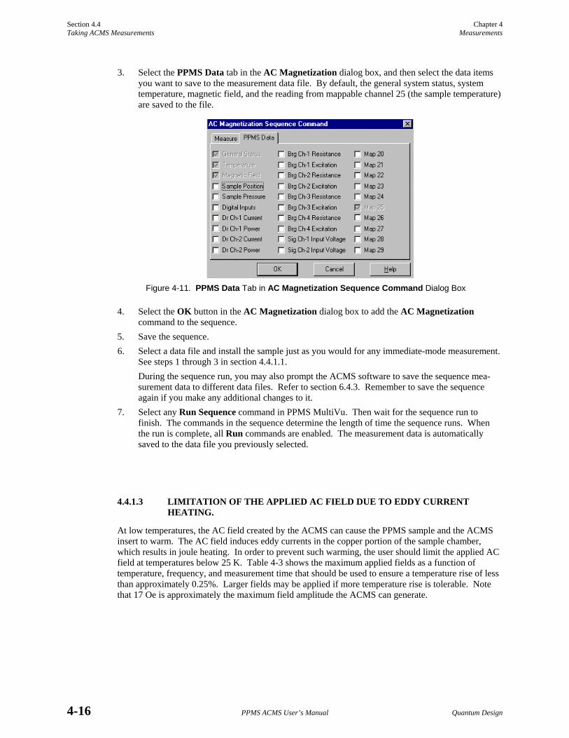
Section 4.4 Chapter 4 Taking ACMS Measurements Measurements
4-16 PPMS ACMS User’s Manual Quantum Design
3. Select the PPMS Data tab in the AC Magnetization dialog box, and then select the data items you want to save to the measurement data file. By default, the general system status, system temperature, magnetic field, and the reading from mappable channel 25 (the sample temperature) are saved to the file.
Figure 4-11. PPMS Data Tab in AC Magnetization Sequence Command Dialog Box
4. Select the OK button in the AC Magnetization dialog box to add the AC Magnetization command to the sequence.
5. Save the sequence. 6. Select a data file and install the sample just as you would for any immediate-mode measurement.
See steps 1 through 3 in section 4.4.1.1. During the sequence run, you may also prompt the ACMS software to save the sequence mea-surement data to different data files. Refer to section 6.4.3. Remember to save the sequence again if you make any additional changes to it.
7. Select any Run Sequence command in PPMS MultiVu. Then wait for the sequence run to finish. The commands in the sequence determine the length of time the sequence runs. When the run is complete, all Run commands are enabled. The measurement data is automatically saved to the data file you previously selected.
4.4.1.3 LIMITATION OF THE APPLIED AC FIELD DUE TO EDDY CURRENT HEATING.
At low temperatures, the AC field created by the ACMS can cause the PPMS sample and the ACMS insert to warm. The AC field induces eddy currents in the copper portion of the sample chamber, which results in joule heating. In order to prevent such warming, the user should limit the applied AC field at temperatures below 25 K. Table 4-3 shows the maximum applied fields as a function of temperature, frequency, and measurement time that should be used to ensure a temperature rise of less than approximately 0.25%. Larger fields may be applied if more temperature rise is tolerable. Note that 17 Oe is approximately the maximum field amplitude the ACMS can generate.
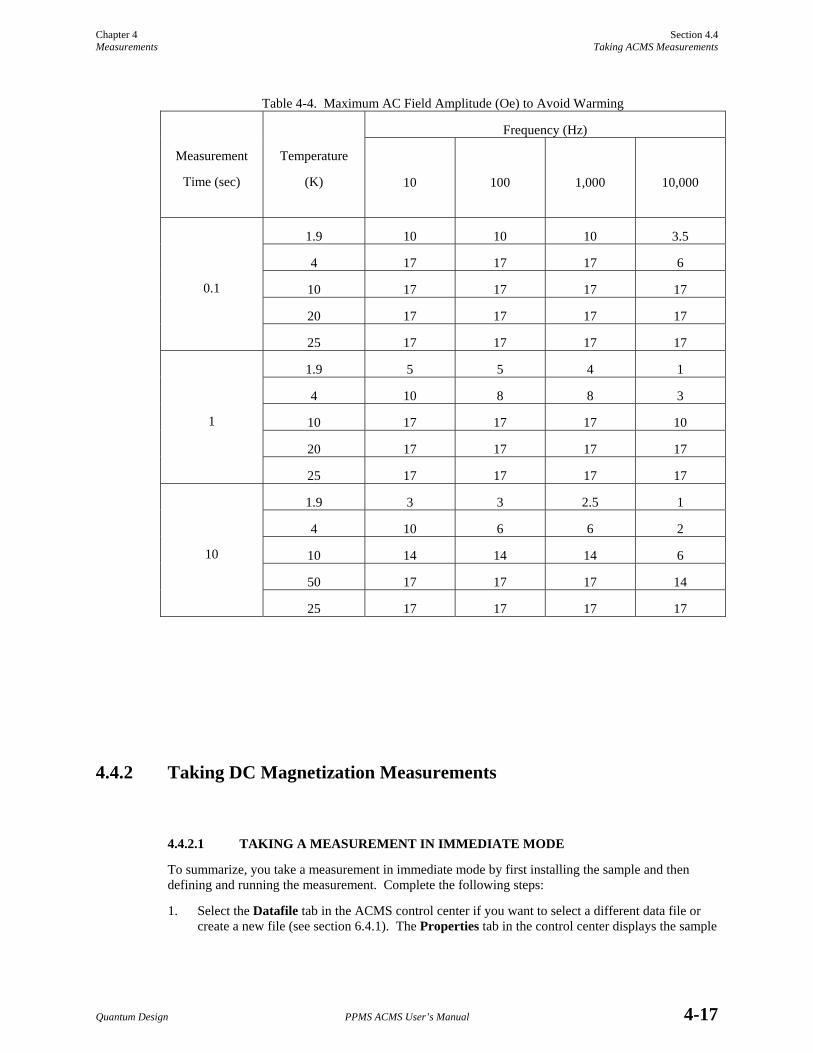
Chapter 4 Section 4.4 Measurements Taking ACMS Measurements
Quantum Design PPMS ACMS User’s Manual 4-17
Table 4-4. Maximum AC Field Amplitude (Oe) to Avoid Warming
Frequency (Hz)
Measurement
Time (sec)
Temperature
(K)
10
100
1,000
10,000
1.9 10 10 10 3.5
4 17 17 17 6
10 17 17 17 17
20 17 17 17 17
0.1
25 17 17 17 17
1.9 5 5 4 1
4 10 8 8 3
10 17 17 17 10
20 17 17 17 17
1
25 17 17 17 17
1.9 3 3 2.5 1
4 10 6 6 2
10 14 14 14 6
50 17 17 17 14
10
25 17 17 17 17
4.4.2 Taking DC Magnetization Measurements
4.4.2.1 TAKING A MEASUREMENT IN IMMEDIATE MODE
To summarize, you take a measurement in immediate mode by first installing the sample and then defining and running the measurement. Complete the following steps:
1. Select the Datafile tab in the ACMS control center if you want to select a different data file or create a new file (see section 6.4.1). The Properties tab in the control center displays the sample
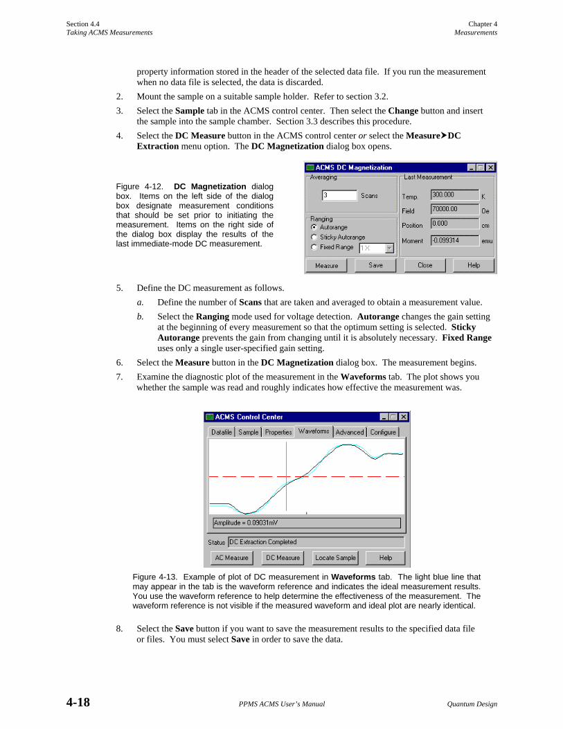
Section 4.4 Chapter 4 Taking ACMS Measurements Measurements
4-18 PPMS ACMS User’s Manual Quantum Design
property information stored in the header of the selected data file. If you run the measurement when no data file is selected, the data is discarded.
2. Mount the sample on a suitable sample holder. Refer to section 3.2. 3. Select the Sample tab in the ACMS control center. Then select the Change button and insert
the sample into the sample chamber. Section 3.3 describes this procedure. 4. Select the DC Measure button in the ACMS control center or select the Measure DC
Extraction menu option. The DC Magnetization dialog box opens.
Figure 4-12. DC Magnetization dialog box. Items on the left side of the dialog box designate measurement conditions that should be set prior to initiating the measurement. Items on the right side of the dialog box display the results of the last immediate-mode DC measurement.
5. Define the DC measurement as follows. a. Define the number of Scans that are taken and averaged to obtain a measurement value. b. Select the Ranging mode used for voltage detection. Autorange changes the gain setting
at the beginning of every measurement so that the optimum setting is selected. Sticky Autorange prevents the gain from changing until it is absolutely necessary. Fixed Range uses only a single user-specified gain setting.
6. Select the Measure button in the DC Magnetization dialog box. The measurement begins. 7. Examine the diagnostic plot of the measurement in the Waveforms tab. The plot shows you
whether the sample was read and roughly indicates how effective the measurement was.
Figure 4-13. Example of plot of DC measurement in Waveforms tab. The light blue line that may appear in the tab is the waveform reference and indicates the ideal measurement results. You use the waveform reference to help determine the effectiveness of the measurement. The waveform reference is not visible if the measured waveform and ideal plot are nearly identical.
8. Select the Save button if you want to save the measurement results to the specified data file or files. You must select Save in order to save the data.
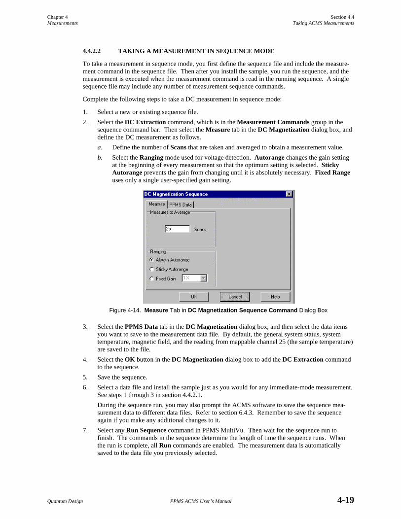
Chapter 4 Section 4.4 Measurements Taking ACMS Measurements
Quantum Design PPMS ACMS User’s Manual 4-19
4.4.2.2 TAKING A MEASUREMENT IN SEQUENCE MODE
To take a measurement in sequence mode, you first define the sequence file and include the measure-ment command in the sequence file. Then after you install the sample, you run the sequence, and the measurement is executed when the measurement command is read in the running sequence. A single sequence file may include any number of measurement sequence commands.
Complete the following steps to take a DC measurement in sequence mode:
1. Select a new or existing sequence file. 2. Select the DC Extraction command, which is in the Measurement Commands group in the
sequence command bar. Then select the Measure tab in the DC Magnetization dialog box, and define the DC measurement as follows. a. Define the number of Scans that are taken and averaged to obtain a measurement value. b. Select the Ranging mode used for voltage detection. Autorange changes the gain setting
at the beginning of every measurement so that the optimum setting is selected. Sticky Autorange prevents the gain from changing until it is absolutely necessary. Fixed Range uses only a single user-specified gain setting.
Figure 4-14. Measure Tab in DC Magnetization Sequence Command Dialog Box
3. Select the PPMS Data tab in the DC Magnetization dialog box, and then select the data items you want to save to the measurement data file. By default, the general system status, system temperature, magnetic field, and the reading from mappable channel 25 (the sample temperature) are saved to the file.
4. Select the OK button in the DC Magnetization dialog box to add the DC Extraction command to the sequence.
5. Save the sequence. 6. Select a data file and install the sample just as you would for any immediate-mode measurement.
See steps 1 through 3 in section 4.4.2.1. During the sequence run, you may also prompt the ACMS software to save the sequence mea-surement data to different data files. Refer to section 6.4.3. Remember to save the sequence again if you make any additional changes to it.
7. Select any Run Sequence command in PPMS MultiVu. Then wait for the sequence run to finish. The commands in the sequence determine the length of time the sequence runs. When the run is complete, all Run commands are enabled. The measurement data is automatically saved to the data file you previously selected.

Quantum Design PPMS ACMS User’s Manual 5-1
C H A P T E R 5
Hardware
5.1 Introduction This chapter contains the following information:
• Section 5.2 lists the main ACMS hardware components.
• Section 5.3 discusses and illustrates the ACMS hardware components.
5.2 Overview of Hardware ACMS system components include the following:
ACMS insert Sample transport/servo controller cable ACMS sample transport Model 6000/servo controller cable ACMS sample holder ACMS preamp cable AC board Palladium calibration sample Servo controller 4-40 thumbscrew
Chapter 2 explains how to install the ACMS insert, ACMS sample transport, and ACMS cables.
The Palladium sample shipped with the ACMS is used to calibrate the ACMS according to Quantum Design service note 1084-302. Quantum Design calibrates each system prior to shipment. However, some customers may require re-calibration in the future. Re-calibration should be performed only by qualified personnel. Note that the Palladium sample should be kept clean.

Section 5.3 Chapter 5 ACMS Hardware Hardware
5-2 PPMS ACMS User’s Manual Quantum Design
5.3 ACMS Hardware
5.3.1 ACMS Insert The ACMS insert houses the drive and detection coils, thermometer, and electrical connections for the ACMS system. You install the ACMS insert directly in the PPMS sample chamber. The insert contains a sample space that lies within the uniform magnetic field region of the PPMS.
The ACMS insert consists of three main components: the sample transport base, baffled rod, and coil set.
• Sample transport base. The sample transport base, which is the top of the ACMS insert, is the mounting base for the ACMS sample transport. The white dot on the sample trans-port base corresponds to the keyed notched at the base of the coil set. When you install the insert, the white dot helps you align the keyed notch on the insert with the key on the base of the PPMS sample chamber.
• Baffled rod. The baffles along the length of the rod provide support inside the PPMS sample chamber. You may thread additional wiring through the baffle vents, although you must take precautions to ensure that air flow through the vent holes is not restricted.
• Coil set. The coil set houses the excitation and detection coil array, which surrounds the sample space. The lowest point of the coil set plugs into the PPMS sample chamber by using the same mechanism as the PPMS sample puck.
The 4-40 thumbscrew included with the ACMS fits into the top of the ACMS insert and helps you handle the insert during installation and removal.
The keyed interface at the base of the coil set on the ACMS insert must periodically be adjusted. Use the standard puck adjustment procedure to adjust the keyed interface.
5.3.1.1 STORAGE
To avoid bending the insert shaft, the ACMS insert should always be supported along its length when it is resting horizontally. The insert may be stored vertically if it is supported by the sample transport base. The coil set and keyed interface in the insert are especially delicate and should always be handled with care.
Figure 5-1. ACMS Insert
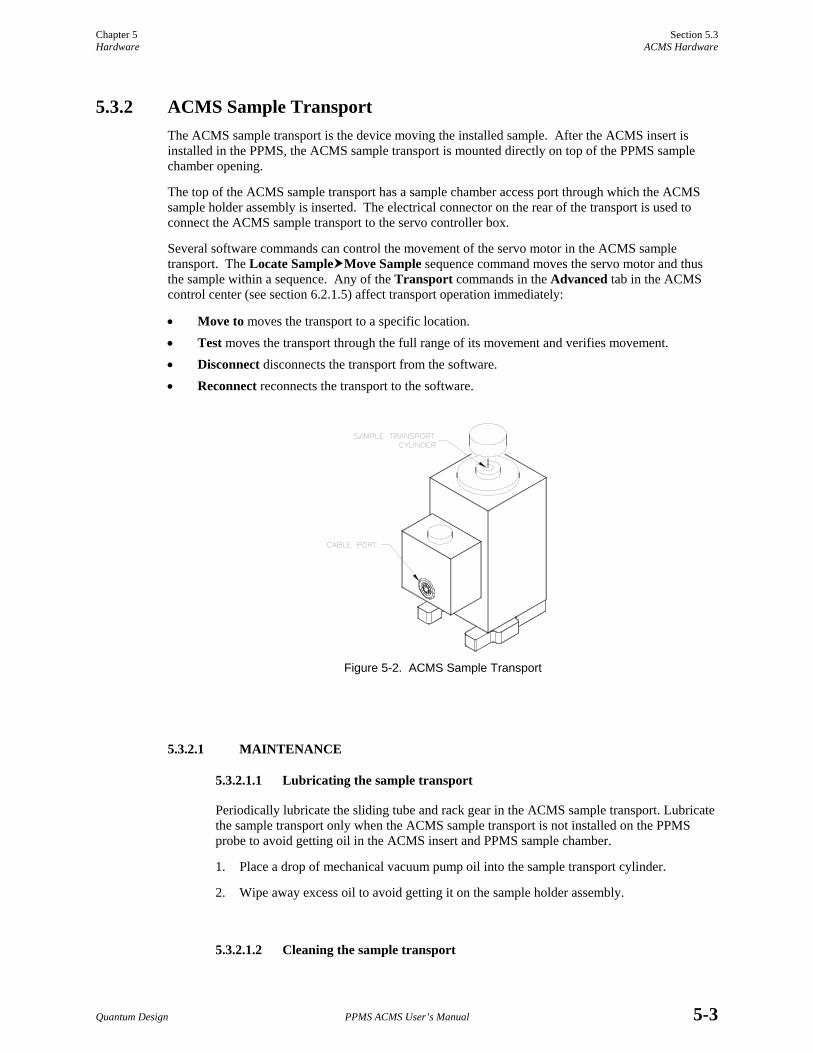
Chapter 5 Section 5.3 Hardware ACMS Hardware
Quantum Design PPMS ACMS User’s Manual 5-3
5.3.2 ACMS Sample Transport The ACMS sample transport is the device moving the installed sample. After the ACMS insert is installed in the PPMS, the ACMS sample transport is mounted directly on top of the PPMS sample chamber opening.
The top of the ACMS sample transport has a sample chamber access port through which the ACMS sample holder assembly is inserted. The electrical connector on the rear of the transport is used to connect the ACMS sample transport to the servo controller box.
Several software commands can control the movement of the servo motor in the ACMS sample transport. The Locate Sample Move Sample sequence command moves the servo motor and thus the sample within a sequence. Any of the Transport commands in the Advanced tab in the ACMS control center (see section 6.2.1.5) affect transport operation immediately:
• Move to moves the transport to a specific location. • Test moves the transport through the full range of its movement and verifies movement. • Disconnect disconnects the transport from the software. • Reconnect reconnects the transport to the software.
Figure 5-2. ACMS Sample Transport
5.3.2.1 MAINTENANCE
5.3.2.1.1 Lubricating the sample transport
Periodically lubricate the sliding tube and rack gear in the ACMS sample transport. Lubricate the sample transport only when the ACMS sample transport is not installed on the PPMS probe to avoid getting oil in the ACMS insert and PPMS sample chamber.
1. Place a drop of mechanical vacuum pump oil into the sample transport cylinder.
2. Wipe away excess oil to avoid getting it on the sample holder assembly.
5.3.2.1.2 Cleaning the sample transport

Section 5.3 Chapter 5 ACMS Hardware Hardware
5-4 PPMS ACMS User’s Manual Quantum Design
A buildup of residue inside the assembly may cause the transport to stick. The system fails when the transport resistance exceeds a vaule that the servo controller assembly can easily drive, and you will see the error message, “Sample Transport is Blocked.” At this point, make sure the assembly is at room temperature and the sample is not installed. If the sample transport is still blocked, clean the sample transport assembly.
Note: Do not use solvents or lubricants to clean the assembly or the block. Also, make sure that the small breaker switch on the rear of the ACMS Servo Controller/Magnet Tray is set. If this breaker is not tripped, it will be very hard to switch. If it has been tripped, it will be easy to reset.
1. Remove the sample transport assembly from the PPMS probe head.
2. From the top of the block positioner, insert a pen-sized instrument (one that won’t scratch any surface of the assembly) into the cylinder. Push the slider tube and gear rack assembly down to the base of the block positioner.
3. Turn the block positioner over and remove the circlip from the bottom of the cylinder. The circlip is the small c-shaped wire that holds the slider tube and gear rack assembly in the block positioner. Removing the circlip allows you to remove the slider tube and gear rack assembly.
4. Use tweezers to rotate the circlip around until it is exposed at the notch. Once the circlip is exposed, use the tweezers to remove it from the cylinder. Be careful not to lose the circlip.
5. Remove the slider tube and gear rack assembly from the cylinder by pushing it down with the pen-sized instrument from the top of the block positioner.
6. Clean the gears and the inner and outer surfaces of the slider tube and gear rack assembly with a dry cotton swab. Next, clean the inside of the block positioner’s cylinder with a cotton swab.
7. After everything is clean, replace the slider tube and gear rack assembly. Insert it, beveled end first, into the cylinder from the bottom of the block positioner and push it up.
8. Replace the circlip. Make sure no part of it is exposed at the notch. Next, replace the sample transport assembly on the PPMS probe head.
5.3.2.1.3 Cleaning the o-rings
Periodically clean the o-rings on the bottom of the ACMS sample transport and under the transport cap. If you still see pressure control problems, inspect the o-rings and replace them with new ones if necessary.
1. Clean with a soft, lint-free cloth.
2. Lightly lubricate with silicone vacuum grease.
5.3.3 ACMS Sample Holder Assembly The sample holder assembly is specifically designed to be used with the ACMS. After the ACMS insert and ACMS sample transport are installed in the PPMS, the sample holder assembly is inserted into the ACMS insert through the access port located on top of the ACMS sample transport.

Chapter 5 Section 5.3 Hardware ACMS Hardware
Quantum Design PPMS ACMS User’s Manual 5-5
The sample holder assembly consists of three main components: the long sample rod, short sample rod, and bucket. These components are constructed of light-weight Delrin to ensure smooth sample transport. The sample rods are suitable for bulk or powdered samples, but are not recommended for liquid samples.
Figure 5-3. ACMS Sample Holder Assembly
Table 5-1. ACMS Mounting Options
PART
PART NUMBER
Sample rod assembly, long 4084-230
Sample rod assembly, short 4084-240
Bucket 4084-239
Storage cap for bucket 4084-235
Sealed sample rod assembly, short 4084-245
Sealed bucket 4084-241
Sealed storage cap for bucket 4084-242
The short sample rod may be replaced with other rods or alternative sample-mounting devices. One alternative mounting device is a clear plastic drinking straw (section 3.2.2). Quantum Design provides adapters that fit on the end of the long ACMS sample rod and hold standard drinking straws.
The sample holder assembly is also available in a sealed variety, so samples may be sealed within the bucket. Both the sealed and non-sealed buckets are supplied with caps to contain the sample when not attached to a sample rod. The various ACMS mounting options are listed in table 5-1. Drinking straw adapter 4084-234
5.3.3.1 MAINTENANCE
To prevent residue from ruining later measurements, you should thoroughly clean sample holder rods after they have been used with powdered samples. Clean the rod with an ultrasonic cleaner and mild solvents or isopropyl alcohol.
The O-rings that are visible on the ACMS sample holder should periodically be cleaned with a soft, lint-free cloth and lightly lubricated with silicone vacuum grease. The frequency of this procedure depends on how often the system is used. If you observe pressure control problems, inspect the O-rings, and if necessary, replace them.
5.3.4 AC Board The AC board houses the electronics that excite the AC drive coils and measure the response signal in the ACMS detection coils. When PPMS systems are shipped with the ACMS option, the AC board

Section 5.3 Chapter 5 ACMS Hardware Hardware
5-6 PPMS ACMS User’s Manual Quantum Design
is installed in the Model 6000 PPMS Controller prior to delivery. The AC board is accessible by the “P3−Option” port on the rear panel of the Model 6000.
A board identical to the AC board is used for the PPMS AC Transport (ACT) option. The AC board is specially calibrated for use with each set of hardware.
5.3.5 Servo Controller The ACMS servo controller provides current to the ACMS servo motor and should be connected to the ACMS sample transport. When PPMS systems are shipped with the ACMS option, the servo controller is installed behind the PPMS magnet controller console, which is in the electronics cabinet, prior to delivery.
Figure 5-4. ACMS Servo Controller
5.3.6 Sample Transport/Servo Controller Cable The sample transport/servo controller cable (part number 3084-290) is the connecting cable for the ACMS option. The cable plugs into the port on the rear panel of the ACMS sample transport and into the “J2 Motor” and “J9 Encoder” ports on the ACMS servo controller. Refer to figure 2-3, “ACMS Connections.”

Chapter 5 Section 5.3 Hardware ACMS Hardware
Quantum Design PPMS ACMS User’s Manual 5-7
Figure 5-5. Sample Transport/Servo Controller Cable
5.3.7 Model 6000/Servo Controller Cable The Model 6000/servo controller cable (part number 3084-289) connects the ACMS board that is inside the Model 6000 PPMS Controller to the ACMS servo controller. The cable plugs into the“P3−Option” port on the Model 6000 and into the “J5 ACMS Board” port on the servo controller. Refer to figure 2-3, “ACMS Connections.”
Figure 5-6. Model 6000/Servo Controller Cable
5.3.8 Preamp Cable The ACMS preamp cable assembly (part number 4084-050) amplifies the signals from the detection coils in the ACMS coil set.
The preamp box plugs into the gray, color-coded port on the PPMS probe head. The two cables that are attached to the preamp box plug into the“P2−System Bridge” and “P3−Option” ports on the Model 6000 PPMS Controller. Refer to figure 2-3, “ACMS Connections.”
Figure 5-7. ACMS Preamp Cable

Quantum Design PPMS ACMS User’s Manual 6-1
C H A P T E R 6
Software
6.1 Introduction This chapter contains the following information:
• Section 6.2 presents an overview of the ACMS software and discusses the ACMS control center.
• Section 6.4 discusses and explains how to create ACMS data files.
• Section 6.3 discusses the ACMS status log.
6.2 Overview of the ACMS Software The ACMS software is integrated into the Windows-based PPMS MultiVu application, so ACMS operation may benefit from the full functionality of PPMS MultiVu, and PPMS MultiVu commands may be used to automate ACMS measurements. For example, within the same PPMS MultiVu sequence file, the ACMS system can take multiple temperature-dependent susceptibility sequences at different fields followed by several DC magnetization measurements at different temperatures. No user intervention is required to perform complex measurements within a single PPMS MultiVu sequence.
DC magnetization measurements and AC susceptibility measurements performed by the ACMS system are defined by user-specified measurement parameters. Measurement results and other relevant parameters reported by the Model 6000 PPMS Controller are stored in ACMS measurement data files.
6.2.1 ACMS Control Center The ACMS software has a control center that includes all frequently selected ACMS commands. With its easy-to-use tab format and software prompts, the ACMS control center makes basic system operations, such as creating data files, installing samples, and setting up and running immediate-mode measurements, more natural and convenient. The ACMS control center opens as soon as the ACMS option is activated, and although it may be minimized, does not close until the option is deactivated. Figures 6-1 through 6-5 illustrate tabs in the ACMS control center.

Section 6.2 Chapter 6 Overview of the ACMS Software Software
6-2 PPMS ACMS User’s Manual Quantum Design
The Status bar at the bottom of the ACMS control center summarizes the general status of the ACMS system. The Status bar indicates the progress of an on-going measurement and summarizes the results of the last measurement. Color-coded warning and error messages in the Status bar alert you to possible problems. Warning messages appear on a yellow background. Error messages appear on a red background. Appendix A lists the warning and error messages.
6.2.1.1 DATAFILE TAB
The Datafile tab identifies which data file or files will save measurement data, and it indicates the highest harmonic that will be saved to the selected data files. If no measurement data file has been selected, the Path, Name, and Title panels in the Datafile tab are blank. Sample measurement data is saved only if a measurement data file is selected. Raw voltage data is saved only if a measurement data file is selected and the Log Raw Data check box is enabled. Measurements may run when a measurement data file is not selected, but the measurement data is discarded.
NOTE
Saving raw voltage data is an option but can be useful under certain conditions. Be aware that raw data files are very large because each individual data point is stored as an entire record and no data reduction is performed. Raw data is saved to a separate raw data file that has the identical base name as the measurement data file, but a .raw file extension instead of a .dat extension.
The View button in the Datafile tab opens the graph view of the selected measurement data file. You can use the Comment button to append a comment to the measurement data file (see section 6.4.2). The comment may be a string of unlimited length.
Figure 6-1. Datafile Tab in ACMS Control Center
You can use the Datafile tab to select or create a data file. The Browse button in the tab opens the ACMS Select Existing or New Data File dialog box, which lists all existing files and lets you create a new measurement data file. When you create a new file, the software prompts you to specify (1) the data file title, which appears above the plot of the graph view of the file; (2) the highest harmonic that will be recorded to the file; and (3) the sample properties. Because the sample property information is stored in the data file header, it can only be specified when the data file is created and cannot be subsequently changed. Section 6.4.1 explains in detail how you create an ACMS data file.

Chapter 6 Section 6.2 Software Overview of the ACMS Software
Quantum Design PPMS ACMS User’s Manual 6-3
6.2.1.2 SAMPLE TAB
The Sample tab is used to initiate insertion of a sample into or removal of a sample from the PPMS sample chamber. The Sample tab also indicates the installed sample’s location relative to the center of the detection coils in the ACMS coil set. The Sample Status panel at the top of the tab always identifies the current status of the sample chamber.
The Change/Finished toggle button in the Sample tab initiates and concludes the sample insertion or removal process. When you select Change, the sample holder assembly is raised and vacuum is lost, so you may remove the sample. Selecting Finished after the sample is removed reestablishes vacuum in the sample chamber. You must select Finished prior to starting any measurements. You may use the Disable Vent/Purge check box that is at the bottom of the Sample tab in order to prevent the state of the system vacuum from changing automatically.
CAUTION
The system should always be at room temperature (298 K) before you attempt to insert or remove a sample, otherwise ice formation and cryopumping of air constituents can cause serious problems with the system.
If the sample insertion or removal process is not completed within 90 seconds, the servo motor is turned off to prevent it from overheating. When the servo motor is turned off, the Motor On button in the Sample tab is enabled. Select Motor On to turn the servo motor back on and complete the sample insertion or removal. Notice that you must still select Finished after you select Motor On.
Figure 6-2. Sample Tab in ACMS Control Center
The Sample Center panel in the Sample tab indicates where the sample is located relative to the detection coils in the ACMS coil set. The AC-DC Offset panel indicates the sample’s center loca- tion as determined by the AC centering or DC centering operation. A large offset indicates that the AC center and/or the DC center measurements had large errors.

Section 6.2 Chapter 6 Overview of the ACMS Software Software
6-4 PPMS ACMS User’s Manual Quantum Design
6.2.1.3 PROPERTIES TAB
The Properties tab lists the sample property information stored in the header of the measurement data file that is identified in the Datafile tab. The sample property information was defined when the data file was created and may not be subsequently changed.
There are no fixed sample properties. The ACMS software does not use the sample properties to determine any data.
6.2.1.4 WAVEFORMS TAB
The Waveforms tab shows a diagnostic plot of the last measurement or centering operation. The actual measured waveform is shown in black. The light blue curve in the display area is the waveform reference, which indicates the ideal measurement results obtained by measuring a sample that is a known calibration standard. The waveform reference line is not visible if the measured waveform and ideal plot are nearly identical.
The plot in the Waveforms tab is overwritten each time another measurement runs.
Plot of AC Centering Scan Plot of AC Measurement
Figure 6-3. Waveforms Tab in ACMS Control Center

Chapter 6 Section 6.2 Software Overview of the ACMS Software
Quantum Design PPMS ACMS User’s Manual 6-5
6.2.1.5 ADVANCED TAB
The Advanced tab contains commands that should be used by only experienced ACMS operators. The Transport commands in the Advanced tab allow the ACMS sample transport to be moved manually or to be disconnected or reconnected to the ACMS software. The Recalibration commands create new calibration files for AC and DC measurements.
The Move to command moves the ACMS sample transport to a specific location. (See section 4.3.5 for more information on moving the sample transport.) The Test command moves the ACMS sample transport through the full range of the transport’s movement and verifies that it moves. Disconnect disconnects the ACMS sample transport from the ACMS software. Reconnect reconnects the trans-port to the software.
The Recalibration commands, which are generally used only with a known sample, create new cali-bration files that are used for all subsequent AC and DC measurements. The Waveform command stores the last DC measurement as a calibration standard. The AC Scale command stores the last AC measurement as a calibration standard.
Figure 6-4. Advanced Tab in ACMS Control Center
The diagnostic mode accessed through the Diagnostics button in the Advanced tab is password protected and is used only by service personnel.

Section 6.2 Chapter 6 Overview of the ACMS Software Software
6-6 PPMS ACMS User’s Manual Quantum Design
6.2.1.6 CONFIGURE TAB
The Configure tab sets several ACMS system settings. You can use the tab to instruct the system to test the DSP or the ACMS sample transport whenever the ACMS option is activated in the PPMS MultiVu software, and you can select the AC excitation mode or the detection technique. The ACMS sample transport is tested by being moved through its full range of motion.
Two AC excitation modes are available. Burst, which is the default mode, activates the drive coils only during the measurement step. Continuous keeps the drive coils activated during the entire measurement process.
The detection technique selection alters the signal analysis routine. Correlating, which is the default mode, uses a sine wave to calculate the sample moment and is preferable under normal measurement circumstances. Integrating uses a square wave.
Figure 6-5. Configure Tab in ACMS Control Center
6.2.1.7 MEASUREMENT COMMAND BUTTONS
The AC Measure, DC Measure, and Locate Sample command buttons in the ACMS control center define and run immediate-mode AC measurements, DC measurements, and centering measurements, respectively. Chapter 4 explains how you use the control center command buttons to run measurements in immediate mode.

Chapter 6 Section 6.4 Software ACMS Data Files
Quantum Design PPMS ACMS User’s Manual 6-7
6.3 ACMS Status Log The ACMS status log records high-level hardware and software activity during ACMS measurements, and during system hardware checks, it records the test results. The ACMS status log also captures warnings, errors, and informational messages that were generated since the ACMS option was last activated in the PPMS MultiVu software. The status log displays the results of only the active ACMS session, although it keeps a record of all ACMS sessions in the log file. The ACMS status log captures more types of information than the PPMS MultiVu event log. The View ACMS Status Log command activates the status log. The name of the default status log file is AcmsLog.
You use the ACMS status log to review a finished measurement or hardware test and to search for any problems that might have occurred. Because the status log records important measurement information, you may be absent when a sequence file runs; you simply review the status log after the sequence run is finished.
Figure 6-6. ACMS Status Log
6.4 ACMS Data Files The ACMS software creates measurement data files and raw measurement data files and stores ACMS measurement data in these files. Measurement data files, which have a .dat file extension, store sam-ple measurement data for any number of measurements taken by either or both of the two measurement types supported by the ACMS option. Raw measurement data files, which have a .raw extension, store raw voltage data for every measurement taken while the raw file is selected. Each raw measure-ment data file is associated with one measurement data file and uses the identical base name as the measurement data file.
The data file header contains file and sample property information that is defined when the measure-ment data file is created. Information written to the data file header cannot be subsequently changed in PPMS MultiVu.
Sample measurement data is saved only if a measurement data file is selected. Raw voltage data is saved only if a measurement data file is selected and the software is prompted to capture raw voltage data. Data is saved to only the selected data file or files. The Datafile tab in the ACMS control center (see figure 6-1) indicates which data file or files will save measurement data. If no measurement data file has been selected, the Path, Name, and Title panels in the Datafile tab are blank.
Data files may be viewed in several different formats. The Physical Property Measurement System: PPMS MultiVu Application User’s Manual discusses the data file format and the multiple data-viewing formats in detail.
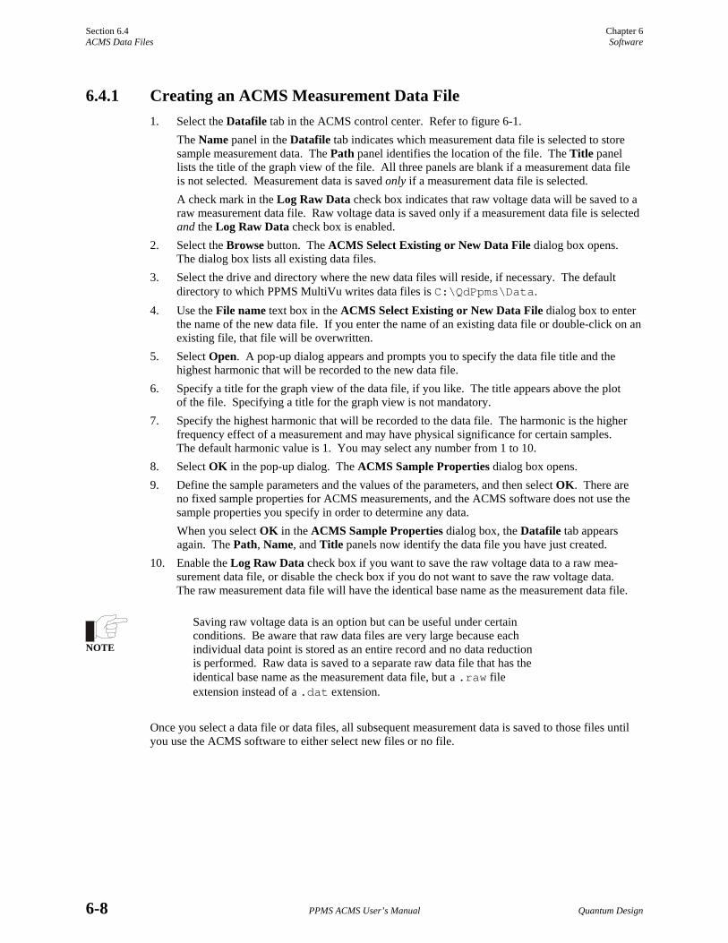
Section 6.4 Chapter 6 ACMS Data Files Software
6-8 PPMS ACMS User’s Manual Quantum Design
6.4.1 Creating an ACMS Measurement Data File 1. Select the Datafile tab in the ACMS control center. Refer to figure 6-1.
The Name panel in the Datafile tab indicates which measurement data file is selected to store sample measurement data. The Path panel identifies the location of the file. The Title panel lists the title of the graph view of the file. All three panels are blank if a measurement data file is not selected. Measurement data is saved only if a measurement data file is selected. A check mark in the Log Raw Data check box indicates that raw voltage data will be saved to a raw measurement data file. Raw voltage data is saved only if a measurement data file is selected and the Log Raw Data check box is enabled.
2. Select the Browse button. The ACMS Select Existing or New Data File dialog box opens. The dialog box lists all existing data files.
3. Select the drive and directory where the new data files will reside, if necessary. The default directory to which PPMS MultiVu writes data files is C:\QdPpms\Data.
4. Use the File name text box in the ACMS Select Existing or New Data File dialog box to enter the name of the new data file. If you enter the name of an existing data file or double-click on an existing file, that file will be overwritten.
5. Select Open. A pop-up dialog appears and prompts you to specify the data file title and the highest harmonic that will be recorded to the new data file.
6. Specify a title for the graph view of the data file, if you like. The title appears above the plot of the file. Specifying a title for the graph view is not mandatory.
7. Specify the highest harmonic that will be recorded to the data file. The harmonic is the higher frequency effect of a measurement and may have physical significance for certain samples. The default harmonic value is 1. You may select any number from 1 to 10.
8. Select OK in the pop-up dialog. The ACMS Sample Properties dialog box opens. 9. Define the sample parameters and the values of the parameters, and then select OK. There are
no fixed sample properties for ACMS measurements, and the ACMS software does not use the sample properties you specify in order to determine any data. When you select OK in the ACMS Sample Properties dialog box, the Datafile tab appears again. The Path, Name, and Title panels now identify the data file you have just created.
10. Enable the Log Raw Data check box if you want to save the raw voltage data to a raw mea-surement data file, or disable the check box if you do not want to save the raw voltage data. The raw measurement data file will have the identical base name as the measurement data file.
NOTE
Saving raw voltage data is an option but can be useful under certain conditions. Be aware that raw data files are very large because each individual data point is stored as an entire record and no data reduction is performed. Raw data is saved to a separate raw data file that has the identical base name as the measurement data file, but a .raw file extension instead of a .dat extension.
Once you select a data file or data files, all subsequent measurement data is saved to those files until you use the ACMS software to either select new files or no file.

Chapter 6 Section 6.4 Software ACMS Data Files
Quantum Design PPMS ACMS User’s Manual 6-9
6.4.2 Adding a Comment to an ACMS Measurement Data File You may append a comment to the ACMS measurement data file that is selected to store measurement data. Comments are useful to record changes in operation or any other type of information about the experiment that it would be helpful for you or for anyone else who might read the data file to know. A comment may be a string of unlimited length. The quotation mark (") is not permitted in comments.
You may append a comment to the data file immediately, or you may include the comment in a sequence so that the comment is appended to the data file when the sequence runs.
• To append a comment to the data file immediately, select the Comment button that is in the Datafile tab in the ACMS control center (see figure 6-1), and then enter the comment and select OK.
• To append a comment to the data file at a later time, select the Datafile Comment sequence command, which is in the Measurement Commands group in the sequence command bar, and then enter the comment and select OK. The comment appears in the sequence editor, but is not added to the data file until the sequence runs.
Figure 6-7. ACMS Datafile Comment Dialog Box
To view comments that have been added to the selected data file, you open the raw data view of the file and scroll down through the data until you find the comments.
6.4.3 Changing ACMS Data Files during a Sequence Run During a sequence run, you may prompt the ACMS software to save sequence measurement data to new or different data files or to stop saving raw voltage data to a raw measurement data file. The New Datafile sequence command instructs PPMS MultiVu to start saving data to whatever file or files are selected by New Datafile. The New Datafile command is in the Measurement Commands group in the sequence command bar.
Selecting the New Datafile command opens the Change Datafile dialog box (see figure 6-8). You use the Datafile tab in the Change Datafile dialog box to select a measurement data file and, if you want to record raw voltage data, to prompt PPMS MultiVu to save raw data to the measurement data file’s associated raw data file. Deselecting the Record Raw Data check box prompts PPMS MultiVu to stop saving raw data.
You may use New Datafile to select an existing data file or to create a new data file. Refer to section 6.4.1 to review the procedures you follow to create a new data file.
Before you select the data file to which you will append data, you should open the Sample tab in the Change Datafile dialog box. The Sample tab, which is identical to the Properties tab in the ACMS control center, lists the sample property information stored in the header of the selected data file. Choose a different data file if the sample property information does not match your sample. If you append data to a file, you cannot change the title of the file, the value of the highest harmonic that is recorded to the file, or any of the sample property information that is stored in the data file header.

Section 6.4 Chapter 6 ACMS Data Files Software
6-10 PPMS ACMS User’s Manual Quantum Design
Figure 6-8. Datafile Tab in Change Datafile Dialog Box
In the sequence file, the New Datafile command must precede a sequence measurement command in order to instruct the ACMS software to save data generated by that measurement to the new data files.

Quantum Design PPMS ACMS User’s Manual A-1
A P P E N D I X A
Error and Warning Messages
A.1 Introduction This appendix contains the following information:
• Section A.2 lists the system start-up error and warning messages.
• Section A.6 lists the DC measurement error and warning messages.
• Section A.3 lists the general system error and warning messages.
• Section A.7 lists the DSP I/O error and warning messages.
• Section A.4 lists the sample centering error and warning messages.
• Section A.8 lists the servo controller error and warning messages.
• Section A.5 lists the AC measurement error and warning messages.
Warning messages appear on a yellow background in the status bar that is at the bottom of the ACMS control center. Error messages appear on a red background. Warning messages indicate a minor hardware or software problem. If a measurement is in progress when a warning message appears, the measurement results will be suspect. Error messages indicate a serious hardware or software problem. If a measurement is in progress when an error message appears, the measurement results will be wrong.
If an error message appears, you should investigate the cause of the problem before you use the system to perform any other operations. If the error message indicates a software problem, you should restart PPMS MultiVu and reactivate the ACMS option.

Section A.2 Appendix A System Start-Up Error and Warning Messages Error and Warning Messages
A-2 PPMS ACMS User’s Manual Quantum Design
A.2 System Start-Up Error and Warning Messages
MESSAGE TYPE EXPLANATION
DSP failure to initialize. Error Application failed to reset DSP after several tries.
DSP failure to initialize, check connections.
Error Application cannot communicate with DSP.
DSP failed to initialize, going offline.
Error Application abandoned attempts to communicate with DSP. DSP will be put into simulation mode.
ACMS DSP running in simulation mode.
Warning Application is simulating DSP.
ACMS transport running in simulation mode.
Warning Application is simulating servo transport.
DC calibration file missing. DC measures are not calibrated.
Warning dc-emu.cal file is missing. Computed DC emu values will be wrong.
Missing sample thermometer calibration file: <CalFile>.
Warning dc-therm.cal file is missing. Application will use system thermometer.
Sample thermometer is not working, using system thermometer.
Warning Application cannot read sample thermometer and is using system thermometer for temperature readings, thus causing inaccuracies in results.

Appendix A Section A.4 Error and Warning Messages Centering Error and Warning Messages
Quantum Design PPMS ACMS User’s Manual A-3
A.3 General Error and Warning Messages
MESSAGE TYPE EXPLANATION
Set temperature (T) is over 350 K, may harm coilset.
Error Application has detected a set temperature greater then 350 K.
No signal detected for this measurement.
Error A zero-amplitude signal was read by DSP. Check connections.
Signal too large at lowest gain. Error Signal amplitude exceeded 90% of maximum voltage input of DSP.
Signal too large at selected gain. Error Signal amplitude exceeded 90% of maximum voltage input of DSP.
Small signal at highest gain. Warning Signal amplitude is less then 1% of maximum voltage input of DSP.
Small signal at selected gain. Warning Signal amplitude is less then 1% of maximum voltage input of DSP.
Servo travel blocked. Warning Application unable to move servo to new position.
Unable to change datafile, not an ACMS datafile <file>.
Warning New Datafile sequence command found non-ACMS data file.
Unable to change datafile, incorrect ACMS version <file>.
Warning New Datafile sequence command found old ACMS data file.
A.4 Centering Error and Warning Messages
MESSAGE TYPE EXPLANATION
Cannot start AC centering. Warning Error occurred in starting AC centering.
Cannot start DC centering. Warning Error occurred in starting DC centering.
Unable to locate sample. Warning Error occurred in the locate data and the locate was cancelled.

Section A.6 Appendix A DC Measurement Error and Warning Messages Error and Warning Messages
A-4 PPMS ACMS User’s Manual Quantum Design
A.5 AC Measurement Error and Warning Messages
MESSAGE TYPE EXPLANATION
Measurement not taken due to errors.
Error Previous errors have invalidated measurement.
Measurement did not complete, canceling.
Error A timeout from previous message indicates measurement will be cancelled.
Cannot set requested drive, using <h> Oe.
Warning Requested drive is too large for coil. Smaller drive will be used.
Unable to move sample to required position.
Warning Application unable to move sample to top, bottom, or center.
Internal math error: drive phase or consistency check failed.
Warning Unexpected error indicates that measurement is bad.
Unable to apply calibration correction --- no signal detected.
Warning No signal detected for measurement.
Measurement unexpectedly already in progress, waiting . . .
Warning DSP is completing a measurement (may be a serious error).
A.6 DC Measurement Error and Warning Messages
MESSAGE TYPE EXPLANATION
Incorrect DC scans count. Requested = <m>, Actual = <n>.
Error Servo motor made too few (or too many) scans of sample.
Sample is too far off-center for DC measurements.
Error Measured signal was trimmed by servo limits and is unusable.
Cannot calculate sample position, using zero.
Warning DC center signal was too poor to use to determine center position.
Using nearest sample position in accessible region <x> to <y>.
Warning Requested sample travel is outside servo motor limits.
No data measured for DC measurement.
Warning No signal detected for DC measurement.

Appendix A Section A.8 Error and Warning Messages Servo Controller Error and Warning Messages
Quantum Design PPMS ACMS User’s Manual A-5
A.7 DSP I/O Error and Warning Messages
MESSAGE TYPE EXPLANATION
DSP unable to run reliably, going offline.
Error Problem occurred with DSP or with GPIB communications. May be random and may be correctable or recoverable.
DSP discarding measurement. Error Problem occurred with DSP or with GPIB communications. May be random and may be correctable or recoverable.
DSP cannot be cleared. Warning Application deactivate cannot clear DSP.
DSP internal consistency failed. Warning Problem occurred with DSP or with GPIB communications. May be random and may be correctable or recoverable.
DSP error detected and corrected.
Warning Problem occurred with DSP or with GPIB communications. May be random and may be correctable or recoverable.
DSP wrong packet length returned.
Warning Problem occurred with DSP or with GPIB communications. May be random and may be correctable or recoverable.
DSP incorrect checksum, re-fetching packet.
Warning Problem occurred with DSP or with GPIB communications. May be random and may be correctable or recoverable.
DSP SendRead packet length, requested = 1, actual = <w>.
Warning Problem occurred with DSP or with GPIB communications. May be random and may be correctable or recoverable.
DSP unable to get status. Warning Problem occurred with DSP or with GPIB communications. May be random and may be correctable or recoverable.
A.8 Servo Controller Error and Warning Messages The following are exception dialogs the application might display during servo controller initialization:
*Could not open port *Could not read CommState *Could not set CommState *Could not set DTR *Could not set CommTimeouts *Could not setup EscapeCommFunction *Could not set baud rate *Could not initialize servo-controller

Section A.8 Appendix A Servo Controller Error and Warning Messages Error and Warning Messages
A-6 PPMS ACMS User’s Manual Quantum Design
MESSAGE TYPE EXPLANATION
Servo controller unable to recover.
Error Errors have forced application to abandon communications with servo.
Unrecoverable servo controller error, unable to continue experiment!
Error Application will halt all measurement activity until user corrects the problem.
Servo controller is not connected.
Error Measurement attempted to use servo and servo was off-line.
Servo has been reset, initializing servo . . .
Warning Application detected that servo was reset (perhaps a power problem) and is attempting to re-initialize servo.
Servo controller error: <error>, retrying . . .
Warning This error can occur in servo communications. Application will attempt to retry for a limited time before abandoning communication.
Servo controller error: <error>. Warning This error can occur in servo communications. Application will attempt to retry for a limited time before abandoning communication.
The following servo errors are returned by the application:
Servo Not Connected RS232 Read Failure Read Timeout No Reply RS232 Write Failure Servo Move Failure Cannot Communicate to Servo No Reply to Escape Servo Move Inaccurate Servo Reset Occurred Servo Memory Loss Occurred Servo Register Loss Occurred
The following servo errors are returned by the servo controller:
Argument Error Invalid Command Invalid Macro Cmd Macro Arg Err Macro Not Defined Macro Out of Range Out Of Macro Space Def Macro in Macro Def Macro when Servo Enabled Macro Jump Error Out of Macro Heap Space Macro Must be 1st Command

Quantum Design PPMS ACMS User’s Manual References-1
References
Quantum Design. 2000. Physical Property Measurement System: Hardware Manual.
⎯⎯⎯. 2000. Physical Property Measurement System: PPMS MultiVu Application User’s Manual.
⎯⎯⎯. 1996. Service note 1084-302, Calibration Procedure for the PPMS P500 AC Susceptibility and DC Magnetization Option (ACMS).
⎯⎯⎯. 1999. Using the Fiber Optic Sample Holder (FOSH) for the ACMS.

Quantum Design PPMS ACMS User’s Manual Index-1
Index
AC 1-4, 5-5 AC board, 1-4, 5-5 AC centering advisability of, 4-5 comparison with DC centering, 4-3, 4-5 in immediate mode, procedures for, 4-7−4-8 operating modes, 4-4 plot, example of, 4-7 process, 4-6, 4-7 in sequence mode, procedures for, 4-8 warning messages, A-3 AC excitation modes, 6-6 AC, field amplitude, 4-16 ACMS control center measurement command buttons, 6-6 overview, 6-1 status bar, 6-2 tabs, 6-2−6-6 ACMS insert adjusting keyed interface, 5-2 function, 1-1, 5-2. See also Detection coils; Drive coil illustration, 1-3, 5-2 installing in PPMS, 2-1, 2-2 sample in, 3-4 warming, 4-16 removing, 2-5 storing, 5-2 AcmsLog file, 6-7 ACMS measurement data files adding comment to, 6-9 automatically saving sequence data, 4-16 changing during sequence run, 6-9−6-10 creating, 6-8 opening graph view, 6-2 sample property data, displayed in Properties tab, 6-4 saving data to, 4-4, 6-2, 6-7 selected, identified in Datafile tab, 6-2, 6-7 ACMS option activating, 2-4 calibrating, 5-1 data files. See Data files electronics, 1-4 hardware, 5-1. See also AC board; ACMS insert; ACMS sample holder; ACMS sample transport; Cables; Servo controller installing, 2-1−2-4 maximum temperature, 1-2 measurements. See AC susceptibility measurements; DC magnetization measurements
overview, 1-1 probe magnetics, 1-2−1-3 removing, 2-5 safety precautions, 1-5−1-6 sample centering. See AC centering; DC centering software, overview of, 6-1. See also ACMS control center; ACMS measurement data files; ACMS raw measurement data files; ACMS status log ACMS raw measurement data files creating, 6-8 saving data to, 6-2, 6-7 selected, identified in Datafile tab, 6-2 ACMS sample holder function, 5-4 maintenance, 5-4 mounting sample on, 3-1, 3-2 ACMS sample transport controlling movement of, 4-10, 5-3, 6-5 disconnecting from software, 5-3, 6-5 function, 5-3 installing, 2-1, 2-2−2-3 maintenance, 5-3 removing, 2-5 testing manually, 4-10, 5-3, 6-5 when ACMS is activated, 6-6 ACMS status log, 6-7 ACMS view tree, 4-15 AC susceptibility measurements centering sample prior to taking, 4-11 comparison with DC measurements, 4-3 creating calibration file for, 6-5 error messages, A-1, A-4 in immediate mode, procedures for, 4-11−4-13 measure modes, 4-12 multiple, taking in sequence, 4-13−4-16 operating modes, 4-4 plot, example of, 4-13 process, 4-1, 4-2. See also ACMS option: Probe magnetics reviewing results in ACMS status log, 6-7 in sequence mode, procedures for, 4-17−4-19 time, 4-16 warning messages, A-1, A-4 Advanced tab, 6-5 Amplitude spacing modes, 4-14 Autorange mode, 4-12, 4-15,4-18-4-19

Index
Index-2 PPMS ACMS User’s Manual Quantum Design
Baffled rod, on ACMS insert, 5-2 Bucket, for ACMS sample holder, 5-4 Burst excitation mode, 6-6 Cables connections, illustration of, 2-4 description, 5-6 Calibration coils, 1-2, 1-3, 4-2 Centering. See AC centering; DC centering Coil set, on ACMS insert, 5-2. See also Detection coils; Drive coil Comment, adding to data file, 6-9 Compensation coil function, 1-2 illustration, 1-3 Configure tab, 6-6 Connections, illustration of, 2-4 Continuous excitation mode, 6-6 Control center. See ACMS control center Correlating detection technique, 6-6 Cryogens, safety precautions for, 1-5 Datafile Comment sequence command, 6-9 Data file header, 6-7 Data files adding comment to, 6-9 changing during sequence run, 6-9−6-10 creating, 6-8 default directory, 6-8 saving data to, 4-4, 6-2, 6-7 selected, identified in Datafile tab, 6-2, 6-7 types, 6-7 viewing formats, 6-7 Datafile tab, 6-2 DC-AC offset, 4-6, 4-7 DC centering advisability of, 4-5 comparison with AC centering, 4-3, 4-5 in immediate mode, procedures for, 4-8−4-9 operating modes, 4-4 plot, example of, 4-9 process, 4-6−4-7 in sequence mode, procedures for, 4-9 warning messages, A-3 DC extraction. See DC centering DC magnetization measurements centering sample prior to taking, 4-11 comparison with AC measurements, 4-3 creating calibration file for, 6-5 error messages, A-1, A-4 in immediate mode, procedures for, 4-17 operating modes, 4-4 plot, example of, 4-17 process, 4-1, 4-3. See also ACMS option: Probe magnetics reviewing results in ACMS status log, 6-7 in sequence mode, procedures for, 4-18 warning messages, A-1, A-4
DC servo motor. See Servo motor Detection coils function, 1-2, 1-3 illustration, 1-3 and sample centering. See AC centering; DC centering Detection techniques, 6-6 Diagnostic mode, 6-5 Drive coil excitation modes, 6-6 function, 1-2 illustration, 1-3 DSP testing when ACMS is activated, 6-6 warning messages, A-5 Eddy Current Heating, 4-16 Error messages, A-1−A-6 Five-point measurement process, 4-2 suggested use, 4-12 Fixed range, 4-12,4-15, 1-18-4-19 Frequency spacing modes, 4-15 Hardware installing, 2-1−2-4 overview, 5-1 removing, 2-5 Harmonic, highest, saving to data file, 6-2, 6-8 High-Vacuum option, effect on transport installation, 2-3 Immediate mode centering. See AC centering; DC centering comparison with sequence mode, 4-4 measurements. See AC susceptibility measurements; DC magnetization measurements Installation hardware, 2-1−2-4 sample, 3-4 Integrating detection technique, 6-6 Magnet, safety precautions for, 1-5 Maintenance ACMS insert, 5-2 ACMS sample holder, 5-4 ACMS sample transport, 5-3 Measurement data, saving. See ACMS measurement data files: Saving data to Measurements. See AC susceptibility measurements; DC magnetization measurements Measure modes, 4-12-4-19 Model 6000 PPMS Controller ACMS cables connected to, 5-6 housing AC board, 1-4, 5-5 Model 6000/servo controller cable, 5-6 New Datafile sequence command, 6-9−6-10

Index
Quantum Design PPMS ACMS User’s Manual Index-3
Palladium calibration sample, 5-1 PPMS sample chamber, warming, 4-16 Preamp cable, 5-6 Primary scan mode, 4-14 Properties tab, 6-4 Ranging modes, 4-12,4-18-4-19 Raw voltage data saving, 6-2 switching save option during sequence run, 6-9−6-10 Recalibration commands, 6-5 Safety precautions, 1-5−1-6 Sample centering. See AC centering; DC centering characteristics, influencing measurement method, 4-3 installing, 3-4 measuring. See AC susceptibility measurements; DC magnetization measurements mounting on ACMS sample holder, 3-1, 3-2 on drinking straw, 3-1, 3-3 options, list of, 5-4 moving independently, 4-10, 5-3, 6-5 property data, displayed in Properties tab, 6-4 removing, 3-5 specifying location of, 4-9 types, suitable for ACMS sample holder, 5-4 Sample holder. See ACMS sample holder Sample rod assemblies, for ACMS sample holder, 5-4 Sample tab, 6-3. See also Sample: Installing Sample transport. See ACMS sample transport Sample transport/servo controller cable, 5-6 Sequence mode centering. See AC centering; DC centering comparison with sequence mode, 4-4 measurements. See AC susceptibility measurements; DC magnetization measurements Servo controller error messages, A-6 exception dialogs, A-5 function, 1-4, 5-5 warning messages, A-6 Servo motor controlling movement of, 5-3, 6-5 moving sample, 1-1, 1-3 and sample centering, 4-5 turning on, 6-3 Software, overview of, 6-1. See also ACMS control center; ACMS measurement data files; ACMS raw measurement data files; ACMS status log Status log. See ACMS status log Sticky autorange, 4-12 System start-up warning messages, A-2
Temperature changes, effect on centering, 4-5, 4-11 maximum, 1-2, 4-16 rise, 4-16 Thermometers, 1-4 Warning messages, A-1−A-6 Waveform reference, 6-4 Waveforms tab,4-13,4-18, 6-4