ph 210 ph 211 ph 212 ph 213 - pewa
TRANSCRIPT
1
Functions
pH Calibration
pH213Microprocessor pH
Meter
Confirm 2Buffer
nd
CFMSelect 2
Buffer
nd
/Confirm 1 Buffer
st
CFM
/Select 1
Buffer
st
Start Calibration
CALCOMMRS232 Communication
MRMemory RecallSelect pH / ORP
RANGE
MEMMemorize Reading
MR
MEM
COMM
C
C
RANGE
CFM
CAL
Instruction Manual
Microprocessor-basedpH/mV/°C
Bench Meters
pH 210 pH 211pH 212 pH 213
www.hannainst .com
2 3
pH 210, pH 211, pH 212 and pH 213 are guaranteed for two years againstdefects in workmanship and materials when used for their intended purpose andmaintained according to instructions. Electrodes and probes are guaranteed forsix months. This warranty is limited to repair or replacement free of charge.Damage due to accidents, misuse, tampering or lack of prescribed maintenanceis not covered.If service is required, contact the dealer from whom you purchased the instrument.If under warranty, report the model number, date of purchase, serial number andthe nature of the problem. If the repair is not covered by the warranty, you will benotified of the charges incurred. If the instrument is to be returned to Hanna Instru-ments, first obtain a Returned Goods Authorization number from the TechnicalService department and then send it with shipping costs prepaid. When shippingany instrument, make sure it is properly packed for complete protection. The Hanna pH 210, pH 211, pH 212 and pH 213 are microprocessor-
based pH and Temperature bench meters.pH 211 and pH 213 can also measure ion concentration (ISE) andOxidation Reduction Potential (ORP) in the mV range.pH measurements are compensated for temperature effect manually orautomatically with the HI 7669/2W temperature probe.The instrument is equipped with a large easy-to-read LCD which showsthe pH (or mV) and temperature simultaneously, together with graphicsymbols.The calibration process is guided step by step through clear indications onthe LCD. A stability indicator makes the calibration procedure error-free.Through the RS232 serial port data can be transferred to a PC(pH 212 and pH 213 only).
Remove the instrument from the packing material and examine itcarefully to make sure that no damage has occurred during shipping.If there is any damage, notify your Dealer or the nearest HannaCustomer Service Center.Each instrument is supplied with:
• HI 1131B Glass-body Combination pH Electrode• HI 7669/2W Temperature Probe• HI 76404 Electrode Holder• pH 4.01 & 7.01 Buffer Solutions, 20 mL each• HI 7071S Electrolyte Solution• 12VDC Power Adapter• Instruction Manual
Note: Save all packing material until you are sure that theinstrument functions correctly. All defective items must bereturned in the original packing with the supplied accessories.
WARRANTY .................................................................................. 2PRELIMINARY EXAMINATION ........................................................ 3GENERAL DESCRIPTION ................................................................ 3FUNCTIONAL DESCRIPTION pH 210 AND pH 211 ......................... 4pH 210 AND pH 211 SPECIFICATIONS ........................................ 5FUNCTIONAL DESCRIPTION pH 212 AND pH 213 ......................... 6pH 212 AND pH 213 SPECIFICATIONS ........................................ 7OPERATIONAL GUIDE ................................................................... 8pH CALIBRATION ....................................................................... 11TEMPERATURE CALIBRATION (for technical personnel only) ........... 14mV CALIBRATION (pH 213 only) (for technical personnel only) .... 16PC INTERFACE (pH 212 & pH 213 only) .................................... 17pH BUFFER TEMPERATURE DEPENDENCE ...................................... 19ELECTRODE CONDITIONING & MAINTENANCE ............................... 20TROUBLESHOOTING GUIDE ........................................................ 23TEMPERATURE CORRELATION FOR pH SENSITIVE GLASS ................. 24ACCESSORIES ............................................................................. 25
TABLE OF CONTENTSTABLE OF CONTENTSTABLE OF CONTENTSTABLE OF CONTENTSTABLE OF CONTENTS
Dear Customer,Thank you for choosing a Hanna Instruments product.Please read this instruction manual carefully before using the instruments.This manual will provide you with the necessary information for correct use ofthe instruments, as well as a precise idea of their versatility.If you need additional technical information, do not hesitate to e-mail us [email protected] or turn the back cover for our worldwide contact list.These instruments are in compliance with directives.
WARRANTYWARRANTYWARRANTYWARRANTYWARRANTY
PREL IMINARY EXAMINATIONPRELIMINARY EXAMINATIONPRELIMINARY EXAMINATIONPRELIMINARY EXAMINATIONPRELIMINARY EXAMINATION
GENERAL DESCRIPTIONGENERAL DESCRIPTIONGENERAL DESCRIPTIONGENERAL DESCRIPTIONGENERAL DESCRIPTION
Hanna Instruments reserves the right to modify the design,construction and appearance of its products without advance notice.
4 5
pppppH 210 AND H 210 AND H 210 AND H 210 AND H 210 AND pppppH 211H 211H 211H 211H 211SPECIF ICATIONSSPECIF ICATIONSSPECIF ICATIONSSPECIF ICATIONSSPECIF ICATIONS
FUNCTIONAL DESCRIPTIONFUNCTIONAL DESCRIPTIONFUNCTIONAL DESCRIPTIONFUNCTIONAL DESCRIPTIONFUNCTIONAL DESCRIPTIONpppppHHHHH 210 AND 210 AND 210 AND 210 AND 210 AND pppppHHHHH 211 211 211 211 211
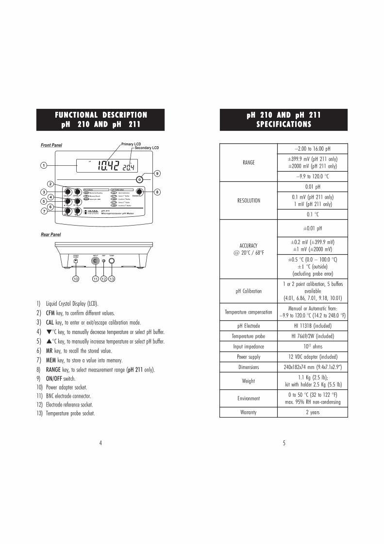
1) Liquid Crystal Display (LCD).2) CFM key, to confirm different values.3) CAL key, to enter or exit/escape calibration mode.4) °C key, to manually decrease temperature or select pH buffer.5) °C key, to manually increase temperature or select pH buffer.6) MR key, to recall the stored value.7) MEM key, to store a value into memory.8) RANGE key, to select measurement range (pH 211 only).9) ON/OFF switch.10) Power adapter socket.11) BNC electrode connector.12) Electrode reference socket.13) Temperature probe socket.
EGNAR
Hp00.61ot00.2–
± )ylno112Hp(Vm9.993± )ylno112Hp(Vm0002
C°0.021ot9.9–
NOITULOSER
Hp10.0
)ylno112Hp(Vm1.0)ylno112Hp(Vm1
C°1.0
YCARUCCAF°86/C°02@
± Hp10.0
± (Vm2.0 ± )Vm9.993± (Vm1 ± )Vm0002
± )C°0.001–0.0(C°5.01± )edistuo(C°
)rorreeborpgnidulcxe(
noitarbilaCHpsreffub5,noitarbilactniop2ro1
elbaliava)10.01,81.9,10.7,68.6,10.4(
noitasnepmocerutarepmeT:morfcitamotuArolaunaM
)F°0.842ot2.41(C°0.021ot9.9–
edortcelEHp )dedulcni(B1311IH
eborperutarepmeT )dedulcni(W2/9667IH
ecnadepmitupnI 01 21 smho
ylppusrewoP )dedulcni(retpadaCDV21
snoisnemiD )”9.2x1.7x4.9(mm47x281x042
thgieW;)bl5.2(gK1.1
)bl5.5(gK5.2redlohhtiwtik
tnemnorivnE)F°221ot23(C°05ot0
gnisnednoc-nonHR%59.xam
ytnarraW sraey2
Front Panel Primary LCDSecondary LCD
1
9
3
2
7
4
6
5
8
Rear Panel
POWER
12VDC
INPUT TEMPREF
10 12 1311
Functions pH Calibration
pH 211
Microprocessor pH Meter
Confirm 2 Buffernd
CFM
Select 2 Buffer
nd
/
Confirm 1 Bufferst
CFM
/ Select 1 Bufferst
Start CalibrationCAL
MR Memory Recall
Select pH / ORPRANGE
MEM Memorize Reading
MRMEM
CC
RANGECFMCAL
pH
C
6 7
ppppp HHHHH 212 AND 212 AND 212 AND 212 AND 212 AND ppppp HHHHH 2 1 32 1 32 1 32 1 32 1 3SPECIF ICATIONSSPECIF ICATIONSSPECIF ICATIONSSPECIF ICATIONSSPECIF ICATIONS
FUNCTIONAL DESCRIPTIONFUNCTIONAL DESCRIPTIONFUNCTIONAL DESCRIPTIONFUNCTIONAL DESCRIPTIONFUNCTIONAL DESCRIPTIONppppp HHHHH 212 AND 212 AND 212 AND 212 AND 212 AND ppppp HHHHH 2 1 32 1 32 1 32 1 32 1 3
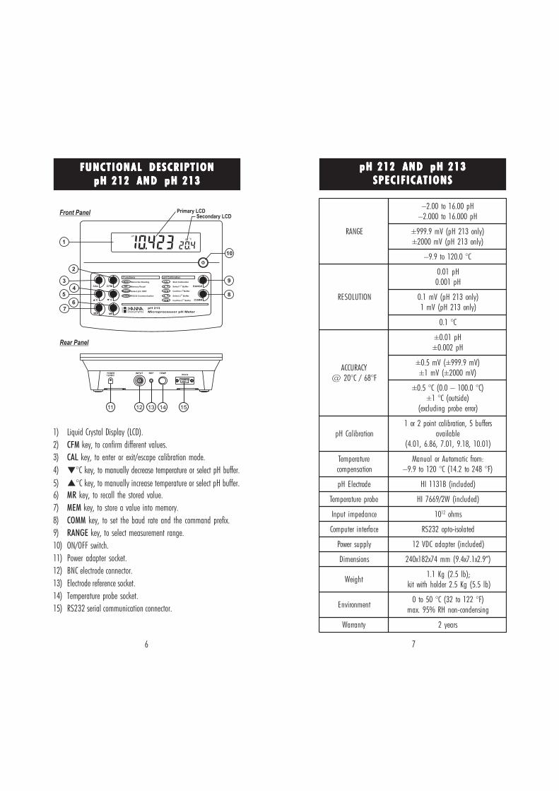
1) Liquid Crystal Display (LCD).2) CFM key, to confirm different values.3) CAL key, to enter or exit/escape calibration mode.4) °C key, to manually decrease temperature or select pH buffer.5) °C key, to manually increase temperature or select pH buffer.6) MR key, to recall the stored value.7) MEM key, to store a value into memory.8) COMM key, to set the baud rate and the command prefix.9) RANGE key, to select measurement range.10) ON/OFF switch.11) Power adapter socket.12) BNC electrode connector.13) Electrode reference socket.14) Temperature probe socket.15) RS232 serial communication connector.
Front Panel Primary LCDSecondary LCD
1
93
2
7
4
6
5
10
8
Rear Panel
POWER
12VDC
INPUT TEMPRS232
REF
11 13 14 1512
Functions pH Calibration
pH 213
Microprocessor pH Meter
Confirm 2 Buffernd
CFM
Select 2 Buffer
nd
/
Confirm 1 Bufferst
CFM
/ Select 1 Bufferst
Start CalibrationCAL
COMM RS232 Communication
MR Memory Recall
Select pH / ORPRANGE
MEM Memorize Reading
MRMEM
COMMCC
RANGECFMCAL
EGNAR
Hp00.61ot00.2–Hp000.61ot000.2–
± )ylno312Hp(Vm9.999± )ylno312Hp(Vm0002
C°0.021ot9.9–
NOITULOSER
Hp10.0Hp100.0
)ylno312Hp(Vm1.0)ylno312Hp(Vm1
C°1.0
YCARUCCAF°86/C°02@
± Hp10.0± Hp200.0
± (Vm5.0 ± )Vm9.999± (Vm1 ± )Vm0002
± )C°0.001–0.0(C°5.0± )edistuo(C°1
)rorreeborpgnidulcxe(
noitarbilaCHpsreffub5,noitarbilactniop2ro1
elbaliava)10.01,81.9,10.7,68.6,10.4(
erutarepmeTnoitasnepmoc
:morfcitamotuArolaunaM)F°842ot2.41(C°021ot9.9–
edortcelEHp )dedulcni(B1311IH
eborperutarepmeT )dedulcni(W2/9667IH
ecnadepmitupnI 01 21 smho
ecafretniretupmoC detalosi-otpo232SR
ylppusrewoP )dedulcni(retpadaCDV21
snoisnemiD )”9.2x1.7x4.9(mm47x281x042
thgieW;)bl5.2(gK1.1
)bl5.5(gK5.2redlohhtiwtik
tnemnorivnE)F°221ot23(C°05ot0
gnisnednoc-nonHR%59.xam
ytnarraW sraey2
8 9
POWER CONNECTIONPOWER CONNECTIONPOWER CONNECTIONPOWER CONNECTIONPOWER CONNECTION
Plug the 12 VDC adapter into the power supply socket.Notes: • These instruments use non volatile memory to retain the
pH, mV, temperature calibrations and all other settings,even when unplugged.
• Make sure a fuse protects the main line.
ELECTRODE AND PROBE CONNECTIONSELECTRODE AND PROBE CONNECTIONSELECTRODE AND PROBE CONNECTIONSELECTRODE AND PROBE CONNECTIONSELECTRODE AND PROBE CONNECTIONS
For pH or ORP measurements connect an electrode with internalreference to the BNC connector on the back of the instrument.For electrodes with a separate reference connect the electrode’s BNC to theBNC connector and the reference electrode plug to the reference socket.For temperature measurements and automatic temperature compen-sation connect the temperature probe to the appropriate socket.INSTRUMENT START-UPINSTRUMENT START-UPINSTRUMENT START-UPINSTRUMENT START-UPINSTRUMENT START-UP• Turn the instrument on by pressing the ON/OFF
switch.• All LCD tags are displayed and a beep is heard
while the instruments perform a self test (pH 212and pH 213 only).
pH 210 & pH 211
pH 212 & pH 213
pH MEASUREMENTSpH MEASUREMENTSpH MEASUREMENTSpH MEASUREMENTSpH MEASUREMENTS
Make sure the instrument has been calibrated beforetaking pH measurements.• Submerge the electrode tip and the temperature
probe approximately 4 cm (1½”) into the sampleto be tested and stir gently. Allow time for theelectrode to stabilize.
C
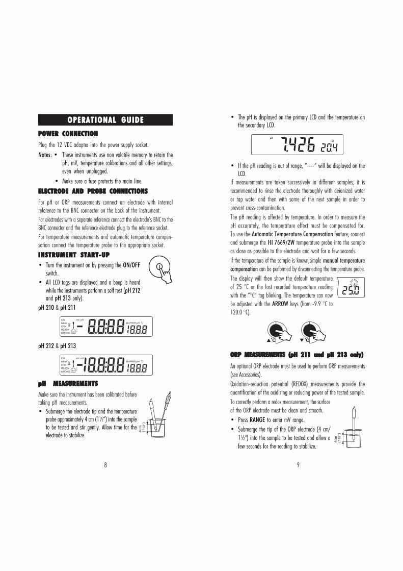
• The pH is displayed on the primary LCD and the temperature onthe secondary LCD.
• If the pH reading is out of range, “----” will be displayed on theLCD.
If measurements are taken successively in different samples, it isrecommended to rinse the electrode thoroughly with deionized wateror tap water and then with some of the next sample in order toprevent cross-contamination.The pH reading is affected by temperature. In order to measure thepH accurately, the temperature effect must be compensated for.To use the Automatic Temperature Compensation feature, connectand submerge the HI 7669/2W temperature probe into the sampleas close as possible to the electrode and wait for a few seconds.If the temperature of the sample is known,simple manual temperaturecompensation can be performed by disconnecting the temperature probe.The display will then show the default temperatureof 25 °C or the last recorded temperature readingwith the “°C” tag blinking. The temperature can nowbe adjusted with the ARROW keys (from -9.9 °C to120.0 °C).
ORP MEASUREMENTS (ORP MEASUREMENTS (ORP MEASUREMENTS (ORP MEASUREMENTS (ORP MEASUREMENTS (pppppH 211H 211H 211H 211H 211 and p and p and p and p and pH 213 H 213 H 213 H 213 H 213 onlyonlyonlyonlyonly)))))
An optional ORP electrode must be used to perform ORP measurements(see Accessories).Oxidation-reduction potential (REDOX) measurements provide thequantification of the oxidizing or reducing power of the tested sample.To correctly perform a redox measurement, the surfaceof the ORP electrode must be clean and smooth.• Press RANGE to enter mV range.• Submerge the tip of the ORP electrode (4 cm/
1½") into the sample to be tested and allow afew seconds for the reading to stabilize.
OPERATIONAL GUIDEOPERATIONAL GUIDEOPERATIONAL GUIDEOPERATIONAL GUIDEOPERATIONAL GUIDE
C C
pH
C
10 11
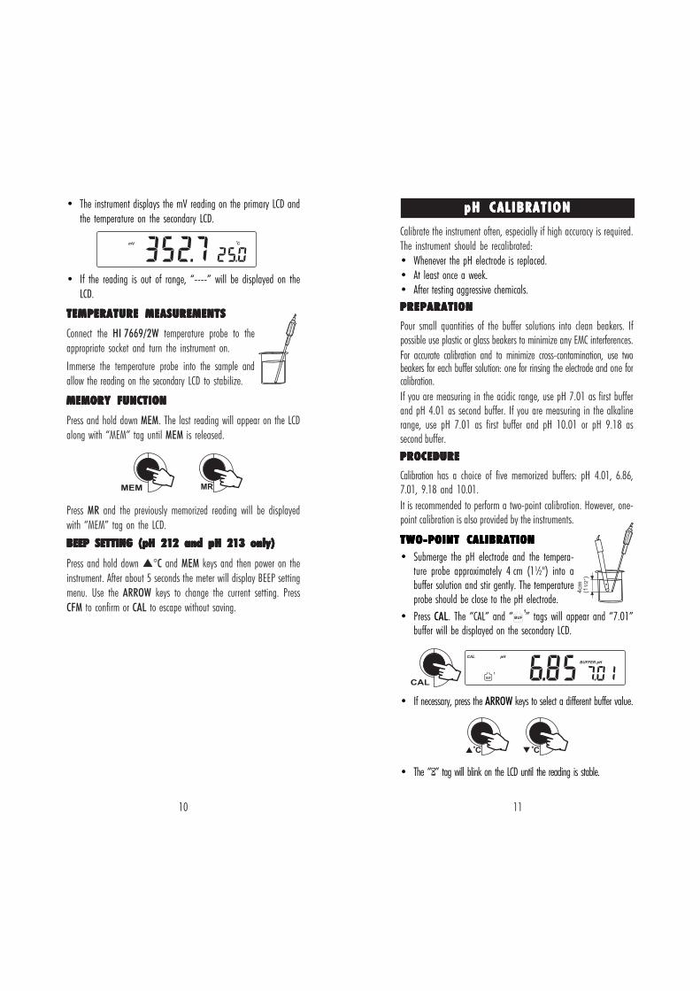
ppppp H CALIBRATIONH CALIBRATIONH CALIBRATIONH CALIBRATIONH CALIBRATION• The instrument displays the mV reading on the primary LCD andthe temperature on the secondary LCD.
• If the reading is out of range, “----” will be displayed on theLCD.
TEMPERATURE MEASUREMENTSTEMPERATURE MEASUREMENTSTEMPERATURE MEASUREMENTSTEMPERATURE MEASUREMENTSTEMPERATURE MEASUREMENTS
Connect the HI 7669/2W temperature probe to theappropriate socket and turn the instrument on.
Immerse the temperature probe into the sample andallow the reading on the secondary LCD to stabilize.
MEMORY FUNCTIONMEMORY FUNCTIONMEMORY FUNCTIONMEMORY FUNCTIONMEMORY FUNCTION
Press and hold down MEM. The last reading will appear on the LCDalong with “MEM” tag until MEM is released.
Press MR and the previously memorized reading will be displayedwith “MEM” tag on the LCD.
BEEP SETTINGBEEP SETTINGBEEP SETTINGBEEP SETTINGBEEP SETTING (((((pppppH 212 H 212 H 212 H 212 H 212 andandandandand pppppH 213 H 213 H 213 H 213 H 213 onlyonlyonlyonlyonly)))))
Press and hold down °C and MEM keys and then power on theinstrument. After about 5 seconds the meter will display BEEP settingmenu. Use the ARROW keys to change the current setting. PressCFM to confirm or CAL to escape without saving.
MR
Calibrate the instrument often, especially if high accuracy is required.The instrument should be recalibrated:• Whenever the pH electrode is replaced.• At least once a week.• After testing aggressive chemicals.PREPARATIONPREPARATIONPREPARATIONPREPARATIONPREPARATION
Pour small quantities of the buffer solutions into clean beakers. Ifpossible use plastic or glass beakers to minimize any EMC interferences.For accurate calibration and to minimize cross-contamination, use twobeakers for each buffer solution: one for rinsing the electrode and one forcalibration.If you are measuring in the acidic range, use pH 7.01 as first bufferand pH 4.01 as second buffer. If you are measuring in the alkalinerange, use pH 7.01 as first buffer and pH 10.01 or pH 9.18 assecond buffer.
PROCEDUREPROCEDUREPROCEDUREPROCEDUREPROCEDURE
Calibration has a choice of five memorized buffers: pH 4.01, 6.86,7.01, 9.18 and 10.01.It is recommended to perform a two-point calibration. However, one-point calibration is also provided by the instruments.
TWO-POINT CALIBRATIONTWO-POINT CALIBRATIONTWO-POINT CALIBRATIONTWO-POINT CALIBRATIONTWO-POINT CALIBRATION• Submerge the pH electrode and the tempera-
ture probe approximately 4 cm (1½") into abuffer solution and stir gently. The temperatureprobe should be close to the pH electrode.
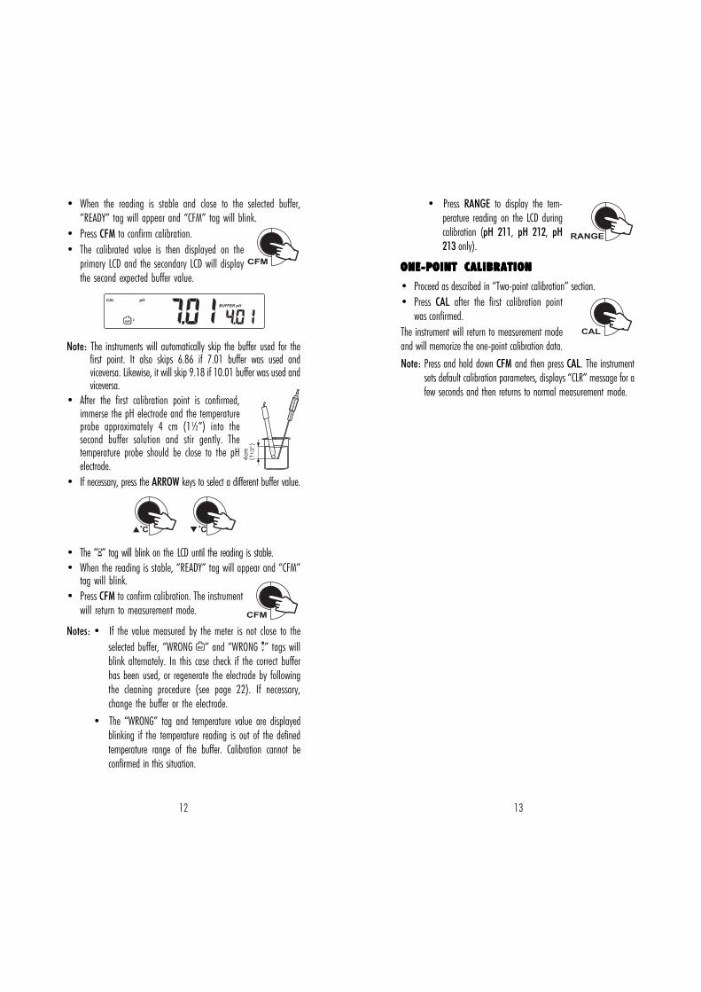
• Press CAL. The “CAL” and “ ” tags will appear and “7.01”buffer will be displayed on the secondary LCD.
• If necessary, press the ARROW keys to select a different buffer value.
• The “ ” tag will blink on the LCD until the reading is stable.
CAL
1
BUF
BUFFER pH
CAL
pH
mV C
MEM
C C
12 13
• When the reading is stable and close to the selected buffer,“READY” tag will appear and “CFM” tag will blink.
• Press CFM to confirm calibration.• The calibrated value is then displayed on the
primary LCD and the secondary LCD will displaythe second expected buffer value.
Note: The instruments will automatically skip the buffer used for thefirst point. It also skips 6.86 if 7.01 buffer was used andviceversa. Likewise, it will skip 9.18 if 10.01 buffer was used andviceversa.
• After the first calibration point is confirmed,immerse the pH electrode and the temperatureprobe approximately 4 cm (1½”) into thesecond buffer solution and stir gently. Thetemperature probe should be close to the pHelectrode.
• If necessary, press the ARROW keys to select a different buffer value.
• The “ ” tag will blink on the LCD until the reading is stable.• When the reading is stable, “READY” tag will appear and “CFM”
tag will blink.• Press CFM to confirm calibration. The instrument
will return to measurement mode.
Notes: • If the value measured by the meter is not close to theselected buffer, “WRONG ” and “WRONG ” tags willblink alternately. In this case check if the correct bufferhas been used, or regenerate the electrode by followingthe cleaning procedure (see page 22). If necessary,change the buffer or the electrode.
• The “WRONG” tag and temperature value are displayedblinking if the temperature reading is out of the definedtemperature range of the buffer. Calibration cannot beconfirmed in this situation.
C C
• Press RANGE to display the tem-perature reading on the LCD duringcalibration (pH 211, pH 212, pH213 only).
ONE-POINT CALIBRATIONONE-POINT CALIBRATIONONE-POINT CALIBRATIONONE-POINT CALIBRATIONONE-POINT CALIBRATION
• Proceed as described in “Two-point calibration” section.• Press CAL after the first calibration point
was confirmed.The instrument will return to measurement modeand will memorize the one-point calibration data.Note: Press and hold down CFM and then press CAL. The instrument
sets default calibration parameters, displays “CLR” message for afew seconds and then returns to normal measurement mode.
CFM
CFM
CAL
CAL
2BUF
pH
BUFFER pH
14 15
TEMPERATURE CALIBRATIONTEMPERATURE CALIBRATIONTEMPERATURE CALIBRATIONTEMPERATURE CALIBRATIONTEMPERATURE CALIBRATION((((( fo r te chn i ca l personne l on lyfo r te chn i ca l personne l on lyfo r te chn i ca l personne l on lyfo r te chn i ca l personne l on lyfo r te chn i ca l personne l on ly )))))
C C
C C
CFM
CAL
C
CAL
C
CFM
All the instruments are factory calibrated for temperature.Hanna’s temperature probes are interchangeable and no tempera-ture calibration is needed when they are replaced.If the temperature measurements are inaccurate, temperaturerecalibration should be performed.For an accurate recalibration, contact your dealer or the nearestHanna Customer Service Center, or follow the instructions bellow.• Prepare a vessel containing ice and water and another one
containing hot water (at a temperature of around 50 ºC). Placeinsulation material around the vessels to minimize temperaturechanges.
• Use a calibrated thermometer with a resolution of 0.1 ºC as areference thermometer.
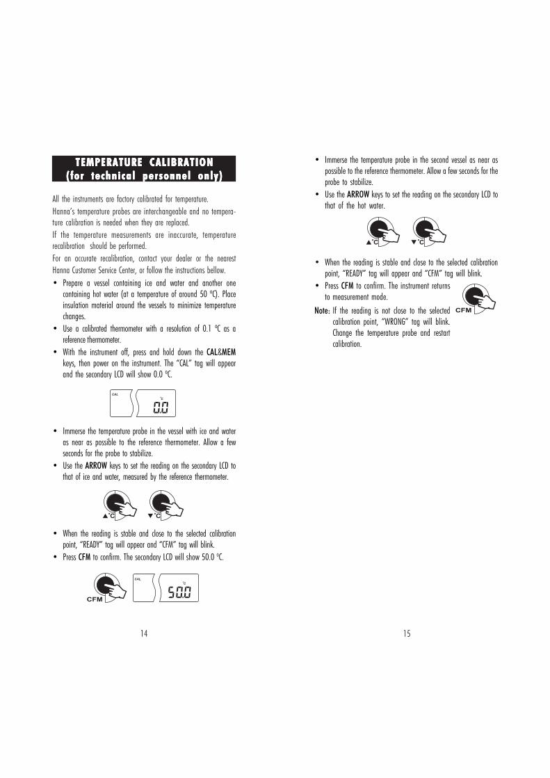
• With the instrument off, press and hold down the CAL&MEMkeys, then power on the instrument. The “CAL” tag will appearand the secondary LCD will show 0.0 ºC.
• Immerse the temperature probe in the vessel with ice and wateras near as possible to the reference thermometer. Allow a fewseconds for the probe to stabilize.
• Use the ARROW keys to set the reading on the secondary LCD tothat of ice and water, measured by the reference thermometer.
• When the reading is stable and close to the selected calibrationpoint, “READY” tag will appear and “CFM” tag will blink.
• Press CFM to confirm. The secondary LCD will show 50.0 ºC.
• Immerse the temperature probe in the second vessel as near aspossible to the reference thermometer. Allow a few seconds for theprobe to stabilize.
• Use the ARROW keys to set the reading on the secondary LCD tothat of the hot water.
• When the reading is stable and close to the selected calibrationpoint, “READY” tag will appear and “CFM” tag will blink.
• Press CFM to confirm. The instrument returnsto measurement mode.
Note: If the reading is not close to the selectedcalibration point, “WRONG” tag will blink.Change the temperature probe and restartcalibration.
16 17
Data transmission from the instrument to the PC can be done withthe HI 92000 Windows® compatible software (optional). HI 92000also offers graphing and on-line help feature.Data can be exported to the most popular spreadsheet programs forfurther analysis.To connect your instrument to a PC, use the optional Hanna HI 920010cable connector. Make sure that your instrument is switched off andplug one connector to the instrument RS232C socket and the other intothe serial port of your PC.Notes: • Other cables than HI 920010 may use a different
configuration. In this case communication between in-strument and PC may not be possible.
• If you are not using Hanna Instruments HI 92000software, please see the following instructions.
SETTING THE BAUD RATE AND THE COMMANDSETTING THE BAUD RATE AND THE COMMANDSETTING THE BAUD RATE AND THE COMMANDSETTING THE BAUD RATE AND THE COMMANDSETTING THE BAUD RATE AND THE COMMANDPREFIXPREFIXPREFIXPREFIXPREFIX• To set the instrument baud rate, press COMM
while in measurement mode. The primary LCDwill show the current baud rate.
• Use the ARROW keys to change the displayed value (150; 300;600; 1200; 2400 – factory setting; 4800; 9600).
• Press CFM to confirm. The primary LCD will show the currentcommand prefix (factory setting is 16).
• Use the ARROW keys to change the displayed value (between 0and 47).
• Press CFM to confirm. The meter returns tomeasurement mode.
Note: The command prefix must not be changed ifHI 92000 PC software is used.
PC INTERFACEPC INTERFACEPC INTERFACEPC INTERFACEPC INTERFACE(p(p(p(p(pH 212 & H 212 & H 212 & H 212 & H 212 & pppppH 213 H 213 H 213 H 213 H 213 onlyonlyonlyonlyonly )))))
mmmmmV CALIBRATION (V CALIBRATION (V CALIBRATION (V CALIBRATION (V CALIBRATION (ppppp H 213 H 213 H 213 H 213 H 213 onlyonlyonlyonlyonly )))))(for technical personnel only)
C C
CFM
COMM
All the instruments are factory calibrated for mV.Hanna’s ORP electrodes are interchangeable and no mV calibrationis needed when they are replaced.If the mV measurements are inaccurate, mV recalibration should beperformed.For an accurate recalibration, contact your dealer or the nearestHanna Customer Service Center, or follow the instructions below.A two or three-point calibration can be performed at 0.0 mV, 600.0mV and 1800.0 mV.• Attach to the BNC connector a mV simulator with an accuracy of
±0.1 mV.• With the instrument off, press and hold down the MR&CFM
keys, then power on the instrument. The “CAL” tag will appearand the secondary LCD will show 0.0 mV.
• Set 0.0 mV on the simulator.When the reading is stable and close to the selected calibrationpoint, “READY” tag will appear and “CFM” tag will blink.
• Press CFM to confirm. The secondary LCD will display 600 mV.• Set 600.0 mV on the simulator.
When the reading is stable and close to the selected calibrationpoint, “READY” tag will appear and “CFM” tag will blink.
• Press CFM to confirm. The secondary LCD will display 1800 mV.• Set 1800.0 mV on the simulator.
When the reading is stable and close to the selected calibrationpoint, “READY” tag will appear and “CFM” tag will blink.
• Press CFM to confirm. The instrument returns to measurementmode.
Notes: • If the reading is not close to the selected calibration point,“WRONG” tag will blink. Verify calibration condition orcontact your vendor if you can not calibrate.
• Press CAL in any moment of the calibration process. Theinstrument will return to measurement mode. If calibra-tion process is stopped after 600 mV is confirmed, the600 mV range is calibrated and calibration parametersare memorized.
18 19
SENDING COMMANDS FROM PCSENDING COMMANDS FROM PCSENDING COMMANDS FROM PCSENDING COMMANDS FROM PCSENDING COMMANDS FROM PC
It is also possible to remotely control the instrument with anyterminal program. Use HI 920010 cable to connect the instrument toa PC, start the terminal program and set the communication optionsas follows: 8, N, 1, no flow control.
COMMAND TYPESCOMMAND TYPESCOMMAND TYPESCOMMAND TYPESCOMMAND TYPESTo send a command to the instrument, follow the next scheme:
<DLE> <command> <CR>This line makes the computer send a Data Link Escape character, thecommand expressed as a 3-character sequence and a CR character.Note: All the terminal programs that support the ANSI escape
sequence, represent the DLE character by the string '^P' andthe CR character by the string '^M'.
SIMPLE COMMANDSSIMPLE COMMANDSSIMPLE COMMANDSSIMPLE COMMANDSSIMPLE COMMANDS
PHR sets the range to pHMVR sets the range to mV (pH 213 only)CAL is equivalent to pressing CALCFM is equivalent to pressing CFMUPC is equivalent to pressing the °C keyDWC is equivalent to pressing the °C keyMEM is equivalent to pressing MEMMRR is equivalent to pressing MRCOM is equivalent to pressing COMM
COMMANDS REQUIRING AN ANSWERCOMMANDS REQUIRING AN ANSWERCOMMANDS REQUIRING AN ANSWERCOMMANDS REQUIRING AN ANSWERCOMMANDS REQUIRING AN ANSWER
pH? Causes the instrument to send the pH reading ("Err 1" is sentif out of range). If the range is set to mV, "Err 6" is sent.
MV? Causes the instrument to send the mV reading ("Err 2" is sentif out of range). If the range is set to pH, "Err 6" is sent.
TM? Causes the instrument to send the temperature reading("Err 3" is sent if out of range).
Notes: • Either small or capital letters can be used.• The characters sent by the meter are always capital letters.• A “CAN” character (ASCII Code 24) is sent when the
instrument receives an unknown or a corrupted command.Note: Invalid commands will be ignored.
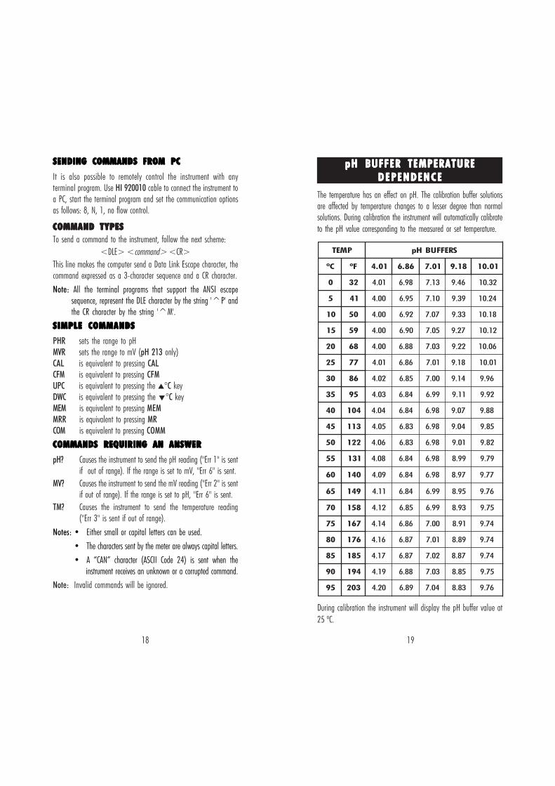
The temperature has an effect on pH. The calibration buffer solutionsare affected by temperature changes to a lesser degree than normalsolutions. During calibration the instrument will automatically calibrateto the pH value corresponding to the measured or set temperature.
During calibration the instrument will display the pH buffer value at25 ºC.
ppppp H BUFFER TEMPERATUREH BUFFER TEMPERATUREH BUFFER TEMPERATUREH BUFFER TEMPERATUREH BUFFER TEMPERATURED E P E N D E N C ED E P E N D E N C ED E P E N D E N C ED E P E N D E N C ED E P E N D E N C E
PMET SREFFUBHp
Cº Fº 10.4 68.6 10.7 81.9 10.01
0 23 10.4 89.6 31.7 64.9 23.01
5 14 00.4 59.6 01.7 93.9 42.01
01 05 00.4 29.6 70.7 33.9 81.01
51 95 00.4 09.6 50.7 72.9 21.01
02 86 00.4 88.6 30.7 22.9 60.01
52 77 10.4 68.6 10.7 81.9 10.01
03 68 20.4 58.6 00.7 41.9 69.9
53 59 30.4 48.6 99.6 11.9 29.9
04 401 40.4 48.6 89.6 70.9 88.9
54 311 50.4 38.6 89.6 40.9 58.9
05 221 60.4 38.6 89.6 10.9 28.9
55 131 80.4 48.6 89.6 99.8 97.9
06 041 90.4 48.6 89.6 79.8 77.9
56 941 11.4 48.6 99.6 59.8 67.9
07 851 21.4 58.6 99.6 39.8 57.9
57 761 41.4 68.6 00.7 19.8 47.9
08 671 61.4 78.6 10.7 98.8 47.9
58 581 71.4 78.6 20.7 78.8 47.9
09 491 91.4 88.6 30.7 58.8 57.9
59 302 02.4 98.6 40.7 38.8 67.9
20 21
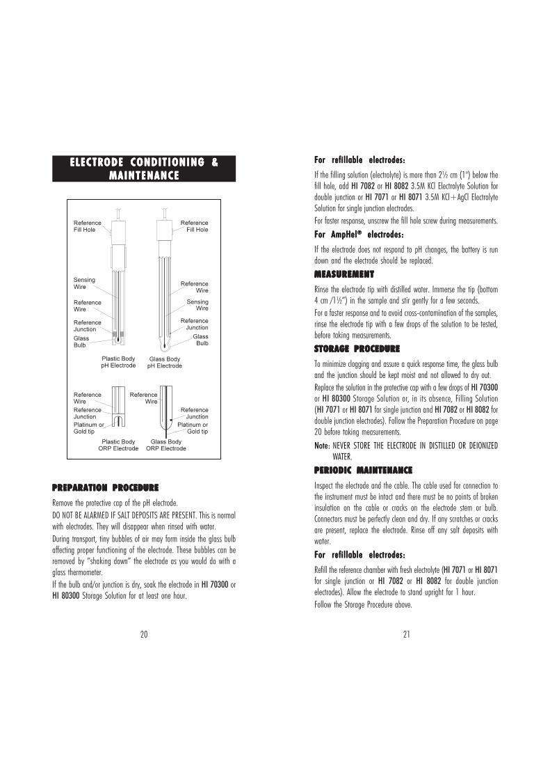
ELECTRODE CONDITIONING &ELECTRODE CONDITIONING &ELECTRODE CONDITIONING &ELECTRODE CONDITIONING &ELECTRODE CONDITIONING &MAINTENANCEMAINTENANCEMAINTENANCEMAINTENANCEMAINTENANCE
For refillable electrodes:For refillable electrodes:For refillable electrodes:For refillable electrodes:For refillable electrodes:
If the filling solution (electrolyte) is more than 2½ cm (1") below thefill hole, add HI 7082 or HI 8082 3.5M KCl Electrolyte Solution fordouble junction or HI 7071 or HI 8071 3.5M KCl+AgCl ElectrolyteSolution for single junction electrodes.For faster response, unscrew the fill hole screw during measurements.
For AmpHelFor AmpHelFor AmpHelFor AmpHelFor AmpHel®®®®® electrodes: electrodes: electrodes: electrodes: electrodes:
If the electrode does not respond to pH changes, the battery is rundown and the electrode should be replaced.
MEASUREMENTMEASUREMENTMEASUREMENTMEASUREMENTMEASUREMENT
Rinse the electrode tip with distilled water. Immerse the tip (bottom4 cm /1½”) in the sample and stir gently for a few seconds.For a faster response and to avoid cross-contamination of the samples,rinse the electrode tip with a few drops of the solution to be tested,before taking measurements.
STORAGE STORAGE STORAGE STORAGE STORAGE PROCEDUREPROCEDUREPROCEDUREPROCEDUREPROCEDURE
To minimize clogging and assure a quick response time, the glass bulband the junction should be kept moist and not allowed to dry out.Replace the solution in the protective cap with a few drops of HI 70300or HI 80300 Storage Solution or, in its absence, Filling Solution(HI 7071 or HI 8071 for single junction and HI 7082 or HI 8082 fordouble junction electrodes). Follow the Preparation Procedure on page20 before taking measurements.Note: NEVER STORE THE ELECTRODE IN DISTILLED OR DEIONIZED
WATER.PERIODIC MAINTENANCEPERIODIC MAINTENANCEPERIODIC MAINTENANCEPERIODIC MAINTENANCEPERIODIC MAINTENANCE
Inspect the electrode and the cable. The cable used for connection tothe instrument must be intact and there must be no points of brokeninsulation on the cable or cracks on the electrode stem or bulb.Connectors must be perfectly clean and dry. If any scratches or cracksare present, replace the electrode. Rinse off any salt deposits withwater.For refillable electrodes:For refillable electrodes:For refillable electrodes:For refillable electrodes:For refillable electrodes:
Refill the reference chamber with fresh electrolyte (HI 7071 or HI 8071for single junction or HI 7082 or HI 8082 for double junctionelectrodes). Allow the electrode to stand upright for 1 hour.Follow the Storage Procedure above.
PREPARATION PROCEDUREPREPARATION PROCEDUREPREPARATION PROCEDUREPREPARATION PROCEDUREPREPARATION PROCEDURE
Remove the protective cap of the pH electrode.DO NOT BE ALARMED IF SALT DEPOSITS ARE PRESENT. This is normalwith electrodes. They will disappear when rinsed with water.During transport, tiny bubbles of air may form inside the glass bulbaffecting proper functioning of the electrode. These bubbles can beremoved by “shaking down” the electrode as you would do with aglass thermometer.If the bulb and/or junction is dry, soak the electrode in HI 70300 orHI 80300 Storage Solution for at least one hour.
22 23
CLEANING PROCEDURECLEANING PROCEDURECLEANING PROCEDURECLEANING PROCEDURECLEANING PROCEDURE
• General Soak in Hanna HI 7061 or HI 8061 GeneralCleaning Solution for approximately ½ hour.
• Protein Soak in Hanna HI 7073 or HI 8073 ProteinCleaning Solution for 15 minutes.
• Inorganic Soak in Hanna HI 7074 Inorganic CleaningSolution for 15 minutes.
• Oil/grease Rinse with Hanna HI 7077 or HI 8077 Oil andFat Cleaning Solution.
IMPORTANT: After performing any of the cleaning procedures, rinsethe electrode thoroughly with distilled water, refill the referencechamber with fresh electrolyte (not necessary for gel-filled electrodes)and soak the electrode in HI 70300 or HI 80300 Storage Solution forat least 1 hour before taking measurements.
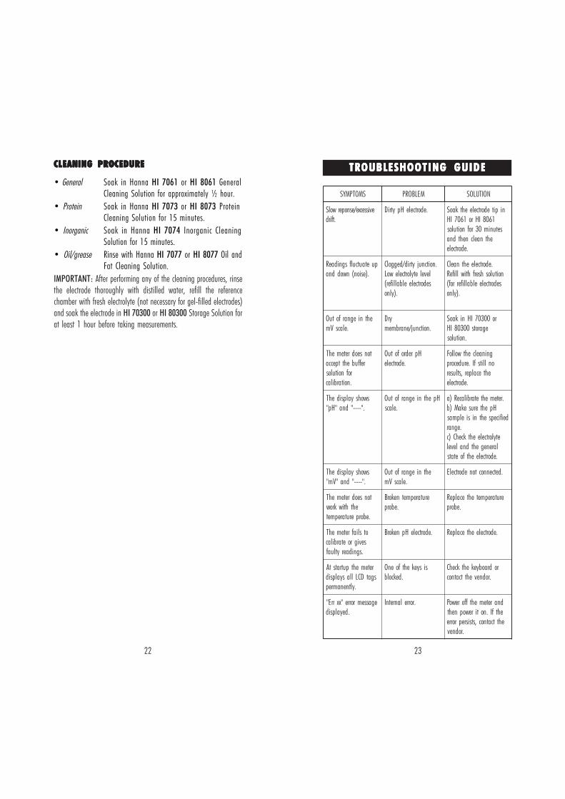
TROUBLESHOOTING GUIDETROUBLESHOOTING GUIDETROUBLESHOOTING GUIDETROUBLESHOOTING GUIDETROUBLESHOOTING GUIDE
SMOTPMYS MELBORP NOITULOS
evissecxe/esnoperwolS.tfird
.edortceleHpytriD nipitedortceleehtkaoS1608IHro1607IH
setunim03rofnoitulosehtnaelcnehtdna
.edortcele
puetautculfsgnidaeR.)esion(nwoddna
.noitcnujytrid/deggolCleveletylortcelewoLsedortceleelballifer(
.)ylno
.edortceleehtnaelCnoituloshserfhtiwllifeRsedortceleelballiferrof(
.)ylno
ehtniegnarfotuO.elacsVm
yrD.noitcnuj/enarbmem
ro00307IHnikaoSegarots00308IH
.noitulos
tonseodretemehTreffubehttpecca
rofnoitulos.noitarbilac
HpredrofotuO.edortcele
gninaelcehtwolloFonllitsfI.erudecorp
ehtecalper,stluser.edortcele
swohsyalpsidehT."----"dna"Hp"
HpehtniegnarfotuO.elacs
.retemehtetarbilaceR)aHpehterusekaM)b
deificepsehtnisielpmas.egnar
etylortceleehtkcehC)clarenegehtdnalevel.edortceleehtfoetats
swohsyalpsidehT."----"dna"Vm"
ehtniegnarfotuO.elacsVm
.detcennoctonedortcelE
tonseodretemehTehthtiwkrow
.eborperutarepmet
erutarepmetnekorB.eborp
erutarepmetehtecalpeR.eborp
otsliafretemehTsevigroetarbilac
.sgnidaerytluaf
.edortceleHpnekorB .edortceleehtecalpeR
retemehtputratstAsgatDCLllasyalpsid
.yltnenamrep
sisyekehtfoenO.dekcolb
rodraobyekehtkcehC.rodnevehttcatnoc
egassemrorre"xxrrE".deyalpsid
.rorrelanretnI dnaretemehtfforewoPehtfI.notirewopnehtehttcatnoc,stsisreprorre
.rodnev
24 25
ACCESSORIESACCESSORIESACCESSORIESACCESSORIESACCESSORIES
pH BUFFER SOLUTIONS
HI 70004P pH 4.01 Buffer Sachets, 20 mL, 25 pcsHI 70007P pH 7.01 Buffer Sachets, 20 mL, 25 pcsHI 70010P pH 10.01 Buffer Sachets, 20 mL, 25 pcsHI 7004L pH 4.01 Buffer Solution, 500 mL bottleHI 7006L pH 6.86 Buffer Solution, 500 mL bottleHI 7007L pH 7.01 Buffer Solution, 500 mL bottleHI 7009L pH 9.18 Buffer Solution, 500 mL bottleHI 7010L pH 10.01 Buffer Solution, 500 mL bottleHI 8004L pH 4.01 Buffer Sol. in FDA approved bottle, 500 mLHI 8006L pH 6.86 Buffer Sol. in FDA approved bottle, 500 mLHI 8007L pH 7.01 Buffer Sol. in FDA approved bottle, 500 mLHI 8009L pH 9.18 Buffer Sol. in FDA approved bottle, 500 mLHI 8010L pH 10.01 Buffer Sol. in FDA approved bottle, 500 mL
ELECTRODE STORAGE SOLUTIONS
HI 70300L Storage Solution, 460 mL bottleHI 80300L Storage Solution in FDA approved bottle, 460 mL
ELECTRODE CLEANING SOLUTIONS
HI 70000P Electrode Rinse Sachets, 20 mL, 25 pcsHI 7061L General Cleaning Solution, 460 mL bottleHI 7073L Protein Cleaning Solution, 460 mL bottleHI 7074L Inorganic Cleaning Solution, 460 mL bottleHI 7077L Oil & Fat Cleaning Solution, 460 mL bottleHI 8061L General Cleaning Sol. in FDA approved bottle, 460 mLHI 8073L Protein Cleaning Solution in FDA approved bottle, 460 mLHI 8077L Oil & Fat Cleaning Sol. in FDA approved bottle, 460 mL
ELECTRODE REFILL ELECTROLYTE SOLUTIONS
HI 7071 3.5M KCl+AgCl Electrolyte, 4x50 mL, for single junctionelectrodes
HI 7072 1M KNO3 Electrolyte, 4x50 mLHI 7082 3.5M KCl Electrolyte, 4x50 mL, for double junction
electrodesHI 8071 3.5M KCl+AgCl Electrolyte in FDA approved bottle,
4x50 mL, for single junction electrodesHI 8072 1M KNO3 Electrolyte in FDA approved bottle, 4x50 mLHI 8082 3.5M KCl Electrolyte in FDA approved bottle, 4x50 mL
Typical Electrode LifeAmbient Temperature 1- 3 years90 °C Less than 4 months120 °C Less than 1 month
Alkaline ErrorHigh concentrations of sodium ions interfere with readings in alkalinesolutions. The pH at which the interference starts to be significantdepends upon the composition of the glass. This interfe-rence is calledalkaline error and causes the pH to be underestimated. Hanna’s glassformulations have the indicated characteristics.
1.0 Mol L-1 Na+
0.1 Mol L-1 Na+
Sodium Ion Correction for Glass at 20-25 °CConcentration pH Error
13.0013.5014.0012.5013.0013.5014.00
0.100.140.200.100.180.290.40
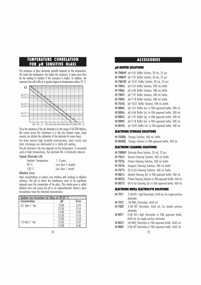
The resistance of glass electrodes partially depends on the temperature.The lower the temperature, the higher the resistance. It takes more timefor the reading to stabilize if the resistance is higher. In addition, theresponse time will suffer to a greater degree at temperatures below 25 °C.
Since the resistance of the pH electrode is in the range of 50-200 Mohms,the current across the membrane is in the pico Ampere range. Largecurrents can disturb the calibration of the electrode for many hours.For these reasons high humidity environments, short circuits andstatic discharges are detrimental to a stable pH reading.The pH electrode’s life also depends on the temperature. If constantlyused at high temperatures, the electrode life is drastically reduced.
TEMPERATURE CORRELATIONTEMPERATURE CORRELATIONTEMPERATURE CORRELATIONTEMPERATURE CORRELATIONTEMPERATURE CORRELATIONFOR FOR FOR FOR FOR ppppp H SENSITIVE GLASSH SENSITIVE GLASSH SENSITIVE GLASSH SENSITIVE GLASSH SENSITIVE GLASS
26 27
HI 1330BGlass-body, semimicro, single junction, refillable, combination pHelectrode. Use: laboratory, vials.
HI 1331BGlass-body, semimicro, single junction, refillable, combination pHelectrode. Use: flasks.
HI 1230BPlastic-body (Ultem®), double junction, gel-filled, combination pHelectrode. Use: general, field.
HI 2031BGlass-body, semimicro, conic, refillable, combination pH electrode. Use:semisolid products.
HI 1332BPlastic-body (Ultem®), double junction, refillable, combination pHelectrode. Use: general purpose.
120 mm4.7"
5mm0.2"
5mm DIA0.2"
"S" VERSION
HI 1330
120 mm4.7"
12 mm0.5"
"S" VERSION
HI 1230
75 mm2.95"
6 mm0.25"
"S" VERSION
HI 2031
120 mm4.7"
12 mm0.5"
"S" VERSION
HI 1332
210 mm8.25"
8 mm0.3"
7.5mm DIA0.29"
"S" VERSION
HI 1331
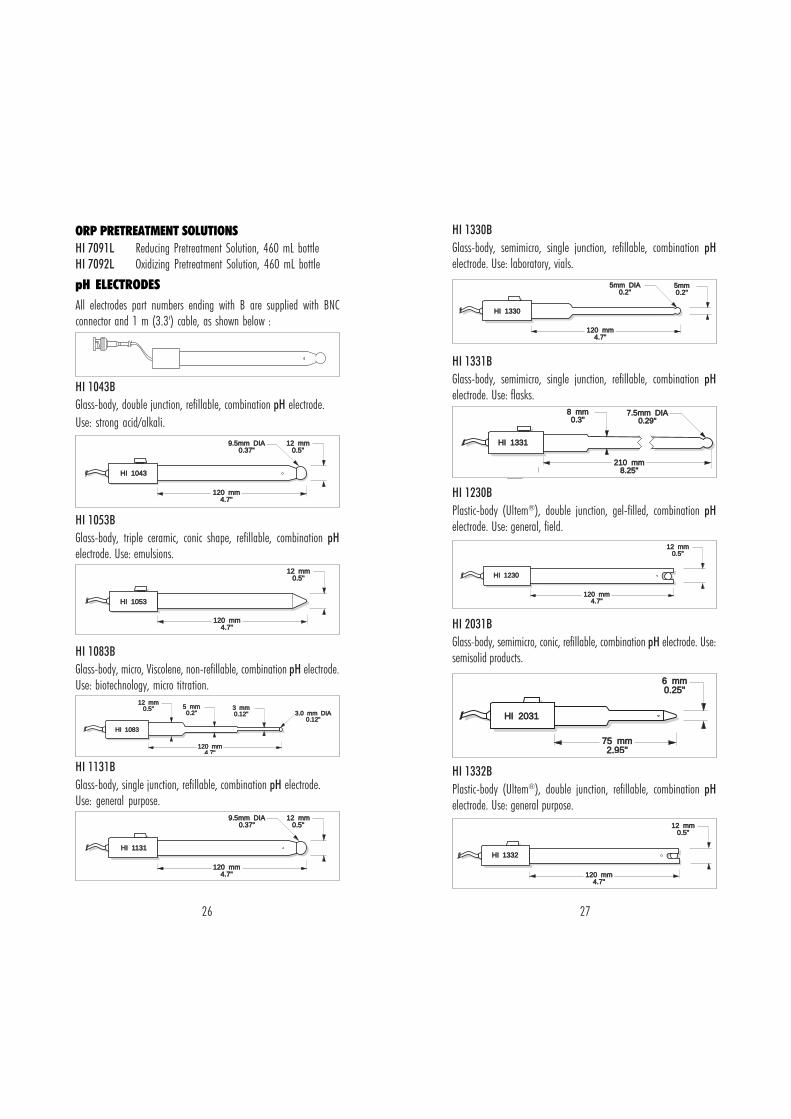
ORP PRETREATMENT SOLUTIONSHI 7091L Reducing Pretreatment Solution, 460 mL bottleHI 7092L Oxidizing Pretreatment Solution, 460 mL bottle
pH ELECTRODESAll electrodes part numbers ending with B are supplied with BNCconnector and 1 m (3.3') cable, as shown below :
HI 1043BGlass-body, double junction, refillable, combination pH electrode.Use: strong acid/alkali.
HI 1053BGlass-body, triple ceramic, conic shape, refillable, combination pHelectrode. Use: emulsions.
HI 1083BGlass-body, micro, Viscolene, non-refillable, combination pH electrode.Use: biotechnology, micro titration.
HI 1131BGlass-body, single junction, refillable, combination pH electrode.Use: general purpose.
120 mm4.7"
12 mm0.5"
9.5mm DIA0.37"
"S" VERSION
HI 1043
120 mm4.7"
12 mm0.5"
"S" VERSION
HI 1053
120 mm4.7"
12 mm0.5" 5 mm
0.2"3 mm0.12" 3.0 mm DIA
0.12"
HI 1083
120 mm4.7"
12 mm0.5"
9.5mm DIA0.37"
"S" VERSION
HI 1131
28 29
Kynar® is registered Trademark of "Pennwalt Corp."Ultem® is registered Trademark of "General Electric Co."
HI 1413BGlass-body, single junction, flat tip, Viscolene, non-refillable, combinationpH electrode. Use: surface measurement.
ORP ELECTRODESHI 3131BGlass-body, refillable, combination platinum ORP electrode.Use: titration.
HI 3230BPlastic-body (Ultem®), gel-filled, combination platinum ORP elec-trode. Use: general purpose.
HI 4430BPlastic-body (Ultem®), gel-filled, combination gold ORP electrode.Use: general purpose.
Consult the Hanna General Catalog for more electrodes with screw-type or BNC connectors.
110 mm4.3"
12 mm0.5"
HI 1413
150 mm5.9"
12 mm0.5"
"S" VERSION
HI 3131
120 mm4.7"
12 mm0.5"
HI 3230
"S" VERSION
120 mm4.7"
12 mm0.5"
HI 4430
"S" VERSION
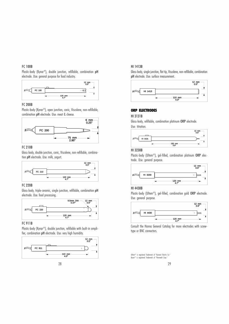
FC 100BPlastic-body (Kynar®), double junction, refillable, combination pHelectrode. Use: general purpose for food industry.
FC 200BPlastic-body (Kynar®), open junction, conic, Viscolene, non-refillable,combination pH electrode. Use: meat & cheese.
FC 210BGlass-body, double junction, conic, Viscolene, non-refillable, combina-tion pH electrode. Use: milk, yogurt.
FC 220BGlass-body, triple-ceramic, single junction, refillable, combination pHelectrode. Use: food processing.
FC 911BPlastic-body (Kynar®), double junction, refillable with built-in ampli-fier, combination pH electrode. Use: very high humidity.
120 mm4.7"
12 mm0.5"
FC 100
75 mm2.95"
6 mm0.25"
FC 200
120 mm4.7"
12 mm0.5"
FC 210
120 mm4.7"
12 mm0.5"
9.5mm DIA0.37"
FC 220
110 mm4.3"
12 mm0.5"
FC 911
30 31
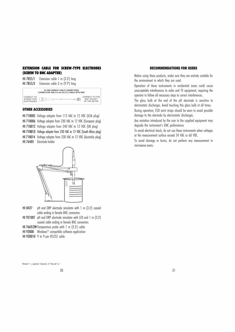
EXTENSION CABLE FOR SCREW-TYPE ELECTRODES(SCREW TO BNC ADAPTER)HI 7855/1 Extension cable 1 m (3.3') longHI 7855/3 Extension cable 3 m (9.9') long
OTHER ACCESSORIES
HI 710005 Voltage adapter from 115 VAC to 12 VDC (USA plug)HI 710006 Voltage adapter from 230 VAC to 12 VDC (European plug)HI 710012 Voltage adapter from 240 VAC to 12 VDC (UK plug)HI 710013 Voltage adapter from 230 VAC to 12 VDC (South Africa plug)HI 710014 Voltage adapter from 230 VAC to 12 VDC (Australia plug)HI 76405 Electrode holder
HI 8427 pH and ORP electrode simulator with 1 m (3.3') coaxialcable ending in female BNC connectors
HI 931001 pH and ORP electrode simulator with LCD and 1 m (3.3')coaxial cable ending in female BNC connectors
HI 7669/2WTemperature probe with 1 m (3.3') cableHI 92000 Windows® compatible software applicationHI 920010 9 to 9-pin RS232 cable
CONNECT TOSCREW TYPEELECTRODES
CONNECT TO THEBNC SOCKET
OF THE METER
HI 7855 SERIES CABLE CONNECTORSCONNECTOR AND 3.0 mm (0.12") CABLE WITH BNC
Windows® is registered Trademark of "Microsoft Co."
RECOMMENDATIONS FOR USERS
Before using these products, make sure they are entirely suitable forthe environment in which they are used.Operation of these instruments in residential areas could causeunacceptable interferences to radio and TV equipment, requiring theoperator to follow all necessary steps to correct interferences.The glass bulb at the end of the pH electrode is sensitive toelectrostatic discharges. Avoid touching this glass bulb at all times.During operation, ESD wrist straps should be worn to avoid possibledamage to the electrode by electrostatic discharges.Any variation introduced by the user to the supplied equipment maydegrade the instrument’s EMC performance.To avoid electrical shock, do not use these instruments when voltagesat the measurement surface exceed 24 VAC or 60 VDC.To avoid damage or burns, do not perform any measurement inmicrowave ovens.