pg_2102-2161_clinkercoolers_text.pdf
TRANSCRIPT

"Holderbank" Cement Seminar 2000 ===
Process Technology II - Kiln Systems
Clinker Coolers
U. Gasser / D. Brassel
PT97/14232/E (Revision 1, February 1999)
1 . INTRODUCTION 1 1
6
2. GENERAL CONSIDERATIONS 116
2.1 Heat Flow in a Kiln System 116
2.2 Definitions 118
2.3 Calculations 120
3. GRATE COOLERS 122
3.1 The Reciprocating Grate Cooler 122
3.1.1 Principle 122
3.1.2 History 124
3.1 .3 Conventional Grate Coolers (1 980's) 126
3.1.4 Typical Grate Cooler Problems .... 128
3.1.5 Modern Grate Coolers (1990's) 130
3.1.6 Design Highlights of Modern Grate Coolers 132
3.1.7 Clinker Crushers 141
3.1.8 Cooler control 146
3.1.9 Cooler Dedusting 148
3.1.10 Developments 150
3.2 The Cross Bar Cooler 152
3.2.1 Principle 152
3.2.2 Main features 152
3.2.3 Strengths and Weaknesses 154
3.3 The Travelling Grate Cooler 156
3.3.1 Principle 156
3.3.2 Strengths and Weaknesses 158
4. ROTATING COOLERS 160
4.1 The Rotary Cooler or Tube Cooler 160
4.1.1 Principle 160
4.1.2 Design Features. 160
4.1.3 Cooling performance 162
4.1.4 Strengths / Weaknesses 162
4.2 The Planetary Cooler 163
© Holderbank Management & Consulting, 2000 Page 1 1
3

"Holderbank" Cement Seminar 2000
Process Technology II - Kiln Systems
4.2.1 Principle 163
4.2.2 Historical 164
4.2.3 Design features 165
4.2.4 Internal heat transfer equipment (see Fig. 26) 165
5. VERTICAL COOLERS 167
5.1 The Gravity Cooler (G - Cooler) 167
5.2 The Shaft Cooler 167
Page 114 © Holderbank Management & Consulting, 2000

"Holderbank" Cement Seminar 2000 ^^Process Technology II - Kiln Systems
SUMMARY
Clinker coolers have two tasks to fulfil:
Recuperate as much heat as possible from the hot clinker by heating up the air used
for combustion
Cool the clinker from 1 400°C to temperatures adequate for the subsequent process
equipment, normally to 100 - 200°C.
There are mainly two different types of clinker coolers in operation with the following
features:
Grate coolers
Crossflow heat exchange through horizontal clinker bed with cold air from below.
Cooling airflow exceeding combustion air requirement allows low clinker temperatures,
but necessitates excess (waste) air dedusting.
Modern cooler technology with sophisticated plates and forced aeration systems allow
combustion air temperatures exceeding 1 000°C.
Trend to wider and fewer grates, less cooling air and fixed inlets
Largest units: 10'000t/d
Travelling grate (Recupol): last unit built around 1980
Rotating coolers
Rotary tube coolers with separate drive or planetary cooler attached to kiln shell
Quasi counter-current flow heat exchange
Cooling air determined by combustion air, no waste air
Heat exchange (recuperation) determined by condition of internal heat transfer
equipment
Limited unit size, up to 3000 t/d
Planetary cooler not suitable for precalciner technology
Practically no new installation built anymore
© Holderbank Management & Consulting, 2000 Page 1 1
5

•'Holderbank" Cement Seminar 2000 ^^Process Technology II - Kiln Systems
1. INTRODUCTION
The clinker cooler is a vital part of the kiln system and has a decisive influence on the
performance of the plant. Three key indicators characterize a good cooler:
Maximum heat recuperation
Minimum cooling air flow
Unrestricted availability
There have been periodic changes in trends during the past decades. Grate coolers were
first introduced by Fuller Company (USA) around 1 930. While its design was continuously
being optimized, the grate cooler became the predominant type in the 1950's. In the late
1 960's, the planetary cooler gained popularity which reached its peak in the 1 970's, mainly
due to its simplicity. Larger unit capacities with precalciner technology made the grate cooler
the preferred solution again. A wave of grate cooler reengineering starting in the mid 1980's
has generated a much improved grate cooler technology as well as a new situation on the
suppliers' side. New problems were experienced and have been or are being solved.
Since cement plants have life cycles of 40 years and more, numerous units of each cooler
type, planetary, rotary or grate cooler of old or new designs, will remain in operation for
many more years.
2. GENERAL CONSIDERATIONS
The clinker cooler has the following tasks to fulfil:
Process internal heat recuperation by heat transfer from clinker to combustion air
Reduce clinker temperature to facilitate clinker handling and storage
Provide maximum cooling velocity to avoid unfavorable clinker phases and crystal size
2.1 Heat Flow in a Kiln System
The importance of the cooler as a heat recuperator can be well demonstrated with a heat
flow (Sanki) diagram.
Page 116 © Holderbank Management & Consulting, 2000

"Holderbank" Cement Seminar 2000
Process Technology II - Kiln Systems

''Holderbank" Cement Seminar 2000Process Technology II - Kiln Systems
2.2 Definitions
As for other components of the kiln system, specific figures for clinker coolers refer to
1 kg of clinker. This eliminates the influence of plant size and allows direct comparison
of clinker coolers of different types and sizes.
Cooling air is the air which passes the clinker thus being heated up while cooling the
clinker. It corresponds approximately to the combustion air requirement, only grate
coolers allow additional air for better cooling.
Primary air is the air which is required for proper functioning of the burner. Ambient air
insufflated by a separate small fan plus the air from a pneumatic transport system,
amounting from < 1 0% up to > 30% of the air required to combust that fuel. Someprecalciner burners are equipped with primary air fans (for cooling) as well.
Secondary air is the hot air entering the rotary kiln via clinker cooler. Its flow is
determined by the combustion of the burning zone fuel. While cooling the clinker, it
reaches temperatures of 600 to over 1000°C, depending on type and condition of the
cooler.
Tertiary air is that part of the combustion air which is required for combusting the
precalciner fuel. It is extracted from kiln hood or cooler roof, and then taken along a duct
(=tertiary air duct) parallel to the kiln to the precalciner. It reaches temperatures near or
equal to the level of the secondary air.
Middle air (grate cooler only) is extracted from the cooler roof if drying of process
materials requires a temperature level which is higher than the waste air. If the quantity
is small, up to 450°C can be expected at normal cooler operation.
Waste air (grate cooler only) is also called cooler exit air or cooler excess air. The total
cooling airflow from the fans is normally higher than the flow required for combustion
(=tertiary + secondary air). The extra air, which has normally a temperature of 200 to
300°C, must be vented to ambient via a dedusting system.
False air is cold air entering the system via kiln outlet seal, burner opening, casing or
clinker discharge. It either dilutes secondary air thus reducing recuperated heat or adds
load to the waste air system of grate coolers.
Specific air volumes are airflows per kg of clinker (m3/kg cli, Nm3
/kg cli). Independent
of the kiln size, airflows of cooler systems can be directly compared.
Specific loads express the relation of clinker production to a characteristic dimension of
the cooler (t/d m, t/d m2, t/d m3
). Exact definitions vary with cooler type.
Radiation losses from the cooler casing/shell are particularly important for planetary
coolers, where they actively support the cooling of the clinker.
Efficiency expresses the quality of heat transfer from clinker to the air which is used for
combustion in the burning zone and precalciner firing.
Remark: Since the heat recuperated is proportional to hot air used for combustion and
temperature, an efficiency figure is only meaningful if it is related to a heat
consumption figure (resp. a combustion airflow).
Page 118 © Holderbank Management & Consulting, 2000

"Holderbank" Cement Seminar 2000
Process Technology II - Kiln Systems
'HOLDERBANK"
Figure 3 Clinker coolers - Definitions
Grate Cooler
AActive grate area (m2 )
Grate length L (m)Grate width W (m)
Grate inclination e (o )
Number of grates n (")Installed fan power P
F(kW)
Installed drive power Pn (kW)
Tertiary air
False air.
Secondary air
Middle air
t
Primary air
TO-
Grate speed -
Hot clinker >
Recuperation zone'
Waste
t
air
Aftercooling zone
a:
? ? tp tp tp
Cooling air
CooledClinker
Plonetory Cooler
Tube length
Tube diameter
Elbow cross section
Number of tubes
Cylindrical surface
elbow
't
(m)(m)(m2 )
(-)(m2
)
Secondary air
Hot clinker
CooledTube Cooler
Tube length L (m)D (m)G (o )
PD
(kW)
Clinker
Tube diameter Tertiary air -«
"\Slope
Installed drive power1
h> Radiation
>Q— Primary oir *
¥ — False air y1—
^
H
Hot clinker]d
soled
inker
J
C<
CI
© Holderbank Management & Consulting, 2000 Page 119

"Holderbank" Cement Seminar 2000
Process Technology II - Kiln Systems
"HOLDERBANK'
2.3 Calculations
The calculations below are examples of heat balance investigations:
• Heat in hot clinker Qen :
Qcn = rnci* cpci* (tc ii-
1
ref) Example with mc,,=1 kg/h:
tcii=1400°C:
Qdi = 1 kg/h * 1.090 kJ/kg°C * (1400°C-20°C) = 1504 kJ/h
• Heat in hot air Q„ir
:
Uair = » air Cpajr (ta j r- t ref)
Example with V air = 1Nm3/h:
tair =1066°C:
Qai.= 1 Nm3
/h * 1.421 kJ/Nm3oC * (1066°C-20°C) = 1486 kJ/h
• Radiation loss Qra*:
Q rad =CR *e*A{(t/ioo)4
-
(to/100)4}
Grate cooler
Q rad = 20 kJ/kg cli (from experience)
Cooler efficiency Ti COoier „ _ ** combustion air _ -| Z—t '°ss
i cooler ~ p. O** clinker from kiln ^* clinker from kiln
The secondary (+ tertiary) air requirements are dictated by the amount of fuel fed to the
burners. Per this definition, the efficiency of a cooler is getting better with increasing kiln
heat consumption. It is thus obvious that a cooler efficiency figure is only meaningful if the
corresponding heat consumption (or airflow) is indicated.
Example: production
heat consumption
secondary and tertiary
air temperatures
Primary air main burner
PC fuel ratio
5000 t/d
3000 kJ/kg cli
1066°C
10%
60%
False air and excess air neglected (not realistic!)
Q comb air-
" Comb air
t comb air
« comb air
= 3000 MJ/kg cli* 0.26 Nm3
/MJ * 5000/24*13kg/h * (1-0.4*0.1)
= 156'000Nm3/h
= 1066°C -> q combustion air = 1 -421 kJ/Nm3° * (1066-20)° = 1486 kJ/Nm3
= V comb air* q cornb air = 1 486*1 56'000 kJ/h = 231 '81 6 GJ/h
** clinker-
m clinker
t clinker from kiln
U clinker
Efficiency n
= 5000 t/d /24 h/d *13kg/t = 208'333 kg/h
= 1400°C -> q dnker from kim = 1-09 kJ/kg° * (1400-20)° = 1504 kJ/kg
= 208'333 * 1504 kJ/kg = 313'333 GJ/h
= 231 '81 6 / 31 3'333 * 1 00% = 74.0%
Page 120 © Holderbank Management & Consulting, 2000

"Holderbank" Cement Seminar 2000
Process Technology 11 - Kiln Systems
!Mi.]=H:M?rTaa
Figure 4 Clinker cooler typical data (4-stage SP Kiln, 2'000 t/d)
ev. to precalciner
1 kg cli.H00°C
(*T) mbar : 60
(*|) mbar : |100
3250kJ/kg cii
"G-n\ 0,85Nm 3/kg cli
1000°C(g)
5590A
a:
? ?
5075
40601,
3040
VWW\AAAAA7W
? T T
/,45 Nms/kg cli, 240°C (*T)
0,75 Nm3 /kg cli.300°C (*|)
/^ -d
2525a
s
o
? I
grate area
grate width
— at inlet
cooling air
— installed
— operation
efficiency
spec.power cons.
©55
2,4
1,8
3.0
2.3
67
7
40 m 2
2.4 m2,4 m
1.8 Nm 3/kg cli
1.6 Nm 3/kg cli
75 %
5 kWh/t cli
(*F) conventional
^2) modern technology
80°C ©100°C ©
2 mbor
1 kg cli.1200°C
/_0.85Nm 3/kg cli. 720 C
3250 kJ/kg cli
radiation : 300 kJ/kg cli
ev. to precalciner1
l
l
- 1 mbar i
i_
1 kg cli. 1300°C
150°C
^3250 kJ/kg cli
0.85 Nm3/kg cli . 790°C
number of tubes : 9
tubes dimensions: 2,1 x 20 mefficiency : 67 %spec.power cons. : 1,5 kWh/t cli
tube dimensions
slope
speed
efficiency
spec.power cons.
radiation : 250 kJ/kg cli 250°C
z 5 x 60 m4,5 %2.5 - 3,5 rpm67 %4 kWh/t cli
© Holderbank Management & Consulting, 2000 Page 121

I!MI.»;J:M.MW"Holderbank" Cement Seminar 2000
Process Technology II - Kiln Systems
3. GRATE COOLERS
3.1 The Reciprocating Grate Cooler
The reciprocating grate cooler is the most widely applied type and is exclusively used for
new plants.
3.1.1 Principle
The following major system components can be distinguished:
Casing with kiln hood and connections for air at different temperature levels
Reciprocating grate with drive system
Aeration system with fans, undergrate compartments and direct air ducts
Riddling (= fall through) extraction system with hoppers, gates and transport
Clinker crusher
Material transport
The clinker is pushed by the vertical part of the front edge of the preceding plate. The
entire grate consists of a combination of fixed and moving rows which results in a quasi-
continuous motion of the clinker bed.
Heat exchangeHeat exchange from clinker to air is according to the cross current principle. The
cooling air penetrates the clinker bed which is laying on the grate from underneath and
leaves it at the surface. While passing through the hot clinker, the air is accumulating
heat which is transferred from the clinker.
Cooling air
Normally, ambient air is blown to underneath of the grate plates loaded with clinker by a
number of cooling air fans. Delivery pressure must be sufficient to penetrate the clinker
bed and to compensate for the expansion (increase of actual volume) of the air from
heating it up
Under ideal conditions, the required cooling air depends directly from the desired clinker
temperature. One part of the cooling air is used for combustion in the kiln, the rest is
cleaned and vented to ambient, unless it is further used, e.g. for drying.
Cooling curve
A simplified mathematical model for clinker cooling in a conventional, optimized grate
cooler gives the relation between cooling air quantity and clinker temperature as follows:
T el" Tamb_ = exp|_ (y /Q.77)]T -T1
cli in ' amb
with T a m = clinker temperature at cooler inlet °C
Tamb = ambient temperature °C
V air = cooling air quantity Nm /kg cli
The above approximation (curve Fig. 17: Td i= 1400°C) has been found to give satisfactory
results for conventional grate coolers from various suppliers.
Page 122 © Holderbank Management & Consulting, 2000

"Holderbank" Cement Seminar 2000
Process Technology II - Kiln Systems
!MMd:l:M?ICT
Figure 5 Reciprocating Grate Cooler: Design Features
yWaste Chain
Grate 1 Grate 2 Grate 3 air duct curtain
Clinker
crusher
Hopper Drag chain Double flap Moving grate Moving Undergrate
for riddlings for riddlings damper Carrying rollers frame partition wall
Cooler refractories
Side seal
plates
Inlet nozzle
Inlet vane
Cooling air fan
© Holderbank Management & Consulting, 2000 Page 123

"Holderbank" Cement Seminar 2000Process Technology II - Kiln Systems
'HOLDERBANK'
3.1.2 History
It was the Fuller Company (USA) who introduced the first reciprocating grate cooler in the
late 1 930's with a grate slope of 1 5°.
Fluidized material running down the grate leads to 10° grate inclination. The 10° cooler waspredominantly used until the mid 1 950's. Problems were encountered with those 1 0° coolers
when the clinker was fine and started to fluidize. As an attempt to solve this problem, wedgegrate plates were used. Another drawback of those 10° coolers was the building height
required for larger units.
In the mid 1 950's, the first horizontal grate coolers were introduced. They were initially just
10° grates installed horizontally with accordingly reduced conveying capacity. Some of these
coolers were severely damaged by overheating, due to fluidization and accumulation of hot
fine clinker at the feed end.
This drawback of the horizontal cooler lead to the development of the so-called combicooler. Is has one (or formerly two) inclined grates with normally 3° slope, followed by one
or two horizontal grates. Not all suppliers followed the same philosophies, so all three
concepts (all horizontal, combi and all inclined) can be found all over the world.
The planetary cooler boom period in the 1970's came to an end, when large production
capacities were in demand. Precalciner technology required grate coolers which eventually
needed to be reengineered again. Problems related to the clinker distribution, growing
awareness of heat and power consumption as well as the demand for higher availability
forced the suppliers to introduce new solutions. Initiated by the new company IKN, the grate
cooler technology underwent significant changes since the mid 1980's. Modern grate
plates, forced (direct) aeration and better gap design were introduced by all cooler
makers helping to reduce cooling airflow and cooler size.
The new approach lead to better recuperation in most cases. However, serious wearproblems with the new systems forced most of the companies to modify their solutions
once again. Today, in the mid 1 990's, we are still gaining experience with latest designs.
The ultimate solution would be the waste air free grate cooler with unlimited flexibility and
availability. However, right now the cement industry would be happy with smooth operation,
high recuperation, low cooling air and no cooler related kiln stops.
Page 1 24 © Holderbank Management & Consulting, 2000

"Holderbank" Cement Seminar 2000
Process Technology II - Kiln Systems
t.».H:i:MJITai
Figure 6 Various configurations of reciprocating grate coolers
I
®Inclined
L
}<3>
Horizontal
L
}<S>
Combi
\<s>
I Duostage
}
) Holderbank Management & Consulting, 2000 Page 125

"Holderbank" Cement Seminar 2000Process Technology II - Kiln Systems
!HI.»;iiM?ITa
3.1.3 Conventional Grate Coolers (1980's)
3.1.3.1 Typical Design Features
Grate plates with round holes
Two to three grates, depending on size
Grate slope 0° or 3° or both, depending on supplier
Mechanical excenter drives for reciprocating grate
Chamber aeration
Fan pressure 45 mbar (first) to 25 mbar (last)
Smaller compartments at inlet, larger towards outlet
Clinker riddling extraction with hoppers, gates and dragchain (some earlier designs:
internal drag chain without hoppers)
Hammer crusher at cooler discharge
World's largest kilns ("lO'OOO t/d in Thailand) are equipped with conventional grate coolers
from CPAG with 4 grates.
3. 1.3.2 Strengths and Weaknesses of Conventional Grate Coolers
Strenghts Weaknesses
• Lower clinker end temperature due to • Waste air handling system
higher amount of cooling air (dedusting, fan) required
• Possibility of adjusting cooling air and • More complex cooler requires higher
grate speed provides higher flexibility capital investment
• Optimization possibilities during • Higher power consumption than
operation planetary or tube cooler
• Uneven clinker discharge /
segregation leads to several
problems
• Red river
• Snowmen
• Air breakthrough (bubbling, geyser)
• Reduced plate life
• Excessive clinker fall through
between gaps
Causes and mechanism of those problems are further explained in the next paragraph.
Page 126 © Holderbank Management & Consulting, 2000

"Holderbank" Cement Seminar 2000Process Technology II - Kiln Systems
iMi.iJ^riTaa
Figure 7 Conventional grate coolers: Design features
>:VV/
Cllftktr dust froaKRIC dan colloctor
dr*gefit1n iimttrntl)
Internal drag chainjj&^&q "''"ijiW"
a. -miliar; ""90«<" «*truutui ***** eowjw
Grata riddling*
Max. lave
Mln. lavsl
Knife gate (CPAG)
Grate drive with
shock absorbers to
center the grate (KHD)
<A> ,^>
Plate installation (Polysius)
r^Jf^
Plate installation (FLS)
© Holderbank Management & Consulting, 2000 Page 127

'Holderbank" Cement Seminar 2000Process Technology II - Kiln Systems
3.1.4 Typical Grate Cooler Problems
Most grate coolers show a tendency to one or more of the system inherent problems, and in
many cases there is no real cure. Investigations of the causes lead to the development of
the modern cooler technology.
Segregation:
Due to its physical properties, the clinker is lifted by the kiln rotation before it is
discharged into the cooler. Installation of the grate axis offset from the cooler axis should
compensate for this effect. However, since discharge behavior of finer and coarser
clinker particles differ from each other, the clinkef fractions are not evenly distributed
across the grate. Fines are discharged later and are thus found predominantly on the
rising side of the kiln shell (Fig. 8a).
Thin clinker bed in recuperation zone:
With a conventional grate cooler with chamber aeration, the clinker bed thickness is
limited directly by the installed cooling fan pressure and indirectly by the quality of
compartment seals and distribution of the clinker across the width. In order to avoid
overheated plates, the operator will set the bed not higher than allowed to guarantee
airflow through the plate carrying the clinker with the highest bed resistance.
Thin bed operation leads to unfavorably high air to clinker ratio and poor heat exchangeon the sides with consequently low recuperation efficiency.
Red river:
The infamous red river is one of the most feared problems with grate coolers.
Due to segregation, fine clinker has always its preferred side (see above).
Different bed resistance on either side and only one air chamber across the entire width
often cause fluidization of the fine clinker laying on top. This fluidized clinker does no
longer follow the speed of the grate, but shoots much faster towards the cooler
discharge end. Because the residence time of that fine clinker is much reduced, it doesnot follow the general cooling curve and forms a red hot layer on top of the regularly
cooled, already black clinker. Hence the term "red river".
It is not the missed heat recuperation, but the red hot material being in touch with cooler
walls, plates and side seals in the colder area where such temperatures should normally
not occur. Premature destruction of those pieces results in poor availability, high
maintenance and ultimately in loss of production and sales revenues.
Snowman:The sticky consistence of the hot clinker leaving the kiln combined with the compaction
at the drop point often leads to formation of solid clinker mountains on the grate. Not
permeable for cooling air, they grow larger and disturb the flow pattern of the clinker in
this anyway critical inlet area.
Air breaking through:
Due to the different resistance of the clinker bed and the fear of overheated plates, too
much air is put on the first grate compared to the clinker bed. The result is air shooting
through the bed, hardly taking any heat and thus not contributing to the heat exchange.
In addition to that, the clinker is mixed which can be seen by the bubbling action, and the
layered clinker bed (colder clinker below, hotter on top) is destroyed thus disturbing the
cross flow heat exchange pattern.
The results are low recuperation and too much heat going to the aftercooling zone.
Page 128 © Holderbank Management & Consulting, 2000

"Holderbank" Cement Seminar 2000
Process Technology II - Kiln Systems
:r.n.H:J:M:iraa
Figure 8a: Segregation at cooler inlet Figure 8b: Clinker bed depth effect on
cooling
Kiln
rotation
Beddepth
4 4 4> A 4 Air
distribution
Fines i Coarse~30 t/m2d ~ 35-40 t/m 2
d
Thin bedoperation
Thick bedoperation
Figure 8c Red River Figure 8d Snowman
Fines Coarse
HTTfW
Red river
Regularly
cooled clinker
Snowman
© Holderbank Management & Consulting, 2000 Page 129
"Holderbank" Cement Seminar 2000
Process Technology II - Kiln Systems
:r.».»:i=M?i?aa
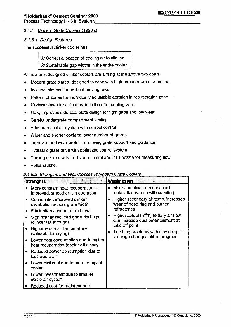
3.1.5 Modern Grate Coolers (1990's)
3. 1.5. 1 Design Features
The successful clinker cooler has:
® Correct allocation of cooling air to clinker
(D Sustainable gap widths in the entire cooler
All new or redesigned clinker coolers are aiming at the above two goals:
Modern grate plates, designed to cope with high temperature differences
Inclined inlet section without moving rows
Pattern of zones for individually adjustable aeration in recuperation zone
Modern plates for a tight grate in the after cooling zone
New, improved side seal plate design for tight gaps and low wear
Careful undergrate compartment sealing
Adequate seal air system with correct control
Wider and shorter coolers; lower number of grates
Improved and wear protected moving grate support and guidance
Hydraulic grate drive with optimized control system
Cooling air fans with inlet vane control and inlet nozzle for measuring flow
Roller crusher
3. 1.5.2 Strengths and Weaknesses of Modern Grate Coolers
Strenghts Weaknesses
• More constant heat recuperation -»
improved, smoother kiln operation
• Cooler inlet: improved clinker
distribution across grate width
• Elimination / control of red river
• Significantly reduced grate riddlings
(clinker fall through)
• Higher waste air temperature
(valuable for drying)
• Lower heat consumption due to higher
heat recuperation (cooler efficiency)
• Reduced power consumption due to
less waste air
• Lower civil cost due to more compact
cooler
• Lower investment due to smaller
waste air system
• Reduced cost for maintenance
More complicated mechanical
installation (varies with supplier)
Higher secondary air temp, increases
wear of nose ring and burner
refractories
Higher actual (m3/h) tertiary air flow
can increase dust entertainment at
take off point
Teething problems with new designs -
> design changes still in progress
Page 130 © Holderbank Management & Consulting, 2000

"Holderbank" Cement Seminar 2000
Process Technology II - Kiln Systems
'HOLDERBANK"
Figure 9 Modern Grate Coolers: Design features
Shorter, wider coolers (IKN)
Hydraulic
grate drive
Roller crusher Wear protected New side Direct aeration Carefully Fixed inlet
grate support seal plates via structural sealed (inclined)
beams compartment
walls
(CPAG) (FLS) (Polysius)
© Holderbank Management & Consulting, 2000 Page 131

'Holderbank" Cement Seminar 2000—i:f]V3=lH :f:l^l
Process Technology II - Kiln Systems
3.1.6 Design Highlights of Modern Grate Coolers
3.1.6.1 Modern Grate Plates
In the mid 1980's, the first modern grate plates were installed in grate coolers by IKN andCPAG. They were designed for the following targets:
Allow for lower air/clinker ratio in the recuperation zone for higher recuperation
Improve clinker distribution across the grate width
Assure that all grate plates are always sufficiently cooled by air
The above targets were reached using the following ideas:
• Higher built-in pressure dropSimilar to the effect of thick bed operation, a higher pressure drop across the plate
reduces the relative influence of variations in permeability of the clinker bed.
• No more fine clinker falling throughFine clinker falling through means loss of heat and thermal stress on the drag chain.
For forced aeration (below) it is mandatory that no material can fall in the air ducts
where it would cut off the air supply.
• Forced (direct) aeration via air ducts
In order to ensure that all plates get enough air, to allow individual allocation of air to
different areas and to avoid that air escapes through gaps, groups of plates are
supplied with air directly via a special duct system
• Tight gaps between plates and plates/casing
Not only through the grate surface, but also through gaps between plates within the
same row as well as from one row to the next, fine clinker can fall through. Thosegaps have to be sealed as well, e.g. by interlinked steps in the plate sides (Fuller,
Polysius) or by bolting them together as packages (IKN).
The modern grate plates are the basis of modern cooler technology. Problems experienced
with the first generation of modern grate plates lead to several detail modifications:
Cracks in corners of air outlet openings
-> Solution: modified shape
Plastic deformation caused premature failure with many designs
-> Solution: thermally flexible plates built from two or more pieces
Preferred plate internal airflow left plates locally uncooled
-> Solution: plate internal guide vanes, optimized air channelling
Modern grate cooler, as the IKN Pendulum Cooler, use also Pneumatic Hopper Drains
(PHD) to withdraw the fine clinker fall through.
Page 132 © Holderbank Management & Consulting, 2000

"Holderbank" Cement Seminar 2000Process Technology II - Kiln Systems
!M|.»:i^?l!a
Figure 10 Modern grate plates
Rg.10a Conventional hole plate
gaps between (§) l
=======—
-
plate and wall ^. ^^===-
transverse gaps@ yZT(1) holes
Fig. 10b Coanda plate (IKN)
Fig. 10c Mulden plate (CPAG)
Fig. 10e Jet ring plate (Polysius)
CFG plate
Fig. 10d Controlled flow grate (Fuller)
Ah- Dtotrttnrtron Ch«nb«ra
PrtmiryAlrOutMi
^
Fig. 1 0f Step plate (KHD)
© Holderbank Management & Consulting, 2000 Page 133

'Holderbank" Cement Seminar 2000 =^Process Technology II - Kiln Systems
3.1.6.2 Air Ducts
The concept of forced aeration, i.e. the idea to bring the air directly to the grate plates
requires a flexible air connection between the (stationary) fan and the moving rows.
Initially, the most obvious and simple approach was chosen: flexible hoses or bellows. IKN,
CPAG, Polysius and Fuller used this solution at the beginning.
However, experience showed that those hoses were sensitive to design (geometry),
installation and material qualities. While many coolers operated without any problem, others
showed frequent rupture of those hoses, very often causing severe plate damage and
consequently kiln downtime.
Meanwhile, all suppliers developed new solutions. Only KHD avoided these problems by
using telescopic ducts from the beginning.
The individual suppliers are now using the following standard solutions:
Telescopic air connector (BMH-CPAG, KHD)
Ball and socket type air connector (FLS, Fuller)
Gate type air connector (Polysius)
Open air beam (IKN)
Page 134 © Holderbank Management & Consulting, 2000

"Holderbank" Cement Seminar 2000Process Technology II - Kiln Systems
!MMj;i:mir
Figure 11 Forced (direct) aeration to moving rows: Flexible ducts
Polysius (old)Polysius (new)
CPAG
Fixed beam for grate
/ Movable sidegirder
Flexible connection
Movable beam for grate
Duct work for movable beam
Duct for fixed beam
Fuller-FLS
© Holderbank Management & Consulting, 2000 Page 135
"Holderbank" Cement Seminar 2000 S5S=
Process Technology II - Kiln Systems
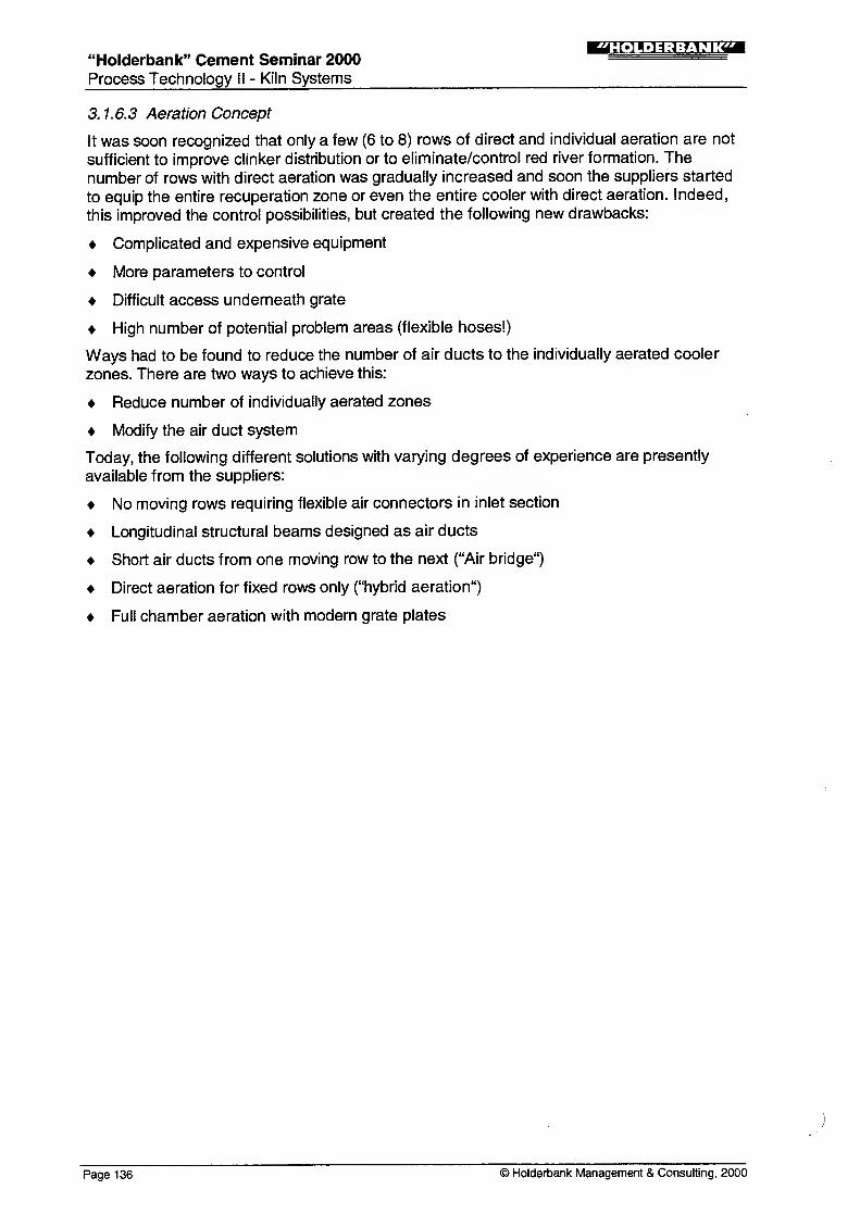
3. 1.6.3 Aeration Concept
It was soon recognized that only a few (6 to 8) rows of direct and individual aeration are not
sufficient to improve clinker distribution or to eliminate/control red river formation. The
number of rows with direct aeration was gradually increased and soon the suppliers started
to equip the entire recuperation zone or even the entire cooler with direct aeration. Indeed,
this improved the control possibilities, but created the following new drawbacks:
Complicated and expensive equipment
More parameters to control
Difficult access underneath grate
High number of potential problem areas (flexible hoses!)
Ways had to be found to reduce the number of air ducts to the individually aerated cooler
zones. There are two ways to achieve this:
Reduce number of individually aerated zones
Modify the air duct system
Today, the following different solutions with varying degrees of experience are presently
available from the suppliers:
No moving rows requiring flexible air connectors in inlet section
Longitudinal structural beams designed as air ducts
Short air ducts from one moving row to the next ("Air bridge")
Direct aeration for fixed rows only ("hybrid aeration")
Full chamber aeration with modern grate plates
Page 136 © Holderbank Management & Consulting, 2000

"Holderbank" Cement Seminar 2000Process Technology II - Kiln Systems
!M|.»:l:M;iTgM
Figure 12 Aeration patterns
BetOftungsscMoo JO/3|(J I3 M
Olact > .
I I I I
Polysius
sectional Mroted
KHD
__5t»*rdb»ftleNstintard "groit «tm
UtOfttt
cnuUr ttt-oted
CPAG
FFFMFWF MP M F M ! «|
J 3 4 3 fl 7 8 » 10 fl 'J
© im ^p/^ia
Fuller-FLS\
r mH Bl. H I—T V 1 _
b H
H B" *
KI..JI. J.
2H2ROWS
Bror butterflyvalve (6) O FUxfele connector (18)
•(13) X Auto P ton dcunpor (2)
) Holderbank Management & Consulting, 2000 Page 137

"Holderbank" Cement Seminar 2000 ^^Process Technology II - Kiln Systems
3.1.6.4 Seal Air (Confining Air)
When direct plate aeration was introduced, the significance of the seal air or confining air
was not properly investigated. It was expected that direct individual aeration of the plates
alone would be enough to get the desired improvement due to better air to clinker allocation.
If the cooler grates were tight and had no or very narrow gaps between moving and fixed
rows or between grate and cooler casing, this would indeed be true. However, real grates
have large gaps, which is one of the reasons why direct aeration was introduced.
The effect of insufficient seal air pressure for direct aerated grates can be explained as
follows:
High resistance in clinker bed (bed thickness, kiln upset, granulometry)
Cooling air sneaks around plate edge to undergrate compartment instead
Clinker dust carried in this air -» abrasion / wear
Gap becomes larger -> seal air can escape -» more "sneak" air
Stops for repair reduce availability and increase operating cost
Today it is generally accepted that partition, sealing and pressurizing of the undergrate
compartments is even more important than with chamber aerated coolers.
Ideally, the partition of the undergrate compartments should repeat the pattern of the
individually aerated grate zones of the grate itself. Since this would lead to very complicated
and expensive designs with difficult access, simpler solutions had to be found.
One of the most common countermeasures is, to install larger seal air fans. It was
interesting to observe the installed cooling air to be gradually increased with each newproject. This did not only lead to larger waste air systems but also to higher cooling fan
motor power which partially offset the savings expected from modern coolers.
The suppliers have proposed the following improvements:
Larger seal air fans
Seal air branched off from cooling air fans
Seal air from booster fan using air from cooling air fans
Undergrate pressure controlled by cooling air fan pressure
Careful sealing of undergrate compartments
No more moving rows in hot inlet zone
Page 138 © Holderbank Management & Consulting, 2000

"Holderbank" Cement Seminar 2000
Process Technology II - Kiln Systems
Figure 13 Seal air systems
t.n.»;i:Mjraa
F M F M F M
? >"©-
1 large SA Fan
F M F M F M
J
I}-©-
1 SA Fan per Comp.
F M F M F M-.;>-
| J—
t
F M F M F M
€>-
SA from Cooling Fan
F M F M F M
3-®-
1 SA Fan; P = const.
--
* 3S <'<"- -rf':*
'. ^'^ :?;^? *S&r
",:. .j.-'. :
: ^;fj." ;;;;;;;
_J
MSA via Booster
F M F M F M
,~.
—t
Chamber Aeration
Seal Fan = Cooling Fan
3.1.6.5 Side Seal Systems
Extremely serious wear problems occurred along the side seal plates on each side of the
grate. Excessive fall through along the sides and shockingly short lifetime of the side seal
plates, mainly in the recuperation zone, were the result. The main reasons for this problem
can be listed as follows:
The same seal element used for lateral and longitudinal movement
Side seal plates fixed to cooler casing
Entire thermal expansion to be compensated by (cold) gap on each side
Side plates used for lateral guidance of the grate (older designs)
More lateral thermal expansion of wider grates for large units
The following new solutions have been developed and are now part of the contemporary
standards:
Entirely new side seal plate concepts
Side seal plates bolted to cross beams of fixed rows (no longer to cooler casing)
Joints for thermal lateral expansion and mechanical longitudinal movement between
moving rows and casing separated
Center grate guide for large coolers
© Holderbank Management & Consulting, 2000 Page 139

"Holderbank" Cement Seminar 2000
Process Technology II - Kiln Systems
:M*.]=N:M<iTaa
Figure 14 Side seal designs
gaps betweenplate and wall
Conventional
gaps betweenplates
CPAG
Fuller-FLS Movahlc Bcnm for pnilc
Polysius
Page 140 © Holderbank Management & Consulting, 2000

"Holderbank" Cement Seminar 2000
Process Technology II - Kiln Systems
!t.».»:i:MJI?
3.1.7 Clinker Crushers
All kiln systems produce larger than normal clinker lumps more or less frequently. Large
balls of material enter the cooler when coating drops during kiln upsets.
Such large clinker masses can only be cooled superficially and contain a lot of heat. Before
being discharged to the clinker conveyor, they must at least be crushed to smaller particles.
All clinker coolers, regardless of the type, are equipped with a clinker crusher . Traditionally,
this is a hammer crusher which has proven to be reliable.
In order to cool large clinker lumps, they must be crushed within the cooler. In reality, this
means installing the crusher before the last grate. Early trials with hammer crushers were
not successful, however.
Based on the idea and experience with roller grate bottoms in shaft kilns (and shaft coolers),
CPAG developed the roller crusher to be used as intermediate crusher in a step cooler.
The advantages of the roller crusher make it also superior at the cooler outlet. Hydraulic or
electric drives as well as different combinations of reversing rollers are available from
various suppliers.
Compared to the hammer crusher, the roller crusher is rated as follows:
Strengths Weaknesses
• low speed • higher initial investment
• low wear • chokes easier
• low dust generation • more difficult to design
• equalization of material rushes
• suitable for high temperatures
• lower power consumption
© Holderbank Management & Consulting, 2000 Page 141

"Holderbank" Cement Seminar 2000
Process Technology II - Kiln Systems
!MMJ;l;M?raa
Figure 15a Hammer crusher
Page 142 © Holderbank Management & Consulting, 2000

"Holderbank" Cement Seminar 2000Process Technology 11 - Kiln Systems
'HOLDERBANK"
Figure 15b Roller crusher
NORMAL OPERATION
ROLLER 1
ROLLER4
5
4 RPM16 RPM
REVERSING OPERATION
ROLLER 1 - A : 4 RPMROLLER - 5 : 180 RPM
CLINKER FLOW DIRECTION >»
CPAG
© Holderbank Management & Consulting, 2000 Page 143

"Holder-bank" Cement Seminar 2000Process Technology II - Kiln Systems
!M|.»:J:MJrT
Figure 16 Heat and air balance of a modern Grate cooler
OAT|Nm3ftg
Tertiary air
Production rate
Heat consumption
Fuel ratio fcitn
02 content at kiln inlet
Ambient pressure
Ambient temperature
Cooler efficiency
Air balance error
Cooler heat balance error
ft26 |Nm3/hg<Q
I
Secondary air
False air kfln
outlet awt
Hlzllll#&o:qb?% * Total cooling air
anmM&vg
HEATBALANCE SUMMARY
INPUT [°C] [kJ/kg,cli]
Clinker from kiln
Cooling air
False air
Water injection
Total of inputs
OUTPUT
sensible heat
sensible heat
sensible heat
1400 1504.2
25 10.8
25 0.1
1515.0
99.3%
0.7%
0.0%
100.0%
Clinker
Secondary air (dust incl.)
Tertiary air
Middle air
Waste air
Radiation loss
Water evaporation
Rest
sensible heat
sensible heat
sensible heat
sensible heat
sensible heat
0.0 j%
Total of outputs
105 66.9 4.4%
1066 379.3 25.0%
1066 695.4 45.9%
0.0 0.0%
300 353.7 23.3%
20.0 1.3%
-0.2
1515.0
0.0%
100.0%
Page 144 © Holderbank Management & Consulting, 2000

"Holderbank" Cement Seminar 2000
Process Technology II - Kiln Systems
!Ml.H;i:M?ITai
Figure 17 Optimization
Cooling curve
clinker temperature
°C
U00
.1200
1000
600
600
400
200
0,5 1,0 1,5 2,0
cooling air quantity
Effect of cooler losses
q kJAg di
3450
3400
3350
d-3300
n
§3250
E3200
3150
Clinker exit temperature
•c
£
>9
4*
\a.
£
\l
V
-
2,5 3,0
Nm 3 /kg cli
10 IS Zfl 2S 10 Nm3 /ltg cli
cooling air quantity
Tcti exit - Tamo
Teli inlet - Tamb= eip (-
cooling air(NmJ
0.77
/kg cli)]
Clinker inlet temperature 1400 °CAmbient temperature 20 °C
3100
q//
T
{'"'"
_..----""*
„.
----'''"'/
/./
/
T°C400
390
Grate cooler efficiency
90
380
370 |
360!
350 gJC
340
330
:^
-150 -100 -50 +50 +100 +150
variation of cooler losses kJ/kg c"
0.7 0,8 0.9 1.0 1.1 1.2 1.3 1.4
combustion air quantity Nm 3/kg cli
3000 3500 4000 4500 5000kiln heat consumption kJAg di
© Holderbank Management & Consulting, 2000 Page 145

"Holderbank" Cement Seminar 2000Process Technology II - Kiln Systems
"HOLDERBANK'
3.1.8 Cooler control
One of the advantages of the reciprocating grate cooler is its high flexibility, due to operating
variables adjustable independently from kiln operation. Usually three main variables are
controlled automatically.
a) Grate speed
In order to prevent the clinker bed resistance from exceeding the pressure capabilities of the
cooling fans (which would mean too little cooling air and danger of heat damage), the bedresistance on the grate should be kept constant.
To do this, each grate section drive is controlled by the undergrate pressure of the first or
second compartment in each grate section. An increase in pressure indicates an increase in
bed resistance (either more material in the cooler or finer material). The reaction is an
increase of the grate speed, causing the bed to become thinner. If the undergrate pressure
decreases, the drive slows down and the bed becomes thicker.
Another possibility is to control only the first grate by the undergrate pressure, and to keep
the speed of the following grates proportional to the speed of the first grate.
More sophisticated control systems use the weighted average of several undergrate
pressures to control first grate speed. In many cases, however, control systems amplify
fluctuations from the kiln instead of smoothening them. Increasing the bandwidth of the
control system has shown good results in several cases.
b) Airflow
This control is complementary to the grate speed control. It maintains a constant volume of
cooling air entering the cooler independently from the grate underpressure.
Each cooling fan is equipped with a piezometer sensor which will recognize an increase or
decrease of the airflow and cause the cooling fan damper to close or open (in case of inlet
vane damper control) or the fan motor speed to decrease or increase (in case of variable
speed fan drives).
During normal conditions the cooling fans operate at about 2/3 to 3/4 of their maximumperformance so that enough spare capacity is left to cope with eventual kiln rushes.
Together, grate speed and air flow control will on one hand ensure a sufficient cooling air
supply to the cooler and, on the other hand, tend to provide more uniform combustion air
temperature to the kiln.
c) Hood draft
The third component of the cooler control system is the hood draft control.
An automatically controlled grate cooler can improve the whole kiln operation and allows the
operator to concentrate on other problems.
The kiln hood pressure is used to regulate the cooler vent air fan speed to maintain a
constant pre-set draft. As the draft tends to become positive, the cooler vent fan speed is
increased. This takes more air from the cooler and maintains the draft setpoint. As with the
other controls, reaction in the opposite direction is just as important.
Coolers with radiation walls (IKN) allow hood draft control by one of the first cooling air fans.
Page 146 © Holderbank Management & Consulting, 2000

"Holder-bank" Cement Seminar 2000
Process Technology II - Kiln Systems
;t>».»:i:mrrga
Figure 18 Cooler control
--(5)
X)-g11JMAAAAAAAA/vwvwwi
® i ®-
<? <j> tj> <j> <i>t? tj> \
IT IT IT IT I
Cn K?) Hn *-(0
Conventional grate cooler
control with 3 loops
[PI) (P2) (P3) (P4) @-
i ' i i i i ntoto to to to to
i i
i i i
First grate speed control
with weighted pressures
from several compartments
//IA
K-U*AAAAAAAAMAAAAAAA*
X'^^OOOOC
rt*
-r-— a —
i
--—r-\tp (p tp 1
Kiln hood draft control
by cooling air fan
(IKN with radiation wall)
IT IT IT I
© Holderbank Management & Consulting, 2000 Page 147

"Holderbank" Cement Seminar 2000Process Technology II - Kiln Systems
!Ml.»;l=M?ITai
3.1.9 Cooler Dedustinq
While dedusting of kiln exhaust gas can be commonly solved by using one type of dust
collector only (electrostatic precipitator), the choice of the most adequate system for
dedusting clinker cooler vent air raises quite often many discussions. This choice problem is
basically a result of the special and fluctuating conditions of the vent air to be dedusted:
normal operation kiln upset
airflow (actual volume) % 100 up to 150
air temperature °C 200 - 250 up to 450
air dew point °C 5-20 5-20
dust load g/Nm3 5- 15 25-35
The dust particle size distribution can vary in a wide range depending on the burning
conditions in the kiln.
Dimensioning of the dedusting equipment must take into account the worst conditions, in
order to maintain the required clean gas dust content even at kiln upset condition.
The types of dust collectors for this application are compared below. Today's trend is:
multiclones will no longer be tolerated in new and many existing plants
gravel bed filters have proved to be inefficient and expensive
use of electrostatic precipitators is possible without restriction
bag filters with cooling of the vent air in a heat exchanger are often used nowadays
»Typeoi collector Strengths Weaknesses
multiclone simple poor efficiency for particles
low investment cost < 20 urn
low space requirement
not sensitive to
temperature peaks
efficiency sensitive to gasflow fluctuation
comparatively high
pressure loss
high operating cost
electrostatic precipitator low pressure loss
low operating cost
big unit required or use of
pulse generator -> high
low maintenance costinvestment cost
possibly water injection
required
gravel bed filter not sensitive to
temperature peakshighest investment cost
highest pressure loss
high operating cost
bag filter high efficiency
relatively low investment
cost
no bags for temperatures
up to 450°C -» precooling
required
high pressure loss
high operating cost
high maintenance cost
Page 148 © Holderbank Management & Consulting, 2000

"Holderbank" Cement Seminar 2000
Process Technology II - Kiln Systems
Figure 1 9 Grate cooler dedusting
Mi.ld;l:M>MTaa
Multiclone Gravel bed filter
Electrostatic precipitator Air to air heat exchanger
and bag filter
© Holderbank Management & Consulting, 2000 Page 149

"Holderbank" Cement Seminar 2000Process Technology II - Kiln Systems
!Ml.H;W:Urca
3.1.10 Developments
Air recirculating (Duotherm) cooler
A patent has been taken out in 1 970 by the "Societe des Ciments Francais" concerning the
recirculation of the vent air after sending it through a heat exchanger.
The first application of the unconventional system has been realized in 1970 at the
Beaucaire plant of the above mentioned company, on a 1 500 t/d Fuller cooler.
Initial experience gained with this installation was very satisfactory.
Only few installations using this principle have been realized, e.g. in the Ulco plant. Themain advantages and disadvantages of this system are:
Strengths Weaknesses
• no dust emission at all
• simple
• low investment cost
• heat recovery possible (at various
temperature levels)
• extension possible by adding further
heat exchange units
• possible wear of fan blades
(preventative measuresnecessary)
• maintenance and operating
costs higher than conventional
cooler dedusting system with EP
Modern cooler technology and problems in some cases have pushed this idea in the
background. However, it might be reactivated if it can be combined with modern cooler
systems.
Dual pass cooler
A completely new principle of cooling in a grate cooler has been introduced by Polysius in
1994: the dual pass cooler or REPOL-ZS.
This cooler can be considered a two-grate cooler with intermediate crusher where grate 1
and 2 are identical.
The hot, 1400°C clinker from the kiln is fed on top of a layer of colder clinker already laying
on the cooler grate. At the end of the grate, the now cold lower clinker layer is extracted via
a special system consisting of reciprocating bars and a hopper. The upper layer which hasreached about 500°C passes a roller crusher and is then returned to a intermediate hopperbelow the kiln from where it is fed onto the empty grate to pass the cooling air a secondtime, this time below the fresh hot clinker.
One 1 400 t/d unit is in operation in Germany using Jet-Ring technology. With less than
1 .6 Nm3/kg cooling air, extremely low clinker temperatures have been reported. The crucial
problems of this solution are intermediate transport and storage.
In spite of the compact size, high cooling degree with low air flow and low plate
temperatures, this cooler will only be successful if the intermediate temperature level can beincreased and the heat losses reduced.
Page 150 © Holderbank Management & Consulting, 2000

"Holderbank" Cement Seminar 2000
Process Technology II - Kiln Systems
Figure 20a Non venting cooler
IMM^MJICT
Normol 200 - 250 «C
Upset up to 400 'C
Figure 20b Dual pass cooler (Polysius)
roller
crusher
partially cooled
.clinker (~500°C)
> > i -r-
i—i—p^ri"
special bucket intermediate reciprocating grate
elevator clinker bin jet ring plates with
direct aeration
finished cooled
clinker (50°C)
© Holderbank Management & Consulting, 2000 Page 151

^derbank-Cemen, Seminar 2000Ifl-n-M^jWm
Process Technology II - Kiln Systems
3.2 The Cross Bar Cooler
3.2.1 Principle
F.L.Smidth and Fuller developed together the new SF (Smidth - Fuller) Cross Bar Cooler
representing a completely new concept.
The basic idea was to develop a cooler in which conveying of clinker and air distribution
systems are separated. The SF cooler has a clinker conveying device installed above an
entirely fixed grate.
In addition the cooler should be less complicated, more efficient and easier to operate than
other grate coolers on the market. Sealing air is eliminated and the distribution of air is
optimized for all modes of operation
The thermal behavior of the SF cooler (e.g. heat balance, recuperation) is similar to the
other grate coolers.
3.2.2 Main features
• One inclined fixed grate.
• Clinker conveying by cross bars, separate from air distribution.
• No thermal stress of grate.
• Minimum wear on grateplates due to a dead layer of clinker (50 mm) protecting the grate
surface. The thickness is given by the space between the cross bars and the grate.
(Anticipated service life time at least 5 years)
• Dynamic flow control unit (mechanical flow regulator) for each grate plate. Themechanical flow regulator maintains a constant airflow through the grate and clinker
bed, irrespective of the clinker bed height, particle size distribution, temperature, etc.
• No fall through of clinker to the undergrate compartment.
-> Eliminating undergrate clinker transport resulting in low installation height
for new plants.
• Easy cooler operation by elimination of sealing air and automatic control of air
distribution.
• Modularized cooler concept —> short delivery and installation time.
• Different drive speeds across the cooler possible.
-» Additional control of clinker distribution.
• Fewer and less expensive wear parts (easy to replace).
Easy visual inspection of undergrate compartment (clean undergrate, windows).
Sustainably high thermal cooler efficiency throughout the lifetime of the cooler.
-> Reduced system heat consumption.
•
Page 1 52 © Holderbank Management & Consulting, 2000

"Holderbank" Cement Seminar 2000
Process Technology II - Kiln Systems
!MI.»;J:MJITai
Figure 21 a: SF Cross Bar Cooler
Figure 21 b: SF cooler grate with cross bars
© Holderbank Management & Consulting, 2000 Page 153

"Holderbank" Cement Seminar 2000Process Technology II - Kiln Systems
:mmj;1=M?it
3.2.3 Strengths and Weaknesses
Strengths
No clinker fall through (no hoppers, nodragchain).
The grate is protected from
overheating.
Very high availability is expected.
Wear and tear affects only the
conveying system and not the air
distribution system.
For each plate, the cooling air is
individually controlled.
The amount of cooling air is about 1 .6
to1.8Nm3/kg.
Reduced height and maintenancerequired since the undergrate clinker
transport can be dropped.
Time for installation is short due to
modular concept.
Weaknesses
• The clinker bed seems to be influenced
by the conveying reciprocating cross
bar, resulting in disturbed clinker
layers.
• In case of fine clinker and coating
drops, air breakthroughs can occur.
• The performance of the mechanical
flow regulator (amount of cooling air)
and its distribution is yet to beassessed.
• Airflow through the fixed grate at the
cooler inlet (CIS) can generate dust
and dust cycle.
i
<-;S.i S*VS
Remark: So far, no SF Cross Bar Cooler is in use within the "Holderbank" group andtherefore no first hand experience is available. Worldwide, there are only three SFcross bar coolers installed. Two of a capacity of 450 t/d and one of 2000 t/d. (as of
January 1 999)
Figure 22a: Cross Bars: Easy to replace wear parts
Page 154 © Holderbank Management & Consulting, 2000

"Holderbank" Cement Seminar 2000
Process Technology II - Kiln Systems
!r.n.»:i:M?irai
Figure 22b: Mechanical fiow regulator
A\u,. 1^
Figure 22c: Modular concept: One module
© Holderbank Management & Consulting, 2000 Page 155

-'Holderbank" Cement Seminar 2000Process Technology II - Kiln Systems
3.3 The Travelling Grate Cooler
3.3.1 Principle
The traveling grate cooler (Recupol) was originally developed by Polysius for use in
combination with grate preheater (Lepol) kilns. Using the same principle and similar
technology, it uses the same wear parts. The following main components can be
distinguished:
• Casing with kiln hood and connections for air at different temperature levels
• Inlet with water cooled chute (2nd generation) and pulsator
• Traveling grate with return carrying idlers and drive system
• Aeration system with fans, undergrate compartments
• Riddling extraction system with chutes, flap gates, hoppers and transport
• Clinker crusher
Material transport
The clinker is carried by a horizontal traveling grate which works like a stationary
caterpillar chain with perforated chain plates. In contrast to the reciprocating grate
cooler, the clinker does not tumble over plate edges, but remains as undisturbed layered
bed from inlet to discharge.
Heat exchangeHeat exchange takes place, like for the reciprocating grate according to the
cross current principle. Because the layers remain, it should be even better, at least
theoretically.
Cooling air
Ambient air is blown by a number of cooling air fans to underneath of the travelling grate
plates carrying the clinker. Pressure and flow criteria of cooling air are basically as for
the reciprocating grate cooler.
Water cooled inlet chuteIn order to achieve rapid cooling in the inlet section, but also to protect the travelling
grate from the highest clinker temperatures, Recupol coolers were equipped with a
water cooled inlet chute.
Key figures / KPI2
Specific -grate loading: 25 - 30 t/d m (design)
Largest units: 3000 t/d (Lagerdorf kiln 1 0)
Page 156 © Holderbank Management & Consulting, 2000

"Holderbank" Cement Seminar 2000
Process Technology II - Kiln Systems
Figure 23 Travelling grate cooler
MI.H:i:MJirai
17 16
Turning shaft
Supporting girder
Water cooled steel plate
Shaft for upper traveling
routeSiding plate
Chain curtain
Chain wheel
Drive shaft
10 Strip off grate
11 Clinker breaker
12 Grate bolt
14 Shaft for lower
traveling route
15 Pulsator
16 Blower nozzle
17 Drag plate
18 Slide bearing
19 Sealing elements
20 Chain link
21 Grate plate
22 Flap gate
© Holderbank Management & Consulting, 2000 Page 157

"Holderbank" Cement Seminar 2000Process Technology II - Kiln Systems
"HOLDERBANK"
3.3.2 Strengths and Weaknesses
Travelling grate cooler compared to reciprocating coolers
Strengths Weaknesses
• Possibility of replacing grate plates
during operation (on the returning part)
• Undisturbed, layered clinker bed is
better for optimum heat exchange
• Larger machine for the samegrate area equipment requiring
more space and higher civil cost
• Lower specific grate loadings
adding further to overall size
• More expensive to build than a
reciprocating grate cooler
• The absence of clinker
movement (see above) wasoften considered adisadvantage because of caseswhere a solid (fritted) layer on
top of the clinker bed made it
impermeable for air. For this
reason, pulsators were installed
for first'cooling fans.
• Much higher maintenance
requirement with ageing
equipment
• Heat loss via cooling water for
inlet chute
Due to the mentioned weaknesses, Polysius eventually decided to develop their ownreciprocating grate cooler (Repol) around 1 980:
Page 158 © Holderbank Management & Consulting, 2000

"Holderbank" Cement Seminar 2000
Process Technology II - Kiln Systems
!Mi.H;i:Mjrraa
Figure 24 Travelling grate cooler: Design details
inlet seal
Inclined installation
Recupol grate
with slot plates
© Holderbank Management & Consulting, 2000 Page 159

'Holderbank" Cement Seminar 2000"
=^==
Process Technology II - Kiln Systems
4. ROTATING COOLERS
4.1 The Rotary Cooler or Tube Cooler
4.1.1 Principle
The rotary cooler consists mainly of a rotating cylinder, similar to a rotary kiln.
The clinker is fed through the inlet chute and is then cooled by air while being transported
towards the outlet end. Cooling is performed in countercurrent flow. The tube is equipped
with internal lifters which improve the heat transfer. About 2/3 (66%) of the cooler length is
lined with refractory bricks.
The rotary cooler is of simple design and is the oldest type of clinker coolers. It was seldom
used for modern, large kiln systems. Therefore comparatively little design and operating
experience is nowadays available for rotary coolers above 2000 t/d. However, the
application of rotary coolers still offers certain advantages. Presently units up to 4500 t/d
(dimensions dia 6.3/6.0 x 80 m) are in operation. It will be interesting to follow the future
development of large rotary coolers.
4.1.2 Design Features
Arrangement of the rotary cooler is normally in the extension of the kiln axis; in manycases the reverse manner (underneath the kiln) has been applied.
The diameter of the cooler is similar to that of a corresponding suspension preheater
kiln. Likewise the rotating speed is in the same range as for the kiln (max. 3 rpm).
Length/diameter ratio: L/D -10.
Many cooler tubes are designed with an extension in diameter in order to reduce air velocity.
The inclination is comparatively high (in the order of 5%).
Like for all rotating coolers, the internal heat transfer equipment is an important part of
the rotary cooler. Its task is to generate additional area by scattering the clinker without
generating too much dust. Basically a similar design may be applied as in a planetary
cooler tube (see next chapter) however the following differences must be considered:
• The clinker falling heights are larger. Wear protection of shell and lining is essential.
• At a comparative length position the clinker in a rotary cooler is hotter than in a
planetary cooler.
Page 1 60 © Holderbank Management & Consulting, 2000

"Hoiderbank" Cement Seminar 2000
Process Technology II - Kiln Systems
'HOLDERBANK*
Figure 25 Rotary cooler
fi I I I I.
air
clinker
\ta
I I i
brick lining
l t' '
I 1 I I
inlet chute
wn
TW
lifters
crushing teeth
cast lifters
© Hoiderbank Management & Consulting, 2000 Page 161

"Holderbank" Cement Seminar 2000Process Technology II - Kiln Systems
:M%.U:bhuinm
The following zones can typically be distinguished in a rotary cooler (simplified):
A Lined inlet zone
B Lined crushing teeth zone(metallic teeth)
C Lined cast lifter zone, lining protected by wearing plates
(at least in the second half)
D Cast lifter zone, shell protected by wearing plates
(having air gap, giving also insulating effect)
E Sheet metal zone with wearing plates
Construction materials have to be selected according to the high temperature and wearrequirements.
4.1.3 Cooling performance
Depending on the design and the shape of the lifters clinker outlet temperature usually
tends to be high. In many cases it is necessary to enhance the cooling by injecting water
into the tube (up to 60 g/kg clinker) in order to reach reasonably low clinker temperatures of
100°to150°C.
The cooling efficiency (heat recuperation) is equal or even slightly better than on a planetary
cooler.
4.1.4 Strengths / Weaknesses
Strengths Weaknesses
• Simplicity of cooler design, robust
piece of equipment.
• No special mechanical problems
comparable to a rotary kiln.
• No control loops.
• Easy commissioning.
• No waste air and therefore no
dedusting equipment required
• Electrical energy consumption up to 5
kWh/t lower compared to grate cooler.
• Rotational speed can be adjusted and
therefore upset kiln conditions can be
handled easier than with a planetary
cooler.
• Suitable for AS type precalcining
system tertiary (extraction of hot air is
possible).
• Not recommended for large units
(above 2000 t/d)
• Formation of build-ups ("snowmen") in
the inlet chute. A water-cooled chute or
a dislodging device is required in suchcase.
• Clinker outlet temperatures tend
to be high and therefore water injection
is usually required.
• Due to large falling height wearprotection in the tube must bereinforced (compared to a planetary
cooler).
• High kiln foundations are required.
• Cooler inlet seal can contribute to
additional false air inlet.
Page 162 © Holderbank Management & Consulting, 2000

"Holderbank" Cement Seminar 2000Process Technology II - Kiln Systems
ii'H-Uii-.hurzm
Figure 26 Internal transfer equipment for rotary and planetary coolers
4.2 The Planetary Cooler
4.2.1 Principle
The planetary cooler is based on the same cooling principle as the rotary cooler in the
preceding chapter. However, the essential difference of a planetary cooler is the number of
individual cooling tubes. The flow of clinker is subdivided into 9 to 1 1 (usually 1 0) cooling
tubes which are installed around the kiln circumference at the kiln outlet (see Fig. 15).
Therefore the planetary tubes follow the kiln rotation. Because of their connection to the kiln
rotation, planetary coolers do not need a separate drive. This fact already illustrates one
main advantage of the planetary cooler: its simplicity in operation.
Strictly speaking the cooling of clinker does not only start in the cooling tubes but already in
the kiln. In the case of a planetary cooler the kiln burner pipe is always inserted into the
rotary kiln so that a cooling zone behind the flame of 1 .5 to 2.5 kiln diameters is created.
This zone is called the "kiln internal cooling" zone and must be considered as an integral
part of any planetary cooler. In this zone the temperature of the clinker drops from 1450° to
1200 - 1300°C. This temperature reduction is important for the protection of the inlet
opening, the elbow and the first section of the cooling tubes.
© Holderbank Management & Consulting, 2000 Page 163

"Holderbank" Cement Seminar 2000
Process Technology II - Kiln Systems
iMM^mrrai
After this first cooling in the kiln internal cooling zone the clinker falls into the elbows whenthey reach their lowest point of kiln rotation. The hot clinker is then cooled by air in
counterflow (the amount of air equals the amount of secondary air). The air is heated up to
approx. 700°C. The clinker reaches final temperatures which are typically in the range of
140°to240°C.
A considerable amount of heat is also transferred to ambient by radiation and convection
since approx. 75% of the cooler shell is not insulated.
4.2.2 Historical
Planetary coolers have been used since 1920. When large kiln units and grate coolers were
developed planetary coolers were abandoned for many years. But about 1 966 planetary
coolers of large capacities were introduced. At that stage serious mechanical problems
occurred on these first large planetary coolers. As a consequence a lot of work had to be
done in order to improve the mechanical design of planetary coolers. As a result of
extensive computer calculations and operating experience the planetary cooler became amechanically reliable piece of equipment.
In the late 1970's, the design had reached a high standard and a considerable level of
perfection. Units of up to 5000 t/d were envisaged. With the demand for permanently larger
units using precalciner technology with separate tertiary air dusts, the boom period of the
planetary coolers came to an end.
Figure 27 Planetary cooler
Page 164 © Holderbank Management & Consulting, 2000

"Holderbank" Cement Seminar 2000 =™Process Technology II - Kiln Systems
4.2.3 Design features
Planetary coolers in the late 1970's had the following design features:
Shell extension:
The kiln shell is extended beyond the cooling tube outlets and is supported by an
additional roller station.
Fixation of cooling tubes:
Fixed support of cooling tubes near inlet and loose support near outlet end.
With larger coolers, the cooling tubes can consist of two separate sections requiring three
supports. In that case two fixed supports are located near inlet and near outlet and a loose
support is located at the interconnection point in the middle.
Design of cooler supports:
The kiln shell is reinforced (high thickness) where the cooler support structure for the
cooler is welded on. The support structure (base and brackets) itself is of heavy design
consisting of reinforcement ribs and box beams.
Cooler length:
Length/diameter ratio of tubes is approx. 10:1
Inlet openings:
The inlet openings to the cooler elbows weaken the kiln shell and high mechanical and
thermal stresses occur in that zone.
The openings are made of oval shape and the kiln shell is considerably reinforced in its
thickness (up to 140 mm in large kilns) in order to compensate for the weakening.
In some cases a diagonal retaining bar (made of high heat resistant steel) is
incorporated in the opening in order to avoid that large lumps can enter the cooler.
Kiln-to-elbow joint:
This joint is designed in a manner that no forces due to thermal expansion and
deformation are transmitted from elbow to kiln.
Elbow:
In order to prevent that clinker is falling back into the kiln while the opening is on top
position, the position of the cooling tube is displaced back against the direction of
rotation. The elbow design must avoid excessive dust backspillage and wear.
4.2.4 Internal heat transfer equipment (see Fig. 26)
Cooling performance depends strongly on efficient lifters of solid and durable design. Since
high heat resistant metallic lifers are available on the market also the high temperature
zones can be adequately equipped. Special high temperature alloys can be used for this
purpose. They can withstand maximum temperatures of up to 1 1 50°C. These alloys are
usually characterized by a high chromium content of approx. 30% Cr. Other elements as Ni
or Mo can occur in various proportions. Fig. 26 shows a typical arrangement of heat transfer
internals. Breaking teeth are applied in the hottest zone. They are able to crush large lumps
of clinker and create also a tumbling effect, which improves the heat transfer. They are of
heavy design and mounted on separate supports.
The first rows of lifters must be carefully selected regarding design and material. Their
functioning is very important since they also protect the following lifters from overheating.
© Holderbank Management & Consulting, 2000 Page 1 65

"Holderbank" Cement Seminar 2000
Process Technology II - Kiln Systems
!MM=u=M?traa
Figure 28a Temperature profile in planetary cooler
<— ! — cooling air
Figure 28b Water cooling for planetary coolers
a) external water spray
nrrr
H,0circulation
pump
b) internal water spray
I
—
r—
SiH,0
I
H,0
Page 166 © Holderbank Management & Consulting, 2000

i;Ml.»:l:f3gE"Holderbank" Cement Seminar 2000 ^^Process Technology II - Kiln Systems
5. VERTICAL COOLERS
5.1 The Gravity Cooler (G - Cooler)
The Claudius Peters Company have developed the "g-cooler". The letter "g" stands for
gravity since clinker movement is performed by gravity.
This cooler is designed as an after cooler and can therefore only be used in connection with
a primary cooler such as a short grate cooler or a planetary cooler. The installation together
with a grate cooler is shown in Fig. 29.
An intermediary crusher reduces the clinker size to 20 - 30 mm. The material of approx.
400°C is then filled by a drag chain into a vertical shaft. Cooling is performed by horizontal
rows of tubes which are cooled by internal air flow. The heat is therefore exchanged
indirectly and the air remains dust-free. The clinker slowly drops down (at a speed of 20 -
30 mm/s) and reaches final temperatures of approx. 1 00°C at the discharge.
There is no dedusting equipment required for the cooling air. However, the system
according to Fig. 29 as a whole is usually not free from dusty waste air. In case of a
suspension preheater kiln system there is still some waste air required on the grate cooler
since the kiln cannot take all the hot air produced during the first cooling step. In addition, a
marginal amount of dusty air is produced by the g-cooler itself (top and discharge).
The application of this cooler type is often considered for kiln extension projects. If an
existing grate cooler (or a planetary cooler) has to be operated at higher capacity the newclinker outlet temperature can become too high. In this case the clinker temperature can be
reduced by a g-cooler used as an aftercooler.
5.2 The Shaft Cooler
A shaft cooler can be operated waste-air-free and theoretically offers an ideal
countercurrent heat exchange and thus high recuperating efficiency. Based on the idea the
first large shaft cooler was designed and constructed on a 3000 t/d kiln in 1 973.
The experience gained in the plant shows that it is possible to operate such equipment but
some serious disadvantages have to be taken into account:
All depends of the clinker granulometry! Theoretically, an extremely uniform clinker
granulometry having no fines and no coarse material would be required. This is hardly
achievable in a cement kiln. Therefore, fluctuations occur.
High cooling air quantity (= secondary air) of 1 .05 Nm3/kg cli is required but even so the
clinker exit temperature of 350°C is very high.
High power consumption (10 kWh/t)
For the above reasons, the technical realization is not yet solved. The shaft cooler so far is
not a reasonable alternative to the conventional clinker coolers.
© Holderbank Management & Consulting, 2000 Page 1 67

"Holderbank" Cement Seminar 2000
Process Technology II - Kiln Systems
iMM^M'ITSM
Figure 29 Gravity cooler (g-cooler, CPAG)
to wasteair dedusting
JrH,
£)-ir-j j__, __j
^clinker discharge
approx. 350 *C
g- cooler
Jttittiitttr
*
f=._
Q <J) Q Q (J) (J)
clinker discharge
max. 85°C absolute
Figure 30 Shaft cooler
Page 168 © Holderbank Management & Consulting, 2000

"Holderbank" Cement Seminar 2000
Process Technology II - Kiln Systems
!r.».»:i:MJirai
Figure 31 Claudius Peters CPAG: Combi Cooler
CLAUDIUS PET
Figure 32 FLS: Coolax Grate Cooler
© Holderbank Management & Consulting, 2000 Page 169

"Holderbank" Cement Seminar 2000Process Technology II - Kiln Systems
!N».»;i=M?lfaa
Figure 33 Fuller: Controlled Flow Grate (CFG) Cooler
Figure 34 IKN: Pendulum Cooler
Page 170 © Holderbank Management & Consulting, 2000

"Holderbank" Cement Seminar 2000
Process Technology II - Kiln Systems
Figure 35 KHD: Pyrostep Cooler
!M|.»:i=M?ITa
Figure 36 Polysius: Repol RS Cooler
© Holderbank Management & Consulting, 2000 Page 171

-'Holderbank" Cement Seminar 2000 ========Process Technology II - Kiln Systems
Page 172 © Holderbank Management & Consulting, 2000