pg-prv
DESCRIPTION
pg-prvTRANSCRIPT

Water Pressure Reducing Valves
w a t t s . c o m
Now includes our
LEAD FREE*
product offering


1
Table of ContentsGeneral Information . . . . . . . . . . . . . . . . . . . . . . . . . . . . . . . . . . . . . . . . . . . . . . . . . . . . . . . . . . . . . . . . . . . . . . . . . . . . 2 – 5
Performance Curves . . . . . . . . . . . . . . . . . . . . . . . . . . . . . . . . . . . . . . . . . . . . . . . . . . . . . . . . . . . . . . . . . . . . . . . . . . . 6 – 7
Water Pressure Reducing Valves . . . . . . . . . . . . . . . . . . . . . . . . . . . . . . . . . . . . . . . . . . . . . . . . . . . . . . . . . . . . . . . . . 8
Series LFU5B – Water pressure reducing valves . . . . . . . . . . . . . . . . . . . . . . . . . . . . . . . . . . . . . . . . . . . . . . . . . . . . . . . . 8 – 9
Series LF25AUB-Z3 – Water pressure reducing valves . . . . . . . . . . . . . . . . . . . . . . . . . . . . . . . . . . . . . . . . . . . . . . . . . 10 – 11
Series LFX65B – Water pressure reducing valves (1⁄2" – 2") . . . . . . . . . . . . . . . . . . . . . . . . . . . . . . . . . . . . . . . . . . . . . 12 – 13
Series LF45B-M1 – Water pressure reducing valves (3⁄4" – 1") . . . . . . . . . . . . . . . . . . . . . . . . . . . . . . . . . . . . . . . . . . . 14 – 15
Series LFN45B-EZ – Water pressure reducing valves (3⁄4" – 1") . . . . . . . . . . . . . . . . . . . . . . . . . . . . . . . . . . . . . . . . . . 16 – 17
Series LF223, LF223S – High capacity water pressure reducing valves . . . . . . . . . . . . . . . . . . . . . . . . . . . . . . . . . . . 18 – 19
Series LFN223B, LFN223BS – Super capacity water pressure reducing valves . . . . . . . . . . . . . . . . . . . . . . . . . . . . . 20 – 21
Series LFN223F, LFN223FS – Flanged super capacity water pressure reducing valves . . . . . . . . . . . . . . . . . . . . . . 22 – 23
Series LF127W and LFF127W – High capacity water pressure reducing valves . . . . . . . . . . . . . . . . . . . . . . . . . . . . 24 – 25
Series 2300 – Direct operated water pressure reducing valves . . . . . . . . . . . . . . . . . . . . . . . . . . . . . . . . . . . . . . . . . . . . . . 26
Series 115/1115 – Water pressure reducing automatic control valves . . . . . . . . . . . . . . . . . . . . . . . . . . . . . . . . . . . . . . . . 27
Series LFN250, LFN250B – Iron body water pressure reducing valves with integral strainer . . . . . . . . . . . . . . . . . . . . . . 28
Series LF26A, LF263A – Small water pressure reducing valves . . . . . . . . . . . . . . . . . . . . . . . . . . . . . . . . . . . . . . . . . . . . . . 29
Series SS263AP – Stainless steel water pressure reducing valves . . . . . . . . . . . . . . . . . . . . . . . . . . . . . . . . . . . . . . . . . . . 30
Series P60-M1 – Plastic miniature water pressure reducing valves . . . . . . . . . . . . . . . . . . . . . . . . . . . . . . . . . . . . . . . . . . . 31
Series LF560, LFH560 – Water pressure reducing valves . . . . . . . . . . . . . . . . . . . . . . . . . . . . . . . . . . . . . . . . . . . . . . . . . . . 32
Series LF123LP – Water pressure reducing valves . . . . . . . . . . . . . . . . . . . . . . . . . . . . . . . . . . . . . . . . . . . . . . . . . . . . . . . . 33
Series LF215 – Super sensitive low pressure water pressure regulators . . . . . . . . . . . . . . . . . . . . . . . . . . . . . . . . . . . . . . . 34
Model 276H300, IWTG – Hose connection gauges . . . . . . . . . . . . . . . . . . . . . . . . . . . . . . . . . . . . . . . . . . . . . . . . . . . . . . . . 35
Series LFDPG-3 – Center back-entry pressure gauges . . . . . . . . . . . . . . . . . . . . . . . . . . . . . . . . . . . . . . . . . . . . . . . . . . . . 36
Series LFDPG-5 – Top entry pressure gauges . . . . . . . . . . . . . . . . . . . . . . . . . . . . . . . . . . . . . . . . . . . . . . . . . . . . . . . . . . . . 37
Jumper Kits – Temporary bypass for water pressure reducing valves . . . . . . . . . . . . . . . . . . . . . . . . . . . . . . . . . . . . . . . . . 38

2
Why Do You Need a Watts Water Pressure Reducing Valve?
Common practice and analysis indicate that 50psi or less is sufficient inflow pres-sure for most home and commercial purposes. The higher the pressure the more water resources are wasted. Watts water pressure reducing valves help save money, energy, system maintenance, and wastewater returned to the environment (see Fig. 1).
• Water Savings: Twice as much water flows through a system at 150psi pres-sure than at 50psi. Much of this addi-tional water is wasted.
• Energy Savings: If less water flows through the system, then less energy is needed to heat domestic hot water. Calculations show that a Watts water pressure reducing valve can save as much as 30% on domestic water heating costs.
• Wastewater Savings: When the com-munity’s wastewater treatment load is reduced, cost benefits accrue to both the environment and your bottom line. Many municipalities prorate sewer usage fees based upon the water meter reading. Fig . 1 – Faucet with 10
minutes running time
General InformationEnsuring Practical, Safe Working Water Pressure
Water pressure reducing valves have been in use since 1874, when Watts’ regulators were used to reduce the pressure of incoming water to industrial operations. Subsequently, they have been adapted for residential and com-mercial use.
The most important and practical rea-son that water pressure reducing valves (WPRVs), also known as pressure regu-lators, are used is protection against the effects of high water main pressures.
Municipal and private water supply com-panies use pumps and pumping stations
to boost water supply pressures in sup-ply mains in order to supply water for fire fighting, to overcome loss of pressure as the elevation increases in high rise build-ings, and to maintain water supply in water towers and supply tanks. Pressure in water supply mains can exceed 200psi.
Most plumbing codes require water pres-sure reducing valves on domestic sys-tems where the municipal water main’s pressure exceeds 80psi. Higher pres-sures could rupture pipes, damage fix-tures, and injure the people using them.
Promoting Water Conservation
High water pressures waste water. Anyone concerned with conserving water, a vital and increasingly expensive resource, should be interested in reducing water consumption and the associated costs. Many municipalities today not only charge homeowners and businesses high rates for water consumption, but also charge consumers equally high rates for the disposal of wastewater. Furthermore, conserving water reduces the excess
energy required for heating additional hot water. Watts water pressure reducing valves have proven themselves over the years by ensuring efficient water distribu-tion, longer life for the entire plumbing system, and considerable savings in water and energy consumption.
What is a Water Pressure Reducing Valve?
There are two types of water pressure reducing valves: direct- acting and pilot-operated. Both use globe- or angle-style bod-ies. Valves used on smaller piping diameter units are cast from brass; larger piping diameter units are made from ductile iron. Direct-acting valves, the more popular type of water pressure reducing valve, consist of globe-type bodies with a spring-loaded, heat-resistant diaphragm.
This diaphragm is connected to the outlet of the valve which in turn acts on a spring. This spring holds a
pre-set tension on the valve seat installed with a pressure equalizing mechanism for precise
water pressure control.
Pilot-Operated Valve Direct-Acting Valve

3
Water pressure regulators are installed in series directly after the water meter in homes, commercial buildings, and manufacturing plants. The water pressure reducing valve automatically reduces the pressure from the water supply main to a lower, more sensible pressure. Water entering the valve from municipal mains is constricted within the valve body and directed through the inner chamber; this inner chamber is controlled by an adjust-able spring-loaded diaphragm and disc.
Even if the supply water pressure fluctu-ates, the pressure reducing valve ensures a constant flow of water at a functional pressure (as long as the supply pressure does not drop below the valve’s pre-set pressure).
Thermal Expansion Bypass Technology
The installation of a water pressure reducing valve on the potable water distribution line creates a closed plumbing system, since water can no longer return to the supply main. A water heater installed in the system will cause the water in the heater to expand, a condition known as ther-mal expansion. Thermal expansion can cause problems with the heater’s temperature and pressure (T&P) relief valve. Watts water pressure reducing valves offer a patented, integral bypass check valve feature that eliminates frequent dripping of T&P relief valves caused by thermal expansion. Under normal operation, the check valve is held closed by the street main pres-sure. However, should thermal expan-sion pressure rise just 1psi higher than the supply pressure, the bypass opens, passing the expanded water back to the supply main. The expand-ing water is dissipated and the tem-perature and pressure relief valve is not affected.
The effectiveness of the bypass feature is limited to systems where the supply pres-sure is less than the pressure setting of the relief valve. The bypass model in no way replaces a water heater temperature and pressure (T&P) relief valve, which is a necessary precaution against other causes of excessive pressure. Even with a bypass feature installed, the installation of a backflow preventer or check valve on the water meter and/or high service pres-sure may also require a thermal expan-sion control device. Watts offers both thermal expansion tanks as well as ther-mal expansion relief solutions. For more information on these products reference literature PG-ThermExpansion.
NOTICEThe bypass feature will not prevent the pressure relief valve from opening on the hot water supply system with pres-sures above 150psi.
Sizing a Water Pressure Reducing Valve for Your Application
A properly sized valve prevents noisy operation or premature valve failure. Over sizing water pressure reducing valves can lead to problems such as wire draw under low flow conditions. In general, the minimum flow through a water pressure reducing valve should be 10% to 15% of the maximum flow rate desired in the
system. Also, water pressure reducing valves should be selected based on the flow and pressure ranges listed in the literature, not the size of the pipe where they are attached. You should select a regulator where operating pressures fall within the middle of its rated range.
For example, imagine you want to cre-ate a working pressure of 50psi within a building with a flow rate of 35 to 40 gpm, and a reduced pressure fall-off of 20psi, working with a supply water pres-sure of 150psi. Using Table I, on page 4 (example 1), you would choose to use a 1" Watts LF25AUB-Z3.
Choosing the Correct Installation Configuration
Watts water pressure reducing valves can increase your water system’s per-formance, reduce operating costs, and ensure a longer life for other plumbing fixtures. Most simple pressure reducing applications require a single regulator. However, there are applications that
require more than one unit installed in a specific system configuration.
When there is wide variation in pressure between the municipal main’s inflow pres-sure and the functional pressure needed within the building, or when the main’s pressure exceeds 200psi, you should
consider using a two-stage, serial reduc-tion configuration.
When you want to maintain a continuous supply of water at reduced pressures you should consider a parallel installation.
Initial Pressure
Thermal ExpansionBypass Feature
Thermal Expanded Pressure
Reduced Pressure
Inlet Seat and Disc
Fig . 2 – Watts Thermal Expansion Bypass feature
How Does a Watts Direct Acting Water Pressure Reducing Valve Work?
Spring
Diaphragm
Seat
DiskInlet Outlet

Summary of Capacities of Watts Water Pressure Reducing Valves
Table shows capacity in gallons per minute based on various reduced pressure fall-off. = Example 3 = Example 4
CAPACITy (gAllOnS PER mInuTE) lF223 - lF223S lFn223B lFn223F lF127W
1⁄2" 3⁄4" 1" 11⁄4" 11⁄2" 2" 21⁄2" 21⁄2" 3" 3" 3" 4"
5psi 8 10 12 16 37 50 60 60 85 70 75 80 10psi 16 20 29 46 80 100 105 130 180 120 130 140 15psi 20 29 40 70 107 136 143 200 280 160 180 230 20psi 23 36 50 88 132 162 170 285 375 210 250 300
Summary of Capacities of Watts Water Pressure Reducing Valves
Table shows capacity in gallons per minute based on various reduced pressure fall-off.c = Example 1 = Example 2
CAPACITy (gAllOnS PER mInuTE) lFu5B-Z3 lF25AuB-Z3 lF223 - lF223S
1⁄2" 3⁄4" 1" 11⁄4" 11⁄2" 2" 1⁄2" 3⁄4" 1" 11⁄4" 11⁄2" 2" 1⁄2" 3⁄4" 1" 11⁄4" 11⁄2" 2" 21⁄2"
5psi 5 6 7 9 12 30 2 3 5 3 5 15 8 10 12 16 37 50 60 10psi 10 13 20 25 32 60 5 7 10 10 10 28 16 20 29 46 80 100 105 15psi 12 21 30 40 52 84 10 15 22 26 33 55 20 29 40 70 107 136 143 20psi 17 27 40 50 64 100 16 25 38 52 60 85 23 36 50 88 132 162 170
For average installations and applications, the capacities shown at 20psi fall-off are recommended since statistics show that typical demands are well within the total sized capacity of the system. Capacities at 15, 10, and 5psi are offered for comparison and where a lesser fall-off is needed or required for maximum performance or a specific application.
4
Parallel Installation
Two-Stage Serial Reduction Configuration
The parallel installation makes use of two or more smaller size water pressure reducing valves serving a large size sup-ply pipe main (see Table III on page 5 for reference). This approach should be used wherever there is a wide variation of reduced pressure requirements such as an apartment building where demand could be .5 gpm at 1am and 100 gpm at 6am and where you must maintain a continuous water supply. Parallel installa-tions also offer the advantage of providing increased capacity where needed beyond that provided by a single valve. In addition, the parallel configuration improves valve performance for wide variable demands and permits servicing of an individual valve
without shutting down water flow to the building completely, thus avoiding costly shutdowns. (The extra piping is not a factor inas-much as the secondary valve uses the “piping bypass” line that is always recommended in the installation of larger size regula-tors).
For a two-valve installation as shown, the total capacity of the valves should equal or exceed the capacity required by the system. One valve should be set at 10psi higher delivery pres-sure than the other. For example, assume that the system is piped
Note: The lower set valve is recommended to be located on the main run with the high-er set valve located on the saddle for easier maintenance of this 100% used valve.
2" lF223Set at 60psi
ReducedPressure
4" Supply main
2" lF223Set at 50psi
Fig . 4 – Parallel Installation
Table I
Table II
The two-stage serial reduction approach uses two valves in series to reduce or eliminate extreme variations between the water main’s inflow pressure and the desired, final reduced pressure. Two-stage reduction is recommended when initial pressures are 200psi or greater, or when the desired pressure reduc-tion ratio is greater than 4:1, e.g., from 200psi to 50psi, or where the inflow pressure fluctuates greatly.
The advantage of two-stage serial reduc-tion is that neither valve is subjected to extreme pressure differential, thus pro-longing valve life and delivering more pre-cise pressure regulation.
Selecting the proper valves and pressure settings is straightforward. For example in Fig. 3, the first regulator in series reduces the main’s pressure of 250psi to 150psi, and the second regulator reduces the pressure from 150psi to approximately 50psi. A similar ratio should be used no matter the initial inflow pressure.
Valve sizes and capacities should be selected from the capacity table (see Table I) below. Remember, each valve’s flow capacity should exceed the total flow requirement of the system. For example, assume that the desired system capacity is 80 gallons per minute (gpm). In reviewing Table I, we find that a 2" Series
LFU5B-Z3 valve and a 11⁄2" Series LF223S valve exceed the 80 gpm capacity at either a 10psi or 15psi fall-off pressure (example 2). You should then select the appropriate valves based on relative product cost and performance at lower fall-off pressures.
Fig . 3 – Two-stage serial reduction configuration
11⁄2" lFu5B-Z3
Supply Pressure250psi
ReducedPressure150psi
Final ReducedPressure
50psi
11⁄2" lFu5B-Z3-HP
FAll-OFF PRESSuRE
FAll-OFF PRESSuRE

5
Table IV – Shows the average rate of water flow in pipe lines which is used quite generally in supply system design . Watts water pres-sure reducing valves are designed to equal or exceed these capacities .
for 265 gpm and the delivery pressure required is 50psi. One valve should be set at 50psi, with the other valve set 10psi higher at 60psi. Thus, when low volume is required, the higher set valve operates alone. When a larger volume is needed, both valves open, delivering full line capacity.
Now, select from Table II, on page 4, two valves whose total capacity equals or exceeds 265gpm. Referring to the Series LF223 in Table II (example 3), note that the 2" size offers a capacity of 136gpm, at a 15psi fall-off (totaling 272gpm). Or the 21⁄2" size, Series LF223 has a capac-ity of 143gpm at a 15psi fall-off (totaling 286gpm). Thus, the 2" size Series LF223 would appear to be adequate since excel-lent flow would be provided between 15psi and 20psi fall-off, not to mention lesser fall-offs for typical lower demands.
Parallel Installation of Same Size RegulatorsUse Table III, shown below, as a conve-nient reference for choosing the various combinations of regulators of the same size whose equivalent capacity matches that of a larger valve or pipeline capacity. Although Table II shows only two-valve combinations of the same size, three valves can also be
to satisfy small demands such as for the flushing of urinals or for supply to drinking fountains. When a larger volume is required, the main regulator would open to satisfy the system demand, for example for an apart-ment building requiring 275gpm. In this case, selection could be a 4" LF127W and a 1" LF223 as shown in Table II, Example 4.
used. It is only necessary that the sum of the valves’ capacities equal the system requirements.
For example, as shown in Table II, a system requiring 275gpm at 20psi fall-off pressure could use two of the 3" LFN223F valves or two 21⁄2" LF223’s. The final selection would be based on the comparative potential capacity perfor-mance of 20psi fall-off pressure.
We recommend restricting installations to two valves for most applications to avoid excessive pressure drop and to assure more precise control of reduced pressure. The number of regulators used should be determined by the engineer’s judgment, based on operating condi-tions for a specific installation.
Parallel Installation of Different Size RegulatorsAnother type of parallel installation is one using a two-valve combination of different sizes. This would be practical on larger commercial or institutional installations where supply lines are 2" and larger and where there are frequent periods of low volume demand. In such cases, the smaller valve would have the 10psi higher delivery pressure and thus operate alone
PIPE SIZE gPm FlOW
1⁄2" 10 3⁄4" 16 1" 25 11⁄4" 41 11⁄2" 55 2" 84 21⁄2" 115 3" 165 4" 265 6" 530
Table III
numBER OF SmAllER SIZE VAlVES OF SAmE SIZE TO mEET REquIRED CAPACITy AT 15psi FAll-OFF PRESSuRE
Valve Capacity Required for System (gpm) 30 40 50 60 70 80 90 100 110 120 130 140 150 160 175 200 225 250 275 300 400 450 500 550 600
Series LF25AUB-Z3 2-3⁄4" 2-1" 2-11⁄4" 2-11⁄2" 2-2" 2-2" 2-2" 2-2" 2-2"
Series LFU5B-Z3 2-3⁄4" 2-3⁄4" 2-1" 2-1" 2-1⁄4" 2-1⁄4" 2-11⁄2" 2-11⁄2" 2-2" 2-2" 2-2" 2-2" 2-2" 2-2"
Series LF223 2-1⁄2" 2-1⁄2" 2-3⁄4" 2-1" 2-1" 2-1" 2-11⁄4" 2-11⁄4" 2-11⁄4" 2-11⁄4" 2-11⁄4" 2-11⁄4" 2-11⁄2" 2-11⁄2" 2-11⁄2" 2-11⁄2" 2-2" 2-2" 2-21⁄2"
Series LFN223B 2-21⁄2" 2-21⁄2" 2-21⁄2" 2-3" 2-3"
Series LFN223F 2-3" 2-3"
Series LF127W 2-3" 2-4" 2-4"
Lead Free TransitionWith the changeover to Lead Free in the United States that became effective January 4, 2014, Lead Free* pressure reducing valves are required in many applications and/or settings. The Watts product line includes a full complement of top-quality, fully-tested Lead Free* versions of our trusted and reliable water pressure reducing valves.
Standard Material Products (not Lead Free*) CONTAIN MORE THAN 0.25% LEAD. Effective January 4, 2014, it is illegal to use this product in any plumbing system providing water for human consumption, such as drinking or dishwashing, in the United States.
Before installing standard material product, consult your local water authority, building and plumbing codes.
End ConnectionsTo facilitate installation and servicing of the regulator, Watts offers a variety of end fitting configurations, which include union fittings (female threaded, solder, CPVC, PEX, and Quick-Connect end connections ), flanged valves, water meter threads and special lay lengths for water meter installations. Please refer to the valve model for specific availability of end connection options.
*The wetted surface of this product contacted by consumable water contains less than 0.25% of lead by weight.

6
To match the valve characteristics to system requirements Watts has provided performance curves for each type and size of valve giving the capacities of each with reduced pressure fall-offs up to 25psi.
By the use of these charts, the most suitable and economical valve can be selected to satisfy the job requirements.
The charts or curves for all types are plot-ted on a simple basis of rate of flow plot-ted against the reduced pressure fall-off.
In the left hand column, the reduced pressure fall-off is listed up to 25psi. Along the bottom, is listed capacity in terms of gallons per minute flow.
In the reduced pressure fall-off column, the “0" represents the reduced pressure setting of the valve set point when there is no flow (reduced lock-up pressure). It can be any setting within the adjustment range of the valve. The figures below “0” show the pressure fall-off or change the set pressure that results in the flow shown by the curves of the various sizes of valves.
With Watts water pressure reducing valves, the difference between the initial and reduced lock-up (no-flow) pressures has a minor effect upon the valve capac-ity except when it is less than 50psi. When this difference is less than 50psi, the capacity of the valve is reduced and some minor compensation must be made in the sizing procedure. Therefore, either deduct 20% from capacity shown or add 20% to capacity required.
Where more than one type has adequate capacity, the selection should consider the advantages of the one that would permit smaller pipe sizing and evaluate the relative costs of each.
In solving capacity sizing problems, it is suggested that Chart No. 1 is to be used for a trial solution and the results then compared with other types for final evaluation of the selection.
The following examples are prepared to enable a clear understanding of the use of the charts in selecting valves for specific applications or determining valve capacities under specific pressure conditions.
Refer to specific charts on each page of the guide or engineering sheets.
EXAMPLE: Chart No. 1• Initial supply pressure: 100psi• Reduced no-flow (set) pressure: 50psi• Demand: 20 gallons per minute• Allowable reduced pressure fall-off:
15psi
Performance CurvesOn Chart No. 1, locate 20 gallons per minute along the bottom line and move up until it intersects a curve line. In this case, it intersects the 3⁄4" size at approximately the 14psi reduced pressure fall-off line. Thus, the 3⁄4" size provides the required capacity at less than a 15psi fall-off and therefore, will give excellent reduced flow pressure service.
In this procedure, also note a 1⁄2" Model LF223 in Chart No. 3 will meet this capacity at a 15psi fall-off.
EXAMPLE: Chart No. 1
• Find the maximum capacity of a 1" sized valve.
• Find the 1" size curve and the intersec-tion with the 20psi pressure fall-off line. Moving down from this intersec-tion, the a flow of 40 is found.
• The valves maximum capacity is 40 gallons per minute.
Chart no. 1 – Series lFu5B-Z3
kPa psi 172 25
138 20
103 15
69 10
34 5
0 00 10 20 30 40 50 gpm0 38 76 114 152 190 lpm
Sizes 1⁄2", 3⁄4", 1"
Redu
ced
Pres
sure
Fal
l-of
f 1⁄2" 3⁄4" 1"
Flow
Chart no. 1A – Series lFu5B-Z3
kPa psi 172 25
138 20
103 15
69 10
34 5
0 0 10 30 50 70 90 110 gpm 38 114 190 266 342 418 lpm
Redu
ced
Pres
sure
Fal
l-of
f
Sizes 11⁄4", 11⁄2", 2"
2"11⁄2"11⁄4"
Flow

7
Chart no. 3 – Series lF223
Sizes 1⁄2", 3⁄4", 1"
1⁄2"
3⁄4"
1"
223
0
10
20
30
40
50
60
70
80
0 5 10 15 20 PRESSURE FALL OFF - PSI
223
0
50
100
150
200
0 5 10 15 20 25 30PRESSURE FALL OFF - PSI
lpm gpm
304 80
266 70
227 60
190 50
151 40
114 30
76 20
38 10
0 00 5 10 15 20 psi0 34 69 103 138 kPa
Flow
Pressure Drop
Chart no. 3A – Series lF223
11⁄2"
11⁄4"
2"
21⁄2"
Sizes 11⁄4", 11⁄2", 2", 21⁄2"
223
0
10
20
30
40
50
60
70
80
0 5 10 15 20 PRESSURE FALL OFF - PSI
223
0
50
100
150
200
0 5 10 15 20 25 30PRESSURE FALL OFF - PSI
lpm gpm 950 250
760 200
570 150
379 100
190 50
0 00 5 10 15 20 25 30 psi0 34 69 103 138 172 207 kPa
Flow
Pressure Drop
Chart no. 2 – Series lF25AuB-Z3
Sizes: 1⁄2", 3⁄4", 1", 11⁄4", 11⁄2", 2" kPa psi 0 0
34 5
103 15
138 20
172 250 10 20 30 40 50 60 70 80 90 100 gpm0 38 76 114 152 190 228 266 304 342 380 lpm
Redu
ced
Pres
sure
Dro
p
Flow
1⁄2" 3⁄4" 1" 2"11⁄4" 11⁄2"
Chart no. 2A – Series lFn223B
21⁄2" 3"
Redu
ced
Pres
sure
Fal
l-Of
f
kPa psi 345 50
276 40
207 30
138 20 121 17.5 103 15 86 12.5 69 10 52 7.5 34 5 17 2.5 0 0
40 80 120 160 200 240 320 400 480 560 640 720 gpm152 304 456 608 760 912 1216 1520 1824 2128 2432 2736 lpm
I.P. = 83psi, R.P. = 50psi Lockup
Flow
(65mm) (80mm)

8
Series LFU5BWater Pressure Reducing Valves**
Sizes: 1⁄2" – 2" (15 – 50mm)
Sensitive spring and large diaphragm area provide for
accurate pressure control and wide range of adjustment
High Temperature resisting dia-phragm for hot or cold water
Suffix B bypass feature
Stainless steel seat
Large integral stainless steel strainer screen easily
removed for cleaning Spring (not shown) “LP” model only
Body constructionLead Free* Copper silicon alloy
Disc holder removable for replacement of disc without dismantling the valve - no special tools required
Features
• Standard construction includes Z3 sealed spring cage and stainless steel corrosion resistant adjusting cage screws for accessible outdoor or pit installations
• Integral stainless steel strainer
• Replaceable seat module
• Lead Free* cast copper silicon alloy body construction
• Serviceable in line
• Bypass feature controls thermal expansion pressure (LFU5B-Z3)***
• High temperature resistant reinforced diaphragm for hot water
ModelsLFU5B-Z3 NPT threaded female
union inlet x NPT female outlet w/built in thermal expansion bypass
LFU5B-S-Z3 Solder union inlet x NPT female outlet w/built in thermal expansion bypass
LF5M3-Z6 Water meter threaded connections and 71⁄2" (190mm) lay length for new or existing meter box installations. For 5⁄8" (16mm), 5⁄8" x 3⁄4" (16 x 20mm) or 3⁄4" (20mm)meter setters or resetters
LFU5B-QC-Z3 Quick-Connect Single-
Union – Inlet end
Optionsadd Suffix:G Gauge tappingGG Gauge tapping and 160psi
(11.0 bar) gaugeHP High pressure range 75 – 100psi
(5.2 – 6.9 bar)LP Low pressure range 10 – 35psi
(69 – 241 kPa)
Series LFU5B Water Pressure Reducing Valves are designed to reduce incoming water pressure to a sensible level to protect
plumbing system components and reduce water consumption. The LFU5B features Lead Free* construction to comply with Lead Free* installation requirements. This series is suitable for water supply pressures up to 300psi (20.7 bar) and may be adjusted from 25 – 75psi (172 – 517 kPa). The standard setting is 50psi (345 kPa). All parts are quickly and easily serviceable without removing the valve from the line. The LFU5B’s standard bypass feature*** permits the flow of water back through the valve into the main when pressures, due to thermal expansion on the outlet side of the valve, exceed the pressure in the main supply.
* The wetted surface of this product contacted by consumable water contains less than 0.25% of lead by weight.
** A water saving test program concluded that reducing the supply pressure from 80-50psi (551-345 kPa) resulted in a water savings of 30%.
*** The bypass feature will not prevent the pressure relief valve from opening on the hot water supply system with pressure above 150psi (10.3 bar).*
LEAD FREE*

For additional information, reference literature ES-LFU5B . 9
Capacity
Dimensions –– Weights
Pressure – TemperatureTemperature Range: 33°F – 160°F
(0.5°C – 71°C)Maximum Working Pressure: 300psi
(20.7 bar)Adjustable Reduced Pressure Range:
25 – 75psi (172 – 517 kPa)Standard Reduced Pressure Setting:
50psi (345 kPa)
Standards Meets requirements of ASSE Standard
1003; (ANSI A112.26.2); CSA Standard B356; Southern Standard Plumbing Code and listed by IAPMO.
kPa psi 172 25
138 20
103 15
69 10
34 5
0 00 10 20 30 40 50 gpm0 38 76 114 152 190 lpm
Sizes 1⁄2", 3⁄4", 1" (15, 20, 25mm)
Red
uced
Pre
ssur
e F
all-
off
1⁄2" 3⁄4" 1"
kPa psi 172 25
138 20
103 15
69 10
34 5
0 0 10 30 50 70 90 110 gpm 38 114 190 266 342 418 lpm
Red
uced
Pre
ssur
e F
all-
off
Sizes 11⁄4", 11⁄2", 2" (32, 40, 50mm)
2"11⁄2"
g
C (max)
D
F* (max)
A1
A
Es
Et A - lFu5B-Z3A1 - lFu5B-S-Z3ET - nPT Engagement for tight jointES - Female sweat socket depthEqC - quick-Connect
EqC
FqC
mODEl SIZE (Dn) DImEnSIOnS WEIgHT
A A1 C D G Et Es EQC FQC F†
in. mm in. mm in. mm in. mm in. mm in. mm in. mm in. mm in. mm in. mm in. mm lbs. kgs.LFU5B-Z3 1⁄2 15 55⁄8 142.8 51⁄2 139.7 57⁄8 149.2 15⁄8 41.2 31⁄16 77.7 7⁄16 11.1 1⁄2 12.7 17⁄16 36 11⁄2 38 101⁄4 260.3 4 1.8
3⁄4 20 63⁄16 157.1 61⁄4 158.7 67⁄8 174.6 17⁄8 47.6 31⁄2 88.9 1⁄2 12.7 3⁄4 19 19⁄16 40 111⁄16 42 111⁄2 292.1 5 2.31 25 65⁄8 168.2 63⁄4 171.4 73⁄8 187.3 2 50.8 4 101.6 9⁄16 14.2 7⁄8 22.2 111⁄16 43 13⁄4 45 121⁄8 307.9 6 2.7
11⁄4 32 715⁄16 190.5 711⁄16 195.2 83⁄8 212.7 21⁄4 57.1 41⁄2 113.3 5⁄8 15.8 1 25.4 – – – – 133⁄8 339.7 9.4 4.311⁄2 40 97⁄16 239.7 93⁄4 247.6 93⁄8 238.1 27⁄8 73 43⁄4 120.6 5⁄8 15.8 11⁄8 28.5 – – – – 15 381.0 14.4 6.52 50 107⁄8 276.2 111⁄2 292.1 121⁄4 311.1 31⁄4 82.5 6 152.4 5⁄8 15.8 13⁄8 34.9 – – – – 181⁄4 463.5 23 10.4
† Dimension includes optional gauge
11⁄4"

10 10
Features
• Standard construction includes Z3 sealed spring cage and stainless steel corrosion resistant adjusting & cage screws for accessible outdoor or pit installations
• Union inlet connection
• Integral stainless steel strainer
• Replaceable seat module
• Lead Free* cast copper silicon alloy construction
• Serviceable in line
• Bypass feature controls thermal expansion pressure***
• High temperature resistant reinforced diaphragm for hot water
ModelsLF25AUB-Z3 NPT threaded female
union inlet x NPT female outlet
LF25AUB-S-Z3 Solder union inlet x NPT female outlet
LF25AUB-DU-Z3 Double Union – NPT threaded union female inlet and outlet
LF25AUB-S-DU-Z3 Double Union – Solder
union inlet and outletLF25AUB-DU-THDxPEX-Z3 Double Union – NPT
threaded female inlet and PEX union outlet
LF25AUB-DU-LF-Z3 Double union body less
fittings (3⁄4", 1", 11/4")LF25AUB-QC-Z3 Single Union – Quick-
Connect union inlet (1⁄2", 3⁄4", 1")
LF25AUB-DU-QC-Z3 Double Union – Quick-
Connect inlet and outlet (1⁄2", 3⁄4", 1")
Optionsadd Suffix:
GG Gauge tapping, 1⁄8" (3mm)GG Gauge tapping and 160psi
(11 bar) gaugeHP† High pressure range 75–125psi
(5.2 – 8.6 bar)LP† Low pressure range 10–35psi
(69 – 241 kPa)Z7 400psi (27.6 bar) initial pressure,
1⁄2" (20mm) models only
Pressure – TemperatureTemperature Range: 33°F – 160°F
(0.5°C – 71°C)Maximum Working Pressure: 300psi
(20.7 bar)Adjustable Reduced Pressure Range:
25–75psi (172 – 517 kPa)Standard Reduced Pressure Setting:
50psi (345 kPa)
Standards Meets requirements of ASSE Standard
1003: ANSI A112.26.2: CSA Standard B356; Southern Standard Plumbing Code and listed by IAPMO.
Military Standard MIL-V-18146B Type I.
Series LF25AUB-Z3Water Pressure Reducing Valves**
Sizes: 1⁄2"– 2" (15 – 50mm) Series LF25AUB-Z3 Water Pressure Reducing Valves are designed to reduce incoming water pressure to a sensible level
to protect plumbing system components and reduce water consumption. This series is suitable for water supply pressures up to 300psi (20.7 bar) and may be adjusted from 25 – 75psi (172 – 517 kPa). The LF25AUB-Z3 features Lead Free* construction to comply with Lead Free* installation requirements. The standard setting is 50psi (345 kPa). All parts are quickly and easily serviceable without removing the valve from the line. The standard bypass feature*** permits the flow of water back through the valve into the main when pressures, due to thermal expansion on the outlet side of the valve, exceed the pressure in the main supply.
Bypass valve assembly for 11⁄4" – 2" sizes
Union inlet connection
Integral stainless steel strainer
Bypass for 1⁄2" – 1" sizes
EPDM diaphragm
Replaceable seat module
* The wetted surface of this product contacted by consumable water contains less than 0.25% of lead by weight.
**A water saving test program concluded that reducing the supply pressure from 80-50psi (551-345 kPa) resulted in a water savings of 30%.
*** The bypass feature will not prevent the pressure relief valve from opening on the hot water supply system with pressure above 150psi (10.3 bar).†Currently not available with G or GG options.
LEAD FREE*

For additional information, reference literature ES-LF25AUB . 11
Capacity
Dimensions –– Weights
EPES
ET
EqC
g
C (max)
F* (max)
D
B, B1, B2
A, A1
A2
A - lF25AuB-Z3A1 - lF25AuB-S-Z3A2 - lF25AuB-Du-lF-Z3B - lF25AuB-Du-Z3B1 - lF25AuB-S-Du-Z3B2 - lF25AuB-Du-THDxPEX-Z3ET - nPT Engagement for tight jointES - Female sweat socket depthEP - PEX end connectionFqC - quick-Connect union
Sizes: 1⁄2", 3⁄4", 1", 11⁄4", 11⁄2", 2" (15, 20, 25, 32, 40, 50mm) kPa psi
0 0
34 5
69 10
103 15
138 20
172 25
0 10 20 30 40 50 60 70 80 90 100 gpm0 38 76 114 152 190 228 266 304 342 380 lpm
Redu
ced
Pres
sure
Dro
p
Flow
1⁄2" 3⁄4" 1" 2"11⁄4" 11⁄2"
FqC
SIZE (Dn) DImEnSIOnS WEIgHT
D F * G ET ES EP FQC
in. mm in. mm in. mm in. mm in. mm in. mm in. mm lbs. kgs.11⁄2 38 97⁄16 240 31⁄8 79 1⁄2 13 1⁄2 13 – – 11⁄2 38 3.5 1.611⁄2 38 97⁄16 240 31⁄8 79 1⁄2 13 3⁄4 19 5⁄8 16 111⁄16 42 3.5 1.613⁄4 44 1 07⁄16 266 35⁄8 92 5⁄8 16 15⁄16 23 13⁄16 21 13⁄4 45 6.5 3.021⁄8 54 117⁄16 291 35⁄8 92 5⁄8 16 1 25 – – – – 10 4.523⁄8 60 1115⁄16 304 41⁄16 103 5⁄8 16 11⁄16 28 – – – – 10 4.531⁄4 83 1311⁄16 348 43⁄4 121 5⁄8 16 15⁄16 34 – – – – 15 6.8
* Dimension includes optional gauge
SIZE (Dn) DImEnSIOnS
A A1 A2 B B1 B2 Cin. mm in. mm in. mm in. mm in. mm in. mm in. mm in. mm1⁄2 15 53⁄8 137 55⁄16 135 53⁄16 132 67⁄16 164 63⁄8 162 – – 7 1783⁄4 20 55⁄16 135 51⁄2 140 51⁄4 133 61⁄2 165 67⁄8 175 63⁄4 171 7 1781 25 6 152 61⁄4 159 57⁄8 149 73⁄8 187 713⁄16 198 711⁄16 195 8 203
11⁄4 32 83⁄4 222 815⁄16 227 81⁄4 210 103⁄4 273 11 279 – – 9 22911⁄2 40 83⁄4 222 9 229 81⁄4 210 103⁄4 273 113⁄16 284 – – 91⁄2 2412 50 91⁄4 235 10 254 83⁄4 222 115⁄16 287 1211⁄16 322 – – 111⁄4 286
12
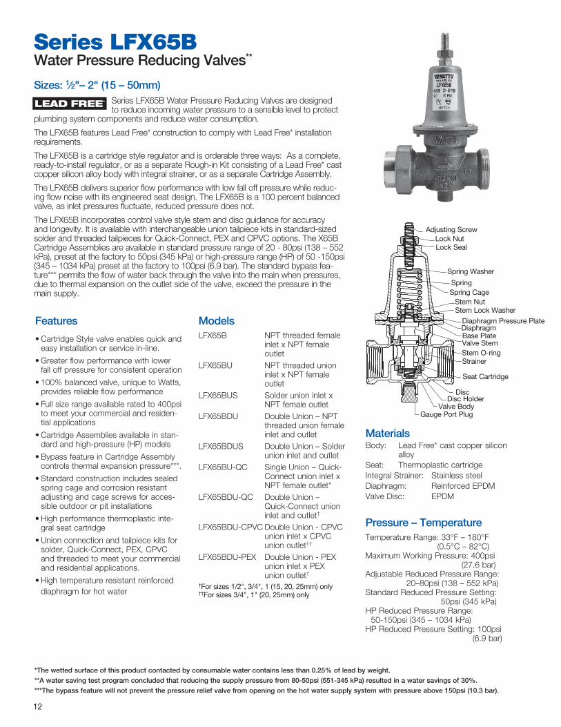
Features
• Cartridge Style valve enables quick and easy installation or service in-line.
• Greater flow performance with lower fall off pressure for consistent operation
• 100% balanced valve, unique to Watts, provides reliable flow performance
• Full size range available rated to 400psi to meet your commercial and residen-tial applications
• Cartridge Assemblies available in stan-dard and high-pressure (HP) models
• Bypass feature in Cartridge Assembly controls thermal expansion pressure***.
• Standard construction includes sealed spring cage and corrosion resistant adjusting and cage screws for acces-sible outdoor or pit installations
• High performance thermoplastic inte-gral seat cartridge
• Union connection and tailpiece kits for solder, Quick-Connect, PEX, CPVC and threaded to meet your commercial and residential applications.
• High temperature resistant reinforced diaphragm for hot water
ModelsLFX65B NPT threaded female
inlet x NPT female outlet
LFX65BU NPT threaded union inlet x NPT female outlet
LFX65BUS Solder union inlet x NPT female outlet
LFX65BDU Double Union – NPT threaded union female inlet and outlet
LFX65BDUS Double Union – Solder union inlet and outlet
LFX65BU-QC Single Union – Quick-Connect union inlet x NPT female outlet*
LFX65BDU-QC Double Union – Quick-Connect union inlet and outlet†
LFX65BDU-CPVC Double Union - CPVC union inlet x CPVC union outlet††
LFX65BDU-PEX Double Union - PEX union inlet x PEX union outlet†
†For sizes 1/2", 3/4", 1 (15, 20, 25mm) only††For sizes 3/4", 1" (20, 25mm) only
Series LFX65BWater Pressure Reducing Valves**
Sizes: 1⁄2"– 2" (15 – 50mm) Series LFX65B Water Pressure Reducing Valves are designed to reduce incoming water pressure to a sensible level to protect
plumbing system components and reduce water consumption.
The LFX65B features Lead Free* construction to comply with Lead Free* installation requirements.
The LFX65B is a cartridge style regulator and is orderable three ways: As a complete, ready-to-install regulator, or as a separate Rough-in Kit consisting of a Lead Free* cast copper silicon alloy body with integral strainer, or as a separate Cartridge Assembly.
The LFX65B delivers superior flow performance with low fall off pressure while reduc-ing flow noise with its engineered seat design. The LFX65B is a 100 percent balanced valve, as inlet pressures fluctuate, reduced pressure does not.
The LFX65B incorporates control valve style stem and disc guidance for accuracy and longevity. It is available with interchangeable union tailpiece kits in standard-sized solder and threaded tailpieces for Quick-Connect, PEX and CPVC options. The X65B Cartridge Assemblies are available in standard pressure range of 20 - 80psi (138 – 552 kPa), preset at the factory to 50psi (345 kPa) or high-pressure range (HP) of 50 -150psi (345 – 1034 kPa) preset at the factory to 100psi (6.9 bar). The standard bypass fea-ture*** permits the flow of water back through the valve into the main when pressures, due to thermal expansion on the outlet side of the valve, exceed the pressure in the main supply.
MaterialsBody: Lead Free* cast copper silicon
alloySeat: Thermoplastic cartridgeIntegral Strainer: Stainless steelDiaphragm: Reinforced EPDMValve Disc: EPDM
Pressure – TemperatureTemperature Range: 33°F – 180°F
(0.5°C – 82°C)Maximum Working Pressure: 400psi
(27.6 bar)Adjustable Reduced Pressure Range:
20–80psi (138 – 552 kPa)Standard Reduced Pressure Setting:
50psi (345 kPa)HP Reduced Pressure Range:
50-150psi (345 – 1034 kPa)HP Reduced Pressure Setting: 100psi
(6.9 bar)
Adjusting ScrewLock NutLock Seal
Spring Washer
SpringSpring Cage
Stem NutStem Lock Washer
Diaphragm Pressure PlateDiaphragmBase PlateValve StemStem O-ringStrainer
Seat Cartridge
DiscDisc Holder
Valve BodyGauge Port Plug
* The wetted surface of this product contacted by consumable water contains less than 0.25% of lead by weight.
**A water saving test program concluded that reducing the supply pressure from 80-50psi (551-345 kPa) resulted in a water savings of 30%.
*** The bypass feature will not prevent the pressure relief valve from opening on the hot water supply system with pressure above 150psi (10.3 bar).
LEAD FREE*

For additional information, reference literature ES-LFX65B . 13
Standards Certified to ASSE Standard 1003, and
listed by ASSE and IAMPO.
Dimensions –– Weights
Capacity
F
EA
D
C
B
Red
uced
Pre
ssur
e D
rop
kPa psi
0 0
14 2
28 4
41 6
55 8
69 10
83 12
96 14
110 16
124 18
138 20
Sizes 1⁄2", 3⁄4", 1" (15, 20, 25mm)
0 5 10 15 20 25 30 gpm 0 79 38 57 76 95 114 lpm
(25mm)
(20mm)(15mm)
kPa psi 0 0 14 2 28 4 41 6 55 8
69 10
83 12
96 14
110 16
124 18
138 20
Red
uced
Pre
ssur
e D
rop
Sizes 11⁄4", 11⁄2", 2" (32, 40, 50mm)
0 20 40 60 80 100 120 140 gpm 0 76 151 227 303 379 454 530 lpm
(50mm)
(40mm)
(32mm)
SIZE (Dn) DImEnSIOnS WEIgHTS
A B (MAX) STD B (MAX) HP C D (DIA) E (Threaded) E (Sweat) E (QC) F (Threaded) F (Sweat) F (QC)in. mm in. mm in. mm in. mm in. mm in. mm in. mm in. mm in. mm in. mm in. mm in. mm lbs. kgs.1⁄2 15 3 76.7 57⁄16 137.7 611⁄16 169.9 15⁄16 32.8 27⁄16 61.2 311⁄16 93.0 35⁄8 91.9 41⁄2 115 45⁄16 109.2 41⁄4 107.2 6 153 1.43 0.653⁄4 20 31⁄8 79.8 57⁄16 137.7 611⁄16 169.9 15⁄16 32.8 27⁄16 61.2 33⁄4 96.0 4 101.1 413⁄16 122 47⁄16 112.3 413⁄16 122.4 61⁄2 165 1.52 0.691 25 39⁄16 90.4 63⁄16 157.2 714⁄16 199.9 13⁄8 34.5 23⁄4 70.6 415⁄16 110.2 49⁄16 116.1 55⁄16 135 51⁄8 130.0 59⁄16 141.7 71⁄16 179 2.22 1.01
11⁄4 32 45⁄16 110.2 615⁄16 176.0 913⁄16 248.9 19⁄16 39.40 31⁄4 81.8 55⁄8 142.7 53⁄8 136.9 – – 67⁄8 175.3 67⁄16 163.6 – – 3.61 1.6411⁄2 40 51⁄2 140.2 113⁄4 297.9 163⁄4 426.0 17⁄8 47.50 49⁄16 115.8 613⁄16 142.7 611⁄16 169.9 – – 81⁄16 205.2 77⁄8 199.6 – – 9.27 4.202 50 51⁄2 140.2 113⁄4 297.9 163⁄4 426.0 17⁄8 47.50 49⁄16 115.8 613⁄16 173.5 615⁄16 176.5 – – 81⁄8 206.8 83⁄8 212.9 – – 9.59 4.35
Optionsadd Suffix:
G Gauge tapping, 1⁄4" (8mm)GG Gauge tapping and 160psi
(11.0 bar) gaugeHP High pressure range 50–150psi
(3.4 – 10.3 bar)LP Low pressure range 10-15 psi

Series LFN45B-M1Water Pressure Reducing Valves**
Sizes: 3⁄4" – 1" (20 – 25mm)Series LFN45B-M1 Water Pressure Reducing Valves are designed to reduce incoming water pressure to a sensible
level to protect plumbing system components and reduce water consumption. The LFN45B features Lead Free* construction to comply with Lead Free* installation requirements. This series is suitable for water supply pressures up to 400psi (27.6 bar) and may be adjusted from 25 – 75psi (172 – 517 kPa). The standard setting is 50psi (345 kPa). All parts are quickly and easily serviceable without removing the valve from the line. The standard bypass feature*** permits the flow of water back through the valve into the main when pressures, due to thermal expansion on the outlet side of the valve, exceed the pressure in the main supply.
Features
• Double union inlet & outlet connections (option DU)
• Integral stainless steel strainer
• Thermoplastic seat & cage
• Lead Free* cast copper silicon alloy body construction
• Serviceable in line
• Bypass feature controls thermal expansion pressure***
• Sealed spring cage on all models for accessible outdoor or pit installations
ModelsLFN45B-M1 NPT threaded female
inlet x NPT female out-let
LFN45BU-M1 NPT threaded union inlet x NPT female out-let
LFN45BU-S-M1 Solder union inlet x NPT female outlet
LFN45BU-QC-M1 Single Union – QC union inlet
LFN45BDU-M1 Double Union – NPT threaded union female inlet and outlet
LFN45BDU-S-M1 Double Union – Solder union inlet and outletLFN45BDU-PEX-M1 Double Union – PEX
union inlet and outlet (3⁄4" and 1" only)
LFN45BDU-CPVC-M1 Double Union – CPVC
union inlet and outlet (3⁄4" and 1" only)
LFN45BDU-QC-M1 Double Union – QC
union inlet and outlet (3⁄4" and 1" only)
Options
add Suffix:G Gauge tappingGG Gauge tapping and 160psi
(11.0 bar) gauge
Pressure – TemperatureTemperature Range: 33°F – 180°F
(0.5°C – 82°C)Maximum Working Pressure: 400psi
(27.6 bar)Adjustable Reduced Pressure Range:
25 – 75psi (172 – 517 kpa)Standard Reduced Pressure Setting:
50psi (345 kpa)
StandardsMeets requirements of ASSE Standard
1003; (ANSI A112.26.2) andCSA Standard B356. Certified by NSF
to ANSI/NSF Standard 61 Annex G. Listed by IAPMO and City of Los Angeles.
14
Integral stainless steel strainer
Thermoplastic seatThermal expan-sion bypass
Threaded, solder PEX or CPVC ends
Reinforced diaphragm
* The wetted surface of this product contacted by consumable water contains less than 0.25% of lead by weight.
**A water saving test program concluded that reducing the supply pressure from 80-50psi (551-345 kPa) resulted in a water savings of 30%.
*** The bypass feature will not prevent the pressure relief valve from opening on the hot water supply system with pressure above 150psi (10.3 bar).
LEAD FREE*

A + E + E
C
D
g A + EA
ABOVE VALVE SHOWN WITH SINGLE NPT UNION CONNECTION ON INLET
VALVES MAY BE ORDERED WITH 0,1,OR 2 UNION CONNECTIONS USING ANY COMBINATION OF NPT, SOLDER, PEX OR CPVC CONNECTIONS REQUIRED
“F" DIMENSIONS ARE APPROXIMATE ENGAGEMENT LENGTHS.
FEmAlE nPT THREADBOTH EnDS OF BODy
FSWEAT
ESWEAT
FCPVC
EPEX
FPEX
ECPVC
FnPT
EnPT
For additional information, reference literature ES-LFN45B . 15
Dimensions –– Weights
Capacity
kPa psi
0 0
34.5 5
68.9 10
103.4 15
137.8 20
172.3 25
0 10 20 30 40 gpm0 37.3 75.7 113.6 151.4 lpm
Pres
sure
Dro
p
Flow
EqC
FqC
SIZE (Dn) DImEnSIOnS WEIgHT
A C D ENPT ESWEAT EPEX ECPVC EQC FNPT FSWEAT FPEX FCPVC FQC Gin. mm in. mm in. mm in. mm in. mm in. mm in. mm in. mm in. mm in. mm in. mm in. mm in. mm in. mm in. mm lbs. kgs.3⁄4 20 37⁄16 88 49⁄16 116 111⁄16 43 5⁄8 16 7⁄8 21 15⁄16 24 13⁄16 21 19⁄16 40 9⁄16 14 3⁄4 19 5⁄8 16 3⁄4 18 111⁄16 42 21⁄4 57 2 .911 25 41⁄8 105 49⁄16 116 111⁄16 43 3⁄4 20 1 26 11⁄8 29 11⁄16 26 111⁄16 43 11⁄16 17 15⁄16 23 13⁄16 21 15⁄16 23 13⁄4 45 21⁄4 57 3 1.36

16
Sizes: 3⁄4" – 1" (20 – 25mm)Series LFN45B-EZ Water Pressure Reducing Valves are designed to reduce incoming water pressure to a sensible
level to protect plumbing system components and reduce water consumption. This series is suitable for water supply pressures up to 400psi (27.6 bar) and may be adjusted from 25 – 75psi (172 – 517 kPa). The standard setting is 50psi (345 kPa). All parts are quickly and easily serviceable without removing the valve from the line. The standard bypass feature*** permits the flow of water back through the valve into the main when pressures, due to thermal expansion on the outlet side of the valve, exceed the pressure in the main supply. The LFN45-B-EZ features Lead Free* construction to comply with Lead Free* installation requirements.
Features
• Factory calibrated outlet pressure adjustment
• Easily adjustable pressure setting
• Double union inlet & outlet connections (option DU)
• Integral stainless steel strainer
• Thermoplastic cage & seat
• Lead Free* copper silicon alloy body construction
• Serviceable in line
• Bypass feature controls thermal expan-sion pressure***
MaterialsBody: Lead Free* Cast Copper Silicon AlloySeat: ThermoplasticCage: ThermoplasticIntegral Strainer: Stainless steelDiaphragm: Reinforced EPDMValve Disc: Elastomer
ModelsLFN45B-EZ-M1 NPT threaded female
inlet x NPT female outlet
LFN45BU-EZ-M1 NPT threaded union inlet x NPT female outlet
LFN45BU-EZ-S-M1 Solder union inlet x
NPT female outletLFN45BDU-EZ-M1 Double Union – NPT
threaded union female inlet and outlet
LFN45BDU-EZ-S-M1 Double Union – Solder
union inlet and outletLFN45BDU-EZ-PEX-M1 Double Union – PEX
union inlet and outletLFN45BDU-EZ-CPVC-M1 Double Union – CPVC
union inlet and outlet
Options
add Suffix:G Gauge tappingGG Gauge tapping and 160psi (11 bar)
gauge
Pressure – TemperatureTemperature Range: 33°F – 180°F
(0.5°C – 82°C)Maximum Working Pressure: 400psi
(27.6 bar)Adjustable Reduced Pressure Range:
25-75psi (172 - 517kPa)Standard Reduced Pressure Setting:
50psi (345kPa)
Standards Meets requirements of ASSE Standard
1003; (ANSI A112.26.2); CSA Standard B356; and listed by IAPMO.
Integral Stainless Steel Strainer
Thermoplastic SeatThermal Expansion Bypass
Threaded, Solder, PEX or CPVC ends
ReinforcedDiaphragm
* The wetted surface of this product contacted by consumable water contains less than 0.25% of lead by weight.
**A water saving test program concluded that reducing the supply pressure from 80-50psi (551-345 kPa) resulted in a water savings of 30%.
*** The bypass feature will not prevent the pressure relief valve from opening on the hot water supply system with pressure above 150psi (10.3 bar).
LEAD FREE*
Series LFN45B - EZWater Pressure Reducing Valves**

A + E + E
C
D
g A + EA
ABOVE VALVE SHOWN WITH SINGLE NPT UNION CONNECTION ON INLET
VALVES MAY BE ORDERED WITH 0,1,OR 2 UNION CONNECTIONS USING ANY COMBINATION OF NPT, SOLDER, PEX OR CPVC CONNECTIONS REQUIRED
“F" DIMENSIONS ARE APPROXIMATE ENGAGEMENT LENGTHS.
FEmAlE nPT THREADBOTH EnDS OF BODy
For additional information, reference literature ES-LFN45B-EZ . 17
Dimensions –– Weights
Capacity
kPa psi
0 0
34.5 5
68.9 10
103.4 15
137.8 20
172.3 25
0 10 20 30 40 gpm0 37.3 75.7 113.6 151.4 lpm
Pres
sure
Dro
p
Flow
FSWEAT
ESWEAT
EPEX
FPEX
ECPVC
FnPT
EnPT
FCPVC
SIZE (Dn) DImEnSIOnS WEIgHT
A C D ENPT ESWEAT EPEX ECPVC FNPT FSWEAT FPEX FCPVC Gin. mm in. mm in. mm in. mm in. mm in. mm in. mm in. mm in. mm in. mm in. mm in. mm in. mm lbs kg3⁄4 20 37⁄16 88 43⁄8 111 111⁄16 43 5⁄8 16 7⁄8 21 15⁄16 24 13⁄16 21 9⁄16 14 3⁄4 19 5⁄8 16 3⁄4 18 21⁄4 57 1.75 .791 25 41⁄8 105 43⁄8 111 111⁄16 43 3⁄4 20 1 26 11⁄8 29 11⁄16 26 11⁄16 17 15⁄16 23 13⁄16 21 15⁄16 23 21⁄4 57 2 .91

18
Series LF223, LF223SHigh Capacity Water Pressure Reducing Valves**
Sizes: 1⁄2" – 21⁄2" (15 – 65mm)Series LF223 and LF223S High Capacity Water Pressure Reducing Valves are designed to reduce incoming water pres-
sure to a sensible level to protect plumbing system components and reduce water consumption. The LF223/LF223S features Lead Free* construction to comply with Lead Free* installation requirements. This series is suitable for water supply pressures up to 300psi (20.7 bar) and may be adjusted from 25 – 75psi (172 – 517 kPa). The standard setting is 50psi (345 kPa). Series LF223 features an enlarged diaphragm, spring cage and seat orifice for high capacity performance. Series LF223S has the same options as the LF223, except it is furnished with a strainer. All parts are quickly and easily serviceable without removing the valve from the line. The optional bypass feature*** permits the flow of water back through the valve into the main when pres-sures, due to thermal expansion on the outlet side of the valve, exceed the pressure in the main supply.
High temperature-resisting diaphragm
for hot or cold water
Disc holder removable for replacement of disc without dismantling the valve - no special tools required
Light Stainless steel perforated strainer
screen
Replaceable stainless seat
Lead Free* brass construction 1⁄2" – 2"
Sensitive spring and large diaphragm area for accurate pressure control
Sealed spring cage
Features
• Enlarged diaphragm, spring cage and seat orifice for super capacity perfor-mance
• Lead Free* brass body construction (except 21⁄2" (65mm) which is iron)
• Serviceable in line
• Series LF223S furnished with separate strainer
• Optional bypass feature controls ther-mal expansion pressure***
• Sealed spring cage on all models for accessible outdoor or pit
ModelsLF223 NPT threaded female inlet x
NPT threaded female outletLF223-S
NPT threaded female inlet with strainer x NPT threaded female outlet
For 21⁄2" – 3" (65 – 80mm) bronze threaded valves, refer to literature ES-LFN223B.For 3" (80mm) flanged connections, refer to literature ES-LFN223F.
Optionsadd Suffix:B Built in bypass featureLP Low pressure range 10-35psi
(69 – 241 kPa)HP High pressure range, reduced
range shown below:
Available with or without separate strainer
* The wetted surface of this product contacted by consumable water contains less than 0.25% of lead by weight.
**A water saving test program concluded that reducing the supply pressure from 80-50psi (551-345 kPa) resulted in a water savings of 30%.
*** The bypass feature will not prevent the pressure relief valve from opening on the hot water supply system with pressure above 150psi (10.3 bar).
LEAD FREE*
REDuCED PRESSuRE RAngE - SuFFIX HP
Size Rangein. mm psi bar 1⁄2 15 50-145 3.52-10.19 3⁄4 20 50-145 3.52-10.19 1 25 50-145 3.52-10.19
11⁄4 32 50-120 3.52-8.44 11⁄2 40 50-95 3.52-6.68 2 50 50-95 3.52-6.68
21⁄2 65 50-95 3.52-6.68

MaterialsBody: 1⁄2" – 2" (15 – 50mm) Lead Free*
Brass 21⁄2" (65mm) IronSeat: Replaceable stainless steelStrainer Screen: Stainless steel (Model
LF223S)Diaphragm: Reinforced Buna-NValve Disc: EPDM
Pressure – TemperatureTemperature Range: 33°F – 160°F
(0.5°C – 71°C)Maximum Working Pressure: 300psi
(20.7 bar)Adjustable Reduced Pressure Range:
25-75psi (172 – 517 kPa)Standard Reduced Pressure Setting:
50psi (345 kPa)
Standards 1⁄2" – 2"
(15 – 50mm) meets requirements of ASSE Standard 1003; (ANSI A112.26); CSA Standard B356; Southern Standard Plumbing Code, Military Standard MIL-V-18146B and listed by IAPMO.
For additional information, reference literature ES-LF223 . 19
Dimensions –– Weights
As
n
A
C
D
Capacity
Sizes 1⁄2", 3⁄4", 1" (15, 20, 25mm)
1⁄2"
3⁄4"
1"
223
0
10
20
30
40
50
60
70
80
0 5 10 15 20 PRESSURE FALL OFF - PSI
223
0
50
100
150
200
0 5 10 15 20 25 30PRESSURE FALL OFF - PSI
lpm gpm
304 80
266 70
227 60
190 50
151 40
114 30
76 20
38 10
0 00 5 10 15 20 psi0 34 69 103 138 kPa
Flow
Pressure Drop
11⁄2"
11⁄4"
2"
21⁄2"
Sizes 11⁄4", 11⁄2", 2", 21⁄2" (32, 40, 50, 65mm)
223
0
10
20
30
40
50
60
70
80
0 5 10 15 20 PRESSURE FALL OFF - PSI
223
0
50
100
150
200
0 5 10 15 20 25 30PRESSURE FALL OFF - PSI
lpm gpm 950 250
760 200
570 150
379 100
190 50
0 00 5 10 15 20 25 30 psi0 34 69 103 138 172 207 kPa
Flow
Pressure Drop
SIZE (Dn) DImEnSIOnS WEIgHT
A (LF223) As (LF223S) C D N (LF223S) LF223 LF223Sin. mm in. mm in. mm in. mm in. mm in. mm lbs. kgs. lbs. kgs.1⁄2 15 41⁄4 108 9 229 61⁄4 159 2 50 21⁄2 64 4.5 2.0 6 2.73⁄4 20 41⁄4 108 9 229 61⁄4 159 2 50 21⁄2 64 5 2.3 6.5 2.91 25 43⁄4 121 1015⁄16 262 61⁄2 165 21⁄8 54 215⁄ 16 75 7 3.2 9.5 4.3
11⁄4 32 5 127 1115⁄16 287 63⁄4 172 23⁄4 70 3 76 9 4.1 12 5.411⁄2 40 63⁄4 171 143⁄4 375 97⁄8 251 23⁄4 70 37⁄16 87 19.5 8.8 23.5 10.72 50 8 203 163⁄4 425 103⁄4 273 33⁄8 86 4 102 30 13.6 37.5 17.0
21⁄2 65 9 229 201⁄8 511 103⁄4 273 33⁄8 86 5 127 32.5 14.8 59 26.8
REDuCED PRESSuRE RAngE - SuFFIX HP
Size Rangein. mm psi bar 1⁄2 15 50-145 3.52-10.19 3⁄4 20 50-145 3.52-10.19 1 25 50-145 3.52-10.19
11⁄4 32 50-120 3.52-8.44 11⁄2 40 50-95 3.52-6.68 2 50 50-95 3.52-6.68
21⁄2 65 50-95 3.52-6.68

20
Series LFN223B, LFN223BSSuper Capacity Water Pressure Reducing Valves**
Sizes: 21⁄2" – 3" (65 – 80mm)Series LFN223B and LFN223BS Super Capacity Water Pressure Reducing Valves are designed to reduce incoming
water pressure to a sensible level to protect plumbing system components and reduce water consumption. The LFN223B/LFN223BS features Lead Free* con-struction to comply with Lead Free* installation requirements. This series is suitable for water supply pressures up to 300psi (20.7 bar) and may be adjusted from 25 – 75psi (172 – 517 kPa). The standard setting is 50psi (345 kPa). Series LFN223B features an enlarged diaphragm, spring cage and seat orifice for super capacity performance. Series LFN223BS has the same options as the LFN223B, except it is furnished with a Lead Free* strainer. All parts are quickly and easily serviceable without removing the valve from the line. The standard bypass feature*** permits the flow of water back through the valve into the main when pressures, due to thermal expansion on the outlet side of the valve, exceed the pressure in the main supply.
Features
• Enlarged diaphragm, spring cage and seat orifice for super capacity performance
• Lead Free* cast copper silicon alloy body construction
• Serviceable in line
• Series LFN223BS furnished with separate Lead Free* strainer
• Standard bypass feature controls thermal expansion pressure***
• Sealed spring cage on all models for accessible outdoor or pit installations
Models21⁄2" LFN223M2-B NPT threaded female inlet
x NPT threaded female outlet
3" LFN223M1-B NPT threaded female inlet x
NPT threaded female outlet21⁄2" LFN223M2-BS NPT threaded female inlet
with strainer x NPT threaded female outlet
3" LFN223M1-BS NPT threaded female inlet
with strainer x NPT threaded female outlet
For 1⁄2" – 21⁄2" threaded connections, refer to literature ES-LF223.For 3" flanged connections, refer to litera-ture ES-LF223F.
Optionsadd Suffix:HP High pressure range 75 – 125psi
(172 – 862 kPa)21⁄2" HP, LP, G and GG options3" HP option
MaterialsBody: Lead Free* cast copper silicon
alloy Seat: Replaceable stainless steel alloyStrainer Screen: Stainless steel (model
LFN223S)Diaphragm: Reinforced Buna-NValve Disc: EPDM
* The wetted surface of this product contacted by consumable water contains less than 0.25% of lead by weight.
**A water saving test program concluded that reducing the supply pressure from 80-50psi (551-345 kPa) resulted in a water savings of 30%.
*** The bypass feature will not prevent the pressure relief valve from opening on the hot water supply system with pressure above 150psi (10.3 bar).
LEAD FREE*
Disc holder removable for replacement of disc without dismantling the valve — no special tools required.
Sensitive spring and large diaphragm area for accurate pressure control
lead Free*body construction
Renewable stainless steel
alloy seat
large stainless steel perforated strainer screen
Sealed spring cage
Bypass

For additional information, reference literature ES-LFN223B . 21
Capacity
Dimensions –– Weights
A
n
l
C
D
21⁄2" 3"
Redu
ced
Pres
sure
Fal
l-Off
Flow
kPa psi 345 50
276 40
207 30
138 20 121 17.5 103 15 86 12.5 69 10 52 7.5 34 5 17 2.5 0 0
40 80 120 160 200 240 320 400 480 560 640 720 gpm152 304 456 608 760 912 1216 1520 1824 2128 2432 2736 lpm
SIZE (Dn) DImEnSIOnS (APPROX.) WEIgHT
A (LFN223BS) C D L N (LFN223BS) LFN223B LFN223BSIn. mm In. mm In. mm In. mm In. mm In. mm lbs. kgs. lbs. kgs.21⁄2 65 17 432 103⁄4 273 27⁄8 73 77⁄8 200 5 127 30 13.6 44 20.03 80 203⁄4 527 123⁄4 324 41⁄8 105 101⁄2 267 63⁄4 172 71 32.2 95 43.0
Pressure – TemperatureTemperature Range: 33°F – 160°F
(0.5°C – 71°C)Maximum Working Pressure: 300psi
(20.7 bar)Adjustable Reduced Pressure Range:
25 – 75psi (172 – 517 kPa)Standard Reduced Pressure Setting:
50psi (345 kPa)
Standards Both 21⁄2" and 3"
are listed to ASSE 1003 through IAPMO (UPC).
The 21⁄2" is also listed to ASSE 1003 through ASSE.
Both 21⁄2" and 3" are listed to NSF 61-G

22
Size: 3" (80mm)Series LFN223F and LFN223FS Super Capacity Water Pressure Reducing Valves are designed to reduce incoming water pres-
sure to a sensible level to protect plumbing system components and reduce water consumption. This series is suitable for water supply pressures up to 175psi (12.1 bar) and may be adjusted from 25 – 75psi (172 – 517 kPa). The standard setting is 50psi (345 kPa). Series LFN223F features an enlarged diaphragm, spring cage and seat orifice for super capacity performance. These valves also contain a semibalanced piston feature to assure rapid response to reduced pressure changes as well as to provide maximum flow with minor pressure drop. Series LFN223FS has the same options as the LFN223F, except it is furnished with a strainer. All parts are quickly and easily serviceable without removing the valve from the line.
Features• Enlarged diaphragm, spring cage and
seat orifice for super capacity perfor-mance
• Iron body construction• Stainless steel piston• Series LFN223FS furnished with sepa-
rate strainer• Sealed spring cage on all models for
accessible outdoor or pit installations
ModelsLFN223F Flanged inlet x Flanged outletLFN223FS Flanged inlet x Flanged outlet
with strainer
MaterialsBody: Iron coated with corrosion-
resistant cold galvanizingSeat: Replaceable stainless steelDiaphragm: Reinforced Buna-NDisc: EPDMPiston: Stainless steel
Pressure – TemperatureTemperature Range: 33°F – 160°F (0.5°C – 71°C)Maximum Working Pressure: 175psi (12.1 bar)Adjustable Reduced Pressure Range: 25 – 75psi (172 – 517 kPa)Standard Reduced Pressure Setting: 50psi (345 kPa)
Optionsadd Suffix:WR 3⁄4" (20mm) Model LF223 auxiliary
regulator (piping not included)S Strainer
(See ES-77F-DI-125 for details)
Series LFN223F, LFN223FSFlanged Super Capacity Water Pressure Reducing Valves**
* The wetted surface of this product contacted by consumable water contains less than 0.25% of lead by weight.
**A water saving test program concluded that reducing the supply pressure from 80-50psi (551-345 kPa) resulted in a water savings of 30%.
*** The bypass feature will not prevent the pressure relief valve from opening on the hot water supply system with pressure above 150psi (10.3 bar).
All parts easily serviceable for quick maintenance .
Sensitive spring and large diaphragm are for accurate pressure control .
3⁄4" (20mm) tapping for auxiliary regulator
Sealed cage
High temperature-resisting nylon- reinforced diaphragm .
Iron body of valve is coated
with special corrosion
preventative type of cold galvanizing .
Renewable stainless
steel seat
LEAD FREE*

For additional information, reference literature ES-LFN223F . 23
Capacity
Option WR
Dimensions –– Weights
m
n
A
l
AS
C
D
Redu
ced
Pres
sure
Fal
l-Off
Flow
kPa psi 138 20
103 15
69 10
34 5
0 0 40 80 120 160 200 gpm 152 304 456 608 760 lpm
High Pressure
3⁄4" (20mm) LF223 regulator to handle low demands .
Set 10psi (68 kPa) higher than LFN223F .
Piping not provided
Reduced Pressure
3" (80mm) LFN223F
mODEl nO. SIZE (Dn) DImEnSIOnS WEIgHT
A AS C D L M Nin. mm in. mm in. mm in. mm in. mm in. mm in. mm in. mm lbs. kgs.
LFN223F 3 80 121⁄2 318 — — 141⁄2 368 33⁄4 95 71⁄2 191 — — — — 86 39LFN223FS 3 80 121⁄2 318 225⁄8 575 141⁄2 368 33⁄4 95 71⁄2 191 101⁄8 257 7 178 120 54

Features
• Lead Free* body construction
• Replaceable stainless steel seat
• Outstanding maintenance features
• Close control of reduced pressure
• High temperature-resisting diaphragm
• Interchangeable diaphragm chamber
MaterialsBody: LF127W: Lead Free* cast cop-
per silicon alloy LFF127W: Iron
Seat: Replaceable stainless steelStem: Stainless steel
Pressure – TemperatureTemperature Range: 33˚F – 160˚F
(0.5˚C – 71˚C)Maximum Working Pressure: 175psi
(12.1 bar)Adjustable Reduced Pressure Range:
25 – 100psi (17 – 690 kPa))
Options (4" F127W only)add Suffix:
WR 3⁄4" (20mm) Model 223 auxiliary regulator. (Piping not included)
24
Model LF127W and LFF127W High Capacity Water Pressure Reducing Valves
are designed to reduce incoming water pressure to a sensible level to protect plumbing system components and reduce water consumption. The LF127W and LFF127W are remote control type regulators ideal for commercial and industrial applications where a regulator must reach full capacity with a minor drop in reduced pressure. These models are also suitable for applications where close pressure regulation is required through extensive volume demand. These models are suitable for water supply pressures up to 175psi (12.1 bar) and may be adjusted from 25 – 100psi (172 – 690 kPa). All parts are quickly and easily service-able.
The LF127W and LFF127W feature Lead Free* construction to comply with Lead Free* installation requirements.
High temperature- resisting diaphragm
Valve disc can be quickly replaced
Replaceable stain-less steel seat
Stainless steel stem
Tapping provided in low pressure side of body to per-mit convenient, economical attachment of equalizer line
Diaphragm chamber is easily changed by the remov-al of two cap screwsRequirements of various
pressure conditions can be quickly met by
interchanging the various sizes of diaphragm
chambers - 6", 8", 10" (150, 178, 200mm) as well as by interchanging spring
Model LF127W and LFF127WHigh Capacity Water Pressure Reducing Valve
Sizes: 3" – 4" (80 – 100mm)
4" (100mm) lFF127W with Flanged Ends
3" (80mm) lF127W with Threaded Ends
Equalizer line(not furnished)
6", 8" or 10" (150, 178, or 200mm) depending
upon reduced pressure range .
High Pressure
3⁄4" (20mm) 223 regulator to handle low demands.
Set 10psi (68 kPa) higher than lFF127W.
Piping not provided
Reduced Pressure
4" lFF127Wneedle Valve
* The wetted surface of this product contacted by consumable water contains less than 0.25% of lead by weight.
*** The bypass feature will not prevent the pressure relief valve from opening on the hot water supply system with pressure above 150psi (10.3 bar).
LEAD FREE*

For additional information, reference literature ES-LF127W . 25
Capacity
Dimensions –– Weights
kPa psi
138 20
103 15
69 10
34 5
0 00 50 100 150 200 250 300 gpm
0 190 380 570 760 246 1140 lpm
Pres
sure
Dro
p
Flow
SIZE DImEnSIOnS WEIgHT
Connection A B C Din. in. mm in. mm in. mm in. mm lbs. kgs.3 threaded 8 203 161⁄8 410 22⁄5 70 23⁄8 60 40 183 flanged 8 203 161⁄8 410 37⁄10 93 33⁄4 95 42 194 flanged 121⁄8 308 161⁄8 410 23⁄10 59 41⁄2 114 84 38
B
D
A
C

26 For additional information, reference literature ES-2300 .
Series 2300Direct Operated Water Pressure Reducing Valves
Sizes: 3" – 6" (80 – 150mm)
Features
• An essentially balanced single seat minimizes variation in delivery pressure resulting from varying inlet pressure
• A large Hycar diaphragm ensures a sensitive response to the slightest changes in reduced pressure
• Packless design eliminates stuffing box friction
• Hycar composition single seat pro-vides for dead-end shutoff and pre-vents pressure-creep when no flow is required
• Self-aligning design. Eliminates the need for a stem guide in the bottom flanges and removes a point of direct collection that can cause faulty opera-tion
• Disc and piston are located to minimize the possibility of obstruction by dirt
• Large pressure plate gives ample sup-port to the diaphragm – assuring long life
• Self-contained design, requires no con-trol lines
• All internal parts accessible by remov-ing blind flange or spring chamber. Regular maintenance can be per-formed with the valve body in line
• No stuffing box maintenance required
MaterialsBody: Cast IronDisc: Hycar CompositionTrim: Stainless SteelDiaphragm: HycarSpring: Tempered Steel
Applications
• Industrial plants for washrooms and processing operations
• Apartment buildings, hotels, office buildings and hospitals to provide each floor with a steady pressure.
• Municipal or plant water main to main-tain constant pressure
Pressure – TemperatureMaximum Temperature: 150°F (66°C)Maximum Pressure: 200psi (13.8 bar)Reduced Pressure Range: 30 – 80psi (207 – 552 kPa)
Typical Applications Washroom Water SupplySeries 2300 is a direct operated, bal-anced, tight seating pressure reducing valve, opened and closed by small varia-tions in delivery pressure.
A large Hycar dia-phragm ensures a sensitive response to the slightest change in reduced pressure
This design being self-contained, no control lines are required
Designed to close against the flow . Will not chatter or pro-duce water hammer . Operates smoothly and quietly
The design of this valve minimizes
any danger of dirt lodging in the stem
guide
Essentially bal-anced single
seat minimizes a variation in delivery
pressure resulting from a varying inlet
pressure
No stem guide in bottom flange to collect dirt . These valves are self-aligning and the guiding of the disc is independent of the bolted bottom flange .
Series 2300
* The wetted surface of this product contacted by consumable water contains less than 0.25% of lead by weight.
LEAD FREE* Series 2300 Direct Operated Water Pressure Reducing Valves are designed for dead-end water service where the flow is intermittent and changes rapidly, as on domestic water system. Series 2300 is also installed to regulate the flow of water to such fast acting equipment as flushometers and snap cocks. The Series 2300 is recommended where city water pressure is to be reduced to supply plumbing fixtures to prevent violent pressure fluctuations. The 2300 features Lead Free* construction to comply with Lead Free* installation requirements.

For additional information, reference literature C-CACV . 27
Series 115 (Globe), 1115 (Angle)Water Pressure Reducing Automatic Control Valves
Sizes: 11⁄4" – 16" (32 – 400mm)
Series 115 (Globe) and 1115 (Angle) Water Pressure Reducing Automatic Control Valves auto-matically reduce a higher inlet pressure to a constant lower outlet pressure regardless of changing flow rates and or varying inlet pressure.
Features
• Wide range of sizes available 11⁄4" – 16"
• 100% Fused epoxy coating inside and out (FDA and NSF approved, meets AWWA standards)
• Exclusive “Quad Sea” provides positive drip-tight closure and longer valve lifes-pan
• Diaphragm actuated (one-moving part)• Hydraulically operated (frictionless)• Top and bottom guided stem• Packless construction
(less-maintenance)
Models115 (Globe)/1115 (Angle) –
Pressure Reducing115-2 (Globe)/1115-2 (Angle) –
Pressure Reducing/Sustaining115-3 (Globe)/1115-3 (Angle) –
Pressure Reducing/Check115-4 (Globe)/1115-4 (Angle) –
Pressure Reducing/Solenoid On-Off115-7 (Globe)/1115-7 (Angle) –
Pressure Reducing/Surge115-74 (Globe)/1115-74 (Angle) –
Pressure Reducing/Low Flow Bypass Valve
Standard Components
3" and Smaller• Flo-Clean pilot circuit strainer• Adjustable opening speed control• Fixed orifice supply restriction• 20 – 175psi downstream adjustment
range
4" and Larger• Y-pattern pilot circuit strainer• Pilot circuit isolation ball valves• Fixed orifice supply restriction• 20 – 175psi downstream adjustment
range
Optional ComponentsAdjustable opening speed control
4" and largerPilot circuit isolation ball valves
3" and smallerY-Pattern pilot circuit strainer
3" and smallerAdjustable closing speed control (all sizes)Position indicator (all sizes)Inlet and outlet pressure gauges (all sizes)
Pressure-TemperatureAdjustable Reduced Pressure Range:
20-175psi (1.3 – 12 bar)Optional Reduced Pressure Settings:
0-30psi (0 – 2 bar), 100-300psi (6.8 – 20 bar)

28 For additional information, reference literature ES-LFN250 .
Series LFN250Iron Body Water PressureReducing Valves**
Sizes: 1⁄2" – 3⁄4" (15 – 20mm)Series LFN250 Iron Body Water Pressure Reducing Valves are designed to reduce incoming water pressure to a sensible
level to protect plumbing system components and reduce water consumption. This series is suitable for water supply pressures up to 250psi (17.2 bar) and may be adjusted from 25 – 75psi (172 – 517 kPa). The standard setting is 50psi (345 kPa). All parts are quickly and easily serviceable without removing the valve from the line. The optional bypass feature*** permits the flow of water back through the valve into the main when pressures, due to thermal expansion on the outlet side of the valve, exceed the pressure in the main supply. The LFN250 features Lead Free* construc-tion to comply with Lead Free* installation requirements.
Features
• Integral strainer
• Unitized construction for ease of maintenance
• High temperature resisting diaphragm for hot or cold water
• All working parts easily and quickly serviceable without removing the valve from the line
• Optional bypass feature*** controls thermal expansion pressure
Models
ModelsLFN250 – NPT threaded female inlet x
NPT female outletLFN250B – NPT threaded female inlet
x NPT female outlet with thermal expansion bypass feature
Note: Cast iron body regulators are not intended for buried or pit services.
MaterialsBody: Iron Seat: Stainless steelIntegral Strainer: Stainless steelStem: Lead Free* brassDisc: Lead Free* brass
Pressure — TemperatureTemperature Range: 33°F – 160°F (0.5°C – 71°C)Maximum Working Pressure: 250psi (17.2 bar)Adjustable Reduced Pressure Range: 25 – 75psi (172 – 517 kPa)Standard Reduced Pressure Setting: 50psi (345 kPa)
* The wetted surface of this product contacted by consumable water contains less than 0.25% of lead by weight.
**A water saving test program concluded that reducing the supply pressure from 80-50psi (551-345 kPa) resulted in a water savings of 30%.
*** The bypass feature will not prevent the pressure relief valve from opening on the hot water supply system with pressure above 150psi (10.3 bar).
LEAD FREE*

For additional information, reference literature ES-LF26A/263A . 29
Dimensions – Weights
Series LF26A, LF263ASmall Pressure Regulators
Sizes: LF26A: 1⁄8" – 1⁄2" (3 – 15mm) LF263A: 1⁄4" – 1⁄2" (8 – 15mm)
Series LF26A, LF263A Small Pressure Regulators are general purpose pressure regulators for water service. The LF26A,
LF263A features Lead Free* construction to comply with Lead Free* installation requirements. These regulators are ideal for use in beverage dispensers, ice cube machines and other similar applications. Lead Free* small pressure regulators shall comply with state codes and standards, where applicable, requiring reduced lead content.
Features
• Rugged forged Lead Free* Brass body
• Tee handle adjustment
• Oversized orifice
ModelsLF26A 2-way regulatorLF263A 3-way regulator
MaterialsBody: Lead Free* BrassSpring Cage: AluminumDisc: Buna-N stainless steelDiaphragm: Reinforced Buna-N
Pressure – TemperatureTemperature Range: 0°F – 140°F (-18°C – 60°C)Maximum Working Pressure: 300psi (21 bar)
A
BC
D
* The wetted surface of this product contacted by consumable water contains less than 0.25% of lead by weight.
mODEl SIZE (Dn) DImEnSIOnS (APPROX.) WEIgHT
A B C Din. mm in. mm in. mm in. mm in. mm oz. gm.
LF26A 1⁄8 3 21⁄8 54 37⁄8 98 3 76 7⁄8 22 16 454LF26A 1⁄4 8 21⁄8 54 37⁄8 98 3 76 7⁄8 22 16 454LF26A 3⁄8 10 21⁄8 54 37⁄8 98 3 76 7⁄8 22 16 454LF26A 1⁄2 15 21⁄8 54 4 100 31⁄8 79 7⁄8 22 16 454LF263A 1⁄4 8 21⁄8 54 47⁄8 124 4 100 7⁄8 22 16 454LF263A 3⁄8 10 21⁄8 54 47⁄8 124 4 100 7⁄8 22 16 454LF263A 1⁄2 15 21⁄8 54 4 100 31⁄8 79 7⁄8 22 16 454
LF26A2-Way
LEAD FREE*

Series SS-263APCompact Stainless Steel Water Regulators
Sizes: 1⁄4" – 1⁄2" (8 – 15mm)
Series SS-263AP Compact Stainless Steel Water Regulators are designed for use with deionized water, chemical solutions,
high purity water purification systems and low pressure steam, 15psi (1.0 bar), appli-cations. The SS-263AP features Lead Free* construction to comply with Lead Free* installation requirements. The SS-263AP features Lead Free* construction to comply with Lead Free* installation requirements.
Features
• Rugged investment cast stainless steel body and cage
• Stainless steel adjusting screw
• Oversized orifice
• 1⁄4" (8mm) gauge port
MaterialsBody: Stainless steel ASTM-
351-CF8MSpring Cage: Stainless steel ASTM-
351-CF8MDisc: Buna-N (FDA) stainless
steel stemDiaphragm: Reinforced Buna-N
(FDA)Bottom Plug: Stainless steelBottom Spring: Stainless steelTrim: Viton®**Viton® is a registered trademark of DuPont Dow Elastomers.
Options
add suffix:G pressure gaugeX slotted adjusting screwSee Pressure -Temperature section for reduced pressure range options
Pressure – TemperatureTemperature Range: 33ºF –120ºF (0.5ºC – 49ºC)Maximum Operating Pressure: 400psi (27.6 bar)
* The wetted surface of this product contacted by consumable water contains less than 0.25% of lead by weight.
30 For additional information, reference literature ES-SS-263AP .
LEAD FREE*

For additional information, request literature ES-P60 . 31
Series P60-M1Miniature Plastic Water Pressure Regulators
Sizes: 1⁄4" (8mm)Series P60-M1 Miniature Plastic Water Pressure Regulators are ideal for applications where a small economical package is
required. This series is also suitable for deionized water. Series P60-M1 features a bal-anced piston design for applications where a constant downstream and accurate flow performance is required. The P60-M1 features Lead Free* construction to comply with Lead Free* installation requirements.
Features
• Corrosion resistant thermoplastic body
• Compact design and lightweight construction
• All external components are made of NSF approved thermoplastics
• All internal rubber components such as disc, diaphragm and seals are all FDA grade elastomers
• All internal metal components in contact with fluid are of 300 series stainless steel
• Straight through or 90º inlet to outlet option (suffix 4 option)
• High capacity
• Bottom “clean out plug” for service
* The wetted surface of this product contacted by consumable water contains less than 0.25% of lead by weight.
Optionsadd suffix:HC 3⁄4" (20mm) hose connectionG 1⁄4" (8mm) 0-160 gaugeS strainer4 gauge port or 90º inlet to outletQD quick disconnect for plastic tubingMK Mounting Kit
LEAD FREE*

32 For additional information, request literature ES-LF560/LFH560 .
Series LF560, LFH560Mini Water Pressure Reducing ValvesSizes: 1⁄8", 1⁄4" & 3⁄4" Male x 3⁄4" Female (3, 8 & 20 x 20mm) Hose Connection
Series LF560, LFH560 Mini Water Pressure Reducing Valves are designed to reduce incoming water pressure to a sensible level
to protect plumbing system components and reduce water consumption. This series is ideal where a small economical package is required such as on special industrial process applications, miscellaneous plumbing applications and OEM equipment. Series LF560 and LFH560 are suitable for water supply pressures up to 300psi (21 bar). The LF560, LFH560 features Lead Free* construction to comply with Lead Free* installation requirements.
Features
• Rugged Lead Free* brass body
• Stainless steel stem and spring
• Oversized orifices
• Comes standard with 1⁄8" (3mm) gauge port (plugged)
• Heavy duty adjusting screw. Adjusting screw is both slotted and knurled.
Models
LF560 Female threaded inlet x female threaded outlet
LFH560 Female hose connection inlet x male hose connection outlet for grid systems. Also used on recreational vehicles.
* The wetted surface of this product contacted by consumable water contains less than 0.25% of lead by weight.
Options
G gauge
LEAD FREE*

For additional information, request literature ES-LF123LP . 33
* The wetted surface of this product contacted by consumable water contains less than 0.25% of lead by weight.
Series LF123LPWater Pressure Reducing Valves
Sizes: 1⁄2" – 3⁄4" (15 – 20mm)
Series LF123LP Water Pressure Reducing Valves are designed to reduce incoming water pressure to a sensible level to protect
plumbing system components and reduce water consumption. This series is suitable for water supply pressures up to 200psi (13.8 bar) and may be adjusted from 10 – 30psi (69 – 207 kPa). The standard setting is 30psi (207 kPa). All parts are quickly and easily serviceable without removing the valve from the line. The LF123LP features Lead Free* construction to comply with Lead Free* installation requirements.
Features
• High performance
• High flow capacity
• Integral stainless steel valve seat
• Integral stainless steel strainer
• Lead Free* cast copper silicon alloy body construction
• Serviceable in-line
Pressure – TemperatureTemperature Range: 33˚F – 180˚F (0.5˚C – 82˚C)Maximum Working Pressure: 200psi (13.8 bar)Adjustable Reduced Pressure Range: 10 – 30psi (69 – 207 kPa)Standard Reduced Pressure Setting: 30psi (207 kPa)
LEAD FREE*

34 For additional information, request literature ES-LF215 .
Series LF215 Super Sensitive Low Pressure RegulatorsSizes: 1⁄4" – 3⁄8" (8 – 10mm)
Series LF215 Super Sensitive Low Pressure Regulators are designed to meet low pressure precision requirements. The
high ratio of diaphragm to orifice provides excellent performance and stability at low reduced pressure. The Series LF215 is ideally suited for water requirements up to 2.5 gpm (9.5 lpm) due to its Lead Free* brass body and brass & stainless steel internal parts. The LF215 is also suitable for pressure supply to wall attachment fluidic devic-es. The LF215 features Lead Free* construction to comply with Lead Free* installation requirements.
Features
• Rugged forged Lead Free* brass body for water service
• Replaceable stainless steel seat
• Large diaphragm provides exceptional performance, particularly under 10psi (69 kPa)
• 30 mesh stainless steel strainer
MaterialsBody: Lead Free* BrassSeat: Replaceable stainless steelStrainer: Stainless steel
Pressure — TemperatureTemperature Range: 0°F – 120°F (-18°C – 49°C)Maximum Working Pressure: 300psi (20.7 bar)
Model LF215 cutaway
Model LF215
LEAD FREE*

Model 276H300, IWTG Hose Connection GaugesDial Size: 21⁄2" (65mm)
Series 276H300 and IWTG Hose Connection Gauges are used to test water sup-ply pressures within a distribution system. The 276H300 and IWTG gauges have red indicator hands that hold at the highest reading registered for detection of ther-mal expansion pressure surges. Both the 276H300 and IWTG series feature black enamel steel cases, Kostil Polymer windows, 3⁄4" (20mm) H.T. hose connections, and copper alloy Bourdon tube sensing elements. Accuracy is ASME, Type B. Series IWTG gauges are available in a 0 to 200psi (13.8 bar) pressure rating scale. The Series 276H300 gauges are available in a 0 to 300psi (20.7 bar) pressure rating scale.
Features
• Black enamel steel case
• Kostil polymer window
• Copper alloy Bourdon sensing element
• Tin alloy welding
• 3⁄4" (20 mm) H.T. hose connection
• ASME Type “B” accuracy
Models276H300 0 - 300psi (20.7 bar)
pressure rating scaleIWTG 0 - 200psi (13.8 bar) pressure
rating scale
ApprovalsCertified by The Northern Certification Society of Italy (Det Norske Verita Italia S.r.l.)
Standards ISO 9002 quality standardASME B40.100
TemperatureWorking Temperature: 40°F to 140°F (4°C to 60°C)
For additional information, reference literature ES-276H300_IWTG . 35

36 For additional information, reference literature ES-LFDPG-3 .
Series LFDPG-3Center Back-Entry Pressure GaugesDial Sizes: 11⁄2", 2" (40, 50mm)
Series LFDPG-3 Center Back-Entry Pressure Gauges are used in commercial, residential, and institutional HVAC applications. They
gauges feature ABS polymer cases, Kostil Polymer windows, 1⁄8" or 1⁄4" NPT connec-tions, and copper alloy Bourdon tube sensing elements. The LFDPG-3 features Lead Free* construction to comply with Lead Free* installation requirements. Accuracy is ASME, Type B. Series LFDPG-3 gauges are available in various pressure rating scales. The dual scale features PSI and kPa measurements.
Features
• ABS polymer case
• Kostil polymer window
• Copper alloy Bourdon sensing element
• Tin alloy welding
• 1⁄8" or 1⁄4" NPT connections
• ASME Type “B” accuracy
ApprovalsCertified by The Northern Certification Society of Italy(Det Norske Verita Italia S.r.l.)
Standards ASME B40.100
TemperatureWorking Temperature: -4°F to 176°F (-20°C to 80°C)
Dimensions
LFDPG-3
LEAD FREE*
mODEl SCAlE COnnECTIOn SIZE (Dn) DIAl SIZE
in. mm in. mmLFDPG3-11⁄2 0 – 60psi 413 kPa 1⁄8 3 11⁄2 38LFDPG3-11⁄2 0 – 160psi 11 bar 1⁄8 3 11⁄2 38

For additional information, reference literature ES-LFDPG-5 . 37
Series LFDPG-5Top Entry Pressure GaugesDial Sizes: 2" (50mm)
LFDPG-5 Top-Entry Pressure Gauges are used in commercial, residential, and institutional HVAC applications. The LFDPG-5
features Lead Free* construction to comply with Lead Free* installations requirements. These gauges feature ABS polymer cases, Kostil Polymer windows, 1⁄8" or 1⁄4" NPT connections, and copper alloy Bourdon tube sensing elements. Accuracy is ASME, Type B. Series LFDPG-5 gauges are available in various pressure rating scales. The dual scale features PSI and kPa measurements.
Features
• ABS polymer case
• Kostil polymer window
• Copper alloy Bourdon sensing element
• Tin alloy welding
• 1⁄8" or 1⁄4" Lead Free Brass NPT con-nections
• ASME Type “B” accuracy
ApprovalsCertified by The Northern Certification Society of Italy(Det Norske Verita Italia S.r.l.)
Standards ISO 9002 quality standard.ASME B40.100
TemperatureWorking Temperature: -4°F to 176°F (-20°C to 80°C)
Dimensions
LFDPG-5
mODEl SCAlE COnnECTIOn SIZE (Dn) DIAl SIZE
in. mm in. mmLFDPG5-2 0 – 160psi 11 kPa 1⁄8 3 2 50
LEAD FREE*

38 For additional information, reference literature ES-JumperKits .
Jumper Kits COmPlETE KITS WITH PlASTIC nIPPlE
mODEl SIZE
Female x Female Copper Sweat Tailpiece
JK-P-25 S 11⁄4"JK-P-55 S 11⁄4"JK-P-25 S 2"
Jumper Kits Include: Jumper Nipple, strainer screen, 2 fiber washers, 2 union nuts and tailpieces as described above.When removing Jumper Nipple and inserting the water pressure reducing valve, two O-rings (ordered separately) are required. Refer to literature PL-RP-GP for O-ring order-ing information.
Jumper KitsTemporary Bypass for Water Pressure Reducing ValvesSizes: 3⁄4" – 11/4" (20 – 32mm)
Example: 3⁄4" JK P-345 S
Size:
3⁄4", 1", 11⁄4", 11⁄2", 2"
Jumper Kit Designation:
Nipple Type:
B = Brass P = Plastic
Fits Valve Model:
25 = LF25AUB 345 = LFN45 (3⁄4"–1")
Connection:
M = Male brass solder S = Female copper solder
How to order jumper kits
3⁄4" JK P-345 S
Jumper Kit Exploded View Kit Consists of:
A – Union Nut (2) D – Jumper Nipple
B – Sweat Tailpiece (2) E – Screen
C – Fiber Washer (2)
AB
C
E D
Jumper Kits are used in new construction as a temporary bypass, prior to the actual installation of a water pressure reducing valve on potable water supply systems.The use of a temporary jumper permits testing of the building piping system for leaks and pressure loss and facilitates pipe flushing prior to the installation of the water pressure reducing valve. On unsecured job sites, the jumper kit reduces loss from theft or vandalism.
Jumper Kits come complete with union connections, wash-ers, and a brass or plastic pipe nipple with male union threads. The length of the jumper nipple matches the valve lay length, allowing the piping to be completed prior to the installation of a water pressure reducing valve and permitting quick change out from the jumper to the valve. The jumper kits include a stainless steel strainer screen to provide pro-tection from debris downstream of the valve.

39
NOTES

40
NOTES


For Technical and Ordering Assistance, please call us at 978-688-1811.
To locate your nearest Watts representative, please click on our find a sales rep locator on watts.com.
Represented by:
PG-PRV 1352 MF10123 © 2014 Watts
USA: Tel. (978) 688-1811 • Fax: (978) 794-1848 • www.watts.comCanada: Tel. (905) 332-4090 • Fax: (905) 332-7068 • www.watts.ca
A Watts Water Technologies Company