petol™ surgrip™ belt tong™ strap wrench sct1020 data … · petol™ surgrip™ belt tong ™...
TRANSCRIPT

PETOLtrade SURGRIPtrade BELT TONGtrade Strap Wrench
SCT1020
Data Book
GEARENCHtrade PO Box 192
4450 South Highway 6 Clifton Texas 76634
Phone (254) 675-8651 Fax (254) 675-6100
copy 2017 by GEARENCH All rights reserved
Form SCT1020 revision 073117
ii
Table of Contents
PETOLtrade SURGRIPtrade BELT TONGtrade Strap Wrench Description 1 Warranty 2 Safe Practices and Procedures 4
Responsibility 4 Replacement Parts 4 Safety 4 Safe Practices 4 Safety Sources and Publications 5 Responsibility of Distributors 6 Tong Inspection 6
Overloading Shock Loads Side Loading 6 Safety Precautions 7
Operation 8 Suspension 8 Torque capacity 9 Use on couplings 9
Parts List 10 Wear Limits 11 Material Qualifications 12 Non-Destructive Evaluation 13 Weld Repairs 14 Certificates 16
1
PETOLtrade SURGRIPtrade BELT TONG trade Strap Wrench Description
The SCT1020 PETOLtrade SURGRIPtrade BELT TONGtrade Strap Wrench was designed for making up and breaking out large diameter casing It is rated for operation on 9-58 to 20 diameters The tong is adjusted by exchanging belts to work different nominal sizes of casing The SCT1020 offers the following features
A high strength aramid fiber belt with polyurethane covering to grip the pipe and reduce the weight dramatically as compared to chain or lug jaws The tong is designed such that in case of an overload the belt would fracture and extend The tong will stay connected to the casing and no fragments would be expelled from the tong A secondary belt anchoring hole is located in the jaw to be used on couplings if required without the need for a different belt A hanger attached to the tong handle to suspend the tong during operation with multiple mounting holes to achieve a proper balance point
2
Warranty What Is Covered GEARENCHtrade tools are expressly warranted to you the purchaser to be free of defects in material and workmanship How Long Coverage Lasts This express warranty lasts for the lifetime of the GEARENCH tool Warranty coverage ends when the tool becomes unusable for reasons other than defects in workmanship or material How Can You Get Warranty Service To obtain the benefit of this warranty contact a GEARENCH sales representative in Clifton Texas
GEARENCH 4450 South Highway 6 PO Box 192 Clifton TX 76634 What Will We Do To Correct Problems Warranted products will be repaired or replaced at GEARENCHrsquos option and returned at no charge to you the original purchaser or if after three attempts at repair or replacement during the warranty period the product defect in material or workmanship persists you can elect to receive a full refund of your original purchase price for the product What Is Not Covered Defects failures or conditions that are due to normal wear and tear abuse or misuse are not covered by this limited warranty In addition this limited warranty is in lieu of all other warranties express or implied verbal or written To the maximum extent allowed by law GEARENCH disclaims all implied warranties including implied warranties of merchantability andor fitness for a particular purpose GEARENCH also specifically denies any liability for any incidental damages andor consequential damages including but not limited to property damage to property other than the product itself loss of sales profits down time costs or any other damages measurable in money whether or not included in the foregoing enumeration Please be advised that some states do not allow the exclusion or limitation of incidental or consequential damages so this limitation or exclusion may not apply to you This warranty gives you specific rights and you may also have other rights which vary from state to state province to province or country to country Are Personal Injuries Covered In the event you someone working for you or any other person sustain a personal injury as a result of using the GEARENCH tool GEARENCH limits its potential liability for such a claim or injury to the fullest extent allowed by law and disclaims and denies any liability for such personal injury Please be advised that some states do not allow the exclusion or limitation of liability for personal injuries so the above limitation or exclusion may not apply to you or the individual claiming injury No Other Express Warranty Applies This GEARENCH LIMITED WARRANTY is the sole and exclusive warranty express or implied for GEARENCH products No employee agent dealer or other person is authorized to alter modify expand or reduce the terms of this warranty or to make any other warranty on behalf of GEARENCH Law Applicable All matters related to the sale andor use of the GEARENCH tool that is the subject of this limited warranty along with the construction and enforcement of the terms of this limited warranty itself shall be subject to the substantive and procedural laws of the state of Texas not the conflicts of laws provisions of Texas but rather the laws of Texas themselves
3
Forum Selection Clause Any dispute arising out of the sale andor use of the GEARENCH tool that is the subject of this limited warranty shall be presented in the form of a claim or lawsuit to the offices of GEARENCH in Clifton Bosque County Texas No claim or suit may be brought against GEARENCH arising out of the sale andor use of the tool or arising out of the terms of this warranty except in such forum Purchase andor use of the GEARENCH tool makes you subject to the benefits and limitations of this limited warranty Accordingly any writ judgment or other enforcement obtained from a jurisdiction county parish state or federal court or other country other that from the forum identified above shall be void and unenforceable against GEARENCH Arbitration Clause In the event of dispute or claim arises out of the sale andor use of the GEARENCH tool that is the subject of this limited warranty or arises out of the interpretation or enforcement of the terms and conditions of this limited warranty such dispute shall be submitted to binding arbitration pursuant to the rules of the American Arbitration Association If required to accomplish the purpose of this Arbitration clause the purchaser hereby expressly waives any right to demand trial by jury Complete Agreement This express limited warranty contains the entire agreement regarding express or implied warranties related to the GEARENCH tool that is the subject of it No writing or language contained in the purchase order or any other document of the purchaser or invoice of GEARENCH or any intermediate seller shall be construed as modifying in any way the rights and liabilities contained in this limited warranty GEARENCH expressly disclaims any obligations expressed in any customer purchase order or document that are contrary to the terms and limitations of this warranty Severability If any term or limitation contained in this limited warranty is deemed unenforceable by law then the term shall be severed from the remaining portions of the limited warranty which shall remain enforceable All communications to GEARENCH regarding the use of the tool and any aspect of the sale of the tool of this limited warranty should be addressed to GEARENCH
GEARENCH 4450 South Highway 6 PO Box 192 Clifton TX 76634
4
Safe Practices and Procedures
Responsibility
It is the responsibility of the employer to train the employee in the proper selection and usage of tools chains etc and to ensure that they are selected and used in that manner In many instances injury results because it is assumed that anybody knows how to use common hand tools Observations and the record show that this is not the case A part of every job instruction program should therefore be detailed training in the proper use of hand tools (and of all other special tools and equipment needed to accomplish the job) - (Source National Safety Council) Employers are responsible for the safe condition of tools and equipment used by employees including tools and equipment which may be furnished by employees - (Source OSHA 1910242A)
Replacement Parts
Use only PETOLtrade replacement parts - no other parts are of comparable strength quality and interchangeability
Safety
While we pride ourselves on the quality and dependability we build into GEARENCHtrade tools and products we caution users that it is only prudent to know and follow the simple rules of safety when using our products or anyone elses Always follow safe practices and procedures in accordance with the recommendations of OSHA The National Safety Council (NSC) The Hand Tools Institute (HTI) The National Association of Chain Manufacturers (NACM) The International Association of Drilling Contractors (IADC) Etc All applicable Governmental rules regulations or restrictions now in effect or which may be promulgated take precedence over the suggestions in this publication The information in this publication is designed to supplement standard safe practices and procedures not in lieu of or replacement thereof
Safe Practices
(Source The National Safety Council) Failure to observe one or more of the following five safe practices accounts for most hand and powered tool accidents 1 ALWAYS WEAR SAFETY GOGGLES TO PROTECT EYES 2 SELECT THE RIGHT TOOL FOR THE JOB 3 KEEP TOOLS IN GOOD CONDITION 4 USE TOOLS CORRECTLY 5 KEEP TOOLS IN A SAFE PLACE
5
Safety Goggles must always be worn by persons in any area where hand and powered tools are being used Never apply excess leverage to a wrench or tool by means of a Cheater Bar Never strike wrenches and tools with hammers or other objects All tools should be kept clean inspected on a regular basis and replaced when they show signs of wear Be especially careful not to place yourself in a position that could result in bodily injury in the event of a failure Brace yourself firmly and pull rather than push when wrenching (If necessary to push do so with the flat of the hand rather than gripping around the wrench) Never stand under or near loads being hoisted off the ground READ SAFE PRACTICES AND PROCEDURES MANUAL CATALOG INFORMATION AND PRODUCT LABELING PRIOR TO OPERATION Spinning and drill pipe chain cathead chain and the PETOLtrade Connecting Link attachment are designed for the specific purpose for which the name indicates Chains and attachments that are to be used for any other purpose should be selected in accordance with the recommendations of ASTM NACM Riggers Handbook and the commercial chain manufacturers technical manuals
Safety Sources and Publications
In the interest of Safety the following sources of Safety information is furnished The Hand Tools Institute (HTI) 25 North Broadway Tarrytown New York 10591 (914) 332-0040 wwwhtiorg The National Safety Council (NSC) 1121 Spring Lake Drive Itasca Illinois 60143-3201 (630) 285-1121 wwwnscorg International Safety Council 1121 Spring Lake Drive Itasca Illinois 60143-3201 (630) 285-1121
6
Responsibility of Distributors
IT IS THE RESPONSIBILITY OF THE PURCHASERS OF GEARENCH PRODUCTS TO CONVEY THE INFORMATION IN THIS PUBLICATION AND ANY OTHER INFORMATION RELATING TO THE INDIVIDUAL PRODUCT THROUGH THE CHANNELS OF DISTRIBUTION DOWN TO AND INCLUDING THE INDIVIDUAL USING THE PRODUCT NOTE In view of the fact that the actual use determines whether safety requirements have been met the ultimate responsibility to comply rests with the end user
Tong Inspection
It is recommended that the tong be visually inspected on a daily basis for signs of damaged components The belt should be visually inspected on a daily basis for indications of exposed cords or fractured cords Belts with more than 4 exposed cords should be immediately removed from service Belts with any single exposed cord reduced to 23 (67) or less of the initial fiber cross-sectional area should be immediately removed from service A belt with any cord which protrudes through the polyurethane covering which indicates a fractured cord should be removed from service immediately Cord separation is allowable provided the fibers are not exposed beyond the limits stated above The hanger bolts should be inspected on a daily basis It is recommended that the tong handle and jaw be removed and magnetic particle inspected at a minimum on an annual basis for indications of cracking Local operational procedures may require more frequent inspection Please refer to the appropriate section for inspection criteria and allowable repair procedures
Overloading Shock Loads Side Loading
Damage to the tong is possible if the following conditions are present Users are cautioned to be aware that these practices could result in premature breaking of the tong Attempting to ldquoinchrdquo loads which are beyond the rated capacity of the tool Striking the tool with a hammer or other object while force is being exerted in an attempt to loosen a frozen joint Side pull on the belt Side pull can be caused by pulling or pushing on the tong in a direction that is not along a perpendicular plane unleveled mounting of the vise inadequate support of the part being broken out and improper seating of the part being broken out in the tong or vise Improper seating will occur when the OD of the part is not consistent within the width of the tong or vise jaw
7
Safety Precautions
1 Always wear safety goggles to protect eyes 2 Select the right tool for the job 3 Keep tools in good condition 4 Use tools correctly 5 Keep tools in a safe place 6 Wear protective clothing gloves and safety shoes as appropriate 7 Use only PETOLtrade amp TITANtrade replacement parts to ensure proper strength
8
Operation The typical application of one PETOLtrade SURGRIPtrade BELT TONG trade is shown in the figure below Normally an additional tong is used as a backup The backup tong is not shown for clarity The tong will exert torque in the direction shown The tong will ratchet when moved in a direction opposite to the line pull Ratcheting is used when the tong must be pulled more than once to completely makeup or breakout the connection
Suspension
The tong should be suspended by the attached hanger Use the appropriate hole in the hanger to obtain the best possible balance of the tong Always use a suspension line of adequate capacity to safely hold up the tong during operation
9
Torque capacity
The SCT1020 utilizes a different belt for each nominal diameter The maximum working loads are shown in the table below
Diameter
Belt Part
Number
Torque Arm
Length (inches)
Maximum
Torque (foot-pounds)
Maximum Line Pull (pounds)
9 58 SCTB1020-0958 4631 49400 128009 78 SCTB1020-0978 4644 49500 12800
10 SCTB1020-1000 4650 49600 1280010 34 SCTB1020-1034 4688 50000 1280011 34 SCTB1020-1134 4738 50500 1280011 78 SCTB1020-1178 4744 50600 1280012 34 SCTB1020-1234 4788 51100 1280013 38 SCTB1020-1338 4819 51400 1280013 58 SCTB1020-1358 4831 51500 12800
14 SCTB1020-1400 4850 51700 1280015 SCTB1020-1500 4900 52300 1280016 SCTB1020-1600 4950 52800 12800
16 34 SCTB1020-1634 4988 53200 1280017 SCTB1020-1700 5000 53300 1280018 SCTB1020-1800 5050 53900 12800
18 38 SCTB1020-1838 5069 54100 1280018 58 SCTB1020-1858 5081 54200 12800
20 SCTB1020-2000 5150 54900 12800
WARNING Under no circumstances should the maximum working load be exceeded Always use a load cell or other calibrated indicating device to monitor the line pull on the tong to avoid an overload
Use on couplings
The jaw has two belt anchoring holes One hole is marked ldquoPIPErdquo when this hole is fixed to the handle the tong will latch on the pipe for the appropriate belt The third hole is marked ldquoCOUPLINGrdquo this hole will allow the tong to be latched onto a coupling with a diameter of one inch over the pipe diameter
10
Parts List
The following drawings diagrams and parts lists describe all parts which may be needed as replacement items All tong components are manufactured only by GEARENCHtrade DO NOT ATTEMPT TO SUBSTITUTE THESE COMPONENTS The tong will not work properly unless these components are matched to the specific application Consult our factory as your requirements change Any non-GEARENCH substitutions of these components void all warranties and subject the user to assumption of liabilities resulting from subsequent use
11
Parts List
Item Qty Part Number Description Notes
1 1 SCTH1020 Handle
2 1 SCTJ1020 Jaw
3 1 HP390 Jaw-handle pin
4 1 HXRR137 Retaining ring Waldes 5100-137 (or equal)
5 2 HI09D Diamond point insert
6 2 HP904 Insert key
7 2 HS21 Insert key spring
8 1 HP392 Belt-jaw pin
9 1 HXSR150 Spiral retaining ring Smalley WSM-150 (or equal)
10 1 HP391 Belt-handle pin
11 2 SCTL1020 Locking cap
12 4 HXS011 Countersunk screw 516-18UNC x 1-14
13 1 HXL001 Lanyard
14 1 HH18 Hanger
15 2 HXS051 Hex bolt 12-20UNF x 2 gr 5
16 2 HXN062 Slotted nut 12-20UNF
16a 2 HXC008 Cotter pin 18 x 1-14
17 1 See table Belt As required (see page 7)
Wear Limits The following table indicates limiting diameters on the components of the SCT1020 When localized wear is beyond any one of the limits indicated the component should be replaced
Part Number
Description Location Limit diameter
HP390 Jaw ndash handle pin Pin body 1345 (min) HP391 Belt-handle pin Pin body 1970 (min) HP392 Belt ndashjaw pin Pin body 1470 (min) SCTH1020 Handle Jaw pin hole 1405 (max) SCTH1020 Handle Latch pin hole 2030 (max) SCTH1020 Handle Load loop 2000 (max) SCTJ1020 Jaw Handle pin hole 1405 (max) SCTJ1020 Jaw Master pin holes (2 places) 1530 (max)
12
Material Qualifications The following table is a list of the materials and grades used in the manufacture of the SCT1020 Note Yield and tensile strength are post heat-treating Parts are heat treated after machining
Part Number
Description Material Yield Strength
(min)
Tensile Strength
(min)
Impact -4degF (min)
Reduction of Area (min)
SCTH1020 Handle AISI 4318 110 ksi 120 ksi 310 ft-lb 25 SCTJ1020 Jaw AISI 4318 110 ksi 120 ksi 310 ft-lb 25 HP390 Jaw-handle
pin AISI 4140 165 ksi 180 ksi NA NA
HI09D Insert AISI M2 NA NA NA NA HP391 Belt-handle
pin AISI 4140 165 ksi 180 ksi NA NA
HP392 Belt-jaw pin AISI 4140 165 ksi 180 ksi NA NA HH18 Hanger AISI 1018 NA NA NA NA SCTB1020 Belt Aramid-
Polyurethane Composite
NA NA NA NA
13
Non-Destructive Evaluation The figure below indicates the critical areas of the tong handle A critical area is defined as an area in which no unrepaired crack indications are permitted and in which no major weld repairs are permitted There are no critical areas on the jaw that meet these criteria
14
Weld Repairs Scope This procedure is to be followed for minor repairs of crack indications in heat treated alloy steels A weld repair shall be considered minor when the depth of the cavity does not exceed 30 of the actual wall thickness or 1 inch whichever is smaller or when the extent of the cavity does not exceed approximately 10 square inches Major weld repairs must be performed by GEARENCHtrade or an approved repair center using appropriate procedures followed by full heat treatment and load testing Application This procedure applies to steel castings forgings and wrought with carbon content between 015 and 031 Weld preparation The crack indication is to be removed by carbon arc gouging grinding or machining until all indication is removed Magnetic particle inspection shall be used to verify that the crack indication has been removed Filler material and process Repairs made with the FCAW process shall use a filler material of class E120T5-K4 or equivalent with CO2 shielding gas Repairs made with the SMAW process shall use a filler material of type E-12018-M All welding is to be performed by a qualified welder Preheat Preheat the weld area to 300degF minimum Interpass temperature The interpass temperature is to be 600degF maximum All weld slag to be removed prior to application of additional layers by chipping grinding or wire brushing Do not peen the weld repair Post weld heat treatment Do not allow weld to cool below 300degF before stress relief Post heat immediately after welding to 1010 - 1040degF for 1 hour per inch of thickness 2 hours minimum at temperature Water quench after stress relief
15
Weld blending and inspection The weld is to be ground flush with the adjacent parent material The weld is to be inspected by magnetic particle to verify that the weld area is free of all crack indications
16
Certificates
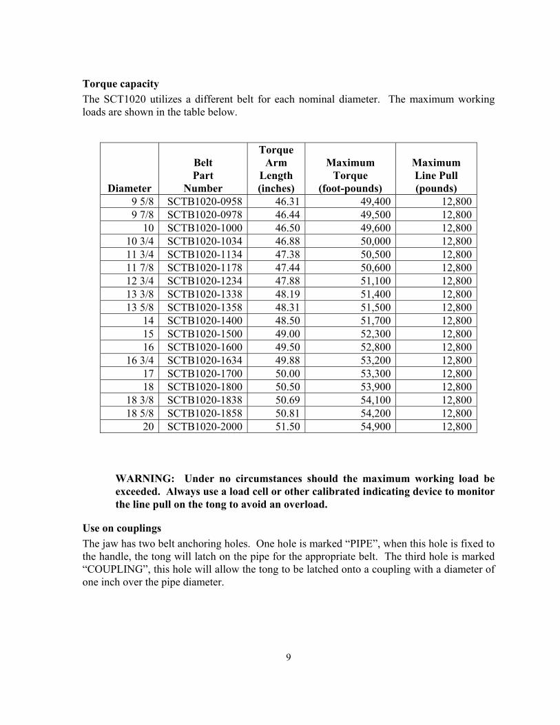
15
Weld blending and inspection The weld is to be ground flush with the adjacent parent material The weld is to be inspected by magnetic particle to verify that the weld area is free of all crack indications
16
Certificates

16
Certificates