periodic topology optimization of a stacker crane
TRANSCRIPT

University of Wollongong University of Wollongong
Research Online Research Online
Faculty of Engineering and Information Sciences - Papers: Part B
Faculty of Engineering and Information Sciences
2019
Periodic topology optimization of a stacker crane Periodic topology optimization of a stacker crane
Hongyu Jiao [email protected]
Feng Li
Zhengyi Jiang University of Wollongong, [email protected]
Ying Li
Zhao Yu
Follow this and additional works at: https://ro.uow.edu.au/eispapers1
Part of the Engineering Commons, and the Science and Technology Studies Commons
Recommended Citation Recommended Citation Jiao, Hongyu; Li, Feng; Jiang, Zhengyi; Li, Ying; and Yu, Zhao, "Periodic topology optimization of a stacker crane" (2019). Faculty of Engineering and Information Sciences - Papers: Part B. 3677. https://ro.uow.edu.au/eispapers1/3677
Research Online is the open access institutional repository for the University of Wollongong. For further information contact the UOW Library: [email protected]
Periodic topology optimization of a stacker crane Periodic topology optimization of a stacker crane
Abstract Abstract © 2013 IEEE. The stacker crane is a long-and-thin structure with a large length-to-width ratio. It is difficult to obtain a topology configuration with good period properties using traditional optimization methods. While the mathematical model of periodic topology optimization - in which the elements' relative densities are selected as design variables, and mean compliance as the objective function - is established. To find a topology configuration with a good period property, an additional constraint condition must be imported into the mathematical model. According to the optimization criteria method, the iterative formula of design variables is derived in the virtual sub domain. To verify the capability and availability of the proposed method, periodic topology optimization of a single-mast stacker crane is investigated in this paper. The results show that configurations with good periodicity can be obtained when the number of sub domains is varied. After considering mean compliance and complexity, the optimal configuration has eight periods. A preliminary lightweight design scheme is proposed based on this configuration of a stacker crane, which is a periodic feature structure.
Disciplines Disciplines Engineering | Science and Technology Studies
Publication Details Publication Details Jiao, H., Li, F., Jiang, Z., Li, Y. & Yu, Z. (2019). Periodic topology optimization of a stacker crane. IEEE Access, 7 186553-186562.
This journal article is available at Research Online: https://ro.uow.edu.au/eispapers1/3677
Received November 19, 2019, accepted December 12, 2019, date of publication December 17, 2019,date of current version December 31, 2019.
Digital Object Identifier 10.1109/ACCESS.2019.2960327
Periodic Topology Optimizationof a Stacker CraneHONG-YU JIAO 1,2,3, FENG LI 1, ZHENG-YI JIANG 3, YING LI 2, AND ZHAO-PENG YU 21Suzhou Institute of Nano-Tech and Nano-Bionics (SINANO), Chinese Academy of Sciences, Suzhou 215000, China2School of Automotive Engineering, Changshu Institute of Technology, Suzhou 215500, China3School of Mechanical, Materials, Mechatronic and Biomedical Engineering, University of Wollongong, Wollongong, NSW 2519, Australia
Corresponding author: Zhao-Peng Yu ([email protected])
This work was supported in part by the National Natural Science Foundation of China under Grant 51605046, and in part by the JiangsuProvincial Government Scholarship Program under Grant JS-2017-188.
ABSTRACT The stacker crane is a long-and-thin structure with a large length-to-width ratio. It is difficult toobtain a topology configuration with good period properties using traditional optimization methods. Whilethe mathematical model of periodic topology optimization—in which the elements’ relative densities areselected as design variables, and mean compliance as the objective function—is established. To find atopology configuration with a good period property, an additional constraint condition must be importedinto the mathematical model. According to the optimization criteria method, the iterative formula of designvariables is derived in the virtual sub domain. To verify the capability and availability of the proposedmethod,periodic topology optimization of a single-mast stacker crane is investigated in this paper. The results showthat configurations with good periodicity can be obtained when the number of sub domains is varied. Afterconsidering mean compliance and complexity, the optimal configuration has eight periods. A preliminarylightweight design scheme is proposed based on this configuration of a stacker crane, which is a periodicfeature structure.
INDEX TERMS Periodic topology optimization, long-and-thin structures, stacker crane, variable densitymethod, optimization criteria method.
I. INTRODUCTIONAn effective design tool, structural topology optimization,can obtain a lighter structure than size and shape optimiza-tion, and it has broad application prospects with regard to thelightweight design of engineering structures [1]–[4]. Therehave been many topology optimization methods presented,including the homogenization method [5], [6], variable den-sity method [7], [8], level set method [9], [10], evolution-ary structural optimization method [11], [12], phase fieldmethod [13], [14], independent continuous mapping method[15], [16] and topological derivative method [17]. Manyinternational research studies have been carried out on thistopic. Yuanfang et al. [18] used topology optimization tostudy a mini-electrical vehicle frame. Considering the impactloads under multiple working conditions, a new structure wasproposed using the variable density method to meet layoutand real driving demands. The new structure is rational andcan reduce the weight of the mini-electrical vehicle frameand improve mechanical performance. The modified P-norm
The associate editor coordinating the review of this manuscript and
approving it for publication was Wei Wei .
correction method proposed by Lee et al. was used to presentmaximum stress-constrained structural optimization basedon the phase field design method [19]. To overcome thelimitation of conventional P-norm methods, the lower-boundP-norm stress curve was employed. Lightweight designs forthe L-shaped and cantilever beams were proposed for the ver-ification of the proposed method under the condition of yieldstrength constraint. The level set-based topology optimizationmethod proposed by Wang and Kang [9] was used to studythe design of structures with coating layers. The optimizationproblem of compliance minimization was considered with amaterial mass constraint. To solve the optimization problem,the steepest descent methodwas used. Some examples in both2D and 3D designable domains were researched to show theeffectiveness of the proposed method. The variable densitymethod, phase field design method, and level set method canbe used to research the topology optimization of engineeringstructures. However, topology configurations with periodic-ity are not obtained through these traditional methods.
Periodic feature structures have attracted the attention ofacademic and industrial technicians with their unique struc-tural form, excellent visual aesthetics, extensibility in array
VOLUME 7, 2019 This work is licensed under a Creative Commons Attribution 4.0 License. For more information, see http://creativecommons.org/licenses/by/4.0/ 186553

H.-Y. Jiao et al.: Periodic Topology Optimization of a Stacker Crane
direction, physical versatility, and good manufacturing anddesign [20]–[25]. Many topology optimization methods havebeen presented to research periodic topology optimization,including the homogenization method, evolutionary struc-tural optimization method [26]–[29], and independent con-tinuous mapping method [30], [31]. Huang and Xie [26]used bidirectional evolutionary structural optimization toresearch the topology optimization of periodic structures andpresented a new method. This method is widely appliedto structural periodic topology optimization problems oncyclic-symmetry structures [27], natural frequencies [28] andunstructured design points [29]. The topology optimizationmodel of the periodic structures was established by Longand Jia using the solid isotropic material with penaliza-tion (SIMP) method and the independent continuous map-ping (ICM) method. This model is used to optimize theoptimal topological configuration for thermal conductivemicrostructures of compositematerials [30], [31]. The stackercrane is considered a long-and-thin structure because it hasa large length-to-width ratio. It is often difficult to obtaina topology configuration with a good period property bytraditional topology optimization methods. The abovemen-tioned studies provide an important basis and reference forthe topology optimization of stacker cranes.
The paper is structured as follows. First, in the secondsection, we introduce the problem description of periodictopology optimization and the material interpolation model.In the third section, the mathematical model of periodictopology optimization is established. The iterative formulaof the virtual sub domain can be obtained based on theoptimization criteria method. Section 4 presents the filterfunction and convergence criterion. Section 5 studies finiteelement analysis of a single-mast stacker crane. To verify thecapability and availability of the proposed method, periodictopology optimization of stacker cranes is investigated insection 6. A preliminary lightweight design scheme is pro-posed in section 7. Final conclusions are drawn in section 8.
II. LONG-AND-THIN STRUCTURES FORPERIODIC DESIGNA. PROBLEM DESCRIPTION OF PERIODIC TOPOLOGYOPTIMIZATIONThe objective of periodic topology optimization is to seekan optimal topology configuration with good period prop-erties. To consider the periodicity of long-and-thin struc-tures in a given design domain, the design domain isdivided into m sub domains on the length direction, wherem denotes the number of sub domains along direction x,as shown in Fig. 1. The number of sub domains is usu-ally prescribed according to the length-to-width ratio oflong-and-thin structures. The conventional topology opti-mization is considered periodic topology optimization form = 1. xi,j is the design variable, where i denotes thesub domain number, and j denotes the element number in asub domain.
FIGURE 1. Design domain with m=3 sub domains.
B. MATERIAL INTERPOLATION MODEL INTHE VARIABLE DENSITY METHODSIMP is one of the most popular material interpolation meth-ods and was first considered by Bendsøe in 1989. This inter-polation model is referred to as the power law or penalized,proportional stiffness model [32]. In this paper, the relation-ship between the modulus of elasticity after interpolation andrelative density is expressed as:
E(xi,j) = Emin + (xi,j)p(E0 − Emin) (1)
where E(xi,j) is the modulus of elasticity after interpolation,E0 is the modulus of elasticity of the material, Emin is usuallyrestricted to 0.001∗E0 for the numerical stability, xi,j is therelative density of the jth element in the ith sub domain, andp is the penalization factor.
III. SOLVING THE PROBLEM OF PERIODICTOPOLOGY OPTIMIZATIONA. MATHEMATICAL MODEL OF PERIODICTOPOLOGY OPTIMIZATIONThe objective function of periodic topology optimization isto minimize the mean compliance of long-and-thin struc-tures subjected to volume constraints and other factors. Theelements’ relative densities are selected as design variables.Based on the variable density method, the mathematicalmodel of periodic topology optimization can be written as:
Find X = (x1,1, x1,2, x1,3, . . . , xi,j)T ∈ R
i = 1, 2, · · · ,m, j = 1, 2, · · · , n
Min C(X) =12FTU =
12UTKU
=12
m∑i=1
n∑j=1
uTi,jki,jui,j =12
m∑i=1
n∑j=1
(xi,j)p uTi,jk0ui,j
s.t KU = F
V = f · V0 =m∑i=1
n∑j=1
xi,j · vi,j
x1,j = · · · = xi,j = · · · xm,j0 < xmin ≤ xi,j ≤ xmax ≤ 1 (2)
where C is the mean compliance; U and F are the displace-ment vectors and applied load, respectively; K is the totalstiffness matrix; vi,j and ki,j are the volume and the stiffnessmatrix, respectively, of the jth element in the ith sub domain;ui,j is the nodal displacement vector of the jth element in
186554 VOLUME 7, 2019

H.-Y. Jiao et al.: Periodic Topology Optimization of a Stacker Crane
the ith sub domain; and xmax and xmin are the maximum andminimum relative density of elements, respectively.
To make each sub domain have a periodic topology config-uration, a constraint condition is set up in the mathematicalmodel, which is expressed as:
x1,j = · · · = xi,j = · · · xm,j (3)
The solution method of topology optimization is generallydivided into two categories: the mathematical programmingmethod [33], [34] and the optimization criteria method [35],[36]. The mathematical programming method is highly ver-satile and can be applied to different optimization problems.However, the number of iterations is large, and the solutionefficiency is not high. The outstanding advantage of the opti-mization criteria method is that the convergence speed is fast,the number of iterations is small, and it has nothing to do withthe size and complexity of the structure. The topology opti-mization problem with simple constraints and a large numberof optimization variables has higher efficiency. Due to theabove advantages, the optimization criteriamethod is selectedas the solution method of periodic topology optimization.
B. OPTIMIZATION CRITERIA METHOD FOR PERIODICTOPOLOGY OPTIMIZATIONThe optimization criteria formula, which consists of an objec-tive function and constraint conditions, can be derived fromthe Lagrange function [37]. The Lagrange function of theperiodic topology optimization problem can be written as:
L = C + λ1 (V − f · V0)+ λT2 (KU − F)
+
m∑i=1
n∑j=1
λ3i,j(xmin − xi,j + a2i,j)
+
m∑i=1
n∑j=1
λ4i,j(xi,j − xmax + b2i,j)+m−1∑i=1
βi(xi,j − xi+1,j
)(4)
where λ1,λ2, λ3i,j, λ4i,j, βi are Lagrange multipliers; λ1,λ3i,j, λ4i,j, βi are scalars; λ2 is a column vector; and a2i,j andb2i,j are relaxation factors.When xi,j is taken as the extreme value x∗i,j, the Lagrange
function should satisfy the following Kuhn-Tuckerconditions:
∂L∂xi,j=∂C∂xi,j+ λ1
∂V∂xi,j+ λT
2∂ (KU)xi,j
− λ3i,j + λ4i,j = 0
V = f · V0F = KUλ3i,j
(xmin − xi,j
)= 0 i = 1, 2, · · · ,m
λ4i,j(xi,j − xmax
)= 0 j = 1, 2, · · · , n
λ3i,j > 0λ4i,j > 0xmin ≤ xi,j ≤ xmax
(5)
If xmin < xi,j < xmax, then:
∂L∂xi,j=∂C∂xi,j+ λ1
∂V∂xi,j+ λT
2∂ (KU)∂xi,j
= 0 (6)
When the equation C = 1/2U
TKU is plugged into Eq.6,the following can be obtained:
∂L∂xi,j=
12(∂UT
∂xi,jKU + UT ∂K
∂xi,jU + UTK
∂U∂xi,j
)
+ λ1∂V∂xi,j+ λT
2
(∂K∂xi,j
U + K∂U∂xi,j
)= 0 (7)
Using the symmetry of the stiffness matrix, Eq. 7 can bewritten as:∂L∂xi,j= (λT
2K + UTK)
∂U∂xi,j+ λ1
∂V∂xi,j
+
(12UT+ λT
2
)∂K∂xi,j
U = 0 (8)
If λ2 is a column vector and its value is no limit. Theequation λ2 = −U is substituted with Eq.8, and then thefollowing can be obtained:
∂L∂xi,j= −
12UT ∂K
∂xi,jU + λ1
∂V∂xi,j= 0 (9)
When the equations ki,j = (xi,j)pk0 and V =m∑i=1
n∑j=1
xi,jvi,j
are plugged into Eq.9, then:
−p2(xi,j)p1uTi,jk0ui,j + λ1vi,j = 0 (10)
Usually, the design domain is divided into several elementsin which the element size is identical. Thus, element volumevi,j in the design domain is given by:
vi,j = v0 (11)
where v0 is the volume of finite element mesh.Then, multiply both sides by xi,j
/p:
12uTi,jki,jui,j =
λ1v0p× xi,j (12)
The strain energy of the jth element in the ith sub domainis calculated by:
ci,j =12uTi,jki,jui,j (13)
Then, Eq. 12 is expressed as:
ci,j =λ1v0p× xi,j (14)
Eq.14 applies to all elements in the design domain. Itsphysical meaning is that the relative density is proportionalto the strain energy of the element. It is easy to find that bothsides of Eq.14 are summed simultaneously, and then
m∑i=1
ci,j =λ1v0p×
m∑i=1
xi,j (15)
VOLUME 7, 2019 186555

H.-Y. Jiao et al.: Periodic Topology Optimization of a Stacker Crane
A virtual sub domain is constructed, and the size, number,and distribution of elements in the virtual sub domain mustbe identical to each sub domain. The average strain energy ofelements in all sub domains is taken as the strain energy ofelements in the virtual sub domain, which can be formulatedas follows:
cj =1m
m∑i=1
ci,j (16)
To obtain an optimal periodic topology, a constraint condi-tion is set up. This means that the average relative density ofthe jth element in all sub domains is calculated as:
xj =1m
m∑i=1
xi,j = xi,j (17)
If we put Eq. 16 and Eq. 17 into Eq. 15, we obtain thefollowing:
cj =λ1v0p× xj (18)
The physical meaning of Eq. 18 is that the relative densityis proportional to the strain energy of elements in the virtualsub domain. It is expressed in another form as:
D(k)j =
pcjλ1v0xj
= 1 (19)
The iterative formula of the virtual sub domain based onthe optimality criterion method can be obtained, as follows:
x(k+1)j =
[D(k)j
]ηx(k)j xmin <
[D(k)j
]ηx(k)j < xmax
xmin
[D(k)j
]ηx(k)j ≤ xmin
xmax
[D(k)j
]ηx(k)j ≥ xmax
(20)
where η is the damping coefficient. It is generally taken as0.5. The aim of introducing η is to ensure that optimizationresults are convergent.
IV. FILTER FUNCTION AND CONVERGENCE CRITERIONA. FILTER FUNCTIONDue to the instability of numerical calculations, checker-board patterns are often observed in the topology optimiza-tion process. A filter function proposed by Sigmund andPetersson in 1998 is imported to solve these checkerboardand mesh-independent problems [38]. Huang and Xie [39]studied convergent and mesh-independent solutions for theBESO method. A mesh-independency filter function wasintroduced into BESO to determine the addition of elementsand to eliminate unnecessary structural details below a certainlength scale in the design. Based on the filtration scheme inreference [39], an improved filtration scheme was proposedbased on the element strain energy.
The zone �a denotes an open ball centered on element aand with a radius of rmin. We note that all elements in the
zone are used to calculate the strain energy of element a afterfiltering:
c′a =
l∑e=1
dece
l∑e=1
de
(21)
where c′a is the strain energy of element a after filtering; ceis the strain energy of element e before filtering, which is ci,jin Eqs. 13∼16 replacing the subscript symbol because i isthe sub domain number, and its value is i = 1, 2, . . . ,m;j is the element number in a sub domain, and its value isj = 1, 2, . . . , n. There are N = m × n elements in the entireoptimization domain. The strain energy of all the elementsin the entire optimization domain can be filtered as a whole,and it is not necessary to distinguish each sub domain. Thus,the subscript of the element strain energy symbol is replacedin Eq. 21. l is the element number in zone�a. de is the weightcoefficient:
de = rmin − rea (22)
where rea is the distance from the center of each element inthe zone to the center of element a.
B. CONVERGENCE CRITERIONIt is well known that if the relative error τ of the two adja-cent optimization results is less than the given convergenceaccuracy τmax = 0.001, then the periodic layout optimiza-tion has converged. The mean compliance is selected as theobjective function of periodic topology optimization. Therelative change in the objective function is regarded as theconvergence criterion. It can be formulated as follows:
τ =
∣∣∣∣ N∑k=1
(Ck− Ck−1)
∣∣∣∣N∑k=1
Ck−1
≤ τmax (23)
In the optimization process, the relative error τ of the twoadjacent optimization results must be calculated. When theconvergence criterion shown in Eq.23 is satisfied, we proposethat xi,j is taken as the extreme value x∗i,j.
V. FINITE ELEMENT ANALYSIS OF A SINGLE-MASTSTACKER CRANEA. THE MECHANICAL MODEL OF A SINGLE-MASTSTACKER CRANESingle-mast stacker cranes are in their worst condition whenthe pallet is fully loaded and extended to the highest position.If a single-mast stacker crane is simplified as the mast andbottom end rail. Other parts are equivalent to forces in themechanical model [40]–[42] shown in Fig. 2, as follows: Hand B are the height and wheel track of the stacker crane, andPH is a horizontal inertia force. When the stacker crane is ina condition of rest, the value of PH is zero; h is the distance
186556 VOLUME 7, 2019

H.-Y. Jiao et al.: Periodic Topology Optimization of a Stacker Crane
FIGURE 2. Mechanical model of a single-mast stacker crane.
of top contact roller and the top of mast; b1 and b2 are thedistance of the neutral axis of the mast cross section and twofulcrums of the bottom end rail, respectively; F is an axialforce on the top of the mast; and Pz is a horizontal forcebetween the mast and rollers.
B. FINITE ELEMENT MODEL OF A STACKER CRANEOur research object is a single-mast stacker crane with a1-ton lifting capacity Q and 8 meters of lifting height H.The mast and bottom end rail are welded with several piecesof steel plate of different thicknesses. The mast and bot-tom end rail are simulated with shell element 63 for dif-ferent thicknesses, and the material is steel Q235B. Theguide rail adopts 60×40 square steel from steel Q345. Theguide rail is simulated with beam element 188. The finiteelement model of a stacker crane is established in ANSYSshown in Fig. 3.
The constraints and loads are applied to the finite elementmodel according to the mechanical model shown in Fig. 2.The bottom end rail is studied as simply a supported beam.The most dangerous condition is when the pallet is fullyloaded at the highest position. In this case, the force con-dition of the mast is the most unfavorable. The horizontalforce between the mast and rollers Pz and axial force onthe top of mast F can be obtained from the equilibriumcondition of mechanics. Please see the reference [41] forthe details.
The finite element analysis of a single-mast stacker craneis implemented programmatically using the ANSYS APDLlanguage. Its purpose is to facilitate multiple finite elementanalysis in the topology optimization process.
C. STRENGTH ANALYSISThe stacker crane is regarded as a bidirectional bendingmember. Its verifying calculation of strength is performedusing the National Standard of China GB50017-2017 Codefor Design of Steel Structures [43]. Basic allowable stress
FIGURE 3. Finite element model of a stacker crane.
FIGURE 4. Equivalent stress cloud diagram of a stacker crane.
should be met as follows:
[σ ] = 180MPa (24)
The equivalent stress cloud diagram of a stacker crane isshown in Fig. 4. The maximum equivalent stress is 54.9 MPa,which appears at the junction of the bottom end rail andthe mast. The maximum equivalent stress is less than thebasic allowable stress, which meets the requirements for thestrength of a stacker crane in the Code for Design of SteelStructures. The equivalent stress of the roller action area onthe stacker crane is large, while other areas are in the low-stress area. This shows that the stacker crane has a largepotential for weight reduction.
D. STATIC STIFFNESS ANALYSISThere is no requirement for static stiffness of the bendingmember in the Code for Design of Steel Structures. There isno uniform standard for the static stiffness of a stacker crane.According to design experience, the allowable value of the
VOLUME 7, 2019 186557

H.-Y. Jiao et al.: Periodic Topology Optimization of a Stacker Crane
FIGURE 5. Displacement cloud diagram of a stacker crane alongdirection x.
FIGURE 6. Optimization domain of a stacker crane.
FIGURE 7. Optimization curve of mean compliance, volume ratio,maximum equivalent stress and maximum displacement along direction xfor m=8.
static deflection [f ] usually satisfies the requirement as:
[f ] =H
2000∼
H1000
= 4 ∼ 8mm (25)
The displacement cloud diagram of a stacker crane alongdirection x is shown in Fig. 5. The maximum displacementalong direction x is 1.085 mm, which appears at the topof the mast. The maximum displacement is much smallerthan the allowable static deflection, which meets the design’sempirical requirements.
FIGURE 8. Process of periodic topology optimization for m=8.
VI. PERIODIC TOPOLOGY OPTIMIZATIONOF A SINGLE-MAST STACKER CRANEA. OPTIMIZATION DOMAIN AND PARAMETERSOF PERIODIC TOPOLOGY OPTIMIZATIONFOR A STACKER CRANEThe optimization domain, with H1 = 7.2 m and W = 0.6m, is in the middle of the mast frontage, as shown in Fig. 6.The optimization domain is divided into m = 6, 8, 9 and12 sub domains by partitions for Hz = 1.2 m, 0.9 m, 0.8 mand 0.6 m, respectively. The bottom end rail and other areasof the mast are non-optimization domains. Periodic topologyoptimization of the stacker crane is conducted based on thevariable density method, in which elements’ relative densitiesare selected as design variables and mean compliance isselected as the objective function under volume constraints.The modulus of elasticity of material and Poisson’s ratio ofmaterial are E0 = 210 GPa and v = 0.3. The penalizationfactor and volume ratio are p = 3 and f = 35%, respectively.
186558 VOLUME 7, 2019

H.-Y. Jiao et al.: Periodic Topology Optimization of a Stacker Crane
FIGURE 9. Optimal topology of a stacker crane for m=8.
The filtering radius and initial value of the design variable arermin = 0.04 m and X (0)
= (1, 1, · · · , 1)Tm×n.
B. PERIODIC TOPOLOGY OPTIMIZATION OFA STACKER CRANE FOR m=8Fig. 7 shows the optimization curve of mean compliance C ,volume ratio f , maximum equivalent stress and maximumdisplacement along direction x for m = 8. The mean com-pliance increases slowly as the volume ratio decreases stably.After 60 iterations, the volume ratio reaches 35%. Addition-ally, mean compliance varies from 1.777 N.m to 5.465 N.m.The maximum equivalent stress increases from 54.9 MPa to69.3 MPa, and the maximum displacement along direction xranges from 1.085 mm to 1.431 mm. The strength and staticstiffness of the stacker crane still meet the requirements forthe strength of a stacker crane in the Code for Design of SteelStructures and empirical design.
To distinctly express the process of periodic topology opti-mization, certain parts of the stacker crane are amplified.Fig. 8 shows the process of periodic topology optimizationfor m = 8, and Fig. 8f is the optimal periodic topologyconfiguration. All elements with relative densities greaterthan 0.1 are displayed. Two holes appear simultaneously ineach sub domain, which is a good period property. With thenumber of iterations increasing, some holes increase gradu-ally or merge together. After the 35th iteration, the numberof holes in each sub domain does not change, which meansthat the main body of optimal topology is forming. Untilperiodic topology optimization is complete, a similar trussedtopology configuration is obtained, which has good period-icity. Fig. 8 shows the optimal topology of a stacker cranefor m = 8, which is displayed entirely. Fig. 9a is the stereoview of the optimal topology, and Fig. 9b is the front view.
FIGURE 10. Optimal topology of a stacker crane for m=6.
FIGURE 11. Optimal topology of a stacker crane for m=9.
The optimal topology is composed of eight upside-down ‘M’shapes, which satisfy the defined periodic conditions.
C. PERIODIC TOPOLOGY OPTIMIZATION OF A STACKERCRANE FOR m=6, 9, 12Fig. 10, Fig. 11 and Fig. 12 show the optimal topologies of astacker crane for m = 6, 9, and 12, respectively. The optimaltopology form = 6 is presented as six ‘M’ shapes, which have
VOLUME 7, 2019 186559

H.-Y. Jiao et al.: Periodic Topology Optimization of a Stacker Crane
FIGURE 12. Optimal topology of a stacker crane for m=12.
FIGURE 13. Curve of mean compliance, iteration number, maximumequivalent stress, and maximum displacement along direction x with subdomain number in the optimal topology.
a good period property. The optimal topology for m = 9 ismore complicated than the optimal topology for m = 6 and8. The optimal topology for m = 12 is composed of 12 ‘X’shapes. As the number of sub domains increases, differentoptimal topology configurations can be similarly obtained.This is mainly due to the change in the length-width ratio inthe sub domain.
D. FINAL OPTIMAL TOPOLOGY OF A STACKER CRANEFig. 13 shows the curve of mean compliance C , itera-tions k , maximum equivalent stress and maximum displace-ment along direction x with the sub domain number in theoptimal topology. When the sub domain numbers are6 and 12, the maximum displacements along direction x are15.12 mm and 13.52 mm, respectively, which do not satisfythe requirement for the static stiffness of a stacker crane.
FIGURE 14. Equivalent stress cloud diagram of a stacker crane afteroptimization for m=8.
FIGURE 15. Displacement cloud diagram of a stacker crane alongdirection x after optimization for m=8.
The equivalent stress cloud diagram of a stacker crane afteroptimization for m = 8 is shown in Fig. 14. The maximumequivalent stress after optimization is 69.3 MPa. It is stillsmaller than the basic allowable stress, which meets therequirements for the strength of a stacker crane in theCode forDesign of Steel Structures. The displacement cloud diagramof a stacker crane along direction x after optimization form = 8 is shown in Fig. 15. The maximum displacement alongdirection x is 1.431 mm. It is still smaller than the allowablestatic deflection, which meets the design’s empirical require-ments. By considering mean compliance and the complexityof optimal topology configuration further, the optimal topol-ogy for m = 8 is the final optimal topology of periodictopology optimization for a stacker crane.
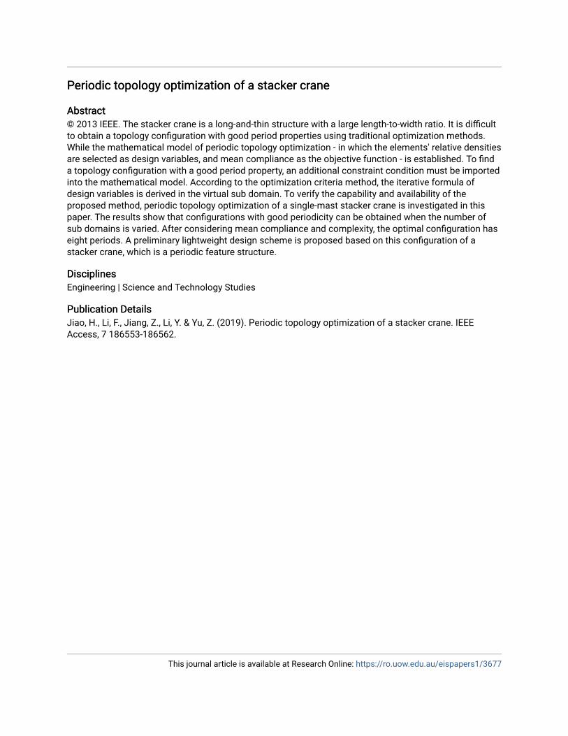
VII. LIGHTWEIGHT DESIGNS FOR THESTACKER CRANEA preliminary lightweight design scheme is proposed basedon the final optimal topology of the stacker crane, whichis a periodic feature structure, as shown in Fig. 16.
186560 VOLUME 7, 2019
H.-Y. Jiao et al.: Periodic Topology Optimization of a Stacker Crane
FIGURE 16. A preliminary lightweight design scheme for the stacker.
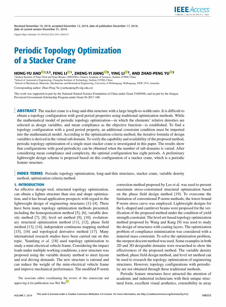
FIGURE 17. Process plan of sub domains.
The optimization domain is divided into eight by partitions.Each part has triangular form holes, and three corners of thehole are rounded off, as shown in Fig. 17.
VIII. CONCLUSIONIn this paper, a method for periodic topology optimization oflong-and-thin structures has been presented using the vari-able density method. The mathematical model of periodictopology optimization, in which elements’ relative densitiesare selected as design variables and mean compliance asthe objective function, has been established. An additionalperiodic constraint has been added to the mathematical modelto ensure that the structure comprises a prescribed numberof identical sub domains. The iterative formula of the virtualsub domain can be obtained based on the optimization criteriamethod.
To verify the capability and availability of the proposedmethod, periodic topology optimization of a single-maststacker crane was investigated. The results show that a similartrussed topology configuration is obtained, which has goodperiodicity. As the number of sub domains increases, dif-ferent optimal topology configurations with periodicity canbe obtained likewise. This is mainly due to the change inthe length-width ratio in the sub domain. By considering themean compliance and complexity of the optimal topologyconfiguration, the optimal topology for m = 8 is the finaloptimal topology of periodic topology optimization for thestacker crane.
A preliminary lightweight design scheme is proposedbased on the final optimal topology of a stacker crane, whichis a periodic feature structure.
REFERENCES[1] N. Ryu, W. S. Song, Y. Jung, and S. Min, ‘‘Multi-objective topology
optimization of a magnetic actuator using an adaptive weight and tunnelingmethod,’’ IEEE Trans. Magn., vol. 55, no. 6, Jun. 2019, Art. no. 7202504.
[2] F. C. Potes, J. M. Silva, and P. V. Gamboa, ‘‘Development and character-ization of a natural lightweight composite solution for aircraft structuralapplications,’’ Compos. Struct., vol. 136, no. 2, pp. 430–440, 2016.
[3] S. Doi, H. Sasaki, and H. Igarashi, ‘‘Multi-objective topology optimizationof rotating machines using deep learning,’’ IEEE Trans. Magn., vol. 55,no. 6, Jun. 2019, Art. no. 7202605.
[4] M. Xia, S. Yang, and S. Ho, ‘‘A new topology optimization methodologybased on constraint maximum-weight connected graph theorem,’’ IEEETrans. Magn., vol. 54, no. 3, Mar. 2018, Art. no. 7001204.
[5] Y. Noguchi, T. Yamada, and S. Nishiwaki, ‘‘Topology optimization forhyperbolic acoustic metamaterials using a high-frequency homogenizationmethod,’’ Comput. Methods Appl. Mech. Eng., vol. 335, pp. 419–471,Jun. 2018.
[6] G. Allaire, P. Geoffroy-Donders, and O. Pantz, ‘‘Topology optimization ofmodulated and oriented periodic microstructures by the homogenizationmethod,’’ Comput. Math. Appl., vol. 78, no. 7, pp. 2197–2229, 2018.
[7] F. Zhao, ‘‘Topology optimization with meshless density variable approx-imations and BESO method,’’ Comput.-Aided Des., vol. 56, pp. 1–10,Nov. 2014.
[8] V. Kandemir, O. Dogan, and U. Yaman, ‘‘Topology optimization of 2.5 Dparts using the SIMP method with a variable thickness approach,’’ Proce-dia Manuf., vol. 17, pp. 29–36, Jun. 2018.
[9] Y. Wang and Z. Kang, ‘‘A level set method for shape and topologyoptimization of coated structures,’’ Comput. Methods Appl. Mech. Eng.,vol. 329, pp. 553–574, Feb. 2018.
[10] W.Khan and B. Ullah, ‘‘Structural optimization based onmeshless elementfree Galerkin and level set methods,’’ Comput. Methods Appl. Mech. Eng.,vol. 344, pp. 144–163, Feb. 2019.
[11] L. Xia, L. Zhang, Q. Xia, and T. Shi, ‘‘Stress-based topology optimizationusing bi-directional evolutionary structural optimization method,’’ Com-put. Methods Appl. Mech. Eng., vol. 333, pp. 356–370, May 2018.
[12] L. Xia, Q. Xia, X. Huang, and Y. M. Xie, ‘‘Bi-directional evolutionarystructural optimization on advanced structures and materials: A compre-hensive review,’’ Arch. Comput. Methods Eng., vol. 25, no. 2, pp. 437–478,2018.
[13] M. Y. Wang and S. Zhou, ‘‘Phase field: A variational method for struc-tural topology optimization,’’ Comput. Model Eng. Sci., vol. 6, no. 6,pp. 547–566, Dec. 2004.
[14] A. Takezawa, S. Nishiwaki, and M. Kitamura, ‘‘Shape and topologyoptimization based on the phase field method and sensitivity analysis,’’J. Comput. Phys., vol. 229, no. 7, pp. 2697–2718, Apr. 2010.
[15] Y. Sui, J. Du, and Y. Guo, ‘‘Independent continuous mapping for topolog-ical optimization of frame structures,’’ Acta Mech. Sinica, vol. 22, p. 611,Dec. 2006.
[16] J. Du, Y. Guo, Z. Chen, and Y. Sui, ‘‘Topology optimization of continuumstructures considering damage based on independent continuous mappingmethod,’’ Acta Mech. Sinica, vol. 35, no. 2, pp. 433–444, Apr. 2019.
[17] J. Sokołowski and A. Żochowski, ‘‘On the topological derivative in shapeoptimization,’’ SIAM J. Control Optim., vol. 37, no. 4, pp. 1251–1272,1999.
[18] F. Yuanfang, J. Dafeng, and Q. Weiwei, ‘‘Optimazation method for a minielectric vehicle frame structure,’’ J.Mech. Eng., vol. 45, no. 9, pp. 210–213,2009.
[19] K. Lee, K. Ahn, and J. Yoo, ‘‘A novel P-norm correction method forlightweight topology optimization under maximum stress constraints,’’Comput. Struct., vol. 171, pp. 18–30, Jul. 2016.
[20] Y. Chen, S. Zhou, and Q. Li, ‘‘Multiobjective topology optimizationfor finite periodic structures,’’ Comput. Struct., vol. 88, nos. 11–12,pp. 806–811, 2010.
[21] Z. H. Zuo, X. Huang, X. Yang, J. H. Rong, and Y. M. Xie, ‘‘Comparingoptimal material microstructures with optimal periodic structures,’’ Com-put. Mater. Sci., vol. 69, pp. 137–147, Mar. 2013.
[22] Y. Chen, P. Sareh, J. Feng, and Q. Sun, ‘‘A computational method forautomated detection of engineering structures with cyclic symmetries,’’Comput. Struct., vol. 191, pp. 153–164, Oct. 2017.
[23] Y. Tang, G. Dong, Q. Zhou, and Y. F. Zhao, ‘‘Lattice structuredesign and optimization with additive manufacturing constraints,’’IEEE Trans. Autom. Sci. Eng., vol. 15, no. 4, pp. 1546–1562,Oct. 2018.
[24] B. Yi, Y. Zhou, G. H. Yoon, and K. Saitou, ‘‘Topology opti-mization of functionally-graded lattice structures with buckling con-straints,’’ Comput. Methods Appl. Mech. Eng., vol. 354, pp. 593–619,Sep. 2019.
VOLUME 7, 2019 186561

H.-Y. Jiao et al.: Periodic Topology Optimization of a Stacker Crane
[25] M. Cui, X. Yang, Y. Zhang, C. Luo, and G. Li, ‘‘An asymptoticallyconcentrated method for structural topology optimization based on theSIMLF interpolation,’’ Int. J. Numer. Methods Eng., vol. 115, no. 10,pp. 1175–1216, Sep. 2018.
[26] X. Huang and Y. M. Xie, ‘‘Optimal design of periodic structures usingevolutionary topology optimization,’’ Struct. Multidisciplinary Optim.,vol. 36, no. 6, pp. 597–606, 2008.
[27] T. Gao, W. H. Zhang, J. H. Zhu, and X. G. Tang, ‘‘Evolutionary statictopology optimization of cyclic-symmetry structures,’’ Chin. J. Mech.Eng., vol. 44, no. 3, pp. 166–172, 2008.
[28] Z. H. Zuo, Y. M. Xie, and X. Huang, ‘‘Optimal topological design ofperiodic structures for natural frequencies,’’ J. Struct. Eng., vol. 137, no. 10,pp. 1229–1240, 2011.
[29] G. He, X. Huang, H. Wang, and G. Li, ‘‘Topology optimization of peri-odic structures using BESO based on unstructured design points,’’ Struct.Multidisciplinary Optim., vol. 53, no. 2, pp. 271–275, 2016.
[30] K. Long and J. Jia, ‘‘Periodic topology optimization design for thermalconductive structures using ICM method,’’ Eng. Mech., vol. 32, no. 5,pp. 227–235, 2015.
[31] J. Jia and K. Long, ‘‘Topology optimization for periodic thermal conduc-tive material suing SIMP method,’’ J. Beijing Univ. Aeronaut. Astronaut.,vol. 41, no. 6, pp. 1042–1048, 2015.
[32] A. Rietz, ‘‘Sufficiency of a finite exponent in SIMP (power law) methods,’’Struct. Multidisciplinary Optim., vol. 21, no. 2, pp. 159–163, Apr. 2001.
[33] Y. Liang and G. Cheng, ‘‘Topology optimization via sequential integer pro-gramming and canonical relaxation algorithm,’’ Comput. Methods Appl.Mech. Eng., vol. 348, pp. 64–96, May 2019.
[34] R. Sivapuram and R. Picelli, ‘‘Topology optimization of binary structuresusing integer linear programming,’’ Finite Elements Anal. Des., vol. 139,pp. 49–61, Feb. 2018.
[35] K. C. Nguyen, P. Tran, and H. X. Nguyen, ‘‘Multi-material topology opti-mization for additive manufacturing using polytree-based adaptive polyg-onal finite elements,’’ Autom. Construct., vol. 99, pp. 79–90, Mar. 2019.
[36] Z. Chen, L. Gao, H. Qiu, and X. Shao, ‘‘Combining genetic algorithmswith optimality criteria method for topology optimization,’’ in Proc. IEEE4th Int. Conf. Bio-Inspired Comput., Oct. 2009, pp. 1–6.
[37] J. Ji, X. Ding, and M. Xiong, ‘‘Optimal stiffener layout of plate/shellstructures by bionic growth method,’’Comput. Struct., vol. 135, pp. 88–99,Feb. 2014.
[38] O. Sigmund and J. Petersson, ‘‘Numerical instabilities in topology opti-mization: A survey on procedures dealing with checkerboards, mesh-dependencies and local minima,’’ Struct. Optim., vol. 16, no. 1, pp. 68–75,Aug. 1998.
[39] X. Huang and Y. M. Xie, ‘‘Convergent and mesh-independent solutionsfor the bi-directional evolutionary structural optimization method,’’ FiniteElements Anal. Des., vol. 43, no. 14, pp. 1039–1049, 2007.
[40] J. Wang and Z. Zhang, Crane Design Manual. Beijing, China:China Raiway Press, 2013.
[41] Q. Zhou, ‘‘Calculation of metal structure of storage/retriveal machine,’’Hoisting Conveying Machinery, no. 5, pp. 3–6, 1992.
[42] A. Galkina and K. Schlacher, ‘‘Flatness-based model predictive con-trol with linear programming for a single mast stacker crane,’’ IFAC-PapersOnLine, vol. 51, no. 2, pp. 31–36, 2018.
[43] Code for Design of Steel Structures, Standard GB50017-2017, ChinaConstruction Press, Beijing, China, 2017.
HONG-YU JIAO received the Ph.D. degree inmechatronic engineering from Tongji University,Shanghai, China, in 2015. He is currently a Post-doctoral with the Suzhou Institute of Nano-Techand Nano-Bionics (SINANO), Chinese Academyof Sciences, Suzhou, China. His current researchinterests include optimization methods and opti-mal design of mechanical structure.
FENG LI received the Ph.D. degree in electri-cal engineering from the University of Cincin-nati, USA, in 1999. He is currently a ResearchProfessor with the Suzhou Institute of Nano-Techand Nano-Bionics (SINANO), Chinese Academyof Sciences, Suzhou, China. His current researchinterests include micro nano photoelectron, nano-materials, and nanomanufacturing.
ZHENG-YI JIANG, photograph and biography not available at the time ofpublication.
YING LI, photograph and biography not available at the time of publication.
ZHAO-PENG YU received the Ph.D. degree inmaterial processing engineering from Jilin Univer-sity, Changchun, China, in 2017. He is currently aLecturer with the School of Automotive Engineer-ing, Changshu Institute of Technology, Suzhou,China. His current research interests focus on opti-mization methods, functional material synthesisand applications, and biologically-inspired designmethods.
186562 VOLUME 7, 2019