performance ofa new coaxial higher-order …
TRANSCRIPT
Particle Accelerators, 1996, Vol. 51, pp. 207-221Reprints available directly from the publisherPhotocopying pennitted by license only
© 1996 OPA (Overseas Publishers Association)Amsterdam B.V. Published in The Netherlands underlicense by Gordon and Breach Science Publishers SA
Printed in Malaysia
PERFORMANCE OF A NEW COAXIALHIGHER-ORDER-MODE DAMPER
DAVID JOFFE and AMIYA MITRA
TRIUMF, 4004 Wesbrook Mall, Vancouver, B.C., Canada V6T 2A3
(Received 9 May 1995; infinalform 14 July 1995)
A new type of rf damper, designed to suppress higher-order modes which may excite beam instabilities, wasbuilt and tested on a ferrite-tuned coaxial cavity proposed for use in the KAON Factory at TRIUMF. The damperconsisted of a series of rod and disc structures arranged at the open end of the cavity around the beam axis toform the capacitances and inductances of a multi-element Chebyshev high-pass filter. The damper was tested onthe cavity and found to significantly damp all higher-order TEM modes with minimal effect at the fundamentalfrequency. A second version of the damper was also built and attached to a simple coaxial )../4 cavity on whichcavity perturbation bead-pull measurements were made. These showed that the damper significantly reduced theshunt impedance of TEM higher-order-modes while leaving the shunt impedance of the system at the fundamentalfrequency intact.
KEY WORDS: Impedances, radio-frequency devices
1 INTRODUCTION
Accelerating cavities require adequate damping of higher-order modes in order to avoidexciting multibunch instabilities. The strength of these modes can be characterized usingthe concept of shunt impedance: the impedance measured along the beam path across thecavity gap for any given frequency. Many types of structure have been designed to damp theenergy of the higher-order modes (HOMs) and reduce these higher frequency impedances.Unfortunately, while many HOM damper designs may do this quite successfully, many alsoabsorb significant amounts of energy from the cavity at the fundamental mode as well,the mode in which energy is transferred to the beam. Thus the overall rf efficiency of thecavity may be reduced in the attempt to damp potentially destructive higher-order modes atspecific fixed frequencies. The situation becomes even more complicated when one attemptsto damp higher-order modes in cavities meant to operate over a sizable range of frequencies,such as the ferrite-tuned cavity designed for the proposed KAON Factory Booster Ring atTRIUMF. 1,2
In light of this problem, a new design for a HOM damper has been developed at TRIUMFwhich would both preserve cavity rf efficiency, and be effective at all frequencies above acertain cut-off point. This new damper acts as a multi-element high-pass filter, absorbingall energy from fields above the comer frequency of the filter, while leaving the fields at the
207

208 D. JOFFE and A. MITRA
fundamental frequency as undisturbed as possible. To test the effectiveness of this new typeof damper it was necessary to measure the shunt impedance of the combined cavity/dampersystem at both the fundamental frequency and at the frequency of the higher-order modes.
2 DESIGN CONCEPT OF COAXIAL HOM DAMPER
The design aim is to find a damper which will provide a low shunt impedance (below1 kn) for all the higher-order modes, but retain a high shunt impedance for the fundamentalaccelerating mode. The damper should demonstrate the above performance as the frequencyof the fundamental mode swings through its entire range; 46 to 61 MHz in the case of theferrite-tuned cavity proposed for the KAON Factory. Thus the damper is required to be abroad-band device, damping all the higher-order modes related to the sweeping fundamentalfrequency. It must have the effect of a high-pass filter with a sharp cut-off characteristic. TheHOM damper should also be designed to withstand an accelerating gap voltage of 60 kVfor the proposed cavity.3,4
If a high-pass filter is terminated with a resistive load and attached to the gap of anaccelerating cavity with its cut-off frequency chosen to provide adequate attenuation forthe fundamental currents but none for the HOMs, then such a device would be ideallysuitable as a HOM damper. The high-pass filter described in this paper has been designedparticularly for the KAON Booster cavity operating from 46 to 61 MHz, for which thefirst higher-order mode is the third harmonic ranging from approximately 140 to 180 MHz.Thus a five element Chebyshev high-pass filter has been chosen with a cut-off frequency of140 MHz providing more than 40 dB attenuation at the fundamental with better than 0.1 dBripple.5
The filter specifications can be summarized as follows:
Number of elementsHigh-pass cutoff frequencyMinimum attenuation at 61 MHzMaximum pass-band ripple up to 1 GHzMaximum source impedanceLoad impedance
5140 MHz40 dB1 dBIn50n
Figure 1 shows the element values for such a filter and the computed frequency response.A prototype of the higher-order mode damper described above was constructed which
could be attached to the open end of a coaxial quarter-wavelength test cavity, as shown inFigure 2.6 The length of the test cavity was adjusted to provide a fundamental resonantfrequency of 70 MHz. The inner diameter of the outer conductor of the quarter-wavelengthcavity was 6 in. and hence the prototype HOM damper was constructed with the sameouter dimension of 6 in. Realization of the high-pass filter in coaxial form mounted atthe gap of the accelerating cavity was effected in the following way. The capacitances C2and C3 were provided by the gaps between three hollow discs which were connected tothe short-circuited (end) plate by four rods which provided the inductances L1 and L2.

v
NEW COAXIAL HOM DAMPER
C1 C2 C3
~ Ir--e"-----'-j----11 ~--1......------.e~3~r-----t1PF·....----<l
~5PF L1 ~32nH 13pF L2 ~40nH R1 f50
'I" S (- JOhms'------..-----io
5 element Chebyshev hiqh- pass filter
209
dB
,.... - - - - - - -:- - - - - - - - - - - - - - - - - - - - - - - - - - - - - - - - - - - - - - - - - - - - - - - - - - ,I i II ~ I
o ~ : }.:='~::':~':~'::'::~~':'::.::.:::.::.:~:.::~=.::.::.::.::.:.::.::~:.::.:~:.:~::.:~:::.::.::.::.::~:.:~.::.::~:.::~.:.::.:~.::.:~.:.::'::':'.':~:~':~:~:'::'::'::':::~:'::'::'::~':~:~:'::'::'::':'::'::':'::'.':':~":'::':~:'::'::':~':~':'::':~'::.~:.: :.::.:.::.:~.::.:~:.::.::.:.~
: /1 fc=142.7MHz
: l !I ; ~
: i 1
· l: (
III
-50-1: l: fIIIIIIII !
-90 L--~L---L--------------------r----------------------------~O.O"1CHz 0.50GHz "1 _ OOGHz
r~20*LOG( U2(R"1)/ U(U:+»-- Frequency
FIGURE 1: Schematic and computed filter response of a five-element high-pass filter.
The discs and the rods were mounted so as to allow the passage of beam through the filtercavity structure. The capacitance Cl was that between the open end of the inner conductorof the accelerating cavity and first disc of the filter. Four 50 Q loads were mounted on thedamper and were connected to the third disc by low-inductance straps.
The above filter structure constitutes a three-gap structure, thus adding another set ofmodes to the cavity which can be excited by a passing beam. By introducing a hom, whichwas equivalent to a series capacitance and a shunt inductance, between the cavity gap andthe first filter disc, it was hoped that the coupling of beam current to the filter resonancescould be minimized. The hom restored the single-gap structure of the cavity by shielding thefilter from the beam, and provided a higher attenuation for the principal mode by modifyingthe filter structure from a 5-element to a 7-element one.
The excellent damping performance of the 6 in. modelled to the design of a full scaleHOM damper for the KAON Booster cavity. Figure 3 shows the cross sectional view of the

210 D. JOFFE and A. MITRA
Horn
/
500 load""-- Rod
FIGURE 2: 6 in. test cavity and higher-order-mode damper.
HAT
BEAM AXIS
PLATE
FIGURE 3: Ferrite-tuned cavity and full-scale higher-order-mode damper.

NEW COAXIAL HOM DAMPER 211
coaxial filter and part of the accelerating cavity. The high voltages between the capacitorplates (maximum 60 kV) and water cooling of the various components of the filter weresome of the design considerations for this full scale HOM damper. As in the 6 in. model, thecapacitances of the filter were formed out of the gaps between a set of hollow coaxial discsand the inductors were made from hollow rods connected between the end plate and theirrespective capacitive discs. This made the filter components self-supporting without theuse of any dielectric or potentially lossy material. All material used for the filter was eithercopper or copper-clad. The inductive rods which supported the capacitive discs were usedfor water inlet and outlet for cooling both the inductors and the capacitors. The final discin the filter structure was supported by four rods connecting to four water cooled 50 ohmterminating loads. The four rods which formed the inductors were welded to the end plateafter the gaps between discs and the lengths of the inductive rods had been optimized forthe best filter performance.
The hom was made from a hollow tube concentric with the beam axis with a disc of thesame diameter as the inner conductor "hat" welded to it. In order to obtain the requiredcapacitance between the cavity and the first element of the filter a hat was added to the innerconductor also.
3 SHUNT IMPEDANCE AND PERTURBATION THEORY
In order to evaluate the performance of the higher-order-mode damper, a method is requiredfor measuring the shunt impedance, defined as the ratio of the voltage across a given gap tothe resistive current. This quantity can be found by using the geometry and properties of theresonating structure alone, independent of the properties of the beam current. In the case ofresonant frequencies of the system this quantity can be calculated directly as the square ofthe peak voltage V seen by the beam across the gap divided by twice the input power P.
(1)
Any mode which can exist in the cavity could potentially be excited by the beam, andthus one would like to know the value of the impedances for all the resonating modes ofthe cavity.
There are various methods which one can use to determine the shunt impedance withouthaving to measure absolute power levels or gap voltages. Some of these require conductingprobes which run fully across the cavity gap, thus seriously altering the field patterns insidethe cavity and giving potentially spurious results, particularly at higher frequencies.7 Cavityperturbation measurements avoid such problems QY using as·· the probe a small sphericaldielectric bead which alters the fields inside the cavity in a regular and calculable way.8,9
When these beads are placed in the electric field of a resonating structure, the frequencyof the resonance will be pulled down by an amount directly related to the strength of theoriginal field at that location.
The strength of the field can be determined from the following formula: 10, 11
(2)

212 D. JOFFE and A. MITRA
Here E is the magnitude of the electric field, 8w is the frequency shift caused by thebead, Q is the quality factor of the resonance, P is the power going into the cavity, w isthe frequency of the resonance, r is the radius of the bead, and £* is the modified dielectricconstant which is related to the dielectric constant £ of the bead by the relation:
* £0(£ - £0)£ =----
£ + 2£0(3)
The shunt impedance is defined in Equation (1) as the ratio of the gap voltage squaredto the input power. If we expand the voltage term as the integral of the electric field acrossthe gap a situation where the electric field is known to be parallel to the ion path (such asalong the axis of the coaxial A/4 resonator for TEM modes) then we may substitute for Eusing Equation (2), with the result:
(4)
We now have an expression for the shunt impedance which depends only on the physicaland electrical properties of the bead, the frequency and frequency shift of the cavity, the Qfactor of the cavity, and the length of the path. To make the integral a measurable quantityone can replace it with a sum over a series of n steps along the path with each step havinglength ~z, which will depend on the detail required for the field profile.
The above relations for finding the shunt impedance of a cavity rest on a few assumptionswhich must be valid for the measurements to be accurate. In the first place the bead must besmall enough that its volume is minuscule compared to the total volume of the cavity andthat the unperturbed field is more or less uniform over the volume of the sphere; for rapidlyvarying field patterns smaller beads will be necessary. Also the bead must be at least onediameter away from any conducting cavity wall or edge in order to minimize additionaleffects caused by images of the bead in the conductor. Finally, Equation (4) for determiningthe shunt impedance assumes that the direction along which the bead is being pulled isparallel to the direction of the electric field.
4 MEASUREMENT OF SHUNT IMPEDANCE
4.1 Measurement devices
The apparatus used for making cavity perturbation measurements consisted of severalparts, an overall schematic of which appears in Figure 4. The test cavity on which themeasurements were performed was a 6 in. coaxial A/4 resonator, to which the dampermodel which was being evaluated was attached, as described in Section 2. Beads made ofStycast ceramic (with a dielectric constant of 27.3 ± 0.1) were pulled through the cavityalong a nylon line by an electric micro-stepping motor. This motor was driven by anindexer/controller which was itself controlled by an IBM 486 computer. This computeralso controlled the Hewlett Packard 8753 network analyzer used to measure the propertiesof the cavity resonance. To the computer was also attached a printer to print out data as well

NEW COAXIAL HOM DAMPER
FIGURE 4: Perturbation measurement apparatus - overall scheme.
213
as storing it on disc as the measurements were made. The software used in the experimentcontained some 40 pages ofQuick Basic code developed during the course of the experimentto control all the various devices. 11
The apparatus was tested by measuring the shunt impedance of the test cavity at variousresonant frequencies and comparing those values with the theoretical values for a quarterwavelength coaxial resonator as well as the shunt impedance values measured using methodsother than cavity perturbation.
For a coaxial quarter-wavelength transmission-line cavity, the theoretical shunt impedancefor the TEM modes is given by:
Rs/Q = 4Zo/nn (5)
Here n is the number of the harmonic for each mode and Zo is the characteristic impedanceof the transmission line as given by the formula:
Zo = (1/2n)(J1-o/eo)I/2 In(b/a) (6)
where b and a are the radii of the outer and inner conductors respectively.Equation (5) does not take into account the stored energy created by the capacitance of
the end piece added to the outer conductor of the transmission line at the open end in orderto form a gap which is parallel to the beam axis. This "tip capacitance" lowers the shunt
214 D. JOFFE and A. MITRA
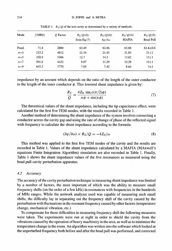
TABLE 1: Rs / Q of the test cavity as determined by a variety of methods.
Mode f(MHz) Q Factor Rs/Qcn) Rs/Qcn) Rs/Qcn) Rs/Qcn)
from Eq.(7) o<p/ow MAFIA Bead Pull
Fund. 71.4 2800 63.49 63.86 63.88 63.4±0.6
n=3 215.2 4812 21.16 21.45 21.85 21±1
n=5 358.9 5366 12.7 14.3 13.62 13±1
n=7 501.6 4422 9.07 11.29 10.29 10±1
n=9 645.2 1770 7.05 7.42 8.64 7±1
impedance by an amount which depends on the ratio of the length of the outer conductorto the length of the inner conductor 4>. This lowered shunt impedance is given by:
Rs 4Z0 sin2 ((n /2)4»
Q n 4> + sin(n4»(7)
The theoretical values of the shunt impedance, including the tip capacitance effect, werecalculated for the first five TEM modes, with the results recorded in Table 1.
Another method of determining the shunt impedance of the system involves connecting aconductor across the cavity gap and using the rate of change of phase of the reflected signalwith frequency to calculate the shunt impedance according to the formula:
(8cp/8w) x Rs/Q == -4Zo/w (8)
This method was applied to the first five TEM modes of the cavity and the results arerecorded in Table 1. Values of the shunt impedance calculated by a MAFIA (MAxwell'sequations Finite Integration Algorithm) simulation are also recorded in Table 1. Finally,Table 1 shows the shunt impedance values of the five resonances as measured using thebead pull cavity perturbation apparatus.
4.2 Accuracy
The accuracy ofthe cavity perturbation technique in measuring shunt impedance was limitedby a number of factors, the most important of which was the ability to measure smallfrequency shifts (on the order of a few kHz) in resonances with frequencies in the hundredsof MHz ranges. While the network analyzer used was capable of measuring such smallshifts, the difficulty lay in separating out the frequency shift of the cavity caused by theperturbation with fluctuations in the resonant frequency caused by other factors (temperaturechange, mechanical vibration, etc.)
To compensate for these difficulties in measuring frequency shift the following measureswere taken. The experiments were run at night in order to shield the cavity from thevibrations caused by the operation ofheavy machinery in the area, as well as to minimize thetemperature change in the room. An algorithm was written into the software which looked atthe unperturbed frequency both before and after the bead pull was performed, and corrected

NEW COAXIAL HOM DAMPER 215
the perturbed frequency shift at each step for a linearly changing unperturbed frequency.Furthermore, the speed at which the apparatus performed the bead pull was increased to arate of 2-3 seconds per step in order to minimize frequency fluctuations in the cavity andensure that any changes in the frequency would be linear and thus hopefully compensatedfor by the software. The speed of the system was ultimately limited by the rate at which thenetwork analyzer could sweep through a given set of frequencies - the system could onlyhave been made faster by losing detail in each sweep. With the above adjustments madeto the system, the frequency shifts in the cavity could be measured accurately down to thelevel of approximately 100 Hz. Several measurements were taken at each frequency, and theresults examined. The strongest resonances (particularly the fundamental frequency) couldbe measured to an accuracy of 1%. For some of the weaker higher-order mode resonances,the system could determine the shunt impedance to within 5-10%.
5 RESULTS OF MEASUREMENTS OF THE 6-INCH DAMPER AND CAVITY
5.1 Higher-order modes
The 6-inch higher-order-mode damper structure was attached to the open end of the quarterwavelength coaxial test cavity. Measurements were taken both with and without the homstructure attached in order to observe its effect on the shunt impedance of the overall system.
The combined cavity/damper structure had a fundamental resonant frequency of65.5 MHzwith the hom, a much lower frequency than the value of ~70 MHz for the cavity withoutthe damper structure. This 4 MHz reduction in the overall fundamental frequency is due primarily to the heavy capacitative tip loading of the damper structure. For the damper withoutthe hom, the tip loading was not quite as large and the fundamental frequency was found at65.9 MHz. The harmonics of the fundamental TEM mode were also observed at frequencieswhich were slightly reduced due to tip loading. In contrast to the reduced frequencies ofthe TEM modes, the frequency of the circumferential mode (TEI,I) at 714 MHz remainedbasically unchanged when the damper structure was added to the cavity.
The addition of the damper structure to the system not only altered the existing modesof the cavity, it also added two new sets of modes. The first set of new modes were thoseof the quarter-wavelength coaxial resonator made up of the damper itself, with the innerconductor terminating either on the hom or one of the disc structures. These modes occurredat frequencies of 600 MHz or higher. For this set of modes, the addition of the horn simplyadded one more resonance. The second set of modes introduced were those of the halfwavelength coaxial resonator made up of the combined test cavity and damper structure.In this case the inner conductors of the damper and cavity act as a single inner conductorbroken by a capacitance across the gap. These half-wavelength resonances were muchstronger with the hom in place, when the capacitance across the gap was larger. They werealso stronger for higher frequency harmonics, since for these the capacitance appears morelike a short circuit across the gap in the inner conductor, and the system becomes a betterhalf-wavelength resonator. These resonances were observed starting around 255 MHz withthe hom attached, and around 500 MHz with the damper alone, since in this case the lowerfrequency mode was too faint to detect.

216 D. JOFFE and A. MITRA
TABLE 2: Effect of HOM damper with the horn attached.
Frequency Unloaded Unloaded Rs Loaded Loaded Rs(MHz) Q Factor k(Q) Q Factor k(Q)
65A940±0.0001 2423±2 157±1 2341A±OA 148±1
195.692±0.002 2000±10 33±3 63.31±0.02 <1
255.547±0.001 1260±5 3.0±0.3 9.135±0.005 <0.02
339.629±0.003 1674±4 6.2±0.6 No resonance observed No resonance observed
416.650±0.001 1259.2±OA 1.9±0.2 9.6±0.2 <0.01
520.5281 ±0.0006 3168±5 0.22±0.02 45A±0.1 <0.003
644. 19±0.02 407±3 <0.1 No resonance observed No resonance observed
656.849±0.009 657±1 <0.05 No resonance observed No resonance observed
661.123±0.004 1281.7±0.3 <2 40.2±0.1 <0.06
714.295±0.007 724±3 <0.7 303.9±0.1 <0.3
TABLE 3: Effect of HOM damper with no horn.
Frequency Unloaded Unloaded Rs Loaded Loaded Rs
(MHz) Q Factor k(Q) Q Factor k(Q)
65.8665±0.0004 2041±3 96±2 2036±3 94±4
204.984±0.001 1759±6 32±3 38±1 <0.7
327.999±0.003 1182±1 7.3±0.7 6.8±0.1 <0.04
413.638±0.006 1150±20 1.0±0.7 39.0±0.2 <0.03
515.328±0.002 2210±1 <2 No resonance observed No resonance observed
571.63±0.05 1400±100 <6 No resonance observed No resonance observed
640.60±0.04 228±7 <1 No resonance observed No resonance observed
653.965±0.004 864.8±0.8 <0.5 38A5±0.03 <0.01
713.94±0.04 619±3 <2 300A±0.1 <1
For both of these new types of modes, the shunt impedances were much lower than that ofthe fundamental resonance. The largest shunt impedance of one of the new modes was 3 kQ,less than 2% of the impedance at the fundamental. All the new modes were damped stronglyonce the damper was fully loaded, and in no case did the new modes have impedances whichexceeded 100 Q when all four loads were attached. This is significant since it means thatthe addition of the damper structure did not add any modes for which the shunt impedanceacross the gap would be greater than 1 kQ in the fully damped system, and thus potentiallyresult in serious beam instabilities. It is also worth noting that the addition of the damperstructure did not add any new circumferential modes in the relevant frequency range (up to800 MHz).

NEW COAXIAL HOM DAMPER 217
5.2 Shunt Impedances
With the higher-order-mode damper structure attached to the cavity the frequency, Q factor,and shunt impedance of each mode (up to 800 MHz) was measured using the bead-pullapparatus, with and without the hom, and with and without all four loads attached. Theresults obtained with the hom attached are given in Table 2, those obtained without the homattached are given in Table 3. Note that the frequencies given in the tables are those of thevarious modes with no loads attached.
The damper was effective in damping the higher-order-mode resonances without stronglyaffecting the fundamental resonance both with and without the hom attached. At thefundamental frequency, the measured reduction in Q factor as a result of damping (which isa measure of the power lost) was 3% for the damper with the hom attached, and 0.3% for thedamper with no hom attached. Although this would seem to indicate that the filter withoutthe hom gives a better performance at the fundamental frequency, the power lost by the filterwith the hom could probably have been reduced by optimizing the capacitances betweenthe hom and the inner conductor and the hom and the first disc. The shunt impedances alsoremained relatively unchanged at the fundamental frequency, with the damper reducing thefundamental impedance by 6% with the hom attached, and by 2% with no hom.
At the higher-order TEM modes up to 800 MHz both damper designs were effectivelyable to damp both the Q factors and shunt impedances. The Q factors of these modes weredamped between 95% and 100% both with and without the hom, and in all cases the HOMshunt impedances were brought below 1 kQ.
With the hom attached the damper became effectively a seven- rather than a five-elementfilter. Although the seven-element filter gave sharper attenuation below the comer frequency,above it the response of both filters was essentially the same. Thus the presence of the hommakes very little difference to the capacity of the damper for the higher-order TEM modes.The damper had a much less dramatic effect on the non-TEM modes to which the high-passfilter was less able to couple effectively. For the TEI,1 mode found at 714 MHz the damperreduced the Q-factor of the resonance by approximately 50% (see Tables 2 and 3), bringingthe shunt impedance to below 1 kQ both with and without the hom.
Although adding the hom to the cavity did not significantly change the performance ofthe damper, it did cause one specific change in the pattern of the field across the gap. Figure 5shows the frequency shift (which is proportional to the square of the electric field strength)as the bead was pulled across the gap both with the hom attached and without. Althoughthe gap between the inner conductor and the first damper element was set to the same valuefor both configurations, the effective total gap of the cavity/damper structure with no homattached was larger, so that the discs were inside the overall gap rather than beyond it. Thechange in the field pattern caused by removing the hom was to distribute the field alongthe entire length of this new extended gap, while keeping the shunt impedance more or lessconstant.
6 HIGH POWER TEST OF THE HOM DAMPER
The full-scale HOM damper with the hom attached, as shown in Figure 3, was installedon the ferrite-tuned Booster cavity. Prior to the high power test, an attempt was made to

218 D. JOFFE and A. MITRA
18000
16000
14000
12000
10000
8000
6000
4000
2000
o F~-o~:CO::~~~~~~+++:H+H~:r:mm.rr~rn:ri~~~m:r!!!!r~!!r!rrrn:rm:rrrr::[D-2000 N ~ ;;; ~ ~ ~ ~ ~ :Q :g r::: ~ 00 ~ 0: 8. 5 (3 ..0
FIGURE 5: Field profile along damper/cavity axis with and without horn attached.
3500 . Unloaded
3000 1tA Loaded
2500(J
"'C 2000
I!!:::J
0 1500CD I:E •1000
II I500 ! I 1 I0
L() 0- L() co~
,........~ L() 0- L.() N
~I.f)
eO L.() ,........ 0: 0- 0= ~ "" L() 0 -0
"" ~ co a c:> C"'5 L() co ~ C"'5 c:> 1.0 C"'50= ~ l() N c:i C"")~
0- L.() -0l() N N N ,........~ -0 0- 0-
C"")
Frequency MHz
FIGURE 6: Q measurement of the ferrite tuned cavity with damper installed and horn attached.
estimate the shunt impedance of the damper-cavity system using the perturbation technique.Since the resonant frequency of the ferrite-tuned cavity was governed by the bias current,the stability of this current dictated the stability of the resonant frequency. Unfortunately,the shift in the resonant frequency due to bias current variation was more than an order ofmagnitude greater than the frequency shift expected from perturbation measurements, henceshunt impedance measurements of the combined damper-cavity configuration could not becarried out by the perturbation technique. However, the Q factors and shunt impedances ofthe resonances or higher-order modes of the damper alone were measured and are shown inTable 4. The Q factors of all the higher-order modes were significantly damped when thedamper was terminated with 50 Q loads, with the exception of a circumferential (TEI,I)mode at 460 MHz. The undamped and damped Q factors of the cavity-damper configurationare shown in Figure 6.
A hat was added to the inner conductor of the ferrite-tuned cavity at the gap end to helpform the first capacitance of 15 pF of the filter. The gap between the cavity inner conductor
NEW COAXIAL HOM DAMPER 219
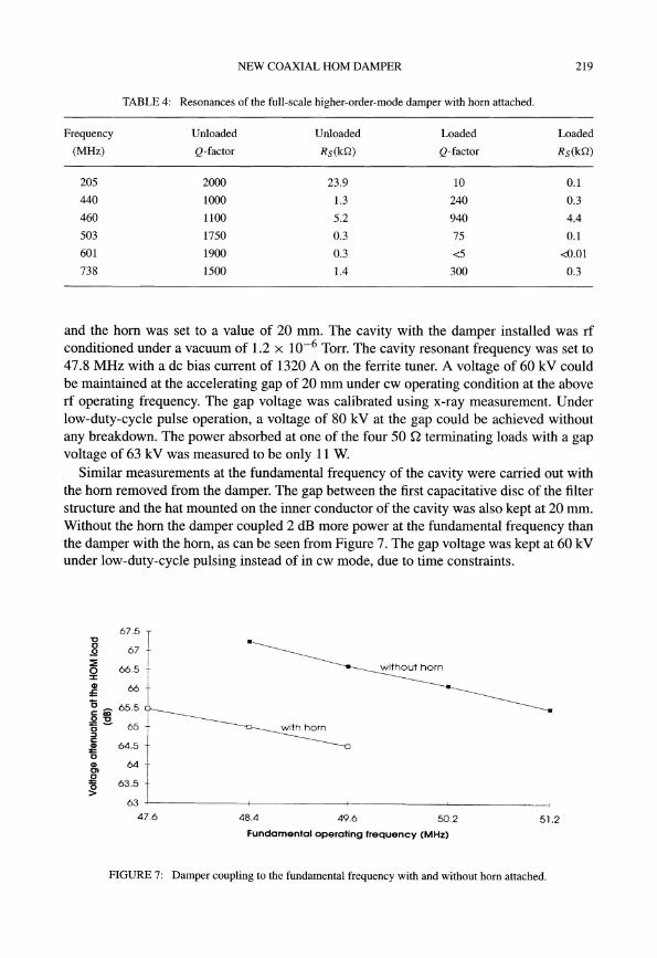
TABLE 4: Resonances of the full-scale higher-order-mode damper with horn attached.
Frequency Unloaded Unloaded Loaded Loaded
(MHz) Q-factor Rs(kQ) Q-factor Rs(kQ)
205 2000 23.9 10 0.1
440 1000 1.3 240 0.3
460 1100 5.2 940 4.4
503 1750 0.3 75 0.1
601 1900 0.3 <5 <0.01
738 1500 1.4 300 0.3
and the hom was set to a value of 20 mm. The cavity with the damper installed was rfconditioned under a vacuum of 1.2 x 10⁻⁶ Torr. The cavity resonant frequency was set to47.8 MHz with a dc bias current of 1320 A on the ferrite tuner. A voltage of 60 kV couldbe maintained at the accelerating gap of 20 mm under cw operating condition at the aboverf operating frequency. The gap voltage was calibrated using x-ray measurement. Underlow-duty-cycle pulse operation·, a voltage of 80 kV at the gap. could be achieved withoutany breakdown. The power absorbed at one of the four 50 Q terminating loads with a gapvoltage of 63 kV was measured to be only 11 W.
Similar measurements at the fundamental frequency of the cavity were carried out withthe hom removed from the damper. The gap between the first capacitative disc of the filterstructure and the hat mounted on the inner conductor of the cavity was also kept at 20 mm.Without the hom the damper coupled 2 dB more power at the fundamental frequency thanthe damper with the hom, as can be seen from Figure 7. The gap voltage was kept at 60 kVunder low-duty-cycle pulsing instead of in cw mode, due to time constraints.
67.5
51.250.2
without horn
49.6
with horn
48.4
'0
~ 67
~ 66.5%
~ 66
~ cc 65.50'0lS - 65::Jc:~ 64.5cCD 64C),g~ 63.5
63 ~-------+-------+-------~----------1
47.6
Fundamental operating frequency (MHz)
FIGURE 7: Damper coupling to the fundamental frequency with and without horn attached.

220
7 DISCUSSION
D. JOFFE and A. MITRA
Accurate knowledge of the shunt impedance of this type of filter structure when attached tothe resonant cavity is of the utmost importance in predicting its usefulness as a higher-ordermode damper. Emphasis was given to measuring shunt impedances, as opposed to simplythe Q-factor of the resonance, in determining damper performance, and the perturbationmeasurement outlined in section 3 proved to be the most accurate and effective methodof determining these impedances. Perturbation measurements of the shunt impedances ofthe combined cavity/damper system compared well with results obtained from MAFIAsimulations run on the same system. 12
Some conclusions may be drawn from the measurements described in sections 5 and 6.The damper is seen to be effective up to the 800 MHz range both with and without thehom attachment, meaning that the hom may not be entirely necessary to shield the multiplegap structure from the beam. The higher-order modes which were least affected by thedamper (damped by only 50% when the loads were attached) were the circumferentialmodes of the structure itself, which tended to limit the pass band of the filter. It shouldbe possible to suppress these circumferential modes by cutting radial slots on the discs orcutting the discs into halves (this option makes the design of water cooling difficult). Toimprove the filter performance further, we would like to examine the upper limit of thepass-band. This limit corresponds roughly to the frequency at which the rods act as quarterwavelength resonators; beyond this frequency the rods no longer behave as proper inductorsin the filter circuit and reducing the lengths of these inductors would increase the pass-bandlimit. For the full scale HOM damper the A/4 resonances of the inductors loaded by theirrespective capacitive discs were close to 700 MHz. Furthermore, the rods that connect thelast disc to the 50 Q terminating loads should be as non-inductive as possible, so it wouldbe advantageous to minimize the lengths of these final connecting rods. There is also roomfor further optimization of the filter components with respect to the lower pass-band rippleof the filter.
8 CONCLUSION
Both signal-level and high-power tests show that this new type of coaxial filter performs wellas a higher-order-mode damper. The hom version is theoretically slightly more attractivesince given the same comer frequency the filter can be designed to couple even less powerat the fundamental. However, the measured voltage attenuation of 65 dB at 48.3 MHz ismore than satisfactory even without the hom. This type of damper does not suffer fromexcessive coupling of power at the fundamental frequency as is evident from the measuredloss of Q of only 4% at 48.3 MHz with the damper attached.
This kind of higher-order-mode damper employing a high-pass filter in a coaxial form isvery suitable for single gap cavities similar to the one described in this paper; being coaxial,it becomes an integral part of the resonant cavity. The same damper can be mounted outsidethe cavity if adequate capacitive coupling to the beam gap can be achieved.

ACKNOWLEDGEMENTS
NEW COAXIAL HOM DAMPER 221
The authors would like to thank Michael Craddock for his invaluable support, and RogerPoirier for his insight and discussion on the damper and cavity system. Also, they wouldlike to thank Peter Harmer for his assistance in Autocad drawing and fabrication.
REFERENCES
1. M.K. Craddock, "The Status of the KAON Project," ICFA Seminar on Perspectives in High Energy Physics,DESY,1993.
2. KAON Factory Proposal, (ed.) M. Craddock, "Accelerator System", Chapter 4, TRIUMF, 1985.
3. T. Enegren, R. Poirier, et aI., "Higher Order Mode Damping in KAON Factory RF Cavities", Proc. of the1989 IEEE Particle Accelerator Conf., 1, 196-198 (1989).
4. W.R. Smythe, T.A. Enegren and R.L. Poirier, "A Versatile RF Cavity Mode Damper," Proc. of the 2ndEuropean Particle Accelerator Conf., 1, 976-978 (1990).
5. A.K. Mitra, "Higher Order Mode Dampers for the KAON Booster Cavity," Proc. of the 1993 ParticleAccelerator Conf., 2, 974-976, (1993).
6. A.K. Mitra, "A New Concept of a Higher-Order-Mode Damper for the KAON Booster Cavity," Proc. ofthe 4th European Particle Accelerator Conf., 3, 2158-2160, (1994).
7. T.A. Enegren, "Measurement ofRF Shunt Impedance", TRIUMF, Design Note, 89-K104, 1989.
8. H. Klein, N. Merz, et aI., "Field Distribution, Power Losses and Parameter Optimization of HelicalAccelerator Structures", Particle Accelerators, 3, 235-244, (1972).
9. H. Klein, "Basic Concepts I", Proc. of the 1991 CERN Accelerator School, 1,97-124, (1991).
10. S.W. Kitchen and A.D. Schelberg, "Resonant Cavity Field Measurements", Journal ofApplied Physics, 26,5, 618-621, (1954).
11. D. Joffe, "Cavity Perturbation Measurements of the Shunt Impedance of a Tuned Resonator with HigherOrder-Mode Damping", M.Sc. Thesis, University of British Columbia, 1994.
12. E. Zaplatin, "Studies of the TRIUMF KAON Factory Booster Cavity HOM Damper", Proc. of the 4thEuropean Particle Accelerator Conf., 3, 2161-2163 (1994).