performance of the streetmapper mobile lidar mapping system
TRANSCRIPT

Kremer, Hunter 215
Performance of the StreetMapper Mobile LIDAR Mapping System in “Real World” Projects
JENS KREMER, Kreuztal GRAHAM HUNTER, Nottingham
ABSTRACT Static terrestrial laser scanning and airborne laser scanning from helicopters and fixed wing aircraft are widely used tools for the 3D data capturing of smaller scenes and large areas, respectively. Both methods have their limitations for projects that include the rapid and cost effective capturing of 3D data from larger street sections, especially if these sections include tunnels or if dense point coverage of the facades of the neighboring architecture is required. To extend the applicability of laser scanning to these kinds of projects, terrestrial cinematic laser scanning can be used. In this paper the components, the workflow and the performance of the Mobile Mapping system “StreetMapper” are described.
1. INTRODUCTION
The performance and availability of modern 3D laser scanning systems has created a demand for a system that can survey many kilometres of highway very rapidly. Airborne laser scanning can offer this type of data but aircraft operations are expensive. Also this type of data can lack detail due to the distance above the area to be surveyed. Terrestrial 3D laser scanners are commonly employed for highway and building surveys nowadays, however, these instruments are slow, therefore costly, when large areas need to be surveyed. Mounting a 3D scanner on the roof of a vehicle can improve the speed and productivity but there are still disadvantages such as uneven point spacing and the time taken to accurately geo-reference each 3D scan. For large surveys, over 100 individual scan positions must be geo-referenced which causes significant data management problems.
Figure 1
Photogrammetric Week '07 Dieter Fritsch (Ed.) Wichmann Verlag, Heidelberg, 2007

216 Kremer, Hunter
The StreetMapper mobile laser scanning system was developed initially to fill a demand for measurement and recording of highway assets, but has since been developed for other applications. The system uses four 2D laser scanners integrated with a high performance GPS/inertial navigation system. The system is easily deployed on a range of different vehicles and the first StreetMapper system has been operating since early 2005. The significant commercial advantage of the system is that no traffic management is required to complete highways surveys to an accuracy of 30mm. Highway surveying using videogrammetry, supported by GPS/INS systems, have been well used in many parts of the world. However, there are significant challenges in creating 3D data products with minimal human data processing. Some of these systems are now adding laser scanners to improve data processing workflows. Several vehicle based laser scanning systems have been built in recent years (e.g. Talaya et al. 2004, Grinstead et al. 2005, Pfaff et al. 2007). Most of these systems were unique installations and developed mainly to demonstrate the general applicability of this technology. The StreetMapper is the first fully integrated, commercially available system of its type. The performance objectives of the Mobile Mapping system “StreetMapper” are: • Complete eye safe operation • Operational speeds up to 80 km/h • Operation of additional video cameras • Full field of view • Operation in urban environments and under tree cover It is noted that there are the following limitations of such a Mobile Mapping system: • The field of view is line of sight from the vehicle path, so only the fronts of buildings are
surveyed. • The point density decreases with driving speed (similar to airborne lidar), so highest point
density is captured at slow driving speeds such as 15 km/h.
2. SYSTEM COMPONENTS
In order to meet the performance objectives, stated above, an integrated “multi-sensor” system is required. The full 360° field of view is reached by operating four 2D-laser scanners simultaneously (Figure 2).
Figure 2: Field of view of the single laser scanners.
To enable an eye safe operation and a sufficient point density at high operating speeds the LMS-Q120 instrument from Riegl Laser Measurement Systems, Horn, Austria was selected. The

Kremer, Hunter 217
mounting position and angles are carefully optimized to provide maximum coverage with some overlapping data between each adjacent scanner. The interpretation of the data is improved by the integration of one or more video cameras. For projects where high quality images are needed, the integration of a high resolution digital still camera has been tested successfully. In addition to the customary GNSS and IMU, the challenging GNSS conditions in urban areas and areas with tree cover lead to the need of an additional speed sensor. For such a “multi sensor system” the correct time synchronization of all sub sensors is crucial. This synchronization is reached by tagging all collected data with the exact GPS time. The
TERRAcontrol computer gets the actual time from the GNSS receiver and distributes a time pulse together with a time stamp to all used sensors.
2.1. Lidar
The design of the multi-sensor integration allows the selection of the most appropriate laser scanning (often called lidar) sensor for the end-user’s application. For most highway and urban surveying, the LMS-Q120 has a good performance for the price. The maximum range is 150m and the accuracy is 25mm. For long range surveying, which may be required for coastline surveys, the LMS-Q240 (450m range) or the LMS-Q560 (700m range) can be used. These different sensors have been integrated for testing under different conditions.
2.2. Video System
Depending on the survey application, two different imaging systems can be operated with the StreetMapper: For most of the StreetMapper applications, the main task of the imaging data is to enable a better visual interpretation of the data. In this case, a normal consumer video camera system is used. The data of this video camera is time tagged by the TERRAcontrol and can be synchronized with the laser scanner data. If the text on street signs should be visible in the video, the camera can be mounted independently from the other sensors. Although the rigid connection to the IMU is missing in this case, the information about the position and orientation of the camera is still good enough for the given task. Figure 4 shows a street scene in Germany on the left side captured by the video camera and on the right side the lidar point cloud seen from the same perspective.
Figure 3: The StreetMapper sensor platform.

218 Kremer, Hunter
Figure 4: Street scene captured with video camera and the same scene in the lidar point cloud.
If the camera should create image data of higher quality, a digital still camera can be operated. To take the full benefit of the orientations from the GNSS/IMU system, this camera is mounted together with the other sensors on the rigid platform.
Figure 5 shows data that was captured with a StreetMapper together with a DigiCAM K14 (based on a Kodak DCS pro 14n). The camera image was overlaid on the lidar point cloud using the software PHIDIAS from PHOCAD Ingenieurgesellschaft mbH, Aachen, Germany.
2.3. GNSS/IMU
Like in airborne LIDAR mapping, the accuracy of cinematic terrestrial LIDAR mapping depends mostly on the exact determination of the position and orientation of the laser scanner during data acquisition. Nevertheless, the different conditions in a land vehicle compared to an aircraft lead to different requirements for the used GNSS/IMU system: The GNSS conditions in a land vehicle are deteriorated by multipath effects and by shading of the signals caused by trees and buildings. On the other hand, the distance between the scanner and the measured object is typically some ten meters, compared to several hundred meters for airborne laser scanning. Therefore the contribution of the GNSS positioning error to the overall error budget is much larger than the contribution of the error from the attitude determination.
Figure 5: Digital camera images overlaid on the lidar pointcloud.

Kremer, Hunter 219
To gain a better aiding of the inertial navigation system during periods of poor GNSS, the GNSS/IMU navigation system for the StreetMapper is extended by an additional speed sensor. Among other benefits in the processing of the navigation data, the speed sensor slows down the error growth in periods of missing GNSS, like in tunnels or under tree cover. The TERRAcontrol GNSS/IMU system used for position and attitude determination inside the StreetMapper consists of the following components: Inertial Measurement Unit The TERRAcontrol is using the IGI IMU-IId fiber optic gyro based IMU. This IMU is successfully operated with a large number of airborne LIDAR systems and aerial cameras. It’s angular accuracy of below 0.004° for the roll and pitch angle can not be fully exploited for the short scanning distances in this application, but the high accuracy strongly supports the position accuracy in areas of weak or missing GNSS. GNSS Receiver The TERRAcontrol uses the NovAtel OEMV-3 card from NovAtel Inc, Calgary, Canada. Besides GPS, this receiver supports GLONASS and OmniSTAR HP real time corrections. In the standard configuration, the StreetMapper uses GPS and GLONASS. Since the system is optimized for data processing in post processing mode, the real time corrections from OmniStar HP are usually not used. TERRAcontrol Computer The TERRAcontrol stores the raw data from the IMU, the GPS receiver and the speed sensor. It also provides the used laser scanners and digital cameras with accurate GPS time stamps for later synchronization of all data streams in post processing. With the user interface the operator can start and stop the operation of TERRAcontrol, access the actual GNSS status and synchronously start and stop the different laser scanners. The navigation raw data is stored on a PC card for later post processing. GNSS/IMU Post Processing Software The TERRAoffice software package provides all functions necessary for handling and processing the collected navigation data. Besides the routines for calculating the exact position and orientation of the sensor platform, it contains the transformation of the results into local mapping systems and various quality control tools.
2.4. System Integration
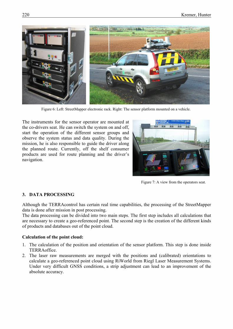
The StreetMapper system is offered either as a turnkey survey vehicle where all system components are fixed mounted, or as a combination of the sensor platform together with a movable electronic rack for versatile operation in different vehicles. The overall weight of the system of about 180 kg (incl. four scanners) and the small size allows the operation on normal passenger cars like in Figure 6.
220 Kremer, Hunter
Figure 6: Left: StreetMapper electronic rack. Right: The sensor platform mounted on a vehicle.
The instruments for the sensor operator are mounted at the co-drivers seat. He can switch the system on and off, start the operation of the different sensor groups and observe the system status and data quality. During the mission, he is also responsible to guide the driver along the planned route. Currently, off the shelf consumer products are used for route planning and the driver’s navigation.
3. DATA PROCESSING
Although the TERRAcontrol has certain real time capabilities, the processing of the StreetMapper data is done after mission in post processing. The data processing can be divided into two main steps. The first step includes all calculations that are necessary to create a geo-referenced point. The second step is the creation of the different kinds of products and databases out of the point cloud. Calculation of the point cloud: 1. The calculation of the position and orientation of the sensor platform. This step is done inside
TERRAoffice. 2. The laser raw measurements are merged with the positions and (calibrated) orientations to
calculate a geo-referenced point cloud using RiWorld from Riegl Laser Measurement Systems. Under very difficult GNSS conditions, a strip adjustment can lead to an improvement of the absolute accuracy.
Figure 7: A view from the operators seat.

Kremer, Hunter 221
Creation of final products: 3. The intensities from the different laser scanner are normalized to enable the different scans to be
merged into one dataset. 4. The dataset is split into project tiles of a size that can be handled by the lidar data analysis
software. 5. The points in the cloud are classified to be ground points, vegetation, buildings and so forth. 6. The geo-referenced and classified point cloud can then be used as the basis of products such as:
• 3D city models with detailed façade and street level information. • Digital terrain models, especially for rapid volume determination for the mining industry. • Highway surveying where level, gradient and edge of carriageway information is extracted. • Asset Management Databases for highway authorities (for example, sign posts and street
furniture) or utilities (for example, heights of wires over the road). • Change detection for military and security forces.
3.1. System Calibration
The relative position of the different sensors to the IMU can be measured directly at the sensor assembly. The relative orientation, or misalignment, has to be determined from the data. For this misalignment calibration, features like street marking or house corners are captured in multiple paths. Certain target structures allow separate determination of the three misalignment angles. Due to the rigid mounting of the laser scanners and the IMU, the misalignment calibration does not change noticeably between different missions.
4. SYSTEM ACCURACY
For a Mobile Mapping vehicle like the StreetMapper, the accuracy of the results has to be quoted in two different ways:
4.1. Relative Accuracy
The relative accuracy describes the spread of the measurements between two points in the same region, taken in a short time period. This error is dominated by the noise of the single laser scanner measurements. For the StreetMapper the relative accuracy is about 2.5cm. It should be noted, that the accuracy of the measurement of the distance between two features in the measured scenery is not equal to this relative accuracy. This accuracy is strongly influenced by the possibility to determine the position of the features in the point cloud. Depending on the shape of the feature and on the point density, this accuracy can be better or worse than the given relative accuracy. For the operation of the StreetMapper, both, the relative accuracy and the accuracy to measure the distance between two features is nearly independent of the short term GNSS conditions. In periods of missing GNNS, only the absolute accuracy is decreasing!
4.2. Absolute Accuracy
The absolute accuracy is the accuracy of laser measurements in a local mapping coordinate system. This absolute accuracy is dominated by the quality of the GNSS solution. Under good conditions this accuracy is about 3cm, under difficult conditions it can be go up to 0.5m.

222 Kremer, Hunter
This behavior can be exploited in applications where only the relative position of features is of interest, and not the absolute position in a mapping coordinate system. These could be applications like distance measurement inside tunnels (see Figure 8), or in the planning of driving routes for large and heavy loads.
Figure 8: Measurement of a tunnel profile.
5. STREETMAPPER PROJECTS
5.1. Project “Red House Farm”
An evaluation of the vertical accuracy of the StreetMapper has been done in the “Red House Farm Test” in Newcastle upon Tyne, UK (Barber 2006, Hunter et al. 2006) in May 2006. For this test, more than 300 reference points have been established with Rapid Static Differential GPS. The elevation of the directly measured reference points was compared to the elevation calculated from StreetMapper data. This comparison was done for two different driving days. The RMS of the differences was 19mm and 23mm respectively. This result demonstrates that due to the averaging effect of the surface modeling, the reachable accuracy of a surface model created by StreetMapper data is higher than the accuracy of the single laser shot (which is 25 mm for the StreetMapper system).
5.2. Project “Borlange”
Another test of the StreetMapper accuracy in measuring the absolute height levels of a street section was conducted in January 2006 in Borlange, Sweden, where 24 reference points were accurately measured in the project area. The distance between the modeled surface and the measured points was calculated. The left part of Figure 10 shows the distribution of the reference points in the project area. In the right side of this figure a cross section through the marked fraction of that data set is selected. The two black squares are two reference points. Four of the measured points were measured under snow cover and these points were not taken into account for this test.
Figure 9: Distribution of the vertical offsets.
-30
-20
-10
0
10
20
30
0 5 10 15 20
point number

Kremer, Hunter 223
The distribution of the vertical offsets is shown in Figure 9. The standard deviation of the vertical distances is 15mm.
5.3. Measurement of Overhead Telephone Cables
Because of the full field of view and the high relative accuracy the StreetMapper can be used to measure overhead cables quickly and accurately. In October 2005, the minimal distance of overhead telephone cables to the ground was measured by the StreetMapper and a total station survey instrument. Measurements were taken at the same time to ensure the same atmospheric conditions. To find minimum distance in the lidar data set, a catenary curve was fitted to the points that were classified as wire points. Then the distance from the lowest point of this curve to a plane fitted to a cluster of points on the ground below was measured. For the total station measurement the lowest point of the cables was selected visually and then the vertical distance to the ground was measured. The comparison of the results of 25 wires from 9 different sites showed standard deviation of 59 mm. The maximum difference was 104 mm.
Figure 11: Photo of overhead telephone wires.
Figure 10: Distribution of the measured reference points in the project area.

224 Kremer, Hunter
Figure 12: Measurement of the minimum vertical distance.
Compared to the relative accuracy of the StreetMapper and of the total station measurement, the accuracy looks relatively poor, but Figures 11 and 12 show the reason for these values. The difficulty is not to define the catenary curve of the wire, but the position of the minimum distance to ground. The ground is not a nicely defined plane, but a real street with deformations, with curb and with slope. Besides the greater operating speed and better accuracy, the StreetMapper measurements have the advantage, that they are not biased to measure a longer minimum distance rather than a shorter one. This is the case for the traditional way of checking the wire height (Figure 13). If the minimum point is not exactly found, or if the pole is not really vertical, the measurements are always over-estimating the free space over the road.
6. CONCLUSION
Accuracy levels of better than 30mm in good GPS conditions make the StreetMapper system practical for many mapping applications, such as for highway surveying and for making exact measurements of clearances under overhead wires. The projects illustrated here show that the expected accuracy can be achieved in a variety of real world projects. With the accuracy results shown here, we have demonstrated that this technology is ready for widespread adoption for a variety of surveying and mapping tasks.
Figure 13: Measurement with a pole.

Kremer, Hunter 225
7. ACKNOWLEDGEMENTS
The authors would like to acknowledge to contribution to third parties for providing assistance in accuracy trials. The “Red House Farm” tests were conducted in conjunction with David Barber and Jon Mills of University of Newcastle upon Tyne and Sarah Smith-Voysey of Ordnance Survey. The “Borlange” tests were conducted in conjunction with Magnus Larson of WSP Civils.
8. REFERENCES
Hunter, G., Cox, C., Kremer, J. (2006): Development of a Commercial Laser Scanning Mobile Mapping System – StreetMapper, Second International Workshop The Future of Remote Sensing, Antwerp, October 17-18, 2006.
Hunter, G. (2006): Accurate Terrestrial Laser Scanning from a Moving Platform, Geomatics World,
PV Publications, July/August 2006. Grinstead, B., Koschan, A., Page, D., Gribok, A. and Abidi, M.A. (2005): Vehicle-borne Scanning
for Detailed 3D Terrain Model Generation, SEA Commercial Vehicle Congress, Chicago, November 2005, SAE Technical Paper 2005-01-3557.
Talaya, J., Alams, R., Bosch, E., Serra, A., Kornus, W. and Baron, A. (2004): Integration of a
Terrestrial Laser Scanner with GPS/IMU Orientation Sensors, XXth ISPRS Congress, Istanbul, 12-23 July 2004.
Pfaff, P., Triebel, R., Stachniss, C., Lamon, P., Burgard, W. and Siegwart, R. (2007): Towards
Mapping of Cities, Proc. of the IEEE International Conference on Robotics and Automation (ICRA 2007), Rome, 2007.