performance of mat (or raft) foundations due to
TRANSCRIPT

PERFORMANCE OF MAT (OR RAFT) FOUNDATIONS DUE TO SETTLEMENT PROBLEM
ROZAIMI BIN MOHD NOOR
A project report submitted in partial fulfillment of the
Requirements for the award of the degree of Master of Engineering (Civil-Geotechnics)
Faculty of Civil Engineering Universiti Teknologi Malaysia
OCTOBER 2009

Dedicated to my beloved mother, father, wife, sons, daughters, lecturers and friends.
Thanks for everything.
May Allah bless all of you

ACKNOWLEDGEMENT
In the name of Allah S.W.T the moist gracious and most merciful, Lord of the
universe. Alhamdulillah, with His permission, the project report has been completed.
Praise to Prophet Muhammad S.A.W., His Companions and to those on the path as
what He preached upon, might Allah Almighty keep us His blessing and tenders.
In completing this Master project, I have met many people regarding the collection of
data, data analysis and also the report writing. I would like to take this opportunity to
express my sincere appreciation to all people and organization that had contributed
towards the preparation of this final project.
Firstly, I wish to thank my respectful supervisor, Dr. Nazri Ali for his full support and
complete guidance and also for spending his precious time to supervise my works.
Without his assistance and supervision, I don’t think I can complete the master project
properly. I would not forget his invaluable guidance and advices throughout this
project
Secondly, my sincere appreciation also extends to all my lecturers, colleagues and
others who have provided assistance in various occasions. Last but not least, not to
forget the full support that has been given by my family members during my study.

ABSTRAK
Penilaian tanah perlu dilakukan bagi mengetahui tentang kekuatan sebenar
keupayaan sesuatu tanah sebelum sebarang keputusan penukaran sistem asas sesuatu
bangunan dapat dilaksanakan. Kertas projek ini membincangkan isu berkaitan
penukaran sistem asas ‘piling’ kepada sistem asas rakit bagi sebuah blok asrama di
projek Asrama Berkelompok Yayasan Terengganu, Besut. Antara faktor lain yang
diambil kira adalah dari aspek kos dan masa. Aspek kos menjadi isu utama kepada
pemilik/klien sesuatu projek kerana ianya akan mempengaruhi budget yang telah
diperuntukkan. Manakala aspek masa pula akan menentukan tempoh pembinaan dapat
disiapkan, adakah lebih cepat atau sebaliknya yang akan menguntungkan pihak
kontraktor juga. Akhirnya aspek kejuruteraan geoteknikal akan dinilai untuk
memastikan kawasan kes tersebut boleh mengadaptasi perlaksanaan cadangan asas
yang baru tanpa melibatkan sebarang risiko kegagalan berkaitan dengan kekuatan
tanah.

ABSTRACT
Soil evaluation must done to find out of real strength capacity before any
conversion decision is taken to change the foundation system of building. This project
paper discussed an issue relating foundation system conversion from ‘piling' to mat
(raft) system for a hostel block in the Project of Asrama Berkelompok Yayasan
Terengganu, Besut. Among other factors taken into account is from cost and time
aspect. Cost aspects be major issue to owners / a project client because it will affect
budget were appropriated. While time aspect also will determine able construction
period completed, do quicker or otherwise will benefit contractor also. Finally
geotechnical engineering aspect will be evaluated to be sure the case study can adapt a
new of foundation proposal to be implement without involving any risk of failing
relates to the strength of soil.

TABLE OF CONTENTS CHAPTER TITLE PAGE
TITLE PAGE i
DECLARATION ii
DEDIDATION iii
ACKNOWLEDGEMENTS iv
ABSTRACT v
ABSTRAK vi
TABLE OF CONTENTS vii
LIST OF TABLE x
LIST OF FIGURES xi
LIST OF SYMBOLS xiii
LIST OF APENDICES xv
I INTRODUCTION
1.1 Background 1
1.2 Problem Statement 3
1.3 Objective of the Study 4
1.4 Scope of the Study 4

II LITERATURE REVIEW
2.1 Computational Geotechnics and Soil – Foundation – Structure
Interaction 5
2.1.1 Introduction 5
2.1.2 PLAXIS 6
2.2 Analysis and Design of Mat (or Raft) Foundations 6
2.2.1 Advantages of Using Shallow 6
2.2.2 Disadvantages of Using Shallow 7
2.2.3 Combined Footing 7
2.2.4 Types of Mat Foundation (or Raft) Foundations 8
2.2.5 To Design a Mat (or Raft) Foundation 10
2.3 Bearing Capacity of Mat (or Raft) Foundations 11
2.3.1 Introduction 11
2.3.2 Major point for Bearing Capacity of Raft
(or Mat) Foundation 12
2.3.3 Calculation and Estimation Bearing Capacity of Mat
(or Raft) Foundation 14
2.4 Settlement of Mat (or Raft) Foundation 20
2.4.1 Introduction 20
2.4.2 Compressibility and Settlement 21
2.4.2.1 Estimation of Immediate Settlement in Soil 21
2.4.2.2 Elastic Properties and In Situ Parameters 25
2.4.5 Settlement Analysis 27
2.4.5.1 Stress Distribution in Subsurface Soils
Due to Foundation Loading 27
2.4.6 Calculation and Estimation Settlement
of Mat (or Raft) Foundations 30
2.4.6.1 Immediate Settlement 31
2.4.7 Compensated Foundation 34
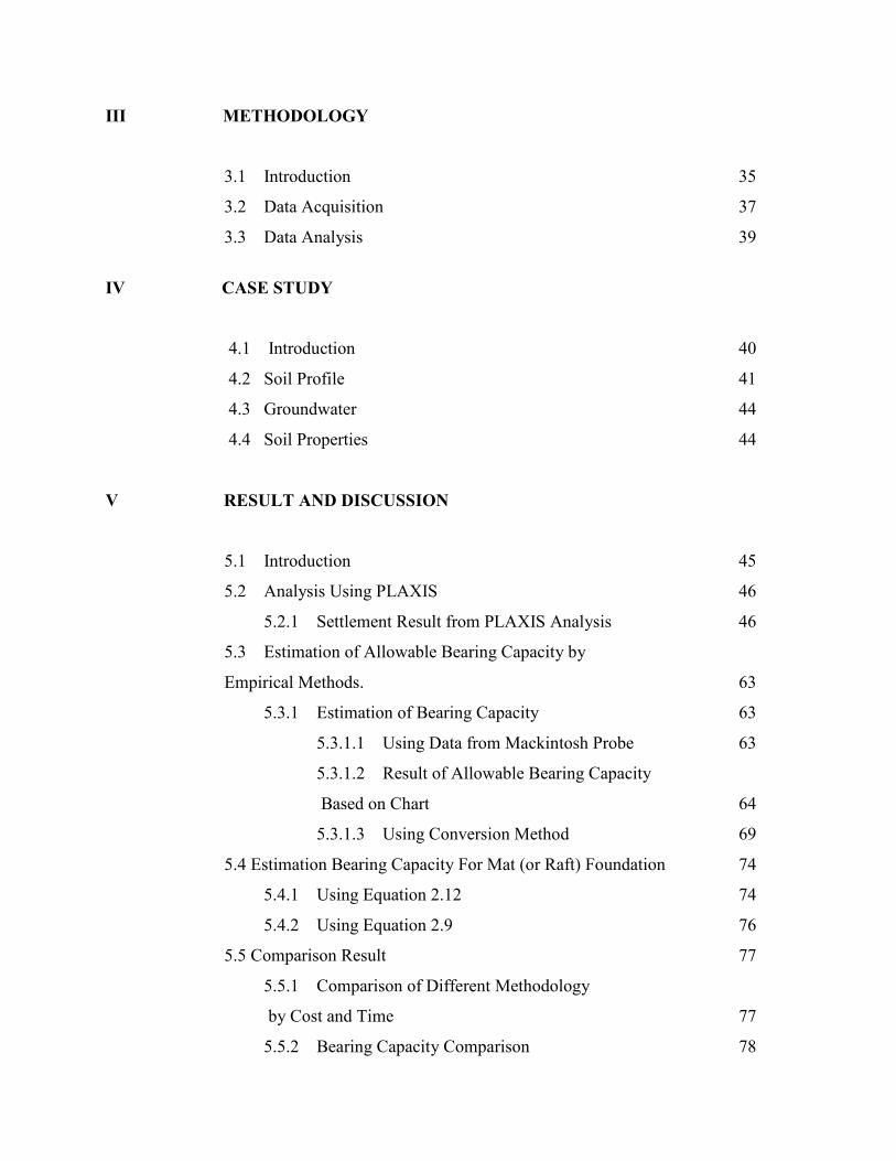
III METHODOLOGY
3.1 Introduction 35
3.2 Data Acquisition 37
3.3 Data Analysis 39
IV CASE STUDY
4.1 Introduction 40
4.2 Soil Profile 41
4.3 Groundwater 44
4.4 Soil Properties 44
V RESULT AND DISCUSSION
5.1 Introduction 45
5.2 Analysis Using PLAXIS 46
5.2.1 Settlement Result from PLAXIS Analysis 46
5.3 Estimation of Allowable Bearing Capacity by
Empirical Methods. 63
5.3.1 Estimation of Bearing Capacity 63
5.3.1.1 Using Data from Mackintosh Probe 63
5.3.1.2 Result of Allowable Bearing Capacity
Based on Chart 64
5.3.1.3 Using Conversion Method 69
5.4 Estimation Bearing Capacity For Mat (or Raft) Foundation 74
5.4.1 Using Equation 2.12 74
5.4.2 Using Equation 2.9 76
5.5 Comparison Result 77
5.5.1 Comparison of Different Methodology
by Cost and Time 77
5.5.2 Bearing Capacity Comparison 78
VI CONCLUSIONS AND RECOMMENDATIONS
6.1 Conclusions 79
6.2 Recommendations 80
REFERENCES APPENDIX
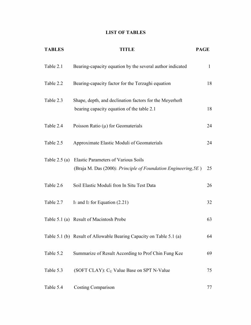
LIST OF TABLES
TABLES TITLE PAGE
Table 2.1 Bearing-capacity equation by the several author indicated 1
Table 2.2 Bearing-capacity factor for the Terzaghi equation 18
Table 2.3 Shape, depth, and declination factors for the Meyerhoft
bearing capacity equation of the table 2.1 18
Table 2.4 Poisson Ratio (µ) for Geomaterials 24
Table 2.5 Approximate Elastic Moduli of Geomaterials 24
Table 2.5 (a) Elastic Parameters of Various Soils
(Braja M. Das (2000). Principle of Foundation Engineering,5E ) 25
Table 2.6 Soil Elastic Moduli fron In Situ Test Data 26
Table 2.7 I1 and I2 for Equation (2.21) 32
Table 5.1 (a) Result of Macintosh Probe 63
Table 5.1 (b) Result of Allowable Bearing Capacity on Table 5.1 (a) 64
Table 5.2 Summarize of Result According to Prof Chin Fung Kee 69
Table 5.3 (SOFT CLAY): CU Value Base on SPT N-Value 75
Table 5.4 Costing Comparison 77

Table 5.5 Time Comparison 77
Table 5.6 Summarize of Comparison 78
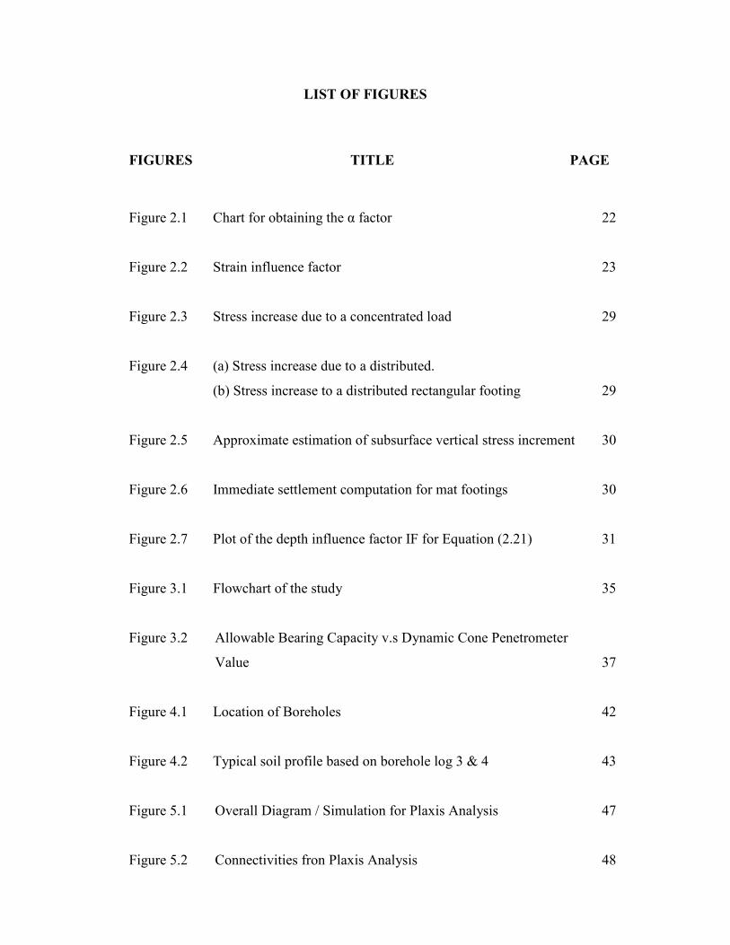
LIST OF FIGURES
FIGURES TITLE PAGE
Figure 2.1 Chart for obtaining the α factor 22
Figure 2.2 Strain influence factor 23
Figure 2.3 Stress increase due to a concentrated load 29
Figure 2.4 (a) Stress increase due to a distributed.
(b) Stress increase to a distributed rectangular footing 29
Figure 2.5 Approximate estimation of subsurface vertical stress increment 30
Figure 2.6 Immediate settlement computation for mat footings 30
Figure 2.7 Plot of the depth influence factor IF for Equation (2.21) 31
Figure 3.1 Flowchart of the study 35
Figure 3.2 Allowable Bearing Capacity v.s Dynamic Cone Penetrometer
Value 37
Figure 4.1 Location of Boreholes 42
Figure 4.2 Typical soil profile based on borehole log 3 & 4 43
Figure 5.1 Overall Diagram / Simulation for Plaxis Analysis 47
Figure 5.2 Connectivities fron Plaxis Analysis 48
Figure 5.3 Connectivities fron Plaxis Analysis 49
Figure 5.4 Effective Stresses from Plaxis Analysis 50
Figure 5.5 Active Pore Pressure from Plaxis Analysis 51
Figure 5.6 Deformed Mosh from Plaxis Analysis 52
Figure 5.7 Calculation List 53
Figure 5.8 Total Displacement from Plaxis Analysis fror Young Modilus,
E, = 15 MPa 54
Figure 5.9 Total Displacement from Plaxis Analysis fror Young Modilus,
E, = 20 MPa 55
Figure 5.10 Total Displacement from Plaxis Analysis fror Young Modilus,
E, = 25 MPa 56
Figure 5.11 Total Displacement from Plaxis Analysis fror Young Modilus,
E, = 30 MPa 57
Figure 5.12 Total Displacement from Plaxis Analysis fror Young Modilus,
E, = 35 MPa 58
Figure 5.13 Total Displacement from Plaxis Analysis fror Young Modilus,
E, = 40 MPa 59
Figure 5.14 Total Displacement from Plaxis Analysis fror Young Modilus,
E, = 42 MPa 60

Figure 5.15 Total Displacement from Plaxis Analysis fror Young Modilus,
E, = 45 MPa 61
Figure 5.16 Total Displacement from Plaxis Analysis fror Young Modilus,
E, = 50 MPa 62
Figure 5.17 Result of Bearing Capacity for Mackintosh Probe (MP1) 65
Figure 5.18 Result of Bearing Capacity for Mackintosh Probe (MP2) 66
Figure 5.19 Result of Bearing Capacity for Mackintosh Probe (MP3) 67
Figure 5.20 Result of Bearing Capacity for Mackintosh Probe (MP4) 68
Figure 5.21 Result of Bearing Capacity for Borehole (BH1) 69
Figure 5.22 Result of Bearing Capacity for Borehole (BH2) 71
Figure 5.23 Result of Bearing Capacity for Borehole (BH3) 72
Figure 5.24 Result of Bearing Capacity for Borehole (BH4) 73

LIST OF SYMBOLS
a = Area
B = Breadth of Footing
C = Cohesion of Soil
cu = Undrained Shear Strength
D = Depth; Diameter; Depth Factor
E = Young’s Modulus of Elasticity
FS = Factor of Safety
L = Length
N = SPT Value
Nc, Nq,Nγ = Bearing Capacity Factor
q = Bearing Pressure
qall = Allowable Bearing Capacity
qc = Cone Penetration Resistance
qu = Ultimate Bearing Capacity
qnet = Net Bearing Pressure
R = Resistance Force
Rγ = Reduction Factor
s = Settlement
Sc,Sq,Sγ = Shape Factors (Bearing Capacity Equation)
SPT = Standard Penetration Test
V = Volume
Vt = Volume of Sample
Vv = Volume of Voids
Vw = Volume of Water
ν = Poisson’s Ratio
γ = Bulk Unit Weight of Soil
γ´ = Effective (Submerged) Unit Weight (γsat – γw)
γd = Dry Unit Weight
γsat = Bulk Saturated Unit Weight
γw = Unit Weight of Water (=9.81kN/m³)

φ = Angle of Friction

LIST OF APENDICES
APPENDIX TITLE PAGE
A Soil Investigation (S.I) Report for Borehole and Macintosh
Probe
B Laboratory Test Result
C Sample Calculation of Moisture Content, Volumetric
Moisture Content and Density of Soil
D Plan Layout
- Piling
- Raft Foundation
E BQ of piling Methodology
F BQ of Raft Foundation Methodology
G Summary of Work Programmed
CHAPTER 1
INTRODUCTION
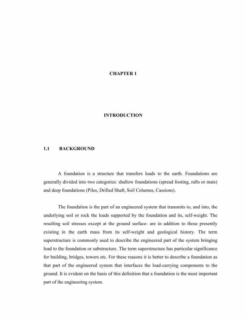
1.1 BACKGROUND
A foundation is a structure that transfers loads to the earth. Foundations are
generally divided into two categories: shallow foundations (spread footing, rafts or mats)
and deep foundations (Piles, Drilled Shaft, Soil Columns, Cassions).
The foundation is the part of an engineered system that transmits to, and into, the
underlying soil or rock the loads supported by the foundation and its, self-weight. The
resulting soil stresses except at the ground surface- are in addition to those presently
existing in the earth mass from its self-weight and geological history. The term
superstructure is commonly used to describe the engineered part of the system bringing
load to the foundation or substructure. The term superstructure has particular significance
for building, bridges, towers etc. For these reasons it is better to describe a foundation as
that part of the engineered system that interfaces the load-carrying components to the
ground. It is evident on the basis of this definition that a foundation is the most important
part of the engineering system.
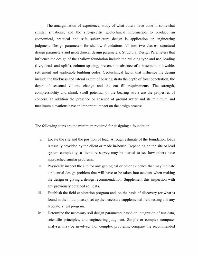
The amalgamation of experience, study of what others have done in somewhat
similar situations, and the site-specific geotechnical information to produce an
economical, practical and safe substructure design is application or engineering
judgment. Design parameters for shallow foundations fall into two classes; structural
design parameters and geotechnical design parameters. Structural Design Parameters that
influence the design of the shallow foundation include the building type and use, loading
(live, dead, and uplift), column spacing, presence or absence of a basement, allowable,
settlement and applicable building codes. Geotechnical factor that influence the design
include the thickness and lateral extent of bearing strata the depth of frost penetration, the
depth of seasonal volume change and the cut fill requirements. The strength,
compressibility and shrink swell potential of the bearing strata are the properties of
concern. In addition the presence or absence of ground water and its minimum and
maximum elevations have an important impact on the design process.
The following steps are the minimum required for designing a foundation:
i. Locate the site and the position of load. A rough estimate of the foundation loads
is usually provided by the client or made in-house. Depending on the site or load
system complexity, a literature survey may be started to see how others have
approached similar problems.
ii. Physically inspect the site for any geological or other evidence that may indicate
a potential design problem that will have to be taken into account when making
the design or giving a design recommendation. Supplement this inspection with
any previously obtained soil data.
iii. Establish the field exploration program and, on the basis of discovery (or what is
found in the initial phase), set up the necessary supplemental field testing and any
laboratory test program.
iv. Determine the necessary soil design parameters based on integration of test data,
scientific principles, and engineering judgment. Simple or complex computer
analyses may be involved. For complex problems, compare the recommended
data with published literature or engage another geotechnical consultant to give
an outside perspective to the results.
v. Design the foundation using the soil parameters from step (iv). The foundation
should be economical and be able to be built by the available construction
personnel. Take into account practical construction tolerances and local
construction practices. Interact closely with all concerned (client, engineers,
architect, contractor) so that the substructure system is not excessively over
designed and risk is kept within acceptable levels. A computer may be used
extensively (or not at all) in this step.
Normally, for building height 2 – 4 storey, the geotechnical engineer not involve
for foundation design. The structural engineer whose design overall the building. For
design the foundation, the structural engineers usually choose piles foundation for more
safety and not complicated especially using structural software design. Drawing
construction, the contractor more prefer shallow the foundation for more economical and
faster in construction. Thus, the characteristic and the strata of the soil at the site must
suitable for shallow foundation. For replacement piles foundation design to raft or mat
foundation design, the geotechnical engineer are challenged to suit this soil condition
suitable or not for raft or mat foundation.
1.2 PROBLEM STATEMENT
Originally foundation design for Project 4 Storey Asrama Kelompok, Yayasan
Terengganu had used piling system. After project awarded to contractor, contractor
propose conversion of foundation system from piling to raft foundation with it reason
will be able to accelerate again building process later apart from cost factor can be saved
to client.
After client consented the proposal, then geotechnical engineer are challenge to
suit the Soil Condition are suitable for use the mat (or raft) foundations.

To make sure the bearing capacity and settlement adequate.
1.3 OBJECTIVE OF STUDY
The objectives of this study are as follows:
i. To evaluate cost implications of the pile foundations and mat or raft foundations.
ii. Analysis numerical modeling (Using PLAXIS) to evaluate the settlement mat or
raft foundation in good agreement with actual performance.
iii. To obtaining adopted soil stiffness in soil condition.
1.4 SCOPE OF STUDY
The scope of the study includes several aspects as follows:
i. Study bearing capacity for raft foundation.
ii. Literature review on previous factor settlement in raft foundation.
iii. Suggestion using raft foundation for certain soil properties.
iv. Calculation for comparison cost estimate between pile foundation and raft
foundation.
CHAPTER 2
LITERATURE REVIEW
2.1 COMPUTATIONAL GEOTECHNICS AND SOIL – FOUNDATION – STRUCTURE INTERACTION
2.1.1 Introduction
The purpose of the geotechnical software is to provide engineers with the
practical application of Seismic Soil – Foundation – Structure Interaction involving
finite element method (FEM) and other techniques. This provides the practical aspect of
finite element method (FEM) for shallow foundation, deep foundation, retaining
structures, deep execution and tunnel.
Finite element method is a computational procedure that may be used to obtain
approximate solution to mathematical problem that arise in a variety of area of
engineering, one of the finite element packages is PLAXIS software that has been
developed specifically for the analysis of deformation and stability in geotechnical
engineering project.

2.1.2 PLAXIS
PLAXIS is finite element package specially intended for the analysis of
deformation and stability in geotechnical engineering projects. Geotechnical applications
required advance constitutive model for the simulation of the non-linear and time-
dependent behavior of soil. In addition, since soil is multi-phase material, special
procedures are required to deal with hydrostatic and non-hydrostatic pore pressure in the
soil. Although the modeling of the soil itself is an important issue, many geotechnical
engineering projects involve the modeling of structures and interaction between the
structures and the soil. PLAXIS is equipped with special features to deal with numerous
aspects of complex geotechnical structures. PLAXIS enables to model interaction
between structures and the soil.
2.2 ANALYSIS AND DESIGN OF SHALLOW FOUNDATION
By far the most common structural foundation in today’s construction industry is
the shallow foundation. Other types of foundation, such as piles, piers, caissons, and
similar deep foundations are used primarily for major structures, not for ordinary building
that constitute the overwhelming majority of all construction.
2.2.1 Advantages of Using Shallow
1. Cost (affordable)
2. Construction Procedure (simple)
3. Materials ( mostly concrete)
4. Labor (does not need expertise)
2.2.2 Disadvantages of Using Shallow
1. Settlement
2. Limit Capacity * Soil * Structure
3. Irregular ground surface (slope, retaining wall)
4. Foundation subjected to pullout, torsion, moment.
2.2.3 Combined Footings
Types of Combined Footing:
1. Rectangular Combined Footing
2. Trapezoidal Combined Footing
3. Cantilever Footing
4. Mat or Raft Foundation

2.2.4 Types of Mat Foundation (or Raft) Foundations
Mat (or raft) foundation is one type of shallow foundations. Types of Mat (or Raft) Foundation:
1. Flat plate.
- The mat is of uniform thickness.
2. Flat plate thickened under columns
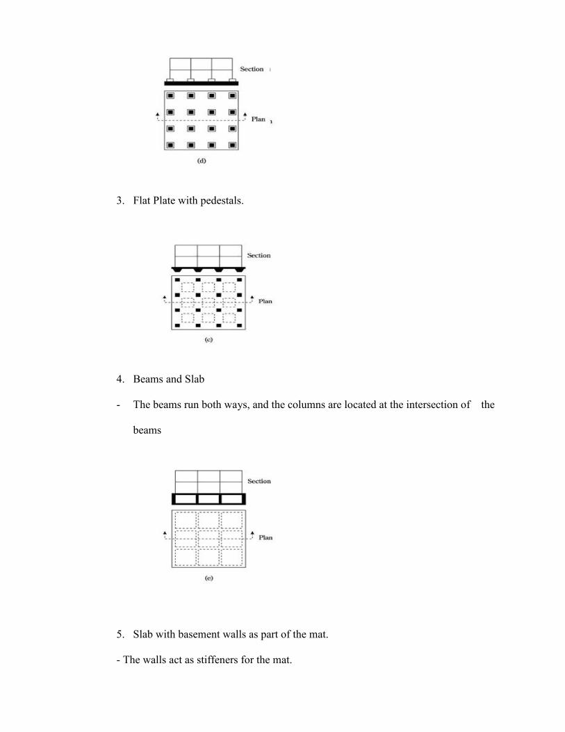
3. Flat Plate with pedestals.
4. Beams and Slab
- The beams run both ways, and the columns are located at the intersection of the
beams
5. Slab with basement walls as part of the mat.
- The walls act as stiffeners for the mat.

2.2.5 To Design a Mat or Raft Foundation:
1. Determine the bearing capacity of the foundation
2. Determine the settlement of the foundation.
3. Determine the differential settlement
4. Determine the stress distribution beneath the foundation
5. Design the structural components of the mat foundation using the stress
distribution obtained from (4).
From Step (4)
a) The mat foundation is assumed to be a rigid foundation
b) The mat foundation is assumed to be a Flexible Foundation; here used Beam on
Elastic
Factor of Safety:
For sand and clay F.S. = 3
In most of the case FS > 1.75 to 2
qall = qu FS
2.3 BEARING CAPACITY AND STABILITY OF MAT OR RAFT
FOUNDATIONS
2.3.1 Introduction
The ability of a soil to support a load from a structural foundation without failing
in shear is known as its bearing capacity.
The stability of foundation depends on:
1. The bearing capacity of the soil beneath the foundation.
2. The settlement of the soil beneath the foundation.
There are, therefore, two independent stability conditions to be fulfilled since the
shearing resistance of the soil provides the bearing capacity and the consolidation
properties determine the settlement.
Because of their large width, mat foundations on sands and gravels do not have
bearing capacity problems. However, bearing capacity might be important in silts and
clays, especially if undrained conditions prevail. The Fargo Grain Silo failure described
in Chapter 6 (Second Edition, Foundation Design Principles and Practices, Donald P.
Coduto, (2001) is a notable example of bearing capacity failure in saturated clay.
We can evaluate bearing capacity using the analysis techniques described in
Chapter 6 (Second Edition, Foundation Design Principles and Practices, Donald P.
Coduto, (2001). It is good practice to design the mat so the bearing pressure at all point is
less than the allowable bearing capacity.

2.3.2 Major Points for Bearing Capacity of Raft or Mat Foundations
1. Mat foundation are essentially large spread footings that usually encompass the
entire footprint of a structure. They are often an appropriate choice for structures
that are too heavy for spread footings.
2. The analysis and design of mats must include an evaluation of the flexural stresses
and must provide sufficient flexural strength to resist these stresses.
3. The oldest and simplest method of analyzing mat is the rigid method. It assumes
that the mat is much more rigid than the underlying soil, which means the
magnitude and distribution of bearing pressure is easy to determine. This means the
shears, moment, and deformations in the mat are easily determined. However, this
method is not an accurate representation because the assumption of rigidity is not
correct.
4. Nonrigid analyses are superior because they consider the flexural deflections in the
mat and the corresponding redistribution of the soil bearing pressure.
5. Nonrigid methods must include a definition of soil-structure interaction. This is
usually done using a “ bed of spring” analogy, with each spring having a linear
force-displacement function as defined by the coefficient of subgrade reaction, ks.
6. The simplest and oldest nonrigid method is the Winkler method, which uses
independent springs, all of which have same ks. This method is an improvement
over rigid analyses, but still does not accurately model soil – structure interaction,
primarily because it does not consider coupling effects.
7. The coupled method is an extension of the Winkler method that considers coupling
between the springs.
8. The pseudo-coupled method uses independent spring, but adjusts the ks values to
implicitly account for coupling effects.
9. The multiple parameter and finite element method are more advance ways of
describing soil-structure interaction.
10. The coefficient of subgrade reaction is difficult to determine. Fortunately, the mat
design is often not overly sensitive to global changes in ks. Parametric studies are
often appropriate.
11. If the Winkles method is used to describe soil-structure interaction, and geometry is
not too complex, the structural analysis may be performed closed-form solutions.
However, these methods are generally considered obstacle.
12. Most structural analyses are performed using numerical methods, especially for nite
element method. This method uses finite elements to model the mat and principle, it
also could used the multiple parameter model.
13. A design could be based entirely on a three-dimensional finite element analysis
includes the soil, mat, and superstructure. However, such analyses are beyond rent
practices, mostly because they are difficult to set up and require especially powerful
computers.
14. The total settlement is best determined using the method described in Chapter 6
(Second Edition, Foundation Design Principles and Practices, Donald P. Coduto,
(2001). Do not use the coefficient of subgrade reaction to determine total
settlement.
15. Bearing capacity is not a problem with sands and gravely, but can be important a
silts and clays. It should be checked using the methods describe in Chapter
6(Second Edition, Foundation Design Principles and Practices, Donald P. Coduto,
(2001).
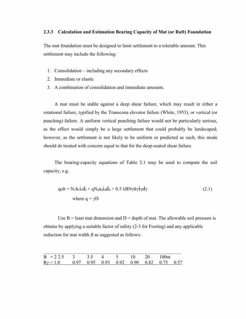
2.3.3 Calculation and Estimation Bearing Capacity of Mat (or Raft) Foundation
The mat foundation must be designed to limit settlement to a tolerable amount. This
settlement may include the following:
1. Consolidation – including any secondary effects
2. Immediate or elastic
3. A combination of consolidation and immediate amounts.
A mat must be stable against a deep shear failure, which may result in either a
rotational failure, typified by the Transcona elevator failure (White, 1953), or vertical (or
punching) failure. A uniform vertical punching failure would not be particularly serious,
as the effect would simply be a large settlement that could probably be landscaped;
however, as the settlement is not likely to be uniform or predicted as such, this mode
should de treated with concern equal to that for the deep-seated shear failure.
The bearing-capacity equations of Table 2.1 may be used to compute the soil
capacity, e.g.
qult = Ncscicdc + qNqsqiqdq + 0.5 λBNγsγiγdγ (2.1)
where q = γD
Use B = least mat dimension and D = depth of mat. The allowable soil pressure is
obtains by applying a suitable factor of safety (2-3 for Footing) and any applicable
reduction for mat width B as suggested as follows:
_________________________________________________________ B = 2 2.5 3 3.5 4 5 10 20 100m Rγ = 1.0 0.97 0.95 0.93 0.92 0.90 0.82 0.75 0.57
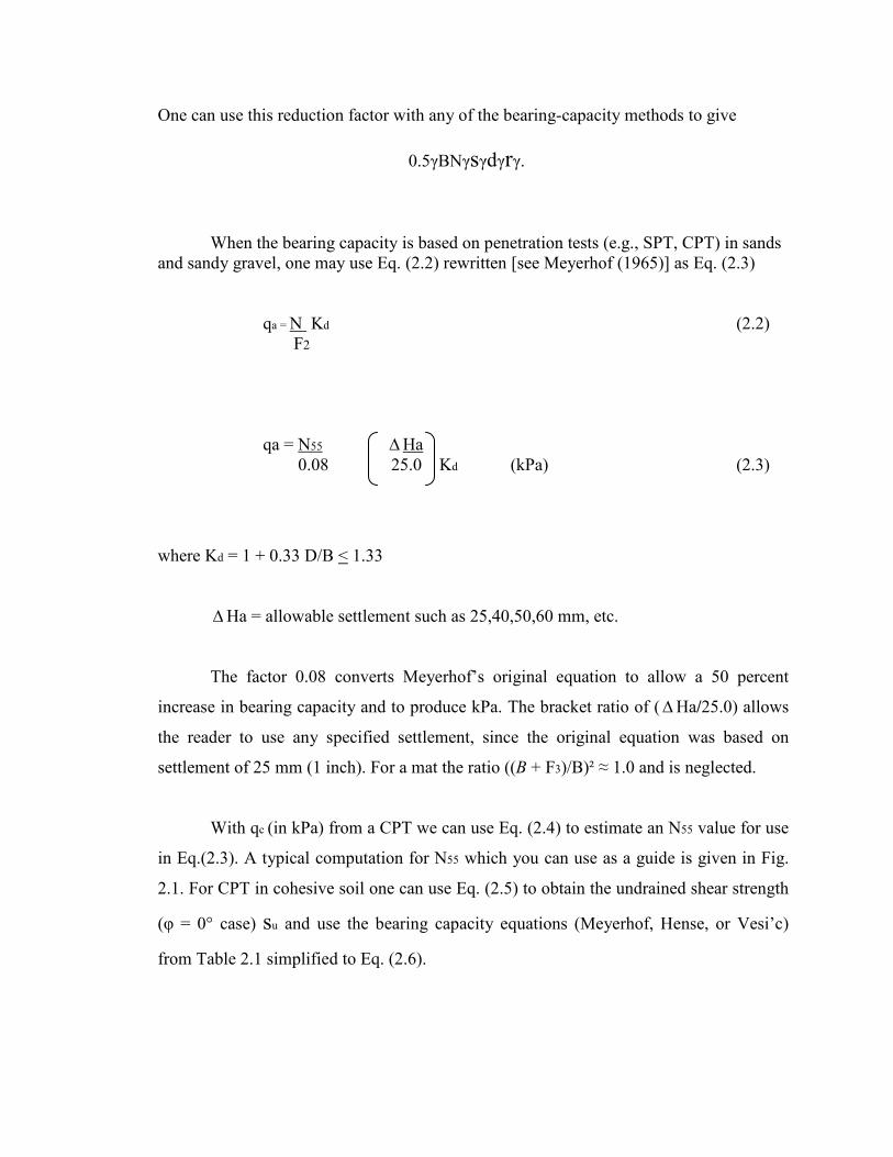
One can use this reduction factor with any of the bearing-capacity methods to give
0.5γBNγsγdγrγ.
When the bearing capacity is based on penetration tests (e.g., SPT, CPT) in sands and sandy gravel, one may use Eq. (2.2) rewritten [see Meyerhof (1965)] as Eq. (2.3)
qa = N Kd (2.2) F2 qa = N55 ∆Ha
0.08 25.0 Kd (kPa) (2.3)
where Kd = 1 + 0.33 D/B < 1.33
∆Ha = allowable settlement such as 25,40,50,60 mm, etc.
The factor 0.08 converts Meyerhof’s original equation to allow a 50 percent
increase in bearing capacity and to produce kPa. The bracket ratio of (∆Ha/25.0) allows
the reader to use any specified settlement, since the original equation was based on
settlement of 25 mm (1 inch). For a mat the ratio ((B + F3)/B)² ≈ 1.0 and is neglected.
With qc (in kPa) from a CPT we can use Eq. (2.4) to estimate an N55 value for use
in Eq.(2.3). A typical computation for N55 which you can use as a guide is given in Fig.
2.1. For CPT in cohesive soil one can use Eq. (2.5) to obtain the undrained shear strength
(φ = 0° case) su and use the bearing capacity equations (Meyerhof, Hense, or Vesi’c)
from Table 2.1 simplified to Eq. (2.6).
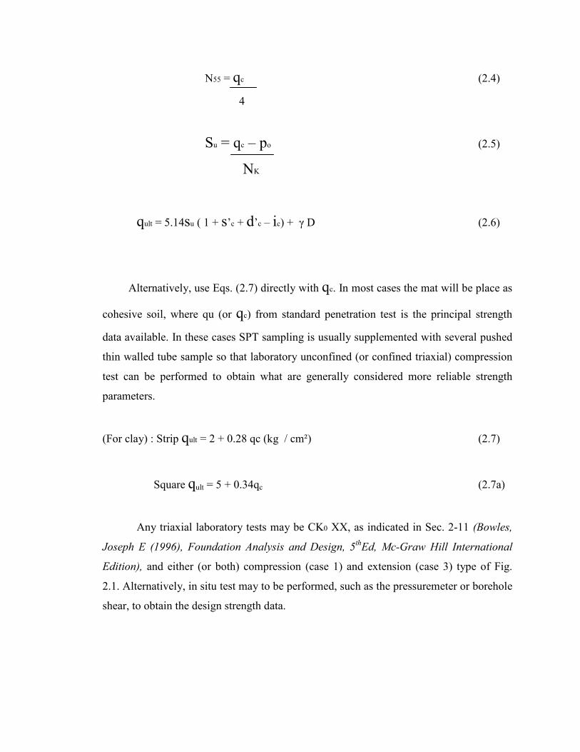
N55 = qc (2.4)
4
Su = qc – po (2.5)
NK
qult = 5.14su ( 1 + s’c + d’c – ic) + γ D (2.6)
Alternatively, use Eqs. (2.7) directly with qc. In most cases the mat will be place as
cohesive soil, where qu (or qc) from standard penetration test is the principal strength
data available. In these cases SPT sampling is usually supplemented with several pushed
thin walled tube sample so that laboratory unconfined (or confined triaxial) compression
test can be performed to obtain what are generally considered more reliable strength
parameters.
(For clay) : Strip qult = 2 + 0.28 qc (kg / cm²) (2.7)
Square qult = 5 + 0.34qc (2.7a)
Any triaxial laboratory tests may be CK0 XX, as indicated in Sec. 2-11 (Bowles,
Joseph E (1996), Foundation Analysis and Design, 5thEd, Mc-Graw Hill International
Edition), and either (or both) compression (case 1) and extension (case 3) type of Fig.
2.1. Alternatively, in situ test may to be performed, such as the pressuremeter or borehole
shear, to obtain the design strength data.
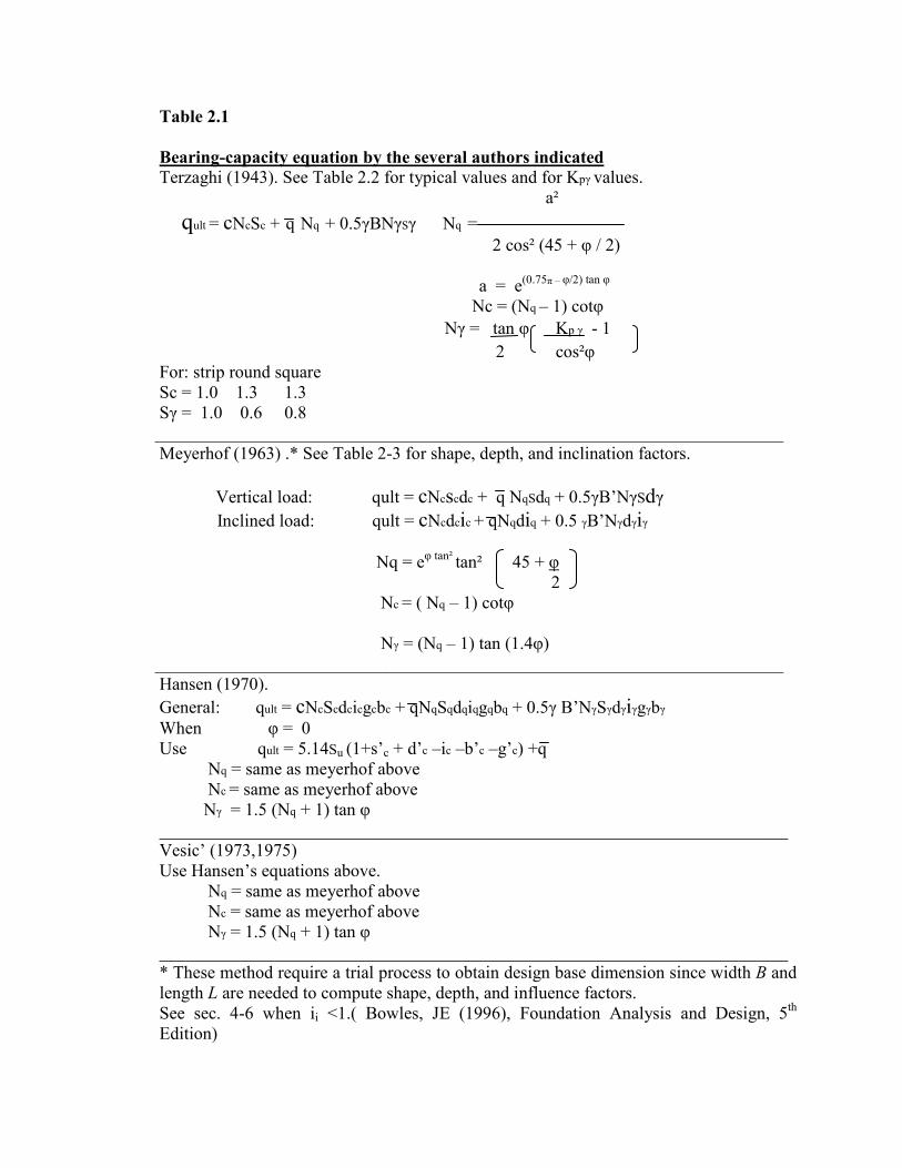
Table 2.1 Bearing-capacity equation by the several authors indicated Terzaghi (1943). See Table 2.2 for typical values and for Kpγ values.
a²
qult = cNcSc + q Nq + 0.5γBNγSγ Nq = 2 cos² (45 + φ / 2)
a = e(0.75π – φ/2) tan φ Nc = (Nq – 1) cotφ
Nγ = tan φ Kp γ - 1 2 cos²φ
For: strip round square Sc = 1.0 1.3 1.3 Sγ = 1.0 0.6 0.8
_______________________________________________________________________ Meyerhof (1963) .* See Table 2-3 for shape, depth, and inclination factors.
Vertical load: qult = cNcscdc + q NqSdq + 0.5γB’NγSdγ Inclined load: qult = cNcdcic + qNqdiq + 0.5 γB’Nγdγiγ Nq = eφ tan² tan² 45 + φ 2 Nc = ( Nq – 1) cotφ Nγ = (Nq – 1) tan (1.4φ) _______________________________________________________________________
Hansen (1970). General: qult = cNcScdcicgcbc + qNqSqdqiqgqbq + 0.5γ B’NγSγdγiγgγbγ When φ = 0 Use qult = 5.14Su (1+s’c + d’c –ic –b’c –g’c) +q
Nq = same as meyerhof above Nc = same as meyerhof above Nγ = 1.5 (Nq + 1) tan φ _______________________________________________________________________
Vesic’ (1973,1975) Use Hansen’s equations above.
Nq = same as meyerhof above Nc = same as meyerhof above Nγ = 1.5 (Nq + 1) tan φ _______________________________________________________________________
* These method require a trial process to obtain design base dimension since width B and length L are needed to compute shape, depth, and influence factors. See sec. 4-6 when ii <1.( Bowles, JE (1996), Foundation Analysis and Design, 5th Edition)

Table 2.2
Bearing –capacity factor for the Terzaghi equation Values of Nγ for φ of 0,3, and 48° are original Terzaghi values and used to back-compute Kpγ
_____________________________________________________ φ, deg Nc Nq Nγ Kpγ________ 0 5.7* 1.0 0.0 10.8 5 7.3 1.6 0.5 12.2 10 9.6 2.7 1.2 14.7 15 12.9 4.4 2.5 18.6 20 17.7 7.4 5.0 25.0 25 25.1 12.7 9.7 35.0 30 37.2 22.5 19.7 52.0 34 52.6 36.5 36.0 35 57.8 41.4 42.4 82.0 40 95.7 81.3 100.4 141.0 45 172.3 173.3 297.5 298.0 48 258.3 287.9 780.1 50 347.5 415.1 1153.2 800.0___ *Nc = 1.5π + 1
Table 2.3
Shape, depth, and inclination factors for the Meyerhof bearing-capacity equation of the Table 2.1 ______________________________________________________
Factors Value For_____ Shape Sc = 1 + 0.2 Kp B Any φ L Sq = Sγ = 1 + 0.1 Kp B φ > 10 L Sq = Sγ = 1 φ = 0
Depth dc = 1 + 0.2 Kp D Any φ B
dc =dγ = 1 + 0.1 Kp D φ > 10 B dq = dγ = 1 φ = 0 Inclination: ic = iq = 1-θ° ² Any φ R φ V 90° v iγ = 1 - θ° ² φ >0 θ φ° H iγ = 0 for θ > 0 φ = 0 _______________________________________________________
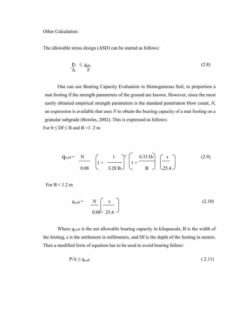
Other Calculation:
The allowable stress design (ASD) can be started as follows:
P ≤ qult (2.8) A F
One can use Bearing Capacity Evaluation in Homogeneous Soil, to proportion a
mat footing if the strength parameters of the ground are known. However, since the most
easily obtained empirical strength parameters is the standard penetration blow count, N,
an expression is available that uses N to obtain the bearing capacity of a mat footing on a
granular subgrade (Bowles, 2002). This is expressed as follows:
For 0 ≤ Df ≤ B and B >1 .2 m
qn,all = N 1 ² 0.33 Df s (2.9) 1 + 1 + 0.08 3.28 B B 25.4
For B < 1.2 m qn,all = N s (2.10) 0.08 25.4
Where qn,all is the net allowable bearing capacity in kilopascals, B is the width of
the footing, s is the settlement in millimeters, and Df is the depth of the footing in meters.
Then a modified form of equation has to be used to avoid bearing failure:
P/A ≤ qn,all ( 2.11)

It is again seen in Equation (2.10) that the use of a safety factor is precluded by employing an allowable bearing capacity. The net ultimate bearing capacity for Cohessive Soil.
qnet (u) = 5.14 Cu 1 + 0.195 B 1 + 0.4Dƒ (2.12) L B
qall (net) = qnet (u) (2.13) FS
2.4 SETTLEMENT OF MAT (OR RAFT) FOUNDATION
2.4.1 Introduction
The evaluation of bearing capacity of soil and use of factor of safety implies a
consideration of how much settlement can be tolerated by the structure. While many
structures can tolerate substantial total settlement, differential settlement is more
troublesome because it causes distortion and damages to the structure.
The amount of settlement that can be tolerated by a structure depends on the
function, the type and the material that can make up the structure. For most facilities on
sand, total settlement is limited to 50 mm. for structure on clay, a total settlement of 75
mm is acceptable because the foundation on clay settle much more slowly than the
foundation on sand. Differential settlement should not usually exceed 12 mm while the
angular distortion is limited to 1/500 of the distance between two columns. Differential
settlement between one part of the structure and another is greater significance because it
can cause a detrimental effect to the superstructure such as cracks.
The settlement of a shallow foundation is categorized as immediate settlement
and consolidation settlement.
The immediate settlement takes place as soon as load is applied. This settlement is
caused by the elastic deformation of the soil mass or by the rearrangement of clay
particles due to compaction. The settlement analysis is required for all coarse gained soil
with large coefficient of permeability and all fined grained soil including silts clay
existed in unsaturated conditions.
The consolidation settlement is pore water pressure dissipation from soil. The
time needed to complete the process depends on the permeability of soil. In granular soil
or sand, water dissipates very quickly from void because of its high permeability,
therefore primary consolidation may be insignificant and could be neglected. On the
other hand, consolidation process can take several years to complete and lead to
significant settlement for footing on fined grained soil especially clay. Consolidation
settlement analysis should be used for all fined grained soil in saturated condition.
2.4.2 Compressibility and Settlement
Soils, like any other material, deform under loads. Hence, even if the condition of
structural integrity or bearing capacity of a foundation is satisfied, the ground supporting
the structure can undergo compression, leading to structural settlement. In most dry soils,
this settlement will cease almost immediately after the particles readjust in order to attain
an equilibrium with the structural load. For convenience, this immediate settlement is
evaluated using the theory of elasticity although it is very often nonelastic in nature.
2.4.2.1 Estimation of Immediate Settlement in Soils
The most commonly adopted analytical methods for immediate settlement
evaluation in soils are based on the elastic theory. However, one must realize that reliable
estimates of elastic moduli and Poisson ratio values for soil are not easily
obtained. This is mainly because of the sampling difficulty and, particularly, the
dependency of the elastic modulus on the stress state. On the other hand, reliable field
methods for obtaining elastic moduli are also scarce. Very often, settlement of footings
founded on granular soils or unsaturated clays is determined on the basis of plate load
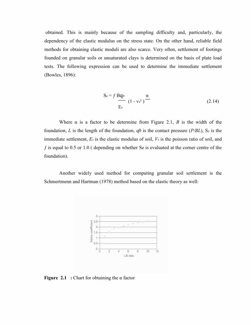
tests. The following expression can be used to determine the immediate settlement
(Bowles, 1896):
Se = ƒ Bq0 α
(1 - vs² ) (2.14) Es
Where α is a factor to be determine from Figure 2.1, B is the width of the
foundation, L is the length of the foundation, q0 is the contact pressure (P/BL), Se is the
immediate settlement, Es is the elastic modulus of soil, Vs is the poisson ratio of soil, and
ƒ is equal to 0.5 or 1.0 ( depending on whether Se is evaluated at the corner centre of the
foundation).
Another widely used method for computing granular soil settlement is the
Schmertmenn and Hartman (1978) method based on the elastic theory as well:
Figure 2.1 : Chart for obtaining the α factor
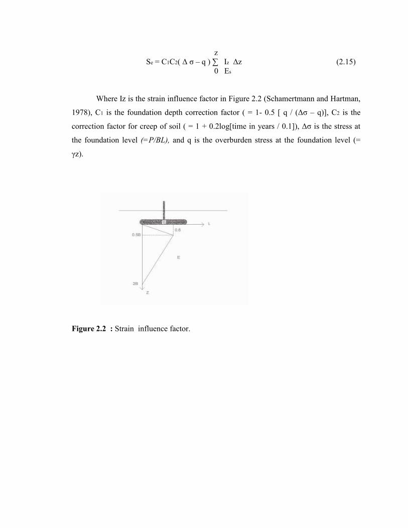
z Se = C1C2( ∆ σ – q ) ∑ Iz ∆z (2.15) 0 Es
Where Iz is the strain influence factor in Figure 2.2 (Schamertmann and Hartman,
1978), C1 is the foundation depth correction factor ( = 1- 0.5 [ q / (∆σ – q)], C2 is the
correction factor for creep of soil ( = 1 + 0.2log[time in years / 0.1]), ∆σ is the stress at
the foundation level (=P/BL), and q is the overburden stress at the foundation level (=
γz).
Figure 2.2 : Strain influence factor.

Table 2.4 : Poisson Ratio (µ) for Geomaterials ( Manjriker Gunarate (2006). The foundation Engineering Hand Book)
__________________________________________________________ Type of Soil µ _______________________________________________________________________________________ Clay, saturated 0.4-0.5 Clay, Unsaturated 0.1-0.3 Sandy clay 0.2-0.3 Silt 0.3-0.35 Sand, gravelly sand -0.1 to 1.00 Commonly used 0.3-0.4 Rock 0.1-0.4 (depends somewhat on type of rock) Loess 0.1-0.3 Ice 0.36 Concrete 0.15 Steel 0.33 ________________________________________________________________________________________ Sources: From Bowles, J.E., 2002, Foundation Analysis and Design, McGraw-Hill, NewbYork. With
Permission.
The elastic properties needed to manipulate the above expression are provided in
Tables 2.4 ( Bowles, 1995) and Table 2.5, where the author, based on his experience, has
extracted approximate values from Bowles (1995) for most common soil types.
Table 2.5 : Approximate Elastic Moduli of Geomateials ( Manjriker Gunarate (2006). The foundation Engineering Hand Book)
Elastic Modulus Soil Type (MPa)
Soft clay 2-25 Medium clay 15-50 Stiff clay 50-100 Loose sand 10-20 Medium dense sand 20-50 Dense sand 50-80 Loose gravel (sandy) 50-150 Dense gravel (sandy) 100-200 Silt 2-20
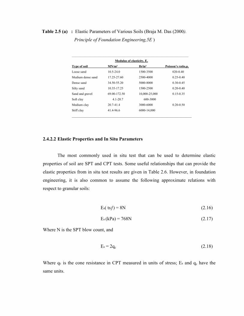
Table 2.5 (a) : Elastic Parameters of Various Soils (Braja M. Das (2000).
Principle of Foundation Engineering,5E )
_________________________________________________________________________
Modulus of elasticity, Es
Type of soil MN/m² Ib/in² Poisson’s ratio,µs
Loose sand 10.5-24.0 1500-3500 020-0.40
Medium dense sand 17.25-27.60 2500-4000 0.25-0.40
Dense sand 34.50-55.20 5000-8000 0.30-0.45
Silty sand 10.35-17.25 1500-2500 0.20-0.40
Sand and gravel 69.00-172.50 10,000-25,000 0.15-0.35
Soft clay 4.1-20.7 600-3000
Medium clay 20.7-41.4 3000-6000 0.20-0.50
Stiff clay 41.4-96.6 6000-14,000
___________________________________________________________________________
2.4.2.2 Elastic Properties and In Situ Parameters
The most commonly used in situ test that can be used to determine elastic
properties of soil are SPT and CPT tests. Some useful relationships that can provide the
elastic properties from in situ test results are given in Table 2.6. However, in foundation
engineering, it is also common to assume the following approximate relations with
respect to granular soils:
Es( tsƒ) = 8N (2.16) Es (kPa) = 768N (2.17)
Where N is the SPT blow count, and Es = 2qc (2.18)
Where qc is the cone resistance in CPT measured in units of stress; Es and qc have the
same units.
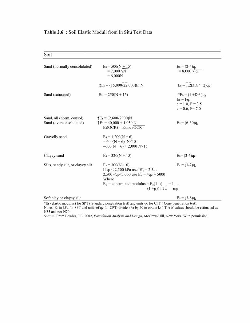
Table 2.6 : Soil Elastic Moduli from In Situ Test Data ________________________________________________________________________ Soil Sand (normally consolidated) Es = 500(N + 15) Es = (2-4)qu = 7,000 √N = 8,000 √ qc = 6,000N _ _ _ _ ‡Es = (15,000-22,000)In N Es = 1.2(3Dr² +2)qc
Sand (saturated) Es = 250(N + 15) *Es = (1 +Dr² )qc Es = Fqc e = 1.0, F = 3.5 e = 0.6, F= 7.0 Sand, all (norm. consol) ¶Es = (2,600-2900)N Sand (overconsolidated) †Es = 40,000 + 1,050 N Es = (6-30)qc Es(OCR) ≈ Es,nc√OCR Gravelly sand Es = 1,200(N + 6) = 600(N + 6) N<15 =600(N + 6) + 2,000 N>15 Clayey sand Es = 320(N + 15) Es= (3-6)qc
Silts, sandy silt, or clayey silt Es = 300(N + 6) Es = (1-2)qc
If qc < 2,500 kPa use sErs = 2.5qc
2,500 <qc<5,000 use Ets = 4qc + 5000
Where Et
s = constrained modulus = E3(1-µ) = 1 (1 +µ)(1-2µ mµ
Soft clay or clayey silt Es = (3-8)qc *Es (elastic modulus) for SPT ( Standard penetration test) and units qc for CPT ( Cone penetration test). Notes: Es in kPa for SPT and units of qc for CPT; divide kPa by 50 to obtain ksf. The N values should be estimated as N55 and not N70.
Source: From Bowles, J.E.,2002, Foundation Analysis and Design, McGraw-Hill, New York. With permission
2.4.5 Settlement Analysis
Methodologies used for computation of ground settlement under building
foundations have been discussed in detail in 2.4.2. Therefore, in this section, a number of
techniques that are commonly employed to evaluate the ground stress increase due to
footings will be reviewed. Then a number of examples will be provided to illustrate the
application of the above techniques.
2.4.5.1 Stress Distribution in Subsurface Soils due to Foundation Loading
(i) Analytical Methods
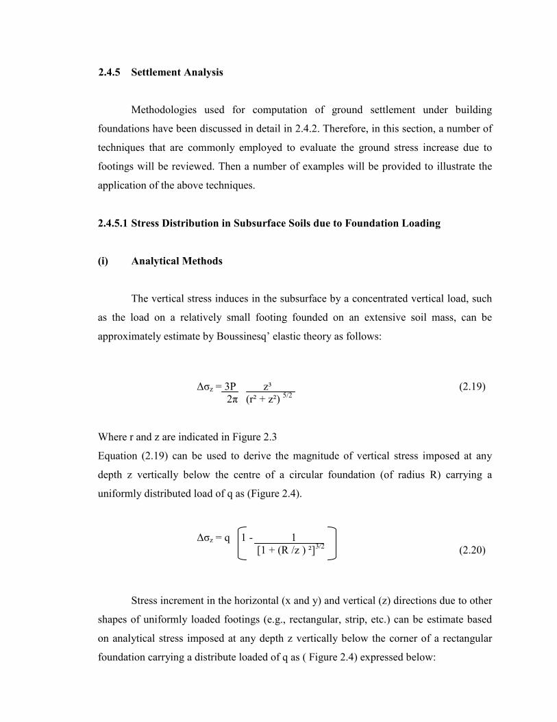
The vertical stress induces in the subsurface by a concentrated vertical load, such
as the load on a relatively small footing founded on an extensive soil mass, can be
approximately estimate by Boussinesq’ elastic theory as follows:
∆σz = 3P z³ (2.19)
2π (r² + z²) 5/2 Where r and z are indicated in Figure 2.3
Equation (2.19) can be used to derive the magnitude of vertical stress imposed at any
depth z vertically below the centre of a circular foundation (of radius R) carrying a
uniformly distributed load of q as (Figure 2.4).
∆σz = q 1 - 1 [1 + (R /z ) ²]3/2 (2.20)
Stress increment in the horizontal (x and y) and vertical (z) directions due to other
shapes of uniformly loaded footings (e.g., rectangular, strip, etc.) can be estimate based
on analytical stress imposed at any depth z vertically below the corner of a rectangular
foundation carrying a distribute loaded of q as ( Figure 2.4) expressed below:

∆σz = qK(m, n) (2.21)
Where m = length / width of the foundation and n = z / foundation width. Values
of K(m, n) are tabulate in Table 3.8. Equation (2.21) can also be applied to determine the
stress increase at any point under the loaded area using partitions of the loaded area in
which the corner coincide in plan with the point of interest.
(ii) Approximate Stress Distribution Method
At it is more convenient to estimate the subsurface stress increments due to
footings using approximate distributions. A commonly used distribution is the 2:1
distribution shown in Figure 2.5, it can be seen that the stress increment caused by
uniformly loaded rectangular footing ( B x L ) at a depth of z is
∆σz = q BL ( 2.22) (B + z ) ( L + z )
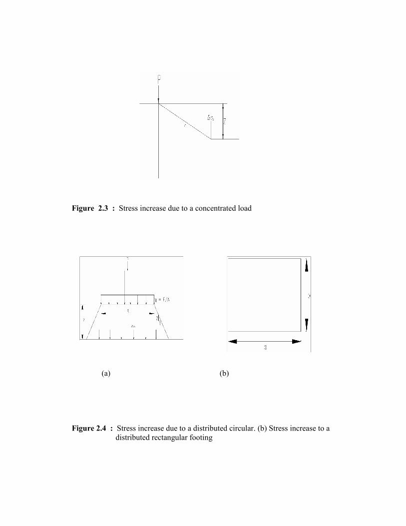
Figure 2.3 : Stress increase due to a concentrated load
(a) (b)
Figure 2.4 : Stress increase due to a distributed circular. (b) Stress increase to a distributed rectangular footing

Figure 2.5 : Approximate estimation of subsurface vertical stress increment.
2.4.6 Calculation and Estimation Settlement of Mat (or Raft) Foundations
The settlement of mat footings can also be estimated using the methods that were outline
in (2.4.5 ) and, assuming that they impart stresses on the ground in a manner similar to
that of spread footings. An example of the estimation immediate settlement under a mat
footing is provided below ( Figure 2.6)
Figure 2.6 : Immediate settlement computation for mat footings

2.4.6.1 Immediate Settlement
The following expression ( Timoshenko nad Goodier, 1951) based on the theory
of elasticity can be used to estimate the corner settlement of rectangular footing with
dimension of L’ and B’,
Si = qB’ 1 - v²s I1 + 1 – 2 vs 12 1F (2.23)
Es 1 - vs
Where q is the contact stress, B’ is the least dimension of the footing, vs is the
poisson ratio of the soil, and Es is the elastic modulus of the soil. Factor I1, 12, and IF are
obtained from Table 2.7 and Figure 2.7. respectively, in terms of the ratios N = H / B’ ( H
= layer thickness), M = L’ / B’( L’ = other dimension of the footing), and D / B.
The same expression (Equation 2.23) can be used to estimate the settlement of
the footing at any point other than the corner by approximate partitioning of the footing
as illustrated in this example. It must be noted that even if the footing is considered as a
combination of several partitions ( B’ and L’), for determining the settlement of an
intermediate (noncorner) location, the depth factor, IF, is applied for the entire footing
based on the ratio D / B.
Figure 2.7 : Plot of the depth influence factor IF for Equation (2.23)
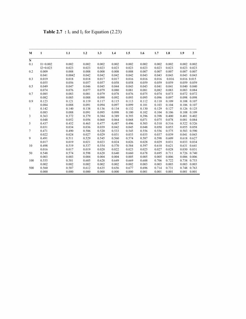
Table 2.7 : I1 and I2 for Equation (2.23)
________________________________________________________________________________________________________
M 1 1.1 1.2 1.3 1.4 1.5 1.6 1.7 1.8 1.9 2 ________________________________________________________________________________________________________ N 0.1 I1=0.002 0.002 0.002 0.002 0.002 0.002 0.002 0.002 0.002 0.002 0.002 I2=0.023 0.023 0.023 0.023 0.023 0.023 0.023 0.023 0.023 0.023 0.023 0.2 0.009 0.008 0.008 0.008 0.008 0.008 0.007 0.007 0.007 0.007 0.007 0.041 0.0042 0.042 0.042 0.042 0.042 0.043 0.043 0.043 0.043 0.043 0.3 0.019 0.018 0.018 0.017 0.017 0.016 0.016 0.016 0.016 0.016 0.015 0.055 0.056 0.057 0.057 0.058 0.058 0.059 0.059 0.059 0.059 0.059 0.5 0.049 0.047 0.046 0.045 0.044 0.043 0.043 0.041 0.041 0.040 0.040 0.074 0.076 0.077 0.079 0.080 0.081 0.081 0,082 0.083 0.083 0.084 0.7 0.085 0.083 0.081 0.079 0.078 0.076 0.075 0.074 0.073 0.072 0.072 0.082 0.085 0.088 0.090 0.092 0.093 0.095 0.096 0.097 0.098 0.098 0.9 0.123 0.121 0.119 0.117 0.115 0.113 0.112 0.110 0.109 0.108 0.107 0.084 0.088 0.091 0.094 0.097 0.099 0.101 0.103 0.104 0.106 0.107 1 0.142 0.140 0.138 0.136 0.134 0.132 0.130 0.129 0.127 0.126 0.125 0.083 0.088 0.091 0.095 0.098 0.100 0.102 0.104 0.106 0.108 0.109 3 0.363 0.372 0.379 0.384 0.389 0.393 0,396 0.398 0.400 0.401 0.402 0.048 0.052 0.056 0.060 0.064 0.068 0,071 0.075 0.078 0.081 0.084 5 0.437 0.452 0.465 0.477 0,487 0.496 0.503 0.510 0.516 0.522 0.526 0.031 0.034 0.036 0.039 0.042 0.045 0.048 0.050 0.053 0.055 0.058 7 0.471 0.490 0.506 0.520 0.533 0.545 0.556 0.556 0.575 0.583 0.590 0.022 0.024 0.027 0.029 0.031 0.033 0.035 0.037 0.039 0.041 0.043 9 0.491 0.511 0.529 0.545 0.560 0.574 0.587 0.598 0.609 0.618 0.627 0.017 0.019 0.021 0.023 0.024 0.026 0.028 0.029 0.031 0.033 0.034 10 0.498 0.519 0.537 0.554 0.570 0.584 0.597 0.610 0.621 0.631 0.641 0.016 0.017 0.019 0.020 0.022 0.023 0.025 0.027 0.028 0.030 0.031 50 0.548 0.574 0.598 0.620 0.640 0.660 0.678 0.695 0.711 0.726 0.740 0.003 0.003 0.004 0.004 0.004 0.005 0.005 0.005 0.006 0.006 0.006 100 0.555 0.581 0.605 0.628 0.649 0.669 0.688 0.706 0.722 0.738 0.753 0.002 0.002 0.002 0.002 0.002 0.002 0.003 0.003 0.003 0.003 0.003 500 0.560 0.587 0.612 0.635 0.656 0.677 0.696 0.714 0.731 0.748 0.763 0.000 0.000 0.000 0.000 0.000 0.000 0.001 0.001 0.001 0.001 0.001

Table 2.7 : I1 and I2 for Equation (2.23) – Continue
_________________________________________________________________________________________________________________
M 2.5 3.5 5 6 7 8 9 10 15 25 50 100 _________________________________________________________________________________________________________________ N 0.1.1 I1=0.002 0.002 0.002 0.002 0.002 0.002 0.002 0.002 0.002 0.002 0.002 0.002 I2=0.023 0.023 0.023 0.023 0.023 0.023 0.023 0.023 0.023 0.023 0.023 0.023 0.2 0.007 0.006 0.006 0.006 0.006 0.006 0.006 0.006 0.006 0.006 0.007 0.006 0.043 0.043 0.044 0.044 0.044 0.044 0.044 0.044 0.044 0.044 0.044 0.044 0.3 0.015 0.014 0.014 0.014 0.014 0.014 0.014 0.014 0.014 0.014 0.014 0.014 0.060 0.061 0.061 0.061 0.061 0.061 0.061 0.061 0.061 0.061 0.061 0.061 0.5 0.038 0.037 0.036 0.036 0.036 0.036 0.036 0.036 0.036 0.036 0.036 0.036 0.085 0.087 0.087 0.088 0.088 0.088 0.088 0.088 0.088 0.088 0.088 0.088 0.7 0.069 0.066 0.065 0.065 0.064 0.064 0.064 0.064 0.064 0.064 0.063 0.063 0.101 0.104 0.105 0.106 0.106 0.106 0.106 0.107 0.107 0.107 0.107 0.107 0.9 0.103 0.099 0.097 0.096 0.096 0.095 0.095 0.095 0.095 0.095 0.094 0.094 0.111 0.115 0.118 0.118 0.119 0.119 0.119 0.119 0.120 0.120 0.120 0.120 1 0.121 0.116 0.113 0.112 0.112 0.112 0.111 0.111 0.111 0.110 0.110 0.110 0.114 0.119 0.122 0.123 0.123 0.124 0.124 0.124 0.125 0.125 0.125 0.125 3 0.402 0.396 0.386 0.382 0.378 0.376 0.374 0.373 0.370 0.368 0.367 0.367 0.097 0.116 0.131 0.137 0.141 0.144 0.145 0.147 0.151 0.152 0.153 0.154 5 0.543 0.554 0.552 0.548 0.543 0.540 0.536 0.534 0.526 0.522 0.519 0.519 0.070 0.090 0.111 0.120 0.128 0.133 0.137 0.140 0.149 0.154 0.156 0.157 7 0.618 0.646 0.658 0.658 0.656 0.653 0.650 0.647 0.636 0.628 0.624 0.623 0.053 0.071 0.092 0.103 0.112 0.119 0.125 0.129 0.143 0.152 0.157 0.158 9 0.663 0.705 0.730 0.736 0.737 0.736 0.735 0.732 0.721 0.710 0.704 0.702 0.042 0.057 0.077 0.088 0.097 0.105 0.112 0.118 0.136 0.149 0.156 0.158 10 0.679 0.726 0.758 0.766 0.770 0.770 0.597 0.768 0.753 0.745 0.738 0.735 0.038 0.052 0.071 0.082 0.091 0.099 0.106 0.112 0.132 0.147 0.156 0.158 50 0.803 0.895 0.989 1.034 1.070 1.100 1.125 1.146 1.216 1.268 1.279 1.261 0.008 0.011 0.016 0.019 0.022 0.025 0.028 0.031 0.046 0.071 0.113 0.142 100 0.819 0.918 1.020 1.072 1.114 1.150 1.182 1.209 0.306 1.408 1.489 1.499 0.004 0.006 0.008 0.010 0.011 0.013 0.014 0.016 0.024 0.039 0.071 0.113 500 0.832 1.046 1.046 1.102 1.150 01.191 1.227 1.259 1.382 1.532 1.721 1.879 0.001 0.002 0.002 0.002 0.002 0.003 0.003 0.003 0.005 0.008 0.016 0.031
Values of I1 and I2 to compute the Steinbrenner influence factor Is for use in Equation (5.16a) for several N = H /B’ and M = L/B ratios. Source: from Bowles, J.E. (2002).Foundation Analysis and Design. McGraw-Hill, New York. With permission.

2.4.7 Compensated Foundations
The settlement of a mat (or raft) foundation can be reduced by decreasing the net
pressure increase on soil and by increasing the depth of embedment, Df. This increase is
particularly important for mats on soft clays, where large consolidation settlements are
expected. The net average applied pressure on soil is,
q = Q - γDf (2.24)
A
For no increase of the net soil pressure on soil below a raft foundation, q should be 0. Thus, Df = A (2.25)
Aγ
This relation for Df is usually referred to as the depth of embedment of a fully
compensated foundation.
The factor of safety against bearing capacity failure for partially compensated
foundation (that is, Df < Q / Aγ) may be given as
FS = q net(u) = qnet(u) (2.26)
q Q – γDf A
For saturated clays, the factor of safety against bearing capacity failure can thus be obtained by substituting Eq.(2.12) into Eq. (2.26)
5.14 cu 1 + 0.195B 1 + 0.4 Df FS = L B (2.27) Q - γDf
A

CHAPTER 3
METHODOLOGY
3.1 INTRODUCTION
This chapter presents the methodology adopted to conduct this study on
replacement foundation design from piles foundations to mat (or raft) foundation which
is divided into three phases including literature review, data collection, and case study.
Literature review is conducted to get the general view of bearing capacity and
settlement of mat (or raft) foundations. Data collection from soil investigation for
project Asrama Berkelompok Yayasan Terengganu, Besut to use for analysis and
calculate bearing capacity and settlement using PLAXIS.
The whole process is summarized in a flow chart shown in Figure 3.1

Figure 3.1 : Flowchart of the study
Start
Problem Identification
Acquiring Data / SI Report
Case Study
Settlement of raft foundation using PLAXIS
Discussion
Conclusion
Literature Review for bearing capacity and settlement in raft foundation

3.2 DATA ACQUISITION
For this case study, relevant data and valuable information related were collected.
Most of the data and information were obtained from related sources and soil
investigation contractors. Data acquired includes the information on the followings:
i. General topographical information of the site
ii. The degree of compactness of the soil in situ from SPT.
iii. Soil properties such as shear strength
iv. Mackintosh probe data for bearing capacity using chart A: Allowable Bearing
Capacity v.s Dynamic Cone Penetrometer Value in Figure 3.2
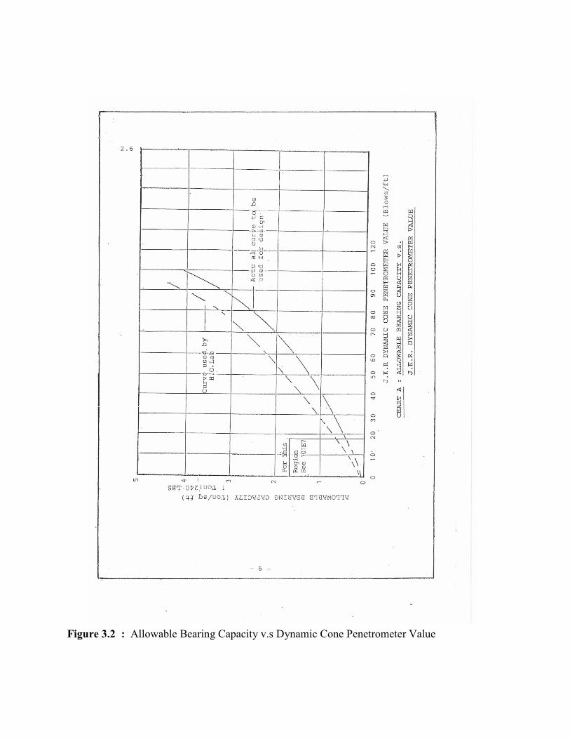
Figure 3.2 : Allowable Bearing Capacity v.s Dynamic Cone Penetrometer Value
3.3 DATA ANALYSIS
Data analysis including bearing capacity calculation and settlement of mat (or
raft) foundation using PLAXIS, were made based on soil properties information
collected from soil investigation works carried out at the above site. Altogether four (4)
member of Deep Borehole and “eight (8) members of Machintosh Probes were carried
out to obtain geotechnical information of the above site. Original design foundation for
project asrama Kelompok Yayasan Terengganu, Besut were used pile foundation
We also use data from Machintoch Probe to use as a measure for the consistency
of cohesive soil and the denseness of granular soil.

CHAPTER 4
CASE STUDY
4.1 INTRODUCTION
Yayasan Terengganu is desirous to develop a new centralized hostel for nearest
schools in Mukim Pelagat as project titled;
“CADANGAN MEMBINA DAN MENYIAPKAN ASRAMA BERKELOMPOK
YAYASAN TERENGGANU DI ATAS LOT PT 4019, MUKIM PELAGAT,
TERENGGANU DARUL IMAN.”
Asrama Berkelompok Yayasan Terengganu (ABYT) is located in the Besut
district of northern Kuala Terengganu with distance almost 115km. By main route
Jerteh – Pasir Puteh, the distance is almost 3 km from Bandar Jerteh. The total area of
this project was 12.4614 acres. The topography of the site is flat land with a small hill in
certain areas.
This report shall be read in conjunction with the soil investigation (SI) factual
report prepared by HANDALAN Enterprise in March 2007.
Focus of this case study is to find out the comparison cost and effect of
geotechnical engineering in replacement of pile foundation with mat foundation (raft)
on the one hostel block in project stated above. The original design on this study case
was using piling methodology. After looking the result of soil from awarded soil
expertise consultant, perhaps a new economical methodology can be approach in this
study case which is raft foundation is a proper method to be highlight.
4.2 SOIL PROFILE
A total of four (4) boreholes had been carried out at the proposed site before the
implementation of ground improvement project. The boreholes locations are shown in
figure 4.1. The subsoil information gathered from the boreholes carried out at the
proposed site showed that, in general, the soil profile comprises of three (3) layers -
figure 4.2
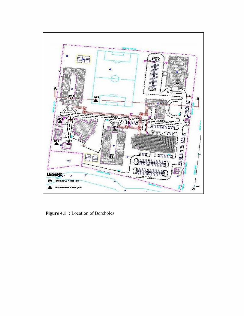
Figure 4.1 : Location of Boreholes

Figure 4.2 : Typical soil profile based on borehole log 3 & 4
Subsoil profile of boreholes 3 and 4 was shown that three (3) layers can be found
based on the result of SPT-N.
First layer was classified as a low stiff soil which SPT-N of about 8 - 9. This layer
was consisted by silty clay and clayey silt with thickness between 0 to 1.5m.
2nd layer is medium stiff to very silty clay or clayey silt. The SPT-N values
generally were in range of 24 to 26.
Layer three (3) more consisted with silt and sand. It’s can be classified as a hard
or very dense soil layer which could encountered at depth 4.5 to 15m. The SPT-N
values were more than 50 blows.
Based on site investigation, it can be summarize that the low dense of soil was
found in certain areas with low thickness of depth. Beside that, almost the area can be
classified as a medium to hard dense soil type. The subsoil information gathered from
the boreholes and subsoil profile along the cross sections as indicated in figure 4.1 and
4.2 are attached in appendix A.
4.3 GROUND WATER
The ground water level fluctuates from the ground surface for borehole 3 and 4,
the water level stated in the Soil Investigation report is 3.8 to 4.20m.
4.4 SOIL PROPERTIES
From the results of site investigation, the consolidation undrained triaxial
compression test shown that the apparent cohesion (C) is 32 kPa with angle of shearing
resistance 15˚ (Deg). The effectiveness stress parameter that we can get from the test,
the cohesion intercept based on effective stress (C’) was 7 kPa with 31˚ (Deg).
The coefficient of consolidation (Cv) of the soft soil layer was obtained from
laboratory test was about 12 to 16 m2/yr. Detail of the laboratory test results are attached
in Appendix B

CHAPTER 5
RESULT AND DISCUSSION
5.1 INTRODUCTION
As mentioned in previous chapter, the level of ground surface and the thickness of
compressible layer vary with the location of the borehole. For the purpose of strength
analysis of soil, the soil profile and soil properties can be simplified as shown in the
appendix B. These results bring us to the main purpose of this paper to analysis
connection between two (2) methodologies of foundation; piling vs raft foundation
methodology. This methodology will influence the construction in aspect of time and
cost.
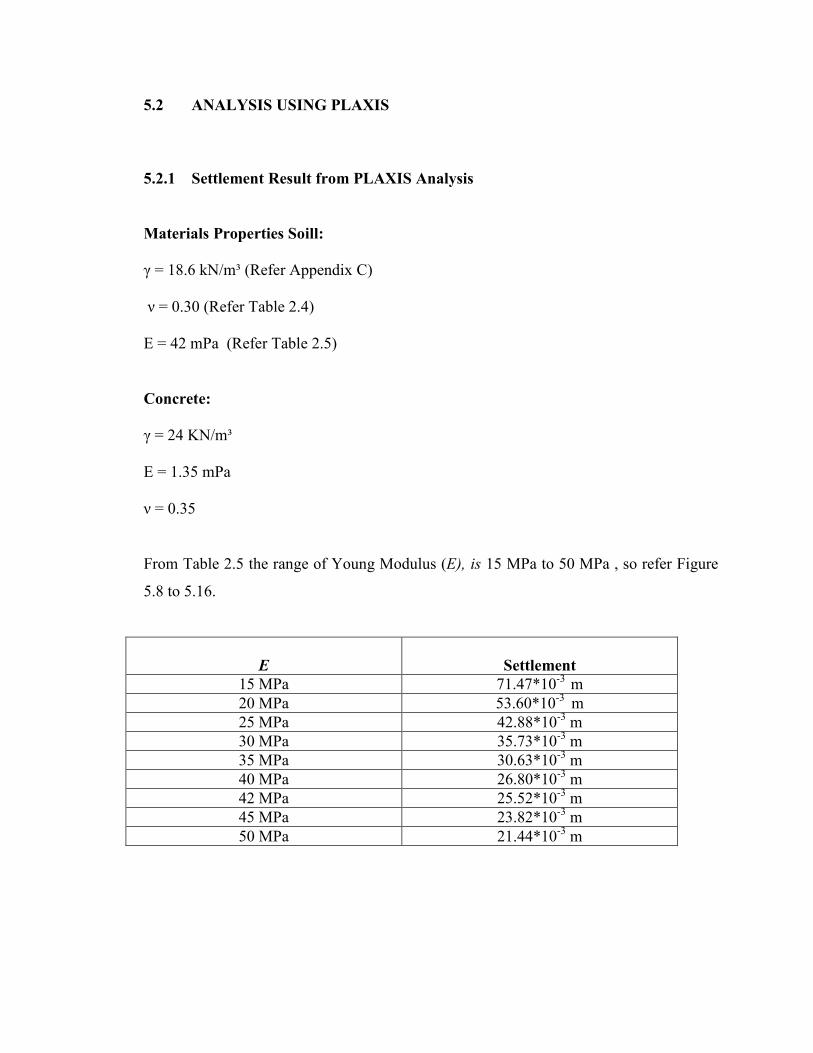
5.2 ANALYSIS USING PLAXIS
5.2.1 Settlement Result from PLAXIS Analysis
Materials Properties Soill:
γ = 18.6 kN/m³ (Refer Appendix C)
ν = 0.30 (Refer Table 2.4)
E = 42 mPa (Refer Table 2.5)
Concrete:
γ = 24 KN/m³
E = 1.35 mPa
ν = 0.35
From Table 2.5 the range of Young Modulus (E), is 15 MPa to 50 MPa , so refer Figure
5.8 to 5.16.
E
Settlement
15 MPa 71.47*10-3 m 20 MPa 53.60*10-3 m 25 MPa 42.88*10-3 m 30 MPa 35.73*10-3 m 35 MPa 30.63*10-3 m 40 MPa 26.80*10-3 m 42 MPa 25.52*10-3 m 45 MPa 23.82*10-3 m 50 MPa 21.44*10-3 m
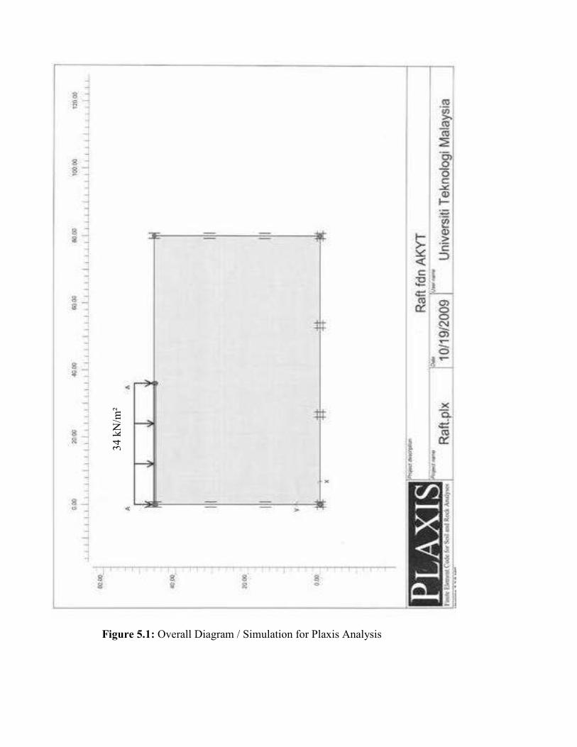
Figure 5.1: Overall Diagram / Simulation for Plaxis Analysis
34 k
N/m
²
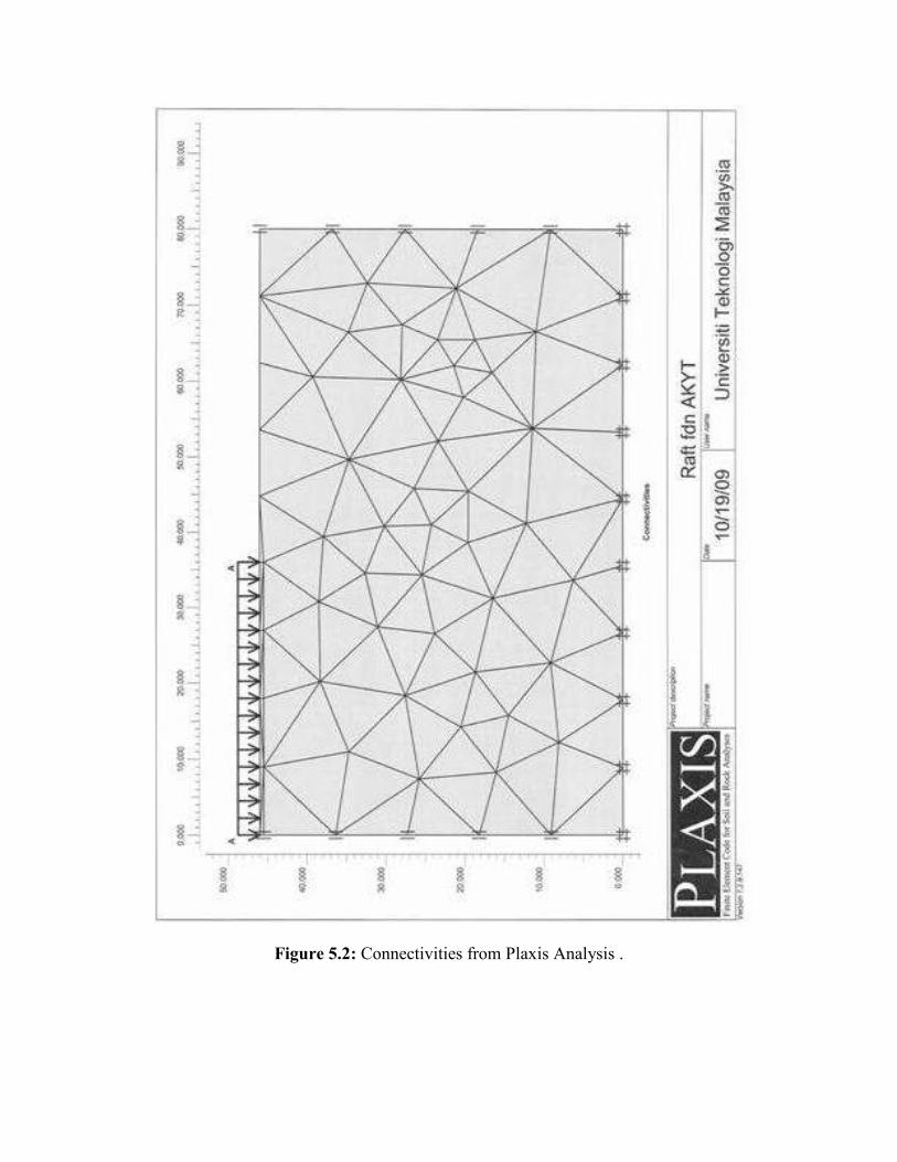
Figure 5.2: Connectivities from Plaxis Analysis .
Figure 5.3: Connectivities from Plaxis Analysis

Figure 5.4: Effective Stresses from Plaxis Analysis .
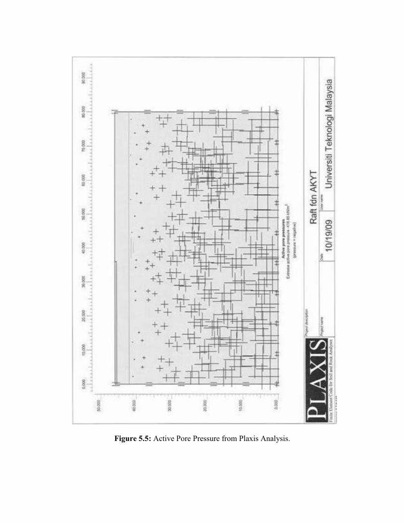
Figure 5.5: Active Pore Pressure from Plaxis Analysis.

Figure 5.6: Deformed Mesh from Plaxis Analysis.

Figure 5.7: Calculation List

Figure 5.8: Total Displacement from Plaxis Analysis for Young Modulus, E = 15 MPa

Figure 5.9: Total Displacement from Plaxis Analysis for Young Modulus, E = 20 MPa

Figure 5.10: Total Displacement from Plaxis Analysis for Young Modulus,
E = 25 MPa
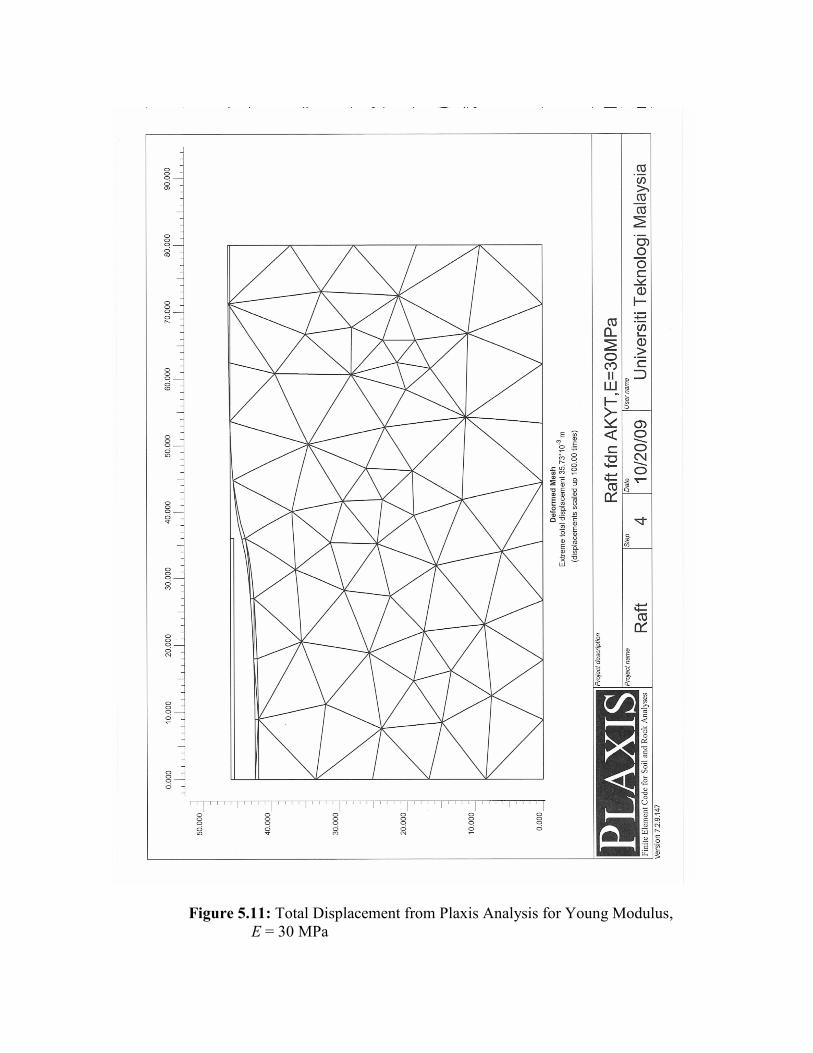
Figure 5.11: Total Displacement from Plaxis Analysis for Young Modulus,
E = 30 MPa
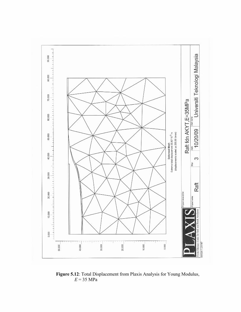
Figure 5.12: Total Displacement from Plaxis Analysis for Young Modulus,
E = 35 MPa

Figure 5.13 :Total Displacement from Plaxis Analysis for Young Modulus,
E = 40 MPa

Figure 5.14: Total Displacement from Plaxis Analysis for Young Modulus,
E = 42 MPa

Figure 5.15: Total Displacement from Plaxis Analysis for Young Modulus,
E = 45 MPa.

Figure 5.16: Total Displacement from Plaxis Analysis for Young Modulus,
E = 50 MPa.

5.3 ESTIMATION OF ALLOWBLE BEARING CAPACITY AND SETTLEMENT BY EMPIRICAL METHODS
5.3.1 Estimation of Bearing Capacity
Estimation of allowable bearing capacity by empirical methods are based on data
from ‘in-situ’ test, which is related to Standard Penetration Test (SPT) with ‘N’ values
and Mackintosh Probe.
5.3.1.1 Using data From Mackintosh Probe Table 5.1 (a): Result of Mackintosh Probe
HANDALAN ENTERPRISE SDN. BHD. MACKINTOSH PROBES
Project : Cadangan Membina Asrama Berkelompok Yayasan Terengganu, Lot PT4019, Mukim Pelagat, Daerah Besut, Terengganu Darul Iman. Supervisor : Asmawi POSITION NO. MP 4 MP 5 MP 6 MP 7 WATER LEVEL Nil Nil Nil Nil DATE OF TEST 4/4/2007 4/4/2007 4/4/2007 4/4/2007 PENETRATION IN METRE
NUMBER OF BLOWS
0.30m 64 68 76 72 0.60m 85 173 200 204 0.90m 128 253 314 288 1.20m 280 400/20cm 400/25cm 400/22cm 1.50m 400/24cm
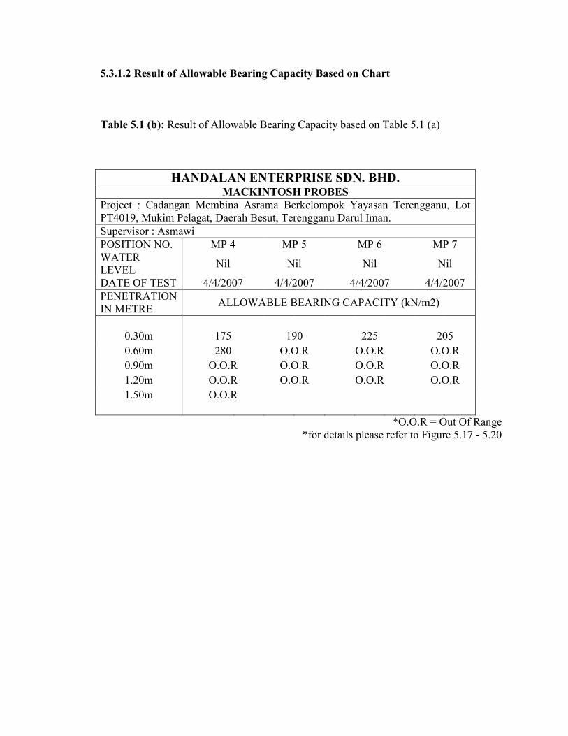
5.3.1.2 Result of Allowable Bearing Capacity Based on Chart
Table 5.1 (b): Result of Allowable Bearing Capacity based on Table 5.1 (a)
HANDALAN ENTERPRISE SDN. BHD. MACKINTOSH PROBES
Project : Cadangan Membina Asrama Berkelompok Yayasan Terengganu, Lot PT4019, Mukim Pelagat, Daerah Besut, Terengganu Darul Iman. Supervisor : Asmawi POSITION NO. MP 4 MP 5 MP 6 MP 7 WATER LEVEL
Nil Nil Nil Nil
DATE OF TEST 4/4/2007 4/4/2007 4/4/2007 4/4/2007 PENETRATION IN METRE
ALLOWABLE BEARING CAPACITY (kN/m2)
0.30m 175 190 225 205 0.60m 280 O.O.R O.O.R O.O.R 0.90m O.O.R O.O.R O.O.R O.O.R 1.20m O.O.R O.O.R O.O.R O.O.R 1.50m O.O.R
*O.O.R = Out Of Range
*for details please refer to Figure 5.17 - 5.20
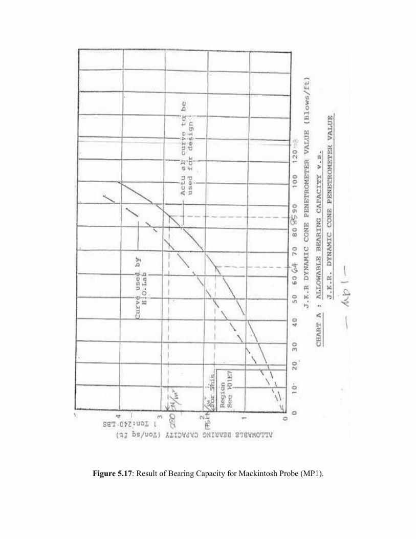
Figure 5.17: Result of Bearing Capacity for Mackintosh Probe (MP1).

Figure 5.18: Result of Bearing Capacity for Mackintosh Probe (MP2).
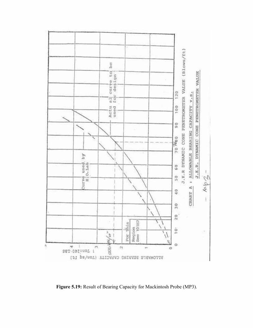
Figure 5.19: Result of Bearing Capacity for Mackintosh Probe (MP3).

Figure 5.20: Result of Bearing Capacity for Mackintosh Probe (MP4).

5.3.1.3 Using Conversion Methods
Using conversion of Mackintosh Probe result to SPT-N value result for granular
and Cohesive Soils according to Prof. Chin Fung Kee
N = 0.091M + 1.8
Where; N = SPT-N Value, total blows count for the last 300mm penetration
M = Mackintosh M-value, total blows count for per foot of penetration
Table 5.2 : Summarize of result according to Prof. Chin Fung Kee
*O.O.R = Out Of Range
*for details please refer to Figure 5.21 - 5.24
BH NO. N at 1.50m Depth (SPT-N Table)
M = (N – 1.8)/0.091
Allowable Bearing Capacity
kN/m2 (from graph)
BH 1 22 222 O.O.R BH 2 21 211 O.O.R BH 3 9 79 240 BH 4 8 68 190

Figure 5.21: Result of Bearing Capacity for Borehole (BH1).
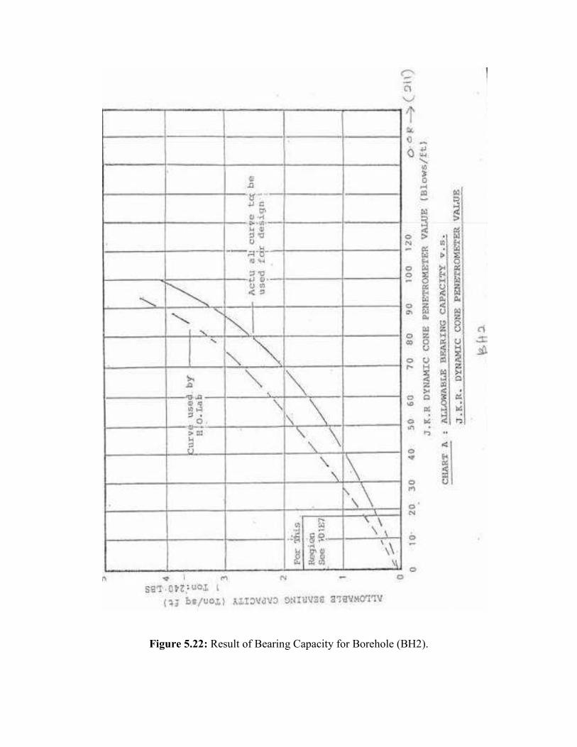
Figure 5.22: Result of Bearing Capacity for Borehole (BH2).
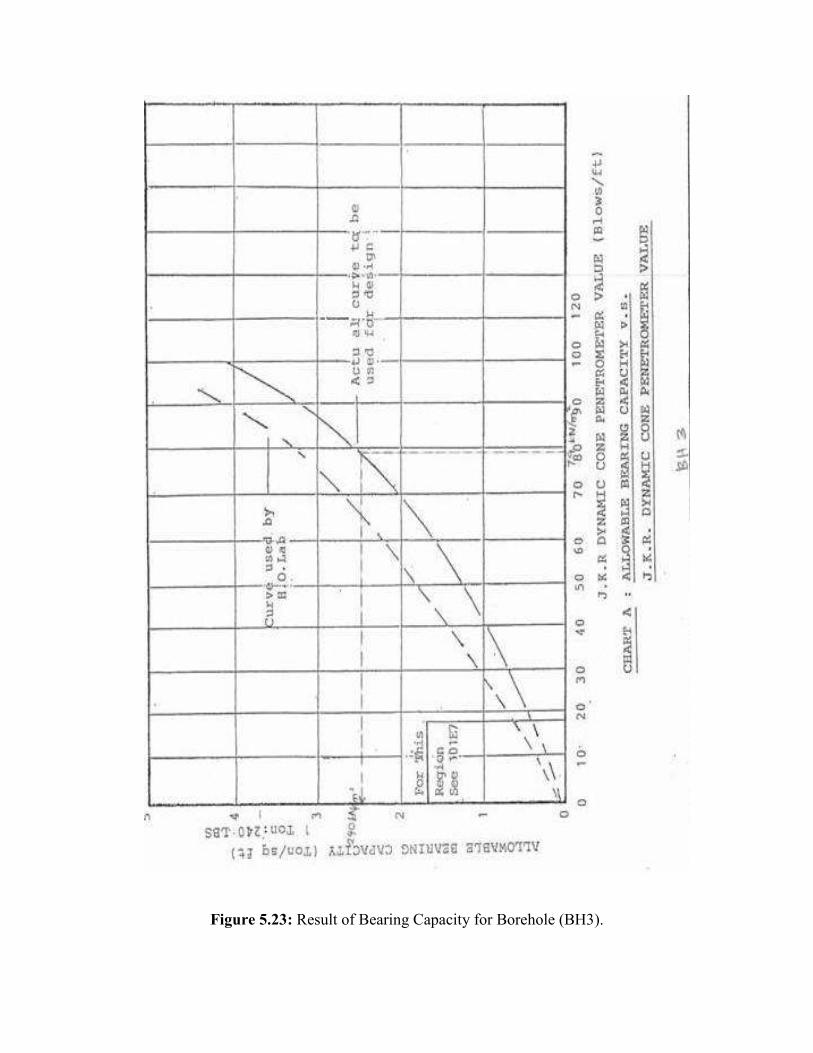
Figure 5.23: Result of Bearing Capacity for Borehole (BH3).
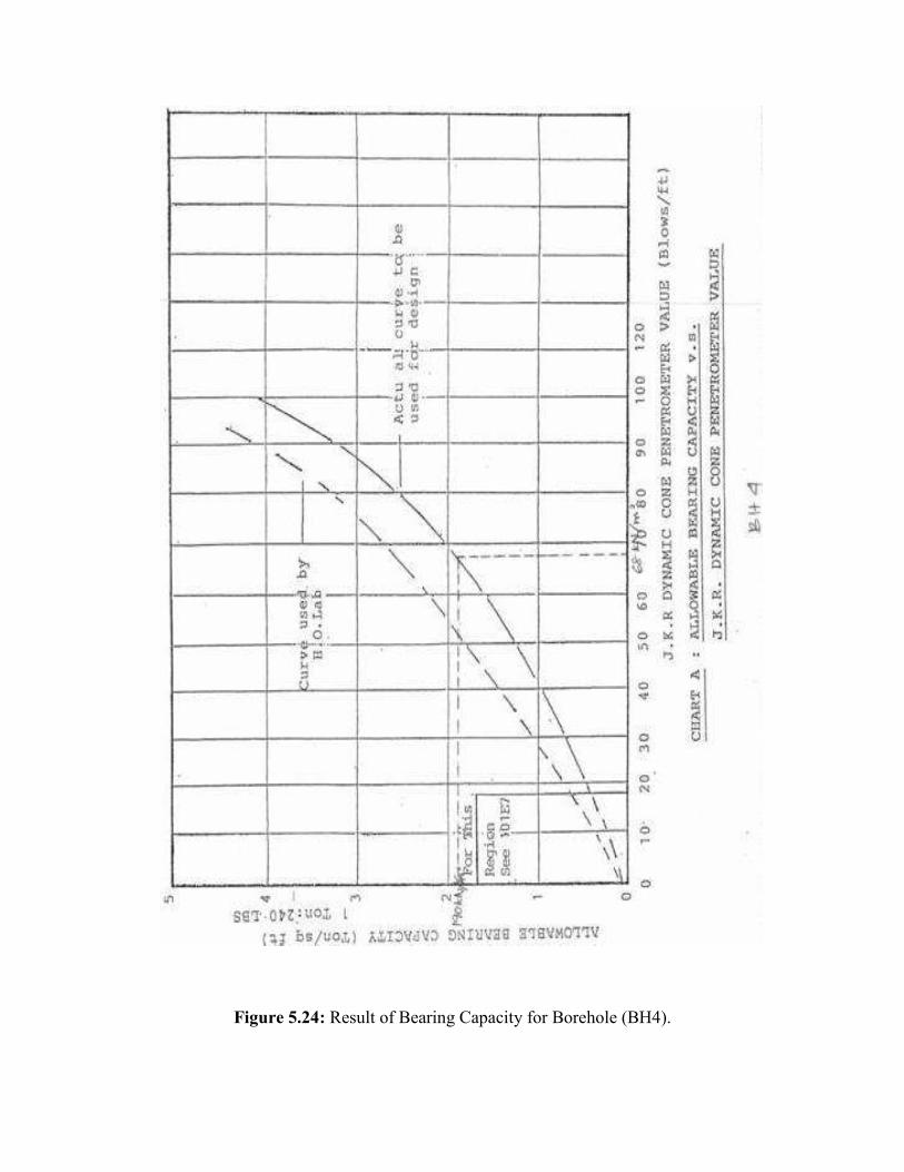
Figure 5.24: Result of Bearing Capacity for Borehole (BH4).

5.4 ESTIMATION OF REQUIREMENT BEARING CAPACITY FOR MAT (OR RAFT) FOUNDATION
5.4.1 Using Equation 2.12 ( For Cohessive Soil )
Based on SPT-N Value and table 5.3 for get Cu
For ; N = 8, Cu = 47.88 , Df = 0.5, B = 36m L = 80m
qnet (u) = 5.14 Cu 1 + 0.195B 1 + 0.4Df
L B
qnet (u) = 5.14 (47.88) 1 + 0.195(36) 1 + 0.4(0.5)
(80) (36)
qnet (u) = 246.10 (1.088) (1.006)
qnet (u) = 269.24 kN/m2
Say that Factor of Safety (F.S) = 2.5
qall (net) = 269.24 = 107.7 kN/m2
2.5 = 108 kN/m2
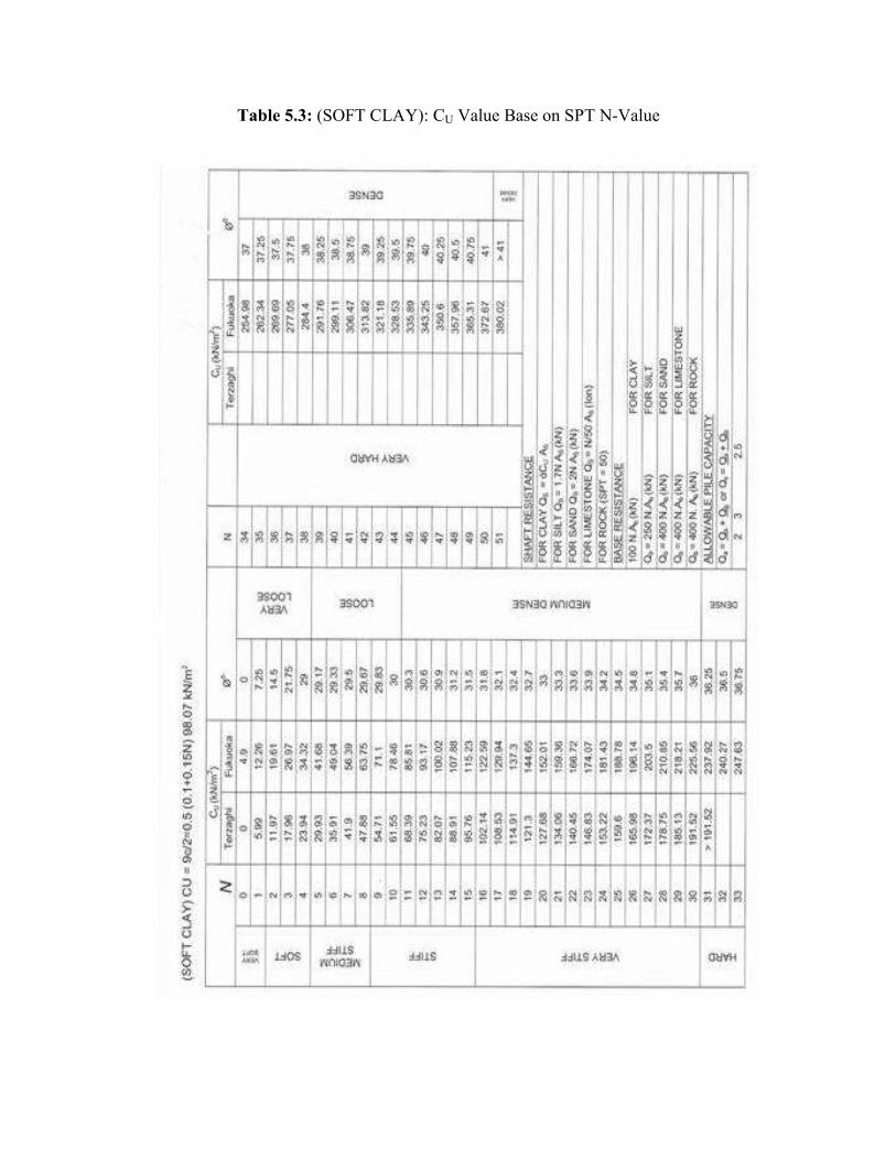
Table 5.3: (SOFT CLAY): CU Value Base on SPT N-Value
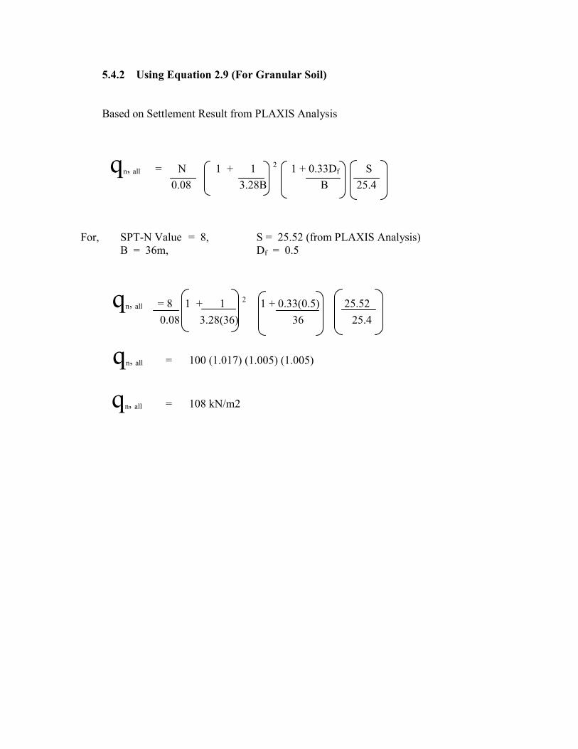
5.4.2 Using Equation 2.9 (For Granular Soil)
Based on Settlement Result from PLAXIS Analysis
qn, all = N 1 + 1 2 1 + 0.33Df S
0.08 3.28B B 25.4
For, SPT-N Value = 8, S = 25.52 (from PLAXIS Analysis) B = 36m, Df = 0.5
qn, all = 8 1 + 1 2 1 + 0.33(0.5) 25.52
0.08 3.28(36) 36 25.4
qn, all = 100 (1.017) (1.005) (1.005)
qn, all = 108 kN/m2
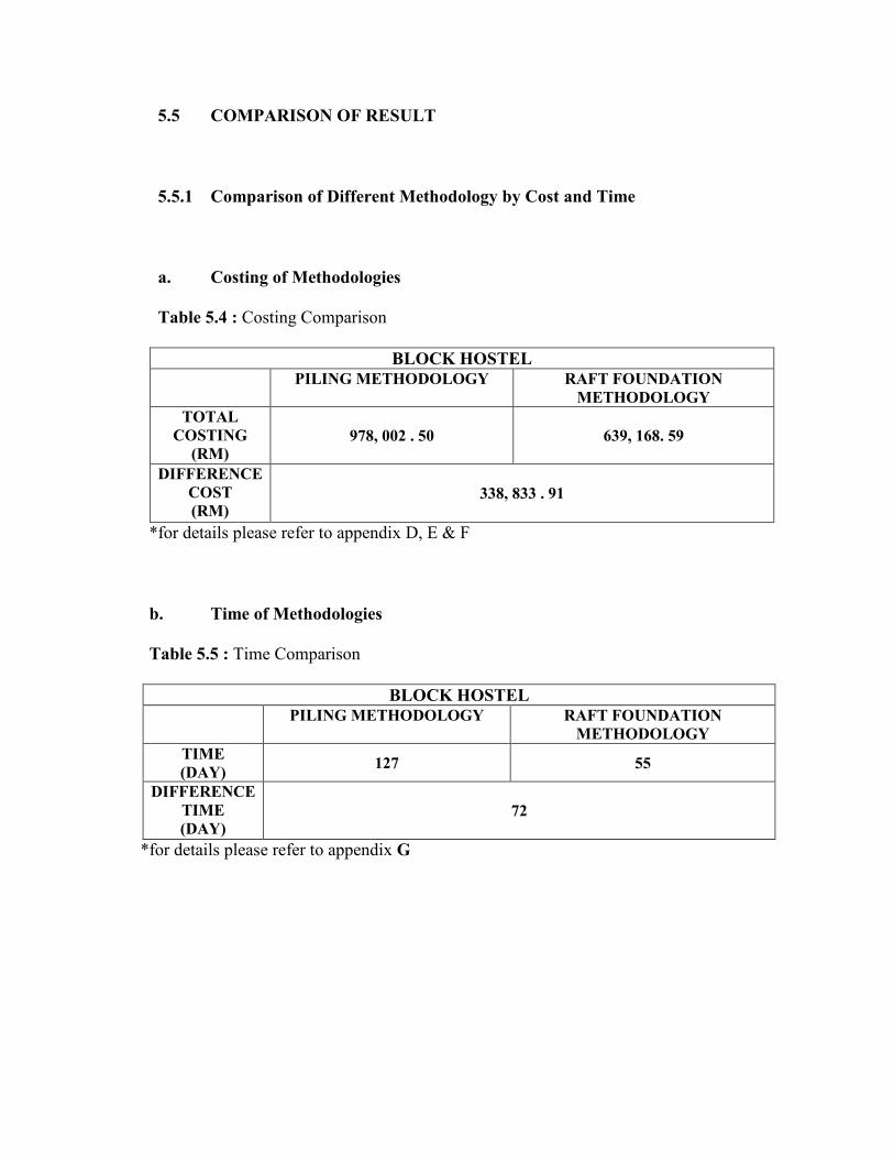
5.5 COMPARISON OF RESULT
5.5.1 Comparison of Different Methodology by Cost and Time
a. Costing of Methodologies Table 5.4 : Costing Comparison
BLOCK HOSTEL
PILING METHODOLOGY RAFT FOUNDATION METHODOLOGY
TOTAL COSTING
(RM) 978, 002 . 50 639, 168. 59
DIFFERENCE COST (RM)
338, 833 . 91
*for details please refer to appendix D, E & F
b. Time of Methodologies
Table 5.5 : Time Comparison
BLOCK HOSTEL PILING METHODOLOGY RAFT FOUNDATION
METHODOLOGY TIME (DAY)
127 55
DIFFERENCE TIME (DAY)
72
*for details please refer to appendix G
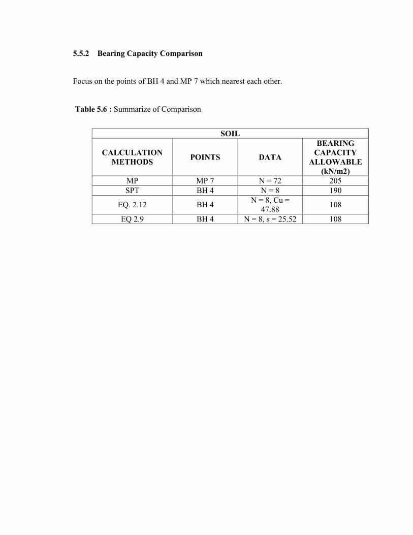
5.5.2 Bearing Capacity Comparison
Focus on the points of BH 4 and MP 7 which nearest each other. Table 5.6 : Summarize of Comparison
SOIL
CALCULATION METHODS
POINTS DATA
BEARING CAPACITY
ALLOWABLE (kN/m2)
MP MP 7 N = 72 205 SPT BH 4 N = 8 190
EQ. 2.12 BH 4 N = 8, Cu =
47.88 108
EQ 2.9 BH 4 N = 8, s = 25.52 108

CHAPTER 6
CONCLUSIONS AND RECOMMENDATIONS
6.1 CONCLUSIONS
From the analysis calculation and graft related to the strength of soil, we can
conclude that;
a) Bearing capacity is about 100 kN/m² in 0 – 1.0 meter depth.
b) Raft foundation can be applied to replacing original design using pilling
methods based on bearing capacity result.
c) The Young Modulus (E) of soil is between 15-50 MPa.

Based on conclusion above; we can see the replacement can bring a lot of benefit
to the client and contractor in aspect:
a) Cost : Cost can be reducing about 35% (RM 338,833.91)
b) Time : Time can be shorten about 57% ( 72 days early )
6.2 RECOMMENDATIONS Common practical for now Civil and Structure (C&S) designer to design any
building under 5 storeys is not involving any geotechnical engineering expertise into their
design process.
They are preferred using piling methods as their foundation design because of safe
solution even it will costly.
So for recommendation, building 3 storeys and above, need to involve
Geotechnical Engineering Expertise to get an efficient and economical approaching for
design any building foundation.

REFERENCES Bowles, Joseph E (1996), Foundation Analysis and Design, 5thEd, Mc-Graw Hill International Edition Donald P. Coduto Donald P, (2001), Foundation Design Principles and Practices Second Edition, Prentice Hall Manjriker Gunaratne (2006). The Foundation Engineering Hand Book. Taylor and Francis Whitlow, R. (2001). Basic Soil Mechanic 4th Edition. Prentice Hall Nurly Gofar and Khairul Anuar Kasim (2007).Introduction to Geotechnical Engineering Part II, Pearson / Prentice Hall Braja M. Das (2000). Foundations of Geotechnical Engineering, Brooks / Cole. Braja M. Das (2000). Fundamentals of Geotechnical Engineering, Brooks / Cole Robert Wade Brown (2001), Practical Foundation Engineering Handbook, 2nd Edition, . Mc-Graw Hill Plaxis 2D, Tutorial Manual Version 9 Soil Investigation Report for Project Asrama Kelompok Yayasan Terengganu, Besut.
( Handalan Enterprise Sdn. Bhd.) Program Latihan Untuk JKR, Pembinaan Asas Cetek, Ikram Sdn. Bhd.