performance evaluation of radio frequency … · performance evaluation of radio frequency...
TRANSCRIPT

IJSRD - International Journal for Scientific Research & Development| Vol. 2, Issue 01, 2014 | ISSN (online): 2321-0613
All rights reserved by www.ijsrd.com 648
Performance Evaluation of Radio Frequency Transmission over Fiber
using Optical Amplifiers
Divya U.1 Sheela Devi Aswathy Chandran
2
1PG Scholar
2Asst. Professor
1, 2Opto Electronics and Communication Systems(E & C Dept.)
1, 2TKM Institute of Technology, Kollam, Kerala, India.
Abstract---The growth of mobile and wireless
communication is increasing the demand for multimedia
services with a guaranteed quality of service. This requires
realization of broadband distribution and access networks.
Radio over Fiber technology has various advantages when it
applies to wireless systems, especially, mobile
communication radio networks. Radio-over-Fiber (RoF)
system mainly uses two modulation techniques ie; direct-
and external-laser modulation. In RoF technology, the fiber
dispersion and chirp parameters are the important
parameters in degrading the performance of optical
communication systems. External modulators of Mach-
Zehnder type minimize the transmission power penalty due
to fiber chromatic dispersion. So these modulators are also
known as chirp-free modulators. Also, better suppression of
nonlinear distortion is achieved by using Mach-Zehnder
external modulator. Data is either externally modulated by
using single-electrode (SEMZM) – and dual electrode
(DEMZM) – Mach-Zehnder modulator. This work presents
a simulation comparison of external modulation schemes
using different optical amplifiers, comparison of received
electric Rf power with different optical amplifiers and
calculation of BER at received channel. Simulation of
external modulation using EDFA and SOA are performed
by using OPTSIM 5.3.
Keywords: Radio over fiber (RoF) system, External
modulation, Dual-and single-electrode MZM, SOA, EDFA
I. INTRODUCTION
Radio-over-Fiber (RoF) techniques are attractive for
realizing high-performance integrated networks. Nowadays,
there is an increasing demand for broadband services which
leads to ever-growing data traffic volumes over these
services. This requires realization of broadband distribution
and access networks. To meet the accelerating demands in
communication systems, the integration of optical network
and wireless radio is a promising solution. ROF means the
optical signal is being modulated at radio frequencies and
transmitted via the optical fiber. The RoF technology has
various advantages when it applies to wireless systems,
especially, mobile communication radio networks [2]. The
central office handles call processing and switching, while
the Base Stations (BS) act as the radio interfaces for the
Mobile Units (MU) or Wireless Terminal Units (WTU). The
BSs may be linked to the central office through either
analogue microwave links or digital fiber optic links. Once
the baseband signals are received at the BS, they are
processed and modulated onto the appropriate carrier. The
radius covered by the signal from the BS is the cell radius.
All the MU/WTU within the cell, share the radio frequency
spectrum. WLANs are configured in a similar fashion, with
the radio interface called the Radio Access Point (RAP).
Figure 1 illustrates the configuration of narrowband wireless
access systems (e.g.GSM).
Fig. 1: Components of a Narrowband Wireless Access
Network
A technology whereby light is modulated by a
radio signal and transmitted over an optical fiber link to
facilitate wireless access is referred to as Radio over Fiber
(RoF). Although radio transmission over fiber is used for
multiple purposes, such as in cable television (CATV)
networks and in satellite base stations, the term RoF is
usually applied when this is done for wireless access. In RoF
systems, wireless signals are transported in optical form
between a central station and a set of base stations before
being radiated through the air. Each base station is adapted
to communicate over a radio link with at least one user's
mobile station located within the radio range of the base
station [3].Radio over fiber (RoF) technology has emerged
as a cost effective approach for reducing radio system costs
because it simplifies the remote antenna sites and enhances
the sharing of expensive radio equipment located at
appropriately sited switching centers (SC) or otherwise
known as central sites/stations (CS).Radio-over-Fiber (RoF)
technology entails the use of optical fiber links to distribute
RF signals from a central location (head-end) to Remote
Antenna Units (RAUs). In narrowband communication
systems and WLANs, RF signal processing functions such
as frequency up-conversion, carrier modulation, and
multiplexing, are performed at the BS or the RAP, and
immediately fed into the antenna. RoF makes it possible to
centralize the RF signal processing functions in one shared
location (head-end), and then to use optical fiber, which
offers low signal loss (0.3 dB/km for 1550 nm, and 0.5
dB/km for 1310 nm wavelengths) to distribute the RF
signals to the RAUs, as shown in Figure 2. By so doing,
RAUs are simplified significantly, as they only need to
perform optoelectronic conversion and amplification.
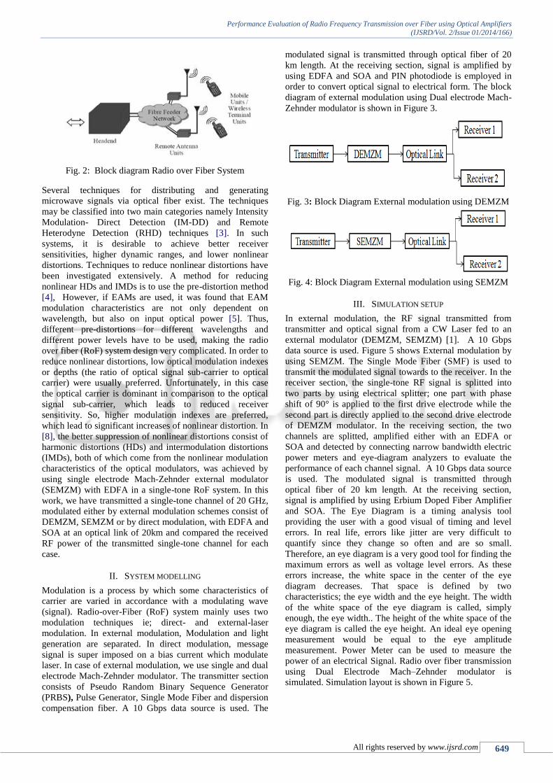
Performance Evaluation of Radio Frequency Transmission over Fiber using Optical Amplifiers
(IJSRD/Vol. 2/Issue 01/2014/166)
All rights reserved by www.ijsrd.com 649
Fig. 2: Block diagram Radio over Fiber System
Several techniques for distributing and generating
microwave signals via optical fiber exist. The techniques
may be classified into two main categories namely Intensity
Modulation- Direct Detection (IM-DD) and Remote
Heterodyne Detection (RHD) techniques [3]. In such
systems, it is desirable to achieve better receiver
sensitivities, higher dynamic ranges, and lower nonlinear
distortions. Techniques to reduce nonlinear distortions have
been investigated extensively. A method for reducing
nonlinear HDs and IMDs is to use the pre-distortion method
[4], However, if EAMs are used, it was found that EAM
modulation characteristics are not only dependent on
wavelength, but also on input optical power [5]. Thus,
different pre-distortions for different wavelengths and
different power levels have to be used, making the radio
over fiber (RoF) system design very complicated. In order to
reduce nonlinear distortions, low optical modulation indexes
or depths (the ratio of optical signal sub-carrier to optical
carrier) were usually preferred. Unfortunately, in this case
the optical carrier is dominant in comparison to the optical
signal sub-carrier, which leads to reduced receiver
sensitivity. So, higher modulation indexes are preferred,
which lead to significant increases of nonlinear distortion. In
[8], the better suppression of nonlinear distortions consist of
harmonic distortions (HDs) and intermodulation distortions
(IMDs), both of which come from the nonlinear modulation
characteristics of the optical modulators, was achieved by
using single electrode Mach-Zehnder external modulator
(SEMZM) with EDFA in a single-tone RoF system. In this
work, we have transmitted a single-tone channel of 20 GHz,
modulated either by external modulation schemes consist of
DEMZM, SEMZM or by direct modulation, with EDFA and
SOA at an optical link of 20km and compared the received
RF power of the transmitted single-tone channel for each
case.
II. SYSTEM MODELLING
Modulation is a process by which some characteristics of
carrier are varied in accordance with a modulating wave
(signal). Radio-over-Fiber (RoF) system mainly uses two
modulation techniques ie; direct- and external-laser
modulation. In external modulation, Modulation and light
generation are separated. In direct modulation, message
signal is super imposed on a bias current which modulate
laser. In case of external modulation, we use single and dual
electrode Mach-Zehnder modulator. The transmitter section
consists of Pseudo Random Binary Sequence Generator
(PRBS), Pulse Generator, Single Mode Fiber and dispersion
compensation fiber. A 10 Gbps data source is used. The
modulated signal is transmitted through optical fiber of 20
km length. At the receiving section, signal is amplified by
using EDFA and SOA and PIN photodiode is employed in
order to convert optical signal to electrical form. The block
diagram of external modulation using Dual electrode Mach-
Zehnder modulator is shown in Figure 3.
Fig. 3: Block Diagram External modulation using DEMZM
Fig. 4: Block Diagram External modulation using SEMZM
III. SIMULATION SETUP
In external modulation, the RF signal transmitted from
transmitter and optical signal from a CW Laser fed to an
external modulator (DEMZM, SEMZM) [1]. A 10 Gbps
data source is used. Figure 5 shows External modulation by
using SEMZM. The Single Mode Fiber (SMF) is used to
transmit the modulated signal towards to the receiver. In the
receiver section, the single-tone RF signal is splitted into
two parts by using electrical splitter; one part with phase
shift of 90° is applied to the first drive electrode while the
second part is directly applied to the second drive electrode
of DEMZM modulator. In the receiving section, the two
channels are splitted, amplified either with an EDFA or
SOA and detected by connecting narrow bandwidth electric
power meters and eye-diagram analyzers to evaluate the
performance of each channel signal. A 10 Gbps data source
is used. The modulated signal is transmitted through
optical fiber of 20 km length. At the receiving section,
signal is amplified by using Erbium Doped Fiber Amplifier
and SOA. The Eye Diagram is a timing analysis tool
providing the user with a good visual of timing and level
errors. In real life, errors like jitter are very difficult to
quantify since they change so often and are so small.
Therefore, an eye diagram is a very good tool for finding the
maximum errors as well as voltage level errors. As these
errors increase, the white space in the center of the eye
diagram decreases. That space is defined by two
characteristics; the eye width and the eye height. The width
of the white space of the eye diagram is called, simply
enough, the eye width.. The height of the white space of the
eye diagram is called the eye height. An ideal eye opening
measurement would be equal to the eye amplitude
measurement. Power Meter can be used to measure the
power of an electrical Signal. Radio over fiber transmission
using Dual Electrode Mach–Zehnder modulator is
simulated. Simulation layout is shown in Figure 5.

Performance Evaluation of Radio Frequency Transmission over Fiber using Optical Amplifiers
(IJSRD/Vol. 2/Issue 01/2014/166)
All rights reserved by www.ijsrd.com 650
Fig. 5: Simulation setup of External modulation using
DEMZM
In external modulation, the RF signal transmitted from
transmitter and optical signal from a CW Laser fed to an
external modulator (DEMZM, SEMZM). Simulation setup
of External modulation using DEMZM is shown in Figure
5.4. In case of external modulation using DEMZM, the
wavelength of continuous wave laser source is 1550.5nm of
laser line width 10MHz with CW power of 10mW. A 10
Gbps data source is used. The single-tone RF signal and the
data source is combined in a combiner and which is splitted
into two parts by using electrical splitter; one part with
phase shift of 90◦ is applied to the first drive electrode while
the second part is directly applied to the second drive
electrode of DEMZM modulator. The offset voltage
corresponding to the zero phase retardation in absence of
any electric field on both electrodes of DEMZM modulator
is set at 5V. The chip factor is kept at zero in case of
DEMZM. The Vpi voltage is fixed at 8.2V. The modulated
signal is transmitted through the fiber at different length. At
the receiving section, signal is splitted and amplified by
using EDFA and SOA and PIN photodiode is employed.
The quantum efficiency and responsivity of PIN diode is
fixed at 0.7199 and 0.9A/W respectively. The output data is
observed through an electroscope and power meter. Radio
over fiber transmission using SEMZM simulation block is
shown in Figure 6.
Fig. 6: Simulation setup of External modulation using
SEMZM
The better quality the digital signal transmission, the more
open white space there should be in the eye. Said
differently, the eye width and eye height should be as large
as possible
Fig. 7: Eye diagram of External Modulation Using DEMZM
obtained from (a) EDFA (b) SOA at 20 Km
Figure7 shows the eye diagram of External modulation
using DEMZM. At 20 Km, Q value and bit error rate of
external modulation using DEMZM with EDFA is 19.7670
and 2.722*10-21
and in case of SOA which is 17.698 and
2.610*10-14
. The signal to noise ratio of the high speed data
signal is also directly indicated by the amount of eye
closure.
Fig. 8: Eye diagram of External Modulation Using DEMZM
obtained from (a) EDFA (b) SOA at 30 Km
Eye height is a measure of the vertical opening of an eye
diagram. Figure 8 shows the eye diagram of External
modulation using DEMZM. At 30 Km, Q value and bit error
rate with EDFA is 16.16 and 2.2*10-10
. In case of SOA
which is 16.14 and 2.00*10-10
.
Fig. 9: Eye diagram of External Modulation Using
DEMZM obtained from (a) EDFA (b) SOA at 40 Km
Figure 9 shows the eye diagram of External modulation
using DEMZM. At 40 Km, Q value and bit error rate of
external modulation with EDFA is 13.87 and 8.38*10-7
. In
case of SOA which is 13.41 and1.26*10-6
.

Performance Evaluation of Radio Frequency Transmission over Fiber using Optical Amplifiers
(IJSRD/Vol. 2/Issue 01/2014/166)
All rights reserved by www.ijsrd.com 651
Fig. 10: RF Power of External Modulation Using DEMZM
obtained from (a) EDFA (b)SOA at 20 Km
In case of external modulation, we can use dual electrode
and single electrode MZM. Figure 10 shows the RF Power
of External Modulation Using DEMZM. At 20 Km, the
measurement of RF power with EDFA is -36.334dB and
SOA which shows -59.3942dB.
Fig. 11: RF Power of External Modulation Using DEMZM
obtained from (a) EDFA (b) SOA at 30 Km
Figure 11 shows the RF Power of External modulation by
using DEMZM with EDFA and SOA at 30 Km. Here, the
RF Power of External modulation with EDFA is-38.19dB
and in case of SOA which is -73.377dB.
Fig. 12: RF Power of External Modulation Using DEMZM
obtained from (a) EDFA(b) SOA at 40 Km.
Figure 12 shows RF Power of External modulation. At 40
Km, RF power DEMZM with EDFA is -41.699dB and the
RF power DEMZM with SOA which is -88.438dB.
Table. 2: Simulation results of DEMZM
In case of external modulation using SEMZM, the
wavelength of continuous wave laser source is 1549.5nm of
laser line width 10MHz with CW power of 10mW. A 10
Gbps data source is used. The single-tone RF signal and the
data source are combined in a combiner and which is
transmitted into the SEMZM modulator and the maximum
transmitted offset voltage is set to zero. The chip factor is
kept at zero in case of SEMZM. The Vpi voltage is fixed at 8V. The modulated signal is transmitted through optical
fiber at different length. At the receiving section, signal is
splitted and amplified by using EDFA and SOA and PIN
photodiode is employed. PIN photodiode is used to convert
optical signal to electrical signal. The quantum efficiency
and responsivity of PIN diode is fixed at 0.7199 and 0.9A/W
respectively. Radio over fiber transmission using SEMZM
simulation setup is shown in Figure 13. The output data is
observed through an electroscope and power meter.
Fig. 13: Simulation setup of External modulation using
SEMZM
Fig. 14: Eye diagram of External Modulation Using
SEMZM obtained from (a)EDFA (b) SOA at 20 Km
Figure 14 shows the eye diagram of External modulation
using SEMZM. At 20 Km, Q value and bit error rate of
external modulation with EDFA is 21.93 and 9.82*10-35
. In
case of SOA which is 12.99 and3.88*10-6
. The bit-error rate
(BER) is defined as
BER = Errors/Total number of bits.
The Q-factor reduction due to inter symbol interference
(ISI), exists due to receiver bandwidth limitation,
nonlinearity of the active components, causes optical power
penalty or error floor in an optical receiver design.

Performance Evaluation of Radio Frequency Transmission over Fiber using Optical Amplifiers
(IJSRD/Vol. 2/Issue 01/2014/166)
All rights reserved by www.ijsrd.com 652
Fig. 15: Eye diagram of External Modulation Using
SEMZM obtained from (a)EDFA (b) SOA at 30 Km
Figure 15 shows the eye diagram of External modulation
using SEMZM. At 30 Km, Q value and bit error rate of
external modulation with EDFA is 19.962 and 1.27*10-21
. In
case of SOA which is 11.733 and5.59*10-5
.
Fig. 16: Eye diagram of External Modulation Using
SEMZM obtained from (a)EDFA (b)SOA at 40 Km
Figure 16 shows the eye diagram of External modulation
using SEMZM. At 40 Km, Q value and bit error rate of
external modulation with EDFA is16.02 and 2.292*10-10
. In
case of SOA which is 10.58 and 3.74*10-4
.
Fig. 17: RF Power of External Modulation Using SEMZM
obtained from (a) EDFA (b) SOA at 20 Km
In SEMZM, which have only one electrode and RF signal
apply in that electrode. Figure 17 shows the RF Power of
External modulation using SEMZM with EDFA and SOA at
20 Km. Here, the RF Power of External modulation with
EDFA is -28.70dB and in case of SOA which is -51.37dB.
Fig. 18: RF Power of External Modulation Using SEMZM
obtained from (a) EDFA (b) SOA at 30 Km.
Figure 18 shows the RF Power measurement of External
modulation. At 30 Km, RF power SEMZM with EDFA is -
31.764dB and RF power with SOA which is -61.06dB.
Fig. 19: RF Power of External Modulation Using SEMZM
obtained from (a) EDFA (b) SOA at 40 Km
Figure 19 shows the RF Power of External Modulation
Using SEMZM. At 40 Km, the measurement of RF power
with EDFA is -33.20dB and SOA which shows -70.84dB.
Table. 3: Simulation results of SEMZM
IV. CONCLUSION
The demands of broadband multimedia services for wireless
users are increasing day by day. ROF (Radio Over Fiber)
technology has become the latest emerging technology to
meet with such demands. The radio over fiber system uses
two types of modulation ie, direct and external modulation.
The modulation techniques with different optical amplifiers
using OptSim simulation are investigated. The comparisons
of both modulation schemes are analyzed. It is found that
the performance of External modulation using SEMZM
modulator with EDFA amplifier is better than DEMZM in
terms of Quality factor, BER and RF power measurement.
REFERENCES
[1] Vishal Sharma, Amarpal Singh, Ajay K. Sharma
“Simulative investigation the impact of optical
amplification techniques on single and dual-electrode
MZM and direct modulator’s in single-tone RoF
system”, Optik - International Journal for Light and
Electron Optics, Feb 2010.
[2] Xavier Fernando, “Radio over Fiber -An Optical
Technique for Wireless Access”, IEEE, Vol 41, Oct
2009.
[3] El-Sayed A. El-Badawy1, Abd El-Naser A. Mohamed,
Ahmed Nabih Zaki Rashed, Mohamed S. F. Tabbour
“New Trends of Radio over Fiber Communication
Systems for Ultra High Transmission Capacity”

Performance Evaluation of Radio Frequency Transmission over Fiber using Optical Amplifiers
(IJSRD/Vol. 2/Issue 01/2014/166)
All rights reserved by www.ijsrd.com 653
International Journal of Communication Networks and
Information Security (IJCNIS),Vol. 3, December 2011.
[4] L. Roselli, V. Borgioni, F. Zepparelli, F. Ambrosi, M.
Comez, P. Faccin, “Analog Laser Predistortion for
Multiservice Radio-Over-Fiber Systems”. IEEE, Vol.
21, Feb 2008.
[5] Karanbir singh “Simulative analysis of OSNR and
received electric Rf power of a rof system having
variable fiber length, using different modulation
techniques and optical amplifiers”, International journal
of engineering science and technology (IJEST), Vol.3,
May 2011.
[6] Ng’oma, Anthony “Radio-over-fibre technology for
broadband wireless communication systems”, Photonic
Network Communications, Vol. 5, June 2005.
[7] Ulrik Gliese, Torben Nørskov Nielsen, Søren Nørskov,
and K. E. Stubkjær, “Multifunctional fiber-optic
microwave links Based on remote heterodyne
detection”, IEEE, Vol. 46, May 1998.
[8] Asish B. Mathews, Dr. Pavan Kumar Yadav,
“Suppression of nonlinearity induced distortions in
radio Over fiber links”, International journal of
electronics and Communication engineering& tech. Vol
5, Nov 2009.