performance evaluation of concrete bridge decks reinforced with mmfx and ssc rebars
TRANSCRIPT

Research Report KTC-06-02/FRT113-01-1F
KENTUCKY
TRANSPORTATION
CENTER
College of Engineering
PERFORMANCE EVALUATION OF CONCRETE BRIDGE DECKS RE-INFORCED WITH MMFX AND SSC REBARS

Research Report
KTC-06-02/FRT113-01-1F
PERFORMANCE EVALUATION OF CONCRETE BRIDGE DECKS RE-
INFORCED WITH MMFX AND SSC REBARS
by
Choo Ching Chiaw Post-doctoral Research Fellow, Department of Civil Engineering
University of Kentucky
and
Issam E. Harik Professor of Civil Engineering and Head, Structures Section,
Kentucky Transportation Center
Kentucky Transportation Center College of Engineering, University of Kentucky
in cooperation with
Transportation Cabinet Commonwealth of Kentucky
and
Federal Highway Administration U.S. Department of Transportation
The contents of this report reflect the views of the authors who are responsible for the facts and accuracy of the data presented herein. The contents do not necessarily reflect the official views or policies of the University of Kentucky, the Kentucky Transportation Cabinet, nor the Federal Highway Administration. This report does not constitute a standard, specification or regulation. Manufacturer or trade names are included for identification purposes only and are not to be considered an endorsement.
January 2006

Technical Report Documentation Page 1. Report No.
KTC-06-02/FRT113-01-1F
2. Government Accession No.
3. Recipient's Catalog No.
5. Report Date
January 2006
6. Performing Organization Code
4. Title and Subtitle
Performance Evaluation of Concrete Bridge Decks Rein-
forced with MMFX and SSC Rebars
7. Author(s): Choo Ching Chiaw and Issam Harik
8. Performing Organization Report No.
KTC-06-02/FRT113-01-1F 10. Work Unit No. (TRAIS)
11. Contract or Grant No.
FRT 113
9. Performing Organization Name and Address
Kentucky Transportation Center College of Engineering University of Kentucky Lexington, Kentucky 40506-0281
13. Type of Report and Period Covered
Final
12. Sponsoring Agency Name and Address
Kentucky Transportation Cabinet State Office Building Frankfort, Kentucky 40622
14. Sponsoring Agency Code
15. Supplementary Notes
Prepared in cooperation with the Kentucky Transportation Cabinet and the U.S. Department of Transpor-tation, Federal Highway Administration.
16. Abstract This report investigates the performance of bridge decks reinforced with stainless steel clad (SSC) and micro-composite multistructural formable steel (MMFX) rebars. The two-span Galloway Road Bridge on route CR5218 over North Elkhorn Creek in Scott County, KY, was reinforced with SSC rebars in one span and MMFX rebars in the second span. The reinforcements are intended to prolong the service life of the newly constructed bridge decks due to the expected corrosion-resistance capability. Moment-curvature analyses indicated that MMFX RC decks had 57% and 85% higher strengths than SSC RC decks in positive and negative moment regions, respectively. The areas under the moment-curvature curves, a ductility indicator, of the MMFX RC decks, however, were 5% and 14% less than that of SSC RC decks in similar regions. Field performance of the bridge decks was monitored beginning in August 2001, following its completion in July 2001. Field evaluation consists of locating and measuring crack formation. As of September 2005, the cracks in the deck were not measurable since the maximum observed crack width was less than the smallest unit (e.g. 1/100 in.) on the crack comparator. This is also less than the maximum crack width (0.013 in.) allowed by the AASHTO Standard for exterior exposure. 17. Key Words Bridge Decks, Corrosion Resistance, Stainless Steel Clad (SSC), Microcomposite Multistructural Formable Steel (MMFX), Crack Width
18. Distribution Statement
Unlimited with approval of
Kentucky Transportation Cabinet
19. Security Classif. (of this report) Unclassified
20. Security Classif. (of this page) Unclassified
21. No. of Pages 25
22. Price
-
Form DOT 1700.7(8-72) Reproduction of Completed Page Authorized

I
TABLE OF CONTENTS LIST OF TABLES II LIST OF FIGURES III EXECUTIVE SUMMARY IV ACKNOWLEDGMENTS VI 1.0 INTRODUCTION 1 1.1 Background 1 1.2 Reinforcement Alternatives for Concrete Bridge Decks 1 1.3 Stainless Steel Clad (SSC) and Microcomposite Multistructural Formable Steel (MMFX) Reinforcing Bars 3 1.4 Objective and Scope 4 2.0 SSC AND MMFX CONCRETE BRIDGE DECKS 5 2.1 Stress-strain Characteristics of SSC and MMFX Steels 5 2.2 The CR5218 Bridge over North Elkhorn Creek, Scott County, KY 7 2.3 Moment-Curvature Analyses of SSC and MMFX RC Decks 9 2.4 Conclusion and Recommendation 11 3.0 FIELD INVESTIGATION 13 3.1 Deck Inspection and Monitoring 13 3.2 Field Investigation Results 15 4.0 SUMMARY AND CONCLUSION 16 REFERENCES

II
LIST OF TABLES Table 2.1 Comparison of Ultimate Moment Strengths and Developed Tensile Strains in Reinforcements of SSC and MMFX RC Decks 12

III
LIST OF FIGURES Figure 2.1 Stress-Strain Characteristic of SSC Steels 5 Figure 2.2 Stress-Strain Characteristic of MMFX Steels 6 Figure 2.3 Two-Span CR 5218 Bridge in Scott County, KY 7 Figure 2.4 Bridge Deck Cross Section Showing Reinforcement Layout 7 Figure 2.5 Bridge Elevation View and Slab Plan 8 Figure 2.6 Theoretical Moment-Curvature (Mn-φ) Plot Per Slab Width in the Positive Moment Regions of the Concrete Decks 9 Figure 2.7 Theoretical Moment-Curvature (Mn-φ) Plot Per Slab Width in the Negative Moment Regions of the Concrete Decks 10 Figure 3.1 Inspection and Monitoring Area on CR 5218 Bridge 13 Figure 3.2 Typical Bridge Inspection Form 14 Figure 3.3 Bridge Deck Inspection as of August 1, 2003 15

IV
EXECUTIVE SUMMARY
The structural performance of concrete bridge decks reinforced with stainless steel clad (SSC) or microcomposite multistructural formable steel (MMFX) rebars is re-ported herein. The bridge is located on Galloway Road on route CR5218 over the North Elkhorn Creek in Scott County, KY. This report describes the details pertaining to the following aspects: (1) experimental results of the tensile tests of SSC or MMFX rebars; (2) analytical investigation and results of concrete bridge decks reinforced with SSC or MMFX rebars, and (3) field performance evaluation of concrete bridge decks reinforced with SSC or MMFX rebars.
SSC and MMFX rebars are new breed of steel expected to possess excellent cor-rosion-resistance capability. Uni-axial tensile tests were carried out to determine the me-chanical properties of SSC and MMFX rebars prior to using in the Galloway Road Bridge. The results showed that (1) the typical stress-strain behavior of SSC rebars re-sembled that of the conventional steel rebars with a well-defined linearly-elastic and plas-tic response, and (2) the stress-strain relation of MMFX rebars is nonlinear. The nonlin-ear stress-strain relation of MMFX rebars is modeled using the Richard-Blalock expres-sion. Details of SSC and MMFX stress/strain relations and characteristics are presented herein.
The concrete decks of the two-span bridge on Galloway Road on route CR5218 over North Elkhorn Creek in Scott County, KY, were originally intended to be reinforced with steel rebars. As part of a demonstration program, the steel rebars were replaced with SSC rebars in one span and MMFX rebars in the other span. Analytical moment-curvature analyses showed that the MMFX RC Decks possess higher moment strength than SSC RC Decks, i.e. 57% and 85% higher in positive and negative moment regions, respectively. However, the area under the moment-curvature curves, a ductility indicator, of the MMFX RC decks are 5% and 14% lower than that of SSC decks in respective re-gions.
Monitoring of concrete bridge spans with decks reinforced with SSC or MMFX rebars began in August 2001, following its completion in July 2001. Monitoring and field inspections included the determination of crack formation, location, and magnitude (i.e. width and length). As on September 23, 2005, cracks in the deck were not measur-able since the maximum observed crack width was less than the smallest unit (e.g. 1/100 inch) on the crack comparator. This is acceptable since the maximum allowed crack width by the AASHTO Standard Specification is 0.013 in for exterior exposure.

V
ACKNOWLEDGMENTS Financial support for this project was provided by the Federal Highway Admini-stration and the Kentucky Transportation Cabinet.
The authors would like to acknowledge the help provided by the following stu-dents: Brandon Taylor, Robert Goodpaster, Michael Davidson, and Scott Pabian.
1
1.0 INTRODUCTION 1.1 Background
The rapid deterioration of concrete reinforcing components (e.g. concrete struc-tures constructed with conventional ASTM A615 low carbon billet steels or A706 low-alloy steels as reinforcing) due to corrosion, is a major problem. One of the causes is the wide-spread use of salt-based de-icing chemicals, e.g. sodium chloride (NaCl), which contains chloride ions. Krauss and Rogalla (1996) cited that as much as 2.5 to 5.0 tons per lane per mile of de-icing chemicals have been reportedly used on bridge decks in many US states every year. The cost of repairing or replacing deteriorated structures could be more than $20 billion annually and the cost is rising every year (Smith and Vir-mani 1996). For example, according to the National Bridge Inventory database (2002), the bridge improvement cost for the state of Kentucky alone was reported to be approxi-mately $1.8 billon for the fiscal year of 2002.
Concrete, by nature, is strong and durable. Adequate depth of concrete cover can
serve as a protective coating to the underlying reinforcing steels. However, the perme-able nature of concrete, e.g. air pores, allows the infiltration and accumulation of chloride ions (Cl-) from road salt in concrete. When the chloride ions reach a threshold level, in the presence of water or moisture (H2O) and oxygen (O2), they will break through the passive layers of oxidized ferrous (Fe2+) and ferric (Fe3+) protecting the reinforcing steels, a mechanism known as depassivation, and that initiates the corrosion process of reinforc-ing steels (Brown 2002, Clemeña 2002, and Thomas 2002). Low-permeability concrete produced by adding pozzolanic materials such as fly ash, silica fume, or slag, to concrete mix, the addition of corrosion inhibitor [e.g. Calcium nitrite, Ca(NO2)2] to concrete, pro-viding adequate depth of concrete cover, or any combination thereof has also been sug-gested by various researchers (Knoll 2002, and Rosenberg 1999). However, this may be impossible since concrete also has the tendency to crack, often under service conditions or even at an earlier age. Therefore, when cracks occur, the reinforcing bars will still be left unprotected. Ultimately, the use of corrosion-resistant reinforcements may still be the only/most effective solution. 1.2 Reinforcement Alternatives for Concrete Bridge Decks
In general, a coating that prevents chloride ions and moisture from reaching the reinforcing steels in concrete will prevent corrosion. To minimize corrosion of the rein-forcing steels and the corresponding delaminations and spalling of concrete, many trans-portation departments started using Epoxy-coated steel (ECS) bars in the 1970s.
Today, epoxy-coated steel bars are widely available and are still extensively used.
Epoxy-coated steel bars, if handled properly, can prevent corrosion. However, epoxy-coated steel rebar is not the perfect solution to corrosion: (Brown 2002, Clemeña 2002, Pape and Fanous 1998, Rosenberg 1999, Sohanghpurwala and Scannell 1999, and Wio-leta et. al. 2000): (1) Coating tends to get damaged or nicked during fabrication, transpor-tation, and handling; and (2) delamination or debonding occurs between coating and steel

2
bar. As a result, the exposed areas or the debonded coatings allow chloride ions, mois-ture, and oxygen to reach the steel and to initiate the corrosion process. From an investi-gation sponsored by the Virginia Transportation Research Council (Wioleta et. al. 2000), where 18 bridge decks in the range of 2 to 20 years old were examined, a conclusion stated that debonding of epoxy coating occurred in all but one deck. The study also re-vealed that the reinforcing bars in various stages of debonding showed visible signs of corrosion, suggesting that epoxy-coated steel bars will provide little or no additional ser-vice life for concrete bridge decks in comparison to bare steels. Chloride attack was also reported on the Florida Long Key Bridge (Wioleta et. al. 2000, and Rosenberg 1999). In one examination, for instance, it was discovered that the epoxy shell was left intact as all the steel underneath the coating had corroded away.
Fiber reinforced polymer (FRP) bars will not corrode; hence FRP bars provide a viable option as a reinforcement alternative (Benmokrane et. al. 1999, Deitz et. al. 1999, and GangaRao et. al 1997). FRP reinforcing bars can effectively serve as a solution to the corrosion problem; however, FRP reinforcing is cost-prohibited. In addition, reported in Better Roads Magazine (2001), FRP reinforcing bars are non-weldable and cannot be mechanically spliced, which presents important design differences and construction con-sideration. Moreover, the moduli of elasticity of various FRP reinforcing bars are often lower compared to that of reinforcing steels. Lower moduli of elasticity can limit the de-sign span lengths and/or require more bars to be used. In some instances, the high alka-linity (pH 12.5 – 13.5) of concrete can degrade any exposed glass fibers – one of many available FRP types. Though FRP reinforcing bar has the advantage of having a higher strength-to-weight ratio than the conventional steel, its light-weight presents a possibility of flotation problems during concrete placement as the density (γf < 100 lb/ft3 or 1600 kg/m3) of most FRP reinforcing bars is in general smaller compared to that of normal wet concrete (γc = 150 lb/ft3 or 2400 kg/m3) (GangaRao et. al. 1997).
Many types of solid stainless steels, e.g. stainless 304 and 316 (Austenitic group) or 430 (Ferritic group) or 318 (Ferritic-Austenitic or Duplex) steels, have also been de-veloped to resist different corrosion environments and working conditions. In general, a stainless steel bar is essentially a low carbon steel which contains chromium (Cr) at 10% or more by weight. Chromium in steel allows the formation of a rough, adherent, invisi-ble, corrosion-resisting chromium oxide film on the steel surface; this protective film, if damaged, is self-healing. Hurley and Scully (2002) reported that solid stainless 316LN steel reinforcing bars have a higher chloride threshold level (100 times greater) – the critical chloride concentration required to initiate the corrosion process of reinforcing bars – than conventional A615 carbon steel bars which typically have a reported Cl-/OH- molar ratio of 1.0 or lesser. Their calculations also showed a fifty-fold increase in time required until the initiation of chloride induced corrosion for stainless steels compared to carbon steels in concrete with 2 in. (50 mm) cover. Various studies have concluded that stainless steel bars can provide over 75 years of corrosion-free service life for concrete structures, however, like FRP reinforcing bars, their use has been limited due to the high initial cost [$2.30/lb installed compared to $0.50/lb installed for carbon steel bars (Cle-meña 2002)].

3
1.3 Stainless Steel Clad (SSC) and Microcomposite Multistructural Formable Steel (MMFX) Reinforcing bars
The Kentucky Transportation Cabinet is currently experimenting with stainless steel clad (SSC) reinforcing bars by Stelax and microcomposite multistructural formable steel (MMFX) by MMFX, Inc. in bridge decks of a two-span bridge located on Galloway Road, Scott County, KY.
SSC reinforcing bars are essentially carbon steel bars (e.g. A615 Grade 40, 60, etc) serving at the core with a stainless steel exterior. The stainless steel provides a pro-tective coating or cladding (e.g. epoxy-coated or galvanized reinforcing bars). SSC rein-forcing bars are metallurgically bonded by, first, pressing the carbon steel core into a stainless steel pipe and then hot-rolling the stainless steel clad bars under a specified tem-perature. The SSC reinforcing bars combine most of the advantages of solid stainless steel equivalents [such as an equivalent corrosion resistance, resulting in an equally long service life (75 or more years)] and the mechanical properties of their carbon steel core bars, which means that their use in bridge decks could be acceptably considered a direct substitution. Hurley and Scully (2002) concluded that the chloride threshold for 316L clad bar was strongly dependent on the protection provided to the carbon steel core at the cut end of the rebar. They further added that the chloride threshold level of 316L clad bar with properly covered ends is similar to that of a solid stainless steel bar, 316LN. Similar findings were concluded in a study done by Darwin et. al. (2002) for Type 304 stainless steel clad reinforcing bars. Since the stainless steel cladding is tough, it does not have the inherent weaknesses of the organic coating used in the epoxy-coated bars, making them as resistant to chloride attack (Clemeña 2002, and Hurley and Scully 2002). Clemeña (2002) noted that SSC reinforcing bars cost slightly more than half that of carbon steel, making SSC reinforcing a realistic alternative to conventional reinforcement. Cost analy-sis based on a 75-year economic life performed by Darwin et al. (2002) found that stainless steel clad steel has the lowest overall cost among other reinforcement types: conventional carbon steels, epoxy-coated steels, and galvanized steels. This is largely due to the fact that all other type of reinforcements would require repairs after about 25 years.
Another viable alternative to carbon steels or epoxy-coated steels is MMFX steels. Without the use of coating technologies (e.g. epoxy-coated or stainless steel clad steel bars), the excellent corrosion resistance of MMFX steels is a result of the patented chemical composition and proprietary steel microstructure of the material. This unique feature minimizes the formation of micro galvanic cells – corrosion is an electrochemical process involving galvanized corrosion cells – in the steel structure. Since MMFX steels are not coated, they do not require any special handling and are not susceptible to damage at construction sites or during transportation. According to the manufacturer, MMFX steel has a low carbon content (less than 1%) and contains around eight to ten percent chrome, and the company claims that the negligible amount of nickel makes MMFX steel economical to produce.
4
1.4 Objective and Scope
New reinforcement types, Stainless Steel Clad and Microcomposite Multistruc-tural Formable Steels, were used to construct the concrete bridge decks of the CR 5218 Bridge over North Elkhorn Creek on Galloway Road located in Scott County, KY. MMFX steels were employed in Span 1 while SSC steels were placed in Span 2 of the structure, respectively. The decks were initially designed to be steel reinforced. There-fore, the primary objective is to investigate the performance of SSC and MMFX RC decks. The scopes of this study include: (1) experimental studies of the stress-strain be-haviors of SSC and MMFX steels; (2) moment-curvature analyses of SSC and MMFX reinforced concrete decks; and (3) field investigation of SSC and MMFX RC decks.

5
2.0 SSC AND MMFX CONCRETE BRIDGE DECKS 2.1 Stress-strain Characteristics of SSC and MMFX Steels
The stress-strain characteristics of several reinforcement alternatives have been experimentally studied (Hill et. al. 2003). The reinforcement alternatives included Ep-oxy-Coated Steel (ECS), Carbon Fiber Reinforced Polymer (CFRP), Stainless-Steel Clad (SSC), and Microcomposite Multistructural Formable Steel (MMFX) reinforcing bars.
The experimental stress-strain behaviors of four SSC steel bars are shown in Fig. 2.1. Similar to conventional carbon steels (e.g. ASTM A615 or A706 steels), a typical stress-strain curve of SSC steel bars exhibits an initial linear elastic portion up to a well-defined yield point, a yield plateau, and a nonlinear strain hardening region. The yield stresses of these SSC steels are approximately 61 x 103 psi (427 MPa). The modulus of elasticity was determined to be 29 x 106 psi (200 GPa). Since the onset of strain harden-ing regions varies from one bar to another, this nonlinear region will be ignored in the moment-curvature analysis (i.e. the stress-strain relationship of SSC required for mo-ment-curvature analyses will assume to be linearly-elastic and perfectly-plastic).
Fig. 2.1 – Stress-strain characteristic of SSC steels (Hill et. al. 2003)
The experimental stress-strain characteristics of MMFX steels in tension were de-termined and are presented graphically (Fig. 2.2). The stress-strain curves of MMFX steel resemble that of pre-stressing steel strands. The stress-strain curves are initially lin-ear but then highly nonlinear at higher stress levels (Hill et. al. 2003). Typically, MMFX steels have higher strength when compared to SSC steels (for comparison purposes, stress-strain curves of SSC-1A are included in Fig. 2.2). However, unlike SSC steels, MMFX steels lack a distinct yield point.
0
20
40
60
80
100
0.00 0.01 0.02 0.03 0.04Axial strain, ε (in/in)
Axi
al S
tress
, σ (k
si)
SSC-1A
SSC-1B
SSC-2A
SSC-2B
Yield Points
Yield Plateau (Vary)
Strain Hardening (Vary)

6
Fig. 2.2 – Stress-strain characteristic of MMFX steels (Hill et. al. 2003)
To model the stress-strain behavior of MMFX steels, the Richard and Blalock (1969) expression is used:
nn
tkt E
EE
E
E1
11
⎪⎪
⎭
⎪⎪
⎬
⎫
⎪⎪
⎩
⎪⎪
⎨
⎧
⎥⎥⎥⎥
⎦
⎤
⎢⎢⎢⎢
⎣
⎡
+⎟⎠
⎞⎜⎝
⎛ −+
=
εσ
ε
εσ (2.1)
The different parameters contained in the above expression have the following
definitions and values:
E = Initial modulus of elasticity of MMFX steels = 29,500 ksi (207 GPa) Et = Post-yield elastic modulus of MMFX steels = 250 ksi (1750 MPa) n = Characteristic exponential = 2.0 ε = Tensile strain (in/in) σ = Tensile stress (ksi or MPa) σk = Characteristic yield stress = 170 ksi (1190 MPa) This expression in Eq. 2.1 gives a maximum tensile stress of 178.5 ksi (1250 MPa) at a corresponding tensile strain of 0.04 in/in, and it will be used in the moment-curvature analyses.
0
40
80
120
160
200
0.00 0.02 0.04 0.06 0.08
Axial strain, ε (in/in)
Axi
al s
tress
, σ
(ksi
)
MMFX-1A
MMFX-1B
MMFX-2A
Richard-Blalock
SSC-1A
7
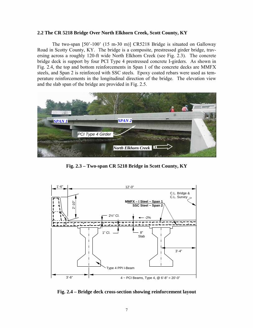
2.2 The CR 5218 Bridge Over North Elkhorn Creek, Scott County, KY
The two-span [50’-100’ (15 m-30 m)] CR5218 Bridge is situated on Galloway Road in Scotty County, KY. The bridge is a composite, prestressed girder bridge, trav-ersing across a roughly 120-ft wide North Elkhorn Creek (see Fig. 2.3). The concrete bridge deck is support by four PCI Type 4 prestressed concrete I-girders. As shown in Fig. 2.4, the top and bottom reinforcements in Span 1 of the concrete decks are MMFX steels, and Span 2 is reinforced with SSC steels. Epoxy coated rebars were used as tem-perature reinforcements in the longitudinal direction of the bridge. The elevation view and the slab span of the bridge are provided in Fig. 2.5.
Fig. 2.3 – Two-span CR 5218 Bridge in Scott County, KY
Fig. 2.4 – Bridge deck cross-section showing reinforcement layout
C.L. Bridge & C.L. Survey
1’-6” 12’-0”
3’-6”
4 ~ PCI Beams, Type 4, @ 6’-8” = 20’-0”
3’-4”
2½” Cl.
1” Cl. 8” Slab
-2%
2’-1
0” MMFX – I Steel ~ Span 1
SSC Steel ~ Span 2
Type 4 PPI I-Beam
SPAN 1 SPAN 2
North Elkhorn Creek
PCI Type 4 Girder

8
ELEV
ATI
ON
VIE
W
50’ –
100
’ PC
I Bea
m, T
ype
4 H
S25
Liv
e Lo
ad
PLA
N O
F SL
AB
103
~ M
MFX
– I
Ste
els
@ 6
” = 5
1’-0
” (T
op &
Bot
tom
of S
lab)
20
3 ~
SS
C S
teel
s @
6” =
101
’-0”
(Top
& B
otto
m o
f Sla
b)
C.L
. Brid
ge &
C
.L. S
urve
y
C.L
. Abu
t. 1
50’-0
” Spa
n 1
100’
-0” S
pan
2
C.L
. Abu
t. 2
C.L
. Pie
r 1
App
roxi
mat
e S
olid
Roc
k Li
ne
App
roxi
mat
e G
roun
d Li
ne
KY
227
Sta
mpi
ng G
roun
d U
.S. 4
60 G
eorg
etow
n
Bot
. of F
tg.
Ele
v. 9
43.5
70’
Bot
. of F
tg.
Ele
v. 9
43.5
70’
MM
FX –
I S
teel
MM
FX –
I S
teel
S
SC
Ste
el
SS
C S
teel
152’
-9” (
Out
to O
ut o
f Brid
ge)
Fig.
2.5
– B
ridg
e el
evat
ion
view
and
slab
pla
n
9
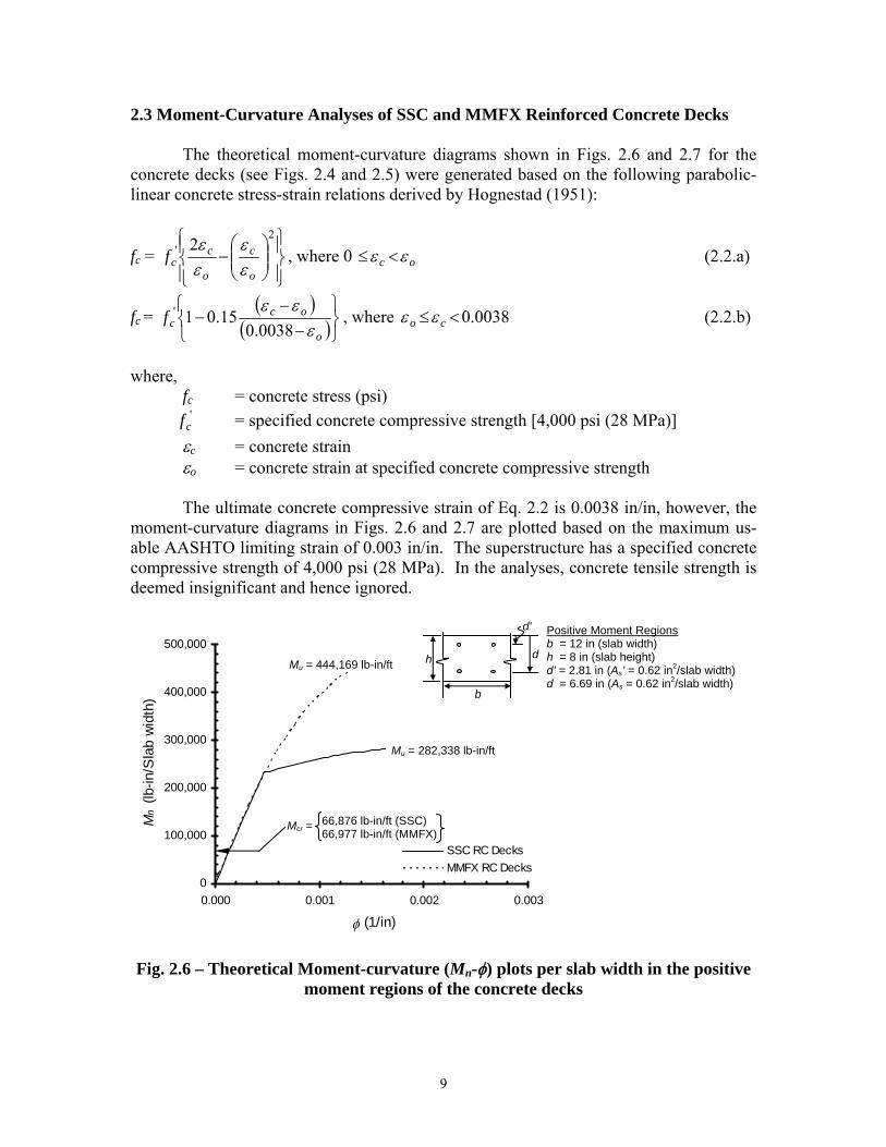
2.3 Moment-Curvature Analyses of SSC and MMFX Reinforced Concrete Decks The theoretical moment-curvature diagrams shown in Figs. 2.6 and 2.7 for the concrete decks (see Figs. 2.4 and 2.5) were generated based on the following parabolic-linear concrete stress-strain relations derived by Hognestad (1951):
fc = ⎪⎭
⎪⎬⎫
⎪⎩
⎪⎨⎧
⎟⎟⎠
⎞⎜⎜⎝
⎛−
2' 2
o
c
o
ccf
εε
εε
, where 0 oc εε <≤ (2.2.a)
fc = ( )
( )⎭⎬⎫
⎩⎨⎧
−−
−o
occf
εεε
0038.015.01' , where 0038.0<≤ co εε (2.2.b)
where, fc = concrete stress (psi) '
cf = specified concrete compressive strength [4,000 psi (28 MPa)] εc = concrete strain εo = concrete strain at specified concrete compressive strength The ultimate concrete compressive strain of Eq. 2.2 is 0.0038 in/in, however, the moment-curvature diagrams in Figs. 2.6 and 2.7 are plotted based on the maximum us-able AASHTO limiting strain of 0.003 in/in. The superstructure has a specified concrete compressive strength of 4,000 psi (28 MPa). In the analyses, concrete tensile strength is deemed insignificant and hence ignored. Fig. 2.6 – Theoretical Moment-curvature (Mn-φ) plots per slab width in the positive
moment regions of the concrete decks
Positive Moment Regions b = 12 in (slab width) h = 8 in (slab height) d’ = 2.81 in (As’ = 0.62 in2/slab width)d = 6.69 in (As = 0.62 in2/slab width)
b
h d
d'
0
100,000
200,000
300,000
400,000
500,000
0.000 0.001 0.002 0.003
φ (1/in)
Mn (l
b-in
/Sla
b w
idth
)
SSC RC DecksMMFX RC Decks
Mcr = 66,876 lb-in/ft (SSC) 66,977 lb-in/ft (MMFX)
Mu = 444,169 lb-in/ft
Mu = 282,338 lb-in/ft
10
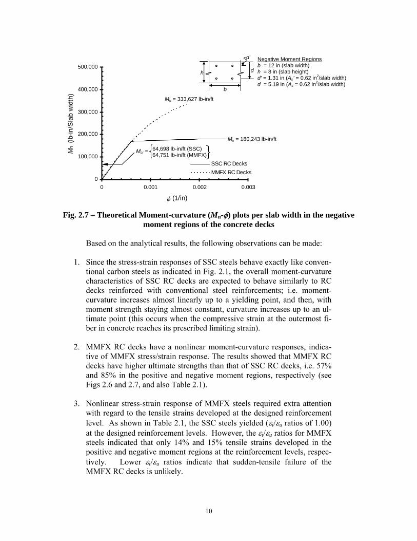
Fig. 2.7 – Theoretical Moment-curvature (Mn-φ) plots per slab width in the negative
moment regions of the concrete decks
Based on the analytical results, the following observations can be made:
1. Since the stress-strain responses of SSC steels behave exactly like conven-tional carbon steels as indicated in Fig. 2.1, the overall moment-curvature characteristics of SSC RC decks are expected to behave similarly to RC decks reinforced with conventional steel reinforcements; i.e. moment-curvature increases almost linearly up to a yielding point, and then, with moment strength staying almost constant, curvature increases up to an ul-timate point (this occurs when the compressive strain at the outermost fi-ber in concrete reaches its prescribed limiting strain).
2. MMFX RC decks have a nonlinear moment-curvature responses, indica-
tive of MMFX stress/strain response. The results showed that MMFX RC decks have higher ultimate strengths than that of SSC RC decks, i.e. 57% and 85% in the positive and negative moment regions, respectively (see Figs 2.6 and 2.7, and also Table 2.1).
3. Nonlinear stress-strain response of MMFX steels required extra attention
with regard to the tensile strains developed at the designed reinforcement level. As shown in Table 2.1, the SSC steels yielded (εt/εu ratios of 1.00) at the designed reinforcement levels. However, the εt/εu ratios for MMFX steels indicated that only 14% and 15% tensile strains developed in the positive and negative moment regions at the reinforcement levels, respec-tively. Lower εt/εu ratios indicate that sudden-tensile failure of the MMFX RC decks is unlikely.
Negative Moment Regions b = 12 in (slab width) h = 8 in (slab height) d’ = 1.31 in (As’ = 0.62 in2/slab width)d = 5.19 in (As = 0.62 in2/slab width)
b
h d
d'
0
100,000
200,000
300,000
400,000
500,000
0 0.001 0.002 0.003
φ (1/in)
Mn (l
b-in
/Sla
b w
idth
)
SSC RC DecksMMFX RC Decks
Mcr = 64,698 lb-in/ft (SSC) 64,751 lb-in/ft (MMFX)
Mu = 333,627 lb-in/ft
Mu = 180,243 lb-in/ft

11
4. To obtain a general idea of the ductility, the areas under the moment-curvature diagrams of SSC and MMFX RC decks were computed. It is es-timated that the moment-curvature areas of MMFX RC decks are 5% and 14% less than the moment-curvature areas of SSC RC decks in the posi-tive and negative moment regions, respectively.
2.4 Conclusion and Recommendation
Moment-curvature analyses were carried out to study concrete bridge decks of the CR 5218 Bridge reinforced with SSC and MMFX steels. The bridge decks were origi-nally designed to be reinforced with conventional carbon steels. Therefore, the one-to-one replacement of reinforcement justified such an investigation.
Due to its higher strength, MMFX RC decks, in general, have higher moment ca-pacities compared to SSC RC decks when the amount of reinforcement is directly substi-tuted. A closer examination indicated that the tensile strains developed at the reinforce-ment levels were 15% or less for MMFX steels compared to its ultimate/limiting tensile strain. Note that the ultimate/limiting strain of MMFX steels for this study was assumed to be 0.04 in/in. In terms of ductility, the areas of the moment-curvature curves of MMFX RC decks were slightly lower compared to that of SSC RC decks.
The performance of MMFX RC decks compares favorably to the SSC RC decks (or conventional steel RC decks). However, due to MMFX’s nonlinear response and, to a certain extent, the lack of a distinct yield point merits extra attention when designing with such reinforcing. The results showed that direct substitution or replacement may under-utilize the high-strength potential of such decks, in addition to being an excellent corro-sion deterrent.
12
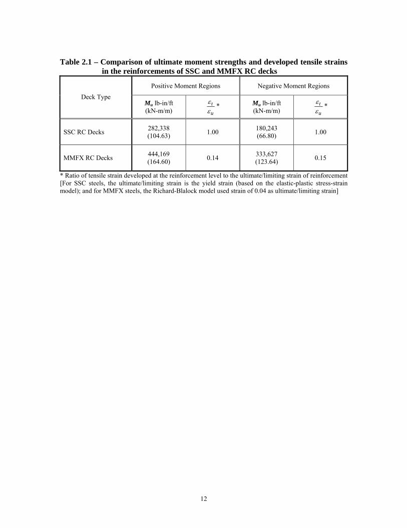
Table 2.1 – Comparison of ultimate moment strengths and developed tensile strains
in the reinforcements of SSC and MMFX RC decks
Positive Moment Regions Negative Moment Regions
Deck Type Mu lb-in/ft (kN-m/m) u
tεε * Mu lb-in/ft
(kN-m/m) u
tεε *
SSC RC Decks 282,338 (104.63) 1.00 180,243
(66.80) 1.00
MMFX RC Decks 444,169 (164.60) 0.14 333,627
(123.64) 0.15
* Ratio of tensile strain developed at the reinforcement level to the ultimate/limiting strain of reinforcement [For SSC steels, the ultimate/limiting strain is the yield strain (based on the elastic-plastic stress-strain model); and for MMFX steels, the Richard-Blalock model used strain of 0.04 as ultimate/limiting strain]

13
3.0 FIELD INVESTIGATION 3.1 Deck Inspection and Monitoring
The field inspection and monitoring process of the CR 5218 Bridge has been car-
ried out and will continue at regular intervals. The purpose of these processes is to de-termine whether or not the bridge is safe and sustainable at serviceable conditions. Since SSC and MMFX steels are relatively new and have the potential to become an alternative to conventional reinforcement, the monitoring and inspection procedures provide valu-able data and information for future research.
To evaluate the performance of the concrete bridge deck, a designated area has been selected as shown in Fig. 3.1. The square area [10’-0” x 10’-0” (3 m x 3 m)] is fur-ther divided into a 1 ft2 (≈ 0.1 m2) grid for detailed crack inspection. It can be seen that the grid area covers the positive and negative moment regions of the concrete bridge deck as it is supported by two prestressed concrete girders.
Fig. 3.1 – Inspection and monitoring area on CR 5218 Bridge
The inspection process is carried out by performing the following tasks:
1. The designated area is first cleaned using a high-pressured water system to remove debris.
2. Basic data such as date, time, temperature, and humidity at the site is taken
down. A sample of the data recording sheet is provided in Fig. 3.2.
50’-0” Span 1
27’-0
”
RC Barrier
RC Barrier
Georgetown KY 227 Stamping Ground
C.L. Bridge & C.L. Survey
10’-0”
Nor
th E
lkho
rn C
reek
C.L. Pier 1
10’-0” C.L. of PCI Girders

14
3. From one grid to another, magnifying glasses are used to locate any
cracks. The location, length, and width of such cracks are recorded if any are found.
Fig. 3.2 – Typical bridge inspection form
7 8 9 4 5 6 1 2 3
J
I
F
G
H
C
D
E
10
A
B
1’
1’
US
460
Geo
rge-
tow
n K
Y 22
7 St
ampi
ng
Gro
und
Date: Time: Temperature: Humidity:

15
3.2 Field Investigation Results
Bridge deck inspections of the SSC and MMFX RC bridge decks began in July 2002. Thus far, six such inspections have been conducted, the latest on August 1, 2003. The bridge decks are reportedly in excellent condition as cracks are undetectable or im-measurable. The latest round of inspection is shown in Fig. 3.3:
Fig. 3.3 – Bridge deck inspection on August 1, 2003.
7 8 9 4 5 6 1 2 3
J
I
F
G
H
C
D
E
10
A
B
1’
1’
US
460
Geo
rge-
tow
n K
Y 22
7 St
ampi
ng
Gro
und
Date: Time: Temperature: Humidity:
Additional notes/comments:
August 1, 2003
12:00
80.8oF
37%
Crack widths are immeasurable
12”
12”
6” 8”
12”
4”
6”

16
4.0 SUMMARY AND CONCLUSION
The performance of a two-span bridge located on Galloway Road of route CR 5218 over Elkhorn Creek in Scott County, KY, is reported herein. The concrete bridge decks originally to be steel reinforced were reinforced in one span with SSC rebars, and MMFX rebars in the other. The intent of these reinforcements was to prolong the service life of the bridge decks, because of the high corrosion-resistibility of these rebars. Prior to the implementation, uni-axial tensile tests were carried out on SSC and MMFX specimens. The results indicated that SSC steels have a well-defined linear elas-tic-and-plastic stress-strain response similar to those of conventional mild steels. The experimental yield strength of SSC steels was approximately 61 ksi (420 MPa). The MMFX reinforcing bars, however, have a nonlinear stress-strain relationship with con-siderably higher strength at ultimate (i.e. 3 times as high). The stress-strain behavior of SSC steels is modeled as linearly-elastic-and-plastic, whereas MMFX steels is modeled using the Richard-Blalock expression in the moment-curvature analyses.
Moment-curvature analyses were carried out on SSC and MMFX bridge decks. Since SSC steels are essentially conventional steels coated with stainless steel, the SSC reinforced bridge decks have similar moment-curvature characteristics of conventional steel reinforced decks. The MMFX reinforced bridge decks exhibit higher moment ca-pacity due to its considerable high tensile strength; 57% and 85% higher in the positive and negative moment regions, respectively. The area under the moment-curvature curves, a ductility indicator, of MMFX RC bridge decks was smaller compared to SSC RC bridge decks; 5% and 14% in respective regions. Overall, the one-to-one substitution of conventional steel with MMFX may not be warrant.
Monitoring of crack formation, location, length and width was carried out on spe-cific intervals beginning in August 2001. As of September 23, 2005, the cracks in the decks were not measurable since the observed crack width was less than the smallest unit (1/100 in.) on the crack comparator. This is also less than the maximum allowed crack width of 0.013 in. prescribed in AASHTO Standard Specification for exterior exposure.

17
References Pape, J. and Fanous, F., “Impact of Bridge Deck Cracking on Durability,” Transportation Conference Proceedings. 1998. Krauss, P.D. and Rogalla, E.A., “Transverse Cracking in Newly Constructed Bridge Decks,” Report 380, National Cooperative Highway Research Program. 1996. Smith, J.L. and Virmani, Y.P., “Performance of Epoxy-Coated Rebars in Bridge Decks,” FHWA Report Vol. 60 No. 2, Federal Highway Administration. Washington D.C., 1996. National Bridge Inventory (NBI) Report 2002. Clemeña, G.G., “Testing of Selected Metallic Reinforcing Bars for extending the Service Life of Future Concrete Bridges: Summary of Conclusions and Recommendations,” Final Report (Report No. VTRC 03-R7), Virginia Transportation Research Council, Char-lottesville, Virginia. 2002. Brown, M.C., “Corrosion Protection Service Life of Epoxy Coated Reinforcing Steel in Virginia Bridge Decks,” Doctoral Dissertation, Virginia Polytechnic Institute and State University, Blacksburg, Virginia. 2002. Thomas, M., “Determining the Corrosion Resistance of Steel Reinforcement for Con-crete,” Correspondence note to MMFX Technologies, University of New Brunswick, Frederiction, NB, Canada. 2002. Knoll, H., “NRC Studies Corrosion Inhibitors for Reinforcing Steel in Concrete,” The Ottawa Construction News, Vol. 12 No. 11, IRC – National Research Council Canada. 2002. Rosenberg, A., “How to Prevent Corrosion in Precast Concrete,” Technical Section – Manufactured Concrete, National Precast Concrete Association, Indianapolis, IN. 1999. Sohanghpurwala, A.A. and Scannell, W.T., “Condition and Performance of Epoxy-Coated Rebars in Bridge Decks,” Public Roads, Federal Highway Administration, Wash-ington D.C. 1999. Wiolet. A. P., Weyers, R.E., Weyers, R.M., Mokarem, D.W., Zemajtis, J., Sprinke, M.M., and Dillard, J.G., “Field Performance of Epoxy-Coated Reinforcing Steel in Vir-ginia Bridge Decks,” Final Report (VTRC 00-R16), Virginia Transportation Research Council, Charlottesville, Virginia. 2000. Benmokrane, B., Masmoudi, R., Chekired, Rahman, H., Debbache, Z., and Tadros, G., “Design, Construction, and Monitoring of Fiber Reinforcing Polymer Reinforced Con-crete Bridge Deck,” Fourth International Symposium – Fiber Reinforced Polymer Rein-
18
forcement for Reinforced Concrete Structures, ACI International SP-188, Farmington Hills, MI. 1999. Deitz, D.H., Harik, I.E., and Gesund, H., “One-way Slabs Reinforced with Glass Fiber Reinforced Polymer Reinforcing Bars,” Fourth International Symposium – Fiber Rein-forced Polymer Reinforcement for Reinforced Concrete Structures, ACI International SP-188, Farmington Hills, MI. 1999. GangaRao, H., Thippeswamy, H.K., Kumar, S.V., and Franco, J.M., “Design, Construc-tion, and Monitoring of the First FRP Reinforced Concrete Bridge Deck in the United States,” Proceedings of the Third International Symposium on Non-Metallic (FRP) Rein-forcement for Concrete Structures – Vol. 1, Japan Concrete Institute, Tokyo, Japan. 1997. “Stainless-Clad Rebar: Cost-Effective Corrosion Protection,” Better Roads Magazine – For the Government/Contractor Project Team, June 2001. Hurley, M.F. and Scully, J.R., “Chloride Threshold Levels in Clad 316L and Solid 316LN Stainless Steel Rebar,” CORROSION 2002, National Association of Corrosion Engineers (NACE), Paper No. 02224. 2002. Darwin, D., Kahrs, J.T., and Locke, C.E., “Evaluation of Corrosion Resistance of Type 304 Stainless Steel Clad Reinforcing Bars,” Research Report (FHWA-KS-02-3), Kansas Department of Transportation and the University of Kansas, KS. 2002. Hill, C., Choo, C.C., and Harik, I.E., “Reinforcement Alternatives for Concrete Bridge Decks” Research Report (KTC-03-19/SPR-215-00-1F), Kentucky Transportation Center and University of Kentucky, July 2003. Hognestad, E., “A Study of Combined Bending and Axial Load in Reinforced Concrete Members,” Bulletin Series No. 399, University of Illinois Engineering Experiment Sta-tion, 1951, 46p.