performance comparison of dimple pleat separator and
TRANSCRIPT
Performance Comparison of Dimple Pleat Separator and Ribbon Separator
Radial Flow HEPA Fi l ters.
Paxton K. Gi f f in, M ichael S. Parsons, John A. Wi lson, and Charles A. Waggoner
Insti tute for Clean Energy Technology M ississippi State Universi ty
32nd Nuclear A i r Cleaning Conference June 17-19, 2012
Denver, CO

Introduction AG-1 Fi l ter Qual i f ication
– Currently no Qual i f ied Fi l ters – TWG Cri tical ly Reviewed Qual i f ication Status
Existing Data – Dated (1990) – Limi ted Particle Size Distribution – Limi ted Characterization
Need for Fi l ter Li fecycle Loading Data Need for Testing at Condi tions Representative of Actual Use (Elevated Temperature & Relative Humidi ty Condi tions)
2

Dimple Pleat Separators
3
A B C D
Filter Type Safe Change
Remote Change
# of Pleats 345 330 Media (m2) 29.73 29.17 Interior Diameter (cm) 33.02 27.94
– M anufacturer : Flanders Fi l ters – Rated Flow: 56.6m3/min (2000 CFM ) – Two Versions: Safe Change (A & B) and
Remote Change (C & D)
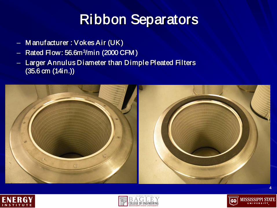
Ribbon Separators – M anufacturer : Vokes Ai r (UK) – Rated Flow: 56.6m3/min (2000 CFM ) – Larger Annulus Diameter than Dimple Pleated Fi l ters
(35.6 cm (14in.))
4

Fi l ter Separators
Dimple Pleat Ribbon Separated
5

Ambient Temperature/RH
6

Elevated Temperature/RH
7

Test Data Presented
8

Chal lenge Aerosol PSD
9

M ass Loading Curves Ambient Condi tions – Dimple Pleated Fi l ters
10
0
2
4
6
8
10
12
0 1000 2000 3000 4000 5000 6000 7000 8000
Diff
eren
tial P
ress
ure
(KPa
)
Mass (grams)
Safe Change - Carbon Black
Safe Change - Carbon Black
Remote Change - Carbon Black
Remote Change - Carbon Black
Remote Change - AZ Road Dust
Remote Change - AZ Road Dust
Safe Change - AZ Road Dust
Remote Change - Alumina
Safe Change - Alumina
Remote Change - Alumina

Ambient Condi tions – M ass Loading Curve Comparison
11
800g 1000g
1500g

Ambient Condi tion Resul ts Fi l tering Ef f iciency and Downstream Concentration vs. Di f ferential Pressure
Chal lenge Aerosol : A lumina
12

Ambient Condi tion Resul ts Penetration Curves
13
300 nm

Elevated Condi tion Resul ts Dimple Pleat Fi l ter Tests
14

Elevated Condi tion Resul ts Ribbon Separator Fi l ter Tests
15

Dimple Pleat Testing Images
16

Ribbon Separator Testing Images
17

18
Post Rupture Images Dimple Pleat Fi l ter – Ambient Condi tions

19
Post Rupture Images Dimple Pleat Fi l ter – Elevated Temperature and Relative
Humidi ty

Post Rupture Images Ribbon Separator Fi l ter
20

Conclusions
Resul ts Comparison – M ass Loading Capaci ty – Fi l tering Ef f iciency – Elevated Condi tion Performance – Resistance to Rough Handl ing – Fi l ter Pack Endurance
Appl ication Considerations Recommendation for Future Testing
21

Acknowledgement
22
We acknowledge the support of this work under DOE Cooperative Agreement
DE-FC01-06EW07040.

23

Damaged Ribbon Pleat Fi l ter Fi l ter was shipped in a box, not a crate. Fi l ter has thinner gauge metal for protective gri l l and strengthening bands. Less physical ly robust as dimple pleat f i l ters manufactured by Flanders. This f i l ter was used for ambient condi tions loading capaci ty test, which was outside of the ini tial scope of work for ribbon pleat f i l ter testing.
24

OLD SLIDES
25

Image Safe Change Fi l ter Col lected at 28.3 m3/min (1000cfm) af ter Rupture
26

Remote Change Test 1
27
0
10
20
30
40
50
60
70
80
90
0
2
4
6
8
10
12
14
12:57:36 13:12:00 13:26:24 13:40:48 13:55:12
Tem
pera
ture
(ºC
) and
Rel
ativ
e H
umity
(%)
Diff
eren
tial P
ress
ure
(kPa
)
Time
First Remote Change Filter Test Elevated Conditions Portion of Testing
Differentail Pressure Elevated Related Humidity Elevated Temperature Elevated

Safe Change Test 1
28
0
10
20
30
40
50
60
70
0
2
4
6
8
10
12
11:42:43 11:54:14 12:05:46 12:17:17 12:28:48 12:40:19
Tem
pera
ture
(ºC
) and
Rel
ativ
e H
umid
ity (%
)
Diff
eren
tial P
ress
ure (
kPa)
Time
Differential Pressure, Humidity, and Temperature vs. Time Safe Change Elevated Conditions Test Filter
Elevated Portion of Testing
Differential Pressure Temperature Relative Humidity

Conclusions
ACFM vs SCFM Separator Issues – Dimple Pleat & Elevated RH and T – Losing Rigidi ty and Dimples relax
Large Aspect Ratio of the Pleats
29

AG-1 Radial Flow Representative Fi l ters
Two Versions Tested – Remote Change – Safe Change
Dimple Pleat
30
Remote Change
Safe Change
Filter Type Safe Change
Remote Change
# of Pleats 345 330 Media (m2) 29.73 29.17 Interior Diameter (cm) 33.02 27.94

31
Testing Condi tions – Ambient
Temp: 15.6 to 26.7ºC (60 to 80ºF) RH: 40 to 60% Load wi th aerosol unti l f i l ter rupture or 12.5 kPa (50 in.w.c.) is reached.
– Elevated Load wi th aerosol under ambient condi tions unti l 1 kPa (4 in. w.c.). Chal lenge wi thout aerosol at an elevated temperature of

Project Technical Work ing Group
M ississippi State Universi ty Insti tute for Clean Energy Technology Department of Energy EM -30 DNFSB (Defense Nuclear Faci l i ties Safety Board) NNSA (National Nuclear Safety Administration) FTF (Fi l ter Test Faci l i ty), ATI Labs DOE Si tes and Contractors Flanders CSC
32

Single Radial Fi l ter A i rf low During Testing
33
Blind Filter
Blind
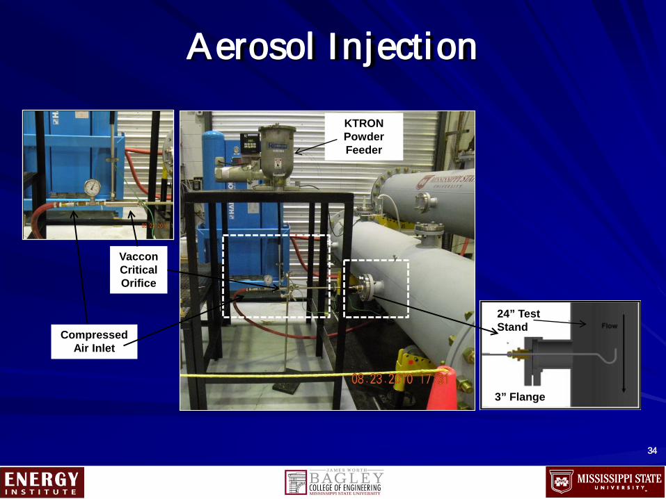
Aerosol Injection
34
24” Test Stand
Nozzle
3” Flange
Vaccon Critical Orifice
Compressed Air Inlet
KTRON Powder Feeder

Sensors
35
Relative Humidity Sensor
RH/Temp Readout
RH Probe
Pressure Sensor
Temperature Sensor
Differential Temperature
Filter Housing
Differential Pressure

36
Test Parameters and Guidelines: Aerosol #1 (Alumina)
Aerosol #2 (Carbon Black)
Aerosol #3 (AZ Road Dust)
Remote Change Dimple Pleat Filter
Test Set 1: 56.6 m3/min (2000 SCFM) 15.6 to 26.7 (60 and 80) 40-60% RH Max dP and/or failure
2 Filters 2 Filters 2 Filters
Safe Change Dimple Pleat Filter
1 Filter 1 Filter 1 Filter
Ribbon Separator Filter
1 Filter N/A N/A
Remote Change Dimple Pleat Filter
Test Set 2: 56.6 m3/min (2000 SCFM) 54.4ºC (130ºF ) 95-100% RH Max dP and/or failure
2 Filters N/A N/A
Safe Change Dimple Pleat Filter
1 Filter N/A N/A
Ribbon Separator Filter
1 Filter N/A N/A

Burner Characterization
37
0
200000
400000
600000
800000
1000000
1200000
1400000
0 0.05 0.1 0.15 0.2 0.25 0.3
dN/d
log
dp (#
/cc)
Particle Diameter (µm)
Alumina Baseline Particle Size Distribution
Burner Characterization
38
0
100
200
300
400
500
600
0 10 20 30 40 50 60 70
CO
Em
issi
ons (
PPM
)
Primary Air Controller Set Point
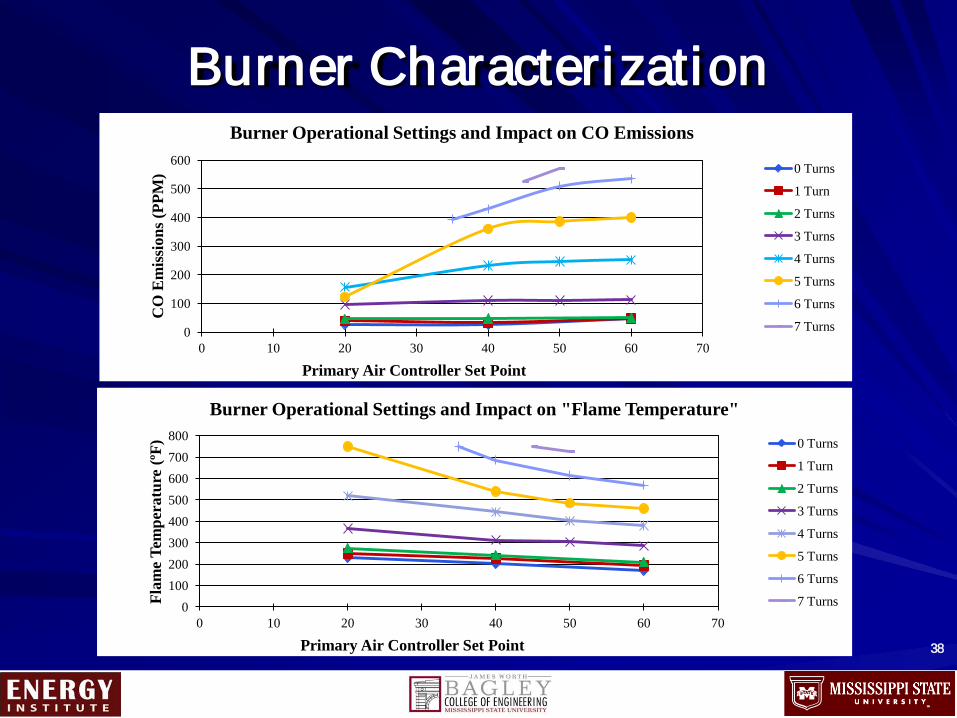
Burner Operational Settings and Impact on CO Emissions
0 Turns
1 Turn
2 Turns
3 Turns
4 Turns
5 Turns
6 Turns
7 Turns
0 100 200 300 400 500 600 700 800
0 10 20 30 40 50 60 70
Flam
e Te
mpe
ratu
re (º
F)
Primary Air Controller Set Point
Burner Operational Settings and Impact on "Flame Temperature"
0 Turns
1 Turn
2 Turns
3 Turns
4 Turns
5 Turns
6 Turns
7 Turns

Burner Aerosol Resolution
39
1
10
100
1000
10000
100000
1000000
10000000
0 100 200 300 400 500 600 700 800 900 1000
Part
icle
Con
cent
ratio
n (#
/cc)
dN
/dlo
gdp
Particle Diameter (nm)
Burner, Alumina, and Ambient Air PSD
Burner Startup PSD Alumina PSD Ambient Air PSD Burner Warmed Up PSD

Elevated Flow Examination Pi tot Traverses
40
35
45
55
65
75
85
0.00 0.20 0.40 0.60
Volu
met
ric
Flow
rate
(m3 /m
in)
Distance (m) from Back Wall
Horizontal Traverse
No Straightener Center With Straightener With Straightener and Burner
0.00
0.10
0.20
0.30
0.40
0.50
0.60
35 45 55 65 75 85
Dis
tanc
e (m
) fro
m B
otto
m W
all
Volumetric Flowrate (m3/min)
Vertical Traverse
No Straightener
Center
With Straightener
With Straightener and Burner

Elevated Flow Examination
41
40
60
80
100
0
0.2
0.4
0.6
0.8
1
1.2
1.4
1.6
1.8
14:38:24 15:07:12 15:36:00 16:04:48
Volu
met
ric
Flow
rate
(Std
m3/
min
)
Diff
eren
tial P
ress
ure
(kPa
)
Time
Safe Change Filter Test (Preloaded with Alumina to 1 kPa) Operated at Elevated ACFM flowrates
to mimic SCFM at elevated T
Differential Pressure (KPa) Volumetric Flowrate (Std m^3/min)
65 m^3/min 68 m^3/min
71 m^3/min 57 m^3/min

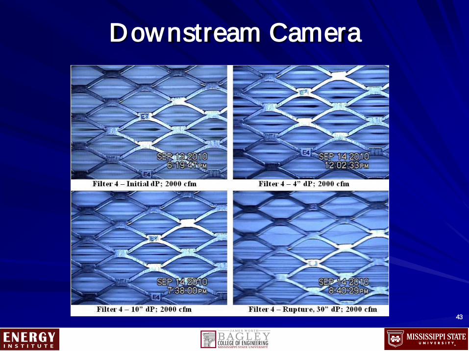
Downstream Camera
42
Digital Camera
Test Filter
Camera Pan and Tilt Head
LED Ring Light
Downstream Camera
43

Upstream Camera
44
Digital Camera
Swivel Mechanism
LED Lamps
A B
C D

M ass Loading Curves – Al l Fi l ters
45
0
2
4
6
8
10
12
0 1000 2000 3000 4000 5000 6000 7000 8000
Diff
eren
tial P
ress
ure
(KPa
)
Mass (grams)
Mass Loading Curves All Flters
Safe Change - Carbon Black
Safe Change - Carbon Black
Remote Change - Carbon Black
Remote Change - Carbon Black
Remote Change - AZ Road Dust
Remote Change - AZ Road Dust
Safe Change - AZ Road Dust
Remote Change - Alumina
Safe Change - Alumina
Remote Change - Alumina

First Test Fi l ter Safe Change
46

Test Stand Characterization
Burner Characterization Burner Aerosol Resolution Elevated Flow Examination – Traverses (Compare w/ Previous)
Elevated Temperature Examination – Issue wi th operational f low
47

Elevated Temperature Examination
48
0
10
20
30
40
50
60
70
80
0
2
4
6
8
10
12
14
16
18
20
14:38:24 14:52:48 15:07:12 15:21:36 15:36:00 15:50:24 16:04:48 16:19:12 16:33:36
Volu
met
ric
Flow
rate
(m3/
min
)
Diff
eren
tial P
ress
ure (
kPa)
Time
Filter Preloaded to 1 KPa with Alumina Tested at 56.6 m3/min Actual Flow with Elevated Temperature
Differential Pressure Volumetric Flowrate (Std m^3/min) Volumetric Flowrate (Actual m^3/min)
56.6 m3/min @ 540C
Add RH @ 50%
Burner & Water Spray OFF