performance comparison of dimple pleat and ribbon ...performance comparison of dimple pleat and...
TRANSCRIPT

32nd NACC, June 17-19, 2012, Denver, CO
1
International Society for Nuclear Air Treatment Technologies 32nd Nuclear Air Cleaning Conference June 17-19, 2012 Denver, CO
Performance Comparison of Dimple Pleat and Ribbon Separated Radial Flow HEPA Filters.
Paxton K. Giffin, Michael S. Parsons, John. A. Wilson, Charles A. Waggoner Institute for Clean Energy Technology, Mississippi State University
205 Research Blvd Starkville, MS 39759 ABSTRACT High Efficiency Particulate Air (HEPA) filters are the filters of choice for containment ventilation systems. Facilities within the US Department of Energy (DOE) complex are likely to use HEPA filters in processing exhaust gases prior to release to the environment. ICET has developed a large-scale HEPA filter test stand capable of evaluating the performance of one or two 56.63 m3/min (2000 CFM) radial flow filters at rated flow and differential pressure levels up to 12.5 kPa (50 in. w.c). This test stand has most recently been utilized to conduct testing of both dimple pleat and ribbon separated radial flow HEPA filters. Testing of the dimple pleat separated filters consisted of performance evaluation of both a safe and remote change version at ambient conditions, 15.6 to 26.7ºC (70 to 80ºF) and 40-60% RH, and elevated conditions, at 54.4ºC (130ºF) and 50%+ RH. Testing of the ribbon separated radial flow units consisted of evaluating only one design under ambient and elevated conditions. Results from these testing activities include comparisons of the total mass loading, filtering efficiency performance, and performance under elevated conditions of temperature and relative humidity.
INTRODUCTION Processes involving management or treatment of radioactive materials typically require the use of high efficiency particulate air (HEPA) filters in containment ventilation systems. Facilities within the US Department of Energy (DOE) complex use HEPA filters to process exhaust gases before they enter the environment because of their low particle penetration.
Radial Flow HEPA Filter for Nuclear Applications The DOE Nuclear Air Cleaning Handbook1 designates that all air filtration systems for waste treatment facilities must comply with the American Society of Mechanical Engineers (ASME) Code on Nuclear Air and Gas Treatment (AG-1)2. This standard is comprised of multiple sections depicting design and testing criteria for air and gas treatment for nuclear applications. The AG-1 standard indicates very specific qualification procedures. For a filter to be used for nuclear air cleaning it must be qualified and pass certification at a filter test facility (FTF). These qualification procedures include resistance to airflow, aerosol penetration, resistance to rough handling, resistance to pressure, resistance to heated air, spot flame test, and structural requirement inspection. More on the qualification procedures can be found in the AG-1 standard2.

32nd NACC, June 17-19, 2012, Denver, CO
2
The primary filter of choice within the DOE complex has historically been the AG-1 Section FC axial flow unit. The most common FC filter is the square, deep pleated, axial flow filter with metal separators. These axial flow filters provide good filtering efficiencies and dust loading capacities, but they present other issues with handling and disposal. Radial units provide benefits in remote handling, ease of sealing, disposal, compaction, reduction in sharp edges, and retention of particulates during handling3. Radial flow filters have been studied in the United Kingdom3,4,5. Section FK was added to AG-1 to address special types of HEPA filters. One of the special HEPA filters discussed in FK was the radial flow circular filter. Some European loading data for these types of filters are available5. In May of 1999 the Defense Nuclear Facilities Safety Board (DNFSB) released Technical Report 23 entitled HEPA Filters Used in the Department of Energy’s Hazardous Facilities6. This report expressed concerns for the potential vulnerability of HEPA filters used in vital safety systems. One problem addressed in this document was that every filter used was not tested at an FTF to ensure it met specifications. The other main points addressed in this document were the need for a Qualified Products List (QPL) test laboratory the problems associated with filter wetting, issues with filter aging, radiation induced degradation, by-pass leakage consideration, and the issues associated with the HEPA filter infrastructure. Later that same year, the DOE initiated a response to the DNFSB’s Recommendation 2000-27 by implementing measures with regard to 100 percent quality assurance testing of HEPA filters and a review of vital safety systems in general8 DOE’s actions also came at a time when concerns were being voiced by citizen groups over the performance of HEPA filters and how the functional status of a filter is monitored.. DOE Standard 10669 titled “Fire protection Design Criteria” explains the measures and considerations to limit or prevent damage due to fire and smoke. Upset conditions, such as those during a fire, need to be evaluated and the performance of the HEPA filter quantified under those conditions.
Dimple Pleat Testing Testing on dimple pleat HEPA filters was performed at the Energy Institute at Mississippi State University (MSU) from 2010 to 2011. The goal was to evaluate lifetime performance of these HEPA filters under ambient and elevated conditions. These filters are only representative AG-1 units as there are currently no existing qualified FK radial flow filters. This document will examine both remote change and safe change designs. These designs will be evaluated under both ambient and elevated conditions of relative humidity and temperature. Nine filters were evaluated at ambient conditions. Three filters are challenged by each of three aerosols. Ambient conditions fall between 15.6 to 26.7 (60 and 80 ) and 40 to 60 % relative humidity (RH). These filters are loaded with aerosol until the filter reaches 12.5 kPa (50 in. w.c.) or ruptures. Results of the ambient condition testing have been previously discussed at a conference10. Elevated condition testing consisted of three filters challenged with an aerosol up to 1 kPa (4 in. w.c) of differential pressure across the filter under ambient conditions. The aerosol challenge was then discontinued and the performance of the filter is examined under elevated temperature, 54.4ºC (130ºF), for a period of one hour. Water spray was next added to incrementally increase the relative humidity to 95%+. Results from the elevated condition testing have also been discussed at a conference11. Ribbon Separated Filter Testing Ribbon separated radial flow HEPA filters were evaluated in the early part of 2012. Testing activities included evaluation of one filter under ambient conditions and two filters under elevated conditions. The conditions of these tests were the same as the dimple pleated filters

32nd NACC, June 17-19, 2012, Denver, CO
3
but only one challenge aerosol, Alumina (Spacerite S-11), was used for the entirety of the ribbon separated filter evaluations. TEST STAND The test stand utilizes a fan that is capable of producing differential pressures of 12.45 kPa (50 in. w.c.) at volumetric air flow rates of 113.3 m3/min (4000 CFM). The housing is capable of testing two filters at 113.3 m3/min (4000 CFM) or one filter at 56.63 m3/min (2000 CFM). Only one filter at a time is currently being tested with a blind taking the place of the other filter in the housing. A schematic of the test stand is presented in Figure 1, with Table 1 indicating the associating components. Images of the indoor and outdoor portions of the test stand are presented in Figures 2 and 3, respectively.
Fig. 1. Schematic of the large-scale HEPA test stand.
Table I. Large-Scale Test Sand Components Component
Number Component
1 Induced Draft Fan 2 Venturi Flow Meter 3 Radial Flow Housing 4 Aerosol Neutralization Section 5 Aerosol Sampling Locations 6 Powder Feeder 7 Flow Straightener (In Duct) 8 Water Nozzles 9 Air Intake
10 Natural Gas Burner

32nd NACC, June 17-19, 2012, Denver, CO
4
Fig. 2. Image of the indoor portion of the test stand.
Fig. 3. Image of the outdoor portion of the test stand.

32nd NACC, June 17-19, 2012, Denver, CO
5
TESTING PARAMETERS Ambient Condition Testing Parameters Both the dimple pleated and ribbon separated filter types were tested at 56.63 m3/min (2000 CFM) under ambient conditions. More dimple pleated filters tested at ambient conditions than ribbon separated filter, as displayed in the testing matrix presented in Table II. There was only one test performed for the ribbon separated filter design. That filter was challenged with Alumina. Table II. Ambient Condition Testing Matrix
Test Parameters and Guidelines: Aerosol #1 (Alumina)
Aerosol #2 (Carbon Black)
Aerosol #3 (AZ Road Dust)
Remote Change Dimple Pleat Filter
Test Set 1: 56.6 m3/min (2000 SCFM) 15.6 to 26.7 (60 and 80 ) 40-60% RH Max dP and/or failure
RC-DS1-001 RC-DS1-002 RC-DS1-003
Safe Change Dimple Pleat Filter
SC-DS1-001 SC-DS1-002 SC-DS1-003
Remote Change Dimple Pleat Filter
RC-DS2-007 RC-DS2-008 RC-DS2-009
Ribbon Separated Filter
VT-004 N/A N/A
Elevated Condition Testing Parameters The elevated conditions testing activities was performed in two phases. The initial phase was to the load the filter with Alumina to its change-out differential pressure of 1 kPa (4 in. w.c.). The second phase was to evaluate the filter performance without a challenge aerosol at elevated temperature of 54.4ºC (130ºF) for one hour. Next the relative humidity was incrementally increased up to 95%. Three dimple pleated filters and two ribbon separated filters were tested under elevated conditions as displayed in Table III.

32nd NACC, June 17-19, 2012, Denver, CO
6
Table III. Dimple Pleated Filters Elevated Condition Testing Matrix
Test Parameters and Guidelines: Aerosol #1 (Alumina)
Remote Change Dimple Pleat Filter
Test Set 2: 56.6 m3/min (2000 SCFM) 54.4ºC (130ºF ) 95-100% RH Max dP and/or failure
RC-DS1-004
Safe Change Dimple Pleat Filter
SC-DS1-004
Remote Change Dimple Pleat Filter
RC-DS2-010
Ribbon Separated Filter
VT-001
Ribbon Separated Filter
VT-002
Filter Designs
The remote and safe change filter designs are tested using dimple pleated separators. Both designs are manufactured by Flanders Filters Inc. (Washington, NC). Figure 4 displays the dimple pleat separated filter designs. Modifications were made to the filters and housing to accommodate both filter designs. The two filter designs differ in the location of sealing surface. Remote change radial flow filters are designed to be remotely installed into a housing vertically using a crane. This remote installation is facilitated by a grab ring located around the circumference of the filter annulus and a gel seal gasket on the underside of the filter end cap. The safe change radial flow filter is designed for bag-in/bag-out horizontal installation into its housing. The safe change also utilizes a gel seal, however the sealing surface is located on the face of the filter end cap. Table IV displays the filter pack design parameters. The rated flow for both designs is 56.63m3/min (2000 CFM).
Fig. 4. Photographs of (A,B) safe change and (C,D) remote change filters.
Table IV. Filter Pack Design Parameters for the Safe Change and Remote Change Filter Types.
Filter Type Safe Change Remote Change
Number of Pleats 345 330
Media (m2) 29.73 29.17
Interior Diameter (cm) 33.02 27.94

32nd NACC, June 17-19, 2012, Denver, CO
7
The large-scale HEPA test stand utilizes a safe change radial flow filter housing. Testing of remote change filters required a modification to the safe change housing as well as two modifications to the remote change radial flow test filters. In order to accommodate the slightly longer length of the remote change design, two all-thread rods were welded to the filter installation guide bars of the housing. A metal bar is placed across the end of the filter to secure the remote change radial flow filter in the housing. The filters were modified from the gel seal to a neoprene gasket to allow for the filter initial and final mass to be obtained accurately. Only one design of ribbon separated filter is used. This filter is manufactured by Vokes Air (Burnley Lancashire, UK). This filter design has a rated flow of 56.63m3/min (2000 CFM). Figure 5 provides a diagram of the Vokes filter illustrating approximate dimensions. The primary difference in the dimple pleat and ribbon separated filters is inner diameter and the sealing mechanism. The Vokes filter design is supplied with a gasket inside the annulus of the filter. This gasket does not provide a sealing surface with the ICET radial flow filter housing. Therefore, a neoprene gasket is affixed around the annulus to provide a sealing surface which contacts the wall of the radial flow filter housing.
Fig. 5. Dimensions of ribbon separated radial flow filter.
Another difference between these the filters are their pleating mechanism. The dimple pleated filters separate the filter pack folds using embossed dimples, which are pressed onto the media. The ribbon separated filter uses a ribbon to keep the filter folds separated. An image of the ribbon separated filter media on the Vokes brand filter is displayed in Figure 6. Two images of the dimple pleated filter media on the Flanders brand filters are displayed in Figure 7.

32nd NACC, June 17-19, 2012, Denver, CO
8
Fig. 6. Image of the ribbon separated filter media.
Fig. 7. Images of the dimple pleated separated filter media.
Test Aerosols
Three different aerosols were used to represent loading by differently sized particles. The first aerosol was Carbon black (N991) manufactured by CANCARB Limited (Medicine Hat, Alberta, Canada). D. Loughborough at the Atomic Energy Authority Harwell Laboratory in the United Kingdom has conducted tests using this aerosol5. The next aerosol was Alumina, Al(OH)3, (Almatis Spacerite S-11) purchased from Brenntag Specialties, Inc. (South Planfield, NJ). This
32nd NACC, June 17-19, 2012, Denver, CO
9
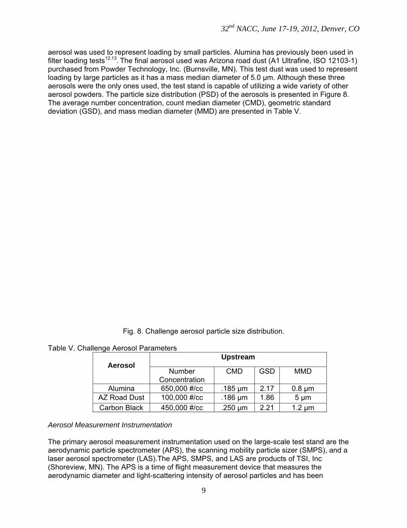
aerosol was used to represent loading by small particles. Alumina has previously been used in filter loading tests12,13. The final aerosol used was Arizona road dust (A1 Ultrafine, ISO 12103-1) purchased from Powder Technology, Inc. (Burnsville, MN). This test dust was used to represent loading by large particles as it has a mass median diameter of 5.0 µm. Although these three aerosols were the only ones used, the test stand is capable of utilizing a wide variety of other aerosol powders. The particle size distribution (PSD) of the aerosols is presented in Figure 8. The average number concentration, count median diameter (CMD), geometric standard deviation (GSD), and mass median diameter (MMD) are presented in Table V.
Fig. 8. Challenge aerosol particle size distribution.
Table V. Challenge Aerosol Parameters
Aerosol
Upstream
Number Concentration
CMD GSD MMD
Alumina 650,000 #/cc .185 μm 2.17 0.8 μm AZ Road Dust 100,000 #/cc .186 μm 1.86 5 μm Carbon Black 450,000 #/cc .250 μm 2.21 1.2 μm
Aerosol Measurement Instrumentation The primary aerosol measurement instrumentation used on the large-scale test stand are the aerodynamic particle spectrometer (APS), the scanning mobility particle sizer (SMPS), and a laser aerosol spectrometer (LAS).The APS, SMPS, and LAS are products of TSI, Inc (Shoreview, MN). The APS is a time of flight measurement device that measures the aerodynamic diameter and light-scattering intensity of aerosol particles and has been

32nd NACC, June 17-19, 2012, Denver, CO
10
extensively studied14,15. The SMPS consists of a TSI model 3080 electrostatic classifier (EC), a TSI model 3081 differential mobility analyzer (DMA), and a TSI model 3775 condensation particle counter (CPC). The SMPS sizes the particles according to their electron mobility then counts them with the CPC. The LAS operates based on the principle that the degree of light scattering is dependent on the size of the aerosol particle. More information on these instruments is available16. Table VI presents the concentration and size capabilities for these instruments. Table VI. Size and Concentration Capacity for Aerosol Measuring Instruments Instrument #/cc (min) #/cc (max) PSD (µm) TSI SMPS with Model 3775 CPC 1 1x10⁷ 0.004 - 3 TSI Model 3321 APS 1 1x10³ 0.5 - 20 TSI Model 3340 LAS <0.02 1.8x10⁴ 0.09 - 7.5
RESULTS Ambient Condition Testing Results For the ambient conditions results, we are primarily concerned with loading capacity and filtering efficiency performance. A total of 12 dimple pleat filters were tested with three challenge aerosols. Three ribbon separated filters were tested. The only ribbon separated filter challenged to a high differential pressure was damaged during shipping. Due to this damage, the filter leaked. Because of the leak, the only useful results that could be obtained were to examine the differential pressure curve and mass loading curve. The remaining ambient condition results were obtained by one of the ribbon separated filter used for the elevated condition testing during the portion of that test in which the filter was loaded to 1 kPa (4 in. w.c.). Differential Pressure vs. Time Comparison During the testing of the dimple pleat filters, it was observed that after the differential pressure across the filter rose to around 2 kPa (8 in. w.c.), the curve transitioned from linear to exponential. After observing this phenomenon, it was critical to determine the characteristics of the slope of differential pressure increase for the ribbon separated filter design. It was thought that the minor shipping damage would have little effect on this parameter. The filter still maintained a nominal filtering efficiency greater than 99.8%. Figure 9 compares the differential pressure versus time for the three dimple pleat filters to the ribbon separated filter tested loaded with alumina. All three mass loading rates were similar for all four tests. In Figure 9 The most significant difference between the different filters is the slope of the curves. The ribbon separated filter appears to load more quickly initially, yet they remain much more linear over the entire test. The overall loading time appears to be similar between all filters tested. Typically, for the ambient condition test, the filter is considered to have failed when the filtering efficiency drops below HEPA requirements. Further testing should be completed to determine at what point a filter would have ‘failed’ because the test filter was initially below HEPA efficiency before the test had begun.

32nd NACC, June 17-19, 2012, Denver, CO
11
Fig. 9. Differential pressure versus time comparison for all filters tested under ambient
conditions with Alumina as the challenge aerosol. Mass Loading Curve Comparison The mass loading curves display the mass loading (grams) versus differential pressure across the filter. Figure 10 illustrates the mass loading for all nine dimple pleat filters challenged at ambient conditions. This plot indicates a change in slope as the filters load. The effects of changes in the PSD of the aerosol challenge are also apparent in the total mass loading. It is evident that an increase in the MMD of the challenge aerosol will lead to an increase in the total mass loading on the filter. Figure 10 displays the effect of the PSD on the total mass loading.
. Fig. 10. Mass loading curves for all dimple pleated filters.

32nd NACC, June 17-19, 2012, Denver, CO
12
A useful comparison of the mass loading curves of the dimple pleat filters challenged with Alumina to the ribbon separated filter is displayed in Figure 11. While the loading times may have been similar in Figure 9, the total mass loaded was much different. The ribbon separated filter loaded almost double the mass as the dimple pleat filter. Figure 11 also indicates that the safe change dimple pleat filter cannot hold as much particulate matter as the remote change dimple pleat filter, while the ribbon separated filter can hold the most particulate matter.
Fig. 11. Mass loading curve comparison of dimple pleat and ribbon separated filters.
Filtering Efficiency Performance Comparison Another important aspect of filter performance is filtering efficiency. HEPA filters are required to be at least 99.97% efficient at removing particulate matter 0.3 µm and larger from an airstream. One of the ribbon separated filters used for the elevated condition testing is used for the remaining ambient condition testing results. This is because the ribbon separated filter used thus far was damaged during shipping and had some minor tears in the media. The next two result comparisons use the ambient loading portion, up to 1 kPa (4 in. w.c.), of the elevated test on one of the ribbon separated filters. Figure 12 displays the filtering efficiency and downstream aerosol concentration for three test filters. The three filters are (A) a dimple pleat filter challenged with alumina, (B) an undamaged ribbon separated filter, and (C) the damaged ribbon separated filter. The filtering efficiency reported here is for all particle sizes measuring approximately 0.09 to 7.5 nm. For (A) and (B) in Figure 12, the downstream concentration rapidly decreased to zero particles. This drop in downstream particle counts led to the filtering efficiency rapidly becoming 100%. This drop indicates that there are very few to zero particles downstream once the filter loads a small amount of material. Figure 12 (C) displays the filtering efficiency and downstream concentration for the filter that was damaged during shipping. Figure 12 (C) indicates that the total filtering efficiency is less

32nd NACC, June 17-19, 2012, Denver, CO
13
than HEPA requirements. An important aspect that can be observed in Figure 12 (C) is the rupture of the filter. This rupture appears to be rather gradual, which contrasts with Figure 12 (A) where the filter held at virtually 100% and then ruptured rather catastrophically. The full extent of the dimple pleat filter rupture is not presented here because the particle concentrations exceeded the range of operation for the sampling instrument used for that test. Note that the filter in Figure 12 (C) was damaged during shipping and to fully map the rupture of a ribbon separated filter.
Fig. 12. Filtering efficiency and downstream concentration versus time for (A) dimple pleat separated filter, (B) undamaged ribbon separated filter, and (C) damaged ribbon separated
filter.

32nd NACC, June 17-19, 2012, Denver, CO
14
Penetration Curves The penetration curve or filtering efficiency versus particle diameter is a direct comparison of the upstream particle size distribution and downstream particle size distribution to see how well the filter performs at filtering differently sized particles. The penetration curve is also useful in locating the most penetrating particle size. Figure 13 displays the penetration curves for (A) a dimple pleat separated filter and (B) a ribbon separated filter. In both filters, two different samples for these data are presented. The samples were taken at the beginning of the test and again at 1 kPa (4 in. w.c.). For the initial conditions sample, most particles measured are 500 nm and smaller. The ribbon separated filter is more efficient than the dimple pleat separated filter at this sample. Both filters have virtually no particles downstream as the filter reaches 1 kPa (4 in. w.c.) in differential pressure across the filter.

32nd NACC, June 17-19, 2012, Denver, CO
15
Fig. 13. Penetration curves for (A) dimple pleat separated and (B) ribbon separated filters. Filter In-Testing Images The test stand has been equipped with a camera in the filter housing to observe changes in the filter pack during loading. Time-stamped, digital images of filter pack exterior are collected during testing at specific differential pressure intervals. Digital images collected during testing provide important data related to the filter pack during loading. The photo is taken at the area postulated to undergo the highest amount of stress and thus deemed most likely to fail. This location was determined to be near the seam in the filter media. Figure 14 depicts the region on the backside of the filter the camera is focused on.

32nd NACC, June 17-19, 2012, Denver, CO
16
Fig. 14. In-testing camera focus region.
Figure 15 displays the filter pack of a dimple pleat filter challenged at ambient conditions with alumina until filter rupture. The differential pressure intervals for the images are 1 kPa (4 in. w.c.), 2.5 kPa (10 in. w.c.), 5 kPa (20 in. w.c.) and filter failure, which for the test filter was 7.2 kPa (29 in. w.c.) In Figure 15 (A), the gap between the filter media to allow for maximum filter surface area can be seen. Figures 15 (B) and (C) illustrate how these gaps are starting to close, and (D) features how the pleats have collapsed, leading to failure.
Fig. 15. In-testing images at (A) 1 kPa (4 in. w.c.), (B) 2.5 kPa (10 in. w.c.), (C) 5 kPa (20 in.
w.c.), D:7.2 kPa (29 in. w.c.). Figure 16 displays images of a ribbon separated filter at different times during testing at ambient and elevated conditions. Figure 16 was captured at (A) initial conditions, (B) 1 kPa (4 in. w.c.), and images (C) and (D) were obtained in the elevated portion of the test. Figure 16 illustrates that there is little to no collapse of the interstitial spaces between the filter folds. This result is contrary to the observation in Figure 15. Based on this result, the ribbon separated design appears to be a more robust filter in the aspect of filter media pack rigidly.

32nd NACC, June 17-19, 2012, Denver, CO
17
Fig. 16. In-testing images at different levels of differential pressure for the ribbon separated
filter. Elevated Temperature Results Dimple Pleat Separated For the elevated condition results the testing parameters: differential pressure, temperature, and relative humidity versus time are reported. These parameters are examined only for the portion of the test at which the filter is being challenged with elevated conditions of temperature and relative humidity.This testing portion is after the filters have already been loaded to 1 kPa (4 in. w.c.) under ambient conditions. The test was conducted by initially challenging the filter to elevated temperature at 60ºC (130ºF) for one hour. Following this hour, the relative humidity was incrementally increased by 25% increments to a maximum of 95%+. Figure 17 displays the three dimple pleated separated filters evaluated at elevated conditions. The two remote change dimple pleated filters performed very similarly to each other. Only after the relative humidity reached around 80% did the filters fail. The safe change dimple pleated filter ruptured during the elevated temperature, first phase, of testing. This test confirms that the safe change filter design is inferior to the remote change design in dry mass loading and resistance to elevated conditions.

32nd NACC, June 17-19, 2012, Denver, CO
18
Fig. 17. Differential pressure, humidity, and temperature versus time for the first remote change
filter challenged at elevated levels of temperature and relative humidity.

32nd NACC, June 17-19, 2012, Denver, CO
19
Ribbon Separated Filters The testing on the ribbon separated filters was performed identically to the elevated condition testing on the dimple pleated filters. Figure 18 displays the two ribbon separated radial flow filter tests. Unlike the dimple pleated filters, both ribbon separated filters endured this test. The first test filter was removed from the housing after the test, dried in an oven overnight, and had its filtering efficiency reevaluated. The filter was still HEPA efficient. Following the test on the second ribbon separated filter, that filter was subjected to a 2.27 L/min (.5 GPM) water sprayed directly into the annulus of the filter. After a short period of time, this water spray drove the filter to failure.

32nd NACC, June 17-19, 2012, Denver, CO
20
Fig. 18. Differential pressure, temperature, and relative humidity versus time for the ribbon
separated filters. Post Rupture Images Important differences can be noted about the manner in which both filter types ruptured. During the ambient testing on the damaged ribbon separated filter the filter appeared to leak more and more. This result indicated that no sudden large ruptures of the media was observed as in the dimple pleat filters results. Figure 19 displays images of the rupture of dimple pleat filters. Figure

32nd NACC, June 17-19, 2012, Denver, CO
21
19 displays the catastrophic rupture induced by the collapse of the dimple pleat and ballooning of the filter pack in places. Figure 20 presents rupture images of the ribbon separated filters. These images show very different ruptures. These ruptures appear to be not as catastrophic as the ruptures observed during the dimple pleat tests. Further testing is needed to fully map the rupture mechanism of the ribbon separated filters.
Fig. 19. Post rupture images of dimple pleat filters.

32nd NACC, June 17-19, 2012, Denver, CO
22
Fig. 20. Post rupture images of ribbon separated filters.
CONCLUSIONS
A number of comparisons have been made between the dimple pleat and ribbon separated filter designs. To determine the superior design, one must examine all the aspects of a filter. Also, particular aspects may be better suited for one application over another. The important aspects for comparison are mass loading capacity, filtering efficiency performance, elevated condition performance, and filter strength. In the ambient condition evaluation of the dimple pleat filters, a significant variability in the total mass loading for the different aerosols was noticed. This observation was not possible for the ribbon separated filter due to only having one filter to test under ambient conditions. The most obvious difference in the mass loading for the ribbon and dimple pleated separator designs is the shape of the curve. The mass loading curve for the ribbon separated filter has a more consistent slope, unlike the dimple pleat filters. The test team believes that this difference in slope is due to the collapse of the dimple pleats under high levels of differential pressure that leads to the cascading effect of pleat collapse. The phenomena would lead to a reduction in free flow cross-sectional media area and a proportional increase in differential pressure. The ribbon separated design had a much larger mass loading capacity than the dimple pleat filters. Despite the fact that the differential pressure for the ribbon separated filter increases more quickly initially, it seems to be the superior filter on the basis of mass loading. The filtering efficiency of both filters passed as HEPA efficient. Comparison of the two revealed slightly better performance for the ribbon separated. There is a large difference in the manner of filter rupture. Due to the large number of dimple pleat filter tests, it was illustrated that the dimple pleat filters will maintain virtually 100% filtering efficiency up to the point of rupture. The data
32nd NACC, June 17-19, 2012, Denver, CO
23
suggest that the ribbon separated filters does not performs in this manner. T ribbon separated filter begins to leak more and more as small ruptures appear with the increase in differential pressure. The leaks start developing around 2.5 kPa (10 in. w.c.). To confirm the result for the ambient condition ribbon separated filter, more tests are required. Depending on the application, one filter design or the other might be better suited for use. Testing revealed major differences in the performance of the two filter types under elevated conditions. In every remote change dimple pleat filter design test, the filter only began to fail after the water spray was initiated to elevate the relative humidity of the airstream. The remote change filters typically failed after a relative humidity greater than 80%. This failure is believed to be caused in part by the dimple pleats of the media. As the pleats absorb moisture, they begin to lose their rigidity, leading to a failure to keep the media folds separated. The safe change dimple pleat filter test failed before water was even introduced into the airstream. The ribbon separated filters passed both elevated temperature and relative humidity testing. The filter only failed after it was subjected to water sprayed directly into the annulus of the filter. The final point of comparison examines the strength of the filters. This comparison is based on how robust the filter is structurally and the resistance of the media to elevated conditions. The ribbon separated filter seems to be less robust than the dimple pleat design. This comparison was a general observation, yet an example of this is the expanded metal grille on the outside is of a thinner gauge than the dimple pleat filter. The resistance to elevated conditions has already been discussed, resulting in the ribbon separated filters determined as displaying superior performance. The results indicate that there are issues with the dimple pleat design. Due to the pleat collapse phenomena, these filters do not perform as well as the ribbon separated filter design. It is uncertain if the separators are the only reason that the dimple pleat filters do not perform well at elevated conditions. Aside from this issue, the dimple pleat filters seem to be better constructed and more efficient at higher levels of differential pressure. Again, only one ribbon separated filter was tested for mass loading and it was damaged during shipping. The test team plans to secure additional funding to evaluate more ribbon separated filters at ambient conditions with a variety of aerosols to accurately map that filter’s performance. PROJECT TEAM The Institute for Clean Energy Technology (ICET) at Mississippi State University (MSU) was established in 1979 to support the Department of Energy’s (DOE) Magnetohydrodynamic (MHD) power program. From its inception, the mission of ICET has been to develop advanced instrumentation, and use that instrumentation to characterize processes and equipment. ICET’s testing capability and its ability to rapidly deploy very sophisticated instrumentation in the field have been important components of its success. ICET has recently become part of the newly formed Energy Institute at MSU.
ICET has a multidisciplinary staff of 20 full-time employees that include chemists, physicists, computer scientists, and chemical, electrical, and mechanical engineers. ICET scientists have leading-edge expertise in the application of lasers to energy and environmental cleanup. ICET’s staff is a unique blend of measurement specialists, control specialists, and an experienced engineering and operations staff, primed to carry out its mission. ICET also employs graduate and undergraduate students who further support research operations. ICET also employs a Certified Industrial Hygienist (CIH) and a Certified Hazardous Materials Manager (CHMM).

32nd NACC, June 17-19, 2012, Denver, CO
24
These individuals ensure all activities conducted by ICET adhere to applicable environmental, safety and health practices. ACKNOWLEDGEMENTS
We acknowledge the support of this work under DOE Cooperative Agreement DE-FC01-06EW07040. REFERENCES 1U.S. Department of Energy (DOE): Nuclear Air Cleaning Handbook (DOE-HDBK-1169-2003), DOE Handbook, (2003).
2American Society of Mechanical Engineers (ASME): Code on Nuclear Air and Gas Treatment (ASME AG-1) [Standard]. New York: ASME, (2009).
3B.L. Steward. “Development and Applications of Circular Filter Inserts.” ASHRAE Transactions, pp.908-919. NT-87-01-4, (1987).
4W. Kuile and R. Doig. "Circular HEPA Filters for use in Nuclear Containment and Ventilation Systems." 25th Nuclear Air Cleaning Conference, (1998).
5D. Loughborough. "The Dust Holding Capacity of HEPA Filters." 21st Nuclear Air Cleaning Conference (1990).
6 “HEPA Filters Used in the Department of Energy’s Hazardous Facilities”; Defense Nuclear Facilities Safety Board; DNFSB/TECH-23, May (1999).
7 http://www.dnfsb.gov/pub_docs/recommendations/all/rec_2000_02.pdf
8D. Cragin et al, “Application of ASME AG-1 to the DOE Hanford Tank Waste Treatment and Immobilization Plant,” 28th Nuclear Air Cleaning and Treatment Conference, (2004).
9U.S. Department of Energy (DOE): Fire Protection Design Criteria (DOE-STD-1066-99), DOE Standard, (1999).
10Paxton K. Giffin, Michael S. Parsons, Jaime G. Rickert, and Charles A. Waggoner. “Results from Evaluation of ASME AG-1 Section FK Radial Flow HEPA Filters - 11287”; Waste Management ’11, February 27 - March 3, 2011, Phoenix, AZ (2011). 11Paxton K. Giffin, Michael S. Parsons, Jaime G. Rickert, and Charles A. Waggoner. “Results from Evaluation of ASME AG-1 Section FK Radial Flow Dimple Pleated HEPA Filters Under Elevated Conditions - 12002”; Waste Management ’12, February 26 - March 1, 2012, Phoenix, AZ (2012). 12 K.W. Lee and B.Y.H. Liu. "Experimental Study of Aerosol Filtration by Fibrous Filters." Aerosol Science and Technology, 1: 35-46 (1982).
13 Y. Endo, Da-Ren Chen, David Y.H. Pui. "Bimodal Aerosol Loading and Dust Cake Formation on Air Filters." Filtration & Separation, pp. 191-195, March (1998).

32nd NACC, June 17-19, 2012, Denver, CO
25
14 B.T. Chen et.al. “Performance of a TSI Aerodynamic Particle Sizer.” Aerosol Science and Technology, 4: 89-97 (1985).
15 T.M. Peters et.al. “Comparison and Combination of Aerosol Size Distributions Measured with a Low Pressure Impactor, Differential Mobility Particle Sizer, Electrical Aerosol Analyzer, and Aerodynamic Particle Sizer.” Aerosol Science and Technology, 19:396-405. (1993).
16 P.A. Baron and K. Willeke. Aerosol Measurement: Principles, Techniques, and Applications. Wiley and Sons, 2nd Ed. (2005).