performance and design optimization of a low-cost solar...
TRANSCRIPT
Available online at www.sciencedirect.com
www.elsevier.com/locate/solener
Solar Energy 85 (2011) 955–966
Performance and design optimization of a low-cost solarorganic Rankine cycle for remote power generation
S. Quoilin a,⇑, M. Orosz b, H. Hemond b, V. Lemort a
a Thermodynamics Laboratory, University of Liege, Campus du Sart Tilman, B49, B-4000 Liege, Belgiumb Department of Civil and Environmental Engineering, Massachusetts Institute of Technology (MIT), 15 Vassar St. 48-216, Cambridge, MA 02139, USA
Received 7 December 2010; received in revised form 10 February 2011; accepted 15 February 2011Available online 16 March 2011
Communicated by: Associate Editor R. Petela
Abstract
Recent interest in small-scale solar thermal combined heat and power (CHP) power systems has coincided with demand growth fordistributed electricity supplies in areas poorly served by centralized power stations. One potential technical approach to meeting thisdemand is the parabolic trough solar thermal collector coupled with an organic Rankine cycle (ORC) heat engine.
The paper describes the design of a solar organic Rankine cycle being installed in Lesotho for rural electrification purpose. The systemconsists of parabolic though collectors, a storages tank, and a small-scale ORC engine using scroll expanders.
A model of each component is developed taking into account the main physical and mechanical phenomena occurring in the cycle andbased on experimental data for the main key components.
The model allows sizing the different components of the cycle and evaluates the performance of the system. Different working fluidsare compared, and two different expansion machine configurations are simulated (single and double stage).� 2011 Elsevier Ltd. All rights reserved.
Keywords: Organic Rankine cycle; ORC; Solar concentrator; Parabolic trough; Rural electrification; Concentrating solar power
1. Introduction
Concentrating Solar Power (CSP) systems have beenimplemented with a variety of collector systems such as theparabolic trough, the solar dish, the solar tower or the Fres-nel linear collector. However, most of the currently installedCSP plants use a steam Rankine cycle in the power block.This technology requires a minimum power of a few MWein order to be competitive and involves high collectortemperatures.
Particularly in the case of small-scale systems, an organicRankine cycle (i.e. a Rankine cycle using an organic fluidinstead of water) may show a number of advantages overthe steam cycle. These include a lower working temperature,
0038-092X/$ - see front matter � 2011 Elsevier Ltd. All rights reserved.
doi:10.1016/j.solener.2011.02.010
⇑ Corresponding author. Tel.: +1 32 4 366 48 22; fax: +1 32 4 366 48 12.E-mail address: [email protected] (S. Quoilin).
the absence of droplets during the expansion, the low main-tenance requirements and the simplicity (fewer compo-nents). According to McMahan (2006), those advantagesmake the ORC technology more economically attractivewhen used at small and medium power scales.
Solar ORCs have been studied both theoretically(Davidson, 1977; Probert et al., 1983) and experimentally(Monahan, 1976) as early as in the 1970s and with reportedoverall efficiencies varying between 2.52% and 7%. Experi-mental studies usually involved the use of vane expanders(Badr et al., 1985 multi-vane expanders, Davidson, 1977),and high Ozone Depleting Potential (ODP) refrigerantssuch as R11 or R13 were often used. Recent studies havetended to emphasize optimization of fluid selection fordifferent cycle architectures and collecting temperatures(Wolpert and Riffat, 1996; McMahan, 2006; Delgado-Torres and Garcia-Rodriguez, 2007, 2010; Bruno et al.,
Nomenclature
A area, m2
c specific heat, J/(kg K)D diameter (m)
FF filling factor, –h heat transfer coefficient, W/(m2 K)h specific enthalpy, J/(kg K)k conductivity, W/m KL length, mM mass, kgM mass flow rate, kg/sn number of nodesNp number of platesNrot rotating speed, rpmp pressure, Papinch pinch point value, KQ heat power, Wq linear heat flux, W/mr ratio, –rv,in Internal built-in volume ratio, –Sbeam beam solar insolation, W/m2
T temperature, �CU heat transfer coefficient, W/(m2 K)v specific volume, m3/kgV velocity, m/sVs swept volume, m3
V volume flow rate, m3/sw specific work, J/kgW width, m
Greek symbols
a absorptivity
e effectivenesse emissivityg efficiencyq density, kg/m3
q reflectivity, –s transmittance –
Subscripts and superscripts
abs absorberamb ambientcd condensercol collectoreV evaporatorex exhaustexp expanderi relative to cell i
htf heat transfer fluidhx heat exchangerl liquidopt opticalp pressurepp pumprec recuperatorsu supplysf secondary fluidtp two-phasetot totalv vaporv volume
956 S. Quoilin et al. / Solar Energy 85 (2011) 955–966
2008; Wang et al., 2010a). It is interesting to note, however,that no single fluid has been identified as optimal for theORC. This is mainly due to the strong interdependencebetween the optimal working fluid, the working conditionsand the cycle architecture. It follows that the study of theworking fluid candidates should be integrated into thedesign process of any ORC system.
Few studies have provided experimental data from oper-ational solar ORC systems: Kane et al. (2003) studied thecoupling of linear Fresnel collectors with a cascaded 9-kWe ORC, using R123 and R134a as working fluids. Anoverall efficiency (solar to electricity) of 7.74% wasobtained, with a collector efficiency of 57%. Manolakoset al. (2007) studied a 2 kWe low-temperature solar ORCwith R134a as working fluid and evacuated tube collectors:an overall efficiency below 4% was obtained. Wang et al.(2010b) studied a 1.6 kWe solar ORC using a rolling pistonexpander. An overall efficiency of 4.2% was obtained withevacuated tube collectors and 3.2% with flat-plate collec-tors. The difference in terms of efficiency was explained
by lower collector efficiency (71% for the evacuated tubevs. 55% for the plate technology) and lower collectiontemperature.
Detailed models of such systems are also scarce in thescientific literature: McMahan (2006) proposed a detailedmodel and an optimization of the ORC cycle for solarapplications, but this model was not coupled to a solar col-lector model; Forristall (2003) proposed a model of thesolar collectors validated with the SEGS plants data, inde-pendent of a power cycle model. Jing et al. (2010) devel-oped a model of an ORC cycle using R123 as workingfluid and coupled to CPC collectors: the predicted overallefficiency was about 7.9% for a solar insolation of800 W/m2 and an evaporating temperature of 147 �C.Kane (2002) developed a model of a cascaded ORC usingscroll expanders and coupled to a collector model. Thismodel was used to conduct a thermoeconomic optimiza-tion on the system.
Most of the above mentioned studies show that theORC efficiency is significantly improved by inclusion of a
S. Quoilin et al. / Solar Energy 85 (2011) 955–966 957
recuperator, of cascaded cycles, or of reheating (McMa-han, 2006; Kane et al., 2003; Prabhu, 2006).
At present, only one commercial solar ORC power plantis reported in the technical literature: the 1 MWe SaguaroSolar ORC plant in Arizona, USA. This plant usesn-pentane as working fluid and shows an overall efficiencyof 12.1%, for a collector efficiency of 59% (Canada et al.,2004).
If medium-scale solar ORCs are already commerciallyavailable, work remains to be done for very small-scaleunits (a few kWe), especially to reduce the specific invest-ment costs and to control the system in order to avoidthe need of an on-site operator.
2. System description
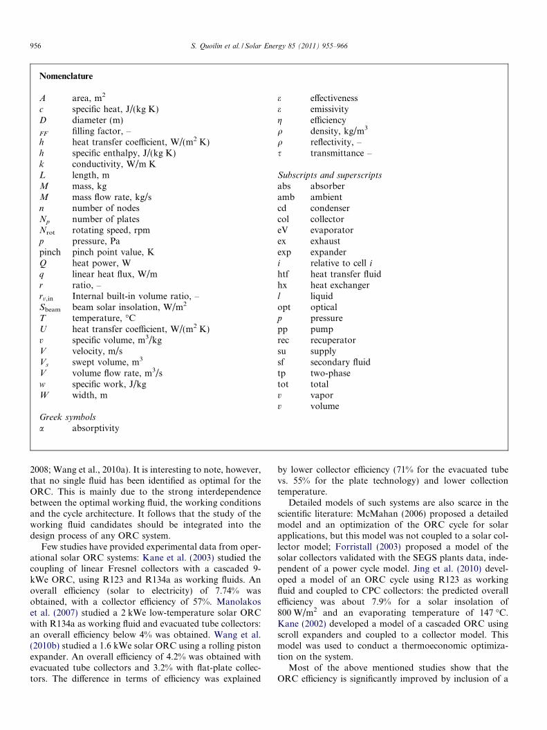
Researchers at MIT and University of Liege have col-laborated with the non-governmental organization STGInternational for the purpose of developing and imple-menting a small-scale solar thermal technology utilizingmedium temperature collectors and an ORC. A first unitwas installed by STG in 2007, and is shown in Fig. 1.
The goal is to provide rural areas of developing coun-tries with a system that can be manufactured and assem-bled locally (unlike PV collectors) and can replace orsupplement Diesel generators in off-grid areas, by generat-ing clean power at a lower levelized cost (Orosz et al.,2010).
At the core of this technology is a solar thermal powerplant consisting of a field of parabolic solar concentratingcollectors and a vapor expansion power block for generat-ing electricity. An electronic control unit is added forautonomous operation as sub-megawatt scale plants can-not justify the staffing of operating personnel. Operatingat a lower cycle temperatures (<200 �C) and Carnot effi-ciency is an example of a design tradeoff for maintaininglow cost at small scales. For a given level of output power,lower temperatures enable cost savings in the materials and
Fig. 1. Solar ORC prototype installed by STG in Lesotho.
manufacture of the absorber units, heat exchangers, fluidmanifolds and parabolic troughs.
Because no thermal power blocks are currently manu-factured in the kilowatt range a small-scale ORC has tobe designed for this application. The design is based onmodified commercially available components e.g. HVACscroll compressors (for the expander), and industrialpumps and heat exchangers. It should be noted that themain challenge for ORC development is the high cost ofspecially designed expander–generator equipment. At pres-ent, no volumetric expander is available on the market. Inorder to reduce the cost of a practicable system, the expan-der is obtained by adapting an off-the-shelf hermetic scrollcompressor to run in reverse, as proposed and successfullytested by Lemort et al. (2009a). Scroll machines show theadvantage of being widely available, reliable and with alimited number of moving parts (Zanelli and Favrat, 1994).
The goal of this paper is to design and dimension animproved solar ORC unit to be installed in a rural clinicin Berea District of Lesotho and to evaluate its perfor-mance with different working fluids. The main characteris-tics of this unit are the following:
� Target net output power: 3 kWe� Collector field: 75 m2 single-axis parabolic trough, using
Miro aluminum reflectors and a Heat Collection Ele-ment (HCE) with selective coating and air-filled annulusbetween absorber pipe and glazing.� ORC: One or two-stage expansion of R245fa using mod-
ified commercial HVAC compressors, brazed plate heatexchangers for high pressure heat transfer, and commer-cial HVAC tubes-and-fins air condenser for heatrejection.� Heat transfer fluid (HTF): Monoethylene glycol (MEG)
with thermal buffering in a thermal storage tank with a2 m3 packed bed of 19 mm quartzite.
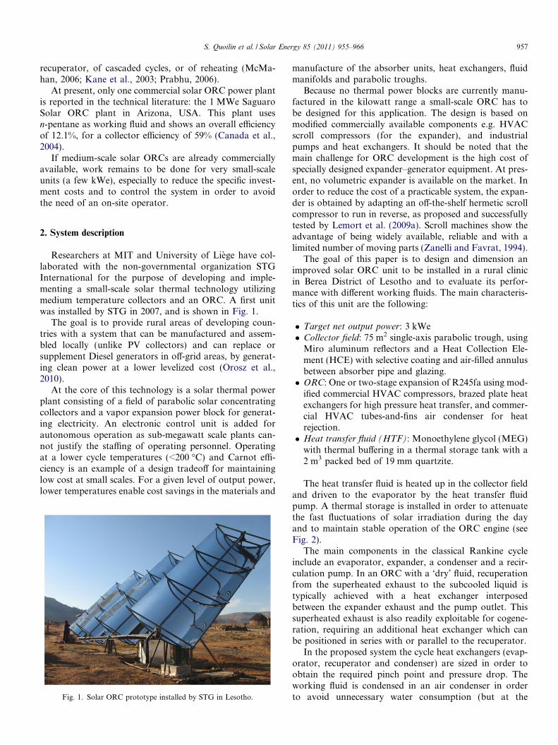
The heat transfer fluid is heated up in the collector fieldand driven to the evaporator by the heat transfer fluidpump. A thermal storage is installed in order to attenuatethe fast fluctuations of solar irradiation during the dayand to maintain stable operation of the ORC engine (seeFig. 2).
The main components in the classical Rankine cycleinclude an evaporator, expander, a condenser and a recir-culation pump. In an ORC with a ‘dry’ fluid, recuperationfrom the superheated exhaust to the subcooled liquid istypically achieved with a heat exchanger interposedbetween the expander exhaust and the pump outlet. Thissuperheated exhaust is also readily exploitable for cogene-ration, requiring an additional heat exchanger which canbe positioned in series with or parallel to the recuperator.
In the proposed system the cycle heat exchangers (evap-orator, recuperator and condenser) are sized in order toobtain the required pinch point and pressure drop. Theworking fluid is condensed in an air condenser in orderto avoid unnecessary water consumption (but at the
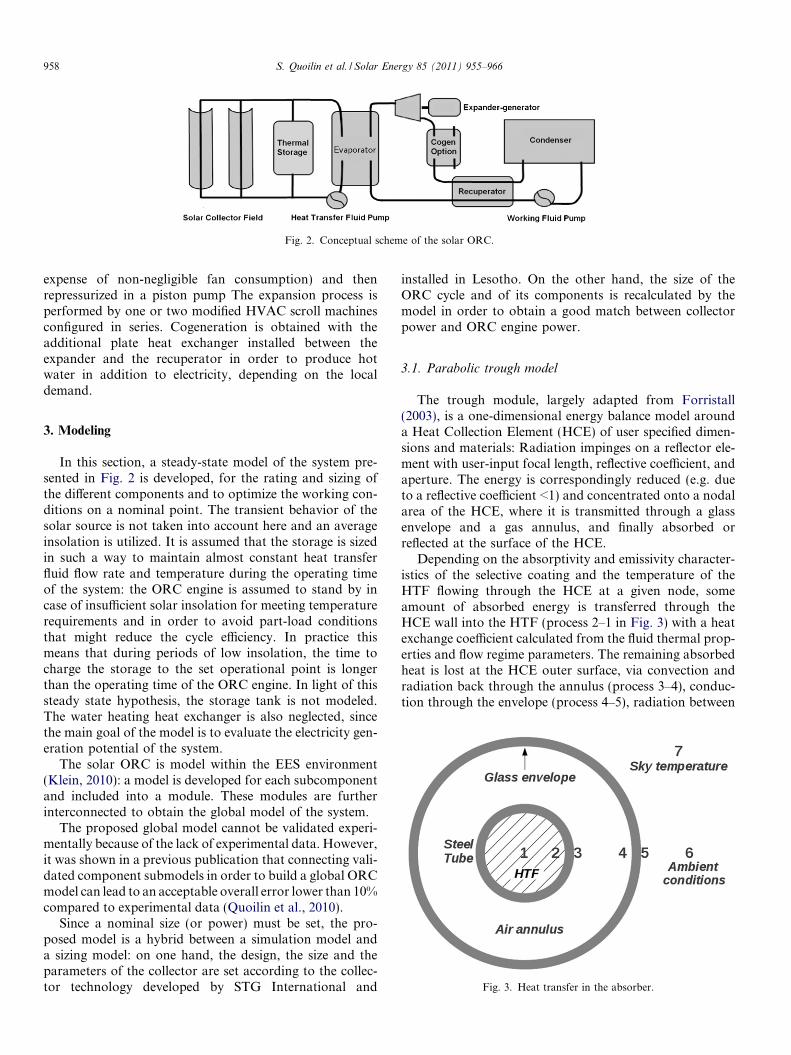
Fig. 2. Conceptual scheme of the solar ORC.
958 S. Quoilin et al. / Solar Energy 85 (2011) 955–966
expense of non-negligible fan consumption) and thenrepressurized in a piston pump The expansion process isperformed by one or two modified HVAC scroll machinesconfigured in series. Cogeneration is obtained with theadditional plate heat exchanger installed between theexpander and the recuperator in order to produce hotwater in addition to electricity, depending on the localdemand.
Fig. 3. Heat transfer in the absorber.
3. Modeling
In this section, a steady-state model of the system pre-sented in Fig. 2 is developed, for the rating and sizing ofthe different components and to optimize the working con-ditions on a nominal point. The transient behavior of thesolar source is not taken into account here and an averageinsolation is utilized. It is assumed that the storage is sizedin such a way to maintain almost constant heat transferfluid flow rate and temperature during the operating timeof the system: the ORC engine is assumed to stand by incase of insufficient solar insolation for meeting temperaturerequirements and in order to avoid part-load conditionsthat might reduce the cycle efficiency. In practice thismeans that during periods of low insolation, the time tocharge the storage to the set operational point is longerthan the operating time of the ORC engine. In light of thissteady state hypothesis, the storage tank is not modeled.The water heating heat exchanger is also neglected, sincethe main goal of the model is to evaluate the electricity gen-eration potential of the system.
The solar ORC is model within the EES environment(Klein, 2010): a model is developed for each subcomponentand included into a module. These modules are furtherinterconnected to obtain the global model of the system.
The proposed global model cannot be validated experi-mentally because of the lack of experimental data. However,it was shown in a previous publication that connecting vali-dated component submodels in order to build a global ORCmodel can lead to an acceptable overall error lower than 10%compared to experimental data (Quoilin et al., 2010).
Since a nominal size (or power) must be set, the pro-posed model is a hybrid between a simulation model anda sizing model: on one hand, the design, the size and theparameters of the collector are set according to the collec-tor technology developed by STG International and
installed in Lesotho. On the other hand, the size of theORC cycle and of its components is recalculated by themodel in order to obtain a good match between collectorpower and ORC engine power.
3.1. Parabolic trough model
The trough module, largely adapted from Forristall(2003), is a one-dimensional energy balance model arounda Heat Collection Element (HCE) of user specified dimen-sions and materials: Radiation impinges on a reflector ele-ment with user-input focal length, reflective coefficient, andaperture. The energy is correspondingly reduced (e.g. dueto a reflective coefficient <1) and concentrated onto a nodalarea of the HCE, where it is transmitted through a glassenvelope and a gas annulus, and finally absorbed orreflected at the surface of the HCE.
Depending on the absorptivity and emissivity character-istics of the selective coating and the temperature of theHTF flowing through the HCE at a given node, someamount of absorbed energy is transferred through theHCE wall into the HTF (process 2–1 in Fig. 3) with a heatexchange coefficient calculated from the fluid thermal prop-erties and flow regime parameters. The remaining absorbedheat is lost at the HCE outer surface, via convection andradiation back through the annulus (process 3–4), conduc-tion through the envelope (process 4–5), radiation between
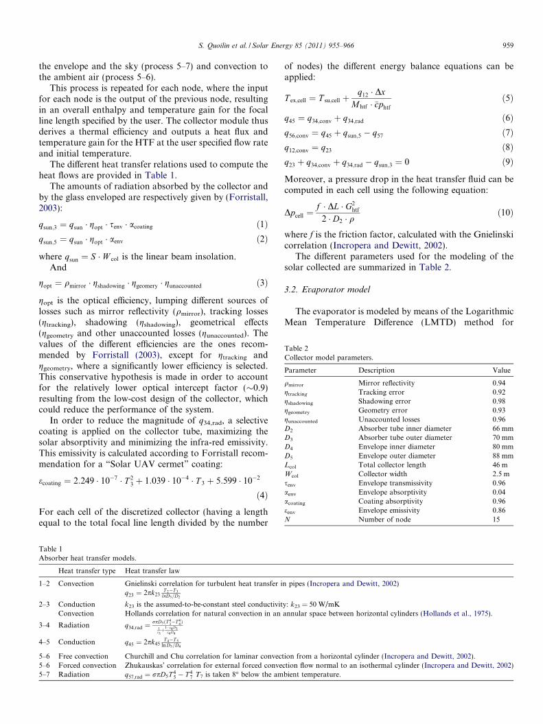
Table 2Collector model parameters.
Parameter Description Value
qmirror Mirror reflectivity 0.94gtracking Tracking error 0.92gshadowing Shadowing error 0.98ggeometry Geometry error 0.93gunaccounted Unaccounted losses 0.96D2 Absorber tube inner diameter 66 mmD3 Absorber tube outer diameter 70 mmD4 Envelope inner diameter 80 mmD5 Envelope outer diameter 88 mmLcol Total collector length 46 mWcol Collector width 2.5 msenv Envelope transmissivity 0.96aenv Envelope absorptivity 0.04acoating Coating absorptivity 0.96eenv Envelope emissivity 0.86N Number of node 15
S. Quoilin et al. / Solar Energy 85 (2011) 955–966 959
the envelope and the sky (process 5–7) and convection tothe ambient air (process 5–6).
This process is repeated for each node, where the inputfor each node is the output of the previous node, resultingin an overall enthalpy and temperature gain for the focalline length specified by the user. The collector module thusderives a thermal efficiency and outputs a heat flux andtemperature gain for the HTF at the user specified flow rateand initial temperature.
The different heat transfer relations used to compute theheat flows are provided in Table 1.
The amounts of radiation absorbed by the collector andby the glass enveloped are respectively given by (Forristall,2003):
qsun;3 ¼ qsun � gopt � senv � acoating ð1Þqsun;5 ¼ qsun � gopt � aenv ð2Þ
where qsun ¼ S � W col is the linear beam insolation.And
gopt ¼ qmirror � gshadowing � ggeomery � gunaccounted ð3Þ
gopt is the optical efficiency, lumping different sources oflosses such as mirror reflectivity (qmirror), tracking losses(gtracking), shadowing (gshadowing), geometrical effects(ggeometry and other unaccounted losses (gunaccounted). Thevalues of the different efficiencies are the ones recom-mended by Forristall (2003), except for gtracking andggeometry, where a significantly lower efficiency is selected.This conservative hypothesis is made in order to accountfor the relatively lower optical intercept factor (�0.9)resulting from the low-cost design of the collector, whichcould reduce the performance of the system.
In order to reduce the magnitude of q34,rad, a selectivecoating is applied on the collector tube, maximizing thesolar absorptivity and minimizing the infra-red emissivity.This emissivity is calculated according to Forristall recom-mendation for a “Solar UAV cermet” coating:
ecoating ¼ 2:249 � 10�7 � T 23 þ 1:039 � 10�4 � T 3 þ 5:599 � 10�2
ð4Þ
For each cell of the discretized collector (having a lengthequal to the total focal line length divided by the number
Table 1Absorber heat transfer models.
Heat transfer type Heat transfer law
1–2 Convection Gnielinski correlation for turbulent heat transfer iq23 ¼ 2pk23
T 2�T 3
lnD3=D2
2–3 Conduction k23 is the assumed-to-be-constant steel conductivitConvection Hollands correlation for natural convection in an
3–4 Radiation q34;rad ¼rpD3ðT 4
3�T 44Þ
1e3þ1�e4 D3
e4 D4
4–5 Conduction q45 ¼ 2pk45T 4�T 5
ln D5=D4
5–6 Free convection Churchill and Chu correlation for laminar convect5–6 Forced convection Zhukauskas’ correlation for external forced conve5–7 Radiation q57;rad ¼ rpD5T 4
5 � T 47 T7 is taken 8� below the am
of nodes) the different energy balance equations can beapplied:
T ex;cell ¼ T su;cell þq12 � Dx
Mhtf � �cphtf
ð5Þ
q45 ¼ q34;conv þ q34;rad ð6Þq56;conv ¼ q45 þ qsun;5 � q57 ð7Þq12;conv ¼ q23 ð8Þq23 þ q34;conv þ q34;rad � qsun;3 ¼ 0 ð9Þ
Moreover, a pressure drop in the heat transfer fluid can becomputed in each cell using the following equation:
Dpcell ¼f � DL � G2
htf
2 � D2 � qð10Þ
where f is the friction factor, calculated with the Gnielinskicorrelation (Incropera and Dewitt, 2002).
The different parameters used for the modeling of thesolar collected are summarized in Table 2.
3.2. Evaporator model
The evaporator is modeled by means of the LogarithmicMean Temperature Difference (LMTD) method for
n pipes (Incropera and Dewitt, 2002)
y: k23 = 50 W/mKannular space between horizontal cylinders (Hollands et al., 1975).
ion from a horizontal cylinder (Incropera and Dewitt, 2002).ction flow normal to an isothermal cylinder (Incropera and Dewitt, 2002)bient temperature.
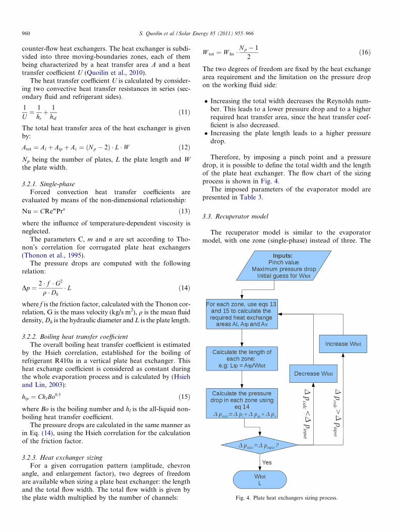
Fig. 4. Plate heat exchangers sizing process.
960 S. Quoilin et al. / Solar Energy 85 (2011) 955–966
counter-flow heat exchangers. The heat exchanger is subdi-vided into three moving-boundaries zones, each of thembeing characterized by a heat transfer area A and a heattransfer coefficient U (Quoilin et al., 2010).
The heat transfer coefficient U is calculated by consider-ing two convective heat transfer resistances in series (sec-ondary fluid and refrigerant sides).
1
U¼ 1
hrþ 1
hsf
ð11Þ
The total heat transfer area of the heat exchanger is givenby:
Atot ¼ Al þ Atp þ Av ¼ ðNp � 2Þ � L � W ð12Þ
Np being the number of plates, L the plate length and W
the plate width.
3.2.1. Single-phase
Forced convection heat transfer coefficients areevaluated by means of the non-dimensional relationship:
Nu ¼ CRemPrn ð13Þwhere the influence of temperature-dependent viscosity isneglected.
The parameters C, m and n are set according to Tho-non’s correlation for corrugated plate heat exchangers(Thonon et al., 1995).
The pressure drops are computed with the followingrelation:
Dp ¼ 2 � f � G2
q � Dh� L ð14Þ
where f is the friction factor, calculated with the Thonon cor-relation, G is the mass velocity (kg/s m2), q is the mean fluiddensity, Dh is the hydraulic diameter and L is the plate length.
3.2.2. Boiling heat transfer coefficient
The overall boiling heat transfer coefficient is estimatedby the Hsieh correlation, established for the boiling ofrefrigerant R410a in a vertical plate heat exchanger. Thisheat exchange coefficient is considered as constant duringthe whole evaporation process and is calculated by (Hsiehand Lin, 2003):
htp ¼ ChlBo0:5 ð15Þ
where Bo is the boiling number and hl is the all-liquid non-boiling heat transfer coefficient.
The pressure drops are calculated in the same manner asin Eq. (14), using the Hsieh correlation for the calculationof the friction factor.
3.2.3. Heat exchanger sizing
For a given corrugation pattern (amplitude, chevronangle, and enlargement factor), two degrees of freedomare available when sizing a plate heat exchanger: the lengthand the total flow width. The total flow width is given bythe plate width multiplied by the number of channels:
W tot ¼ W hx �N p � 1
2ð16Þ
The two degrees of freedom are fixed by the heat exchangearea requirement and the limitation on the pressure dropon the working fluid side:
� Increasing the total width decreases the Reynolds num-ber. This leads to a lower pressure drop and to a higherrequired heat transfer area, since the heat transfer coef-ficient is also decreased.� Increasing the plate length leads to a higher pressure
drop.
Therefore, by imposing a pinch point and a pressuredrop, it is possible to define the total width and the lengthof the plate heat exchanger. The flow chart of the sizingprocess is shown in Fig. 4.
The imposed parameters of the evaporator model arepresented in Table 3.
3.3. Recuperator model
The recuperator model is similar to the evaporatormodel, with one zone (single-phase) instead of three. The
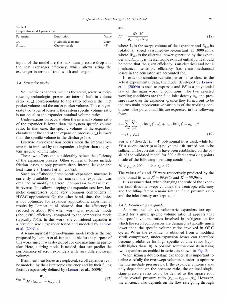
Table 3Evaporator model parameters.
Parameter Description Value
Dh Hydraulic diameter 2 mmbchevron Chevron angle 45�
S. Quoilin et al. / Solar Energy 85 (2011) 955–966 961
inputs of the model are the maximum pressure drop andthe heat exchanger efficiency, which allows sizing theexchanger in terms of total width and length.
3.4. Expander model
Volumetric expanders, such as the scroll, screw or recip-rocating technologies present an internal built-in volumeratio (rv,in) corresponding to the ratio between the inletpocket volume and the outlet pocket volume. This can gen-erate two types of losses if the system specific volume ratiois not equal to the expander nominal volume ratio:
Under-expansion occurs when the internal volume ratioof the expander is lower than the system specific volumeratio. In that case, the specific volume in the expansionchambers at the end of the expansion process (Pin) is lowerthan the specific volume in the discharge line.
Likewise over-expansion occurs when the internal vol-ume ratio imposed by the expander is higher than the sys-tem specific volume ratio.
These two effects can considerably reduce the efficiencyof the expansion process. Other sources of losses includefriction losses, supply pressure drop, internal leakage andheat transfers (Lemort et al., 2009a,b).
Since no off-the-shelf small-scale expansion machine iscurrently available on the market, the expander wasobtained by modifying a scroll compressor to make it runin reverse. This allows keeping the expander cost low, her-metic compressors being very common components inHVAC applications. On the other hand, since the deviceis not optimized for expander applications, experimentalresults by Lemort et al. showed that the efficiency isreduced by about 10% when working in expander mode(about 60% efficiency) compared to the compressor mode(typically 70%). In this work, the considered expander isa hermetic scroll expander tested and modeled by Lemortet al. (2009b).
A semi-empirical thermodynamic model such as the oneproposed by Lemort et al. is not suitable for the purpose ofthis work since it was developed for one machine in partic-ular. Here, a sizing model is needed, that can predict theperformance of scroll expanders with very different sweptvolumes.
If ambient heat losses are neglected, scroll expanders canbe modeled by their isentropic efficiency and by their fillingfactor, respectively defined by (Lemort et al., 2009b):
eexp ¼W exp
M � ðhsu; exp � hex; exp;sÞð17Þ
and
FF ¼ 60 �Mqsu � V s � Nrot
ð18Þ
where Vs is the swept volume of the expander and Nrot itsrotational speed (assumed-to-be-constant at 3000 rpm).where Wexp is the electrical power generated by the expan-der and hex,exp,s is the isentropic exhaust enthalpy. It shouldbe noted that the given efficiency is an electrical and not amechanical isentropic efficiency (i.e. electromechanicallosses in the generator are accounted for).
In order to simulate realistic performance close to theactual experimental data, the model developed by Lemortet al. (2009b) is used to express e and FF as a polynomiallaw of the main working conditions. The two selectedworking conditions are the fluid inlet density qsu and pres-sure ratio over the expander rp since they turned out to bethe two main representative variables of the working con-ditions. The polynomial fits are expressed in the followingform:
e ¼Xn�1
i¼0
Xn�1
j¼0
aij � lnðrpÞi � qjsu þ a0n � lnðrpÞn þ a0n � qn
1
¼ f ðrp; qsuÞ ð19Þ
For e, a 4th-order (n = 4) polynomial fit is used, while forFF a second-order (n = 2) polynomial fit turned out to besufficient. The correlations have been established on the ba-sis of the validated model for 800 different working pointsinside of the following operating conditions:
30 < qsu < 200; 1:2 < rp < 12
The values of e and FF were respectively predicted by thepolynomial fit with R2 = 99.98% and R2 = 99.96%.
It is assumed that, when changing the scale of the expan-der (and thus the swept volume), the isentropic efficiencyand the filling factor remain similar if the pressure ratioand the inlet density are kept equal.
3.4.1. Double-stage expander
As mentioned above, volumetric expanders are opti-mized for a given specific volume ratio. It appears thatthe specific volume ratios involved in refrigeration forwhich the scroll compressors are designed is typically muchlower than the specific volume ratios involved in ORCcycles. When the expander is obtained from a modifiedscroll compressor, under-expansion losses can thereforebecome prohibitive for high specific volume ratios (typi-cally higher than 10). A possible solution consists in usingtwo expanders assembled in series, as shown in Fig. 5.
When sizing a double-stage expander, it is important todefine carefully the two swept volumes in order to optimizethe intermediate pressure p2. If the expander efficiency wasonly dependent on the pressure ratio, the optimal single-stage pressure ratio would be defined as the square rootof the overall pressure ratio ðrp;1 ¼ rp;2 ¼
ffiffiffiffirpp Þ However,
the efficiency also depends on the flow rate going through
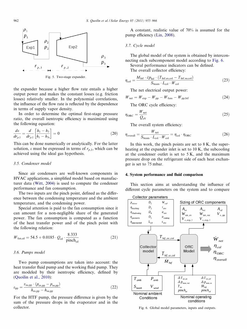
Fig. 5. Two-stage expander.
962 S. Quoilin et al. / Solar Energy 85 (2011) 955–966
the expander because a higher flow rate entails a higheroutput power and makes the constant losses (e.g. frictionlosses) relatively smaller. In the polynomial correlations,the influence of the flow rate is reflected by the dependencein terms of supply vapor density.
In order to determine the optimal first-stage pressureratio, the overall isentropic efficiency is maximized usingthe following equation:
dedrp;1
¼ ddrp;1
h1 � h3
h1 � h3s
� �¼ 0 ð20Þ
This can be done numerically or analytically. For the lattersolution, e must be expressed in terms of rp,1, which can beachieved using the ideal gas hypothesis.
3.5. Condenser model
Since air condensers are well-known components inHVAC applications, a simplified model based on manufac-turer data (Witt, 2004) is used to compute the condenserperformance and fan consumption.
The two inputs are the pinch point, defined as the differ-ence between the condensing temperature and the ambienttemperature, and the condensing power.
Special attention is paid to the fan consumption since itcan amount for a non-negligible share of the generatedpower. The fan consumption is computed as a functionof the heat transfer power and of the pinch point withthe following relation:
W fan;cd ¼ 54:5þ 0:0185 � Qcd �8:333
pinchcd
ð21Þ
Fig. 6. Global model parameters, inputs and outputs.
3.6. Pumps model
Two pump consumptions are taken into account: theheat transfer fluid pump and the working fluid pump. Theyare modeled by their isentropic efficiency, defined by(Quoilin et al., 2010):
epp ¼vsu;pp � ðpex;pp � psu;ppÞ
hex;pp � hsu;pp
ð22Þ
For the HTF pump, the pressure difference is given by thesum of the pressure drops in the evaporator and in thecollector.
A constant, realistic value of 70% is assumed for thepump efficiency (Lin, 2008).
3.7. Cycle model
The global model of the system is obtained by intercon-necting each subcomponent model according to Fig. 6.
Several performance indicators can be defined.The overall collector efficiency:
gcol ¼Mhtf � �cphtf � ðT htf ;ex;col � T htf ;su;colÞ
Sbeam � Lcol � W col
ð23Þ
The net electrical output power:
W net ¼ W exp � W pp � W fans � W pp;htf ð24Þ
The ORC cycle efficiency:
gORC ¼W net
QeV
ð25Þ
The overall system efficiency:
goverall ¼W net
Sbeam � Lcol � W col
¼ gcol � gORC ð26Þ
In this work, the pinch points are set to 8 K, the super-heating at the expander inlet is set to 10 K, the subcoolingat the condenser outlet is set to 5 K, and the maximumpressure drop on the refrigerant side of each heat exchan-ger is set to 75 mbar.
4. System performance and fluid comparison
This section aims at understanding the influence ofdifferent cycle parameters on the system and to compare
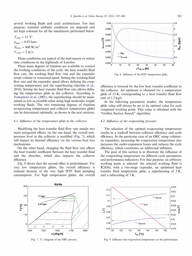
Fig. 8. Influence of the HTF temperature glide.
S. Quoilin et al. / Solar Energy 85 (2011) 955–966 963
several working fluids and cycle architectures. For thatpurpose, nominal ambient conditions are imposed andare kept constant for all the simulations performed below:
T amp ¼ 15 �C
pamp ¼ 0:83 bars
Sbeam ¼ 800 W=m2
V wind ¼ 2 m=s
These conditions are typical of the mid-season or wintertime conditions in the highlands of Lesotho.
Three main degrees of freedom are available to controlthe working conditions of the cycle: the heat transfer fluidflow rate, the working fluid flow rate and the expanderswept volume or rotational speed. Setting the working fluidflow rate and the expander speed allows defining the evap-orating temperature and the superheating (Quoilin et al.,2010). Setting the heat transfer fluid flow rate allows defin-ing the temperature glide in the collector. According toYamamoto et al. (2001), the superheating should be main-tained as low as possible when using high molecular weightworking fluids. The two remaining degrees of freedom(evaporating temperature and collector temperature glide)can be determined optimally, as shown in the next sections.
4.1. Influence of the temperature glide in the collector
Modifying the heat transfer fluid flow rate entails twomain antagonist effects: on the one hand, the overall tem-perature level in the collector is modified (Fig. 7), whichwill impact its thermal efficiency via the various heat lossmechanisms.
On the other hand, changing the fluid flow rate affectsthe heat transfer coefficient between the heat transfer fluidand the absorber, which also impacts the collectorefficiency.
Fig. 8 shows that the second effect is predominant: Forvery low temperature glides, the overall efficiency isreduced because of the very high HTF fluid pumpingconsumption. For high temperature glides, the overall
Fig. 7. T–s diagram of the ORC process.
efficiency is lowered by the low heat transfer coefficient inthe collector. An optimum is obtained for a temperatureglide of 15 K, corresponding to a heat transfer fluid flowrate of 1.2 kg/s.
In the following parametric studies, the temperatureglide value will always be set to its optimal value for eachcomputed working point. This value is obtained with the“Golden Section Search” algorithm.
4.2. Influence of the evaporating pressure
The selection of the optimal evaporating temperatureresults in a tradeoff between collector efficiency and cycleefficiency. In the particular case of an ORC using volumet-ric expanders, increasing the evaporation temperature alsoincreases the under-expansion losses and reduces the cycleefficiency, which constitutes an additional influence.
The goal of this section is to illustrate the influence ofthe evaporating temperature on different cycle parametersand performance indicators. For that purpose, an arbitraryworking point is selected: the selected working fluid isR245fa, with a two-stage expander, an optimized heattransfer fluid temperature glide, a superheating of 5 K,and a subcooling of 5 K.
Fig. 9. Influence the evaporation temperature on the performance.
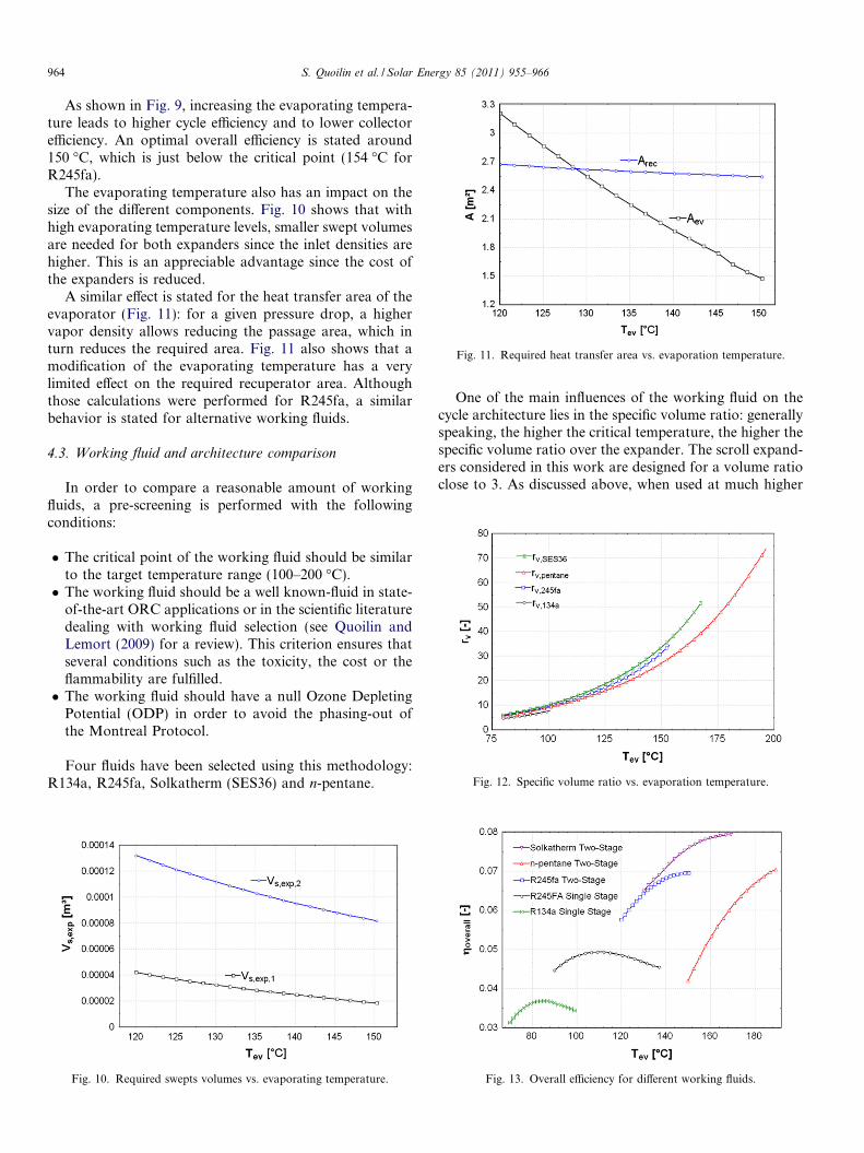
Fig. 11. Required heat transfer area vs. evaporation temperature.
Fig. 12. Specific volume ratio vs. evaporation temperature.
964 S. Quoilin et al. / Solar Energy 85 (2011) 955–966
As shown in Fig. 9, increasing the evaporating tempera-ture leads to higher cycle efficiency and to lower collectorefficiency. An optimal overall efficiency is stated around150 �C, which is just below the critical point (154 �C forR245fa).
The evaporating temperature also has an impact on thesize of the different components. Fig. 10 shows that withhigh evaporating temperature levels, smaller swept volumesare needed for both expanders since the inlet densities arehigher. This is an appreciable advantage since the cost ofthe expanders is reduced.
A similar effect is stated for the heat transfer area of theevaporator (Fig. 11): for a given pressure drop, a highervapor density allows reducing the passage area, which inturn reduces the required area. Fig. 11 also shows that amodification of the evaporating temperature has a verylimited effect on the required recuperator area. Althoughthose calculations were performed for R245fa, a similarbehavior is stated for alternative working fluids.
4.3. Working fluid and architecture comparison
In order to compare a reasonable amount of workingfluids, a pre-screening is performed with the followingconditions:
� The critical point of the working fluid should be similarto the target temperature range (100–200 �C).� The working fluid should be a well known-fluid in state-
of-the-art ORC applications or in the scientific literaturedealing with working fluid selection (see Quoilin andLemort (2009) for a review). This criterion ensures thatseveral conditions such as the toxicity, the cost or theflammability are fulfilled.� The working fluid should have a null Ozone Depleting
Potential (ODP) in order to avoid the phasing-out ofthe Montreal Protocol.
Four fluids have been selected using this methodology:R134a, R245fa, Solkatherm (SES36) and n-pentane.
Fig. 10. Required swepts volumes vs. evaporating temperature.
One of the main influences of the working fluid on thecycle architecture lies in the specific volume ratio: generallyspeaking, the higher the critical temperature, the higher thespecific volume ratio over the expander. The scroll expand-ers considered in this work are designed for a volume ratioclose to 3. As discussed above, when used at much higher
Fig. 13. Overall efficiency for different working fluids.
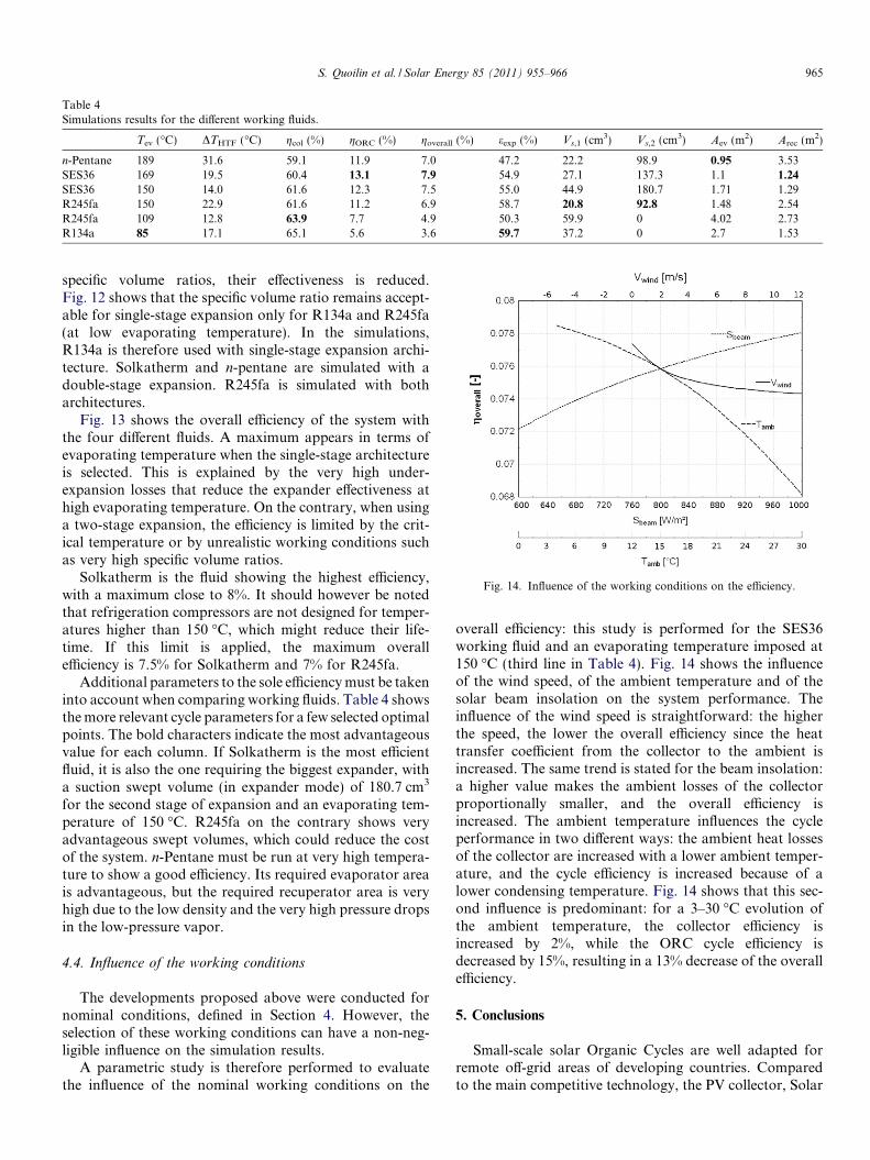
Table 4Simulations results for the different working fluids.
Tev (�C) DTHTF (�C) gcol (%) gORC (%) goverall (%) eexp (%) Vs,1 (cm3) Vs,2 (cm3) Aev (m2) Arec (m2)
n-Pentane 189 31.6 59.1 11.9 7.0 47.2 22.2 98.9 0.95 3.53SES36 169 19.5 60.4 13.1 7.9 54.9 27.1 137.3 1.1 1.24
SES36 150 14.0 61.6 12.3 7.5 55.0 44.9 180.7 1.71 1.29R245fa 150 22.9 61.6 11.2 6.9 58.7 20.8 92.8 1.48 2.54R245fa 109 12.8 63.9 7.7 4.9 50.3 59.9 0 4.02 2.73R134a 85 17.1 65.1 5.6 3.6 59.7 37.2 0 2.7 1.53
Fig. 14. Influence of the working conditions on the efficiency.
S. Quoilin et al. / Solar Energy 85 (2011) 955–966 965
specific volume ratios, their effectiveness is reduced.Fig. 12 shows that the specific volume ratio remains accept-able for single-stage expansion only for R134a and R245fa(at low evaporating temperature). In the simulations,R134a is therefore used with single-stage expansion archi-tecture. Solkatherm and n-pentane are simulated with adouble-stage expansion. R245fa is simulated with botharchitectures.
Fig. 13 shows the overall efficiency of the system withthe four different fluids. A maximum appears in terms ofevaporating temperature when the single-stage architectureis selected. This is explained by the very high under-expansion losses that reduce the expander effectiveness athigh evaporating temperature. On the contrary, when usinga two-stage expansion, the efficiency is limited by the crit-ical temperature or by unrealistic working conditions suchas very high specific volume ratios.
Solkatherm is the fluid showing the highest efficiency,with a maximum close to 8%. It should however be notedthat refrigeration compressors are not designed for temper-atures higher than 150 �C, which might reduce their life-time. If this limit is applied, the maximum overallefficiency is 7.5% for Solkatherm and 7% for R245fa.
Additional parameters to the sole efficiency must be takeninto account when comparing working fluids. Table 4 showsthe more relevant cycle parameters for a few selected optimalpoints. The bold characters indicate the most advantageousvalue for each column. If Solkatherm is the most efficientfluid, it is also the one requiring the biggest expander, witha suction swept volume (in expander mode) of 180.7 cm3
for the second stage of expansion and an evaporating tem-perature of 150 �C. R245fa on the contrary shows veryadvantageous swept volumes, which could reduce the costof the system. n-Pentane must be run at very high tempera-ture to show a good efficiency. Its required evaporator areais advantageous, but the required recuperator area is veryhigh due to the low density and the very high pressure dropsin the low-pressure vapor.
4.4. Influence of the working conditions
The developments proposed above were conducted fornominal conditions, defined in Section 4. However, theselection of these working conditions can have a non-neg-ligible influence on the simulation results.
A parametric study is therefore performed to evaluatethe influence of the nominal working conditions on the
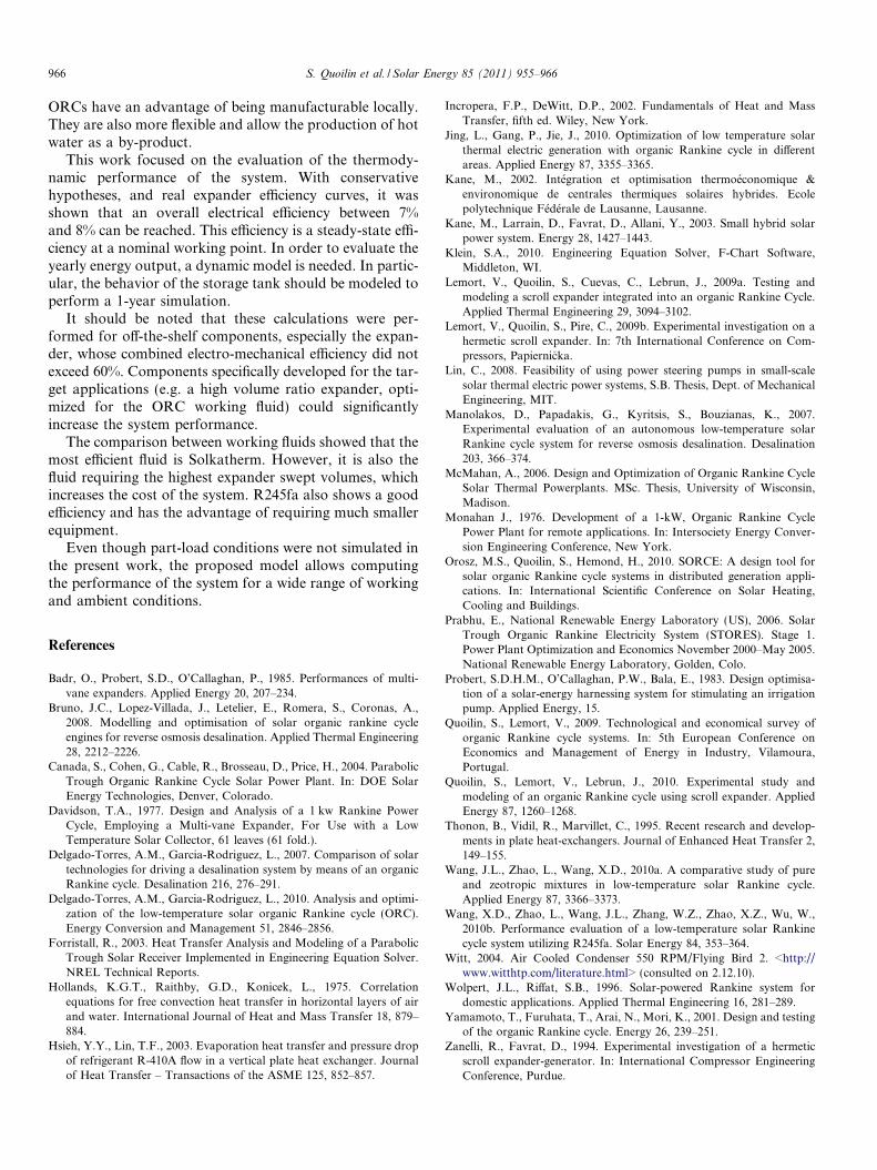
overall efficiency: this study is performed for the SES36working fluid and an evaporating temperature imposed at150 �C (third line in Table 4). Fig. 14 shows the influenceof the wind speed, of the ambient temperature and of thesolar beam insolation on the system performance. Theinfluence of the wind speed is straightforward: the higherthe speed, the lower the overall efficiency since the heattransfer coefficient from the collector to the ambient isincreased. The same trend is stated for the beam insolation:a higher value makes the ambient losses of the collectorproportionally smaller, and the overall efficiency isincreased. The ambient temperature influences the cycleperformance in two different ways: the ambient heat lossesof the collector are increased with a lower ambient temper-ature, and the cycle efficiency is increased because of alower condensing temperature. Fig. 14 shows that this sec-ond influence is predominant: for a 3–30 �C evolution ofthe ambient temperature, the collector efficiency isincreased by 2%, while the ORC cycle efficiency isdecreased by 15%, resulting in a 13% decrease of the overallefficiency.
5. Conclusions
Small-scale solar Organic Cycles are well adapted forremote off-grid areas of developing countries. Comparedto the main competitive technology, the PV collector, Solar
966 S. Quoilin et al. / Solar Energy 85 (2011) 955–966
ORCs have an advantage of being manufacturable locally.They are also more flexible and allow the production of hotwater as a by-product.
This work focused on the evaluation of the thermody-namic performance of the system. With conservativehypotheses, and real expander efficiency curves, it wasshown that an overall electrical efficiency between 7%and 8% can be reached. This efficiency is a steady-state effi-ciency at a nominal working point. In order to evaluate theyearly energy output, a dynamic model is needed. In partic-ular, the behavior of the storage tank should be modeled toperform a 1-year simulation.
It should be noted that these calculations were per-formed for off-the-shelf components, especially the expan-der, whose combined electro-mechanical efficiency did notexceed 60%. Components specifically developed for the tar-get applications (e.g. a high volume ratio expander, opti-mized for the ORC working fluid) could significantlyincrease the system performance.
The comparison between working fluids showed that themost efficient fluid is Solkatherm. However, it is also thefluid requiring the highest expander swept volumes, whichincreases the cost of the system. R245fa also shows a goodefficiency and has the advantage of requiring much smallerequipment.
Even though part-load conditions were not simulated inthe present work, the proposed model allows computingthe performance of the system for a wide range of workingand ambient conditions.
References
Badr, O., Probert, S.D., O’Callaghan, P., 1985. Performances of multi-vane expanders. Applied Energy 20, 207–234.
Bruno, J.C., Lopez-Villada, J., Letelier, E., Romera, S., Coronas, A.,2008. Modelling and optimisation of solar organic rankine cycleengines for reverse osmosis desalination. Applied Thermal Engineering28, 2212–2226.
Canada, S., Cohen, G., Cable, R., Brosseau, D., Price, H., 2004. ParabolicTrough Organic Rankine Cycle Solar Power Plant. In: DOE SolarEnergy Technologies, Denver, Colorado.
Davidson, T.A., 1977. Design and Analysis of a 1 kw Rankine PowerCycle, Employing a Multi-vane Expander, For Use with a LowTemperature Solar Collector, 61 leaves (61 fold.).
Delgado-Torres, A.M., Garcia-Rodriguez, L., 2007. Comparison of solartechnologies for driving a desalination system by means of an organicRankine cycle. Desalination 216, 276–291.
Delgado-Torres, A.M., Garcia-Rodriguez, L., 2010. Analysis and optimi-zation of the low-temperature solar organic Rankine cycle (ORC).Energy Conversion and Management 51, 2846–2856.
Forristall, R., 2003. Heat Transfer Analysis and Modeling of a ParabolicTrough Solar Receiver Implemented in Engineering Equation Solver.NREL Technical Reports.
Hollands, K.G.T., Raithby, G.D., Konicek, L., 1975. Correlationequations for free convection heat transfer in horizontal layers of airand water. International Journal of Heat and Mass Transfer 18, 879–884.
Hsieh, Y.Y., Lin, T.F., 2003. Evaporation heat transfer and pressure dropof refrigerant R-410A flow in a vertical plate heat exchanger. Journalof Heat Transfer – Transactions of the ASME 125, 852–857.
Incropera, F.P., DeWitt, D.P., 2002. Fundamentals of Heat and MassTransfer, fifth ed. Wiley, New York.
Jing, L., Gang, P., Jie, J., 2010. Optimization of low temperature solarthermal electric generation with organic Rankine cycle in differentareas. Applied Energy 87, 3355–3365.
Kane, M., 2002. Integration et optimisation thermoeconomique &environomique de centrales thermiques solaires hybrides. Ecolepolytechnique Federale de Lausanne, Lausanne.
Kane, M., Larrain, D., Favrat, D., Allani, Y., 2003. Small hybrid solarpower system. Energy 28, 1427–1443.
Klein, S.A., 2010. Engineering Equation Solver, F-Chart Software,Middleton, WI.
Lemort, V., Quoilin, S., Cuevas, C., Lebrun, J., 2009a. Testing andmodeling a scroll expander integrated into an organic Rankine Cycle.Applied Thermal Engineering 29, 3094–3102.
Lemort, V., Quoilin, S., Pire, C., 2009b. Experimental investigation on ahermetic scroll expander. In: 7th International Conference on Com-pressors, Papiernicka.
Lin, C., 2008. Feasibility of using power steering pumps in small-scalesolar thermal electric power systems, S.B. Thesis, Dept. of MechanicalEngineering, MIT.
Manolakos, D., Papadakis, G., Kyritsis, S., Bouzianas, K., 2007.Experimental evaluation of an autonomous low-temperature solarRankine cycle system for reverse osmosis desalination. Desalination203, 366–374.
McMahan, A., 2006. Design and Optimization of Organic Rankine CycleSolar Thermal Powerplants. MSc. Thesis, University of Wisconsin,Madison.
Monahan J., 1976. Development of a 1-kW, Organic Rankine CyclePower Plant for remote applications. In: Intersociety Energy Conver-sion Engineering Conference, New York.
Orosz, M.S., Quoilin, S., Hemond, H., 2010. SORCE: A design tool forsolar organic Rankine cycle systems in distributed generation appli-cations. In: International Scientific Conference on Solar Heating,Cooling and Buildings.
Prabhu, E., National Renewable Energy Laboratory (US), 2006. SolarTrough Organic Rankine Electricity System (STORES). Stage 1.Power Plant Optimization and Economics November 2000–May 2005.National Renewable Energy Laboratory, Golden, Colo.
Probert, S.D.H.M., O’Callaghan, P.W., Bala, E., 1983. Design optimisa-tion of a solar-energy harnessing system for stimulating an irrigationpump. Applied Energy, 15.
Quoilin, S., Lemort, V., 2009. Technological and economical survey oforganic Rankine cycle systems. In: 5th European Conference onEconomics and Management of Energy in Industry, Vilamoura,Portugal.
Quoilin, S., Lemort, V., Lebrun, J., 2010. Experimental study andmodeling of an organic Rankine cycle using scroll expander. AppliedEnergy 87, 1260–1268.
Thonon, B., Vidil, R., Marvillet, C., 1995. Recent research and develop-ments in plate heat-exchangers. Journal of Enhanced Heat Transfer 2,149–155.
Wang, J.L., Zhao, L., Wang, X.D., 2010a. A comparative study of pureand zeotropic mixtures in low-temperature solar Rankine cycle.Applied Energy 87, 3366–3373.
Wang, X.D., Zhao, L., Wang, J.L., Zhang, W.Z., Zhao, X.Z., Wu, W.,2010b. Performance evaluation of a low-temperature solar Rankinecycle system utilizing R245fa. Solar Energy 84, 353–364.
Witt, 2004. Air Cooled Condenser 550 RPM/Flying Bird 2. <http://www.witthtp.com/literature.html> (consulted on 2.12.10).
Wolpert, J.L., Riffat, S.B., 1996. Solar-powered Rankine system fordomestic applications. Applied Thermal Engineering 16, 281–289.
Yamamoto, T., Furuhata, T., Arai, N., Mori, K., 2001. Design and testingof the organic Rankine cycle. Energy 26, 239–251.
Zanelli, R., Favrat, D., 1994. Experimental investigation of a hermeticscroll expander-generator. In: International Compressor EngineeringConference, Purdue.