cfd-assisted design and optimization of solar chimneys · pdf filecfd-assisted design and...
TRANSCRIPT

CFD-ASSISTED DESIGN AND OPTIMIZATION OF SOLAR CHIMNEYS FOR ELEMENTARY SCHOOL CLASSROOMS
Justin C. DeBlois1, Demba Ndiaye2
1Setty and Associates, New York, NY 2University of North Carolina at Charlotte, Charlotte, NC
ABSTRACT A passive ventilation system using solar chimneys was designed to provide ventilation to several classrooms in an addition to an elementary school in Washington, DC. The primary design objectives were to provide enhanced indoor environmental quality and a learning opportunity for students. This paper explores the design process, describes obstacles faced in implementing the design, and presents the results of the simulations. The multi-variable optimization approach taken to the design, using a detailed airflow model in EnergyPlus and CFD, attempted to find the design parameters such as chimney height and opening areas that result in the highest number of occupied hours per year with adequate ventilation flow rates. EnergyPlus results show potential HVAC energy savings of up to 5%, and up to 1,200 occupied hours that the classrooms could have adequate natural ventilation. CFD results complement these simulations by demonstrating the ranges of exterior temperatures and ventilation flow rates that are thermally comfortable. Comprehensive analysis with simulation tools allowed an optimal design for this complex, multi-variable problem.
INTRODUCTION The solar chimney is a natural ventilation technique that uses an open construction extending above the building to allow buoyancy driven ventilation to flow up from the occupied space through a vent near the top of the chimney. Solar chimneys use the buoyancy force from warm interior air near the ceilings of the rooms and also take advantage of solar radiation by allowing the insolation to pass through a South-facing window in the chimney and be absorbed by the dark, low-reflectivity interior surfaces of the chimney. Natural convection then causes the air in the chimney to warm and flow upward and out of the vent. Numerous recent studies have examined the use of solar chimneys in residential, educational and a variety of other building types. The two story design of Powell elementary school is unusual in the literature. A literature review on the solar chimney research showed that the solar chimney system is still not completely understood (Khanal, 2011). The literature is split between Computational Fluid
Dynamics (CFD) studies, numerical studies and experimental studies. Much of the literature focuses on optimizing the chimney height, tilt angle and width for a specific climate and set of environmental conditions. A research group recently developed a module for implementation in EnergyPlus that would calculate the performance of an inclined solar chimney, and conducted a cursory experimental validation (Jianliu, 2013). The module was not available for use in this paper. The authors further attempted to find the optimum tilt for the Nanjing (China) climate. Another study of the inclined solar chimney used mathematical analysis and experimental validation to study the inclination angle and chimney gap width for specific, steady state, environmental conditions (Khanal, 2014). A paper looked into the effect of wind speed on solar chimney performance, something which is often overlooked in the literature but which is key to a successful design (Tan, 2014). For the Powell project, the annual EnergyPlus simulations also include the effect of wind. Literature often relies on CFD to model the air flow in solar chimneys. The scope of these studies is often smaller than the scope of the Powell study, such that CFD does not predict the actual thermal comfort in the space. For example, one group uses CFD to predict the performance of a residential solar chimney, and then validates it experimentally (Chung, 2014). Another uses CFD to parametrically study the effect of glass tilt angle and air gap width on performance, and again the scope of the model is limited to the chimney itself (Lal, 2014). Despite the challenges of using a ventilation technique which is not fully understood from an academic perspective, solar chimneys were identified early in the design process for the Powell Elementary School addition and renovation project as a strategy for improving the indoor environmental quality of the classrooms and for providing an educational tool on green buildings. Figure 1 shows a design of the solar chimney in the Revit model of the addition, Building C. The two tall structures above the eight classrooms are solar chimneys.
Proceedings of BS2015: 14th Conference of International Building Performance Simulation Association, Hyderabad, India, Dec. 7-9, 2015.
- 818 -

Figure 1: Eight classrooms served by two vertical
solar chimneys
Each solar chimney served four classrooms: two on the first floor and two on the second floor. The chimney spans the two floors and has vents into each of the classrooms, as well as a vent and fenestration surface near the top of the chimney. An advanced control system is required to automatically actuate the vent openings, as well as possibly control a ventilation fan in the solar chimney. The operation of the ventilation system is occupant controlled, by a switch and an automated control system.
SIMULATIONS The building energy model of the Powell classrooms and solar chimneys went through two iterations. The first iteration was based off standard classroom assumptions and a preliminary chimney design. A sensitivity analysis was conducted with the design suggested by the NIST software LoopDA (Dols et al., 2012) as the center point. The second iteration used the actual designed constructions and expected operational characteristics for the building, and a multi-dimensional analysis of the key design variables was conducted that accounted for the interactions between parameters. A CFD model was developed of the space to simultaneously assess the thermal comfort performance of the advanced natural ventilation strategy and inform the zonal models on possible comfortable flow modes.
First Iteration Zonal Model The first model, developed in an EnergyPlus (EnergyPlus, 2014) front end, was the simplest zonal representation that could capture the dynamics of the solar chimney while excluding the rest of the building. The airflow patterns on the first and second floor are different because of the difference in inlet heights, so two stories were included. While each solar chimney serves two classrooms on each floor, the two are symmetric with little heat transfer between them because there are no openings between them and the set points and activity schedules in each
are identical. Therefore, one classroom was simulated on each floor and the shared wall was considered adiabatic, or without heat transfer. The South walls of the classrooms were also considered adiabatic because they face a conditioned corridor with temperature set points identical to the classrooms and separate conditioning systems. Figure 2 shows the visualization of the model.
Figure 2: First iteration model visualization
There is a South-facing, sloped window on the back of the solar chimney. This window has area 72 ft2, and a sloped angle of 22° from the vertical. This window is placed to maximize solar radiation allowed into the chimney, to be absorbed by the low-reflectivity coating in the chimney and convected to the internal air to cause upward airflow. The window is double-paned, without a low-e coating. The airflow network includes three zone air nodes: the first and second floor classrooms and the solar chimney. There are two fixed and three operable openings. The vents between the classroom and the solar chimney were fixed open and could not be controlled dynamically at this point in the study due to limitations within the EnergyPlus front end. The bottom portions of the two main classroom windows and the vent from the chimney to the exterior were operable and controlled automatically. There were exterior air nodes corresponding to each of the exterior openings, at the appropriate height. The wind flow coefficients were calculated according to an EnergyPlus algorithm tailored to the approximate geometry of the building.
Second Iteration Zonal Model For the second iteration of the model, more care was taken to match the constructions and geometry of the building as it is designed. The second iteration included four classrooms, in case there were any asymmetrical aspects to the heat transfer. The constructions matched the intended design, and the assumed heat gains and schedules were carefully matched to the expected usage patterns of the building. Gains included people, lights, and solar. Equipment gain is relatively small in this type of space. For all annual simulations, an annual schedule
Proceedings of BS2015: 14th Conference of International Building Performance Simulation Association, Hyderabad, India, Dec. 7-9, 2015.
- 819 -

was created with three seasons: academic year, summer, and vacation. Only the academic year was considered an occupied time period. Therefore, the peak cooling season, and a time when the natural ventilation system might be very effective, was not included in the analysis because the system will not operate during the summer when the building is unoccupied. See Figure 5 for a summary of the external conditions during occupied time steps. The second iteration model controlled the ventilation openings only roughly, and rather focused on the airflow and the effects of changing opening sizes on the flow patterns. Figure 3 shows the second iteration of the EnergyPlus model.
Figure 3: Second iteration model visualization
Figure 4 shows the nodal layout. The airflow network included five zone air nodes: the first and second floor classrooms (nodes A and B) and the solar chimney (node c). There were four fixed and five operable openings. The vents from between the classrooms and the solar chimney were fixed open. The bottom portions of the two main classroom windows and the vent from the chimney to the exterior were operable and were controlled based on the occupancy of the space. The window opening areas for this model iteration are 36 ft2, per the architectural design.
Figure 4: Second iteration nodal visualization
The window and vent areas were modulated automatically by the model, according to external conditions. In the application of this ventilation system to Powel Elementary School, an automatic controls system was designed to modulate openings. A backdraft damper was included in the final design to prevent reverse flow. The teacher also has manual control over the window openings, as will be discussed further. Localized control was provided in each classroom to give teachers the ability to determine when natural ventilation will be used. These features were left out of the controls simulation for this stage of the model. The optimization focused on designing the physical systems to provide a mechanism for reliable, comfortable flow that could then be further enhanced with controls. Computational Fluid Dynamics Model A classroom layout based on the typical desk layout observed on visits to elementary schools was developed for the CFD model. The presence of occupants and furniture has two effects on the CFD analysis. Both types of objects block airflow and influence the air patterns. The occupants also add heat to the surrounding air, influencing the air temperature distribution and causing buoyancy induced flow plumes surrounding occupants. Twenty students and one teacher were simulated in each classroom. Figure 5 shows the generic classroom layout used in the simulations.
Proceedings of BS2015: 14th Conference of International Building Performance Simulation Association, Hyderabad, India, Dec. 7-9, 2015.
- 820 -

Figure 5: CFD model schematic
The CFD model used a K-ε RNG turbulence model, and a rectilinear grid. This grid was the only one offered by the available CFD program. The heat boundary conditions on walls and openings were constant temperature, and the occupants were constant heat flux. All solid surfaces had 0 velocity boundary conditions and openings had constant flow rate boundary conditions. The computational time was 10 to 20 minutes on a 3 GHZ Pentium laptop.
RESULTS ANALYSIS With an initial design point determined through schematic design and a preliminary calculation with LoopDA, a sensitivity analysis was conducted for a few design variables with the more coarse, first iteration zonal energy model.
Parametric Optimization Dynamic simulations were conducted varying several variables by up to ± 40 %. The results were assessed by comparing the airflow rates for six time steps gauged to represent a wide range of weather conditions for which the chimney would likely be operating. Table 1 shows the general conclusions.
Table 1: Sensitivity Analysis Overview for ± 40 % change in primary variable
VARIABLE OUTPUTS CONCLUSION Chimney height ± 20 % Further study Window opening ± 5 % Code minimum is
sufficient Window ratio by Floor
± 5 % Not important
Vent size - Classrooms
± 25 % Further study
Vent ratio by floor
± 15 % Further study
As expected, there was significant sensitivity in the flow rate to the height of the chimney. The flow was also sensitive to the size of the internal and external chimney vents – the major restrictions to flow. The ratio of the vents on the first floor to the second floor may affect the flow due to imbalance between floor heights. The window area, however, which was determined according to ASHRAE guidelines for
naturally ventilating a space, provided very little resistance to flow compared to the vents. These sensitivity analyses give an insight into how different design parameters influence the steady state performance of the solar chimney. However, to further the design, a more in-depth analysis was required. The scope of the first iteration sensitivity analysis was limited because it only looked at six time steps. The fact that the analyses were centered around one baseline design point limited the usefulness of the results. In addition, the first iteration model only looked at one side of the solar chimney rather than two classrooms per floor, and did not use the design constructions for the wall and window materials. The second iteration model was used to do a very simple multi-variable, parametric, optimization on the remaining design parameters. Two to three scenarios were examined for four variables, as shown in Table 2.
Table 2: Parametric space for analysis Scenario Chimney
Vent Height (ft)
Vent 3 Free Area (ft2)
Vent 2 Free Area (ft2)
Vent 1 Free Area (ft2)
A 39.25 16 4.5 8 B 45.25 12 6 6 C 3 10
In this table, Vent 1 is the size of the vents from the first floor classrooms to the chimney, Vent 2 is the same for the second floor, and Vent 3 is the vent at the top of the solar chimney. Chimney vent height is measured from the ground level. In order to obtain a more useful evaluation of the performance of the chimney, the output metric for the analysis was hours of natural ventilation for a simulated year. This was the number of total occupied hours for which the solar chimney provided adequate ventilation when the windows and vents were open. Adequate ventilation was defined based on the outside air requirements of ASHRAE Standard 62.1. The conditions for ventilation were limited to between 50°F and 80°F outside air temperature and 62.2 maximum outside air dew point temperature. The minimum outside air temperature was determined through CFD simulations of the thermal comfort in the space for different temperatures. Below 50°F, entering air has a high probability of causing perceptions of draft and discomfort. Above 80°F, outside air or zone air temperature requires mechanical cooling for comfort, according to the school’s conditioning requirements. The entering air dew point of 62.2°F is considered by ASHRAE Standard 55 to be the maximum for passive ventilation air for thermal comfort. The total number of occupied hours in this climate meeting these requirements is approximately 1,302 per year, or 49.8% of occupied hours. The objective
Proceedings of BS2015: 14th Conference of International Building Performance Simulation Association, Hyderabad, India, Dec. 7-9, 2015.
- 821 -

of this parametric analysis was to find the design that would provide at least the minimum flow rate of 325 cfm to each of the four classrooms for the most of these eligible hours. From the table above it can be seen that to cover the entire space, 2x2x3x3, or 36 simulations are required. After completing the simulations for each case and analyzing the results, the best performing combination was with 45.25 ft chimney vent height, 12 ft2 chimney exterior vent free area, 6 ft2 interior vent free area in the first and second floor classrooms. This scenario provided adequate ventilation for all four classrooms for 1,236 occupied hours, or 95.0% of the hours that met the requirements for ventilation described above, and 49.8% of the total occupied hours. However, the parametric with a shorter chimney but equivalent vent sizes shows a very similar performance without the added height of a higher solar chimney. The performance trade-off was judged to be minimal, and the 39.25 height was the final design variable. The design parameters are summarized in Table 3.
Table 3: Optimized design parameters VARIABLE VALUE
Exterior Vent Free Area 16 ft2 First Floor Classroom Vent
Free Area 6 ft2
Second Floor Classroom Vent
Free Area 6 ft2
Solar Chimney Height Ground to Ext. Vent Center
39.25 ft
Comfort Modeling A CFD module was used to study the thermal comfort for a range of conditions of ventilation. From the simulation outputs for the proposed design, it was determined that average hourly flow rates ranged from 325 cfm to 1,000 cfm at 50 to 80 °F. CFD simulations were conducted for the flow rates of approximately 325, 800 and 1000 cfm at 55, 65 and 75°F outside entering air. ASHRAE Standard 55 gives guidelines for the maximum average space air velocity for mechanically ventilated spaces. While occupants are more tolerant of air movement in a naturally ventilated space, these numbers still provide some insight into what an acceptable level of draft is. The air velocity perceived as comfortable depends on the air temperature. Table 4 shows the ASHRAE maximum flow rates for mechanically ventilated spaces for 80% comfort at different temperatures.
Table 4: ASHRAE draft recommendations for mechanically ventilated spaces
AIR TEMPERATURE ACCEPTABLE FPM
(°F) FOR 80% COMFORT 50 33.0 55 38.0 60 45.1 65 55.6 70 72.2 75 101.5 80 161.9
Although occupants can be much more forgiving of a wider range of conditions in a naturally ventilated space compared to a mechanically ventilated one, there are no similar guidelines for naturally ventilated spaces and these were used as a reference. Nine time steps, or simulation hours, representing high, medium and low flow rates in three different temperature ranges were chosen for a comfort analysis using CFD. The domain with each time step is graphed in Figure 6. The nine sample hours should give an indication of the thermal comfort experienced by the teacher and students in a variety of chimney operational conditions. As a demonstration of the useful results of the CFD studies, Figure 7 shows the entering air velocity for the low flow, low temperature scenario. Figure 7 shows that the velocity near the window may reach up to 70 fpm, but at three feet from the window, the velocity has decreased to below 40 fpm. This is approximately equal to the maximum allowed by ASHRAE for a mechanically ventilated space at this temperature. Therefore, the natural ventilation system can be used at an outside air temperature of 55°F, but only in low flow conditions with low wind, or with the flow modulated by the automatic dampers.
Figure 6: Ventilation flow rate and temperature
scatter plot for occupied time steps
Proceedings of BS2015: 14th Conference of International Building Performance Simulation Association, Hyderabad, India, Dec. 7-9, 2015.
- 822 -

Figure 7: Low temperature, low flow velocity plot perpendicular to the window
When studying the airflow with CFD for all nine of the flow/temperature scenarios, it became apparent that for the predicted rates of airflow, velocity and draft are comfortable for the majority of conditions. The analysis showed that for some time steps, the rooms reached temperatures in the low 60s°F. This may be a comfort issue for some occupants, but the temperature in the room is a function of more than the outside conditions and ventilation rate – the thermal mass, occupancy rate and other factors come into play. For this reason, and due to the original desire of the owners’ for the solar chimney system to be an educational tool, each classroom was equipped with local control for the highest priority designation of the ventilation mode. The lowest flow temperatures corresponded with low outside air temperatures, and were near the windows and along the floor of the classroom. The air velocities were highest immediately at the window and vent openings, and would likely be uncomfortable at these points. However, studying the velocities at up to 3 ft from the openings it was clear that the flow had diffused enough that the velocity experienced by occupants would be within the guidelines even for the average experienced in a mechanically ventilated space. The flow tended to form a circular pattern in through the window, up along the far wall, and back along the ceiling toward the window. The flow through the window was uniform along its length and flow tended to move from the back of the classroom
toward the front, where the chimney vent was located. Near occupants, the air temperature was highest due to plumes formed through convection. Comparative simulations demonstrated that the modeling of furniture, occupants, and the heat generated by occupants was critical to developing accurate CFD simulations.
Energy Modeling The teacher is expected to operate the system based on both the internal and external conditions as well as other concerns such as noise concerns, outside air quality and the preference of the students. However, for the purpose of estimating energy savings, ideal control of the system based on outside temperature was assumed. EnergyPlus models for the classrooms with variable refrigerant frequency fan coil units and a dedicated outside air system were modeled for the baseline. Then, a proposed model that included automatic control of the openings and HVAC system was created. The model switched between natural and mechanical ventilation, with the mechanical system completely shut down when the windows were open.
Table 5: End-use HVAC energy savings End Use Baseline
(kBtu/sf) Proposed (kBtu/sf)
Savings (%)
Heating: Electricity
7.5 8.3 -9.1
Heating: Natural Gas
9.7 9.7 0.0
Cooling 6.9 5.8 16.2
Proceedings of BS2015: 14th Conference of International Building Performance Simulation Association, Hyderabad, India, Dec. 7-9, 2015.
- 823 -
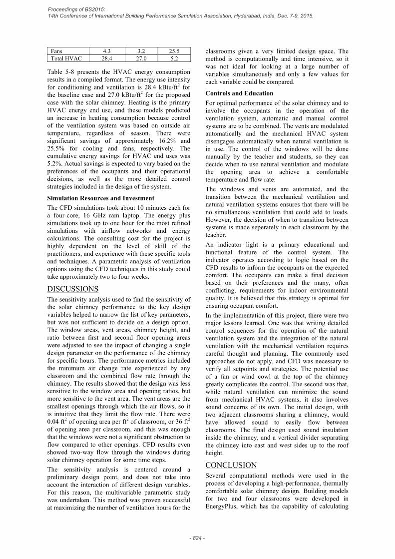
Fans 4.3 3.2 25.5 Total HVAC 28.4 27.0 5.2
Table 5-8 presents the HVAC energy consumption results in a compiled format. The energy use intensity for conditioning and ventilation is 28.4 kBtu/ft2 for the baseline case and 27.0 kBtu/ft2 for the proposed case with the solar chimney. Heating is the primary HVAC energy end use, and these models predicted an increase in heating consumption because control of the ventilation system was based on outside air temperature, regardless of season. There were significant savings of approximately 16.2% and 25.5% for cooling and fans, respectively. The cumulative energy savings for HVAC end uses was 5.2%. Actual savings is expected to vary based on the preferences of the occupants and their operational decisions, as well as the more detailed control strategies included in the design of the system.
Simulation Resources and Investment The CFD simulations took about 10 minutes each for a four-core, 16 GHz ram laptop. The energy plus simulations took up to one hour for the most refined simulations with airflow networks and energy calculations. The consulting cost for the project is highly dependent on the level of skill of the practitioners, and experience with these specific tools and techniques. A parametric analysis of ventilation options using the CFD techniques in this study could take approximately two to four weeks.
DISCUSSIONS The sensitivity analysis used to find the sensitivity of the solar chimney performance to the key design variables helped to narrow the list of key parameters, but was not sufficient to decide on a design option. The window areas, vent areas, chimney height, and ratio between first and second floor opening areas were adjusted to see the impact of changing a single design parameter on the performance of the chimney for specific hours. The performance metrics included the minimum air change rate experienced by any classroom and the combined flow rate through the chimney. The results showed that the design was less sensitive to the window area and opening ratios, but more sensitive to the vent area. The vent areas are the smallest openings through which the air flows, so it is intuitive that they limit the flow rate. There were 0.04 ft2 of opening area per ft2 of classroom, or 36 ft2 of opening area per classroom, and this was enough that the windows were not a significant obstruction to flow compared to other openings. CFD results even showed two-way flow through the windows during solar chimney operation for some time steps. The sensitivity analysis is centered around a preliminary design point, and does not take into account the interaction of different design variables. For this reason, the multivariable parametric study was undertaken. This method was proven successful at maximizing the number of ventilation hours for the
classrooms given a very limited design space. The method is computationally and time intensive, so it was not ideal for looking at a large number of variables simultaneously and only a few values for each variable could be compared.
Controls and Education For optimal performance of the solar chimney and to involve the occupants in the operation of the ventilation system, automatic and manual control systems are to be combined. The vents are modulated automatically and the mechanical HVAC system disengages automatically when natural ventilation is in use. The control of the windows will be done manually by the teacher and students, so they can decide when to use natural ventilation and modulate the opening area to achieve a comfortable temperature and flow rate. The windows and vents are automated, and the transition between the mechanical ventilation and natural ventilation systems ensures that there will be no simultaneous ventilation that could add to loads. However, the decision of when to transition between systems is made seperately in each classroom by the teacher. An indicator light is a primary educational and functional feature of the control system. The indicator operates according to logic based on the CFD results to inform the occupants on the expected comfort. The occupants can make a final decision based on their preferences and the many, often conflicting, requirements for indoor environmental quality. It is believed that this strategy is optimal for ensuring occupant comfort. In the implementation of this project, there were two major lessons learned. One was that writing detailed control sequences for the operation of the natural ventilation system and the integration of the natural ventilation with the mechanical ventilation requires careful thought and planning. The commonly used approaches do not apply, and CFD was necessary to verify all setpoints and strategies. The potential use of a fan or wind cowl at the top of the chimney greatly complicates the control. The second was that, while natural ventilation can minimize the sound from mechanical HVAC systems, it also involves sound concerns of its own. The initial design, with two adjacent classrooms sharing a chimney, would have allowed sound to easily flow between classrooms. The final design used sound insulation inside the chimney, and a vertical divider separating the chimney into east and west sides up to the roof height.
CONCLUSION Several computational methods were used in the process of developing a high-performance, thermally comfortable solar chimney design. Building models for two and four classrooms were developed in EnergyPlus, which has the capability of calculating
Proceedings of BS2015: 14th Conference of International Building Performance Simulation Association, Hyderabad, India, Dec. 7-9, 2015.
- 824 -

inter-zonal airflow taking into account wind speed and direction and buoyancy induced pressure differentials. The models matched the proposed constructions, operations and geometry of the classrooms in the Powell Elementary School Building C project. A sensitivity analysis looked at several variables, and the key variables were studied with a simple multi-variable optimization that considered the total annual performance of the system rather than focusing on individual time steps. CFD was used to assess comfort for design flowrates and gather data for the controls system. The controls were developed to focus on occupant control in each classroom, to increase the occupant satisfaction and educational potential. However, an indicator light based on logic informed by the detailed CFD simulations acted as a reminder and easy signal of comfortable natural ventilation conditions. Finally, the solar chimney was predicted by an energy model to save up to 5.2% of the total HVAC energy consumption for the space. This is the total potential savings, and while the actual control of the natural ventilation system cannot be easily simulated, it is likely to reduce the actual savings margin.
REFERENCES Chung, L. P., Ahmad, M. H. B., Ossen, D. R.,
Hamid, M. 2014. Application of CFD in prediction of indoor building thermal performance as an effective pre-design tool towards sustainability, World Applied Sciences Journal, 30(30 A), 269–279.
Dols, W. S., Emmerich, S. J., & Polidoro, B. J. 2012. LoopDA 3.0 – Natural Ventilation Design and Analysis Software User Guide, National Institute of Standards and Technology Technical Note 1735, U.S.A.
EnergyPlus. 2014. Input Output Reference, Department of Energy, U.S.A.
Jianliu, X., Weihua, L. 2013. Study on solar chimney used for room natural ventilation in Nanjing, Energy and Buildings, 66, 467–469.
Khanal, R., Lei, C. 2011. Solar chimney - A passive strategy for natural ventilation, Energy and Buildings, 43(8), 1811-1819.
Khanal, R., Lei, C. 2014. An experimental investigation of an inclined passive wall solar chimney for natural ventilation, Solar Energy, 107, 461–474.
Lal, S. 2014. Experimental, CFD simulation and parametric studies on modified solar chimney for building ventilation, Applied Solar Energy, 50(1), 37–43.
Tan, A. Y. K., Wong, N. H. 2014. Influences of ambient air speed and internal heat load on the performance of solar chimney in the tropics, Solar Energy, 102, 116–125.
Proceedings of BS2015: 14th Conference of International Building Performance Simulation Association, Hyderabad, India, Dec. 7-9, 2015.
- 825 -