performance analysis of group paging for machine-type ... · performance analysis of group paging...
TRANSCRIPT
IEEE TRANSACTIONS ON VEHICULAR TECHNOLOGY, VOL. 62, NO. 7, SEPTEMBER 2013 3371
Performance Analysis of Group Paging forMachine-Type Communications in LTE Networks
Chia-Hung Wei, Ray-Guang Cheng, Senior Member, IEEE, and Shiao-Li Tsao, Member, IEEE
Abstract—Machine-type communication (MTC) is a crucial ser-vice for next-generation cellular networks. Mass access to thenetwork by MTC devices may result in the overload of radio accessnetworks (RANs) and degrade the service quality of human-to-human communication. Group paging is one of the mechanismsproposed to alleviate the RAN-overload problem. This paperpresents an analytical model based on a recursive contending-users estimation (RCE) method proposed in the literature to derivethe performance metrics of collision probability, access successprobability, average access delay, statistics of preamble transmis-sions, statistics of access delay, and utilization of random-accessopportunities (RAOs) for group paging with various combinationsof group sizes and reserved radio resources in a paging accessinterval. The optimal group size and required RAOs are subse-quently derived based on the given target access success probabil-ity. Numerical results demonstrate that the proposed model canaccurately estimate the performance of group paging.
Index Terms—Group paging, machine-type communications(MTC), overload control, random access.
I. INTRODUCTION
MACHINE-TYPE communication (MTC), which is alsoknown as machine-to-machine communication (M2M)
in the IEEE 802.16 Working Group, is a new service defined bythe Third-Generation Partnership Project (3GPP) to facilitatemachines communicating with each other over current cellularnetworks [2]. MTC usually involves a large number of MTCdevices to support a wide range of applications, such as smartgrid, road security, and consumer electronic devices. However,concurrent access to a radio network by mass MTC devicesmay result in intolerable delays, packet loss, or even serviceunavailability to current human-to-human (H2H) communica-tion services. Hence, proper overload control mechanisms arerequired to guarantee network availability and quality of H2Hservices under heavy MTC load [2].
Overload control of an uplink random-access channel(RACH) in a radio access network (RAN) is one of the principle
Manuscript received March 13, 2012; revised August 23, 2012 andNovember 8, 2012; accepted December 18, 2012. Date of publication March 7,2013; date of current version September 11, 2013. This work was supportedin part by the National Science Council, Taiwan, under Contract No. NSC101-2219-E-011-005, NSC 101-3113-P-011-003, NSC 101-2219-E-009-026,and NSC 102-2218-E-011-002. The review of this paper was coordinated byProf. V. W. S. Wong.
C.-H. Wei and R.-G. Cheng are with the Department of Electronic andComputer Engineering, National Taiwan University of Science and Technology,Taipei 106, Taiwan (e-mail: [email protected]).
S.-L. Tsao is with the Department of Computer Science, National ChiaoTung University, Hsinchu 300, Taiwan.
Color versions of one or more of the figures in this paper are available onlineat http://ieeexplore.ieee.org.
Digital Object Identifier 10.1109/TVT.2013.2251832
working items for 3GPP Long-Term Evolution (LTE) [2].The purpose of RAN-overload control is to avoid RAN over-load when mass MTC devices simultaneously contend forthe RACH. From the perspective of the way MTC traffic isgenerated, RAN-overload control schemes can be categorizedinto push- and pull-based approaches [3]. In the push-basedapproach, MTC traffic is pushed from MTC devices to the net-work without any restriction until RAN overload is detected. Inthe pull-based approach, MTC traffic is pulled by the network,and thus, the network may properly control the MTC traffic loadthrough paging and, thus, prevents RAN overload.
Access class barring (ACB), separated RACH resources forMTC, dynamic allocation of RACH resource, MTC-specificbackoff scheme, and slotted access are examples of push-basedRAN-overload control schemes [2]. In the ACB scheme, thenetwork separates the MTC traffic into several access classesand assigns an ACB factor to each MTC access class. Each cellcan control the channel access probability of a specific MTCaccess class by setting the ACB factor. In the separated RACHscheme, the network reserves dedicated RACH resources forthe H2H and MTC devices to provide them with distinct accesscollision probabilities. In the dynamic allocation of the RACHresource scheme, the network dynamically allocates additionalRACH resources for the MTC devices based on the predictedaccess load of MTC devices. The MTC-specific backoff schemedelays the random-access reattempts/attempts of MTC devicesby assigning an MTC-specific random backoff procedure. Inthe slotted-access scheme, each MTC device is associated withdedicated access cycles/slots (similar to paging cycles/slots)through its identity. Each MTC device can transmit the random-access attempt only at its random-access slot. The advantagesand disadvantages of various push-based RAN-overload controlschemes are summarized in [4].
Paging and group paging are potential pull-based RAN-overload control schemes [5]. In LTE, a downlink pagingchannel is defined to transmit paging information to user equip-ment (UE), informing UE on system information changes andemergency notifications. The network may transmit a pagingmessage to activate a specific UE at the UE’s paging occasion.The paging occasion of each UE is determined according to itsUE identity. The current paging mechanism that was originallydesigned for H2H services can only page up to 16 devices witha single paging message, and only two paging occasions areavailable per 10-ms radio frame [5]. Therefore, a base station(BS) must transmit multiple paging messages over a long periodto activate a large number of MTC devices. Therefore, a group-paging mechanism that uses a single group-paging message toactivate a group of MTC devices is proposed to address this
0018-9545 © 2013 IEEE

3372 IEEE TRANSACTIONS ON VEHICULAR TECHNOLOGY, VOL. 62, NO. 7, SEPTEMBER 2013
issue [2]. In group paging, an MTC device is assigned by aunique group identity (GID) after camping on a network andjoining a group. All of the MTC devices in a group listen tothe same paging channel at the same paging occasion derivedfrom the GID [5]. The group of MTC devices shall simulta-neously perform the standard LTE random-access procedureto access the network when they find their GID in a group-paging message. The MTC devices with random access thatfail shall follow the standard LTE random backoff procedure toretransmit their random-access attempts during a paging accessinterval until the retry limitation exceeds. Note that the networkmay use the group-paging message to notify MTC devices ofthe paging access interval and the dedicated random-accessresources reserved for group paging.
The first simulation study of group paging is given in [6].The main performance metrics specified in 3GPP TR 37.868[2], which include collision probability, access success prob-ability, statistics of number of preamble transmissions, andstatistics of access delay, were investigated. The preliminarystudy showed that group paging is a promising solution forRAN-overload control. However, it lacks a general rule forLTE operators to determine the proper number of reservedrandom-access resources and the group size. This paper aimsto develop an analytical model to investigate the performanceof group paging and to suggest related parameters. The an-alytical model needs to consider all of the implementationconstraints specified in LTE [2]. The implementation con-straints include the LTE random backoff procedure; the lim-ited capacity of the downlink access grant channel, whichresults in failed random access even if the random-accessattempts are not collided; the maximum number of retrans-missions for failed random-access attempts; the exponentiallaw for the power-ramping effect, which results in a time-varying detection probability for the random-access attempts;and the transmission delay of the message part considering theeffect of a hybrid automatic retransmission request (HARQ)procedure.
The random-access architecture of LTE is similar to a mul-tichannel slotted ALOHA system. Much research has beendevoted to the slotted ALOHA system in single-channel [7], [8]or multichannel slotted systems [9]–[16]. In [7], the throughputof single-channel slotted ALOHA systems as a function of aconstant offered load was presented. In [8], the relationshipbetween the throughput and the average access delay of a finite-user single-channel slotted ALOHA system was investigated.For multichannel slotted ALOHA systems, the performancemetrics of the throughput [9], [10], [13], average access delay[11]–[15], and collision and success probabilities [16] werealso discussed. The purposes of these studies were to reduceaccess delay [9], adjust the design parameters to stabilize thechannels [10]–[12], maximize the throughput [13], [14], orrealize the tradeoff between the average throughput and theaverage access delay [15]. A finite-population system wasconsidered in [11] and [12]. In [11], the stability and delay offinite-user slotted ALOHA systems with multipacket receptionwere investigated. In [12], Jelenkovic and Tan showed that thevariability of packet sizes results in power law delays for finite-population ALOHA systems. In [14], Zhou et al. presented
closed-form expressions of throughput and access delay fororthogonal frequency-division multiple-access systems. Theanalysis was derived based on an assumption of a constantsuccessful transmission probability. The collision and successprobabilities defined from the perspective of a user and a RACHin LTE systems were discussed in [16]. The effect of the randombackoff procedure in slotted ALOHA systems was consideredin [7]–[9], [13], [14], and [16]. The effect of the time-varyingpreamble detection probability due to a fading channel wasconsidered in [7]. The impact of the backoff window size on theaverage access delay was discussed in [8]. Access randomnessin the time domain was considered in [8] and [9], access ran-domness in the frequency domain was considered in [13], andaccess randomness in the time, code, and frequency domainswas considered in [14] and [16]. Most of the aforementionedstudies focus on the uniform backoff policy. Both the binaryexponential and uniform backoff policies were considered in[14]. The constraint of the maximum number of retransmis-sions in the random-access procedure was considered in [13]and [14].
Most of the performance evaluations of ALOHA systemsfocused on average value (throughput and/or access delay)analysis [9]–[11], [13], and the distributional property was onlyaddressed in [12]. Existing studies normally assumed that newpacket arrivals in a slot time follow a Bernoulli distribution[10], [11] or a Poisson distribution [7], [9], [12]–[15] with aconstant rate, and thus, the combined rate of new and retrans-mission packets in a slot is a constant. In group paging, thenumber of MTC devices to be paged is known, and the MTCdevices access the network in a highly synchronized manneronce they are paged. However, the random-access attempts ineach random-access slot are not fixed because no new arrival isgenerated and the number of MTC devices gradually decreasesif any device successfully access the RACH. Moreover, theanalytical model has to consider the system environment (forexample, the power-ramping effect) and the distributional prop-erties related performance metrics (that is, statistics of preambletransmissions and access delay) of LTE. Therefore, currentanalytical models cannot be directly applied to the performanceanalysis of group paging in LTE networks. This paper presentsan analytical model to derive the performance metrics of grouppaging by considering all of the parameters defined in the LTErandom-access procedure [17]. Similar to existing approaches,we use the known paging group size and the Poisson approxi-mation model [1] to estimate the number of success and failed(or collided) devices in the first random-access slot. Differentfrom current approaches, the numbers of contending devicesin the successive random-access slots are then individuallyderived as a function of the number of failed devices, thetime-domain backoff parameters, the limited capacity of thedownlink access grant channel, and the time-varying detectingprobability. The performance metrics of group paging are thenderived based on the estimated number of success and faileddevices obtained from all random-access slots. The remainderof this paper is organized as follows: The system model andthe analytical model are described in Section II. Section IIIpresents the numerical results. Finally, conclusions are offeredin Section IV.

WEI et al.: PERFORMANCE ANALYSIS OF GROUP PAGING FOR MTC IN LTE NETWORKS 3373
Fig. 1. Timing diagram of physical random-access transmission of LTE.
II. SYSTEM MODEL
This study considers a group of M MTC devices in a pagingarea containing K cells in an LTE network. Without loss ofgenerality, we considered a case where the MTC devices areuniformly distributed in K cells, and thus, each cell has M/KMTC devices. It is assumed that each BS in the paging areareserves an amount of R dedicated random-access resourcesand sends a group-paging message containing a GID to pagethe M/K MTC devices simultaneously. Once the group-pagingmessage is received, all M/K MTC devices follow the standardLTE random-access procedure to establish connections with theBS. The performance of random access during a paging accessinterval will be investigated. The paging access interval ofgroup paging starts from the first random-access slot and endsat the Imaxth random-access slot, where Imax is the number ofrandom-access slots reserved for group paging. Note that Imax
depends on the maximum number of preamble transmissionsof the random-access procedure and will be derived later in thispaper.
Fig. 1 shows time-frequency mapping [18] and the timingdiagram of physical random-access transmission of LTE. InLTE, time is divided into fix-length radio frames. Each radioframe consists of multiple subframes. Random-access trans-missions are restricted to specific subframes [16], which arereferred to as random-access slots in the rest of this paper.
In LTE, the random-access resource is determined in termsof random-access opportunities (RAOs). The total number ofRAOs provided by a BS in a random-access slot is equal tothe number of frequency bands in each random-access slotmultiplied by the number of random-access preambles [17]. InLTE, one access window of length TRA per TRA_REP period isallocated for random access [17], as shown in Fig. 1. TRA_REP
is the interval between two successive random-access slotsand can be obtained from the physical random access channel(PRACH) configuration index announced by the BS. For exam-ple, TRA_REP = 5 radio frames [19] if PRACH configurationindex 6 is used [2].
The timing diagram shown in Fig. 1 shows the behaviorof an MTC device receiving a group-paging message. In thispaper, the time axis starts from the first random-access slot inwhich all MTC devices send their first random-access attemptsimmediately after receiving the group-paging message from theBS. Hence, the time of the ith random-access slot is (i− 1)×TRA_REP, as shown in Fig. 1. Before going into the details,the LTE random-access procedure is first elaborated upon, asfollows.
A. LTE Random-Access Procedure
Fig. 2 shows the LTE two-step random-access procedure[17], which separates the transmission of the random-access

3374 IEEE TRANSACTIONS ON VEHICULAR TECHNOLOGY, VOL. 62, NO. 7, SEPTEMBER 2013
Fig. 2. Two-step random access (the numbers describe different events during a random-access procedure) [21].
preamble and the associated signaling messages (Msg 3 andMsg 4) for a connection setup. The preamble is transmittedthrough a common channel shared by multiple UEs, and thesignaling messages are transmitted in a dedicated channelspecifically reserved for UE. In the first step, UE synchronizesto the downlink timing [(1) in Fig. 2], randomly selects arandom-access preamble from a group of preambles reservedfor the RACH, and transmits the random-access preamble in arandomly chosen random-access slot and a frequency band (2).The BS correlates the received signal with the set of possiblesequences in a cell and transmits a response message indicatingthe detected preamble(s) (3). Each response message carries amedium access control (MAC) header and one or more MACrandom-access responses (RARs). The MAC header may carrya backoff indicator (BI) (unit: subframe) to indicate the backoffparameter values for the collided or undetected UEs. In LTE,the range of BI is from 0 to 960 subframes [17]. Each RARcarries the identity (ID) of the preamble selected by the UE, theinformation to be used by the UE to adjust the uplink timing,and a dedicated uplink resource reserved for the UE to transmitthe message [17].
Let TRAR be the processing time required by the BS todetect the transmitted preambles (unit: subframe), WRAR be thelength of the random-access-response window (unit: subframe),WBO be the length of the backoff window (unit: subframe)(WBO = BI + 1), and NPTmax be the maximum number ofpreamble transmissions. As shown in Fig. 1, the random-access-response window starts at the end of the preamble trans-mission plus TRAR [17] subframes, and the backoff windowstarts at the end of the random-access-response window. TheUE should perform random backoff and retransmit its random-access attempt if it does not receive the response messagewithin WRAR. For each retransmitted random-access attempt,the UE must randomly choose a backoff counter from zero toBI , ramp up its transmission power, and transmit a newly selec-
ted random-access preamble in the next available random-accessslot when the backoff counter decreases to zero. The processcontinues until NPTmax preamble transmissions are reached.
Once the UE receives the response message from the BS andadjusts its uplink timing, the remaining signaling required forthe connection setup is transmitted on the assigned dedicateduplink resource in a synchronized manner by using the sameprocedures as normal data transmission. Nonadaptive HARQis subsequently enabled to protect the signaling exchange ofthe message. The UE, which successfully receives the RARmessage, must send Msg3 carrying the UE ID and the “radioresource control connection request” message to the BS atthe radio resource assigned by the BS [(4) in Fig. 2]. Inresponse, the BS sends an HARQ acknowledgment (ACK)or negative-acknowledgment (NACK) after THARQ subframes.The BS waits for TA_M4 subframes and transmits Msg4 (8)after it replies an ACK indicating that Msg3 is successfullyreceived (7). In contrast, the UE waits for TM3 subframes andretransmits Msg3 (6) if it receives an NACK (5). Similarly, theUE waits for THARQ subframes and sends an ACK to the BSif Msg4 is successfully received (11). The BS waits for TM4
subframes and retransmits Msg4 (10) if it does not receive anACK for Msg4 (9). The HARQ retransmission of Msg3 andMsg4 can be up to NHARQ times. The UE starts/restarts acontention resolution timer TCR (unit: subframes) whenever ittransmits Msg3. The UE declares a random-access failure andreverts to step 1 to retransmit its random-access attempt if thecontention resolution timer expires. Note that Msg 3 and Msg 4are used for carrying connection setup signaling messages andfor contention resolution. In some cases, the BS may have achance to decode the same preamble transmitted by multipleUE and reply a response message. The UE will transmit itsown Msg3 on the same dedicated resource and then realizethe random-access failure after the expiry of the contentionresolution timer.

WEI et al.: PERFORMANCE ANALYSIS OF GROUP PAGING FOR MTC IN LTE NETWORKS 3375
TABLE IRANDOM-ACCESS RELATED SYSTEM PARAMETERS
Let R be the number of RAOs reserved by the BS ineach random-access slot, NRAR be the maximum number ofRARs that can be carried in a response message, NUL be themaximum number of MTC devices that can be acknowledgedwithin the RAR window (NUL = NRAR ×WRAR), pf be theHARQ retransmission probability for Msg3 and Msg4, andpn be the preamble detection probability of the nth pream-ble transmission (1 ≤ n ≤ NPTmax). In LTE, pn is expressedas [2]
pn = 1 − 1en
, (1)
which models the power-ramping effect. Table I summarizesthe random-access related system parameters defined in [2] andused in this paper.
When the group-paging message is received, all MTC de-vices should transmit their first preambles at the first random-access slot. The MTC devices should perform backoff andretransmit a new preamble up to (NPTmax − 1) times if therandom access fail. For each preamble transmission, each MTCdevice may spend up to (TRAR +WRAR +WBO) subframesbefore retransmitting a new preamble. Hence, the number ofrandom-access slots reserved for group paging (Imax) is ex-pressed as
Imax = 1 + (NPTmax − 1)×⌈TRAR +WRAR +WBO
TRA_REP
⌉.
(2)
TABLE IIVARIABLES USED IN THE ANALYTICAL MODEL
The paging access interval of group paging starts from the firstrandom-access slot and ends at the Imaxth random-access slot.In other words, the length of the paging access interval is 1 +(Imax − 1)× TRA_REP subframes.
B. Analytical Model
In the following, an analytical model is presented to estimatethe numbers of contending, success, and failed MTC devices ineach random-access slot during a paging access interval. Theperformance metrics of group paging are then derived basedon the estimated number of MTC devices. Table II summarizesthe variables to be used in the proposed analytical model. Let

3376 IEEE TRANSACTIONS ON VEHICULAR TECHNOLOGY, VOL. 62, NO. 7, SEPTEMBER 2013
Mi[n] be the number of contending MTC devices that transmitthe nth preambles at the ith random-access slot, Mi,S [n] be thenumber of success MTC devices that transmit the nth pream-bles at the ith random-access slot and successfully finish thepreamble transmission (that is, the preambles are not collided,detected by the BS, and indicated in RARs), and Mi,F [n] be thenumber of failed MTC devices that transmit the nth preamblesat the ith random-access slot but do not finish the preambletransmission (that is, the preambles are collided; not collidedand not detected by the BS; or not collided, detected by the BS,and not indicated in RARs). Let Mi be the total number of MTCdevices that transmit their preambles in the ith random-accessslot, which is the summation of all contending MTC devices.That is,
Mi =
NPTmax∑n=1
Mi[n]. (3)
In [1], we showed that the number of MTC devices withpreamble transmissions that have not collided for Mi MTCdevices and R RAOs at the ith random-access slot can beapproximated by Mie
−Mi/R. Among these, Mi[n]/Mi ofthe MTC devices transmit their nth preambles that are de-tected with a probability of pn. Therefore, Mi[n]e
−Mi/RpnMTC devices are detected. All of the detected MTC devicescan receive the acknowledgment messages if the total num-ber of detected MTC devices does not exceed NUL (i.e.,∑NPTmax
n=1 Mi[n]e−Mi/Rpn ≤ NUL). Otherwise, the BS ran-
domly sends the acknowledgment messages to NUL detectedMTC devices. In this case, the number of MTC devices thatcan receive the acknowledgment messages is proportional tothe number of detected MTC devices that belong to the samecategory. Hence, Mi,S [n] can be determined as
Mi,S [n]=
⎧⎪⎪⎪⎪⎪⎪⎪⎨⎪⎪⎪⎪⎪⎪⎪⎩
Mi[n]e−Mi
R pn, ifNPTmax∑n=1
Mi[n]
×e−MiR pn ≤ NUL
Mi[n]e−Mi
R pn
NPTmax∑n=1
Mi[n]e−Mi
R pn
NUL, otherwise.
(4)
The number of failed MTC devices is equal to the number ofcontending MTC devices minus the number of success MTCdevices. That is
Mi,F [n]
= Mi[n]−Mi,S [n]
=
⎧⎪⎪⎪⎪⎪⎪⎪⎪⎪⎨⎪⎪⎪⎪⎪⎪⎪⎪⎪⎩
Mi[n](
1−e−MiR pn
), if
NPTmax∑n=1
Mi[n]e−Mi
R
×pn≤NUL
Mi[n]
⎛⎜⎜⎝1− pn
NPTmax∑n=1
Mi[n]pn
⎞⎟⎟⎠
×NUL, otherwise.
(5)
Note that Mi,S [n] is the number of success MTC devicesthat transmit the nth preambles at the ith random-access slotand successfully finish the preamble transmission. These MTCdevices will immediately transmit the messages through thededicated channel indicated in the RAR.
The number of MTC devices that transmit the nth preamblesat the ith random-access slot, i.e., Mi[n], is expressed as
Mi[n] =
Kmax∑k=Kmin
αk,iMk,F [n− 1]
+
Jmax∑j=Jmin
βj,ipe,MSGMj,S [n− 1]
≈Kmax∑
k=Kmin
αk,iMk,F [n− 1]. (6)
Equation (6) comprises two parts: MTC devices with preambletransmissions that failed and those with message transmissionsthat failed. The first part of (6) (Mk,F [n− 1]) represents asituation where the MTC devices transmit the (n− 1)th pream-bles at the kth random-access slot, but they fail to completethe preamble transmission. Among these MTC devices withpreamble transmissions that failed, ak,i of them will performrandom backoff and retransmit the nth preambles at the ithrandom-access slot. Kmin and Kmax denote the minimal andmaximal values of k, respectively. Hence, we accumulate thepossible cases of k from Kmin to Kmax to obtain the numberof MTC devices with preamble transmissions that failed. Thesecond part of (6) (Pe,MSGMj,S [n− 1]) denotes a situationwhere the MTC devices transmit the (n− 1)th preambles atthe jth random-access slot, finish the preamble transmission,and fail in messages part (Msg 3 and Msg 4) transmissionat error probability Pe,MSG. Among these MTC devices withmessage transmissions that failed, βj,i of them will performrandom backoff and retransmit the nth preambles at the ithrandom-access slot. Jmin and Jmax denote the minimal andmaximal values of j, respectively. Hence, we accumulate thepossible cases of J from Jmin to Jmax to obtain the number ofMTC devices with preamble transmissions that failed. Note thatmessage transmission is failed if Mgs3 transmission exceedsNHARQ times, or Msg3 transmission is a success but Mgs4transmission exceeds NHARQ times. Therefore, Pe,MSG can bederived as
Pe,MSG = pNHARQ
f +
NHARQ−1∑j=0
pjf (1 − pf )pNHARQ
f . (7)
In LTE, NHARQ is a constant of 5 [17], pf = 0.1 is assumedin [2], and βj,i ≤ 1, which obtains a small value for Pe,MSG.Hence, the second term in (6) is negligible.ak,i, Kmin, and Kmax in (6) can be derived based on the
timing diagram given in Fig. 1. The MTC device, in whichpreamble transmission is failed at the kth random-access slot,may retransmit a new preamble at the ith random-accessslot only if the backoff interval of the kth random-accessslot is overlapped with the transmission interval of the ith

WEI et al.: PERFORMANCE ANALYSIS OF GROUP PAGING FOR MTC IN LTE NETWORKS 3377
random-access slot. Therefore, ak,i is the portion of thebackoff interval of the kth random-access slot that overlapswith the transmission interval of the ith random-access slot(k < i). As shown in Fig. 1, the MTC devices that trans-mit their preambles at the kth random-access slot at time(k − 1)× TRA_REP will recognize their random-access failureafter (TRAR +WRAR) subframes. Each failed MTC devicestarts random backoff at time (k − 1)× TRA_REP + (TRAR +WRAR) + 1. Therefore, the backoff interval of the kth random-access slot starts from time (k − 1)× TRA_REP + TRAR +WRAR + 1 and ends at time (k − 1)× TRA_REP + TRAR +WRAR +WBO. The MTC devices transmit their preambles atthe ith random-access slot if their backoff counters reach zeroduring the interval between the (i− 1)th random-access slotand the ith random-access slot. Therefore, the transmissioninterval of the ith random-access slot is [(i− 2)× TRA_REP +1, (i− 1)× TRA_REP].
The minimal value of k (Kmin) is obtained when theright boundary of the kth random-access slot backoff inter-val reaches the left boundary of the ith random-access slottransmission interval (i.e., (Kmin − 1)× TRA_REP + TRAR +WRAR +WBO ≥ 1 + (i− 2)× TRA_REP)). Therefore, Kmin
is expressed as
Kmin =
⌈(i− 1) +
1 − (TRAR +WRAR +WBO)
TRA_REP
⌉. (8)
The maximal value of k (Kmax) is obtained when theleft boundary of the kth random-access slot backoff inter-val exceeds the right boundary of the ith random-access slottransmission interval (i.e., (Kmax − 1)× TRA_REP + TRAR +WRAR + 1 ≤ (i− 1)× TRA_REP). Hence
Kmax =
⌊i− TRAR +WRAR + 1
TRA_REP
⌋. (9)
ak,i can be determined based on k in three cases shownon the lower part in Fig. 1. In the first case, the right bound-ary of the backoff interval is within the transmission in-terval (i.e., (i− 2)× TRA_REP + 1 ≤ (k − 1)× TRA_REP +TRAR +WRAR +WBO ≤ (i− 1)× TRA_REP). In this case,Kmin ≤ k ≤ i− (TRAR +WRAR +WBO)/TRA_REP and theoverlapped region start from the left boundary of the trans-mission interval and end at the right boundary of the backoffinterval. In the second case, the transmission interval is fullyoverlapped with the backoff interval; thus, the length of theoverlapped region is TRA_REP. In the third case, the leftboundary of the backoff interval is within the transmission in-terval (i.e., (i− 2)× TRA_REP + 1 ≤ (k − 1)× TRA_REP +TRAR +WRAR + 1 ≤ (i− 1)× TRA_REP). In this case, (i−
1)− (TRAR +WRAR)/TRA_REP ≤ k ≤ Kmax and the over-lapped region start from the left boundary of the backoff inter-val and end at the right boundary of the transmission interval.ak,i is the ratio between the overlapped region and the backoffinterval and is expressed as in (10), shown at the bottom ofthe page.
Initially, all of the M/K MTC devices transmit their firstpreambles at the first random-access slot. Hence, the initialconditions can be set by M1 = M1[1] = M/K and M1[n] = 0for n �= 1. Let i = 1 in (4); therefore, we derive
M1,S [n]=
⎧⎪⎨⎪⎩NUL, if n=1 and M
K e−M/K
R p1≥NUL
MK e−
M/kR p1, if n=1 and M
K e−M/K
R p1<NUL
0, if n �=1.(11)
Let i = 1 in (5), we obtain
M1,F [n]
=
⎧⎪⎨⎪⎩
MK −NUL, if n=1 and M
K e−M/K
R p1≥NUL
MK
(1−e−
M/KR p1
), if n=1 and M
K e−M/K
R p1<NUL
0, if n �=1.
(12)
For i ≥ 2, Mi,S [n], Mi,F [n], and Mi[n] can be recursivelyobtained from (4)–(6), respectively.
C. Performance Metrics
The collision probability, access success probability, statis-tics of number of preamble transmissions, statistics of accessdelay, average access delay, and the utilization of RAOs ob-tained in a paging access interval are chosen as the performancemetrics in this paper to evaluate the performance of grouppaging. The collision probability, i.e., PC , is defined as the ratiobetween the number of occurrences when two or more MTCdevices send random-access attempts with the same preambleand at the same frequency band and the overall number ofRAOs (with or without random-access attempts) reserved bythe BS [2]. That is, PC is the ratio between the total number ofcollided RAOs and the total number of reserved RAOs. In eachrandom-access slot, the number of collided RAOs is equal tothe number of reserved RAOs (R) minus the number of successRAOs (Mie
−Mi/R) and the number of idle RAOs. In [1], it isshown that the number of idle RAOs at the ith random-accessslot can be obtained from a one-shot random access with Mi
MTC devices contending for R RAOs and can be approximatedby Re−Mi/R. The total number of collided RAOs in a paging
αk,i=
⎧⎪⎪⎪⎪⎨⎪⎪⎪⎪⎩
(k−1)×TRA_REP+TRAR+WRAR+WBO−(i−2)×TRA_REP
WBO, if Kmin≤k≤ i− TRAR+WRAR+WBO
TRA_REP
TRA_REP
WBO, if i− TRAR+WRAR+WBO
TRA_REP<k<(i−1)− TRAR+WRAR
TRA_REP
(i−1)×TRA_REP−((k−1)×TRA_REP+TRAR+WRAR)WBO
, if (i−1)− TRAR+WRAR
TRA_REP≤k≤Kmax
0, otherwise
(10)
3378 IEEE TRANSACTIONS ON VEHICULAR TECHNOLOGY, VOL. 62, NO. 7, SEPTEMBER 2013
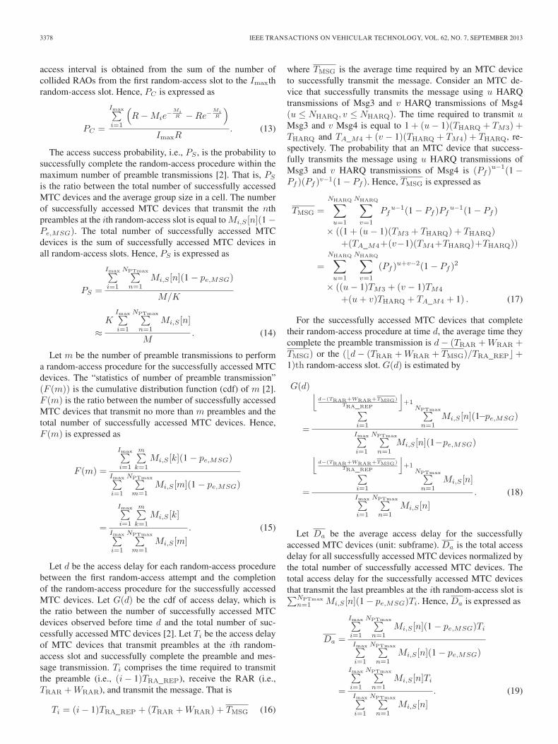
access interval is obtained from the sum of the number ofcollided RAOs from the first random-access slot to the Imaxthrandom-access slot. Hence, PC is expressed as
PC =
Imax∑i=1
(R−Mie
−MiR −Re−
MiR
)
ImaxR. (13)
The access success probability, i.e., PS , is the probability tosuccessfully complete the random-access procedure within themaximum number of preamble transmissions [2]. That is, PS
is the ratio between the total number of successfully accessedMTC devices and the average group size in a cell. The numberof successfully accessed MTC devices that transmit the nthpreambles at the ith random-access slot is equal to Mi,S [n](1 −Pe,MSG). The total number of successfully accessed MTCdevices is the sum of successfully accessed MTC devices inall random-access slots. Hence, PS is expressed as
PS =
Imax∑i=1
NPTmax∑n=1
Mi,S [n](1 − pe,MSG)
M/K
≈K
Imax∑i=1
NPTmax∑n=1
Mi,S [n]
M. (14)
Let m be the number of preamble transmissions to performa random-access procedure for the successfully accessed MTCdevices. The “statistics of number of preamble transmission”(F (m)) is the cumulative distribution function (cdf) of m [2].F (m) is the ratio between the number of successfully accessedMTC devices that transmit no more than m preambles and thetotal number of successfully accessed MTC devices. Hence,F (m) is expressed as
F (m) =
Imax∑i=1
m∑k=1
Mi,S [k](1 − pe,MSG)
Imax∑i=1
NPTmax∑m=1
Mi,S [m](1 − pe,MSG)
=
Imax∑i=1
m∑k=1
Mi,S [k]
Imax∑i=1
NPTmax∑m=1
Mi,S [m]
. (15)
Let d be the access delay for each random-access procedurebetween the first random-access attempt and the completionof the random-access procedure for the successfully accessedMTC devices. Let G(d) be the cdf of access delay, which isthe ratio between the number of successfully accessed MTCdevices observed before time d and the total number of suc-cessfully accessed MTC devices [2]. Let Ti be the access delayof MTC devices that transmit preambles at the ith random-access slot and successfully complete the preamble and mes-sage transmission. Ti comprises the time required to transmitthe preamble (i.e., (i− 1)TRA_REP), receive the RAR (i.e.,TRAR +WRAR), and transmit the message. That is
Ti = (i− 1)TRA_REP + (TRAR +WRAR) + TMSG (16)
where TMSG is the average time required by an MTC deviceto successfully transmit the message. Consider an MTC de-vice that successfully transmits the message using u HARQtransmissions of Msg3 and v HARQ transmissions of Msg4(u ≤ NHARQ, v ≤ NHARQ). The time required to transmit uMsg3 and v Msg4 is equal to 1 + (u− 1)(THARQ + TM3) +THARQ and TA_M4 + (v − 1)(THARQ + TM4) + THARQ, re-spectively. The probability that an MTC device that success-fully transmits the message using u HARQ transmissions ofMsg3 and v HARQ transmissions of Msg4 is (Pf )
u−1(1 −Pf )(Pf )
v−1(1 − Pf ). Hence, TMSG is expressed as
TMSG =
NHARQ∑u=1
NHARQ∑v=1
Pfu−1(1 − Pf )Pf
u−1(1 − Pf )
× ((1 + (u− 1)(TM3 + THARQ) + THARQ)
+(TA_M4+(v−1)(TM4+THARQ)+THARQ))
=
NHARQ∑u=1
NHARQ∑v=1
(Pf )u+v−2(1 − Pf )
2
× ((u− 1)TM3 + (v − 1)TM4
+(u+ v)THARQ + TA_M4 + 1) . (17)
For the successfully accessed MTC devices that completetheir random-access procedure at time d, the average time theycomplete the preamble transmission is d− (TRAR +WRAR +TMSG) or the (�d− (TRAR +WRAR + TMSG)/TRA_REP�+1)th random-access slot. G(d) is estimated by
G(d)
=
⌊d−(TRAR+WRAR+TMSG)
TRA_REP
⌋+1∑
i=1
NPTmax∑n=1
Mi,S [n](1−pe,MSG)
Imax∑i=1
NPTmax∑n=1
Mi,S [n](1−pe,MSG)
=
⌊d−(TRAR+WRAR+TMSG)
TRA_REP
⌋+1∑
i=1
NPTmax∑n=1
Mi,S [n]
Imax∑i=1
NPTmax∑n=1
Mi,S [n]
. (18)
Let Da be the average access delay for the successfullyaccessed MTC devices (unit: subframe). Da is the total accessdelay for all successfully accessed MTC devices normalized bythe total number of successfully accessed MTC devices. Thetotal access delay for the successfully accessed MTC devicesthat transmit the last preambles at the ith random-access slot is∑NPTmax
n=1 Mi,S [n](1 − pe,MSG)Ti. Hence, Da is expressed as
Da =
Imax∑i=1
NPTmax∑n=1
Mi,S [n](1 − pe,MSG)Ti
Imax∑i=1
NPTmax∑n=1
Mi,S [n](1 − pe,MSG)
=
Imax∑i=1
NPTmax∑n=1
Mi,S [n]Ti
Imax∑i=1
NPTmax∑n=1
Mi,S [n]
. (19)

WEI et al.: PERFORMANCE ANALYSIS OF GROUP PAGING FOR MTC IN LTE NETWORKS 3379
Finally, the utilization of RAOs (U) is defined as the ratio be-tween the total number of successfully accessed MTC devicesand the total number of reserved RAOs. The total number ofsuccessfully accessed MTC devices in the ith random-accessslot is
∑NPTmax
n=1 Mi,S [n](1 − pe,MSG). U is expressed as
U =
Imax∑i=1
NPTmax∑n=1
Mi,S [n](1 − pe,MSG)
ImaxR
≈
Imax∑i=1
NPTmax∑n=1
Mi,S [n]
ImaxR. (20)
III. NUMERICAL RESULTS
Computer simulations were conducted on top of a C-basedsimulator to verify the effectiveness of the proposed analyticalmodel. The simulations were developed based on a Monte Carloapproach. In the simulations, each point represented the averagevalue of 107 samples. We used a computer equipped with anIntel Core2 Quad central processing unit, a Q9500 2.83-GHzprocessor, and 6-GB random-access memory. The time used forcalculating the performance metrics in all cases was less than1 ms. Each sample was obtained by performing group pagingin a paging access interval. In group paging, we may adjustdesign parameters of the average group size per cell (M/K),the reserved RAOs per random-access slot (R), the maximumnumber of preamble transmission (NPTmax), and the backoffwindow size (WBO) to meet the service quality constraints ofthe access success probability (PS), the average access delay(Da), and/or the collision probability (PC). For simplicity,WBO was fixed in all of the simulations.
In the simulations, M/K MTC devices are assumed to initi-ate all random-access attempts. The background traffic causedby Poisson-distributed H2H UEs at an average rate (λ) of 0,8, and 128 calls/s is considered [2]. The RACH parametersdefined in [2, Tab. 2.2.1.1] and the processing latency specifiedin Table B.1.1.1-1 of TR 36.912 [20] were used as a baselinein the simulations. The settings of the parameters used in thesimulation are summarized in Table I.
Two scenarios were investigated. Scenario I was used toverify the accuracy of the analytical model. We considered acase where a BS reserves 54 RAOs in each random-access slot(R = 54) to page a group size of 10–1000 MTC devices percell (M/K = 10 to 1000) with or without H2H traffic, andthe results are shown in Figs. 3–7. Different values of R wereinvestigated, but the results are not shown in the figures. Theresults show that the proposed analytical model can accuratelyestimate the performance metrics of group paging for variouscombinations of M/K, R, and NPTmax. Scenario II wasdesigned to study the effect of the design parameters and thetradeoffs among design strategies according to the given servicequality constraints. Based on this study, a BS can properlyselect the design parameters of R and NPTmax to minimize thetotal number of reserved RAOs according to the target groupsize (M/K) and the specified service quality constraints (PS).The results are shown in Figs. 8–12.
Fig. 3. Collision probability.
Fig. 4. Access success probability.
Fig. 5. Average access delay.
Fig. 6. CDF of preamble transmission.
In Scenario I, the analytical and simulation results of PC ,PS , Da, F (m), and G(d) are shown in Figs. 3–7, respectively.Symbols and lines in Figs. 3–7 are used to present simulation

3380 IEEE TRANSACTIONS ON VEHICULAR TECHNOLOGY, VOL. 62, NO. 7, SEPTEMBER 2013
Fig. 7. CDF of access delay.
Fig. 8. Utilization of RAOs.
Fig. 9. Surface indicating the feasible region of R and M/K to ensure PS =0.9 for NPTmax = 10.
Fig. 10. Optimal edges of the feasible regions for various NPTmax withPS = 0.9.
and analytical results, respectively. The analytical results of PC ,PS , Da, F (m), and G(d) were obtained based on (13), (14),(19), (15), and (18), respectively. In Figs. 3–5, various NPTmax
values were evaluated. In Figs. 6 and 7, NPTmax = 10 wasused. In Figs. 3–7, all of the analytical results coincided with the
Fig. 11. Optimal edges of the feasible regions indicating the required RAOsfor various M/K with PS = 0.9.
Fig. 12. Optimal edges of the feasible regions indicating the R for variousM/K with PS = 0.9.
simulation results, which verified the accuracy of the analysis.Fig. 3 shows that collision probability PC can be decreased byincreasing NPTmax. Fig. 4 shows access success probability PS
as a function of average group size M/K. As shown in Fig. 4,the BS can support a group size of up to 400 per cell (M/K =400), and all of the MTC devices successfully completed therandom-access procedure (PS = 1) if NPTmax = 10. However,the group size reduced to 10 (M/K = 10) for a target accesssuccess probability of PS = 1 if NPTmax = 3. Fig. 5 showsthe average access delay for the successfully accessed MTCdevices, i.e., Da. For smaller group size (M/K ≤ 50), theaverage access delay is almost identical for different values ofNPTmax. As the group size increases, a smaller NPTmax resultsin a lower average access delay because less MTC devices canfinish their random-access procedures. Fig. 6 shows the cdfof the number of preamble transmissions, i.e., F (m), for thesuccessfully accessed MTC devices. The number of preambletransmissions increases in conjunction with the number of MTCdevices per cell. In Fig. 6, the cdf value that is equal to 1 doesnot imply that all of the MTC devices complete the random-access procedure because only successfully accessed MTCdevices are considered. Fig. 7 shows the cdf of access delayG(d) for the successfully accessed MTC devices. Similarly,access delay increases in conjunction with the number of MTCdevices per cell. The proposed analytical model maintainssystem validity at an extremely high H2H rate of 128 calls/s;thus, our assumption that the effect of H2H traffic can beignored in the analysis is supported. The difference between thesimulation and analytical results shown in Figs. 3–7 is because

WEI et al.: PERFORMANCE ANALYSIS OF GROUP PAGING FOR MTC IN LTE NETWORKS 3381
of the error of the approximation model proposed in [1] that hasbeen adopted to estimate the number of successful and collideddevices in each random-access slot.
In Scenario II, the analytical results of group paging forvarious design parameters are shown in Figs. 8–12. Fig. 8shows the utilization of RAOs as a function of R and M/Kfor NPTmax = 10. This figure can be used to obtain the propervalues of R and M/K to maximize U . The maximal valueof U , as shown in Fig. 8, is approximately 0.2, which impliesthat, in the optimal case, a successfully accessed MTC devicerequires five RAOs to complete the random-access procedure.For a fixed value of M/K, U first increases and subsequentlydecreases when R increases. For smaller values of R, theutilization of RAOs (U) is low because only a small number ofMTC devices can complete the random-access procedure dueto high collisions. Therefore, U subsequently increases with Rbecause the number of successful access MTC devices quicklyincreases. U approaches its maximal value when R reaches aspecific value. A further increase in R results in a decreasedvalue of U because more RAOs are reserved, but they arenot used. Similarly, for a fixed value of R, U first increasesand subsequently decreases when M/K increases. U increasesin conjunction with M/K because the number of successfulaccess MTC devices increases. U decreases after M/K exceedsa certain value because the number of successful access MTCdevices rapidly decreases because of collision.
Fig. 9 shows a surface indicating the feasible region ofthe total number of reserved RAOs to ensure a 0.9 accesssuccess probability (PS = 0.9) for various R and M/K withNPTmax = 10. The total number of reserved RAOs is equalto R× Imax and is proportional to R and NPTmax. From (2)and (19), access delay is proportional to NPTmax. Hence, ahigher NPTmax results in an increased access delay for theMTC devices. In general, the number of required RAOs isincreased if R or M/K is increased. The minimal value of Rrequired to support the maximal value of M/K is located atthe right-hand side edge of the surface, as shown in Fig. 9,which is referred to as the optimal edge. The optimal edgesof the feasible regions for various NPTmax with PS = 0.9 areshown in Fig. 10. Fig. 10 can be viewed as the 2-D figuresshown in Figs. 11 and 12, which show the optimal edges of thefeasible regions indicating the total number of reserved RAOsand R for various M/K to ensure PS = 0.9, respectively. Theoptimal value of NPTmax that minimizes the total number ofreserved RAOs can be obtained in Fig. 11. A smaller value ofNPTmax will be chosen if several NPTmax have the same totalnumber of reserved RAOs. It is because access delay can bereduced if a smaller NPTmax is chosen. In Fig. 11, it is shownthat NPTmax = 4 for M/K smaller than 7, NPTmax = 5 is agood choice for M/K ranging from 7 to 250, NPTmax = 6is the appropriate choice for M/K ranging from 250 to 325,NPTmax = 7 is a favorable option for M/K ranging from 325to 390, NPTmax = 8 is the efficient setting for M/K rangingfrom 390 to 458, NPTmax = 9 is preferred for M/K rangingfrom 458 to 522, and NPTmax = 10 should be set for M/Khigher than 522. The optimal value of R can be subsequentlyobtained in Fig. 12 based on the target group size M/K andthe optimal value of NPTmax obtained in Fig. 11. Fig. 12
also shows that several NPTmax may attain the same minimaltotal number of reserved RAOs. The price paid for choosing asmaller NPTmax is to reserve a larger R for each random-accessslot. The effect is similar to that pointed out in [13]. Considerthe case in which the network reserves a number of preambles(R) to page a given workload (M/K) by using the sameNPTmax. Each group of MTC devices will be paged during apaging access interval of Imax × TRA_REP subframes. For anetwork with multiple paging groups, each paging group mustbe paged in a paging access interval that is not overlapped withthe others. The network may merge multiple paging groupsinto a new paging group to reduce the overall access delay.The network may page the new paging group consisting of Hidentical paging groups with a group size of H ×M/K MTCdevices/cell by using H ×R preambles. As shown in Fig. 10,the number of reserved preambles is proportional to the offeredworkload for all NPTmax until the workload reaches a certainvalue.
IV. CONCLUSION
Group paging is one of the approaches proposed for allevi-ating the RAN-overload problem resulting from the simulta-neous access of mass MTC devices. This paper has presentedanalytical models to estimate the collision probability, accesssuccess probability, average access delay, cdf of preambletransmissions, cdf of access delay, and utilization of RAOs ofgroup paging in a paging access interval. All of the factorsspecified in the 3GPP evaluation methodology [2], such as thepower-ramping effect, backoff window size, limited number ofUL grants per RAR, and the HARQ of message transmissions,have been considered in the proposed model. Numerical resultsdemonstrate that the proposed model can accurately predictthe performance metrics. A possible approach to utilize theproposed model to determine the optimal group size and re-quired radio resource based on the given target access successprobability has been also presented. The results demonstratethat the tradeoffs and design strategies of group paging canbe achieved by properly adjusting the design parameters forvarious paging cells (K) and workload (M). The analyticalmodel is applicable to other RANs adopting a similar random-access procedure such as WiMAX and can be used by networkoperators to dimension the required resources in RACHs.
REFERENCES
[1] C. H. Wei, R. G. Cheng, and S. L. Tsao, “Modeling and estimation of one-shot random access for finite-user multichannel slotted ALOHA systems,”IEEE Commun. Lett., vol. 16, no. 8, pp. 1196–1199, Aug. 2012.
[2] “RAN improvements for machine-type communications,” Third-Gen.Partnership Proj., Sophia-Antipolis Cedex, France, 3GPP TR 37.868,Aug. 2011.
[3] “Comparing push and pull based approaches for MTC,” Third-Gen. Part-nership Proj., Sophia-Antipolis Cedex, France, 3GPP R2-104873, Aug2010, Inst. Inf. Ind. (III), Coiler Corp., RAN2#71.
[4] “Evaluation on push based RAN overload control schemes,” Third-Gen.Partnership Proj., Sophia-Antipolis Cedex, France, 3GPP R2-112071,Apr. 2011, RAN2#73bis.
[5] “Pull Based RAN Overload Control,” Third-Gen. Partnership Proj.,Sophia-Antipolis Cedex, France, 3GPP R2-104870, Aug. 2010, Huaweiand China Unicom, RAN2#71.

3382 IEEE TRANSACTIONS ON VEHICULAR TECHNOLOGY, VOL. 62, NO. 7, SEPTEMBER 2013
[6] “Further Analysis of Group Paging for MTC,” Third-Gen. PartnershipProj., Sophia-Antipolis Cedex, France, 3GPP R2-113198, May 2011,ITRI, RAN2#74.
[7] J. C. Arnbak and W. Van Blitterswijk, “Capacity of slotted ALOHA inRayleigh-fading channels,” IEEE J. Sel. Areas Commun., vol. 5, no. 2,pp. 261–269, Feb. 1987.
[8] L. Kleinrock and S. S. Lam, “Packet switching in a multi-access broadcastchannel: Performance evaluation,” IEEE Trans. Commun., vol. COM-23,no. 4, pp. 410–423, Apr. 1975.
[9] I. Rubin, “Group random-access discipline for multi-access broadcastchannels,” IEEE Trans. Inf. Theory, vol. IT-24, no. 5, pp. 578–592,Sep. 1978.
[10] H. H. Tan and H. Wang, “Performance of multiple parallel slottedALOHA channels,” in Proc. INFOCOM, Mar. 1987, pp. 931–940.
[11] V. Naware, G. Mergen, and L. Tong, “Stability and delay of finite userslotted ALOHA with multipacket reception,” IEEE Trans. Inf. Theory,vol. 5, no. 7, pp. 2636–2656, Jul. 2005.
[12] P. R. Jelenkovic and J. Tan, “Stability of finite population Aloha withvariable packets,” Tech. Rep. EE2009-02-20, 2009, arXiv:0902.4481v2.
[13] Y. J. Choi, S. Park, and S. Bahk, “Multichannel random access in OFDMAwireless network,” IEEE J. Sel. Areas Commun., vol. 24, no. 3, pp. 603–613, Mar. 2006.
[14] P. Zhou, H. Hu, H. Wang, and H. H. Chen, “An efficient random accessscheme for OFDMA systems with implicit message transmission,” IEEETrans. Wireless Commun., vol. 7, no. 7, pp. 2790–2797, Jul. 2008.
[15] L. Kleinrock and F. Tobagi, “Packet switching in radio channels, Part I—Carrier sense multiple-access modes and their throughput—Delay charac-teristics,” IEEE Trans. Commun., vol. COM-23, no. 12, pp. 1400–1416,Dec. 1975.
[16] R. G. Cheng, C. H. Wei, S. L. Tsao, and F. C. Ren, “RACH collisionprobability for machine-type communications,” in Proc. IEEE 75th Veh.Technol. Conf., May 2012, pp. 1–5.
[17] “Evolved universal terrestrial radio access (E-UTRA): Medium accesscontrol (MAC) protocol specification,” Third-Gen. Partnership Proj.,Sophia-Antipolis Cedex, France, 3GPP TS 36.321, Jun. 2010, ver. 9.3.0.
[18] “LTE Random-Access Capacity and Collision Probability,” Third-Gen.Partnership Proj., Sophia-Antipolis Cedex, France, 3GPP R1-061369,May 2006, Ericsson, RAN1#45.
[19] “Evolved universal terrestrial radio access (E-UTRA): Physical channelsand modulation,” Third-Gen. Partnership Proj., Sophia-Antipolis Cedex,France, 3GPP TS 36.211, Jun. 2011, ver. 10.2.0.
[20] “Feasibility study for further advancements for E-UTRA (LTE-advanced),” Third-Gen. Partnership Proj., Sophia-Antipolis Cedex,France, 3GPP TR 36.912, Mar. 2011, ver. 10.0.0.
[21] “E-UTRA random access,” Third-Gen. Partnership Proj., Sophia-Antipolis Cedex, France, 3GPP R1-060584, Feb. 2006, Ericsson,RAN1#44.
Chia-Hung Wei received the B.S. degree in com-puter and communication engineering from NationalKaohsiung First University of Science and Technol-ogy, Kaohsiung, Taiwan, the M.S. degree in commu-nication engineering from Tatung University, Taipei,Taiwan, and the Ph.D. degree from the Departmentof Electronic and Computer Engineering, NationalTaiwan University of Science and Technology,Taipei, Taiwan.
From 2008 to 2010, he was with the Center ofWireless Broadband Technology, Tatung University,
where he was an assistant researcher. His research interests include machine-type communications, multichannel slotted aloha, and performance analysis ofFourth-Generation cellular networks.
Ray-Guang Cheng (S’94–M’97–SM’07) receivedthe B.E., M.E., and Ph.D. degrees in communicationengineering from National Chiao Tung University,Taiwan, in 1991, 1993, and 1996, respectively.
From 1997 to 2000, he was a Researcher anda project leader with Advance Technology Center,Computer and Communication Laboratories, Indus-trial Technology Research Institute (ITRI), Taiwan.From 2000 to 2003, he was a senior manager with theR&D division of BenQ Mobile System Inc., Taiwan.He is currently a Professor with the Department of
Electronic Engineering, National Taiwan University of Science and Technol-ogy, Taiwan. His research interests include multi-hop wireless networks andmachine-to-machine communications.
Dr. Cheng is a senior member of IEEE communications society and the PhiTau Phi scholastic honor society. He has published more than 70 internationaljournal and conference papers and holds 15 U.S. patents. He led the Third-Generation Protocol project, and his team was named Top Research Team of theYear by ITRI in 2000. He received the Best Industrial-based Paper Award fromMinistry of Education in 1998; the Advanced Technologies Award from theMinistry of Economic Affairs in 2000; and the Teaching and Research Awardsfrom NTUST in 2006 and 2009, respectively.
Shiao-Li Tsao (M’04) received the Ph.D. degreein engineering science from National Cheng KungUniversity, Tainan, Taiwan, in 1999.
In 1998, he was a Visiting Scholar with BellLaboratories—Alcatel-Lucent, New Providence, NJ,USA. He was a Visiting Professor with the De-partment of Electrical and Computer Engineering,University of Waterloo, Waterloo, ON, Canada, in2007 and with the Department of Computer Science,Swiss Federal Institute of Technology Zurich (ETHZürich), Zürich, Switzerland, from 2010 to 2013.
From 1999 to 2003, he was a Researcher and a Section Manager with Computerand Communications Research Laboratories, Industrial Technology ResearchInstitute (ITRI). He is currently an Associate Professor with the Department ofComputer Science, National Chiao Tung University, Hsinchu, Taiwan. He haspublished more than 95 international journal and conference papers. He is theholder of 18 U.S. patents. His research interests include embedded software andsystem and mobile communication and wireless networks.
Dr. Tsao received the Research Achievement Award from ITRI in 2000and 2004, the Young Engineer Award from the Chinese Institute of ElectricalEngineering in 2007, the Outstanding Teaching Award from National ChiaoTung University, and the K. T. Li Outstanding Young Scholar Award from theAssociation for Computing Machinery Taipei/Taiwan Chapter in 2008.