perform with precision - · pdf filelifting/handling inserts and accessories utility anchor...
TRANSCRIPT
PRECAST HANDBOOK
CONCRETE CONSTRUCTION
PRODUCTS
BUILDING STRENGTH™

INNOVATIONCENTER
REAL-WORLD SOLUTIONSINSPIRED BY YOUR VISIONYour vision is to take concrete construction to new heights. We turn that vision into real-world solutions through precision research and development, testing and technology.
Together we are redefining what is possible in the concrete construction industry. Our Innovation Center is comprised of:
• A state of the art chemical lab • A full-featured mechanical test facility • Product demonstration areas • Contemporary training and meeting areas
Bring us your ideas and we will deliver your solution.
Call today: 888-977-9600 Perform with Precision™

10/17
Mis
cella
neou
s
Prod
ucts
Sand
wic
h Pa
nel
Conn
ecto
rsM
iscel
laneo
us
Conn
ectio
n In
serts
Stru
ctur
al
Conn
ecto
rs
Lifti
ng/H
andl
ing
Inse
rts
an
d Ac
cess
orie
sUt
ility
Anc
hor
Lifti
ng S
yste
mFl
eet-
Lift
Syst
emSw
ift L
ift S
yste
m
Gene
ral a
nd
Tech
nica
l In
form
atio
n
Table of Contents
General and Technical InformationSafety Notes and Product Application ........................ 1Safety Factors ................................................................ 1Factors Affecting the Load-Carrying Capacity of an
Insert ..........................................................................2The Mechanical Strength of the Insert .......................2The Strength of the Concrete ......................................3Safe Working Load Reduction Factors for Inserts
Used in Lightweight Concrete ................................4Location of Insert ...........................................................5Insert Placement ............................................................5Edge and Shear Loading ..............................................6Torque-Tension Relationship ........................................7NC Threaded Bolt Capacities .......................................7Condition of Loadings ...................................................7Corrosion Protection .....................................................8ASTM Standards For Corrosion Resisting Coatings 8Condition of Loading .....................................................9Transverse and Shear Loading ..................................10Calculating Sling/Anchor Loads .................................11Calculating Sling/Anchor Loads .................................11Rigging For Traveling Over Rough Ground ...............11Rigging ...........................................................................12Selecting the Proper Insert ........................................ 13Coil Insert Safe Working Load Reduction Factors For
Free Edge Conditions – Tension Loadings Only 15How to Use Reduction Factors: .................................15Coil Insert Safe Working Load Reduction Factors For
Thin Wall Conditions – Tension Loadings Only ..16How to Use Reduction Factors: .................................16
Swift Lift® SystemSwift Lift® System ....................................................... 17P50 Swift Lift® Universal Lifting Eye ........................ 17P50 Inspection and Maintenance .............................. 17Dos and Don’ts of the P50 Swift Lift Universal
Lifting Eye ................................................................18Inspection and Maintenance ...................................... 19How to use the P51 Swift Lift® Lifting Eye ..............21P52 Swift Lift® Anchor ..............................................22P52 Swift Lift Anchor and Recess Plug
Dimensions ......................................................... 22How to Install P56 and P56PL Recess Plugs on P52
Anchors .................................................................. 23“Wet Setting” P52 Swift Lift Face Lift Anchors ..... 23Recess Plug Removal................................................. 23Selecting the Proper Swift Lift Anchor ................... 23P52 Swift Lift® Anchor Tensile and Shear
Capacity.............................................................24P52W Swift Lift® Anchor .......................................... 25P52 Swift Lift Anchors for Edge Lifting .................. 25P59 Swift Lift® Shear Bar .........................................26P59 Swift Lift® Smooth Wire Shear Bar .................26P52 Swift Lift® Anchor in Thin Walls ...................... 27Swift Lift® Anchor Effective Tensile Capacity in Thin
Walls ........................................................................ 27Swift Lift® Anchor Effective Tensile Capacity in Thin
Walls ........................................................................28Swift Lift® Anchor Effective Tensile Capacity in Thin
Walls ........................................................................ 29
Swift Lift® Anchor Effective Tensile Capacity.........30Swift Lift® Anchor Effective Tensile Capacity..........31P53 Swift Lift® Eye Anchor ...................................... 32P53 Swift Lift Eye Anchor for Lifting and
Handling ............................................................32P53 Swift Lift Eye Anchor Selection Table............. 32P60 Swift Lift® Tension Bar ...................................... 33P60 Swift Lift® Tension Bar Installation .................. 33P54 Swift Lift® Throw-Away Recess Plug ............. 34P56 Swift Lift® Narrow Recess Plug ....................... 35P56R Swift Lift® Round Recess Plug ...................... 35P56PL Swift Lift® Plus Recess Plug ....................... 36P57 Swift Lift® Steel Recess Plug ........................... 36P58 Swift Lift® Rubber Ring ..................................... 36P61 Swift Lift® Setting Plate, P62 Countersunk
Screw .......................................................................37P63 Swift Lift® Stud, P64 Swift Lift Wing Nut ........37P63PL Swift Lift® Plus Holding Stud, P64PL Swift
Lift Plus Wing Nut ...................................................37P66 Swift Lift® Tapped Plate .................................... 38P66PL Swift Lift® Plus Threaded Plate .................. 38P67PL Swift Lift® Plus Stud Plate ........................... 38P68PL Swift Lift® Plus Holding Plate ...................... 38P69 Swift Lift® Magnetic Setting Plate.................... 38P104S Magnetic One Piece Swift Lift® Recess ..... 38
Fleet-Lift™ SystemFleet-Lift™ System Overview .................................... 39P91S Fleet-Lift Ring Clutch .......................................40Installation of P91S Ring Clutch ................................40P91NC Fleet-Lift Cable Bail Ring Clutch ...................41Inspection and Maintenance of Ring Clutches .........41Additional Inspection of Cable Bails ..........................41P92 Fleet-Lift Erection Anchor ................................42P92 Fleet-Lift Erection Anchor Tension and Shear
Capacities................................................................ 43P92P Fleet-Lift Erection Anchor with Shear Plate 44P92P Fleet-Lift Erection Anchor with Shear Plate
Capacities................................................................ 45P92DP Fleet-Lift Erection Anchor with Shear Plate
and Shear Pin ........................................................ 46P92DP Fleet-Lift Erection Anchor with Shear Plate
and Shear Pin Capacities ..................................... 47P92FE Fleet Lift Forged Erection Anchor .............. 48P92FEW Fleet Lift Forged Erection Anchor with
Sheer Plate ............................................................. 49P92FEWDP Forged Erection Anchor with Shear
Plate and Secondary Shear Pin ..........................50P92H Fleet-Lift Two-Hole Erection Anchor ............51P92HP Fleet-Lift Two-Hole Erection Anchor with
Shear Plate ..............................................................51Shear Reinforcement ..................................................51Tension Reinforcement ...............................................51P92H Fleet-Lift Two-Hole Erection Anchor and
P92HP Fleet-Lift Two-Hole Erection Anchor with Shear Plate Capacities .......................................... 52
P92FEH Fleet-Lift Forged Erection Anchor ........... 53P92S Fleet-Lift Sandwich Panel Erection Anchor 54P92SP Fleet-Lift Sandwich Panel Erection Anchor
with Shear Plate .................................................... 54
P92SF Fleet-Lift Sandwich Panel Erection Anchor ..............................................................56
P92T Fleet-Lift Sandwich Panel Reinforcing Bars 57P92AH Fleet-Lift Erection Anchor with 45˚ Head
with Shear Plate .................................................... 58P93 Fleet-Lift L-Anchor ............................................ 59P94 Fleet-Lift T-Anchor ............................................ 59P94H Fleet-Lift H-Anchor 2-Ton .............................60P94S Fleet-Lift S-Anchor ..........................................61P95F Fleet-Lift Flat Foot Anchor ..............................61P95P Fleet-Lift Plate Anchor ...................................62P96 Fleet-Lift Two-Hole Anchor ..............................62P140 Forged Foot Anchor ......................................... 63T275 Tilt-Up Anchor .................................................. 63P98S Fleet-Lift Shear Bar ........................................ 64P98T Fleet-Lift Tension Bar ...................................... 64P99 Fleet-Lift Reusable Recess Plug ...................... 65P100 Fleet-Lift Holding Plate and P101 Fleet-Lift
Holding Rod ............................................................ 65Installation and Removal of Anchors and Reusable
Recess Plugs .......................................................... 66P99C Fleet-Lift Cast Steel Recess Plug .................. 67Installation and Removal of the Fleet-Lift Cast Steel
Recess Plug ............................................................ 68P99D Fleet-Lift Disposable Recess Plug (PVC) ..... 69Installation of P99D Disposable Recess Plug and
Erection Anchors ................................................... 70Installation of P99D Disposable Recess Plug and
Standard Anchors .................................................. 71P99D Temporary Cover/Patch Installation ............. 72P99P Fleet Patch .........................................................73P100M Fleet-Lift Magnetic Plate .............................. 74P100MS Setting Screw ............................................. 74P100M Fleet-Lift Magnetic Plate Installation .......... 74P104F Fleet-Lift One Piece Magnetic Recess ........ 74
Utility Anchor®
Utility Anchor System .................................................75Anchor Placement .......................................................75P72 Block Wall Lifting Anchor .................................. 76P73SL Thin Slab Utility Anchor .................................77P75 and P75H Utility Anchor® .................................78P75C Utility Anchor® with Clip ..................................78P76 Utility Anchor® Setting Plugs .............................79P76D Disposable Setting Plugs .................................79P76C Utility Anchor Cover/Patch..............................79P76P Single Use Void Former ...................................79P76M Utility Anchor® Magnetic Setting Plate ........80P100 Utility Anchor® Holding Plate..........................80P101 Utility Anchor® Holding Rod ............................80P104U One Piece Magnetic Utility Anchor®
Recess ...............................................................80Anchor Placement .......................................................81P76 Utility Anchor® and Double Tee Anchor Setting
Plug...........................................................................81P110 Wire Rope Lifting System™ .............................. 82
10/17
Miscellaneous Products
Sandwich Panel
ConnectorsM
iscellaneous Connection Inserts
Structural Connectors
Lifting/Handling Inserts
and AccessoriesUtility Anchor Lifting System
Fleet-Lift SystemSw
ift Lift System
General and Technical
Information
Table of Contents
Lifting and Handling InsertsB1 or B2 Coil Ties Used as Inserts .......................... 83Mounting Washers ...................................................... 83B11 Flat Washer ........................................................... 84B12 Coil Rod ................................................................ 84B13 Coil Nut and B25 Heavy Coil Nut ...................... 84B14 Coil Bolt ................................................................ 85B16 Straight Coil Loop Insert .................................... 86B17 Double Flared Coil Loop Insert ........................ 86B18 Single Flared Coil Loop Insert ............................87B33 Double Flared Coil Loop Insert ......................... 88F47 Double Flared Loop Insert ................................. 88F48 Eye Nut, F49 Eye Bolt and F49A Eye Bolt ..... 89P21 Wire Rope Loop ...................................................90F53 Thin Slab Coil Insert ...........................................90F56, F58 and F60 Expanded Coil Inserts ................91F63 Flared Thin Slab Coil Insert............................... 92F65 Type L Coil Insert ................................................ 92T1 Single Pickup Insert .............................................. 93P1 Single Pickup Insert .............................................. 93T3 and T3A End Pickup Inserts ............................... 94T7S and T7ST Slotted Setting Studs ....................... 95P25 Plastic Setting Bolt ............................................. 95T8 Lifting Angle........................................................... 95T10 and T11 End Pickup Inserts ............................... 96Proper Installation of T3 and T11 End Pickup
Inserts ...................................................................97How To Determine Bolt Length .................................97T12 Swivel Lifting Plate ............................................. 98T21 Insert Locator Plugs ........................................... 98T26 Double Swivel Lifting Plate ............................... 98T27 Edge Lifting Plate................................................ 99Dos and Don’ts ............................................................ 99Total System and Safe Working Loads .................... 99
NC Threaded InsertsF5 Threaded Insert .................................................... 101F42 Loop Ferrule Insert ........................................... 101F43 Plain Ferrule .......................................................102Special Ferrule Application ......................................102F44 Thin Slab Ferrule Insert ...................................103F45 Cap Plug .............................................................103F50 Rocket/Kohler® Ferrule Insert .........................104F52 Thin Slab Ferrule Insert ...................................104F54 Ductile Embed Insert ........................................105F57 Expanded Coil Ferrule Insert ...........................106F59 Expanded Coil Ferrule Insert ...........................106F61 Expanded Coil Ferrule Insert ............................106F62 Flared Thin Slab Ferrule Insert .......................107F64 Ferrule Loop Insert ...........................................108F65LF Type LF Ferrule Insert .................................109F72 Threaded Setting Plug ......................................109F74 Threaded Plastic Plug .......................................109P90 Connecting Systems Nylon Threaded
Inserts ............................................................110D108A Headed Dowel Bar Insert ............................. 111
Sleeve-Lock® Grout SleeveD410 Sleeve-Lock® Grout Sleeve.............................113D490 Sleeve-Lock® Grout .........................................113D487 Sleeve-Lock® Seal Plug ................................. 114D491 Sleeve-Lock® Form Plug ................................ 114D492 Sleeve-Lock® ¾" SCH40 PVC ..................... 114D493 Sleeve-Lock® Port Plug ................................. 114
Threaded Splicing SystemsDowel Bar Splicer System* ......................................115
Bar Lock® Rebar Coupler SystemDayton Superior Bar Lock® Coupler System* ........116
Other Connection InsertsF11 Hanger Insert and F12 Hanger Hook ................117P30 Corewall® Nut Type Slotted Insert ...................117P31 Corewall® Strap Type Slotted Insert ................117P30 Corewall® Nut Type Slotted Insert ...................118P31 Corewall® Strap Type Slotted Insert ................119P32 Corewall® Strap Anchor ....................................119P33 Corewall® Slotted Strap Anchor ......................119P34 Corewall® Threaded Strap Anchor ..................119P38 Corewall® Slotted Insert II ................................120Corewall® Edge and Corner Details ........................ 121P12D Dur-O-Web® Shear Reinforcement ..............122P12D Dur-O-Web® Shear Reinforcement ..............123
Sandwich Panel Connectors P24 Delta Tie .............................................................125P24 Delta Tie .............................................................126P24 Delta Tie Design Table ......................................127P24 Delta Tie Insulated Panel Installation
Sequence ...........................................................128P24XL Delta Tie .........................................................129P12G Welded Wire Girders .......................................130P9 Precast Sandwich Panel Tie ...............................131P37 “M” Anchor Shear Connector ...........................131
Strand Restraining DevicesPrestress Strand Restraining Devices ....................133
Precast BracingT14 Tilt-Up Wall Braces ............................................134T15 Pipe Brace Extensions ......................................134Brace Length and Safe Working Loads ..................135Brace Length and Ultimate Loads ...........................135Brace Loading ............................................................136Brace Maintenance ....................................................137Accubrace® Total Bracing System ..........................138Accubrace Components ...........................................139Accubrace Components ...........................................140Cast-In-Place Brace Anchor Loading ..................... 141
FormlinersFormliners ..................................................................142Vinyltite™ Trapezoidal Interlocking Formliners .......142Thermoform™ Vacuum-Formed Formliners ..........142Dayton Superior Chemicals Dedicated Support ...145Rustications, Chamfers and Covers ........................146
Other ProductsAztec® PLW – EZ Lok Wheel™.................................147Aztec® PSW – Space Wheel™ ..................................147Aztec® Bar Chair .......................................................148Aztec® Tower High Chair .........................................148Aztec® E-Z Chair® ....................................................148Aztec® Castle Chair™ .................................................148Aztec® X-Chair ...........................................................149Aztec® E-Z Lok™ Slab Bolster .................................149Aztec® PSBU Strongback SBU™ .............................149Panel Pads ..................................................................149Slab Bolster ................................................................150Beam Bolster ..............................................................150Continuous High Chair ..............................................150Individual High Chair ..............................................150Bar Chair .....................................................................150Joist Chair ...................................................................150K50 Void Retention Insert..........................................151H13 Round Void Hold Down ......................................151P80 Shim Strips ........................................................152P81 Shimpak...............................................................152P82 Bearing Strips ....................................................153P83 Horseshoe Spacers ..........................................153P84 Korolath Core Plugs ..........................................153F67, F68, and F69 Ceiling Hangers ........................154F75 Marble Facing Anchor.......................................154Cushion-Lock® Reglet Type B4 ...............................155Connector Plugs ........................................................155Insulation Fixings .......................................................156T68 ACA 1000™ Construction Spray Adhesive ....156MagnetsP153 Magnetic Steel Chamfer and Reveal .............157P154 On/Off Magnets, Cam Magnets, Button, Loaf
Magnets and Accessories ...................................157Index ..................................................... 159

110/17
Gene
ral a
nd
Tech
nica
l In
form
atio
n
General and Technical Information
Safety Notes and Product ApplicationIn the continuous development of hardware for the precast industry, Dayton Superior places great emphasis on ensuring that material supplied from its manufacturing plants meets or exceeds safety requirements for lifting, handling and connecting precast concrete elements. Dayton Superior and/or independent testing laboratories have conducted tests on products shown in this handbook. The safe working loads listed were determined from these tests and were established with the following factors in mind:
1. All safe working loads shown are based on the item being new or in “as new” condition.2. No loads greater than the product’s safe working load.3. All inserts properly embedded and firmly fixed in place in sound, normal weight concrete so that the vertical axis of the insert is
perpendicular to the lifting surface.4. All bolted hardware has full bearing on the concrete surface and all attachment bolts bear fully on the hardware. Do not subject
hardware to side loading that will cause additional and unintended loading.5. Erection and attachment bolts are of proper length and are well tightened to prevent hardware slippage and bolt bending.6. Coil bolts have at least the specified minimum penetration through the insert coil, but do not bear on concrete at the bottom of the void.7. Concrete compressive strength (f’c) at time of initial use is at least the strength listed in the appropriate insert selection chart.8. Inserts are properly located in relation to edges, corners and openings and at a proper distance to permit the development of a full
concrete shear cone. Refer to the minimum edge distances shown in the appropriate insert selection chart.9. Tensile load on the insert has been calculated, including the effect of both axial and transverse loads, as transmitted by the crane lines
to the hardware.10. No impact wrenches will be used to tighten bolts used for lifting, handling, transporting, connecting or bracing.11. All zinc plated medium-high carbon, or high carbon steel items have been properly baked to relieve embrittlement. Not doing so may
result in premature failure.12. There has been no welding on any portion of an insert or to lifting hardware units after they have left a Dayton Superior manufacturing
plant. Welding may cause embrittlement, which can result in a premature failure. Welding requires a good working knowledge of materials, heat treatment and welding procedures. Since Dayton Superior cannot control field conditions or workmanship, Dayton Superior DOES NOT GUARANTEE any product altered in any way after leaving the factory.
Safety FactorsA safety factor applied to a particular product is a variable, depending on the degree of hazard or risk involved in the application of that product. In precast concrete construction various conditions can often increase loading, as well as the degree of risk involved. Adhesion of the concrete element to the form, jerking of the crane during lifting, use of a crane not adequate for the job, bouncing the precast element after it has been lifted, handling the element more than anticipated, transporting over rough surfaces, etc., all have high risk factors. In cases such as these, the user should increase the safety factor accordingly.
Dayton Superior recommends that the following minimum safety factors be used when determining a product’s safe working load and that the provisions of OSHA (Occupational Safety and Health Administration Act, Part 1910) be strictly followed when considering safety factors:
If a different safety factor from one shown in this handbook is required for any reason, the following equation is used to increase or reduce a safe working load:
Safety Factor Intended Use of Product
2 to 1 Brace Anchors
3 to 1 Permanent Connections
4 to 1 Inserts used for lifting and handling
5 to 1 Hardware used for lifting and handling
New Safe Working Load = Old Safe Working Load x Old Safety Factor New Safety Factor
Warning: New safe working load must not exceed the product’s mechanical capacity divided by the new safety factor.

2 10/17
General and Technical
Information
General and Technical Information
USERS OF DAYTON SUPERIOR PRODUCTS MUST EVALUATE THE PRODUCT APPLICATION, CALCULATE INDUCED LOADS, DETERMINE NECESSARY SAFETY FACTORS, CALCULATE SAFE WORKING LOADS AND CONTROL ALL FIELD CONDITIONS TO PREVENT APPLICATION OF LOADS IN EXCESS OF THE SAFE WORKING LOAD.
Factors Affecting the Load-Carrying Capacity of an InsertAttachment Bolt and Hardware Considerations:The selection of an attachment bolt diameter will depend upon the job the bolt is required to do. If, for instance, bolts are to be used repeatedly and are subject to tension and shear, choose a bolt at least one size larger in diameter than static loading conditions would require. Since coil bolts are not intended for bending loads, care must be taken to be sure that the bolts are properly tightened.
Bolt failures are generally caused by excessive thread wear, field modification, or bending and/or straightening of bolts. It is the responsibility of the user to continually inspect bolts and working hardware for wear and discard the parts when wear is noted. Do not straighten bent bolts, discard and replace them. Also, any bolts known to have been used at loads of 70%, or more, of ultimate strength should be removed from service and discarded. Such bolts may have been stretched sufficiently to become brittle-hard and could lead to premature failure of the bolts. Every user must establish a control program to replace attachment bolts after a predetermined number of uses, regardless of their appearance.
Lifting hardware shown in this handbook is subject to wear, misuse, overloading, corrosion, deformation, intentional alteration and other factors that could affect the hardware’s safe working load. Therefore, the user must inspect the condition of the hardware units regularly to determine if they can be used at their rated safe working load. If not, they must be removed from service. The frequency of inspection is best determined by the user and is dependent upon factors such as frequency of use, period of use and environmental conditions.
The Mechanical Strength of the InsertLifting inserts/anchors displayed in this handbook are fabricated from carbon steel that has sufficient strength to safely carry the specified safe working loads. Many of the inserts/anchors herein can be special ordered, fabricated from stainless steel material. When an insert is fabricated from stainless steel, it may have a lower safe working load than the safe working load published for the corresponding carbon steel insert. Contact a Dayton Superior Technical Services Department for safe working loads of inserts fabricated from stainless steel.
Wire and Rod Sizes and StrengthsUnless otherwise noted, inserts and anchors shown on the following pages will have anchor legs made of material having characteristics listed below.
Wire and Rod (Nominal) Size Wire Classification AISI or ASTM Grade
(Reference) Approximate Minimum
Ultimate Strength Approximate Minimum
Yield Strength Approximate Minimum
Shear Strength.218" 5.5 mm Low Carbon 1006 or 1008 2,800 lbs. 12.5 kN 2,400 lbs. 10.7 kN 1,850 lbs. 8.2 kN
.223' 5.7 mm Medium High Carbon 1030 4,500 lbs. 20.0 kN 3,800 lbs. 16.9 kN 3,000 lbs. 13.3 kN
.240' 6.1 mm Low Carbon 1006 or 1008 3,100 lbs. 13.8 kN 2,500 lbs. 11.1 kN 2,050 lbs. 9.1 kN
.243" 6.2 mm Medium High Carbon 1038 7,000 lbs. 31.1 kN 6,000 lbs. 26.7 kN 4,650 lbs. 20.7 kN
.262" 6.7 mm Low Carbon 1006 or 1008 4,100 lbs. 18.2 kN 3,200 lbs. 14.3 kN 2,750 lbs. 12.2 kN
.306" 7.8 mm Low Carbon 1006 or 1008 4,200 lbs. 18.7 kN 3,300 lbs. 14.7 kN 2,800 lbs. 12.5 kN
.306" 7.8 mm Medium High Carbon 1038 7,400 lbs. 32.9 kN 6,500 lbs. 28.9 kN 4,950 lbs. 22.0 kN
.375" 9.5 mm Medium Low Carbon 1018 9,500 lbs. 42.3 kN 7,300 lbs. 32.5 kN 6,350 lbs. 28.2 kN
.440" 11.2 mm Medium High Carbon 1035 or 1038 16,000 lbs. 71.2 kN 13,500 lbs. 60.0 kN 10,650 lbs. 47.4 kN
.375" 9.5 mm Swift Lift Anchor 1018 8,300 lbs. 36.9 kN 7,050 lbs. 31.4 kN 5,550 lbs. 24.7 kN
.562" 14.3 mm Swift Lift Anchor 1018 18,600 lbs. 82.7 kN 15,800 lbs. 70.3 kN 12,400 lbs. 55.2 kN
.750" 19.1 mm Swift Lift Anchor 1018 33,100 lbs. 147.2 kN 28,100 lbs. 125.0 kN 22,050 lbs. 98.1 kN
1.094' 27.8 mm Swift Lift Anchor 1018 65,800 lbs. 292.7 kN 55,900 lbs. 248.6 kN 43,850 lbs. 195.0 kN
1.500' 38.1 mm Swift Lift Anchor 1018 Equivalent 132,300 lbs. 588.5 kN 112,400 lbs. 500.0 kN 88,200 lbs. 392.3 kN
NOTE. Wire sizes listed above conform to ASTM Standard A-510 Specification for General Requirements for Wire Rods and Coarse Round Wire, Carbon Steel. The rod sizes listed conform to ASTM A-108 Specification for Steel Bars, Cold Finished, Standard Quality.
310/17
Gene
ral a
nd
Tech
nica
l In
form
atio
n
General and Technical Information
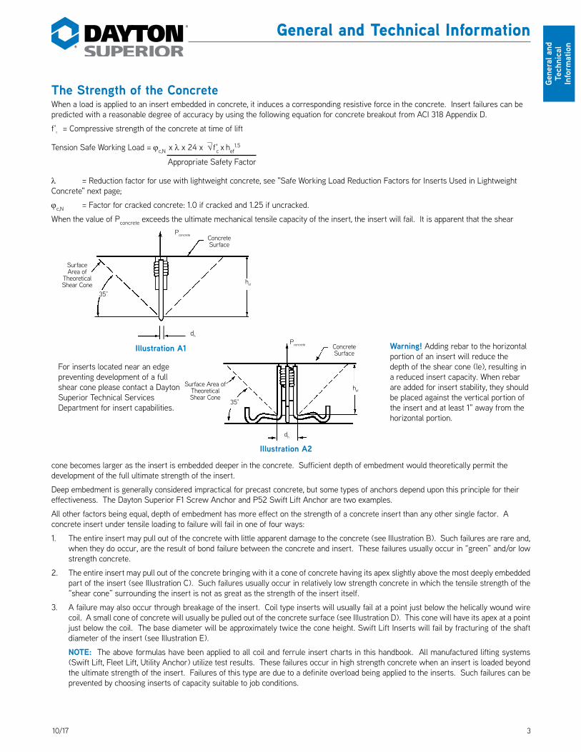
The Strength of the ConcreteWhen a load is applied to an insert embedded in concrete, it induces a corresponding resistive force in the concrete. Insert failures can be predicted with a reasonable degree of accuracy by using the following equation for concrete breakout from ACI 318 Appendix D.
f'c = Compressive strength of the concrete at time of lift
Tension Safe Working Load = jc,N x l x 24 x √ f'c x hef1.5
Appropriate Safety Factor
l = Reduction factor for use with lightweight concrete, see "Safe Working Load Reduction Factors for Inserts Used in Lightweight Concrete" next page;
jc,N = Factor for cracked concrete: 1.0 if cracked and 1.25 if uncracked.
When the value of Pconcrete exceeds the ultimate mechanical tensile capacity of the insert, the insert will fail. It is apparent that the shear
cone becomes larger as the insert is embedded deeper in the concrete. Sufficient depth of embedment would theoretically permit the development of the full ultimate strength of the insert.
Deep embedment is generally considered impractical for precast concrete, but some types of anchors depend upon this principle for their effectiveness. The Dayton Superior F1 Screw Anchor and P52 Swift Lift Anchor are two examples.
All other factors being equal, depth of embedment has more effect on the strength of a concrete insert than any other single factor. A concrete insert under tensile loading to failure will fail in one of four ways:
1. The entire insert may pull out of the concrete with little apparent damage to the concrete (see Illustration B). Such failures are rare and, when they do occur, are the result of bond failure between the concrete and insert. These failures usually occur in “green” and/or low strength concrete.
2. The entire insert may pull out of the concrete bringing with it a cone of concrete having its apex slightly above the most deeply embedded part of the insert (see Illustration C). Such failures usually occur in relatively low strength concrete in which the tensile strength of the “shear cone” surrounding the insert is not as great as the strength of the insert itself.
3. A failure may also occur through breakage of the insert. Coil type inserts will usually fail at a point just below the helically wound wire coil. A small cone of concrete will usually be pulled out of the concrete surface (see Illustration D). This cone will have its apex at a point just below the coil. The base diameter will be approximately twice the cone height. Swift Lift Inserts will fail by fracturing of the shaft diameter of the insert (see Illustration E).
NOTE: The above formulas have been applied to all coil and ferrule insert charts in this handbook. All manufactured lifting systems (Swift Lift, Fleet Lift, Utility Anchor) utilize test results. These failures occur in high strength concrete when an insert is loaded beyond the ultimate strength of the insert. Failures of this type are due to a definite overload being applied to the inserts. Such failures can be prevented by choosing inserts of capacity suitable to job conditions.
Pconcrete Concrete Surface
Surface Area of
Theoretical Shear Cone
35°
Surface Area of Theoretical Shear Cone
Pconcrete Concrete Surface
dh
dh
Illustration A1
Illustration A2
Warning! Adding rebar to the horizontal portion of an insert will reduce the depth of the shear cone (le), resulting in a reduced insert capacity. When rebar are added for insert stability, they should be placed against the vertical portion of the insert and at least 1" away from the horizontal portion.
For inserts located near an edge preventing development of a full shear cone please contact a Dayton Superior Technical Services Department for insert capabilities.
hef
35°
hef

4 10/17
General and Technical
Information
General and Technical Information
4. When bolting coil type inserts, the bolt should always extend the proper amount beyond the bottom of the insert coil. Failure to do this causes the entire bolt load to be transferred to fewer turns of the coil, causing an increased load per weld contact point. The coil will then unwind, much like a corkscrew, resulting in a failure (see Illustration F).
Safe Working Load Reduction Factors for Inserts Used in Lightweight ConcreteInsert safe working loads, shown in this handbook, were derived from analysis and testing of Dayton Superior inserts used in normal weight (150 pcf) concrete. The safe working load of the insert is dependent upon the compressive strength of the concrete in which it is embedded. Therefore, when Dayton Superior inserts are used in lightweight concrete precast elements, the safe working load of the inserts must be recalculated to compensate for the reduction in concrete density. Multiply the published safe working loads by a reduction factor, shown in the table, to obtain the corrected safe working load. The table displays the various reduction factors recommended by Dayton Superior for lightweight concrete.
Concrete Type Safe Working Load Reduction Factor
Normal Weight 1.0
Sand and Lightweight Aggregates 0.85
All Lightweight Materials with a Weight of 110 PCF or more 0.75
All Lightweight Materials with a Weight of 110 PCF or less Verify by Testing
Interested readers are referred to Section 8.6 of the American Concrete Institute’s “Building Code Requirements for Reinforced Concrete” (ACI 318) for additional information.
P
P
PP
P
Illustration DIllustration CIllustration B
Illustration E Illustration F

510/17
Gene
ral a
nd
Tech
nica
l In
form
atio
n
General and Technical Information
Location of InsertEmbedment of inserts closer to an edge than the minimum edge distances, shown in this handbook, will greatly reduce the effective area of the resisting concrete shear cone and will reduce the insert’s tension safe working load. The shaded area of the shear cone, shown in the illustrations below, indicates the extent the shear cone area is reduced. Tension safe working loads of inserts used in thin wall conditions or near a free edge or corner must, therefore, be reduced in proportion to the reduction in effective shear cone area (see Illustrations G & H).
Another condition frequently encountered is that of an insert embedded near a free edge or corner and loaded in a transverse direction to the axis of the bolt, toward the free edge of the concrete. Contact Dayton Superior Technical Assistance for safe working loads of inserts used in this type of condition.
Illustration GIllustration H
D
de
P
D
D
de
P Tension
or P Shear
D = Insert Minimum Edge Distance Required to Develop Insert’s Safe Working Loadde = Actual Edge Distance
Insert PlacementInserts must be placed accurately. An insert’s safe working load decreases sharply if it is not perpendicular to the bearing surface, or if it is not in line with the applied force.
Inserts lend themselves to being located and held correctly (by bolts and brackets or by tying to the reinforcing steel) before the casting operation begins. Failure to achieve proper insert placement is careless field installation. It is also important to place inserts so that the depth of thread is constant for the same size insert throughout a job. This eliminates potential bolt engagement mistakes by the erection crew. Inserts should always be kept clean of dirt, ice or other objects that will interfere with attachment of the lifting hardware.
Wrong(Too Low)
Illustration I
Wrong(Too High)
Wrong(Angled)
Correct
P
1/2" Minimum to Develop Insert Safe
Working Load
90°
Note: For ferrule inserts, establish this dimension and maintain for all similar sized inserts on a project. For coil inserts, the coil bolt must
penetrate through the insert coil by the proper amount.
6 10/17
General and Technical
Information
General and Technical Information
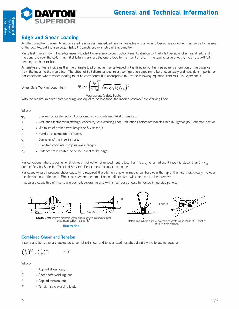
Edge and Shear LoadingAnother condition frequently encountered is an insert embedded near a free edge or corner and loaded in a direction transverse to the axis of the bolt, toward the free edge. Edge lift panels are examples of this condition.
Many tests have shown that edge inserts loaded transversely to destruction (see Illustration L) finally fail because of an initial failure of the concrete over the coil. This initial failure transfers the entire load to the insert struts. If the load is large enough, the struts will fail in bending or shear or both.
An analysis of tests indicates that the ultimate load on edge inserts loaded in the direction of the free edge is a function of the distance from the insert to the free edge. The effect of bolt diameter and insert configuration appears to be of secondary and negligible importance. For conditions where shear loading must be considered, it is appropriate to use the following equation from ACI 318 Appendix D:
Shear Safe Working Load (lbs.) =
With the maximum shear safe working load equal to, or less than, the insert’s tension Safe Working Load.
Where:
jc = Cracked concrete factor: 1.0 for cracked concrete and 1.4 if uncracked.
l = Reduction factor for lightweight concrete, Safe Working Load Reduction Factors for Inserts Used in Lightweight Concrete" section.
le = Minimum of embedment length or 8 x (n x do).
n = Number of struts on the insert.
do = Diameter of the insert struts.
f’c = Specified concrete compressive strength.
ca1 = Distance from centerline of the insert to the edge.
For conditions where a corner or thickness in direction of embedment is less than 1.5 x ca1 or an adjacent insert is closer than 3 x ca1 contact Dayton Superior Technical Services Department for insert capacities.
For cases where increased shear capacity is required, the addition of pre-formed shear bars over the top of the insert will greatly increase the distribution of the load. Shear bars, when used, must be in solid contact with the insert to be effective.
If accurate capacities of inserts are desired, several inserts with shear bars should be tested in job size panels.
Combined Shear and TensionInserts and bolts that are subjected to combined shear and tension loadings should satisfy the following equation:
( fv )5/3 + ( ft )5/3 ≤ 1.0 Fv Ft
Where:
fv = Applied shear load;
Fv = Shear safe working load;
ft = Applied tension load;
Ft = Tension safe working load.
ca1
Shaded areas indicate probable tensile stress pattern in concrete near edge insert subject to load “P.”
Point “X”
Point “X”
P
Dotted line indicates line of probable concrete failure Point “X”– point of possible strut fracture.
Illustration L
ψ ⋅λ⋅7c ⋅n do
1e⋅n do
1.5( )f’c ⋅ c al⋅√ √
0.2
⋅ Appropriate Safety Factor

710/17
Gene
ral a
nd
Tech
nica
l In
form
atio
n
General and Technical Information
Torque-Tension RelationshipFor some types of bolted connections, it may be desirable to have a minimum clamping force (tension load). Due to the many variables associated with tightening bolted connections, it is possible to experience as much as a ± 25% variation in the amount of clamping force applied to similar connections receiving identical torque.
The following equation is taken from “Fasteners Standards – Sixth Edition,” published by Industrial Fasteners Institute, East Ohio Building, 1717 East 9th Street, Suite 1105, Cleveland, Ohio 44114-2879. It is used to provide an “estimate” of the torque required to apply a given preload to a bolted connection.
T = KDP 12
Where: T = Torque (ft. lbs.); K = Torque coefficient; D = Nominal bolt diameter; P = Tension in bolt (Ibs.)
The torque coefficient is the critical factor in the above formula. It is best to experimentally determine K for critical applications using actual connection materials and assembly tools.
Arbitrary values for K are often assigned in non-critical applications, as follows:
K = .20 for NC threaded bolts per “Fasteners Standards – Sixth Edition” K = .30 for Coil threaded bolts per test results.
The torque coefficient will vary from the values, shown above, when bolts have been plated, greased or coated with other types of lubricant.
NC Threaded Bolt CapacitiesPermanent connections in precast construction are normally made with either ferrule inserts or slotted inserts using National Course (NC) threaded bolts. NC threaded bolts are normally not supplied by Dayton Superior. However, as a convenience to the precast designer, the following chart is listed.
NC Threaded Bolt Selection Table
Nominal Bolt Diameter and Threads per Inch
ASTM A-307 Bolts ASTM A-325 or A-449 BoltsTension Shear Tension Shear
1/4"– 20 625 lbs. 350 lbs. 1,250 lbs. 725 lbs.
3/8"– 16 1,500 lbs. 900 lbs. 3,100 lbs. 1,800 lbs.
1/2"– 13 2,800 lbs. 1,700 lbs. 5,600 lbs. 3,400 lbs.
5/8"– 11 4,500 lbs. 2,700 lbs. 9,000 lbs. 5,400 lbs.
3/4"– 10 6,600 lbs. 4,000 lbs. 13,300 lbs. 8,100 lbs.
7/8"– 9 9,200 lbs. 5,600 lbs. 18,400 lbs. 11,300 lbs.
1"– 8 12,100 lbs. 7,400 lbs. 24,200 lbs. 14,900 lbs.
1-1/8"– 7 15,200 lbs. 9,400 lbs. 26,700 lbs. 16,400 lbs.
1-1/4"– 7 19,300 lbs. 12,000 lbs. 33,900 lbs. 21,000 lbs.
1-1/2"– 6 28,100 lbs. 17,500 lbs. 49,100 lbs. 30,600 lbs.
Safe working loads shown provide a factor of safety of approximately 3 to 1 (ultimate to Safe Working Load). Shear Safe Working Load assumes that the threads are included in the shear plane. 1/4"–20, 3/8"–16 and 1/2"–13 bolts are not recommended for use as structural fasteners. For combined shear/tension interaction, refer to page 12.
Condition of LoadingsAll safe working loads shown in this handbook are for static load conditions only. If dynamic forces or impact loading conditions are anticipated, the safe working load must be reduced accordingly.
Care must be exercised to see that all inserts and hardware units are properly aligned, all lifting plates and bolts properly secured, all rigging is equalized, and properly sized crane cables utilized.
Warning: When in doubt about the proper use or installation of a Dayton Superior precast product, contact Dayton Superior for clarification. Failure to do so may result in safety hazards, exposing workers in the vicinity of the precast yard or job site to the possibility of injury or death.

8 10/17
General and Technical
Information
General and Technical Information
Corrosion ProtectionThe Dayton Superior precast products shown in this handbook are available in several different finishes or coatings. These finishes vary in the degree of corrosion protection provided. Standard finish is PLAIN and will normally be furnished if no finish is specified. Finishes available are as follows:
PLAIN or unfinished steel is sometimes referred to as BLACK or RAW. PLAIN finished material will rust when exposed to the environment.
ELECTRO-GALVANIZED finish is a zinc plated finish that provides a varying degree of corrosion protection depending on the thickness of the zinc plating and type of after-plating coating specified. This finish is recommended for threaded products. DaytonSuperior electro-galvanizing conforms to ASTM Standard B-633, Service Condition 1 as plated. Other options available underthis ASTM Standard are listed below.
HOT DIPPED GALVANIZED or HDG products are zinc coated by the hot-dipped process and will provide better corrosion protection than electro-galvanized finished products due to the thicker HDG zinc coating. This finish is not recommended for threaded products due to potential assembly problems. Dayton Superior hot dipped galvanizing conforms to ASTM A-123 or A-153.
EPOXY-POLYESTER or EPOXY finish is a dielectric material that is used to provide corrosion protection for steel products that are to be embedded in precast concrete. This material is usually applied to a coating thickness between 5 and 12 mils. Epoxy-Polyester finish is normally specified when an affordable solution to salt spray corrosion is required. Not recommended for use where threads are to be coated. STAINLESS STEEL is recommended for its excellent corrosion protection that will resist ordinary rusting. Type 304 Stainless Steel is recommended for use in precast products. It is the most economical type of stainless steel available for its level of corrosion resistance. Note that Type 304 Stainless Steel will rust when exposed to certain chemicals used to acid wash the surface of architectural precast concrete.
ASTM Standards For Corrosion Resisting CoatingsASTM A-123 Zinc (Hot Dipped Galvanized) Coating on Iron or Steel
Product Type Material Approximate Thickness
Wire .142" to .186" diameter .002"
Wire .187" to .249" diameter .003"
Wire .250" diameter or larger .004"
Steel or Plate .030" to .062" thick .002"
Steel or Plate .063" to .124" thick .003"
Steel or Plate .125" or thicker .004"
ASTM A-153 Zinc Coatings (Hot Dip) on Iron or Steel HardwareProduct Type Class Approximate Thickness
Castings A .004"
Steel, 3/16" and thicker B1 .004"
Steel, 3/16" and thinner B2 .003"
ASTM B-633 Electro Deposited Coatings of Zinc on Iron and SteelService Condition Exposure Approximate Thickness
SC-4 .001" Very Severe
SC-3 .0005" Severe
SC-2 .0003" Moderate
SC-1 .0002" Mild
ASTM B-633 ContinuedType After Plating Coating Note: Electro-galvanized or hot dipped galvanized items
fabricated from medium high carbon or high carbon steel must be properly treated to minimize hydrogen embrittlement. Failure to properly bake these items may result in a drastic reduction in their safe working load and premature failure resulting in property damage, injuries or death.
1 As Plated
2 Colored Chromate
3 Colorless Chromate
4 Phosphate

910/17
Gene
ral a
nd
Tech
nica
l In
form
atio
n
General and Technical Information
Condition of LoadingThe preceding paragraphs have been devoted to the behavior of concrete inserts under straight tensile loading. Obviously, there are many conditions of loading other than direct tension. Most situations will require consideration of shearing and/or bending forces applied to the insert through the anchor bolt or other connecting hardware. A common condition occurs when a precast concrete element is lifted by means of inserts in each end without a spreader bar (see Illustration J). When a load P is carried by only two inserts, the vertical reaction R that must be carried by each insert is 1/2 P. There is also an additional vertical force V, that must be added to R, that is caused by the horizontal component H of force T.
The horizontal force H that is exerted on the insert and on the concrete surrounding it is proportional to the total load and to the angle a included between the sling and the surface of the concrete. This force may be expressed by the equation:
H = P (cot a). 2
The magnitude of the tensile force on the sling is proportional to the total load and to the angle a. This force may be expressed by the equation:
T = P 2 sin a .
As angle a decreases, the values of H and T increase. As angle a approaches 0°, the magnitude of both H and T approaches infinity. Conversely, as angle a increases, the values of H and T decrease, so that as angle a approaches 90°, force T approaches the value of 1/2 P and force H approaches 0.
It is readily apparent that the use of long slings will greatly reduce destructive forces on the slings, the lifting hardware and on the precast element itself.
H = Horizontal component of sling load which is equal to the induced shear load.
V = Vertical force on insert caused by force H applied at distance e from face of concrete.C = Resultant of compressive forces on concrete.d = Distance from center line of anchor bolt to toe of bearing plate.e = Distance from face of concrete to point of application of force H.x = Distance from toe of bearing plate to C.b = Width of bearing plate–(not shown)f’c = Ultimate compression strength of the concrete.
aSee Detail A
Illustration J
P
Detail A
T
H
R = 1/2 P
Illustration K
d
He
SHEAR
C
X
V
(d - x)
10 10/17
General and Technical
Information
General and Technical Information
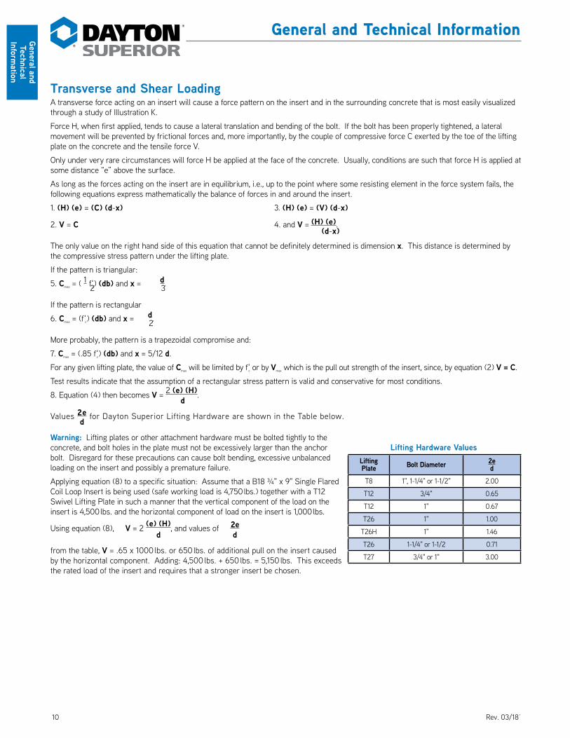
Transverse and Shear LoadingA transverse force acting on an insert will cause a force pattern on the insert and in the surrounding concrete that is most easily visualized through a study of Illustration K.
Force H, when first applied, tends to cause a lateral translation and bending of the bolt. If the bolt has been properly tightened, a lateral movement will be prevented by frictional forces and, more importantly, by the couple of compressive force C exerted by the toe of the lifting plate on the concrete and the tensile force V.
Only under very rare circumstances will force H be applied at the face of the concrete. Usually, conditions are such that force H is applied at some distance “e” above the surface.
As long as the forces acting on the insert are in equilibrium, i.e., up to the point where some resisting element in the force system fails, the following equations express mathematically the balance of forces in and around the insert.
1. (H) (e) = (C) (d-x) 3. (H) (e) = (V) (d-x)
2. V = C 4. and V = (H) (e). (d-x)
The only value on the right hand side of this equation that cannot be definitely determined is dimension x. This distance is determined by the compressive stress pattern under the lifting plate.
If the pattern is triangular:
5. Cmax = ( 1 f'c) (db) and x = d. 2 3
If the pattern is rectangular
6. Cmax = (f'c) (db) and x = d. 2
More probably, the pattern is a trapezoidal compromise and:
7. Cmax = (.85 f'c) (db) and x = 5/12 d.
For any given lifting plate, the value of Cmax will be limited by f'c or by Vmax which is the pull out strength of the insert, since, by equation (2) V = C.
Test results indicate that the assumption of a rectangular stress pattern is valid and conservative for most conditions.
8. Equation (4) then becomes V = 2 (e) (H). d
Values 2e for Dayton Superior Lifting Hardware are shown in the Table below. d
Warning: Lifting plates or other attachment hardware must be bolted tightly to the concrete, and bolt holes in the plate must not be excessively larger than the anchor bolt. Disregard for these precautions can cause bolt bending, excessive unbalanced loading on the insert and possibly a premature failure.
Applying equation (8) to a specific situation: Assume that a B18 ¾" x 9" Single Flared Coil Loop Insert is being used (safe working load is 4,750 lbs.) together with a T12 Swivel Lifting Plate in such a manner that the vertical component of the load on the insert is 4,500 lbs. and the horizontal component of load on the insert is 1,000 lbs.
Using equation (8), V = 2 (e) (H), and values of 2e d d
from the table, V = .65 x 1000 lbs. or 650 lbs. of additional pull on the insert caused by the horizontal component. Adding: 4,500 lbs. + 650 lbs. = 5,150 lbs. This exceeds the rated load of the insert and requires that a stronger insert be chosen.
Lifting Hardware ValuesLifting Plate Bolt Diameter 2e
dT8 1", 1-1/4" or 1-1/2" 2.00
T12 3/4" 0.65
T12 1" 0.67
T26 1" 1.00
T26H 1" 1.46
T26 1-1/4" or 1-1/2 0.71
T27 3/4" or 1" 3.00
Rev. 03/18
1110/17
Gene
ral a
nd
Tech
nica
l In
form
atio
n
General and Technical Information
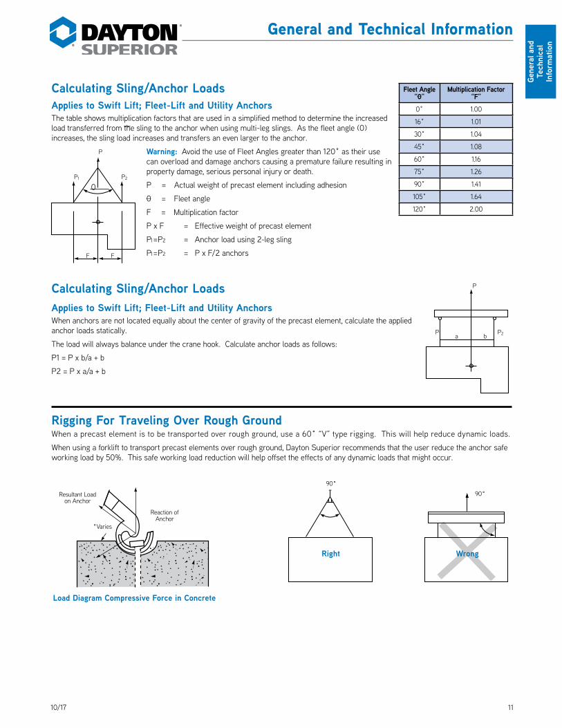
Calculating Sling/Anchor LoadsApplies to Swift Lift; Fleet-Lift and Utility AnchorsThe table shows multiplication factors that are used in a simplified method to determine the increased load transferred from the sling to the anchor when using multi-leg slings. As the fleet angle (0) increases, the sling load increases and transfers an even larger to the anchor.
Warning: Avoid the use of Fleet Angles greater than 120˚ as their use can overload and damage anchors causing a premature failure resulting in property damage, serious personal injury or death.
P = Actual weight of precast element including adhesion
0 = Fleet angle
F = Multiplication factor
P x F = Effective weight of precast element
P1 = P2 = Anchor load using 2-leg sling
P1 = P2 = P x F/2 anchors
Calculating Sling/Anchor LoadsApplies to Swift Lift; Fleet-Lift and Utility AnchorsWhen anchors are not located equally about the center of gravity of the precast element, calculate the applied anchor loads statically.
The load will always balance under the crane hook. Calculate anchor loads as follows:
P1 = P x b/a + b
P2 = P x a/a + b
Rigging For Traveling Over Rough GroundWhen a precast element is to be transported over rough ground, use a 60˚ “V” type rigging. This will help reduce dynamic loads.
When using a forklift to transport precast elements over rough ground, Dayton Superior recommends that the user reduce the anchor safe working load by 50%. This safe working load reduction will help offset the effects of any dynamic loads that might occur.
P
F F
P1 P2
0
Right Wrong
90˚
Load Diagram Compressive Force in Concrete
Reaction of Anchor
Resultant Load on Anchor
˚Varies
90˚
P2P1 a b
P
Fleet Angle “0”
Multiplication Factor “F”
0˚ 1.00
16˚ 1.01
30˚ 1.04
45˚ 1.08
60˚ 1.16
75˚ 1.26
90˚ 1.41
105˚ 1.64
120˚ 2.00
12 10/17
General and Technical
Information
General and Technical Information
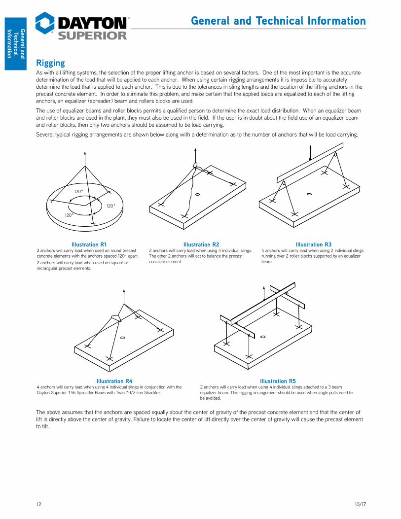
RiggingAs with all lifting systems, the selection of the proper lifting anchor is based on several factors. One of the most important is the accurate determination of the load that will be applied to each anchor. When using certain rigging arrangements it is impossible to accurately determine the load that is applied to each anchor. This is due to the tolerances in sling lengths and the location of the lifting anchors in the precast concrete element. In order to eliminate this problem, and make certain that the applied loads are equalized to each of the lifting anchors, an equalizer (spreader) beam and rollers blocks are used.
The use of equalizer beams and roller blocks permits a qualified person to determine the exact load distribution. When an equalizer beam and roller blocks are used in the plant, they must also be used in the field. If the user is in doubt about the field use of an equalizer beam and roller blocks, then only two anchors should be assumed to be load carrying.
Several typical rigging arrangements are shown below along with a determination as to the number of anchors that will be load carrying.
120˚
120˚
120˚
Illustration R13 anchors will carry load when used on round precast concrete elements with the anchors spaced 120˚ apart.2 anchors will carry load when used on square or rectangular precast elements.
Illustration R22 anchors will carry load when using 4 individual slings. The other 2 anchors will act to balance the precast concrete element.
Illustration R34 anchors will carry load when using 2 individual slings running over 2 roller blocks supported by an equalizer beam.
Illustration R44 anchors will carry load when using 4 individual slings in conjunction with the Dayton Superior T46 Spreader Beam with Twin 7-1/2-ton Shackles.
Illustration R52 anchors will carry load when using 4 individual slings attached to a 3 beam equalizer beam. This rigging arrangement should be used when angle pulls need to be avoided.
The above assumes that the anchors are spaced equally about the center of gravity of the precast concrete element and that the center of lift is directly above the center of gravity. Failure to locate the center of lift directly over the center of gravity will cause the precast element to tilt.

1310/17
Gene
ral a
nd
Tech
nica
l In
form
atio
n
General and Technical Information
Selecting the Proper InsertThe following factors should be considered when determining the load per insert:
1) Weight of the concrete shape, 2) Adhesion to the form surface, 3) Type of concrete (normal, lightweight or all lightweight materials), 4) Dynamic loads (impact due to handling, transporting or erecting conditions), 5) Concrete compressive strength at time of initial lift, 6) Number of lifting points and type of rigging to be used, 7) Direction of pull (cable or sling angle), 8) Flexural stresses of thin concrete shapes, 9) Panel thickness, 10) Edge distance (thin wall, free edge or shear loading conditions).Determining the dead load weight of a precast concrete section is straight forward, although serious errors are easy to make, such as: 1. Miscalculations involving symmetrical panels; 2. Forgetting that a panel is normal weight concrete and using the unit weights of lightweight concrete and 3. Neglecting adhesion to the form.
In addition, transporting the panel in the storage yard over bumpy conditions introduces dynamic loads that must also be anticipated. Removing the precast element from the form can induce forces that, in effect, increase the dead load weight at a critical time, when the concrete compressive strength is at its lowest value. Depending on the quality of release agent used, the following adhesion loads should be considered when determining the “additional” weight of the concrete element:
Concrete Forms up to 20 Ibs./sq. ft.
Steel Forms up to 25 Ibs./sq. ft.
Plywood Forms up to 50 Ibs./sq. ft. (Flat Surface)
Plywood Forms up to 75 Ibs./sq. ft. (Ribbed Surface)
The type of concrete used determines the unit weight characteristics and the resultant ability of the concrete to resist the pullout forces introduced by the insert. See page 8 for the proper load reduction factors that must be applied to insert safe working loads when an insert is embedded in lightweight concrete.
Consideration must also be given to dynamic loads that can occur in the plant, in the storage yard, as well as during transportation to the job site and during erection. It is suggested that a detailed study be made of the various handling, storage, transporting and erection forces. The user is cautioned to be aware of these additional forces and to give due consideration to their effect on the insert’s safe working load.
Example OneSelect the proper length and capacity of insert based on the use of a spreader frame, as shown below, that will allow equal loading on all four inserts. Assume normal weight concrete having a compressive strength of 2,700 psi at initial lift.
Dead Load Weight = 15' x 8' x 12.5 Ibs./sq. ft. x 6" = 9,000 Ibs.
Adhesion to Form = 15' x 8' x 75 Ibs./sq. ft. = 9,000 Ibs. (Ribbed Surface)
Effective Weight of Panel = 18,000 Ibs.
Required Insert Capacity = 18,000 Ibs. = 4,500 Ibs./insert 4 inserts
Maximum Insert Height = 5-1/2"
Select the following insert: P52 4 ton x 4¾" long Swift Lift Anchor in 3,000 psi normal weight concrete.
Illustration M
90°6"
15'-0
"
8'-0"

14 10/17
General and Technical
Information
General and Technical Information
Illustration P
14" 60°10
'-0"
9'-0"
Illustration N
20'-0
"6"60°
7'-0"
Example TwoSelect the proper length and capacity of insert, based on the use of a spreader beam and slings at a 60° angle with the top surface of the precast section. Assume normal weight concrete having a compressive strength of 4,000 psi at initial lift and the use of 1" diameter T12 Swivel Lifting Plates.
Dead Load Weight = 20' x 7' x 12.5 Ibs./sq. ft. x 6" = 10,500 Ibs.Adhesion to Form = 20' x 7' x 25 Ibs./sq. ft. = 3,500 Ibs.Effective Weight of Panel = 14,000 Ibs.-
Therefore, the vertical reaction that must be carried by each
insert = 14,000 lbs. = 3,500 lbs. 4 insertsH = 3,500 Ibs. x cot. 60° = 3,500 Ibs. x .578 orH = 2,023 Ibs./insert
V = 2 e x 2,023 Ibs. = .65 x 2,023 or d
V = 1,315 Ibs./insertRequired Insert Capacity = 3,500 Ibs. + 1,315 Ibs. = 4,815 Ibs./insertMaximum Insert Height = 5½"Select the following insert: F56 Expanded Coil Insert, 1" diameter x 5-1/2" long, 6,250 Ibs. Safe Working Load.Check combined tension and shear as follows:
( 4,815 lbs. )5/3 + ( 2,023 lbs. )5/3 = .80. Since this is less than 1.0, the insert which was
6,250 lbs. 4,800 lbs. selected is suitable for use.
Example ThreeSelect the proper length and capacity of an insert based on the use of a four sling lift (see warning note below) with cables at a 60° angle to the top surface of the precast section. Assume lightweight concrete having a unit weight of 115 lbs./cu. ft., a compressive strength at initial lift of 4,000 psi and the use of 1-1/2" diameter T12 Swivel Lift Plates.
Dead Load Weight = 9' x 10' x 9.58 Ibs./sq. ft. x 14" = 12,071 Ibs.Adhesion to Form = 9' x 10' x 20 Ibs./sq. ft. = 1,800 Ibs.Effective Weight of Precast Section = 13,871 Ibs.Therefore, the vertical reaction that must be carried by each
insert = 13,871 lbs. = 6,936 lbs. 2 inserts
H = 6,936 Ibs. x cot. 60° = 6,936 Ibs. x .578 orH = 4,009 Ibs./insert
V = 2 e x 4,009 Ibs. = .833 x 4,009 Ibs. or d V = 3,339 Ibs./insertRequired Insert Capacity = 6,936 Ibs. + 3,339 Ibs. = 10,275 Ibs./insertMaximum Insert Height = 13-1/2"Select the F60 Expanded Coil Insert, 1-1/2" diameter x 12" long, 16,250 lbs. Safe Working Load.Multiply Safe Working Load by reduction factor of .7 for lightweight concrete,16,250 Ibs. x .7 = 11,375 Ibs. Safe Working Load in lightweight concrete.
As the reduced Safe Working Load is greater than the 10,275 Ibs. Ioad required, it appears this insert is suitable for use. However, combined shear and tension must be checked as follows:
(10,275 lbs.)5/3 + ( 4,009 lbs. )5/3 = 1.01, which means this insert must be replaced with a stronger insert.
11,375 lbs.
11,750 lbs.
Warning: When individual slings are used, any two inserts must be capable of lifting/handling the precast section. This is due to unequal sling lengths and the resulting loads that are transferred to the shorter slings. In this application, only two slings carry the total load while the other two slings are simply used to balance the load.
1510/17
Gene
ral a
nd
Tech
nica
l In
form
atio
n
General and Technical Information
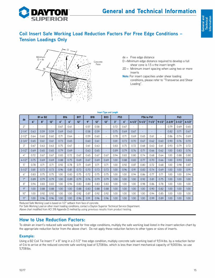
Coil Insert Safe Working Load Reduction Factors For Free Edge Conditions – Tension Loadings Only
Insert Type and Length
deB1 or B2 B16 B17 B18 B33 F53 F56 to F61 F63
6" 8" 12" 4" 6" 12" 9" 12" 12" 3" 4" 4-1/2" 5-1/2" 7-1/2" 9-1/2" 2-2/8" 3-1/2" 4-1/2"2" - - - 0.67 0.61 - 0.57 0.58 - 0.72 0.67 - - - - 0.79 0.69 0.65
2-1/4" 0.63 0.59 0.59 0.69 0.63 - 0.58 0.59 - 0.75 0.69 0.67 - - - 0.82 0.71 0.67
2-1/2" 0.64 0.60 0.60 0.71 0.64 - 0.59 0.60 - 0.78 0.71 0.69 0.65 0.61 - 0.86 0.74 0.69
2-3/4" 0.65 0.61 0.61 0.73 0.65 - 0.60 0.61 - 0.81 0.73 0.70 0.67 0.62 0.60 0.90 0.76 0.70
3" 0.67 0.63 0.63 0.75 0.67 - 0.61 0.63 - 0.83 0.75 0.72 0.68 0.63 0.61 0.93 0.79 0.72
3-1/2" 0.69 0.65 0.65 0.79 0.69 - 0.63 0.65 - 0.89 0.79 0.76 0.71 0.66 0.62 1.00 0.83 0.76
4" 0.72 0.67 0.67 0.83 0.72 0.67 0.65 0.67 0.67 0.94 0.83 0.80 0.74 0.68 0.64 1.00 0.88 0.80
4-1/2" 0.75 0.69 0.69 0.88 0.75 0.69 0.67 0.69 0.69 1.00 0.88 0.83 0.77 0.70 0.66 1.00 0.93 0.83
5" 0.78 0.71 0.71 0.92 0.78 0.71 0.69 0.71 0.71 1.00 0.92 0.87 0.80 0.72 0.68 1.00 0.98 0.87
5-1/2" 0.81 0.73 0.73 0.96 0.81 0.73 0.70 0.73 0.73 1.00 0.96 0.91 0.83 0.74 0.69 1.00 1.00 0.91
6" 0.83 0.75 0.75 1.00 0.83 0.75 0.72 0.75 0.75 1.00 1.00 0.94 0.86 0.77 0.71 1.00 1.00 0.94
7" 0.89 0.79 0.79 1.00 0.89 0.79 0.76 0.79 0.79 1.00 1.00 1.00 0.92 0.81 0.75 1.00 1.00 1.00
8" 0.94 0.83 0.83 1.00 0.94 0.83 0.80 0.83 0.83 1.00 1.00 1.00 0.98 0.86 0.78 1.00 1.00 1.00
9" 1.00 0.88 0.88 1.00 1.00 0.88 0.83 0.88 0.88 1.00 1.00 1.00 1.00 0.90 0.82 1.00 1.00 1.00
10" 1.00 0.92 0.92 1.00 1.00 0.92 0.87 0.92 0.92 1.00 1.00 1.00 1.00 0.94 0.85 1.00 1.00 1.00
11" 1.00 0.96 0.96 1.00 1.00 0.96 0.91 0.96 0.96 1.00 1.00 1.00 1.00 0.99 0.89 1.00 1.00 1.00
Reduced Safe Working Load is based on 1/2" setback from face of concrete.For Safe Working Load on other insert loading conditions, contact a Dayton Superior Technical Service Department.Above chart modified from ACI 318 Appendix D method by using previous results from product testing.
How to Use Reduction Factors:To obtain an insert’s reduced safe working load for free edge conditions, multiply the safe working load listed in the insert selection chart by the appropriate reduction factor from the above chart. Do not apply these reduction factors to other types or sizes of inserts.
Example:Using a B2 Coil Tie Insert 1" x 8" long in a 2-1/2" free edge condition, multiply concrete safe working load of 9,514 lbs. by a reduction factor of 0.6 to arrive at the reduced concrete safe working load of 5,708 lbs. which is less than insert mechanical capacity of 9,000 lbs. so use 5,708 lbs.
Minimum D + de
de
P
D
Concrete Face
de = Free edge distanceD = Minimum edge distance required to develop a full
shear cone is 1.5 x the insert length2D = Minimum insert spacing when using two or more
insertsNote: For insert capacities under shear loading
conditions, please refer to “Transverse and Shear Loading”.
16 10/17
General and Technical
Information
General and Technical Information
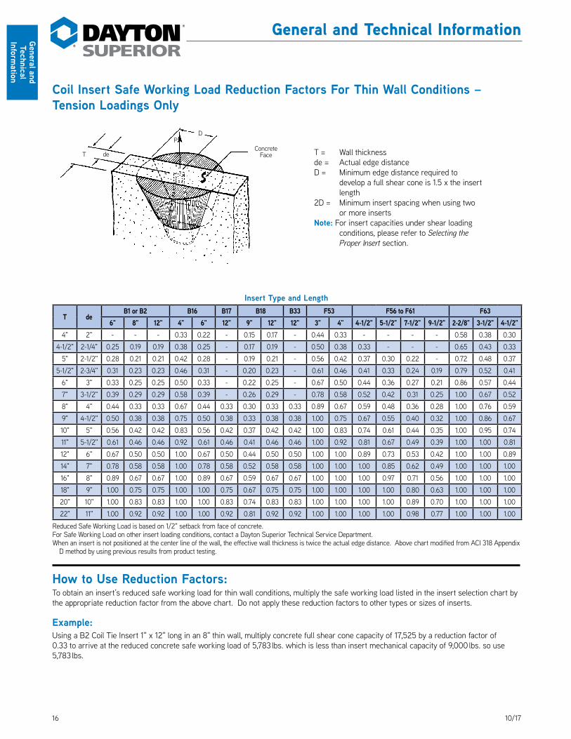
Coil Insert Safe Working Load Reduction Factors For Thin Wall Conditions – Tension Loadings Only
Insert Type and Length
T deB1 or B2 B16 B17 B18 B33 F53 F56 to F61 F63
6" 8" 12" 4" 6" 12" 9" 12" 12" 3" 4" 4-1/2" 5-1/2" 7-1/2" 9-1/2" 2-2/8" 3-1/2" 4-1/2"4" 2" - - - 0.33 0.22 - 0.15 0.17 - 0.44 0.33 - - - - 0.58 0.38 0.30
4-1/2" 2-1/4" 0.25 0.19 0.19 0.38 0.25 - 0.17 0.19 - 0.50 0.38 0.33 - - - 0.65 0.43 0.33
5" 2-1/2" 0.28 0.21 0.21 0.42 0.28 - 0.19 0.21 - 0.56 0.42 0.37 0.30 0.22 - 0.72 0.48 0.37
5-1/2" 2-3/4" 0.31 0.23 0.23 0.46 0.31 - 0.20 0.23 - 0.61 0.46 0.41 0.33 0.24 0.19 0.79 0.52 0.41
6" 3" 0.33 0.25 0.25 0.50 0.33 - 0.22 0.25 - 0.67 0.50 0.44 0.36 0.27 0.21 0.86 0.57 0.44
7" 3-1/2" 0.39 0.29 0.29 0.58 0.39 - 0.26 0.29 - 0.78 0.58 0.52 0.42 0.31 0.25 1.00 0.67 0.52
8" 4" 0.44 0.33 0.33 0.67 0.44 0.33 0.30 0.33 0.33 0.89 0.67 0.59 0.48 0.36 0.28 1.00 0.76 0.59
9" 4-1/2" 0.50 0.38 0.38 0.75 0.50 0.38 0.33 0.38 0.38 1.00 0.75 0.67 0.55 0.40 0.32 1.00 0.86 0.67
10" 5" 0.56 0.42 0.42 0.83 0.56 0.42 0.37 0.42 0.42 1.00 0.83 0.74 0.61 0.44 0.35 1.00 0.95 0.74
11" 5-1/2" 0.61 0.46 0.46 0.92 0.61 0.46 0.41 0.46 0.46 1.00 0.92 0.81 0.67 0.49 0.39 1.00 1.00 0.81
12" 6" 0.67 0.50 0.50 1.00 0.67 0.50 0.44 0.50 0.50 1.00 1.00 0.89 0.73 0.53 0.42 1.00 1.00 0.89
14" 7" 0.78 0.58 0.58 1.00 0.78 0.58 0.52 0.58 0.58 1.00 1.00 1.00 0.85 0.62 0.49 1.00 1.00 1.00
16" 8" 0.89 0.67 0.67 1.00 0.89 0.67 0.59 0.67 0.67 1.00 1.00 1.00 0.97 0.71 0.56 1.00 1.00 1.00
18" 9" 1.00 0.75 0.75 1.00 1.00 0.75 0.67 0.75 0.75 1.00 1.00 1.00 1.00 0.80 0.63 1.00 1.00 1.00
20" 10" 1.00 0.83 0.83 1.00 1.00 0.83 0.74 0.83 0.83 1.00 1.00 1.00 1.00 0.89 0.70 1.00 1.00 1.00
22" 11" 1.00 0.92 0.92 1.00 1.00 0.92 0.81 0.92 0.92 1.00 1.00 1.00 1.00 0.98 0.77 1.00 1.00 1.00
Reduced Safe Working Load is based on 1/2" setback from face of concrete.For Safe Working Load on other insert loading conditions, contact a Dayton Superior Technical Service Department.When an insert is not positioned at the center line of the wall, the effective wall thickness is twice the actual edge distance. Above chart modified from ACI 318 Appendix
D method by using previous results from product testing.
How to Use Reduction Factors:To obtain an insert’s reduced safe working load for thin wall conditions, multiply the safe working load listed in the insert selection chart by the appropriate reduction factor from the above chart. Do not apply these reduction factors to other types or sizes of inserts.
Example:Using a B2 Coil Tie Insert 1" x 12" long in an 8" thin wall, multiply concrete full shear cone capacity of 17,525 by a reduction factor of 0.33 to arrive at the reduced concrete safe working load of 5,783 lbs. which is less than insert mechanical capacity of 9,000 lbs. so use 5,783 lbs.
T de
PD
Concrete Face T = Wall thickness
de = Actual edge distanceD = Minimum edge distance required to
develop a full shear cone is 1.5 x the insert length
2D = Minimum insert spacing when using two or more inserts
Note: For insert capacities under shear loading conditions, please refer to Selecting the Proper Insert section.
1710/17
Swift Lift® System
Swift
Lift
Sys
tem
Swift Lift® SystemThe Swift Lift System is a quick connect-disconnect system that allows precast concrete elements to be handled repeatedly, with speed, safety and economy. It is a non-welded system and void of threaded connections. The quality, reusable Swift Lift Lifting Eye’s heavy duty construction will provide years of good service.
The Swift Lift System is available with safe load ratings of 1, 2, 4, 8 and 20 tons. Each component is clearly marked with its maximum safe working load. The System is extremely versatile and can be utilized for vertical and diagonal pulls. It can be used to lift concrete elements from a horizontal to a vertical position without the aid of a tilting table.
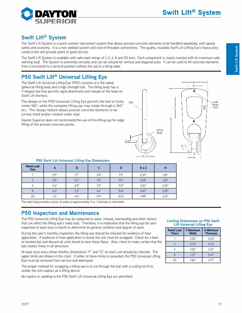
P50 Swift Lift® Universal Lifting EyeThe Swift Lift Universal Lifting Eye (P50) consists of a flat-sided, spherical lifting body and a high strength bail. The lifting body has a T-shaped slot that permits rapid attachment and release of the head on Swift Lift Anchors. DS_P50
The design of the P50 Universal Lifting Eye permits the bail to freely rotate 180°, while the complete lifting eye may rotate through a 360° arc. This design feature allows precast concrete elements to be turned, tilted and/or rotated under load.
Dayton Superior does not recommend the use of this lifting eye for edge lifting of thin precast concrete panels.
P50 Swift Lift Universal Lifting Eye DimensionsRated Load
Tons A B C D E x 2 H
1 2.9" 1.7" 2.8" 7.5" 2.20" 1.26"
2 3.5" 2.3" 3.3" 9.0" 2.68" 1.65"
4 4.6" 2.8" 3.5" 11.0" 3.46" 2.26"
8 6.3" 3.3" 4.4" 15.6" 4.40" 2.90"
20 7.3" 4.6" 5.9" 20.4" 5.98" 4.35"
The rated load provides a factor of safety of approximately 5 to 1 (ultimate to rated load).
P50 Inspection and MaintenanceThe P50 Universal Lifting Eye may be subjected to wear, misuse, overloading and other factors that can affect the lifting eye’s rated load. Therefore, it is imperative that the lifting eye be user-inspected at least once a month to determine its general condition and degree of wear.
During the user’s monthly inspection, the lifting eye should be checked for evidence of heat application. If evidence of heat application is found, the unit must be scrapped. Check for a bent or twisted bail and discard all units found to have these flaws. Also, check to make certain that the bail rotates freely in all directions.
At least once every three months, dimensions “F” and “G” on each unit should be checked. The upper limits are shown in the chart. If either of these limits is exceeded, the P50 Universal Lifting Eye must be removed from service and destroyed.
The proper method for scrapping a lifting eye is to cut through the bail with a cutting torch to render the unit useless as a lifting device.
No repairs or welding to the P50 Swift Lift Universal Lifting Eye are permitted.
Load Range Tons
Bail
E x 2FH
BA
G
D
C
Lifting Body
DSC
4
4
Limiting Dimensions on P50 Swift Lift Universal Lifting Eye
Rated Load (Tons)
F Maximum Width
G Minimum Thickness
1 0.56" 0.22"
2 0.76" 0.23"
4 1.02" 0.31"
8 1.31" 0.47"
20 1.86" 0.71"

18 10/17
Swift Lift® System
Swift Lift System
How to Use the P50 Swift Lift Universal Lifting Eye
Dos and Don’ts of the P50 Swift Lift Universal Lifting Eye
1. To install the P50 lifting eye, hold the unit upside down with the T-shaped slot directly over the head of the Swift Lift anchor.
2. Lower the lifting eye down onto the anchor until the T slot engages the head of the anchor.
3. Rotate the lifting eye until the extended lip of the body touches the horizontal surface of the concrete.
Extended Lip
The bail of the P50 lifting eye can move through a 180° usable range.
The main body of the lifting eye has a 360° rotational range.
The P50 lifting can be safely used with the T-shaped slot facing away from or toward the direction of the applied load.
180° Usable Range
Minimum Edge
Distance
Minimum Edge
Distance
360°Range
To disengage the lifting eye, the crane hook is lowered and the body removed by rotating the extended lip upward.
Note: Prior to lifting a precast element, apply an initial cable tension to make sure that the bail and body of the lifting eye are aligned in the direction of the cable pull.
Prior to lifting a precast element, apply an initial cable tension to make certain that the bail and body of the lifting eye are aligned in the direction of the cable pull.
When applying the initial cable tension on
edge lift applications, make sure that the cables are at a 90° angle (or larger) to the surface of the precast element.Warning: Do not allow the crane lines to form an angle less than 90° during an edge lift application. This
condition can bend the lifting eye bail and could lead to a premature failure.
Warning: The crane line and bail of the lifting hardware must be turned in the direction of the cable forces before the lifting operation begins. The crane line must not be allowed to apply a sideward force on the bail. This condition is dangerous and could lead to premature failure of the hardware or insert.Warning: Do not modify, weld or alter in any way the Swift Lift Universal Lifting Eye.
Right
90° or more
Wrong
Less than 90°
Right

1910/17
Swift Lift® System
Swift
Lift
Sys
tem
P51 Swift Lift® Lifting EyeThe P51 Swift Lift Lifting eye is a high quality, high strength steel casting. Its ball-shaped lower end fits into the void formed in the concrete and engages the spherical head of the anchor. Attachment to the anchor head can only be made when the lifting eye is positioned with its front face toward the concrete. In the working position, release is impossible. Accidental disengagement is prevented by a gravity-action safety pin that must be raised before the Lifting Eye can be removed. DS_P51
The P51 Swift Lift Lifting Eye is available with safe working loads of 2, 4 and 8 tons. It is extremely versatile in use, being suitable for vertical pull or diagonal pull. The Lifting Eye rotates freely (360°) about the vertical axis of the anchor. Each unit is clearly marked with its MAXIMUM safe working load.
Inspection and MaintenanceWhile appreciable wear does not normally occur, the P51 Swift Lift Lifting Eye may be subjected to wear, misuse, overloading and other factors that may affect the lifting eye’s rated load. Therefore, the user must inspect lifting eyes at least once a month to determine general condition, degree of wear and any evidence of heat application.
If evidence of heat application is found, the unit must be destroyed. In addition, check to make certain that the bail is not bent or twisted. Destroy all units that have a bent or twisted bail.
Check the safety pin; missing pins must be replaced. Make sure the safety pin is in good condition and moves freely at all times. At least once every three months, dimension “G” on each unit should be checked. The upper limits are shown in the chart. If either of these limits is exceeded, the Swift Lift Lifting Eye must be removed from service and destroyed.
The proper method to use in destroying a lifting eye is to cut through the bail with a cutting torch. Other than replacing the safety pin, no repairs to the P51 Swift Lift Lifting Eye are permitted. In particular, welding is not permitted.
Year of Manufacture
Safety Pin
H
F
J
L
DSC
4
4
Load RangeTons
Bail
BA
D
P51 Swift Lift Lifting Eye DimensionsRated Load
Tons A B D J L
2 2.63 4.53 2.36 3.74 8.43
4 3.02 5.13 2.83 4.96 10.35
8 3.53 5.98 3.70 5.60 12.87
Safe Working Load provides a factor of safety of approximately 5 to 1.
Limiting Dimensions on P51 Swift Lift Lifting Eye
Rated Load (Tons)
H (Maximum)
2 0.759"
4 1.034"
8 1.310"

20 10/17
Swift Lift® System
Swift Lift System
How to Install The P51 Swift Lift® Lifting EyeTo engage the P51 Swift Lift Lifting Eye on the head of the Swift Lift Anchor, position the P51 Swift Lift Lifting Eye so that the front face is toward the concrete, then raise the Swift Lift Lifting Eye into the working position and engage the lifting hook. The safety pin will drop into position to prevent accidental release of the Swift Lift Lifting Eye.
For inclined pulls, the front face of the P51 Swift Lift Lifting Eye, which indicates the rated load of the lifting eye, must always be facing away from the concrete surface. This must be checked immediately before the lifting operation begins.
Warning: If the P51 Swift Lift Lifting Eye is used when its relative position is 90° or 180° from its correct position, the P52 Swift Lift Anchor will be overloaded and may result in a premature failure.
Load rating embossed on front face in two
locations
Initial positioning of the P51 Swift Lift Lifting Eye onto the Swift Lift Anchor
Front face90˚ or
less
Working position for lifting of a precast concrete element
Load Rating
Load Rating
Note: Do not use the lifting eye in this manner as it could bend and/or break the safety pin, allowing the lifting eye to pull off the Swift Lift Anchor. Never use lifting eye without a safety pin in place.
Correct position (Normal position)
Right
Incorrect position (90° out of position)
Wrong
Incorrect position (180° out of position)
Wrong
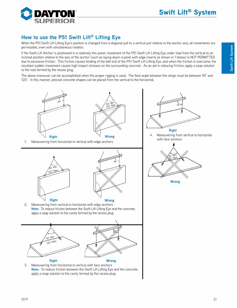
2110/17
Swift Lift® System
Swift
Lift
Sys
tem
How to use the P51 Swift Lift® Lifting EyeWhen the P51 Swift LIft Lifting Eye’s position is changed from a diagonal pull to a vertical pull relative to the anchor axis, all movements are permissible, even with simultaneous rotation.
If the Swift Lift Anchor is positioned in a relatively thin panel, movement of the P51 Swift Lift Lifting Eye under load from the vertical to an inclined position relative to the axis of the anchor (such as laying down a panel with edge inserts as shown in 1 below) is NOT PERMITTED due to excessive friction. This friction causes binding of the ball end of the P51 Swift Lift Lifting Eye, and when the friction is overcome, the resultant sudden movement causes high impact stresses on the surrounding concrete. As an aid in reducing friction, apply a soap solution to the void formed by the recess plug.
The above maneuver can be accomplished when the proper rigging is used. The fleet angle between the slings must be between 90° and 120°. In this manner, precast concrete shapes can be placed from the vertical to the horizontal.
1. Maneuvering from horizontal to vertical with edge anchors
2. Maneuvering from vertical to horizontal with edge anchors Note: To reduce friction between the Swift Lift Lifting Eye and the concrete, apply a soap solution to the cavity formed by the recess plug.
3. Maneuvering from horizontal to vertical with face anchors Note: To reduce friction between the Swift Lift Lifting Eye and the concrete, apply a soap solution to the cavity formed by the recess plug.
4. Maneuvering from vertical to horizontal with face anchors
Right Wrong
Right
Right
Wrong
Wrong
Right Wrong
90°
120° Max.90° Min.
120° Max.
120° Max.
90° Min.
120° Max.90° Min.
90° Min.
90°
90°
90°
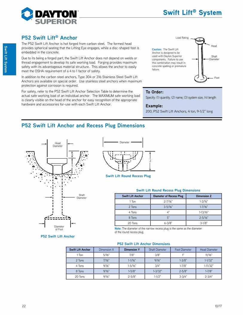
22 10/17
Swift Lift® System
Swift Lift System
P52 Swift Lift Anchor
Head Diameter
X
Y
Shaft Diameter
Diameter of Foot
Swift Lift Round Recess Plug
Z
Diameter
P52 Swift Lift® AnchorThe P52 Swift Lift Anchor is hot forged from carbon steel. The formed head provides spherical seating that the Lifting Eye engages, while a disc-shaped foot is embedded in the concrete.
Due to its being a forged part, the Swift Lift Anchor does not depend on welds or thread engagement to develop its safe working load. Forging provides maximum safety with its advantageous material structure. This allows the anchor to easily meet the OSHA requirement of a 4 to 1 factor of safety.
In addition to the carbon steel anchors, Type 304 or 316 Stainless Steel Swift Lift Anchors are available on special order. Use stainless steel anchors when maximum protection against corrosion is required.
For safety, refer to the P52 Swift Lift Anchor Selection Table to determine the actual safe working load of an individual anchor. The MAXIMUM safe working load is clearly visible on the head of the anchor for easy recognition of the appropriate hardware and accessories for-use with each Swift Lift Anchor.
DS_P52
P52 Swift Lift Anchor and Recess Plug Dimensions
Caution: The Swift Lift Anchor is designed to be used with Dayton Superior components. Failure to use this combination may result in concrete spalling or premature failure.
Load Rating
Head
Shaft Diameter
Foot
4
To Order:Specify: (1) quantity, (2) name, (3) system size, (4) length
Example:200, P52 Swift Lift Anchors, 4 ton, 9-1/2" long
Swift Lift Round Recess Plug DimensionsSwift Lift Anchor Diameter of Recess Plug Dimension Z
1 Ton 2-7/16" 1-3/16"
2 Tons 3-5/16" 1-7/16"
4 Tons 4" 1-13/16"
8 Tons 5" 2-5/16"
20 Tons 6-3/8" 3-1/8"
Note: The diameter of the narrow recess plug is the same as the diameterof the round recess plug.
P52 Swift Lift Anchor DimensionsSwift Lift Anchor Dimension X Dimension Y Shaft Diameter Foot Diameter Head Diameter
1 Ton 5/16" 7/8" 3/8" 1" 11/16"
2 Tons 7/16" 1-1/16" 9/16" 1-3/8" 1-1/32"
4 Tons 9/16" 1-5/16" 3/4" 1-7/8" 1-11/32"
8 Tons 9/16" 1-5/8" 1-3/32" 2-5/8" 1-7/8"
20 Tons 9/16" 2-5/8" 1-1/2" 3-3/4" 2-3/4"
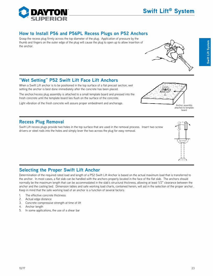
2310/17
Swift Lift® System
Swift
Lift
Sys
tem
How to Install P56 and P56PL Recess Plugs on P52 AnchorsGrasp the recess plug firmly across the top diameter of the plug. Application of pressure by the thumb and fingers on the outer edge of the plug will cause the plug to open up to allow insertion of the anchor.
“Wet Setting” P52 Swift Lift Face Lift AnchorsWhen a Swift Lift anchor is to be positioned in the top surface of a flat precast section, wet setting the anchor is best done immediately after the concrete has been placed.
The anchor/recess plug assembly is attached to a small template board and pressed into the fresh concrete until the template board lies flush on the surface of the concrete.
Light vibration of the fresh concrete will assure proper embedment and anchorage.
Recess Plug RemovalSwift Lift recess plugs provide two holes in the top surface that are used in the removal process. Insert two screw drivers or steel rods into the holes and simply lever the two across the plug for easy removal.
Selecting the Proper Swift Lift AnchorDetermination of the required rated load and length of a P52 Swift Lift Anchor is based on the actual maximum load that is transferred to the anchor. In most cases, a flat slab can be handled with the anchors properly located in the face of the flat slab. The anchors should normally be the maximum length that can be accommodated in the slab’s structural thickness, allowing at least 1/2" clearance between the anchor and the casting bed. Dimension tables and safe working load charts, contained herein, will aid in the selection of the proper anchor. Keep in mind that the safe working load of an anchor is a function of several factors:
1. The effective concrete thickness2. Actual edge distance3. Concrete compressive strength at time of lift4. Anchor length5. In some applications, the use of a shear bar
Anchor assembly attached to template
board

24 10/17
Swift Lift® System
Swift Lift System
P52 Swift Lift® Anchor Tensile and Shear CapacityWhen anchors are used in the face of thin concrete elementsThe following table lists the P52 Swift Lift Anchors that are currently manufactured. Other sizes and lengths are available on special order. However, the sizes and lengths of anchors shown will handle the majority of flat precast concrete elements.
When the P52 Swift Lift Anchor is properly embedded in normal weight concrete, the tabulated working loads are applicable for any direction of load. This applies even if the direction of load is parallel to the axis of the anchor, perpendicular to it or at any other angle.
Minimum distance between anchors is twice the minimum edge distance.
It is critical to remember that in order to obtain the safe working loads listed in the table below, the normal weight concrete must have obtained the minimum concrete strength shown, prior to initial load application.
Minimum
Edge
Distance
Minimum Edge Distance
PV
PD
PT
Swift Lift Anchor Ton x Length Safe Working Load Minimum
Concrete StrengthMinimum
Edge Distance
1 ton x 2-5/8" 1,700 lbs. 3,500 psi 8"
1 ton x 3-3/8" 2,000 lbs. 2,200 psi 10"
1 ton x 4-3/4" 2,000 lbs. 1,600 psi 10"
1 ton x 8" 2,000 lbs. 1,600 psi 10"
1 ton x 9-1/2" 2,000 lbs. 1,600 psi 10"
2 ton x 2-3/4" 2,100 lbs. 3,500 psi 8"
2 ton x 3-3/8" 2,900 lbs. 3,500 psi 10"
2 ton x 4-3/4" 4,000 lbs. 3,500 psi 10"
2 ton x 5-1/2" 4,000 lbs. 1,600 psi 13"
2 ton x 6" 4,000 lbs. 1,600 psi 13"
2 ton x 6-3/4" 4,000 lbs. 1,600 psi 13"
2 ton x 11" 4,000 lbs. 1,600 psi 14"
4 ton x 3-3/4" 4,000 lbs. 3,500 psi 12"
4 ton x 4-1/4" 4,900 lbs. 3,500 psi 13"
4 ton x 4-3/4" 5,800 lbs. 3,500 psi 14"
4 ton x 5-1/2" 7,400 lbs. 3,500 psi 17"
4 ton x 5-3/4" 7,900 lbs. 3,500 psi 17"
4 ton x 7-1/8" 8,000 lbs. 1,800 psi 20"
4 ton x 9-1/2" 8,000 lbs. 1,600 psi 17"
4 ton x 14" 8,000 lbs. 1,600 psi 18"
4 ton x 19" 8,000 lbs. 1,600 psi 20"
8 ton x 4-3/4" 6,400 lbs. 3,500 psi 16"
8 ton x 5-1/4" 6,850 lbs. 3,500 psi 16"
8 ton x 6-3/4" 11,200 lbs. 3,500 psi 21"
8 ton x 10" 16,000 lbs. 3,500 psi 19"
8 ton x 13-3/8" 16,000 lbs. 1,600 psi 23"
8 ton x 26-3/4" 16,000 lbs. 1,600 psi 27"
20 ton x 10" 25,000 lbs. 3,500 psi 24"
20 ton x 19-3/4" 40,000 lbs. 3,500 psi 31"Safe Working Loads provide a factor of safety of approximately 4 to1 in normal weight concrete. Safe Working Load is based on anchor setback from face of concrete “X” dimension, as shown on page 26.
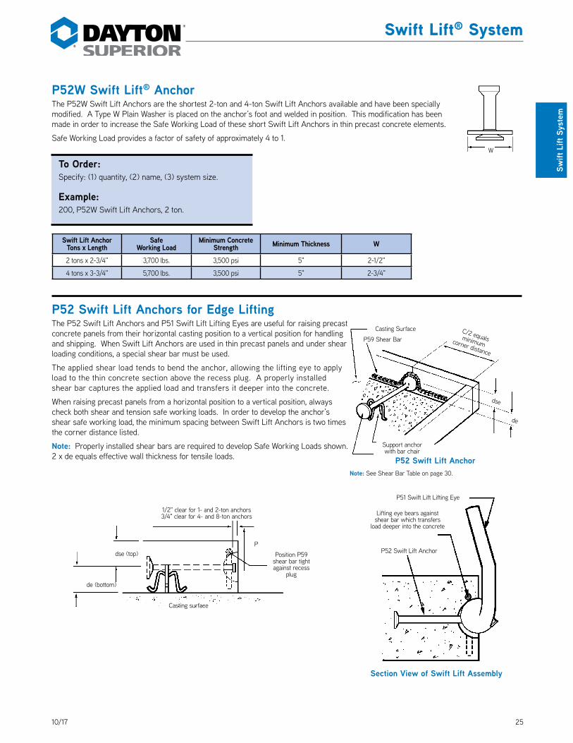
2510/17
Swift Lift® System
Swift
Lift
Sys
tem
P52W Swift Lift® AnchorThe P52W Swift Lift Anchors are the shortest 2-ton and 4-ton Swift Lift Anchors available and have been specially modified. A Type W Plain Washer is placed on the anchor’s foot and welded in position. This modification has been made in order to increase the Safe Working Load of these short Swift Lift Anchors in thin precast concrete elements.
Safe Working Load provides a factor of safety of approximately 4 to 1. DS_P52W
Swift Lift AnchorTons x Length
SafeWorking Load
Minimum ConcreteStrength Minimum Thickness W
2 tons x 2-3/4" 3,700 lbs. 3,500 psi 5" 2-1/2"
4 tons x 3-3/4" 5,700 lbs. 3,500 psi 5" 2-3/4"
P52 Swift Lift Anchors for Edge LiftingThe P52 Swift Lift Anchors and P51 Swift Lift Lifting Eyes are useful for raising precast concrete panels from their horizontal casting position to a vertical position for handling and shipping. When Swift Lift Anchors are used in thin precast panels and under shear loading conditions, a special shear bar must be used.
The applied shear load tends to bend the anchor, allowing the lifting eye to apply load to the thin concrete section above the recess plug. A properly installed shear bar captures the applied load and transfers it deeper into the concrete.
When raising precast panels from a horizontal position to a vertical position, always check both shear and tension safe working loads. In order to develop the anchor’s shear safe working load, the minimum spacing between Swift Lift Anchors is two times the corner distance listed.
Note: Properly installed shear bars are required to develop Safe Working Loads shown. 2 x de equals effective wall thickness for tensile loads.
W
P52 Swift Lift Anchor
Section View of Swift Lift Assembly
Lifting eye bears against shear bar which transfers
load deeper into the concrete
P51 Swift Lift Lifting Eye
de (bottom)
dse (top)P
Casting surface
Position P59 shear bar tight against recess
plug
1/2" clear for 1- and 2-ton anchors3/4" clear for 4- and 8-ton anchors
Casting Surface
P59 Shear Bar
P52 Swift Lift Anchor
dse
C/2 equals minimum corner distance
de
Support anchor with bar chair
Note: See Shear Bar Table on page 30.
To Order:Specify: (1) quantity, (2) name, (3) system size.
Example:200, P52W Swift Lift Anchors, 2 ton.
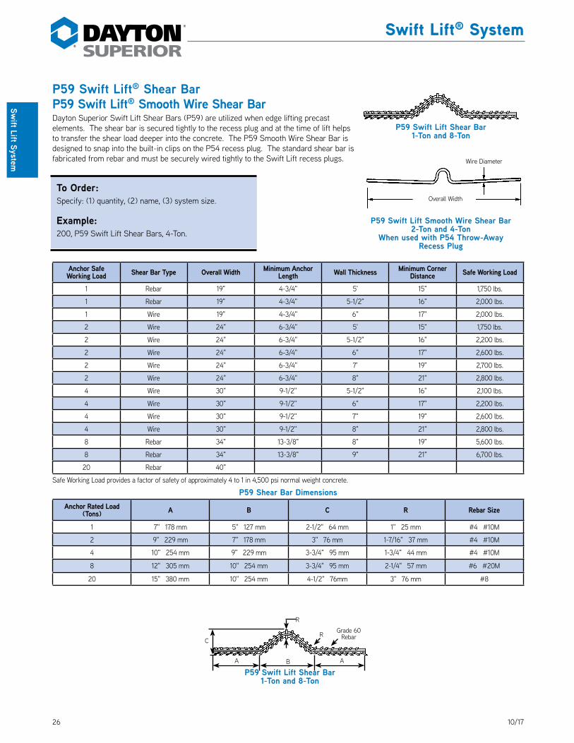
26 10/17
Swift Lift® System
Swift Lift System
P59 Swift Lift® Shear BarP59 Swift Lift® Smooth Wire Shear BarDayton Superior Swift Lift Shear Bars (P59) are utilized when edge lifting precast elements. The shear bar is secured tightly to the recess plug and at the time of lift helps to transfer the shear load deeper into the concrete. The P59 Smooth Wire Shear Bar is designed to snap into the built-in clips on the P54 recess plug. The standard shear bar is fabricated from rebar and must be securely wired tightly to the Swift Lift recess plugs. DS_P59
Anchor Safe Working Load Shear Bar Type Overall Width Minimum Anchor
Length Wall Thickness Minimum Corner Distance Safe Working Load
1 Rebar 19" 4-3/4" 5' 15" 1,750 lbs.
1 Rebar 19" 4-3/4" 5-1/2" 16" 2,000 lbs.
1 Wire 19" 4-3/4" 6" 17" 2,000 lbs.
2 Wire 24" 6-3/4" 5' 15" 1,750 lbs.
2 Wire 24" 6-3/4" 5-1/2" 16" 2,200 lbs.
2 Wire 24" 6-3/4" 6" 17" 2,600 lbs.
2 Wire 24" 6-3/4" 7' 19" 2,700 lbs.
2 Wire 24" 6-3/4" 8" 21" 2,800 lbs.
4 Wire 30" 9-1/2" 5-1/2" 16" 2,100 lbs.
4 Wire 30" 9-1/2" 6" 17" 2,200 lbs.
4 Wire 30" 9-1/2" 7" 19" 2,600 lbs.
4 Wire 30" 9-1/2" 8" 21" 2,800 lbs.
8 Rebar 34" 13-3/8" 8" 19" 5,600 lbs.
8 Rebar 34" 13-3/8" 9" 21" 6,700 lbs.
20 Rebar 40"
Safe Working Load provides a factor of safety of approximately 4 to 1 in 4,500 psi normal weight concrete.
P59 Shear Bar DimensionsAnchor Rated Load
(Tons) A B C R Rebar Size
1 7" 178 mm 5" 127 mm 2-1/2" 64 mm 1" 25 mm #4 #10M
2 9" 229 mm 7" 178 mm 3" 76 mm 1-7/16" 37 mm #4 #10M
4 10" 254 mm 9" 229 mm 3-3/4" 95 mm 1-3/4" 44 mm #4 #10M
8 12" 305 mm 10" 254 mm 3-3/4" 95 mm 2-1/4" 57 mm #6 #20M
20 15" 380 mm 10" 254 mm 4-1/2" 76mm 3" 76 mm #8
Wire Diameter
Overall Width
P59 Swift Lift Smooth Wire Shear Bar2-Ton and 4-Ton
When used with P54 Throw-Away Recess Plug
To Order:Specify: (1) quantity, (2) name, (3) system size.
Example:200, P59 Swift Lift Shear Bars, 4-Ton.
P59 Swift Lift Shear Bar1-Ton and 8-Ton
P59 Swift Lift Shear Bar1-Ton and 8-Ton
Grade 60 Rebar
R
R
B
C
A A

2710/17
Swift Lift® System
Swift
Lift
Sys
tem
P52 Swift Lift® Anchor in Thin WallsThe P52 Swift Lift Anchors, listed below, must be located the minimum distance away from a corner with the anchor foot being positioned at the center line of the wall. The anchor head location may be off center, however, any eccentricity of the foot will result in a reduction of the safe working load. When the anchor foot is not positioned at the center line of the wall, the effective wall thickness is equal to twice the actual edge distance.
To develop the safe working load of the P52 Swift Lift Anchor, the minimum spacing between two anchors is six times the anchor length.
Swift Lift® Anchor Effective Tensile Capacity in Thin WallsSwift Lift Anchor
Ton x LengthEffective Wall Thicness 2 de
Actual Edge Distance
de
Tensile Safe Working Load per Anchor Actual Corner Distance
6" 12" 18" 24" 30"
1 Ton x
4-3/4" Long
2-1/2" 1-1/4" 900 lbs. 1,100 lbs. 1,200 lbs. 1,200 lbs. 1,200 lbs.
2-3/4" 1-3/8" 1,000 lbs. 1,200 lbs. 1,300 lbs. 1,300 lbs. 1,300 lbs.
3" 1-1/2" 1,100 lbs. 1,300 lbs. 1,400 lbs. 1,400 lbs. 1,400 lbs.
3-1/2" 1-3/4" 1,200 lbs. 1,600 lbs. 1,600 lbs. 1,600 lbs. 1,600 lbs.
4" 2" 1,450 lbs. 1,800 lbs. 1,900 lbs. 1,900 lbs. 1,900 lbs.
4-1/2" 2-1/4" 1,600 lbs. 2,000 lbs. 2,000 lbs. 2,000 lbs. 2,000 lbs.
1 Ton x
9-1/2" Long
2-1/2" 1-1/4" 1,300 lbs. 1,700 lbs. 1,900 lbs. 1,900 lbs. 1,900 lbs.
2-3/4" 1-3/8" 1,400 lbs. 1,900 lbs. 2,000 lbs. 2,000 lbs. 2,000 lbs.
3" 1-1/2" 1,500 lbs. 2,000 lbs. 2,000 lbs. 2,000 lbs. 2,000 lbs.
3-1/2" 1-3/4" 1,800 lbs. 2,000 lbs. 2,000 lbs. 2,000 lbs. 2,000 lbs.
4" 2" 2,000 lbs. 2,000 lbs. 2,000 lbs. 2,000 lbs. 2,000 lbs.
4-1/2" 2-1/4" 2,000 lbs. 2,000 lbs. 2,000 lbs. 2,000 lbs. 2,000 lbs.
Safe Working Load provides a factor of safety of approximately 4 to 1 in 4,500 psi normal weight concrete.
Wall center
line
Effective Wall ThicknessEffective
Wall Thickness
Actual Wall Thickness
P PP
L = P52 Anchor Length
Center Line of Anchor Foot
and Wall
Corner Distance
de = Actual Edge DistanceWall Thickness
de de de
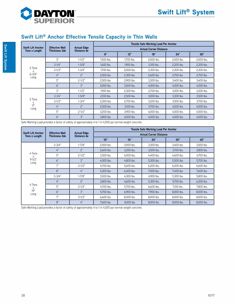
28 10/17
Swift Lift® System
Swift Lift System
Swift Lift® Anchor Effective Tensile Capacity in Thin Walls
Swift Lift Anchor Tons x Length
Effective Wall Thickness 2de
Actual Edge Distance de
Tensile Safe Working Load Per AnchorActual Corner Distance
8" 12" 18" 24" 30"
2 Tonsx
6-3/4"Long
3" 1-1/2" 1,500 lbs. 1,700 lbs. 2,000 lbs. 2,000 lbs. 2,000 lbs.
3-1/4" 1-5/8" 1,600 lbs. 1,900 lbs. 2,100 lbs. 2,200 lbs. 2,200 lbs.
3-1/2" 1-3/4" 1,700 lbs. 2,000 lbs. 2,300 lbs. 2,300 lbs. 2,300 lbs.
4" 2" 2,000 lbs. 2,300 lbs. 2,600 lbs. 2,700 lbs. 2,700 lbs.
5" 2-1/2" 2,500 lbs. 2,900 lbs. 3,300 lbs. 3,400 lbs. 3,400 lbs.
6" 3" 3,000 lbs. 3,500 lbs. 4,000 lbs. 4,000 lbs. 4,000 lbs.
2 Tonsx
11"Long
3" 1-1/2" 1,900 lbs. 2,300 lbs. 2,700 lbs. 3,000 lbs. 3,200 lbs.
3-1/4" 1-5/8" 2,100 lbs. 2,500 lbs. 3,000 lbs. 3,300 lbs. 3,500 lbs.
3-1/2" 1-3/4" 2,200 lbs. 2,700 lbs. 3,200 lbs. 3,500 lbs. 3,700 lbs.
4" 2" 2,500 lbs. 3,100 lbs. 3,700 lbs. 4,000 lbs. 4,000 lbs.
5" 2-1/2" 3,200 lbs. 3,900 lbs. 4,000 lbs. 4,000 lbs. 4,000 lbs.
6" 3" 3,800 lbs. 4,000 lbs. 4,000 lbs. 4,000 lbs. 4,000 lbs.
Safe Working Load provides a factor of safety of approximately 4 to 1 in 4,500 psi normal weight concrete.
Swift Lift Anchor Tons x Length
Effective Wall Thickness 2de
Actual Edge Distance de
Tensile Safe Working Load Per AnchorActual Corner Distance
10" 16" 24" 30" 42"
4 Tonsx
9-1/2"Long
3-3/4" 1-7/8" 2,500 lbs. 3,000 lbs. 3,300 lbs. 3,400 lbs. 3,500 lbs.
4" 2" 2,600 lbs. 3,200 lbs. 3,500 lbs. 3,700 lbs. 3,800 lbs.
5" 2-1/2" 3,300 lbs. 4,000 lbs. 4,400 lbs. 4,600 lbs. 4,700 lbs.
6" 3" 4,000 lbs. 4,800 lbs. 5,300 lbs. 5,500 lbs. 5,700 lbs.
7" 3-1/2" 4,700 lbs. 5,600 lbs. 6,200 lbs. 6,500 lbs. 6,600 lbs.
8" 4" 5,300 lbs. 6,400 lbs. 7,000 lbs. 7,400 lbs. 7,600 lbs.
4 Tonsx
19"Long
3-3/4" 1-7/8" 3,500 lbs. 4,300 lbs. 4,900 lbs. 5,300 lbs. 5,800 lbs.
4" 2" 3,800 lbs. 4,600 lbs. 5,300 lbs. 5,700 lbs. 6,200 lbs.
5" 2-1/2" 4,700 lbs. 5,700 lbs. 6,600 lbs. 7,100 lbs. 7,800 lbs.
6" 3" 5,700 lbs. 6,900 lbs. 7,900 lbs. 8,000 lbs. 8,000 lbs.
7" 3-1/2" 6,600 lbs. 8,000 lbs. 8,000 lbs. 8,000 lbs. 8,000 lbs.
8" 4" 7,600 lbs. 8,000 lbs 8,000 lbs. 8,000 lbs. 8,000 lbs.
Safe Working Load provides a factor of safety of approximately 4 to 1 in 4,500 psi normal weight concrete.
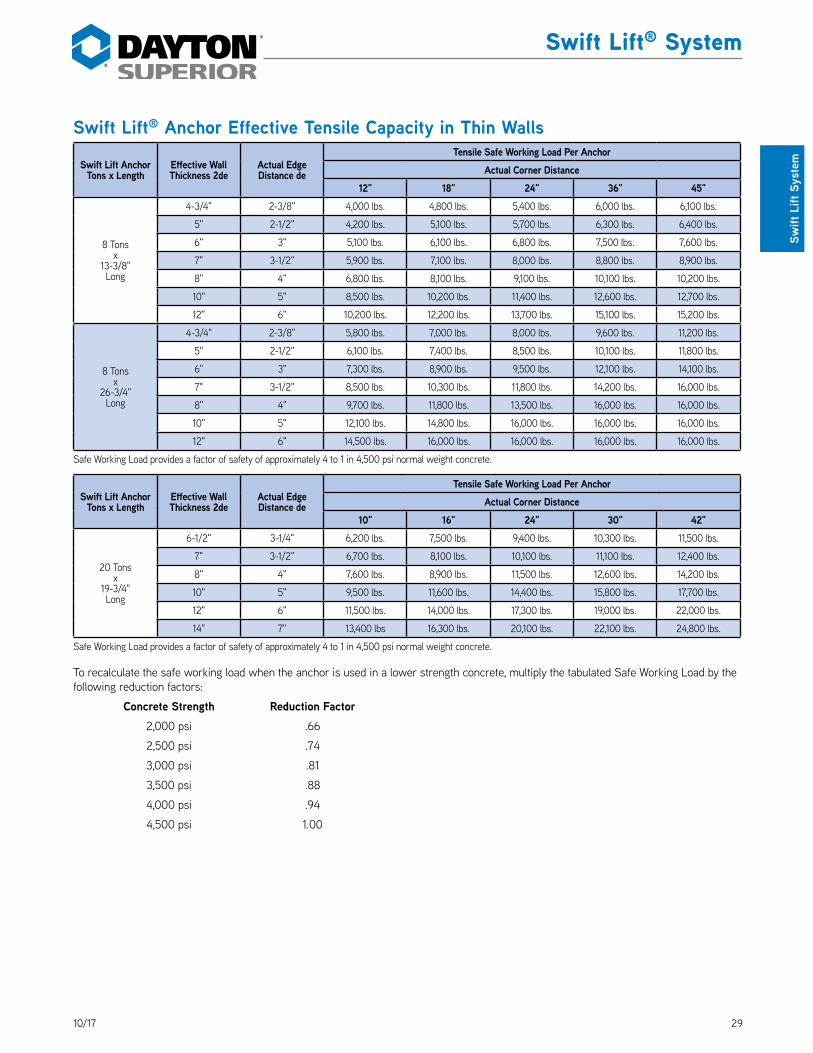
2910/17
Swift Lift® System
Swift
Lift
Sys
tem
Swift Lift® Anchor Effective Tensile Capacity in Thin Walls
Swift Lift Anchor Tons x Length
Effective Wall Thickness 2de
Actual Edge Distance de
Tensile Safe Working Load Per AnchorActual Corner Distance
12" 18" 24" 36" 45"
8 Tonsx
13-3/8"Long
4-3/4" 2-3/8" 4,000 lbs. 4,800 lbs. 5,400 lbs. 6,000 lbs. 6,100 lbs.
5" 2-1/2" 4,200 lbs. 5,100 lbs. 5,700 lbs. 6,300 lbs. 6,400 lbs.
6" 3" 5,100 lbs. 6,100 lbs. 6,800 lbs. 7,500 lbs. 7,600 lbs.
7" 3-1/2" 5,900 lbs. 7,100 lbs. 8,000 lbs. 8,800 lbs. 8,900 lbs.
8" 4" 6,800 lbs. 8,100 lbs. 9,100 lbs. 10,100 lbs. 10,200 lbs.
10" 5" 8,500 lbs. 10,200 lbs. 11,400 lbs. 12,600 lbs. 12,700 lbs.
12" 6" 10,200 lbs. 12,200 lbs. 13,700 lbs. 15,100 lbs. 15,200 lbs.
8 Tonsx
26-3/4"Long
4-3/4" 2-3/8" 5,800 lbs. 7,000 lbs. 8,000 lbs. 9,600 lbs. 11,200 lbs.
5" 2-1/2" 6,100 lbs. 7,400 lbs. 8,500 lbs. 10,100 lbs. 11,800 lbs.
6" 3" 7,300 lbs. 8,900 lbs. 9,500 lbs. 12,100 lbs. 14,100 lbs.
7" 3-1/2" 8,500 lbs. 10,300 lbs. 11,800 lbs. 14,200 lbs. 16,000 lbs.
8" 4" 9,700 lbs. 11,800 lbs. 13,500 lbs. 16,000 lbs. 16,000 lbs.
10" 5" 12,100 lbs. 14,800 lbs. 16,000 lbs. 16,000 lbs. 16,000 lbs.
12" 6" 14,500 lbs. 16,000 lbs. 16,000 lbs. 16,000 lbs. 16,000 lbs.
Safe Working Load provides a factor of safety of approximately 4 to 1 in 4,500 psi normal weight concrete.
Swift Lift Anchor Tons x Length
Effective Wall Thickness 2de
Actual Edge Distance de
Tensile Safe Working Load Per AnchorActual Corner Distance
10" 16" 24" 30" 42"
20 Tonsx
19-3/4"Long
6-1/2" 3-1/4" 6,200 lbs. 7,500 lbs. 9,400 lbs. 10,300 lbs. 11,500 lbs.
7" 3-1/2" 6,700 lbs. 8,100 lbs. 10,100 lbs. 11,100 lbs. 12,400 lbs.
8" 4" 7,600 lbs. 8,900 lbs. 11,500 lbs. 12,600 lbs. 14,200 lbs.
10" 5" 9,500 lbs. 11,600 lbs. 14,400 lbs. 15,800 lbs. 17,700 lbs.
12" 6" 11,500 lbs. 14,000 lbs. 17,300 lbs. 19,000 lbs. 22,000 lbs.
14" 7" 13,400 lbs 16,300 lbs. 20,100 lbs. 22,100 lbs. 24,800 lbs.
Safe Working Load provides a factor of safety of approximately 4 to 1 in 4,500 psi normal weight concrete.
To recalculate the safe working load when the anchor is used in a lower strength concrete, multiply the tabulated Safe Working Load by the following reduction factors:
Concrete Strength Reduction Factor 2,000 psi .66
2,500 psi .74
3,000 psi .81
3,500 psi .88
4,000 psi .94
4,500 psi 1.00

30 10/17
Swift Lift® System
Swift Lift System
Swift Lift® Anchor Effective Tensile CapacityWhen anchors are used in groups and in thin walls
Swift Lift Anchor Tons x Length
Effective Wall Thickness 2de
Actual Edge Distance de
Tensile Safe Working Load Per AnchorActual Corner Distance
18" 24" 30" 36" 48"
2 Tonsx
6-3/4"Long
3" 1-1/2" 1,200 lbs. 1,500 lbs. 1,800 lbs. 1,900 lbs. 2,000 lbs.
3-1/4" 1-5/8" 1,300 lbs. 1,700 lbs. 1,900 lbs. 2,100 lbs. 2,200 lbs.
3-1/2" 1-3/4" 1,400 lbs. 1,800 lbs. 2,100 lbs. 2,300 lbs. 2,400 lbs.
4" 2" 1,600 lbs. 2,100 lbs. 2,400 lbs. 2,600 lbs. 2,700 lbs.
5" 2-1/2" 2,000 lbs. 2,600 lbs. 3,000 lbs. 3,200 lbs. 3,400 lbs.
6" 3" 2,500 lbs. 3,100 lbs. 3,600 lbs. 3,900 lbs. 4,000 lbs.
2 Tonsx
11"Long
3" 1-1/2" 1,300 lbs. 1,700 lbs. 2,000 lbs. 2,300 lbs. 2,900 lbs.
3-1/4" 1-5/8" 1,400 lbs. 1,800 lbs. 2,200 lbs. 2,500 lbs. 3,100 lbs.
3-1/2" 1-3/4" 1,500 lbs. 1,900 lbs. 2,400 lbs. 2,700 lbs. 3,300 lbs.
4" 2" 1,700 lbs. 2,200 lbs. 2,700 lbs. 3,100 lbs. 3,800 lbs.
5" 2-1/2" 2,100 lbs. 2,800 lbs. 3,400 lbs. 3,900 lbs. 4,000 lbs.
6" 3" 2,600 lbs. 3,400 lbs. 4,000 lbs. 4,000 lbs. 4,000 lbs.
Safe Working Load provides a factor of safety of approximately 4 to 1 in 4,500 psi normal weight concrete.
Swift Lift Anchor Tons x Length
Effective Wall Thickness 2de
Actual Edge Distance de
Tensile Safe Working Load Per AnchorActual Corner Distance
18" 24" 36" 48" 60"
4 Tonsx
9-1/2"Long
3-3/4" 1-7/8" 1,600 lbs. 2,000 lbs. 2,800 lbs. 3,300 lbs. 3,500 lbs.
4" 2" 1,700 lbs. 2,200 lbs. 3,000 lbs. 3,600 lbs. 3,800 lbs.
5" 2-1/2" 2,100 lbs. 2,700 lbs. 3,800 lbs. 4,500 lbs. 4,700 lbs.
6" 3" 2,500 lbs. 3,300 lbs. 4,600 lbs. 5,400 lbs. 5,700 lbs.
7" 3-1/2" 3,000 lbs. 3,900 lbs. 5,300 lbs. 6,300 lbs. 6,700 lbs.
8" 4" 3,400 lbs. 4,400 lbs. 6,100 lbs. 7,200 lbs. 7,600 lbs.
4 Tonsx
19"Long
3-3/4" 1-7/8" 1,600 lbs. 2,200 lbs. 3,200 lbs. 4,100 lbs. 5,000 lbs.
4" 2" 1,700 lbs. 2,300 lbs. 3,400 lbs. 4,400 lbs. 5,300 lbs.
5" 2-1/2" 2,200 lbs. 2,900 lbs. 4,300 lbs. 5,500 lbs. 6,600 lbs.
6" 3" 2,600 lbs. 3,500 lbs. 5,100 lbs. 6,600 lbs. 8,000 lbs.
7" 3-1/2" 3,100 lbs. 4,100 lbs. 6,000 lbs. 7,700 lbs. 8,000 lbs.
8" 4" 3,500 lbs. 4,500 lbs. 6,800 lbs. 8,000 lbs. 8,000 lbs.
Safe Working Load provides a factor of safety of approximately 4 to 1 in 4,500 psi normal weight concrete.

3110/17
Swift Lift® System
Swift
Lift
Sys
tem
Swift Lift® Anchor Effective Tensile CapacityWhen anchors are used in groups and in thin walls
Swift Lift Anchor Tons x Length
Effective Wall Thickness 2de
Actual Edge Distance de
Tensile Safe Working Load Per AnchorActual Corner Distance
12" 18" 24" 36" 45"
8 Tonsx
13-3/8"Long
4-3/4" 2-3/8" 2,800 lbs. 3,600 lbs. 4,800 lbs. 5,300 lbs. 5,300 lbs.
5" 2-1/2" 2,900 lbs. 3,800 lbs. 5,000 lbs. 5,600 lbs. 5,600 lbs.
6" 3" 3,500 lbs. 4,500 lbs. 6,000 lbs. 6,700 lbs. 6,700 lbs.
7" 3-1/2" 4,100 lbs. 5,300 lbs. 7,100 lbs. 7,800 lbs. 7,800 lbs.
8" 4" 4,700 lbs. 6,000 lbs. 8,100 lbs. 8,900 lbs. 8,900 lbs.
10" 5" 5,900 lbs. 7,500 lbs. 10,100 lbs. 11,200 lbs. 11,200 lbs.
12" 5-1/2" 6,500 lbs. 8,300 lbs. 11,000 lbs. 12,300 lbs. 12,300 lbs.
8 Tonsx
26-3/4"Long
4-3/4" 2-3/8" 2,900 lbs. 3,800 lbs. 5,600 lbs. 7,200 lbs. 8,500 lbs.
5" 2-1/2" 3,100 lbs. 4,000 lbs. 5,900 lbs. 7,600 lbs. 9,000 lbs.
6" 3" 3,700 lbs. 4,800 lbs. 7,100 lbs. 9,100 lbs. 10,800 lbs.
7" 3-1/2" 4,300 lbs. 5,700 lbs. 8,300 lbs. 10,600 lbs. 12,500 lbs.
8" 4" 4,900 lbs. 6,500 lbs. 9,400 lbs. 12,100 lbs. 14,300 lbs.
10" 5" 6,100 lbs. 8,100 lbs. 11,800 lbs. 15,100 lbs. 16,000 lbs.
12" 5-1/2" 6,700 lbs. 8,900 lbs. 13,000 lbs. 16,000 lbs. 16,000 lbs.
Safe Working Load provides a factor of safety of approximately 4 to 1 in 4,500 psi normal weight concrete.
Swift Lift Anchor Tons x Length
Effective Wall Thickness 2de
Actual Edge Distance de
Tensile Safe Working Load Per AnchorActual Corner Distance
10" 16" 24" 30" 42"
20 Tonsx
19-3/4"Long
6-1/2" 3-1/4" 4,300 lbs. 5,200 lbs. 6,800 lbs. 8,300 lbs. 10,200 lbs.
7" 3-1/2" 4,700 lbs. 5,600 lbs. 7,400 lbs. 8,900 lbs. 11,000 lbs.
8" 4" 5,400 lbs. 6,300 lbs. 8,400 lbs. 10,200 lbs. 12,600 lbs.
10" 5" 6,700 lbs. 7,900 lbs. 10,500 lbs. 12,700 lbs. 15,700 lbs.
12" 6" 8,000 lbs. 9,500 lbs. 12,600 lbs. 15,300 lbs. 18,900 lbs.
14" 7" 9,300 lbs. 11,100 lbs. 14,700 lbs. 17,800 lbs. 22,000 lbs.
Safe Working Load provides a factor of safety of approximately 4 to 1 in 4,500 psi normal weight concrete.
To recalculate the safe working load when the anchor is used in a lower strength concrete, multiply the tabulated Safe Working Load by the following reduction factors:
Concrete Strength Reduction Factor 2,000 psi .66
2,500 psi .74
3,000 psi .81
3,500 psi .88
4,000 psi .94
4,500 psi 1.00
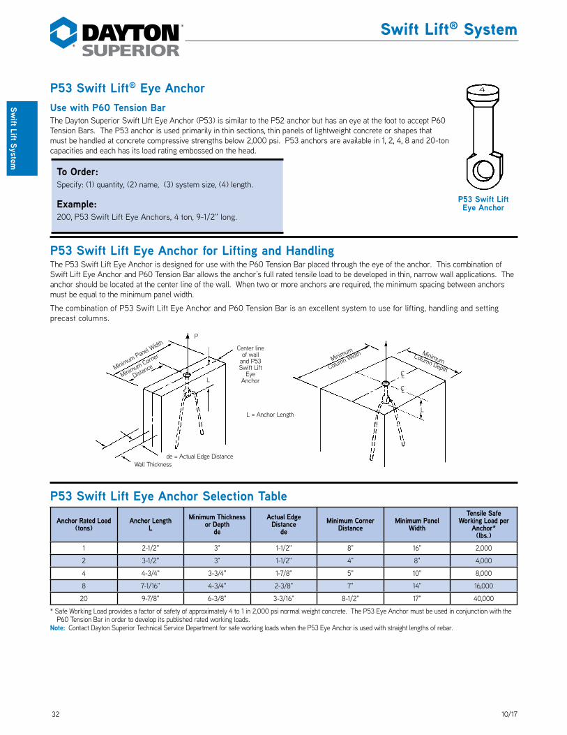
32 10/17
Swift Lift® System
Swift Lift System
P53 Swift Lift® Eye AnchorUse with P60 Tension BarThe Dayton Superior Swift LIft Eye Anchor (P53) is similar to the P52 anchor but has an eye at the foot to accept P60 Tension Bars. The P53 anchor is used primarily in thin sections, thin panels of lightweight concrete or shapes that must be handled at concrete compressive strengths below 2,000 psi. P53 anchors are available in 1, 2, 4, 8 and 20-ton capacities and each has its load rating embossed on the head. DS_P53
P53 Swift Lift Eye Anchor for Lifting and HandlingThe P53 Swift Lift Eye Anchor is designed for use with the P60 Tension Bar placed through the eye of the anchor. This combination of Swift Lift Eye Anchor and P60 Tension Bar allows the anchor’s full rated tensile load to be developed in thin, narrow wall applications. The anchor should be located at the center line of the wall. When two or more anchors are required, the minimum spacing between anchors must be equal to the minimum panel width.
The combination of P53 Swift Lift Eye Anchor and P60 Tension Bar is an excellent system to use for lifting, handling and setting precast columns.
P53 Swift Lift Eye Anchor Selection Table
Anchor Rated Load(tons)
Anchor Length L
Minimum Thickness or Depth
de
Actual Edge Distance
deMinimum Corner
DistanceMinimum Panel
Width
Tensile Safe Working Load per
Anchor*(lbs.)
1 2-1/2" 3" 1-1/2" 8" 16" 2,000
2 3-1/2" 3" 1-1/2" 4" 8" 4,000
4 4-3/4" 3-3/4" 1-7/8" 5" 10" 8,000
8 7-1/16" 4-3/4" 2-3/8" 7" 14" 16,000
20 9-7/8" 6-3/8" 3-3/16" 8-1/2" 17" 40,000
* Safe Working Load provides a factor of safety of approximately 4 to 1 in 2,000 psi normal weight concrete. The P53 Eye Anchor must be used in conjunction with the P60 Tension Bar in order to develop its published rated working loads.
Note: Contact Dayton Superior Technical Service Department for safe working loads when the P53 Eye Anchor is used with straight lengths of rebar.
Minimum Panel Width
Minimum
Column Width Minimum Column Depth
Minimum Corner
Distance
P
L
de = Actual Edge DistanceWall Thickness
L = Anchor Length
Center line of wall
and P53 Swift Lift
Eye Anchor
L
CL
CL
P53 Swift Lift Eye Anchor
4
To Order:Specify: (1) quantity, (2) name, (3) system size, (4) length.
Example:200, P53 Swift Lift Eye Anchors, 4 ton, 9-1/2" long.
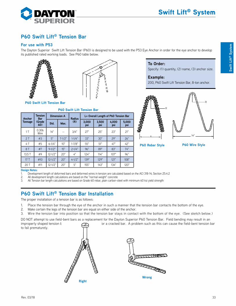
3310/17
Swift Lift® System
Swift
Lift
® S
yste
m
P60 Swift Lift® Tension BarFor use with P53The Dayton Superior Swift Lift Tension Bar (P60) is designed to be used with the P53 Eye Anchor in order for the eye anchor to develop its published rated working loads. See P60 table below. DS_P60
P60 Swift Lift Tension Bar
Anchor Tonnage
Tension Bar
(Grade 60)
Dimension ARadius
(R)
L= Overall Length of P60 Tension Bar
Std. Max. 3,000 psi
3,500 psi
4,000 psi
5,000 psi
1 T 0.306 Wire 14" — 3/4" 27" 25" 23" 21"
2 T #3 5" 7-1/2" 1-1/4" 33" 30" 29" 26"
4 T #5 6-1/4" 10" 1-7/8" 55" 51" 47" 42"
8 T #7 9-1/2" 15" 2-1/4" 96" 89" 83" 74"
13.5 T #9 12-1/2" 20" 4" 124" 114" 107" 96"
17 T #10 12-1/2" 20" 4-1/2" 139" 129" 121" 108"
20 T #11 12-1/2" 20" 5" 155" 143" 134" 120"
Design Notes:1. Development length of deformed bars and deformed wires in tension are calculated based on the ACI 318-14, Section 25.4.22. All development length calculations are based on the "normal weight" concrete3. All Tension bar length calculations are based on Grade 60 rebar, plain carbon-steel with minimum 60 ksi yield strength
P60 Swift Lift® Tension Bar InstallationThe proper installation of a tension bar is as follows:
1. Place the tension bar through the eye of the anchor in such a manner that the tension bar contacts the bottom of the eye.2. Make certain the legs of the tension bar are equal on either side of the anchor.3. Wire the tension bar into position so that the tension bar stays in contact with the bottom of the eye. (See sketch below.)
DO NOT attempt to use field-bent bars as a replacement for the Dayton Superior P60 Tension Bar. Field bending may result in an improperly shaped tension bar, an incorrect radius and/or a cracked bar. A problem such as this can cause the field-bent tension bar to fail prematurely.
P60 Swift Lift Tension Bar
RightWrong
A
R
P60 Rebar Style
R
14"
P60 Wire Style
To Order:Specify: (1) quantity, (2) name, (3) anchor size.
Example:200, P60 Swift Lift Tension Bar, 8-ton anchor.
Rev. 03/18

34 10/17
Swift Lift® System
Swift Lift System
P54 Swift Lift® Throw-Away Recess PlugThe Dayton Superior P54 Recess Plug is fabricated from high-density polyethylene plastic in two sizes (2-ton and 4-ton) to accommodate the P52 Swift Lift Anchor. The two-piece design snaps together around the head of the anchor to securely grasp the anchor. Tabs on the recess plug provide a convenient method to nail the assembly to the form. Built-in retainers allow a P59 Shear Bar to clip to the recess plug and be held in correct position. The P54 recess plug is designed to properly position the anchor below the surface of the concrete. This allows easy patching of the recess and prevents surface staining from exposed steel. DS_P54
Warning: The P54 recess plug is designed to be used with the P52 insert and P59 shear bar combination. Failure to use these components in this combination may result in concrete spalling and/or premature failure.
3" for 9/16" Diameter Anchors
3-3/4" for 3/4" Diameter Anchors
P54 Swift Lift Recess Plug
Anchor Head
P52 Swift Lift Anchor
Anchor Foot
1. Assemble the P54 Recess Plug by placing the head of the P52 Swift-Lift Anchor inside two halves of the recess plug. Then snap the two halves together. It is very difficult to assemble the unit with the foot of the anchor inside the P54 Recess Plug and still get the two halves to close together correctly. If the two halves of the P54 Recess Plug do not fit closely together, it could be because the anchor is in upside down. In such a case, reverse the anchor and try again.
Anchor Foot
2. A correctly assembled P54 Recess Plug and P52 Swift Lift Anchor.
3. Attach the assembled P54 Recess Plug and anchor to the form work in its predetermined location with the recess plug seam in the vertical position. Use common (not double headed) nails in the upper three tabs of the recess plug. The plug and anchor assembly can also be attached to the form work by using a 2-ton stud and wingnut if desired. Provide bar supports around the anchor, as shown, to prevent displacement during the casting process.
4. Slip the preformed shear bar on the P54 Recess Plug, as shown. The receiving tabs of the P54 Recess Plug will correctly position the shear bar. Usually, additional support wiring is not needed to hold the shear bar in place. However, prudent users will provide an additional wire tie or two, to make certain the shear bar will not dislodge during concrete placement. Wire tie the P52 Swift-Lift Anchor to reinforcing steel, as shown.
To Order:Specify: (1) quantity, (2) name, (3) anchor size.
Example:200, P54 Swift Lift Recess Plugs, 4-ton anchor.
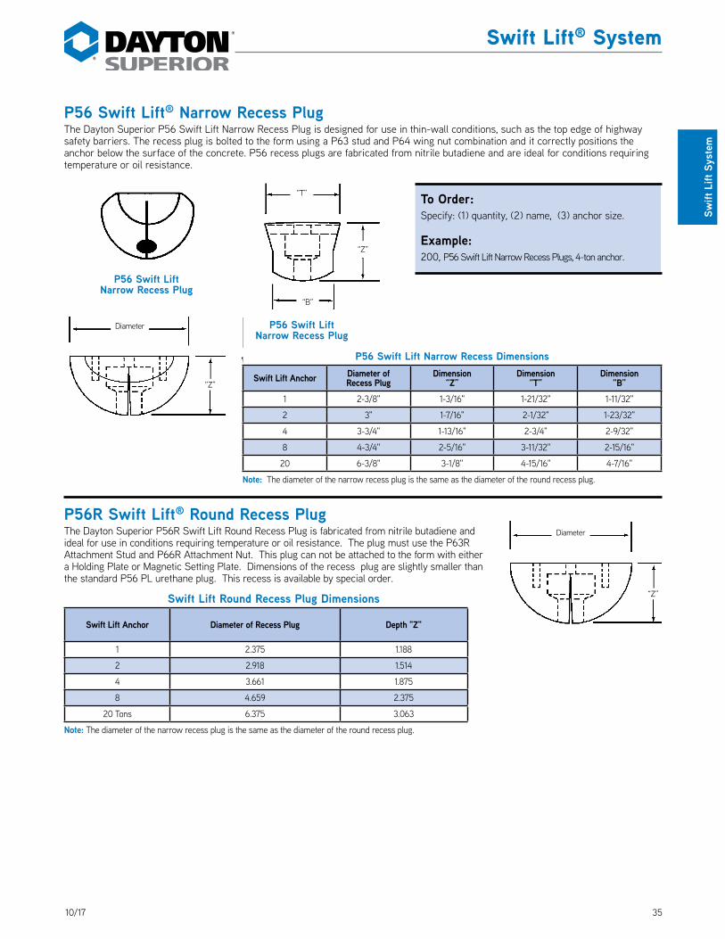
3510/17
Swift Lift® System
Swift
Lift
Sys
tem
P56 Swift Lift® Narrow Recess PlugThe Dayton Superior P56 Swift Lift Narrow Recess Plug is designed for use in thin-wall conditions, such as the top edge of highway safety barriers. The recess plug is bolted to the form using a P63 stud and P64 wing nut combination and it correctly positions the anchor below the surface of the concrete. P56 recess plugs are fabricated from nitrile butadiene and are ideal for conditions requiring temperature or oil resistance. DS_P56
P56 Swift Lift Narrow Recess Dimensions
Swift Lift Anchor Diameter ofRecess Plug
Dimension“Z”
Dimension“T”
Dimension“B”
1 2-3/8" 1-3/16" 1-21/32" 1-11/32"
2 3" 1-7/16" 2-1/32" 1-23/32"
4 3-3/4" 1-13/16" 2-3/4" 2-9/32"
8 4-3/4" 2-5/16" 3-11/32" 2-15/16"
20 6-3/8" 3-1/8" 4-15/16" 4-7/16"
Note: The diameter of the narrow recess plug is the same as the diameter of the round recess plug.
P56R Swift Lift® Round Recess PlugThe Dayton Superior P56R Swift Lift Round Recess Plug is fabricated from nitrile butadiene and ideal for use in conditions requiring temperature or oil resistance. The plug must use the P63R Attachment Stud and P66R Attachment Nut. This plug can not be attached to the form with either a Holding Plate or Magnetic Setting Plate. Dimensions of the recess plug are slightly smaller than the standard P56 PL urethane plug. This recess is available by special order. DS_P56R
Swift Lift Round Recess Plug Dimensions
Swift Lift Anchor Diameter of Recess Plug Depth "Z"
1 2.375 1.188
2 2.918 1.514
4 3.661 1.875
8 4.659 2.375
20 Tons 6.375 3.063
Note: The diameter of the narrow recess plug is the same as the diameter of the round recess plug.
Diameter
“Z”
“Z”
Diameter
P56 Swift Lift Narrow Recess Plug
P56 Swift Lift Narrow Recess Plug
“T”
“Z”
“B”
To Order:Specify: (1) quantity, (2) name, (3) anchor size.
Example:200, P56 Swift Lift Narrow Recess Plugs, 4-ton anchor.

36 10/17
Swift Lift® System
Swift Lift System
P56PL Swift Lift® Plus Recess PlugThe Dayton Superior P56PL Swift Lift Plus Recess Plug is manufactured from high-grade elastomeric, thermal set urethane to provide improved tear, heat and chemical resistance. The versatile, reusable plug utilizes a variety of accessories to provide installation and stripping ease in many different applications. P56PL recess plugs are available for 1, 2, 4 and 8-ton system sizes. See dimensions of P56PL Recess Plug in P52 information. DS_P56PL
P57 Swift Lift® Steel Recess Plug
P58 Swift Lift® Rubber RingThe Dayton Superior P57 Swift Lift Steel Recess Plug is designed for permanent or semi-permanent attachment to repetitive-use precast forms, such as battery molds, steel forms that have a collapsible stripping feature, etc. The recess plug is drilled and tapped for easy attachment to the form or may be held in place by a magnetic plate, tack welded or glued. Available in 1, 2 and 4-ton only. DS_P57
The P58 Swift Lift Rubber Ring is placed on the shaft of the anchor and seats in the recess plug to hold the anchor firmly in the recess plug. It is recommended that when the P57 recess plug is used, the anchor end be supported to prevent dislodging (See sketch below). DS_P58
P56PL Swift Lift Plus Recess Plug
P57 Swift Lift Steel Recess
Plug
P58 Swift Lift Rubber Ring
Tie Wire To Nearby Reinforcing Steel
Form Face
P56PL Swift Lift Plus Recess Plug Typical Installations
Holding Plate P68PL
Recess Plug P56PL
Recess Plug P56PL
Recess Plug P56PL
Stud Plate P67PL
Coil Wing Nut P64PL
Tapped Plate P66PL
Holding Plate (Optional)
P68PL
Holding Stud With Wing Nut P63PL
Free Running
Nut
Fixed Nut
Swift Lift Anchor REF
Swift Lift Anchor REF
Swift Lift Anchor REF
To Order:Specify: (1) quantity, (2) name, (3) anchor size.
Example:200, P54PL Swift Lift Plus Recess Plugs, 4-Ton anchor.
P57 Swift Lift Steel Recess Plug
P58 Swift Lift Rubber Ring for Steel Recess Plug
To Order:Specify: (1) quantity, (2) name, (3) anchor size.
Example:200, P57 Swift Lift Steel Recess Plugs, 4-Ton anchor and 400 P58 Swift Lift Rubber Rings for 4-Ton anchors.
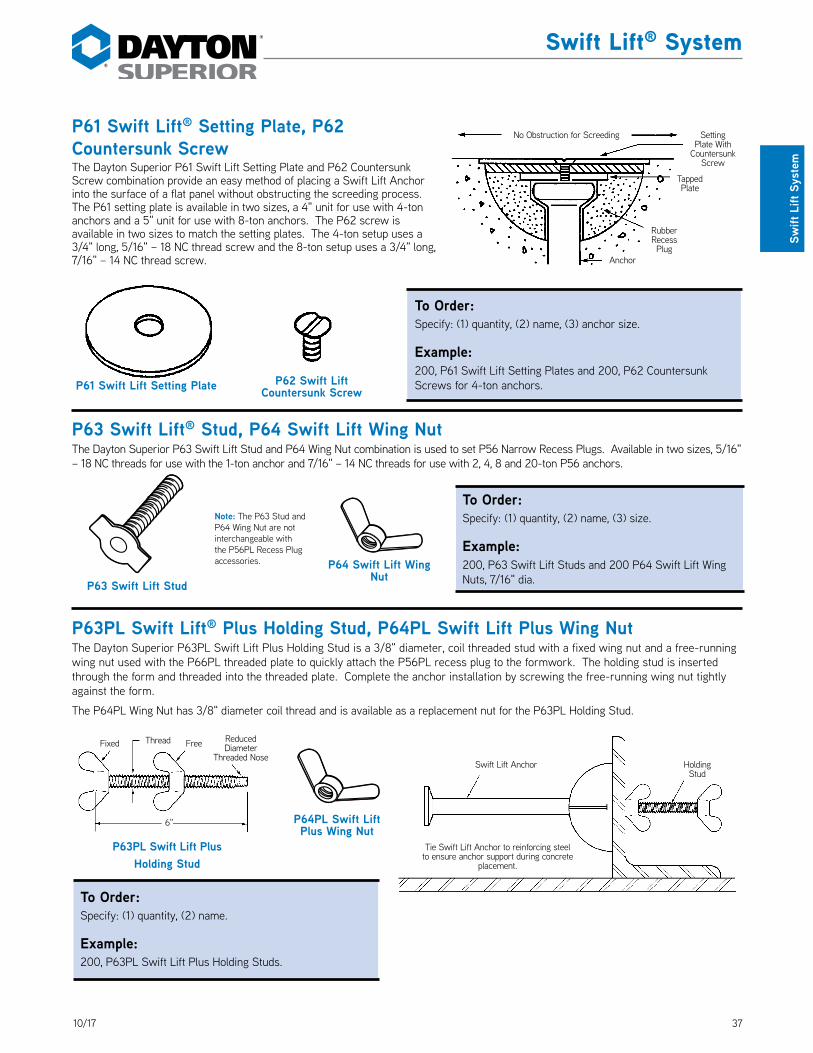
3710/17
Swift Lift® System
Swift
Lift
Sys
tem
P61 Swift Lift® Setting Plate, P62 Countersunk ScrewThe Dayton Superior P61 Swift Lift Setting Plate and P62 Countersunk Screw combination provide an easy method of placing a Swift Lift Anchor into the surface of a flat panel without obstructing the screeding process. The P61 setting plate is available in two sizes, a 4" unit for use with 4-ton anchors and a 5" unit for use with 8-ton anchors. The P62 screw is available in two sizes to match the setting plates. The 4-ton setup uses a 3/4" long, 5/16" – 18 NC thread screw and the 8-ton setup uses a 3/4" long, 7/16" – 14 NC thread screw. DS_P61_P62
P61 Swift Lift Setting Plate P62 Swift Lift Countersunk Screw
No Obstruction for Screeding Setting Plate With
Countersunk Screw
Tapped Plate
Rubber Recess Plug
Anchor
P63 Swift Lift® Stud, P64 Swift Lift Wing NutThe Dayton Superior P63 Swift Lift Stud and P64 Wing Nut combination is used to set P56 Narrow Recess Plugs. Available in two sizes, 5/16" – 18 NC threads for use with the 1-ton anchor and 7/16" – 14 NC threads for use with 2, 4, 8 and 20-ton P56 anchors. DS_P63_P64
P64 Swift Lift Wing Nut
P63 Swift Lift Stud
Note: The P63 Stud and P64 Wing Nut are not interchangeable with the P56PL Recess Plug accessories.
P63PL Swift Lift PlusHolding Stud
6"
Fixed FreeThread Reduced Diameter
Threaded Nose
P63PL Swift Lift® Plus Holding Stud, P64PL Swift Lift Plus Wing NutThe Dayton Superior P63PL Swift Lift Plus Holding Stud is a 3/8" diameter, coil threaded stud with a fixed wing nut and a free-running wing nut used with the P66PL threaded plate to quickly attach the P56PL recess plug to the formwork. The holding stud is inserted through the form and threaded into the threaded plate. Complete the anchor installation by screwing the free-running wing nut tightly against the form. DS_P63PL_P64PL
The P64PL Wing Nut has 3/8" diameter coil thread and is available as a replacement nut for the P63PL Holding Stud.
P64PL Swift Lift Plus Wing Nut
Tie Swift Lift Anchor to reinforcing steel to ensure anchor support during concrete
placement.
Swift Lift Anchor Holding Stud
To Order:Specify: (1) quantity, (2) name, (3) anchor size.
Example:200, P61 Swift Lift Setting Plates and 200, P62 Countersunk Screws for 4-ton anchors.
To Order:Specify: (1) quantity, (2) name, (3) size.
Example:200, P63 Swift Lift Studs and 200 P64 Swift Lift Wing Nuts, 7/16" dia.
To Order:Specify: (1) quantity, (2) name.
Example:200, P63PL Swift Lift Plus Holding Studs.

38 10/17
Swift Lift® System
Swift Lift System
P66 Swift Lift® Tapped PlateThe Dayton Superior Swift Lift Tapped Plate (P66) is tapped for either a 5/16" or 7/16" diameter NC thread and used to install the P56 Narrow Recess Plug. This is a replacement plate only; it can be used with the P63 Stud or with NC bolts supplied by others. DS_P66
P66PL Swift Lift® Plus Threaded PlateP67PL Swift Lift® Plus Stud PlateP68PL Swift Lift® Plus Holding PlateThe Dayton Superior P66PL Swift Lift Plus Threaded Plate, P67PL Stud Plate and P68PL Holding Plate are working parts used to install the P56PL Recess Plug in various applications. These working parts are available in 1, 2, 4 and 8-ton system sizes. DS_P66PL_P67PL_P68PL
P69 Swift Lift® Magnetic Setting PlateThe Dayton Superior P69 Swift Lift Magnetic Setting Plates are available to firmly set P56PL Recess Plugs in metal, precast concrete forms. The reusable magnetic setting plate eliminates holes drilled in the metal forms for anchor setting purposes. DS_P69
P104S Magnetic One Piece Swift Lift® RecessThe Dayton Superior P104S Magnetic OnePiece Swift Lift Recess is a urethane recess plug with magnets embedded in the face for easy attachment to metal forms. This provides the precaster the option for a one-piece unit versus P56PL Swift Lift Recess Plug and P69 Magnetic Setting Plate. It is available in 2, 4 and 8-ton sizes. DS_P104
P66PL Swift Lift Plus Threaded Plate
P68PL Swift Lift Plus Holding Plate
P67PL Swift Lift Plus Stud Plate
Length
P69 Swift Lift Magnetic Setting Plate
5/16" or 7/16" Dia. NC Threads
P66 Swift Lift Tapped Plate
NOTE: One piece recess plug with magnets imbedded in top available, contact DSC Customer Service.
Diameter
“Z”
To Order:Specify: (1) quantity, (2) name, (3) thread size.
Example:100, P66 Swift Lift Tapped Plate, 7/16" dia. NC thread.
To Order:Specify: (1) quantity, (2) name, (3) system size.
Example:100, P66PL Swift Lift Plus Threaded Plate, 4-ton system.
To Order:Specify: (1) quantity, (2) name, (3) system size.
Example:20, P69 Swift Lift Magnetic Setting Plates, 4-ton system.
To Order:Specify: (1) quantity, (2) name, (3) system size.
Example:20, P104 Magnetic OnePiece Swift Lift Magnetic Recess, 8-ton system.
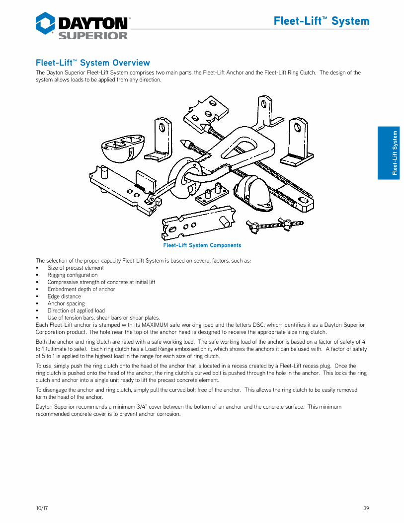
3910/17
Fleet-Lift™ System
Flee
t-Li
ft Sy
stem
Fleet-Lift™ System OverviewThe Dayton Superior Fleet-Lift System comprises two main parts, the Fleet-Lift Anchor and the Fleet-Lift Ring Clutch. The design of the system allows loads to be applied from any direction.
The selection of the proper capacity Fleet-Lift System is based on several factors, such as:• Size of precast element• Rigging configuration• Compressive strength of concrete at initial lift• Embedment depth of anchor• Edge distance• Anchor spacing• Direction of applied load• Use of tension bars, shear bars or shear plates.Each Fleet-Lift anchor is stamped with its MAXIMUM safe working load and the letters DSC, which identifies it as a Dayton Superior Corporation product. The hole near the top of the anchor head is designed to receive the appropriate size ring clutch.
Both the anchor and ring clutch are rated with a safe working load. The safe working load of the anchor is based on a factor of safety of 4 to 1 (ultimate to safe). Each ring clutch has a Load Range embossed on it, which shows the anchors it can be used with. A factor of safety of 5 to 1 is applied to the highest load in the range for each size of ring clutch.
To use, simply push the ring clutch onto the head of the anchor that is located in a recess created by a Fleet-Lift recess plug. Once the ring clutch is pushed onto the head of the anchor, the ring clutch’s curved bolt is pushed through the hole in the anchor. This locks the ring clutch and anchor into a single unit ready to lift the precast concrete element.
To disengage the anchor and ring clutch, simply pull the curved bolt free of the anchor. This allows the ring clutch to be easily removed form the head of the anchor.
Dayton Superior recommends a minimum 3/4" cover between the bottom of an anchor and the concrete surface. This minimum recommended concrete cover is to prevent anchor corrosion.
Fleet-Lift System Components

40 10/17
Fleet-Lift™ System
Fleet-Lift System
P91S Fleet-Lift Ring ClutchThe P91S Fleet-Lift Ring Clutch consists of a clutch body, a curved bolt and a high strength bail. Installation and release is safe and simple. After the clutch is inserted over the anchor head and into the recess, the curved bolt is rotated into the closed position. DS_P91S
Rotation of the standard bail is a full 360°. Once engaged and supporting four hundred pounds of load, the ring clutch cannot be released.
Installation of P91S Ring Clutch
A
B
G
F
D
E
C
P91S Fleet-Lift Ring Clutch
The P91S Ring Clutch is located directly over the head of a Fleet-Lift Anchor.
The ring clutch is pushed down onto the anchor head and the curved bolt is rotated through the engagement hole of the anchor and locked into position. The process of engaging anchor and ring clutch is completed in seconds.
P91S Fleet-Lift Ring Clutch Selection TableSafe Working
Load (Tons)
Load Range (Tons)
Product Code A B C D E F G
3 2-3 FL001S 3-3/4" 2-3/8" 10-1/2" 3" 7" 3" 1"
6 4-6 FL002S 4-3/4" 2-5/8" 12-1/2" 4" 8-1/4" 3-1/2" 1-1/2"
12 8-12 FL003S 5-7/8" 3" 17-3/4" 5-7/8" 11" 4-1/2" 2-1/8"
Safe Working Load provides a factor of safety of approximately 5 to 1.
To Order:Specify: (1) quantity, (2) name, (3) product code, (4) system size.
Example:9, P91S Fleet-Lift Ring Clutches, FL002S, 4/6-ton units.
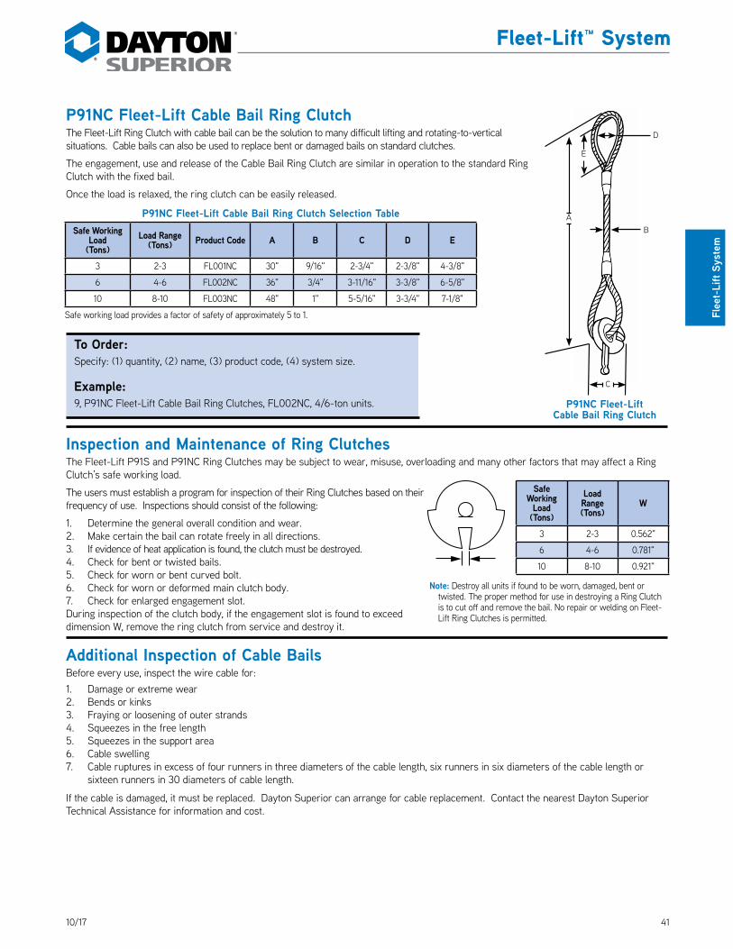
4110/17
Fleet-Lift™ System
Flee
t-Li
ft Sy
stem
P91NC Fleet-Lift Cable Bail Ring ClutchThe Fleet-Lift Ring Clutch with cable bail can be the solution to many difficult lifting and rotating-to-vertical situations. Cable bails can also be used to replace bent or damaged bails on standard clutches.
The engagement, use and release of the Cable Bail Ring Clutch are similar in operation to the standard Ring Clutch with the fixed bail. DS_P91NC
Once the load is relaxed, the ring clutch can be easily released.
Inspection and Maintenance of Ring ClutchesThe Fleet-Lift P91S and P91NC Ring Clutches may be subject to wear, misuse, overloading and many other factors that may affect a Ring Clutch’s safe working load.
The users must establish a program for inspection of their Ring Clutches based on their frequency of use. Inspections should consist of the following:
1. Determine the general overall condition and wear.2. Make certain the bail can rotate freely in all directions.3. If evidence of heat application is found, the clutch must be destroyed.4. Check for bent or twisted bails.5. Check for worn or bent curved bolt.6. Check for worn or deformed main clutch body.7. Check for enlarged engagement slot.During inspection of the clutch body, if the engagement slot is found to exceed dimension W, remove the ring clutch from service and destroy it.
Additional Inspection of Cable BailsBefore every use, inspect the wire cable for:1. Damage or extreme wear2. Bends or kinks3. Fraying or loosening of outer strands4. Squeezes in the free length5. Squeezes in the support area6. Cable swelling7. Cable ruptures in excess of four runners in three diameters of the cable length, six runners in six diameters of the cable length or
sixteen runners in 30 diameters of cable length.
If the cable is damaged, it must be replaced. Dayton Superior can arrange for cable replacement. Contact the nearest Dayton Superior Technical Assistance for information and cost.
P91NC Fleet-Lift Cable Bail Ring Clutch Selection TableSafe Working
Load (Tons)
Load Range (Tons) Product Code A B C D E
3 2-3 FL001NC 30" 9/16" 2-3/4" 2-3/8" 4-3/8"
6 4-6 FL002NC 36" 3/4" 3-11/16" 3-3/8" 6-5/8"
10 8-10 FL003NC 48" 1" 5-5/16" 3-3/4" 7-1/8"
Safe working load provides a factor of safety of approximately 5 to 1.
P91NC Fleet-Lift Cable Bail Ring Clutch
BA
C
E
D
To Order: Specify: (1) quantity, (2) name, (3) product code, (4) system size.
Example:9, P91NC Fleet-Lift Cable Bail Ring Clutches, FL002NC, 4/6-ton units.
Note: Destroy all units if found to be worn, damaged, bent or twisted. The proper method for use in destroying a Ring Clutch is to cut off and remove the bail. No repair or welding on Fleet-Lift Ring Clutches is permitted.
Safe Working
Load (Tons)
Load Range (Tons)
W
3 2-3 0.562"
6 4-6 0.781"
10 8-10 0.921"
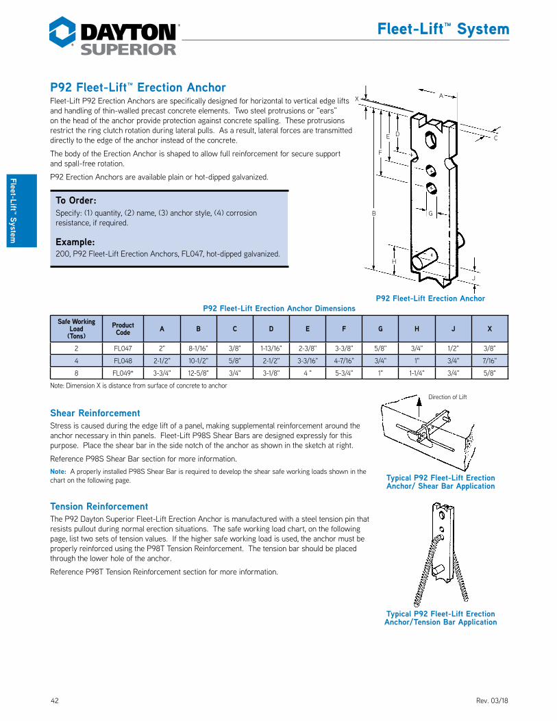
42 10/17
Fleet-Lift™ System
Fleet-Lift™ System
P92 Fleet-Lift™ Erection AnchorFleet-Lift P92 Erection Anchors are specifically designed for horizontal to vertical edge lifts and handling of thin-walled precast concrete elements. Two steel protrusions or “ears” on the head of the anchor provide protection against concrete spalling. These protrusions restrict the ring clutch rotation during lateral pulls. As a result, lateral forces are transmitted directly to the edge of the anchor instead of the concrete. DS_P92
The body of the Erection Anchor is shaped to allow full reinforcement for secure support and spall-free rotation.
P92 Erection Anchors are available plain or hot-dipped galvanized.
P92 Fleet-Lift Erection Anchor DimensionsSafe Working
Load(Tons)
Product Code A B C D E F G H J X
2 FL047 2" 8-1/16" 3/8" 1-13/16" 2-3/8" 3-3/8" 5/8" 3/4" 1/2" 3/8"
4 FL048 2-1/2" 10-1/2" 5/8" 2-1/2" 3-3/16" 4-7/16" 3/4" 1" 3/4" 7/16"
8 FL049* 3-3/4" 12-5/8" 3/4" 3-1/8" 4 " 5-3/4" 1" 1-1/4" 3/4" 5/8"
Note: Dimension X is distance from surface of concrete to anchor
Shear ReinforcementStress is caused during the edge lift of a panel, making supplemental reinforcement around the anchor necessary in thin panels. Fleet-Lift P98S Shear Bars are designed expressly for this purpose. Place the shear bar in the side notch of the anchor as shown in the sketch at right.
Reference P98S Shear Bar section for more information.Note: A properly installed P98S Shear Bar is required to develop the shear safe working loads shown in the chart on the following page.
Tension ReinforcementThe P92 Dayton Superior Fleet-Lift Erection Anchor is manufactured with a steel tension pin that resists pullout during normal erection situations. The safe working load chart, on the following page, list two sets of tension values. If the higher safe working load is used, the anchor must be properly reinforced using the P98T Tension Reinforcement. The tension bar should be placed through the lower hole of the anchor.
Reference P98T Tension Reinforcement section for more information.
Typical P92 Fleet-Lift Erection Anchor/Tension Bar Application
Typical P92 Fleet-Lift Erection Anchor/ Shear Bar Application
Direction of Lift
P92 Fleet-Lift Erection Anchor
A
DE
F
B G
J
C
H
X
To Order:Specify: (1) quantity, (2) name, (3) anchor style, (4) corrosion resistance, if required.
Example:200, P92 Fleet-Lift Erection Anchors, FL047, hot-dipped galvanized.
Rev. 03/18

4310/17
Fleet-Lift™ System
Flee
t-Li
ft Sy
stem
P92 Fleet-Lift Erection Anchor Tension and Shear CapacitiesP92 Fleet-Lift Erection Anchor
(ton x length) Product Code Precast Concrete Panel Thickness
Shear Safe Working Load with Shear Bar
Tension Safe Working Load with Anchor Only
Tension Safe Working Load With Tension Bar
2-ton x 8" long FL047 4" Min. 1,650 lbs. 2,575 lbs. 4,000 lbs.
5" 1,875 lbs. 3,350 lbs.
6" 2,125 lbs. 3,850 lbs.
7" 2,400 lbs. 4,000 lbs.
8" 2,700 lbs. 4,000 lbs.
9" 2,925 lbs. 4,000 lbs.
10" 3,275 lbs. 4,000 lbs.
11" 3,575 lbs. 4,000 lbs.
12" 4,000 lbs. 4,000 lbs.
4-ton x 10-7/16" long FL048 5-1/2" Min. 2,400 lbs. 4,700 lbs. 8,000 lbs.
6" 3,075 lbs. 5,050 lbs.
7" 3,250 lbs. 5,825 lbs.
8" 3,425 lbs. 6,600 lbs.
9" 3,825 lbs. 7,350 lbs.
10" 4,250 lbs. 8,000 lbs.
11" 4,650 lbs. 8,000 lbs.
12" 5,050 lbs. 8,000 lbs.
8-ton x 13-1/4" long FL049 7-1/2" Min. 4,000 lbs. 7,500 lbs. 16,000 lbs.
8" 4,200 lbs. 7,775 lbs.
9" 4,550 lbs. 8,300 lbs.
10" 4,950 lbs. 8,800 lbs.
11" 5,050 lbs. 10,000 lbs.
12" 5,175 lbs. 11,300 lbs.Notes:1. Safe Working Loads are based on approximately a 4 to 1 factor of safety in 3,500 psi normal weight concrete.2. Install shear bar and tension bar, when required, per instructions on preceding page.

44 10/17
Fleet-Lift™ System
Fleet-Lift System
P92P Fleet-Lift Erection Anchor with Shear PlateThe P92P Fleet-Lift Erection Anchor with Shear Plate is designed specifically for edge tilting precast concrete elements from the horizontal to a vertical position. An integral shear plate eliminates any possibility of forgetting to install a required shear bar. DS_P92P
As on other Fleet-Lift Erection Anchors, two steel protrusions or “ears” at the head of the anchor provide protection against concrete spalling. These “ears” restrict the ring clutch rotation during lateral pulls. As a result, lateral forces are transmitted directly to the edge of the anchor instead of the concrete.
The body of the erection anchor is shaped to allow full reinforcement for secure support and spall-free rotation.
P92P Erection Anchors are available plain or hot-dipped galvanized.
Safe WorkingLoad
(Tons)Product Code A B C D
2 FL147 2-1/2" 3/4" 3" 1/4"
4 FL148 2-1/2" 1-1/4" 3" 3/8"
8 FL149* 3" 1-5/8" 3-1/2" 3/8"
Anchor dimensions not shown are the same as the P92 Erection Anchor of the same load range.
Shear ReinforcementStress is caused during the edge lifting of a precast panel, making supplemental reinforcement around the anchor necessary in thin panels. The Fleet-Lift P92P Erection Anchor with integral Shear Plate is designed expressly for this purpose. Install the anchor so that the shear plate is opposite the direction of lift.
Tension ReinforcementThe P92P with Shear Plate Fleet-Lift Erection Anchor is manufactured with a steel tension pin that resists pullout during normal erection situations. The safe working load chart on the following page lists two sets of tension values. If the higher safe working load is used, the anchor must be properly reinforced using the P98T Tension Bar. The tension bar should be placed through the lower hole.
P92P Fleet-Lift Erection Anchor with Shear Plate
A
B
C
D
Typical P92P Fleet-Lift Erection Anchor Shear
Plate/Tension Bar Application
Typical P92P Fleet-Lift
Erection Anchor with Shea Plate
Application
Direction of Lift
To Order:Specify: (1) quantity, (2) name, (3) product code, (4) corrosion resistance, if required.
Example:200, P92P Fleet-Lift Erection Anchor with Shear Plate, FL148, hot-dipped galvanized.
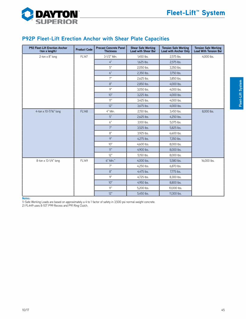
4510/17
Fleet-Lift™ System
Flee
t-Li
ft Sy
stem
P92P Fleet-Lift Erection Anchor with Shear Plate CapacitiesP92 Fleet-Lift Erection Anchor
(ton x length) Product Code Precast Concrete Panel Thickness
Shear Safe Working Load with Shear Bar
Tension Safe Working Load with Anchor Only
Tension Safe Working Load With Tension Bar
2-ton x 8" long FL147 3-1/2" Min. 1,450 lbs. 2,575 lbs. 4,000 lbs.
4" 1,625 lbs. 2,575 lbs.
5" 2,050 lbs. 3,350 lbs.
6" 2,350 lbs. 3,750 lbs.
7" 2,625 lbs. 3,850 lbs.
8" 2,850 lbs. 4,000 lbs.
9" 3,050 lbs. 4,000 lbs.
10" 3,225 lbs. 4,000 lbs.
11" 3,425 lbs. 4,000 lbs.
12" 3,675 lbs. 4,000 lbs.
4-ton x 10-7/16" long FL148 4" Min. 2,150 lbs. 3,450 lbs. 8,000 lbs.
5" 2,625 lbs. 4,250 lbs.
6" 3,100 lbs. 5,075 lbs.
7" 3,525 lbs. 5,825 lbs.
8" 3,925 lbs. 6,600 lbs.
9" 4,275 lbs. 7,350 lbs.
10" 4,600 lbs. 8,000 lbs.
11" 4,900 lbs. 8,000 lbs.
12" 5,150 lbs. 8,000 lbs.
8-ton x 13-1/4" long FL149 6" Min." 4,000 lbs. 5,580 lbs. 16,000 lbs.
7" 4,250 lbs. 6,870 lbs.
8" 4,475 lbs. 7,775 lbs.
9" 4,725 lbs. 8,300 lbs.
10" 4,950 lbs. 8,800 lbs.
11" 5,200 lbs. 10,000 lbs.
12" 5,450 lbs. 11,300 lbs.Notes:1) Safe Working Loads are based on approximately a 4 to 1 factor of safety in 3,500 psi normal weight concrete.2) FL449 uses 8-10T P99 Recess and P91 Ring Clutch.

46 10/17
Fleet-Lift™ System
Fleet-Lift System
P92DP Fleet-Lift Erection Anchor with Shear Plate and Shear PinThe Dayton Superior P92DP Fleet-Lift Erection Anchor with a Shear Plate and a Shear Pin is similar to the P92P anchor with the addition of a shear pin. By welding a solid shear pin opposite the shear plate, the anchor can resist shear loads in both directions. DS_P92DP
Installation and Primary Shear LoadingThe P92DP anchor is set in the form with the shear plate in the down position to resist the primary shear load.
Secondary Shear LoadingWhen the panel is placed on an “A” frame is required to be rotated 180˚, the addition of the shear pin works with the shear plate to resist the shear load in the opposite direction of the shear plate. The shear pin helps to protect the concrete from spalling when the shear loads are applied in a secondary direction.
P92DP Erection Anchors are available either plain or hot-dipped galvanized steel.
Safe Working Load
(Tons)Product Code A B C D E F
2 FL647 2-1/2" 3/4" 3" 1/4" 1/2" 2-3/4"
4 FL648 2-1/2" 1-1/4" 3" 3/8" 3/4" 2-7/8"
8 FL649 3" 1-5/8" 3-1/2" 3/8" 3/4" 2-7/8"
Anchor dimensions not shown are the same as the P92 Erection Anchor of the same load range.
Tension ReinforcementThe P92DP Fleet-Lift Erection Anchor is manufactured with a steel tension pin that resists pullout during normal erection situations. The safe working load chart on the following page lists two sets of tension values. If the higher safe working load is used, the anchor must be properly reinforced using the P98T Tension Bar. The tension bar should be placed through the lower hole of the anchor.
P92DP Fleet-Lift Erection Anchor with Shear Plate/Pin
A
E
F
B
C
D
Shear Plate
Solid Shear Pin
Direction of Lift for Primary Shear
Direction of Lift for Secondary Shear
To Order:Specify: (1) quantity, (2) name, (3) product code, (4) corrosion resistance, if required.
Example:200, P92DP Fleet-Lift Erection Anchor with Shear Plate/Pin, FL744, 4/6-ton system size, hot-dipped galvanized.

4710/17
Fleet-Lift™ System
Flee
t-Li
ft Sy
stem
P92DP Fleet-Lift Erection Anchor with Shear Plate and Shear Pin Capacities
P92DP Fleet-Lift Erection Anchor(ton x length)
Product Code
Precast Concrete Panel Thickness
Shear Safe Working Load with Shear
Bar
Shear Safe Working Load for Secondary
Shear
Tension Safe Working Load with
Anchor Only
Tension Safe Working Load With
Tension Bar2-ton x 8" long FL647 3-1/2" Min. 1,450 lbs. 1,150 lbs. 2,575 lbs. 4,000 lbs.
4" 1,625 lbs. 1,300 lbs. 2,575 lbs.
5" 2,050 lbs. 1,650 lbs. 3,350 lbs.
6" 2,350 lbs. 1,750 lbs. 3,750 lbs.
7" 2,625 lbs. 1,875 lbs. 3,850 lbs.
8" 2,850 lbs. 2,100 lbs. 4,000 lbs.
9" 3,050 lbs. 2,275 lbs. 4,000 lbs.
10" 3,225 lbs. 2,450 lbs. 4,000 lbs.
11" 3,425 lbs. 2,575 lbs. 4,000 lbs.
12" 3,675 lbs. 2,950 lbs. 4,000 lbs.
4-ton x 10-7/16" long FL648 4" Min. 2,150 lbs. 1,725 lbs. 3,450 lbs. 8,000 lbs.
5" 2,625 lbs. 2,100 lbs. 4,250 lbs.
6" 3,100 lbs. 2,475 lbs. 5,075 lbs.
7" 3,525 lbs. 2,825 lbs. 5,825 lbs.
8" 3,925 lbs. 3,150 lbs. 6,600 lbs.
9" 4,275 lbs. 3,425 lbs. 7,350 lbs.
10" 4,600 lbs. 3,675 lbs. 8,000 lbs.
11" 4,900 lbs. 3,925 lbs. 8,000 lbs.
12" 5,150 lbs. 4,125 lbs. 8,000 lbs.
8-ton x 13-1/4" long FL649 6" Min." 4,000 lbs. 3,200 lbs. 5,580 lbs. 16,000 lbs.
7" 4,250 lbs. 3,400 lbs. 6,870 lbs.
8" 4,475 lbs. 3,575 lbs. 7,775 lbs.
9" 4,725 lbs. 3,775 lbs. 8,300 lbs.
10" 4,950 lbs. 3,975 lbs. 8,800 lbs.
11" 5,200 lbs. 4,150 lbs. 10,000 lbs.
12" 5,450 lbs. 4,350 lbs. 11,300 lbs.Notes:1) Safe Working Load is based on an approximate factor of safety of 4 to 1 in 3,500 psi normal weight concrete.2) Install anchors as shown on preceding page to develop safe working loads in chart.

48 10/17
Fleet-Lift™ System
Fleet-Lift™ System
P92FE Fleet‑Lift™ Forged Erection AnchorThe Dayton Superior P92FE Forged Erection Anchor is specifically designed to provide greater lifting capacities for horizontal to vertical edge lifts. The anchors are forged to provide 20% greater safe working loads. The head of the anchor is designed with two protrusions or "ears" on the head of the anchor which provide protection against concrete spalling. These protrusions restrict the ring clutch rotation during lateral pulls. As a result, lateral forces are transmitted directly to the edge of the anchor instead of the concrete. DS_P92FE
The P92FE Forged Erection Anchor utilizes the Fleet P91S or Fleet P91NC lifting hardware and the P99 Recess Plugs. P92FE Forged Erection Anchors are available in plain or hot-dipped galvanized finishes.
P92FE Capacity Product Code (Galvanized)
3-Ton 127518
6-Ton 143421
10-Ton 143423
To Order:Specify: (1) quantity, (2) name, (3) product code, (4) finish.
Example:200, P92FE Fleet-Lift Forged Erection Anchors, #126748, hot-dipped galvanized.
P92FE Forged Erection Anchor
Ton x Length Slab Thickness Insert Height Minimum Edge Distance
Minimum Corner Distance
Shear Safe Working Load with Shear Bar
Tension Safe Working Load Anchor Only
Tension Safe Working Load
with Tension Bar
3-ton x 8"
4" Min.
8"
2"
12"
1,390 lbs. 2,500 lbs.
6,000 lbs.
5" 2-1/2" 1,680 lbs. 3,130 lbs.
6" 3" 1,980 lbs. 3,760 lbs.
7" 3-1/2" 2,300 lbs. 4,380 lbs.
8" 4" 2,630 lbs. 5,010 lbs.
9" 4-1/2" 2,980 lbs. 5,640 lbs.
10" 5" 3,340 lbs. 6,000 lbs.
11" 5-1/2" 3,720 lbs. 6,000 lbs.
12" 6" 4,110 lbs. 6,000 lbs.
6-ton x 10-3/8"
5-1/2" Min.
10-3/8"
2-3/4"
16"
2,840 lbs. 4,720 lbs.
12,000 lbs.
6" 3" 3,030 lbs. 5,150 lbs.
7" 3-1/2" 3,430 lbs. 6,010 lbs.
8" 4" 3,840 lbs. 6,870 lbs.
9" 4-1/2" 4,270 lbs. 7,730 lbs.
10" 5" 4,710 lbs. 8,590 lbs.
11" 5-1/2" 5,010 lbs. 9,450 lbs.
12" 6" 5,540 lbs. 10,310 lbs.
10-ton x 12-3/4"
7 1/2"
12-3/4"
3-3/4"
19"
4,180 lbs. 7,920 lbs.
20,000 lbs.
8" 4" 4,420 lbs. 8,440 lbs.
9" 4-1/2" 4,920 lbs. 9,500 lbs.
10" 5" 5,430 lbs. 10,560 lbs.
11" 5-1/2" 5,950 lbs. 11,610 lbs.
12" 6" 6,490 lbs. 12,670 lbs.
Safe Working Load provides a factor of safety approximately 4 to 1 in 3,500 psi normal weight concrete.
Rev. 02/18

4910/17
Fleet-Lift™ System
Flee
t-Li
ft™ S
yste
m
P92FEW Fleet‑Lift™ Forged Erection Anchor with Sheer PlateThe P92FEW Forged Erection Anchor with Shear Plate eliminates the need for a shear bar. The P92FE and P92FEW anchors are stocked in plain and galvanized finishes. DS_P92FEW
P92FEW Capacity
Product Code (Plain)
Product Code (Galvanized)
3 Ton 129473 139577
6 Ton 143424 143425
10 Ton 143426 143427
12 Ton 100148 100149
To Order:Specify: (1) quantity, (2) name, (3) product code, (4) finish.
Example:200, P92FEW Fleet-Lift Forged Erection Anchors, #139577, hot-dipped galvanized.
P92FEW Fleet Forged Erection Anchor
Ton x Length Slab Thickness Minimum Edge Distance
Minimum Corner Distance
Shear Safe Working Load with Shear Plate
Tension Safe Working Load Anchor Only
Tension Safe Working Load w/ Tension Bar
3 Ton x 8"
4" 2"
12"
1,800 lbs
6,000 lbs 6,000 lbs
5" 2-1/2" 2,300 lbs
6" 3" 2,800 lbs
7" 3-1/2" 3,400 lbs
8" 4" 4,000 lbs
9" 4-1/2" 4,400 lbs
10" 5" 4,800 lbs
11" 5-1/2" 5,200 lbs
12" 6" 5,700 lbs
6 Ton x 10-3/8"
5-1/2" 2-3/4"
16"
3,100 lbs 10,000 lbs
12,000 lbs
6" 3" 3,250 lbs 10,500 lbs
7" 3-1/2" 3,700 lbs 11,500 lbs
8" 4" 4,040 lbs 12,000 lbs
9" 4-1/2" 4,600 lbs 12,000 lbs
10" 5" 5,000 lbs 12,000 lbs
11" 5-1/2" 5,500 lbs 12,000 lbs
12" 6" 6,100 lbs 12,000 lbs
10 Ton x 12-3/4"
7-1/2" 3-3/4"
19"
4,600 lbs 17,890 lbs
20,000 lbs
8" 4" 4,800 lbs 18,825 lbs
9" 4-1/2" 5,450 lbs 19,760 lbs
10" 5" 6,100 lbs 20,000 lbs
11" 5-1/2" 6,800 lbs 20,000 lbs
12" 6" 7,600 lbs 20,000 lbs
12 Ton x 12-3/4"
7-1/2" 3-3/4"
19"
4,600 lbs 17,890 lbs
23,450 lbs
8" 4" 4,800 lbs 18,825 lbs
9" 4-1/2" 5,450 lbs 19,760 lbs
10" 5" 6,100 lbs 20,695 lbs
11" 5-1/2" 6,800 lbs 21,630 lbs
12" 6" 7,600 lbs 22,565 lbs
Safe Working Load provides a factor of safety approximately 4 to 1 in 3,500 psi normal weight concrete.Anchors were tested in concrete with minimum reinforcing per ACI 318
Rev. 02/18

50 10/17
Fleet-Lift™ System
Fleet-Lift™ System
P92FEWDP Forged Erection Anchor with Shear Plate and Secondary Shear PinThe P92FEWDP Forged Erection Anchor with Shear Plate is specifically designed to provide greater lifting capacities for horizontal to vertical edge lifts. By welding a solid shear pin opposite the shear plate, the anchor can resist shear loads in both directions. The anchors are forged to provide 20% greater safe working loads. The P92FEWDP eliminates the need for a shear bar on the primary and secondary shear loading. DS_P92FEWDP
Due to the anchor being forged, it does not depend on welds or thread engagement to develop its safe working load. Forging provides maximum safety with its advantageous material structure. This allows the anchor to easily meet the OSHA requirement of 4 to 1 factor of safety.
PRODUCT APPLICATION:The P92FEWDP Forged Erection Anchor with Shear Plate and Secondary Shear Pin is designed specifically for edge tilting precast concrete elements from the horizontal to vertical position. When the panel is placed on an “A” frame or is required to be rotated 180°, the addition of the shear pin works with the shear plate to resist the shear load in the opposite direction of the shear plate. The shear pin helps to protect the concrete from spalling when the shear loads are applied in a secondary direction.
PRODUCT FEATURES AND BENEFITS:The P92FEWDP has two steel protrusions or “ears” at the head of the anchor which provides protection against concrete spalling. These “ears” restrict the ring clutch rotation during lateral pulls. As a result, lateral forces are transmitted directly to the edge of the anchor instead of the concrete.
The P92FEWDP Forged Erection Anchor utilizes the Fleet P91S or Fleet P91NC lifting hardware and the P99 Recess Plugs.
The P92FEWDP Forged erection Anchors are available in a plain finish.
INSTALLATION:The P92FEWDP anchor is set in the form with the shear plate in the down position to resist the primary shear load.
P92FEWDP Forged Erection Anchor(Ton x Length)
Product Code Slab Thickness Shear Safe Working Load Primary Shear
Shear Safe Working Load Secondary
Shear
Tension Safe Working Load Anchor Only
Tension Safe Working Load with
Tension Bar
3 Ton x 8" 142881
4" 1,800 lbs 1,390 lbs
6,000 lbs 6,000 lbs8" 4,000 lbs 3,000 lbs
12" 5,700 lbs 4,425 lbs
6 Ton x 10-3/8" 142882
5-1/2" 3,100 lbs 2,560 lbs 10,000 lbs
12,000 lbs8" 4,040 lbs 3,660 lbs 12,000 lbs
12" 6,100 lbs 5,600 lbs 12,000 lbs
10 Ton x 12-3/4" 142883
7-1/2" 4,600 lbs 3,630 lbs 17,890 lbs
20,000 lbs10" 6,100 lbs 4,900 lbs 20,000 lbs
12" 7,600 lbs 6,520 lbs 20,000 lbs
12 Ton x 12-3/4" 100155
7-1/2" 4,600 lbs 3,630 lbs 17,890 lbs
23,450 lbs10" 6,100 lbs 4,900 lbs 20,695 lbs
12" 7,600 lbs 6,520 lbs 22,565 lbs
Safe working load provides a factor of safety approximately 4 to 1 in 3.500 psi normal weight concreteAnchors were tested in concrete with minimum reinforcing per ACI 318
To Order:Specify: (1) quantity, (2) name, (3) product code, (4) finish.
Example:200, P92FEWDP 3-Ton 8" Fleet-Lift Forged Erection Anchor with Shear Plate and Secondary Shear Pin, 142881, plain finish.
P92FEWDP Product Code (Plain)
Product Code (Galvanized)
3 Ton 142881 MTO
6 Ton 142882 MTO
10 Ton 142883 MTO
12 Ton 100155 MTO
Rev. 02/18

5110/17
Fleet-Lift™ System
Flee
t-Li
ft Sy
stem
P92H Fleet-Lift Two-Hole Erection AnchorP92HP Fleet-Lift Two-Hole Erection Anchor with Shear PlateFleet-Lift Two-Hole Erection Anchors combine the strength, spall resistance and high tension performance of the P92 Erection Anchor.
The P92H Two-Hole Erection Anchor was designed for use where the lift direction applies a tension load ONLY to the anchor. A properly installed P98T Tension Bar is always required when using this erection anchor. For shear applications the P98S Shear Bar is designed to fit over the P92H. The design of the shear bar allows it to fit over the top edge of the anchor. It is placed in the top notch and secured so that it bears tightly against the bottom of the notch. Accurate placement of the shear bar provides for spall-free edge lifting. DS_P92H
The P92HP Two-Hole Erection Anchor was designed for use where the lift direction applies both a shear and tension load to the anchor. As with the P92H anchor, a properly installed P98T Tension Bar is always required when using the P92HP Erection Anchor. Shear loading for this anchor is resisted by the P92HP anchor’s integral shear plate. DS_P92HP
Both the P92H and P92HP Erection Anchors are available in 2, 4, 6 or 8-ton capacities. In addition, they are available in either plain or hot-dipped galvanized finish.
P92H Fleet-Lift Two-Hole Erection Anchor(ton x length)
Product Code A B C
P92HP Fleet-Lift Two-Hole Erection Anchor with Shear plate
(ton x length)Product Code D E F
2-ton x 4-1/4" long FL403 2" 4-1/4" 3/8" 2-ton x 4-1/4" long FL423 2-1/2" 3" 1/4"
2-ton x 8-1/4" long FL903 2" 8-1/4" 3/8" 2-ton x 8-1/4" long FL403L 2-1/2" 3" 1/4"
4-ton x 7-7/8" long FL075 2-1/2" 7-7/8" 5/8" 4-ton x 7-7/8" long FL275 2-1/2" 3" 3/8"
4-ton x 10-7/8" long FL975 2-1/2" 10-7/8" 5/8" 4-ton x 10-7/8" long FL175L 2-1/2" 3" 3/8"
8-ton x 13-1/4" long FL185L 3-3/4" 13-1/4" 3/4" 8-ton x 13-1/4" long FL285L 3" 3-1/2" 3/8"
Anchor dimensions not shown are the same as the P92 Erection Anchor of the same load range.
Shear ReinforcementStress is caused during the edge lifting of a precast concrete panel, making supplemental reinforcement around the anchor necessary in thin panels. The Fleet-Lift P92HP Erection Anchor with integral Shear Plate is designed expressly for this purpose. Install the anchor so that the shear plate is opposite the direction of lift.
Tension ReinforcementThe P92HP Fleet-Lift Erection Anchor with Shear Plate must be properly reinforced using the P98T Tension Bar. The tension bar should be placed through the lower hole.
P92H Fleet-Lift Two-Hole Erection Anchor(Tension Loadings ONLY)
A
B
C
P92HP Fleet-Lift Two-Hole Erection Anchor with
Shear Plate(Shear and Tension Loading)
A
C
B
E
D
F
Typical P92HP Fleet-Lift Two-Hole Erection Anchor with
Shear Plate/Tension Bar Application
Typical P92HP Fleet-Lift Two-Hole Erection Anchor with
Shear Plate Application
Direction of Lift
To Order:Specify: (1) quantity, (2) name, (3) product code, (4) corrosion resistance, if required.
Example:200, P92H Fleet-Lift Two-Hole Erection Anchor, FL075, hot-dipped galvanized.

52 10/17
Fleet-Lift™ System
Fleet-Lift System
P92H Fleet-Lift Two-Hole Erection Anchor and P92HP Fleet-Lift Two-Hole Erection Anchor with Shear Plate Capacities
Ton x Length A B C D E F Precast Concrete Panel Thickness
P92HP w/ Shear Plate SWL (lbs)
P92H or P92HP w/ Tension Bar Tension
SWL (lbs)
2-ton x 4-1/4" long 2" 4-1/4" 3/8" 2-1/2" 3" 1/4"
3-1/2" Min 1,325
4,000
4" 1,5255" 1,5256" 1,7507" 1,9008" 2,075
2-ton x 8-1/4" long 2" 8-1/4" 3/8" 2-1/2" 3" 1/4"
4" Min 1,6505" 1,8756" 2,1257" 2,4008" 2,7009" 2,92510" 3,27511" 3,57512" 3,975
4-ton x 7-7/8" long 2-1/2" 7-7/8" 5/8" 2-1/2" 3" 3/8"
5-1/2" Min 2,025
8,000
6" 2,2507" 2,6008" 3,0009" 3,37510" 3,750
4-ton x 10-7/8" long 2-1/2" 10-7/8" 5/8" 2-1/2" 3" 3/8"
4" Min 2,1505" 2,6256" 3,1007" 3,5258" 3,9259" 4,27510" 4,60011" 4,90012" 5,150
8-ton x 13-1/4" long 3-3/4" 13-1/4" 3/4" 3" 3-1/2" 3/8"
6" Min 4,000
16,000
7" 4,2508" 4,4759" 4,72510" 4,95011" 5,20012" 5450
Notes:1. Safe Working Load provides an approximate factor of safety of 4 to 1 in 3,500 psi normal weight concrete.2. Dayton Superior recommends the use of the P92HP Fleet-Lift Anchor when shear loads will be encountered.
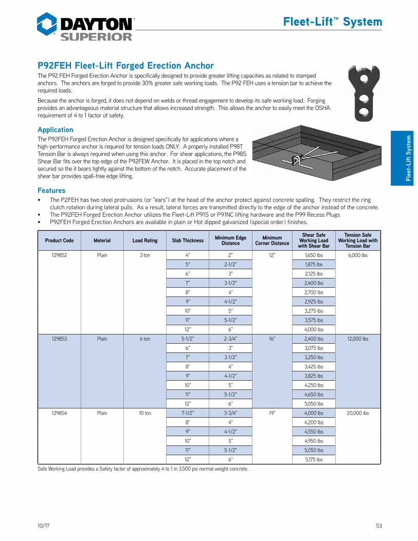
5310/17
Fleet-Lift™ System
Flee
t-Li
ft Sy
stem
P92FEH Fleet-Lift Forged Erection AnchorThe P92 FEH Forged Erection Anchor is specifically designed to provide greater lifting capacities as related to stamped anchors. The anchors are forged to provide 30% greater safe working loads. The P92 FEH uses a tension bar to achieve the required loads. DS_P92FEH
Because the anchor is forged, it does not depend on welds or thread engagement to develop its safe working load. Forging provides an advantageous material structure that allows increased strength. This allows the anchor to easily meet the OSHA requirement of 4 to 1 factor of safety.
ApplicationThe P92FEH Forged Erection Anchor is designed specifically for applications where a high-performance anchor is required for tension loads ONLY. A properly installed P98T Tension Bar is always required when using this anchor. For shear applications, the P98S Shear Bar fits over the top edge of the P92FEW Anchor. It is placed in the top notch and secured so the it bears tightly against the bottom of the notch. Accurate placement of the shear bar provides spall-free edge lifting.
Features• The P2FEH has two steel protrusions (or "ears") at the head of the anchor protect against concrete spalling. They restrict the ring
clutch rotation during lateral pulls. As a result, lateral forces are transmitted directly to the edge of the anchor instead of the concrete.• The P92FEH Forged Erection Anchor utilizes the Fleet-Lift P91S or P91NC lifting hardware and the P99 Recess Plugs• P92FEH Forged Erection Anchors are available in plain or Hot dipped galvanized (special order) finishes.
Product Code Material Load Rating Slab Thickness Minimum Edge Distance
Minimum Corner Distance
Shear Safe Working Load with Shear Bar
Tension Safe Working Load with
Tension Bar129852 Plain 3 ton 4" 2" 12" 1,650 lbs 6,000 lbs
5" 2-1/2" 1,875 lbs
6" 3" 2,125 lbs
7" 3-1/2" 2,400 lbs
8" 4" 2,700 lbs
9" 4-1/2" 2,925 lbs
10" 5" 3,275 lbs
11" 5-1/2" 3,575 lbs
12" 6" 4,000 lbs
129853 Plain 6 ton 5-1/2" 2-3/4" 16" 2,400 lbs 12,000 lbs
6" 3" 3,075 lbs
7" 3-1/2" 3,250 lbs
8" 4" 3,425 lbs
9" 4-1/2" 3,825 lbs
10" 5" 4,250 lbs
11" 5-1/2" 4,650 lbs
12" 6" 5,050 lbs
129854 Plain 10 ton 7-1/2" 3-3/4" 19" 4,000 lbs 20,000 lbs
8" 4" 4,200 lbs
9" 4-1/2" 4,550 lbs
10" 5" 4,950 lbs
11" 5-1/2" 5,050 lbs
12" 6" 5,175 lbs
Safe Working Load provides a Safety factor of approximately 4 to 1 in 3,500 psi normal weight concrete.

54 10/17
Fleet-Lift™ System
Fleet-Lift System
P92S Fleet-Lift Sandwich Panel Erection AnchorP92SP Fleet-Lift Sandwich Panel Erection Anchor with Shear PlateThe Fleet-Lift Sandwich Panel Erection Anchor is designed to erect precast, insulated sandwich panels with a minimum loss of insulation. The anchor uses standard Fleet-Lift recess plugs and ring clutches. DS_P92S
The P92S Sandwich Panel Erection Anchor is designed for use with 2", 3" and 4" thick insulated sandwich panels.
The design of the anchor allows it to distribute anchor loads evenly to both concrete wythes. This is accomplished by the use of two specially bent rebars per sandwich panel anchor. The sandwich panel erection anchor, with its unique anchor head shape, in combination with the two bent rebars, transfers both the anchor’s shear and tension loads evenly into each of the concrete wythes.
Place one bent rebar through the anchor’s top hole and the second rebar through the anchor’s bottom hole. The rebar extend from the anchor into the top and bottom wythe of concrete. The two specially bent rebar must be used with the sandwich panel erection anchor to achieve the safe working loads shown.
The P92SP Sandwich Panel Erection Anchor is similar in design and action to the P92S anchor, and has a built-in shear plate. The shear plate improves shear capacity when used in the 2", 3" and 4" thick wythes. DS_P92SP
Both the P92S and P92SP anchors are available in plain or hot-dipped galvanized finish.
P92S Fleet-Lift Sandwich Panel Erection Anchor
A
B
C
D
E
Parallel to Thickness
Perpendicular to Thickness
Top WytheInsulationBottom Wythe
Typical Sandwich Panel Erection Anchor Application
A
E
B
D
F
G
C
P92SP Sandwich Panel Erection Anchor with Shear Plate
To Order:Specify: (1) quantity, (2) name, (3) product code, (4) finish.
Example:200, P92S Fleet-Lift Sandwich Panel Erection Anchor, FL077, hot-dipped galvanized.

5510/17
Fleet-Lift™ System
Flee
t-Li
ft™ S
yste
m
AnchorTonnage
Product Code
ShearPlate A B C D E F G
4-tonFL077 No 6" 3-3/4" 4-3/8" 1-13/16" 5/8" - -
FL230 Yes 6" 3-3/4" 4-3/8" 1-13/16" 5/8" 3" 2"
8-tonFL184 No 6" 4-3/4" 4" 3-3/8" 3/4" - -
FL284G Yes 6" 4-3/4" 4" 3-3/8" 3/4" 3" 3-1/2"
10-ton145569 Yes 7" 4-3/4" 5" 3-3/8" 3/4" - -
145570 Yes 8" 4-3/4" 6" 3-3/8" 3/4" - -
3"
3"
2"
3"
3"
2"
3" x 2" x 3" Panel
2" x 3" x 3" Panel
Fleet Lift Sandwich Panel Erection Anchor Safe Working Loads
Anchor Tonnage
For Anchor
Concrete Compressive
Strength
Insulated Panel
Thickness
Shear Parallel to Thickness
4:1 SF
Shear Parallel
to Thickness 2.66:1 SF
Shear Perpendicular to Thickness
4:1 SFTension
4-ton FL0774,500 psi 2" x 2" x 4" 3,300 lbs 4,9,60 lbs 8,000 lbs
8,000 lbs3,500 psi 3" x 2" x 3" 3,425 lbs 5,150 lbs 8,000 lbs
8-ton FL1844,500 psi 3" x 2" x 3" 3,850 lbs 5,785 lbs 9,900 lbs
16,000 lbs4,500 psi 2" x 2" x 4" 3,450 lbs 5,185 lbs 10,500 lbs
8-ton FL2844,500 psi 4" x 2" x 2" 4600 lbs 6,915 lbs 9,870 lbs
16,000 lbs4,500 psi 3" x 2" x 3" 4,400 lbs 6,915 lbs 8,800 lbs
10-ton145569 4,500 psi 3" x 3" x 3" 4,700 lbs 7,065 lbs 10,900 lbs
20,000 lbs145570 4,500 psi 3" x 4" x 3" 4,400 lbs 6,615 lbs 9,200 lbs
Minimum edge distance is 2'-0"Must use proper tension bar to achieve loads
Rev. 03/18
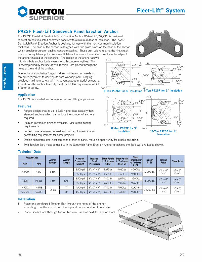
56 10/17
Fleet-Lift™ System
Fleet-Lift System
P92SF Fleet-Lift Sandwich Panel Erection AnchorThe P92SF Fleet-Lift Sandwich Panel Erection Anchor (Patent #5,857,296) is designed to erect precast insulated sandwich panels with a minimum loss of insulation. The P92SF Sandwich Panel Erection Anchor is designed for use with the most common insulation thickness. The head of the anchor is designed with two protrusions on the head of the anchor which provide protection against concrete spalling. These protrusions restrict the ring clutch rotation during lateral pulls. As a result, lateral forces are transmitted directly to the edge of the anchor instead of the concrete. The design of the anchor allows it to distribute anchor loads evenly to both concrete wythes. This is accomplished by the use of two Tension Bars placed through the holes at the end of the anchor. DS_P92SF
Due to the anchor being forged, it does not depend on welds or thread engagement to develop its safe working load. Forging provides maximum safety with its advantageous material structure. This allows the anchor to easily meet the OSHA requirement of 4 to 1 factor of safety.
ApplicationThe P92SF is installed in concrete for tension lifting applications.
Features• Forged design creates up to 33% higher load capacity than
stamped anchors which can reduce the number of anchors required.
• Plain or galvanized finishes available. Meets non-rusting requirements.
• Forged material minimizes rust and can result in eliminating galvanizing requirement for some projects.
• Design eliminates steel near top edge of face of panel, reducing opportunity for cracks occurring.
• Two Tension Bars must be used with the Sandwich Panel Erection Anchor to achieve the Safe Working Loads shown.
Technical DataProduct Code
AnchorTonnage
Anchor Length
Concrete Compressive
Strength
Insulated Panel
Thicknesses
Shear Parallel to Thickness
4:1 SF
Shear Parallel to Thickness 2.66:1 SF
Shear Perpendicular to Thickness
4:1 SF
Tension 4:1 SF
Tension Rebar Shear Rebar
Plain HDG
143700 143701 6-ton 7"3,500 psi 2" x 4" x 2" 2,675 lbs 4,020 lbs 8,200 lbs
12,000 lbs. #4 x 34" Gr 60
#5 x 6" Gr 603,500 psi 3" x 3" x 3" 4,509 lbs 6,765 lbs 9,600 lbs
145081 145566 9-ton 5.75"3,500 psi 3" x 2" x 3" 4,400 lbs 6,615 lbs 8,700 lbs
18,000 lbs. #5 x 42" Gr 60
#6 x 6" Gr 603,500 psi 4" x 2" x 2" 4,600 lbs 6,915 lbs 9,260 lbs
145572 14571812-ton
7" 4,500 psi 3" x 3" x 3" 4,700 lbs 7,065 lbs 10,900 lbs24,000 lbs. #6 x 66"
Gr 60#7 x 6" Gr 60145573 145719 8" 4,500 psi 4" x 4" x 3" 4,400 lbs 6,615 lbs 9,200 lbs
Installation1. Place one configured Tension Bar through the holes of the anchor
extending from the anchor into the top and bottom wythe of concrete.
2. Place Shear Bars through top of Tension Bar slot next to Tension Bars.
9-Ton P92SF for 2" Insulation6-Ton P92SF for 4" Insulation
12-Ton P92SF for 3" Insulation 12-Ton P92SF for 4"
Insulation
3/8"
5/8"
5/8"
3/8"
1/2"
1/2"
1/2"
1/2"
2" Min.
7"
7"
5-3/4"
2" Min.
2-1/2" Min.
2-1/2" Min.
3"
4"
1/2"
1/2"
8"
1/2"
1/2"2-3/8" Min.
2-3/8" Min.
2"
5/8"
5/8"2-1/2" Min.
2-1/2" Min.
4"

5710/17
Fleet-Lift™ System
Flee
t-Li
ft Sy
stem
Rebar for 3" x 2" x 3", 2" x 2" x 4", 3" x 3" x 3" and
3" x 4" x 3" Panels
30˚
OverallLength
P92T Fleet-Lift Sandwich Panel Reinforcing Bars
30˚
4"
5/8"
Min. Radius
8"
32"
Detail A
Detail A
Rebar for 2" x 2" x 2" Panel
Anchor Tonnage Anchor Product Code Rebar4-ton FL077 #4 Grade 60 x 34" overall6-ton 143700 #4 Grade 60 x 34" overall
8 or 9-ton FL184 FL284 145081 #5 Grade 60 x 42" overall10 or 12-ton 145569 145570 145572 45573 #6 Grade 60 x 66" overall

58 10/17
Fleet-Lift™ System
Fleet-Lift System
P92AH Fleet-Lift Erection Anchor with 45˚ Head with Shear PlateThe Dayton Superior P92AH Fleet-Lift Erection Anchor with 45˚ Head and Shear Plate is designed for use when the lifting edge is beveled at a 45˚ angle. The factory installed shear plate eliminates the need for any additional shear reinforcement. DS_P92AH
Installation To install the P92AH anchor, position the anchor a minimum of 3/4" and a maximum of 1-1/2" clear of the casting bed. This can be accomplished using any of the standard recess members. After the anchor has been secured in place, tension reinforcement may be added, if desired. After the concrete has set, removal of the edge form and recess member will expose the head of the anchor for easy attachment of the lifting eye.
Tension ReinforcementDue to the geometry of the anchor the loads shown in the table should not be exceeded, even if additional tension reinforcement is present.
P92AH Erection Anchors are available plain, or hot-dipped galvanized.
Chamfer
Shear Lift
Tension Lift
3/4" Min. to 1-1/2" Max.
45˚
A
D
C
B
45˚
P92AH Fleet-Lift Erection Anchor with 45˚ Head with Shear Plate
To Order:Specify: (1) quantity, (2) name, (3) product code, (4) corrosion resistance, if required.
Example:200, P92AH, Fleet-Lift Erection Anchor with 45˚ head, FL454, hot-dipped galvanized.
P92AH Fleet-Lift Erection Anchor(ton x length)
ProductCode
Precast Concrete
Panel Thickness
Shear Safe Working Load
for Shear
Tension Safe Working Load Anchor Only
Tension Safe Working Load
with Tension Bar
A B C D
2-ton x 8-1/2" long FL4525" Min. 1,750 lbs. 2,650 lbs. 2,650 lbs.
2" 8-1/2" 3/8" 3-1/2"6" 2,150 lbs. 3,850 lbs. 3,850 lbs.
4-ton x 11" long FL4546" Min. 2,400 lbs. 5,200 lbs. 5,200 lbs.
2-1/2" 11" 5/8" 4"8" 3,500 lbs. 6,200 lbs. 6,200 lbs.
8-ton x 13-3/4" long FL458 8" Min. 3,500 lbs. 7,500 lbs. 7,500 lbs. 3-3/4" 13-3/4" 3/4" 5-3/8"
Notes:Safe Working Load provides an approximate factor of safety of 4 to 1 in 3,500 psi normal weight concrete.Safe Working Load is based on the anchor being located in the panel so that the shear plate is 3/4" minimum to 1-1/2" maximum from casting surface.Panel will not hang plumb, as the panel thickness, center of gravity and anchor location will determine the exact angle at which the panel will hang.Due to the design of this anchor, DO NOT attempt to use this anchor at loads higher than shown in this table – even with a properly installed tension bar.Anchor dimensions not shown are the same as the P92P Erection Anchor with Shear Plate of the same load range.
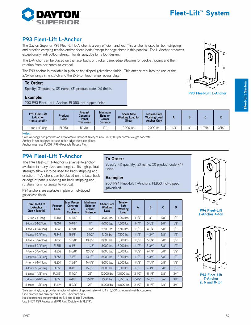
5910/17
Fleet-Lift™ System
Flee
t-Li
ft Sy
stem
P93 Fleet-Lift L-AnchorThe Dayton Superior P93 Fleet-Lift L-Anchor is a very efficient anchor. This anchor is used for both stripping and erection carrying tension and/or shear loads (except for edge shear in thin panels). The L-Anchor produces exceptionally high pullout strength for its size, due to its foot design. DS_P93
The L-Anchor can be placed on the face, back, or thicker panel edge allowing for back-stripping and their rotation from horizontal to vertical.
The P93 anchor is available in plain or hot-dipped galvanized finish. This anchor requires the use of the 2/5-ton range ring clutch and the 2/3-ton load range recess plug.
To Order:Specify: (1) quantity, (2) name, (3) product code, (4) finish.
Example:200 P93 Fleet-Lift L-Anchor, FL050, hot-dipped finish.
P93 Fleet-Lift L-Anchor
(ton x length)ProductCode
Precast Concrete
Panel Thickness
Minimum Edge or Corner
Distance
Shear Safe Working Load for
Shear
Tension Safe Working Load Anchor Only
A B C D
1-ton x 4" long FL050 5" Min. 12". 2,000 lbs. 2,000 lbs. 1-1/4" 4" 1-7/16" 3/16"
Notes:Safe Working Load provides an approximate factor of safety of 4 to 1 in 3,500 psi normal weight concrete.Anchor is not designed for use in thin edge shear conditions.Anchor must use FL051 (P99) Reusable Recess Plug
P94 Fleet-Lift T-AnchorThe P94 Fleet-Lift T-Anchor is a versatile anchor available in many sizes and lengths. Its high pullout strength allows it to be used for back-stripping and erection. T-Anchors can be placed on the face, back or edge of panels allowing for back-stripping and rotation from horizontal to vertical. DS_P94
P94 anchors are available in plain or hot-dipped galvanized finish.
P94 Fleet-Lift L-Anchor
(ton x length)ProductCode
Min. Precast Concrete
Panel Thickness
Minimum Edge or Corner
Distance
Shear Safe Working
Load
Tension Safe
Working Load
A B C D
2-ton x 4" long FL110 4-3/4" 8" 4,000 lbs. 4,000 lbs. 1-1/4" 4" 3/8" 1/2"
2-ton x 5-1/2" long FL059 5-7/8" 11" 4,000 lbs. 4,000 lbs. 1-1/4" 5-1/2" 3/8" 1/2"
4-ton x 4-1/4" long FL848 4-5/8" 8-1/2" 5,500 lbs. 5,500 lbs. 1-1/2" 4-1/4" 5/8" 1/2"
4-ton x 4-3/4" long FL849 5-1/8" 9-1/2" 7,100 lbs. 7,100 lbs. 1-1/2" 4-3/4" 5/8" 1/2"
4-ton x 5-1/4" long FL850 5-5/8" 10-1/2" 8,000 lbs. 8,000 lbs. 1-1/2" 5-1/4" 5/8" 1/2"
4-ton x 5-3/4" long FL851 6-1/8" 11-1/2" 8,000 lbs. 8,000 lbs. 1-1/2" 5-3/4" 5/8" 1/2"
4-ton x 6-1/4" long FL852 6-5/8" 12-1/2" 8,000 lbs. 8,000 lbs. 1-1/2" 6-1/4" 5/8" 1/2"
4-ton x 6-3/4" long FL853 7-1/8" 13-1/2" 8,000 lbs. 8,000 lbs. 1-1/2" 6-3/4" 5/8" 1/2"
4-ton x 7-1/4" long FL854 7-5/8" 14-1/2" 8,000 lbs. 8,000 lbs. 1-1/2" 7-1/4" 5/8" 1/2"
4-ton x 7-3/4" long FL855 8-1/8" 15-1/2" 8,000 lbs. 8,000 lbs. 1-1/2" 7-3/4" 5/8" 1/2"
6-ton x 11-1/8" long FL319* 11-1/2" 23" 12,000 lbs. 12,000 lbs. 2-1/2" 11-1/8" 5/8" 3/4"
8-ton x 6-1/8" long FL055 6-1/8" 12-1/4" 7,950 lbs. 7,950 lbs. 2-1/2" 6-1/8" 3/4" 3/4"
8-ton x 11-1/8" long FL119 11-3/4" 23" 16,000 lbs. 16,000 lbs. 2-1/2" 11-1/8" 3/4" 3/4"
Safe Working Load provides a factor of safety of approximately 4 to 1 in 3,500 psi normal weight concrete.Side notches are provided on 4-ton T-Anchors only.No side notches are provided on 2, 6 and 8-ton T-Anchors.Use 8-10T P99 Recess and P91 Ring Clutch with FL319*.
P94 Fleet-Lift T-Anchor 4-ton
C
B
D
A
P94 Fleet-Lift T-Anchor
2, 6 and 8-ton
C
B
D
A
P93 Fleet-Lift L-Anchor
A
B
DC
To Order:Specify: (1) quantity, (2) name, (3) product code, (4) finish.
Example:200, P94 Fleet-Lift T-Anchors, FL850, hot-dipped galvanized.

60 10/17
Fleet-Lift™ System
Fleet-Lift System
P94H Fleet-Lift H-Anchor 2-TonThe Dayton Superior Fleet-Lift H-Anchor (P94H) is unique in design simplicity. It offers exceptional strength for lifting and handling precast elements, yet can be used in panels as thin as 3". The P94H anchor can be easily preset in the form or “wet set” after the concrete has been poured. The H-Anchor is the strongest and most economical precast lifting anchor available for back-stripping. H-Anchors are available in plain and hot-dipped galvanized finish. DS_P94H
3.3"
2.3"
FL524FL523
B
D
C A3/8"
3/8"
Tension
Load
ShearShear
Optional Reinforcement
Resists Tension and Shear Loads
Optional Reinforcement
P94H Safe Working Load
Product Code
Load Range
Tension Load
4:1 SF
Tension with Reinforcement**
4:1 SF
Shear Load
4:1 SF
Minimum Edge
Distance
Ultimate Mechanical Strength
FL523 2-ton 2,205 lbs. 2,900 lbs. 2,205 lbs. 8" 16,000 lbs.
FL524 2-ton 3,255 lbs. 4,000 lbs. 3,255 lbs. 10" 16,000 lbs.
Safe Working Load provides a factor of safety of approximately 4 to 1. Table is based on a minimum concrete compressive strength of 3,500 psi.* When panel edge installation is required, use the H-Anchor or Two-Hole Anchor with a tension bar. Contact Dayton Superior Technical Assistance for minimum tension reinforcement.** #4 x 12" long placed directly at centerline and against bottom of hole. See sketches at left.
To Order:Specify: (1) quantity, (2) name, (3) product code, (4) corrosion resistance, if required.
Example:200, P94H Fleet-Lift H-Anchor, FL525, hot-dipped galvanized.
P94H Dimensions 2/3 Ton Ring Clutch System (2-Ton Anchor)
Product Code A B C D
MinimumSlab
ThicknessWeightEach
FL523 1.25" 2.30" .35" .56" 3" .28 lbs.
FL524 1.25" 3.30" .38" 1.44" 4" .36 lbs.
P94H H-Anchors are available in plain and hot-dipped galvanized.
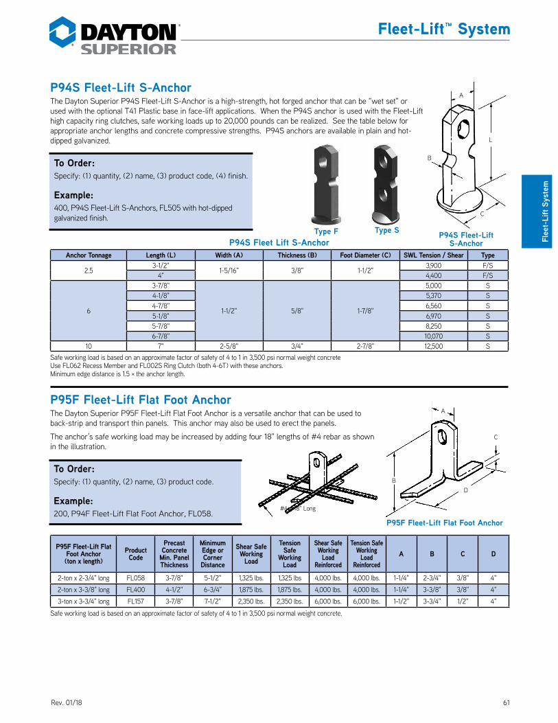
6110/17
Fleet-Lift™ System
Flee
t-Li
ft Sy
stem
P94S Fleet-Lift S-AnchorThe Dayton Superior P94S Fleet‑Lift S‑Anchor is a high‑strength, hot forged anchor that can be “wet set" or used with the optional T41 Plastic base in face‑lift applications. When the P94S anchor is used with the Fleet‑Lift high capacity ring clutches, safe working loads up to 20,000 pounds can be realized. See the table below for appropriate anchor lengths and concrete compressive strengths. P94S anchors are available in plain and hot‑dipped galvanized. DS_P94S
P94S Fleet Lift S-AnchorAnchor Tonnage Length (L) Width (A) Thickness (B) Foot Diameter (C) SWL Tension / Shear Type
2.53‑1/2"
1‑5/16" 3/8" 1‑1/2"3,900 F/S
4" 4,400 F/S
6
3‑7/8"
1‑1/2" 5/8" 1‑7/8"
5,000 S4‑1/8" 5,370 S4‑7/8" 6,560 S5‑1/8" 6,970 S5‑7/8" 8,250 S6‑7/8" 10,070 S
10 7" 2‑5/8" 3/4" 2‑7/8" 12,500 SSafe working load is based on an approximate factor of safety of 4 to 1 in 3,500 psi normal weight concreteUse FL062 Recess Member and FL002S Ring Clutch (both 4‑6T) with these anchors.Minimum edge distance is 1.5 × the anchor length.
P95F Fleet-Lift Flat Foot AnchorThe Dayton Superior P95F Fleet‑Lift Flat Foot Anchor is a versatile anchor that can be used to back‑strip and transport thin panels. This anchor may also be used to erect the panels.
The anchor’s safe working load may be increased by adding four 18" lengths of #4 rebar as shown in the illustration. DS_P95F
P95F Fleet-Lift Flat Foot Anchor(ton x length)
Product Code
Precast Concrete
Min. Panel Thickness
Minimum Edge or Corner
Distance
Shear Safe Working
Load
Tension Safe
Working Load
Shear Safe Working
Load Reinforced
Tension Safe Working
Load Reinforced
A B C D
2‑ton x 2‑3/4" long FL058 3‑7/8" 5‑1/2" 1,325 lbs. 1,325 lbs 4,000 lbs. 4,000 lbs. 1‑1/4" 2‑3/4" 3/8" 4"
2‑ton x 3‑3/8" long FL400 4‑1/2" 6‑3/4" 1,875 lbs. 1,875 lbs. 4,000 lbs. 4,000 lbs. 1‑1/4" 3‑3/8" 3/8" 4"
3‑ton x 3‑3/4" long FL157 3‑7/8" 7‑1/2" 2,350 lbs. 2,350 lbs. 6,000 lbs. 6,000 lbs. 1‑1/2" 3‑3/4" 1/2" 4"
Safe working load is based on an approximate factor of safety of 4 to 1 in 3,500 psi normal weight concrete.
C
B
A
L
C
A
D
P95F Fleet-Lift Flat Foot Anchor
B
#4 x 18" Long
P94S Fleet-Lift S-Anchor
To Order:Specify: (1) quantity, (2) name, (3) product code, (4) finish.
Example:400, P94S Fleet‑Lift S‑Anchors, FL505 with hot‑dipped galvanized finish.
To Order:Specify: (1) quantity, (2) name, (3) product code.
Example:200, P94F Fleet‑Lift Flat Foot Anchor, FL058.
Type F Type S
Rev. 01/18

62 10/17
Fleet-Lift™ System
Fleet-Lift System
P95P Fleet-Lift Plate AnchorThe Dayton Superior P95P Fleet-Lift Plate Anchor is manufactured with a wide base designed to increase its pull-out capacity in concrete. The wide base allows the anchor to have an increased safe working load.
The design of the anchor, with its wide base, permits four #4 rebar, each 18" in length to be easily secured to the insert, as illustrated in the sketch. The addition of the rebar increases the safe working load of the anchor. DS_P95P
P95P anchors are available in plain or hot-dipped galvanized finish.
To Order:Specify: (1) quantity, (2) name, (3) product code, (4) corrosion resistance, if required.
Example:200, P95P Fleet-Lift Plate Anchor, FL847.
P95P Fleet-Lift Plate Anchor(ton x length)
Product Code
Precast Concrete Minimum
Panel Thickness
Minimum Edge or Corner
Distance
Shear Safe Working
Load
Tension Safe
Working Load
Shear Safe Working
Load Reinforced
Tension Safe
Working Load
Reinforced
A B C D
2-ton x 2-1/4" long FL128 3-3/8" 4-1/2" 950 lbs. 950 lbs. 4,000 lbs. 4,000 lbs. 1-1/4" 2-1/4" 3/8" 4"
4-ton x 3" long FL846 4-5/8" 5" 3,575 lbs. 3,575 lbs. 6,000 lbs. 6,000 lbs. 1-1/2" 3" 5/8" 3-3/8"
4-ton x 3-1/2" long FL847 4-5/8" 7" 4,700 lbs. 4,700 lbs. 7,000 lbs. 7,000 lbs. 1-1/2" 3-1/2" 5/8" 3-3/8"
4-ton x 4-3/8" long FL044 5-5/8" 8" 4,725 lbs. 4,725 lbs. 8,000 lbs. 8,000 lbs. 1-1/2" 4-3/8" 5/8" 4"
8-ton x 6-7/8" long FL043 8-1/4" 13-5/8" 10,850 lbs. 10,850 lbs. 10,850 lbs. 10,850 lbs. 2-1/2" 6-7/8" 3/4" 3"
Safe Working Load provides an approximate factor of safety of 4 to 1 in 3,500 psi normal weight concrete.A minimum 3/4" of concrete is required below bottom of insert to achieve load.
P96 Fleet-Lift Two-Hole AnchorThe Dayton Superior P96 Fleet-Lift Two-Hole Anchor is always used in conjunction with the Dayton Superior P98T Tension Bar. The anchor has a bottom hole especially designed to accept the tension bar. Place the P98T Tension Bar through the bottom hole in such a manner that the ends of the tension bar are pointing downward. Fasten the tension bar tight against the bottom side of the hole.
The tension bar distributes the tension forces, developed from the lifting process, deep into the precast concrete. This allows the lifting of very thin and/or low concrete compressive strength panels. DS_P96
Do not use the P96 Two-Hole Anchor in the following situations:1. Without a correct size and located tension bar.2. In the edge of thin panels where shear loads will be applied to the anchor.
P96 Fleet-Lift Two-Hole Anchor(ton x length)
Product Code
Tension Safe Working Load with Tension Bar A B C D E F
2-ton x 2-3/4" long FL190 4,000 lbs 1-1/4" 2-3/4" 3/8" 9/16" 15/16" 9/16"
2-ton x 4" long FL122 4,000 lbs 1-1/4" 4" 3/8" 3/4" 7/8" 9/16"
4-ton x 5-1/2" long FL124 8,000 lbs 1-1/2" 5-1/2" 5/8" 7/8" 1" 11/16"
8-ton x 7" long FL125 16,000 lbs 2-1/2" 7" 3/4" 1-3/16" 1-1/2" 1"
Safe working load is based on an approximate factor of safety of 4 to 1 in 3,500 psi normal weight concrete.
NOTE: Tension reinforcement must be used with Two Hole Anchors.
P96 Fleet-Lift Two Hole Anchor
E
FA
B
C
D
#4 x 18" Long
C
DA
(FL043 only)P95P Fleet-Lift Plate Anchor
B
A
A
D
C
To Order:Specify: (1) quantity, (2) name, (3) product code, (4) corrosion resistance, if required. See P98T Fleet-Lift Tension Bar.
Example:200, P96 Fleet-Lift Two-Hole Anchor, FL124.

6310/17
Fleet-Lift™ System
Flee
t-Li
ft™ S
yste
m
P140 Forged Foot AnchorThe Dayton Superior P140 Forged Foot Anchor is a face lift high capacity 9 Ton insert. The insert utilizes the P91 Ring Clutch 8-12 T.
P140 Steel Anchor can be used with single use T110 Recess Plug (Product Code 126537) or P99 Reusable Recess Plug (8-12 T).
To Order:Specify: (1) quantity, (2) name, (3) Panel Thickness, (4) bottom face exposed aggregate or formliner thickness.
Example:150, P140 Superior Lift Inserts, 9" Panel.
Panel Thickness Anchor Length Plain
Product CodeHDGALV
Product CodeSWL Tension
(4:1 SF)SWL Tension (2.66:1 SF)
SWL Shear (4:1 SF)
5" 3-5/8" 100408 100409 6,860 lbs 10,316 lbs 7,330 lbs
5.5" 4-1/8" 126538 100411 7,690 lbs 11,564 lbs 7,920 lbs
6" 4-5/8" 126539 100412 8,450 lbs 12,707 lbs 8,750 lbs
6.25" 4-7/8" 126540 100413 8,790 lbs 13,218 lbs 8,510 lbs
6.5" 5-1/8" 126541 100414 9,280 lbs 13,955 lbs 9,700 lbs
7" 5-5/8" 126542 100415 10,140 lbs 15,248 lbs 10,640 lbs
7.25" 5-7/8" 126543 100416 10,600 lbs 15,940 lbs 11,120 lbs
7.5" 6-1/8" 126544 100417 11,050 lbs 16,617 lbs 11,590 lbs
8" 6-5/8" 126545 100418 11,950 lbs 17,970 lbs 12,390 lbs
8.25" 6-7/8" 126546 100419 12,420 lbs 18,000 lbs 12,250 lbs
8.5" 7-1/8" 126547 100420 12,850 lbs 18,000 lbs 12,640 lbs
9" 7-5/8" 126548 100421 13,750 lbs 18,000 lbs 13,530 lbs
10" 7-7/8" 126549 100422 16,420 lbs 18,000 lbs 13,590 lbs
Safe Working Load in 3,500 psi normal weight concrete
T275 Tilt-Up AnchorThe Dayton Superior T275 Tilt Up Anchor consists of a dual forged foot anchor assembled with a plastic recess plug and two plastic supports. The insert is a directional insert used parallel to the height of the panel. The T275 inserts are shipped assembled, ready to install and sized to the panel thickness.
Concrete Strength/Safety Factor
Safe Working Load
Structural Panel Thickness
7-1/4" - 9" 9-1/4" - 12"
2,500 psi concrete and 2:1 SF
Tension 20,100 lbs 24,000 lbsShear 24,000 lbs 24,000 lbs
3,000 psi concrete and 2:1 SF
Tension 22,050 lbs 24,000 lbsShear 24,000 lbs 24,000 lbs
3,000 psi concrete and 2.5:1 SF
Tension 24,000 lbs 24,000 lbsShear 17,639 lbs 24,000 lbs
3,000 psi concrete and 4:1 SF
Tension 11,024 lbs 15,718 lbsShear 15,299 lbs 17,250 lbs
4,000 psi concrete and 4:1 SF
Tension 12,731 lbs 16,200 lbsShear 17,250 lbs 17,250 lbs
Note: Mechanical Capacity of steel anchor is 69,000 lbs in shear and 64,800 lbs in tension
T275 Tilt-Up Anchor
To Order:Specify:(1) Quantity, (2) Name, (3) Panel Thickness, (4) Product Code
Example:150, T275 Tilt-Up Anchors, 7-1/4", 146553
P140 Forged Foot Anchor
Note: DO NOT use this anchor with P99D single use void former.
Rev. 03/18

64 10/17
Fleet-Lift™ System
Fleet-Lift System
P98S Fleet-Lift Shear BarThe Dayton Superior P98S Fleet-Lift Shear Bar is designed and manufactured especially for use with Fleet-Lift Erection Anchors. It is a simple, easy to use, yet very efficient design that transfers shear forces from the erection process deeper into the edge of a precast concrete panel. It is stronger and less expensive than a shear bar fabricated from reinforcing steel. DS_P98S
The design of the shear bar allows it to fit over the top edge of an erection anchor. It is placed in the top notch and secured so that it bears tightly against the bottom of the notch. Accurate placement of the shear bar provides for spall-free edge lifts.
The P98S Shear Bar is available to fit 2, 4 and 8-ton Fleet-Lift Erection Anchors. Available in plain or hot-dipped galvanized finish.
Anchor Tonnage
ProductCode
Shear BarDiameter
MinimumPanel
Thickness
Dimensions
H L
2 to 3-ton FL140 1/2" 4" 2-1/2" 13-7/8"
4 to 6-ton FL141 1/2" 5-1/2" 3-5/16" 13-7/8"
8 to 10-ton FL142 1/2" 7-1/2" 4-15/16" 13-7/8"
P98T Fleet-Lift Tension BarThe Dayton Superior P98T Fleet-Lift Tension Bar is used with various Fleet-Lift Anchors to provide a simple, inexpensive method of distributing tension forces (lifting) deep into a precast member. DS_P98T
Anchor Tonnage
Tension Bar
(Grade 60)
L=Overall Length of P98T Tension Bar
3,000 psi 4,000 psi 5,000 psi
1-ton or 2-ton #3 32" 28" 26"
3-ton or 4-ton #4 44" 38" 34"
6-ton or 8-ton #6 66" 56" 50"
10-ton or 12-ton #8 110" 95" 85"
L = Overall length of tension bar based on concrete compressive strength at time of lift.
30˚
L
Fasten tension bar tight
against the bottom side of
hole.
Correct Installation of Tension Bar
(Installed with equal length legs.)
P98S Fleet-Lift Shear Bar
H
LTypical Shear Bar
ApplicationErection Anchor Shear Bar
Top View
CL
Minimum 3/4" Concrete Cover
Equal
EqualShear Bar
Erection Anchor
Section View
To Order:Specify: (1) quantity, (2) name, (3) product code, (4) corrosion resistance, if required.
Example:200 P98S Fleet-Lift Shear Bar, FL141, hot-dipped galvanized.

6510/17
Fleet-Lift™ System
Flee
t-Li
ft Sy
stem
P99 Fleet-Lift Reusable Recess PlugThe Dayton Superior P99 Fleet-Lift Reusable Recess Plug is molded from an elastomeric thermal-set urethane for multiple reuse. DS_P99
Embedded in the recess plug is a stainless steel stud that securely captures a Fleet-Lift Anchor, providing a positive connection to the form during the placement of concrete. Attachment to the form is accomplished with a P100 Holding Rod and P101 Fleet-Lift Holding Plate.
P99 Recess Plugs are resistant to heat and form release agents encountered in a precast plant.
P100 Fleet-Lift Holding Plate and P101 Fleet-Lift Holding RodDS_P100 DS_P101
P100 Fleet-Lift Holding PlateAnchor Tonnage
Product Code A B C
1-ton FL160 5/8"" 2-3/4" 10mm
2-3 ton FL160 5/8" 2-3/4" 10mm
4-6 ton FL144 1-1/4" 3-3/8" 10mm
8-10 ton FL111 1-3/4" 4-7/8" 12mm
P101 Fleet-Lift Holding Rod
Anchor TonnageRecess Plug
MaterialProduct Code
Standard Rod
Length
Thread Diameter and Type
1, 2, 4, 6, 8 and 12-ton Urethane FL131 6" 3/8" Coil
1, 2, 4, 6, 8 and 12-ton Steel FL131C 6" 1/2" Coil
Note: Holding Rod may be special ordered in longer lengths.
To Order:Specify: (1) quantity, (2) name, (3) product code.
Example:200, P100 Fleet-Lift Holding Plates, FL144.
Section View
Stainless Steel Stud
P99 Fleet-Lift Reusable Recess Plug
E
F
D
B
AC
Typical Reusable Recess Plug Application
To Order:Specify: (1) quantity, (2) name, (3) product code.
Example:200, P99 Fleet-Lift Reusable Recess Plug, FL062.
Anchor Tonnage
Product Code A B C D E F
1-ton FL051 1-11/16" 1-3/4" 4-1/16" 3/16" 1-3/16" 3/8"
2-3 ton FL200 1-11/16" 1-3/4" 4-1/16" 3/8" 1-3/16" 3/8"
4-6 ton FL062 2-1/8" 2-5/16" 5-3/16" 5/8" 1-11/32" 3/8"
8-12 ton FL121 3-1/8" 3-5/16" 7-13/16" 3/4" 1-31/32" 3/8"
Note: Recess Plug style FL051 is used with the 1-ton L-Anchor and 2-ton Ring Clutch combination ONLY.
A
C
B
P100 Fleet-Lift Holding Plate
P101 Fleet-Lift Holding Rod
6" Standard
Fixed Wing Nut
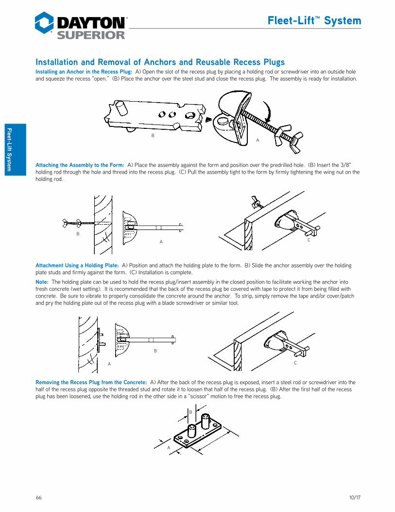
66 10/17
Fleet-Lift™ System
Fleet-Lift System
Installation and Removal of Anchors and Reusable Recess PlugsInstalling an Anchor in the Recess Plug: A) Open the slot of the recess plug by placing a holding rod or screwdriver into an outside hole and squeeze the recess “open.” (B) Place the anchor over the steel stud and close the recess plug. The assembly is ready for installation.
Attaching the Assembly to the Form: A) Place the assembly against the form and position over the predrilled hole. (B) Insert the 3/8" holding rod through the hole and thread into the recess plug. (C) Pull the assembly tight to the form by firmly tightening the wing nut on the holding rod.
Attachment Using a Holding Plate: A) Position and attach the holding plate to the form. B) Slide the anchor assembly over the holding plate studs and firmly against the form. (C) Installation is complete.
Note: The holding plate can be used to hold the recess plug/insert assembly in the closed position to facilitate working the anchor into fresh concrete (wet setting). It is recommended that the back of the recess plug be covered with tape to protect it from being filled with concrete. Be sure to vibrate to properly consolidate the concrete around the anchor. To strip, simply remove the tape and/or cover/patch and pry the holding plate out of the recess plug with a blade screwdriver or similar tool.
Removing the Recess Plug from the Concrete: A) After the back of the recess plug is exposed, insert a steel rod or screwdriver into the half of the recess plug opposite the threaded stud and rotate it to loosen that half of the recess plug. (B) After the first half of the recess plug has been loosened, use the holding rod in the other side in a “scissor” motion to free the recess plug.
BA
A
B
B
A C
B
A C

6710/17
Fleet-Lift™ System
Flee
t-Li
ft Sy
stem
P99C Fleet-Lift Cast Steel Recess PlugThe Dayton Superior P99C Fleet-Lift Cast Steel Recess Plug is designed for high reuse, high curing temperatures and cold weather applications. The recess Plug uses a Steel Wedge (P102) through the anchor eye to securely hold the anchor in place. A Foam Strip (P103) fits over the head of the anchor to prevent concrete from entering the void. DS_P99C
The recess plug/anchor assembly is secured to the form work with the 1/2" diameter Holding Rod (P101) or simply nailed to the form. Recess plug, steel wedge and foam insert are sold separately.
P102 Steel Wedge
P99C Cast Steel Recess Plug
P99C Fleet-Lift Cast Steel Recess Plug Assembly Sequence
P103 Foam
Typical Fleet-Lift Anchor
P103 Fleet-Lift Foam
DS_P103
P99C Fleet-Lift Cast Steel Recess Plug
A
C
B
3/8" Dia. (1/2" dia. optional)
P102 Fleet-Lift Steel Wedge
DS_P102
To Order:Specify: (1) quantity, (2) name, (3) product code.
Example:200, P99C Fleet-Lift Cast Steel Recess Plug, FL100.
P99C Fleet-Lift Cast Steel Recess PlugAnchor Tonnage
Product Code A B C
2-3 ton FL078 1-7/8" 1-3/4" 4"
4-6 ton FL100 2-3/8" 2-3/8" 5-3/8"
8-12 ton FL015 3-3/8" 3-3/8" 7-3/8"
P102 Steel WedgeAnchor Tonnage
Product Code
2-3 ton FL017
4-6 ton FL084
8-12 ton FL085
P103 FoamAnchor Tonnage
Product Code
2-3 ton FL087
4-6 ton FL069
8-12 ton FL091

68 10/17
Fleet-Lift™ System
Fleet-Lift System
Installation and Removal of the Fleet-Lift Cast Steel Recess PlugInstalling the Cast Steel Recess Plug to an Anchor: A) Place the foam strip over the top of the anchor. (B) Place the anchor and foam into the recess slot . (C) Slide the curved steel wedge into the top of the recess plug and through the anchor’s “eye” and wedge tightly.
Attaching the Recess Plug/Anchor Assembly to the Form: A) Place the assembly over the predrilled hole. (B) Insert a holding rod through the hole and thread it into the recess plug. Tighten the holding rod against the anchor with the “fixed” wing nut. (C) Tighten the assembly against the form with the “free-running” wing nut.
Removing the Cast Steel Recess Plug: A) Remove the holding rod from the recess plug. (B) Remove the form. (C) Remove the steel wedge by tapping on the small end with a hammer. (D) Thread the holding rod back into the recess plug and tighten until it pushes the recess out of the void.
B
AC
Complete Assembly
D
C
BA
Free-Running NutFixed Nut

6910/17
Fleet-Lift™ System
Flee
t-Li
ft™ S
yste
m
P99D Fleet-Lift™ Disposable Recess Plug (PVC)The Dayton Superior P99D Fleet-Lift Disposable Recess Plug can be used to preset Fleet-Lift face-lift or edge-lift anchors or can be used to “wet set” P94 Anchors. The Cover/Patch fits tightly onto the recess plug to fully protect the unit. The Cover/Patch is concrete gray in color and can be used as a patch over the recess opening for temporary or permanent cover.
Recess Plug Components:The Disposable Recess Plug can be ordered in sets consisting of a body with a preinstalled clip and a lid, or as individual pieces. This gives the system the versatility to meet your requirements without having to order parts that are not needed. DS_P99D
Cover/Patch
Body
Standard Anchor Clip
Disposable Recess Set
P99D Fleet-Lift Disposable Recess Plug
Standard Anchor Clip
B
Cover/Patch
A
C
BodyD
Anchor Tonnage
Product Description Product Code A B C D
1, 2 and 3-ton
Body FL066B — — — 3/8"
Lid FL066L 2-7/16" — 4-1/4" —
Set FL066S 2-7/16" 2" 4-1/4" —
4 and 6-ton
Body FL067B — — — 5/8"
Lid FL067L 2-7/8" — 5-1/2" —
Set FL067S 2-7/8" 2-1/2" 5-1/2" —
8, 10 and 12-ton
Body FL068B — — — 3/4"
Lid FL068L 3-7/8" — 8-5/16" —
Set FL068S 3-7/8" 3-1/2" 8-5/16" —
To Order:Specify: (1) quantity, (2) name, (3) complete sets or individual part, (4) product code.
Example:200, P99D Fleet-Lift Disposable Recess Plug Cover/Patches, FL067S.
Rev. 02/18
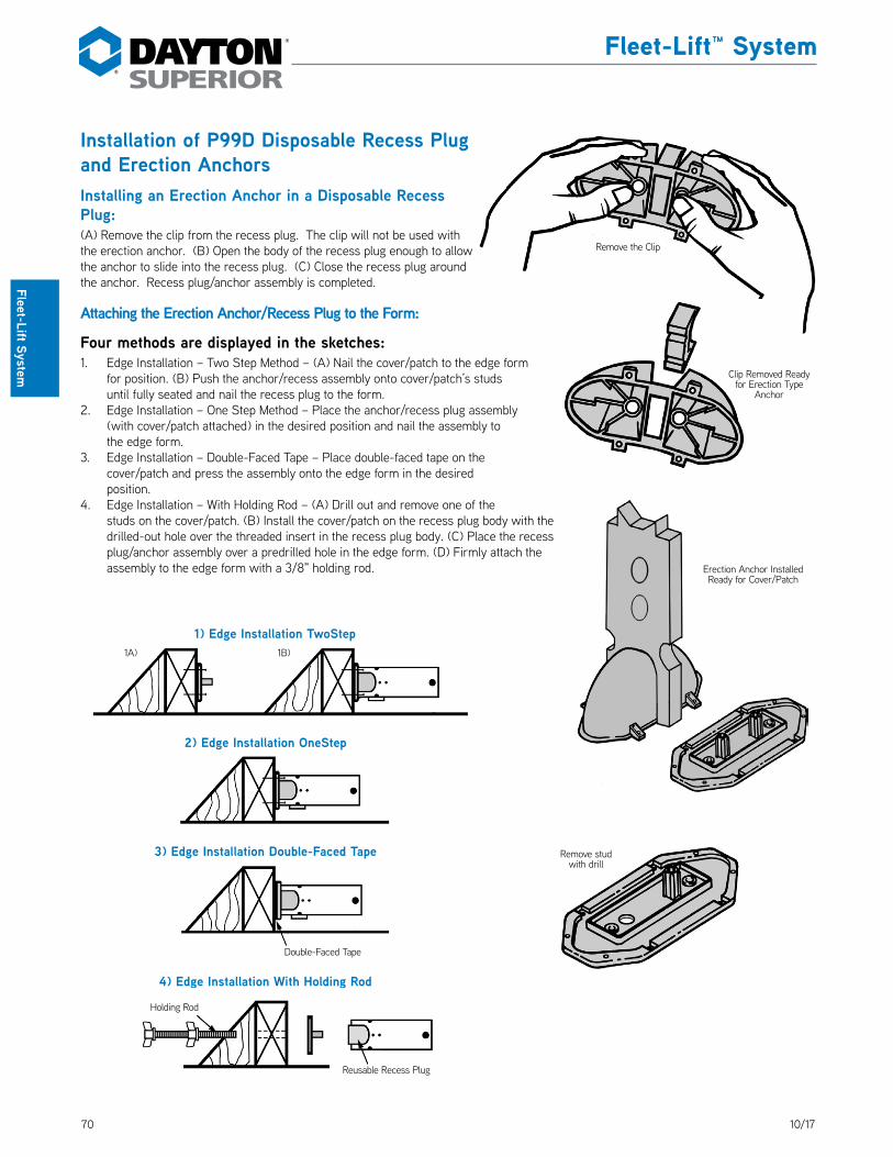
70 10/17
Fleet-Lift™ System
Fleet-Lift System
Installation of P99D Disposable Recess Plug and Erection AnchorsInstalling an Erection Anchor in a Disposable Recess Plug:(A) Remove the clip from the recess plug. The clip will not be used with the erection anchor. (B) Open the body of the recess plug enough to allow the anchor to slide into the recess plug. (C) Close the recess plug around the anchor. Recess plug/anchor assembly is completed.
Attaching the Erection Anchor/Recess Plug to the Form:
Four methods are displayed in the sketches:1. Edge Installation – Two Step Method – (A) Nail the cover/patch to the edge form
for position. (B) Push the anchor/recess assembly onto cover/patch’s studs until fully seated and nail the recess plug to the form.
2. Edge Installation – One Step Method – Place the anchor/recess plug assembly (with cover/patch attached) in the desired position and nail the assembly to the edge form.
3. Edge Installation – Double-Faced Tape – Place double-faced tape on the cover/patch and press the assembly onto the edge form in the desired position.
4. Edge Installation – With Holding Rod – (A) Drill out and remove one of the studs on the cover/patch. (B) Install the cover/patch on the recess plug body with the drilled-out hole over the threaded insert in the recess plug body. (C) Place the recess plug/anchor assembly over a predrilled hole in the edge form. (D) Firmly attach the assembly to the edge form with a 3/8" holding rod.
Remove the Clip
Clip Removed Ready for Erection Type
Anchor
Erection Anchor Installed Ready for Cover/Patch
Remove stud with drill
2) Edge Installation OneStep
4) Edge Installation With Holding Rod
Holding Rod
Reusable Recess Plug
3) Edge Installation Double-Faced Tape
Double-Faced Tape
1A) 1B)
1) Edge Installation TwoStep
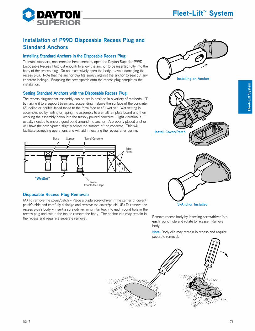
7110/17
Fleet-Lift™ System
Flee
t-Li
ft Sy
stem
Installation of P99D Disposable Recess Plug and Standard AnchorsInstalling Standard Anchors in the Disposable Recess Plug:To install standard, non-erection head anchors, open the Dayton Superior P99D Disposable Recess Plug just enough to allow the anchor to be inserted fully into the body of the recess plug. Do not excessively open the body to avoid damaging the recess plug. Note that the anchor clip fits snugly against the anchor to seal out any concrete leakage. Snapping the cover/patch onto the recess plug completes the installation.
Setting Standard Anchors with the Disposable Recess Plug:The recess plug/anchor assembly can be set in position in a variety of methods: (1) by nailing it to a support beam and suspending it above the surface of the concrete, (2) nailed or double-faced taped to the form face or (3) wet set. Wet setting is accomplished by nailing or taping the assembly to a small template board and then working the assembly down into the freshly poured concrete. Light vibration is usually needed to ensure good bond around the anchor. A properly placed anchor will have the cover/patch slightly below the surface of the concrete. This will facilitate screeding operations and will aid in locating the recess after curing.
Disposable Recess Plug Removal:(A) To remove the cover/patch – Place a blade screwdriver in the center of cover/patch’s side and carefully dislodge and remove the cover/patch. (B) To remove the recess plug’s body – Insert a screwdriver or similar tool into each round hole in the recess plug and rotate the tool to remove the body. The anchor clip may remain in the recess and require a separate removal.
“WetSet”Nail or
Double-face Tape
Block Support Top of Concrete
Edge Form
Installing an Anchor
Install Cover/Patch
S-Anchor Installed
Remove recess body by inserting screwdriver into each round hole and rotate to release. Remove body.
Note: Body clip may remain in recess and require separate removal.

72 10/17
Fleet-Lift™ System
Fleet-Lift System
P99D Temporary Cover/Patch InstallationThe Dayton Superior P99-D Cover/Patch can be used as a temporary cover to keep sand, rain, snow, debris, etc., out of the recess. Under normal precast plant yard conditions, it will stay in place without adhesive.
When planning to use the cover/patch as a temporary cover, be careful when removing the cover to avoid damage. Simply replace the cover/patch into the formed recess, flush with the surface of the concrete. A silicone adhesive may be used on the inner rim of the recess to prevent water from entering the recess.
Permanent Cover/Patch InstallationWhen used as a permanent patch, the cover/patch eliminates the need to grout and will protect the anchor from the environment. The light gray color of the unit will blend with most normal concrete, or it can be painted to closely match other color applications.
When anticipating the use of the cover/patch as a permanent application, be careful during removal to protect the integrity of the concrete around the perimeter of the recess. An application of a silicone or other type adhesive to the inner rim of the recess will seal out the elements or other contaminants. If the recess plug/anchor assembly was installed flush with the concrete surface, the cover/patch will be flush in its permanent position. Future access to the anchor is easily accomplished by removing the cover as described earlier.
Additional cover/patches may be purchased separately, if required.
Protective Cap for Reusable Recess PlugsThe cover/patch can be used as a protective cap for the reusable recess plug. This will protect the recess plug and will eliminate the use of duct tape to cover the back of the recess plug. After installing the anchor in the recess plug, snap the cover/patch onto the recess plug. The cover/patch can be ordered separately for this purpose and can be used and reused many times in this type of installation.
Support Rim: use silicone adhesive
on this area for permanent or water
tight patch
Reinstalled as a temporary or permanent patch
T-Anchor
Reusable Plastic Recess Plug
Disposable Cover/Patch
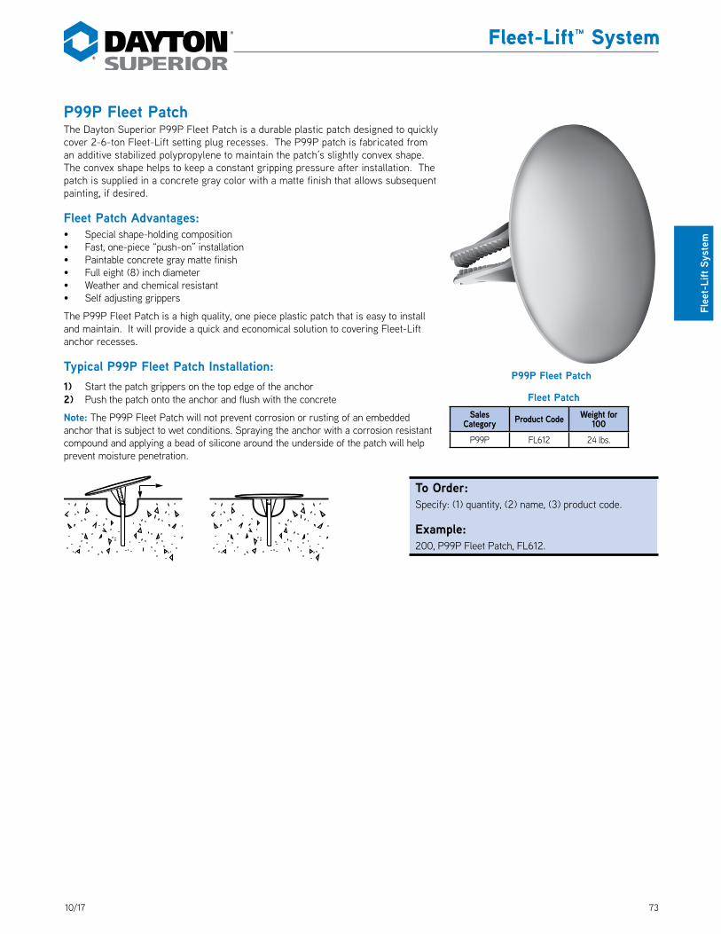
7310/17
Fleet-Lift™ System
Flee
t-Li
ft Sy
stem
P99P Fleet PatchThe Dayton Superior P99P Fleet Patch is a durable plastic patch designed to quickly cover 2-6-ton Fleet-Lift setting plug recesses. The P99P patch is fabricated from an additive stabilized polypropylene to maintain the patch’s slightly convex shape. The convex shape helps to keep a constant gripping pressure after installation. The patch is supplied in a concrete gray color with a matte finish that allows subsequent painting, if desired. DS_P99P
Fleet Patch Advantages:• Special shape-holding composition• Fast, one-piece “push-on” installation• Paintable concrete gray matte finish• Full eight (8) inch diameter• Weather and chemical resistant• Self adjusting grippers
The P99P Fleet Patch is a high quality, one piece plastic patch that is easy to install and maintain. It will provide a quick and economical solution to covering Fleet-Lift anchor recesses.
Typical P99P Fleet Patch Installation:1) Start the patch grippers on the top edge of the anchor2) Push the patch onto the anchor and flush with the concrete
Note: The P99P Fleet Patch will not prevent corrosion or rusting of an embedded anchor that is subject to wet conditions. Spraying the anchor with a corrosion resistant compound and applying a bead of silicone around the underside of the patch will help prevent moisture penetration.
P99P Fleet Patch
To Order:Specify: (1) quantity, (2) name, (3) product code.
Example:200, P99P Fleet Patch, FL612.
Fleet PatchSales
Category Product Code Weight for 100
P99P FL612 24 lbs.

74 10/17
Fleet-Lift™ System
Fleet-Lift System
P100M Fleet-Lift Magnetic PlateThe Dayton Superior P100M Fleet-Lift Magnetic Plate eliminates the need for drilling setting-bolt holes in steel forms. Installed into a rubber base is a set of strong, reliable magnets. These magnets, along with an attachment stud and setting screw, work together to hold a Fleet-Lift anchor tightly in position during the placement of concrete. DS_P100M
The P100M Magnetic Plate is available in three sizes to fit the three P99 Fleet-Lift Recess Plugs.
P100MS Setting ScrewProvided with 3/8" coil threads and used to attach the magnetic setting plate to the P99 Recess Plug, this unit has either a slot or hex in the head. DS_P100MS
Use the 1-1/2" long setting screw with the 1, 2 and 3-ton system and the 2-3/8" long setting screw with both the 4 to 6-ton and the 8 to 10-ton systems.
P100M Fleet-Lift Magnetic Plate Installation
P104F Fleet-Lift One Piece Magnetic RecessThe Dayton Superior P104F One Piece Magnetic Recess allows installation of the Fleet anchors in a metal face form using a one piece rubber recess with magnets imbedded in the top of the recess. Available in 2T, 4T and 8T products.
DS_P104
P100MS Setting Screw
1. Attach Fleet-Lift Anchor to recess plug. 2. Push recess plug onto setting stud of the magnet using the non-threaded middle hole.
3. Place the P110MS Setting Screw through the hole in setting plate, securing setting plate tightly to recess plug.
4. Carefully set complete anchor assembly into proper position in the form.
P100M Fleet-Lift Magnetic Plate
Setting Stud
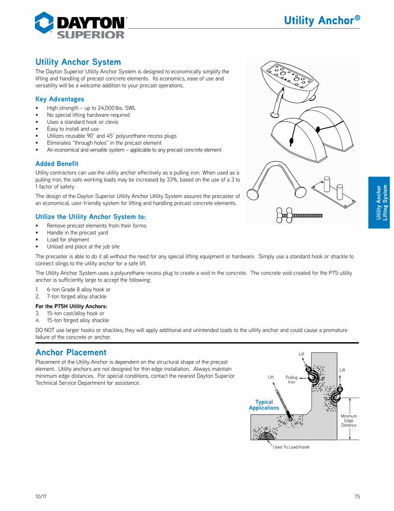
7510/17
Utility Anchor®
Utili
ty A
ncho
r Li
fting
Sys
tem
Utility Anchor SystemThe Dayton Superior Utility Anchor System is designed to economically simplify the lifting and handling of precast concrete elements. Its economics, ease of use and versatility will be a welcome addition to your precast operations.
Key Advantages• High strength – up to 24,000 lbs. SWL• No special lifting hardware required• Uses a standard hook or clevis• Easy to install and use• Utilizes reusable 90° and 45° polyurethane recess plugs• Eliminates “through holes” in the precast element• An economical and versatile system – applicable to any precast concrete element
Added BenefitUtility contractors can use the utility anchor effectively as a pulling iron. When used as a pulling iron, the safe working loads may be increased by 33%, based on the use of a 3 to 1 factor of safety.
The design of the Dayton Superior Utility Anchor Utility System assures the precaster of an economical, user-friendly system for lifting and handling precast concrete elements.
Utilize the Utility Anchor System to:• Remove precast elements from their forms• Handle in the precast yard• Load for shipment• Unload and place at the job site
The precaster is able to do it all without the need for any special lifting equipment or hardware. Simply use a standard hook or shackle to connect slings to the utility anchor for a safe lift.
The Utility Anchor System uses a polyurethane recess plug to create a void in the concrete. The concrete void created for the P75 utility anchor is sufficiently large to accept the following:
1. 6-ton Grade 8 alloy hook or2. 7-ton forged alloy shackle
For the P75H Utility Anchors:3. 15-ton cast/alloy hook or4. 15-ton forged alloy shackle
DO NOT use larger hooks or shackles; they will apply additional and unintended loads to the utility anchor and could cause a premature failure of the concrete or anchor.
Anchor PlacementPlacement of the Utility Anchor is dependent on the structural shape of the precast element. Utility anchors are not designed for thin edge installation. Always maintain minimum edge distances. For special conditions, contact the nearest Dayton Superior Technical Service Department for assistance.
Lift Pulling Iron
Lift
Lift
Used To Load/Install
Minimum Edge
Distance
Typical Applications
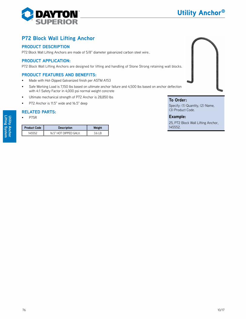
76 10/17
Utility Anchor®
Utility Anchor Lifting System
P72 Block Wall Lifting AnchorPRODUCT DESCRIPTIONP72 Block Wall Lifting Anchors are made of 5/8" diameter galvanized carbon steel wire.. DS_P72
PRODUCT APPLICATION:P72 Block Wall Lifting Anchors are designed for lifting and handling of Stone Strong retaining wall blocks.
PRODUCT FEATURES AND BENEFITS:• Made with Hot-Dipped Galvanized finish per ASTM A153
• Safe Working Load is 7,150 lbs based on ultimate anchor failure and 4,500 lbs based on anchor deflectionwith 4:1 Safety Factor in 4,000 psi normal weight concrete
• Ultimate mechanical strength of P72 Anchor is 28,850 lbs
• P72 Anchor is 11.5" wide and 16.5" deep
RELATED PARTS:• P75R
Product Code Description Weight145552 16.5" HOT DIPPED GALV. 3.6 LB
To Order:Specify: (1) Quantity, (2) Name, (3) Product Code.
Example:25, P72 Block Wall Lifting Anchor, 145552.

7710/17
Utility Anchor®
Utili
ty A
ncho
r Li
fting
Sys
tem
P73SL Thin Slab Utility AnchorPRODUCT DESCRIPTION:The Dayton Superior Thin Slab Utility Anchor is hot forged from carbon steel. The formed head provides for lifting hardware, while a disc-shaped foot is embedded in the concrete. Available in two sizes. DS_P73SL
Due to the anchor being forged, it does not depend on welds or thread engagement to develop its safe working load. Forging provides maximum safety with its advantageous material structure. This allows the anchor to easily meet the OSHA requirement of 4 to 1 factor of safety.
PRODUCT APPLICATION:The P73 is installed in thin slab Precast concrete for tension lifting applications
PRODUCT FEATURES AND BENEFITS:• Plain or galvanized finishes available, meets nonrusting requirements• Can be placed in 4" and greater wall thicknesses (T)• Forged design creates up to 33% higher load capacity than stamped anchors; can reduce the
number of anchors required• Forged material minimizes rust and can result in eliminating galvanizing requirement for
some projects• No special lifting equipment or hardware required. Uses standard Crosby Hook or Clevis• Anchor ultimate mechanical strength is 40,000 lbs.
INSTALLATION:The P73SL Thin Slab Utility Anchor is set in the form using the P76L Void Former.
RELATED PARTS:• P76L Void Former – 139832• Magnetic Setting Plate – 143067• Holding Rod – FL131C
P73SL Thin Slab Utility Anchor Tension Load
Product Code Finish Length (L) Width
(W)Panel Thickness (T)
4" 5" 6" 8"
139528 Galvanized 4.5" 3.00" 3,636 lbs 4,129 lbs 5,820 lbs 5,457 lbs
Safe Working Load provides an approximate factor of safety of 4:1 in 3,500 psi normal weight concrete.
To Order:Specify: (1) Quantity, (2) Name, (3) Product Code, (4) Finish
Example:25, P73SL Thin Slab Utility Anchor, 139528, Galvanized
Anchor Length L
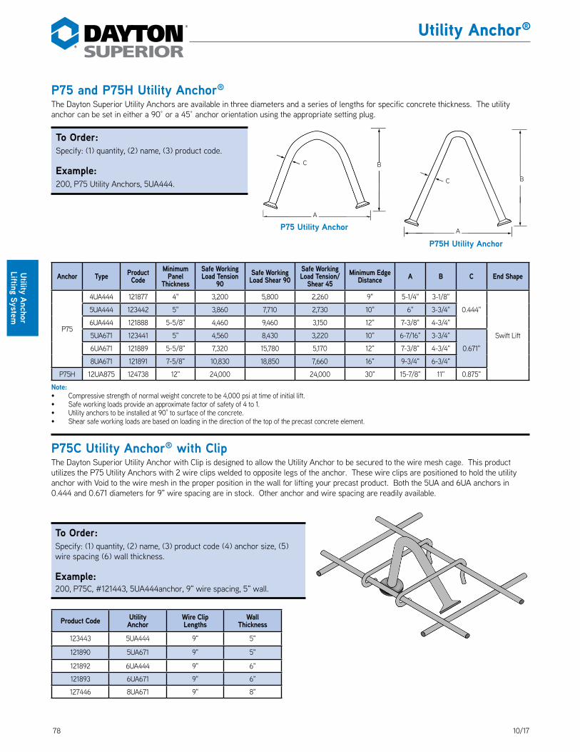
78 10/17
Utility Anchor®
Utility Anchor Lifting System
P75 and P75H Utility Anchor® The Dayton Superior Utility Anchors are available in three diameters and a series of lengths for specific concrete thickness. The utility anchor can be set in either a 90° or a 45° anchor orientation using the appropriate setting plug. DS_P75_P75H
Anchor Type Product Code
Minimum Panel
Thickness
Safe Working Load Tension
90Safe Working Load Shear 90
Safe Working Load Tension/
Shear 45Minimum Edge
Distance A B C End Shape
P75
4UA444 121877 4" 3,200 5,800 2,260 9" 5-1/4" 3-1/8"
0.444"
Swift Lift
5UA444 123442 5" 3,860 7,710 2,730 10" 6" 3-3/4"
6UA444 121888 5-5/8" 4,460 9,460 3,150 12" 7-3/8" 4-3/4"
5UA671 123441 5" 4,560 8,430 3,220 10" 6-7/16" 3-3/4"
0.671"6UA671 121889 5-5/8" 7,320 15,780 5,170 12" 7-3/8" 4-3/4"
8UA671 121891 7-5/8" 10,830 18,850 7,660 16" 9-3/4" 6-3/4"
P75H 12UA875 124738 12" 24,000 24,000 30" 15-7/8" 11" 0.875"
Note: • Compressive strength of normal weight concrete to be 4,000 psi at time of initial lift.• Safe working loads provide an approximate factor of safety of 4 to 1.• Utility anchors to be installed at 90° to surface of the concrete.• Shear safe working loads are based on loading in the direction of the top of the precast concrete element.
P75C Utility Anchor® with ClipThe Dayton Superior Utility Anchor with Clip is designed to allow the Utility Anchor to be secured to the wire mesh cage. This product utilizes the P75 Utility Anchors with 2 wire clips welded to opposite legs of the anchor. These wire clips are positioned to hold the utility anchor with Void to the wire mesh in the proper position in the wall for lifting your precast product. Both the 5UA and 6UA anchors in 0.444 and 0.671 diameters for 9" wire spacing are in stock. Other anchor and wire spacing are readily available. DS_P75C
P75H Utility Anchor
BC
A
BC
A
P75 Utility Anchor
Product Code Utility Anchor
Wire Clip Lengths
Wall Thickness
123443 5UA444 9" 5"
121890 5UA671 9" 5"
121892 6UA444 9" 6"
121893 6UA671 9" 6"
127446 8UA671 9" 8"
To Order:Specify: (1) quantity, (2) name, (3) product code.
Example:200, P75 Utility Anchors, 5UA444.
To Order:Specify: (1) quantity, (2) name, (3) product code (4) anchor size, (5) wire spacing (6) wall thickness.
Example:200, P75C, #121443, 5UA444anchor, 9" wire spacing, 5" wall.
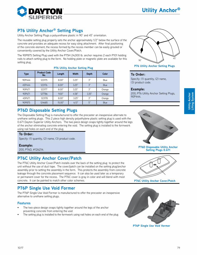
7910/17
Utility Anchor®
Utili
ty A
ncho
r Li
fting
Sys
tem
P76 Utility Anchor® Setting PlugsUtility Anchor Setting Plugs a polyurethane plastic in 90° and 45° orientation. DS_P76
The reusable setting plug properly sets the anchor approximately 1/2" below the surface of the concrete and provides an adequate recess for easy sling attachment. After final positioning of the concrete element, the recess formed by the recess member can be easily grouted or conveniently covered by the Utility Anchor Cover/Patch.
The 90P875 Setting Plug used with the P75H 24,000 lb. anchor requires 2 each P101 holding rods to attach setting plug to the form. No holding plate or magnetic plate are available for this setting plug.
P76 Utility Anchor Setting Plug
Type Product Code No. Length Width Depth Color
90P444 123175 8.00" 3.25" 3" Blue
45P444 123176 8.00" 3.25" 3" Blue
90P671 123177 8.00" 3.25" 3" Orange
90P671 127786 9.00" 4.58" 3.35" Orange
45P671 123178 8.00" 3.25" 3" Orange
90P875 124685 15.00" 6.13" 5" Blue
P76D Disposable Setting PlugsThe Disposable Setting Plug is manufactured to offer the precaster an inexpensive alternate to urethane setting plugs. This 2 piece high density polyethylene plastic setting plug is used with the 0.671 Dayton Superior Utility Anchors. The two piece design snaps tightly together around the legs of the anchor eliminating concrete entering the void. The setting plug is installed to the formwork using nail holes on each end of the plug. DS_P76D
P76C Utility Anchor Cover/PatchThe P76C Utility Anchor Cover/Patch installs over the back of the setting plug to protect the unit without the use of duct tape. The cover/patch can be installed on the setting plug/anchor assembly prior to setting the assembly in the form. This protects the assembly from concrete leakage through the concrete placement sequence. It can also be used later as a temporary or permanent cover for the recess. The P76C cover is gray in color and will blend with most concrete. It can be painted to match other color schemes. DS_P76C
P76P Single Use Void FormerThe P76P Single Use Void Former is manufactured to offer the precaster an inexpensive alternative to urethane setting plugs.
Features• The two-piece design snaps tightly together around the legs of the anchor
preventing concrete from entering the void• The setting plug is installed to the formwork using nail holes on each end of the plug
P76C Utility Anchor Cover/Patch
P76D Disposable Utility Anchor Setting Plugs 0.671
P76P Single Use Void Vormer
To Order:Specify: (1) quantity, (2) name, (3) product code.
Example:200, P76D, #126214.
To Order:Specify: (1) quantity, (2) name, (3) product code.
Example:200, P76 Utility Anchor Setting Plugs, 90P444.
P76 Utility Anchor Setting Plugs
90°45°
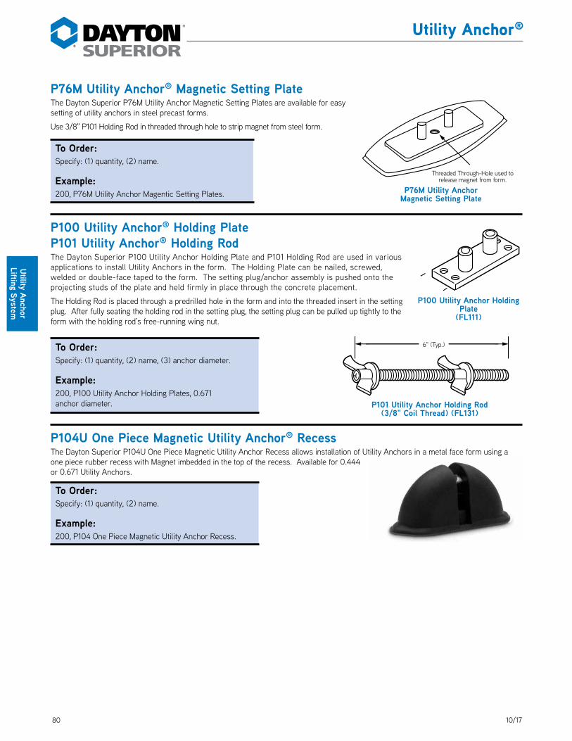
80 10/17
Utility Anchor®
Utility Anchor Lifting System
P76M Utility Anchor® Magnetic Setting PlateThe Dayton Superior P76M Utility Anchor Magnetic Setting Plates are available for easy setting of utility anchors in steel precast forms. DS_P76M
Use 3/8" P101 Holding Rod in threaded through hole to strip magnet from steel form.
P100 Utility Anchor® Holding PlateP101 Utility Anchor® Holding RodThe Dayton Superior P100 Utility Anchor Holding Plate and P101 Holding Rod are used in various applications to install Utility Anchors in the form. The Holding Plate can be nailed, screwed, welded or double-face taped to the form. The setting plug/anchor assembly is pushed onto the projecting studs of the plate and held firmly in place through the concrete placement. DS_P100
The Holding Rod is placed through a predrilled hole in the form and into the threaded insert in the setting plug. After fully seating the holding rod in the setting plug, the setting plug can be pulled up tightly to the form with the holding rod’s free-running wing nut. DS_P101
P104U One Piece Magnetic Utility Anchor® RecessThe Dayton Superior P104U One Piece Magnetic Utility Anchor Recess allows installation of Utility Anchors in a metal face form using a one piece rubber recess with Magnet imbedded in the top of the recess. Available for 0.444 or 0.671 Utility Anchors. DS_P104
P100 Utility Anchor Holding Plate
(FL111)
6" (Typ.)
P101 Utility Anchor Holding Rod(3/8" Coil Thread) (FL131)
P76M Utility Anchor Magnetic Setting Plate
Threaded Through-Hole used to release magnet from form.
To Order:Specify: (1) quantity, (2) name.
Example:200, P76M Utility Anchor Magentic Setting Plates.
To Order:Specify: (1) quantity, (2) name, (3) anchor diameter.
Example:200, P100 Utility Anchor Holding Plates, 0.671 anchor diameter.
To Order:Specify: (1) quantity, (2) name.
Example:200, P104 One Piece Magnetic Utility Anchor Recess.

8110/17
Utility Anchor®
Utili
ty A
ncho
r Li
fting
Sys
tem
Anchor PlacementPlacement of the Utility Anchor is dependent on the structural shape of the precast unit and/or the manufacturer’s preference. The Utility Anchors are not designed for thin edge installations. Always maintain minimum edge distances and adjust anchor capacities if concrete strengths, other than those noted in the capacity chart, are encountered. Refer to edge distance chart.
In-Form setting:1. Assemble setting plug and anchor.2. Affix holding plate (nail, weld, magnetic setting plate, double-face tape) to the form.3. Push the setting plug/anchor assembly onto the holding plate and firmly against the
form.
Through-Form Setting1. Assemble setting plug and anchor.2. Insert holding rod through form and line up setting plug.3. Finger-tighten holding rod and lock assembly in place with the running wing nut.
Wet Setting1. Assemble setting plug holding plate and anchor.2. Use cover/patch or duct tape to seal setting plug cavities.3. Work the assembly down into the wet concrete until the top
surface of the plug is flush with the surface of the concrete.
P76 Utility Anchor® and Double Tee Anchor Setting PlugThe new P76 Setting Plug is a re-usable polyurethane setting plug designed to provide a larger recess in the concrete for the 0.671 Utility Anchors and the Double Tee Anchors. This setting plug is 9.0" in length, 4.5" in width across the top, and 3.3" in depth. This recess member positions the anchor at a 90 degree angle to the surface of the concrete product. The reusable setting plug sets the anchor approximately 1/2" below the top of the concrete. The setting plug is attached to the form with the P101 Holding Rod and/or the P100 Holding Plate. The P76 Setting Plug is stripped from the concrete by placing two 3/8" dia. rods into the holes provided in the plug and using a 'scissor action' to strip the plug from the anchor. DS_P76
Holding PlateSetting Plug
Cover/Patches are available
“Wet” Setting
In-Form Setting
Place “long” stud
at topUtility Anchor Setting Plug
Utility Anchor
Form
Utility Anchor Holding Plate (8-Ton Fleet-Lift Unit)
Through-Form Setting
FormUtility Anchor Setting
Plug
Utility Anchor
Cover/Patch may be added to this installation if future sealing of recess is required. Drill out
one stud of Cover/Patch to pass holding rod through.
Utility Anchor Holding Rod
To Order:Specify: (1) quantity, (2) name, (3)product code.
Example:200, P76 Utility Anchor and Double Tee Anchor Setting Plug, #127786.

82 10/17
Utility Anchor®
Utility Anchor Lifting System
P110 Wire Rope Lifting System™The Wire Rope Lifting System is an economical lifting loop for utility type structures. It is used in face lift applications and is ‘mucked’ into the surface of the concrete. The galvanized wire rope is formed in a figure 8 shape, with the ends of the rope secured by a positive swaged clamp, and a steel band at approximately the mid point to establish the proper shape. The Wire Rope Lifting System is embedded 2/3 of its length into the concrete. The hardware must be standard hook or clevis with a diameter at least twice the rope diameter. Each anchor has a color-coded tag which identifies the SWL in tension of the anchor. DS_P110
Product Features and Benefits:• 7 standard sizes – handles most precast applications up to 10,000 lb SWL• Mucked into surface – no recess members required by the precaster• Uses standard jobsite Crosby Hooks – no hardware purchases required by precaster.• Galvanized wire rope – reduces rusting of the anchor• Can be cut off or left exposed – reduces labor cost for precaster• Economical – for the cost conscious precaster
Part # Description Safe Working Load A B C D E F#127326 0.8 T 1,600# 8.07" 3.7" 3.3" 5.7 2 0.24#127327 1.2 T 2,400# 9.06" 3.9" 3.5" 6.6 2.50 0.275#127328 1.6 T 3,200# 9.84" 5.1" 4.9" 7.1 2.75 0.313#127329 2.0 T 4,000# 11.81" 5.3" 4.9" 8.7 3.13 0.375#127330 2.5 T 5,000# 12.80" 5.5" 4.9" 9.4 3.38 0.375#127331 3.8 T 7,600# 14.57" 6.5" 5.7" 10.7 3.88 0.473#127332 5.0 T 10,000# 14.96" 7.6" 5.7" 11.1 3.80 0.630
NOTE: SWL is 4:1 SF in 3000 psi concrete
Tag Color: White= 0.8T, Red= 1.2T, Pink= 1.6T, Light Green= 2.0T, Dark Green= 2.5T, Emerald Green= 3.8T, Light Yellow= 5.0T
Wire Loop Parellel To Wall Thickness
Anchor Tonnage
Minimum Wall Thickness
Overall Length
Emdedment Depth
Minimum Edge
Distance
Minimum Corner
DistanceSWL @
3000 psiConcrete Strength For
maximum SWLMaximum
SWL0.8 ton 4.0" 8.0625" 5.7" 2.0" 8.75" 1,600 lbs 3,000 psi 1,600 lbs.1.2 ton 4.5" 9.375" 6.5" 2.25" 9.75" 2,400 lbs 3,000 psi 2,400 lbs1.6 ton 4.75" 9.8125" 7" 2.375" 10.5" 2,841 lbs 4,000 psi 3,200 lbs2.0 ton 6" 11.8125" 8.7" 3" 13.25" 3,547 lbs 4,000 psi 4,000 lbs2.5 ton 7.0" 12.34" 9.4" 3.5" 14.25" 4,898 lbs 3,500 psi 5,000 lbs3.8 ton 9.0" 14.5" 10.7" 4.5" 16.25" 6,796 lbs 4,000 psi 7,600 lbs5.0 ton 12" 14.9375" 11.1" 6" 16.75" 9,539 lbs 3,500 psi 10,000 lbs
Wire Loop Perpendicular To Wall Thickness
Anchor Tonnage
Minimum Wall Thickness
Overall Length
Emdedment Depth
Minimum Edge
Distance
Minimum Corner
DistanceSWL @
3000 psiConcrete Strength For
maximum SWLMaximum
SWL
0.8 ton 5.5" 8.0625" 5.7" 2.75" 8.75" 1,600 lbs 3,000 psi 1,600 lbs.1.2 ton 6" 9.375" 6.5" 3" 9.75" 2,400 lbs 3,000 psi 2,400 lbs1.6 ton 6.5" 9.8125" 7" 3.25" 10.5" 2,700 lbs 4,500 psi 3,200 lbs2.0 ton 7" 11.8125" 8.7" 3.5" 13.25" 3,474 lbs 4,000 psi 4,000 lbs2.5 ton 7.5" 12.34" 9.4" 3.75" 14.25" 4,251 lbs 4,500 psi 5,000 lbs3.8 ton 9.0" 14.5" 10.7" 4.5" 16.25" 5,468 lbs 6,000 psi 7,600 lbs5.0 ton 12" 14.9375" 11.1" 6" 16.75" 7,739 lbs 5,000 psi 10,000 lbs
To Order:Specify: (1) quantity, (2) name, (3)product code.
Example:200, P110 Wire Rope Lifting System #127327.
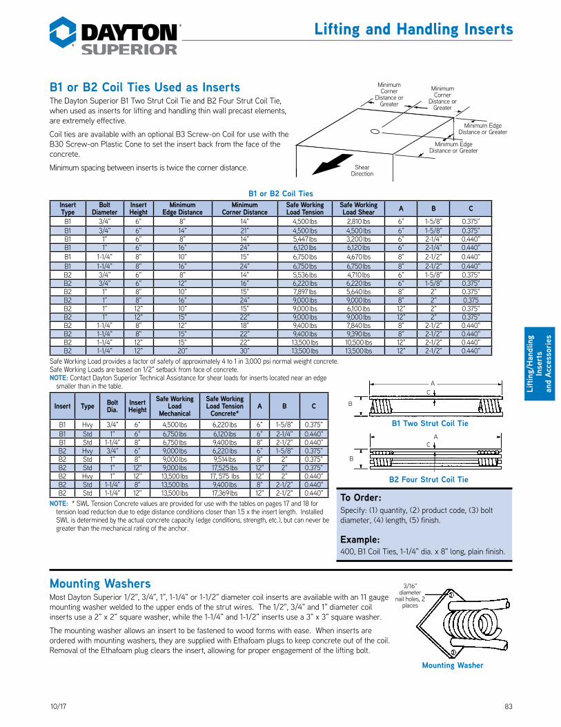
8310/17
Lifting and Handling Inserts
Lifti
ng/H
andl
ing
Inse
rts
an
d Ac
cess
orie
s
B1 or B2 Coil Ties Used as InsertsThe Dayton Superior B1 Two Strut Coil Tie and B2 Four Strut Coil Tie, when used as inserts for lifting and handling thin wall precast elements, are extremely effective. DS_B1B2
Coil ties are available with an optional B3 Screw-on Coil for use with the B30 Screw-on Plastic Cone to set the insert back from the face of the concrete.
Minimum spacing between inserts is twice the corner distance.
B1 or B2 Coil TiesInsert Type
Bolt Diameter
Insert Height
Minimum Edge Distance
Minimum Corner Distance
Safe WorkingLoad Tension
Safe Working Load Shear A B C
B1 3/4" 6" 8" 14" 4,500 lbs 2,810 lbs 6" 1-5/8" 0.375"B1 3/4" 6" 14" 21" 4,500 lbs 4,500 lbs 6" 1-5/8" 0.375"B1 1" 6" 8" 14" 5,447 lbs 3,200 lbs 6" 2-1/4" 0.440"B1 1" 6" 16" 24" 6,120 lbs 6,120 lbs 6" 2-1/4" 0.440"B1 1-1/4" 8" 10" 15" 6,750 lbs 4,670 lbs 8" 2-1/2" 0.440"B1 1-1/4" 8" 16" 24" 6,750 lbs 6,750 lbs 8" 2-1/2" 0.440"B2 3/4" 6" 8" 14" 5,536 lbs 4,710 lbs 6" 1-5/8" 0.375"B2 3/4" 6" 12" 16" 6,220 lbs 6,220 lbs 6" 1-5/8" 0.375"B2 1" 8" 10" 15" 7,897 lbs 5,640 lbs 8" 2" 0.375"B2 1" 8" 16" 24" 9,000 lbs 9,000 lbs 8" 2" 0.375B2 1" 12" 10" 15" 9,000 lbs 6,100 lbs 12" 2" 0.375"B2 1" 12" 15" 22" 9,000 lbs 9,000 lbs 12" 2" 0.375"B2 1-1/4" 8" 12" 18" 9,400 lbs 7,840 lbs 8" 2-1/2" 0.440"B2 1-1/4" 8" 15" 22" 9,400 lbs 9,390 lbs 8" 2-1/2" 0.440"B2 1-1/4" 12" 15" 22" 13,500 lbs 10,500 lbs 12" 2-1/2" 0.440"B2 1-1/4" 12" 20" 30" 13,500 lbs 13,500 lbs 12" 2-1/2" 0.440"
Safe Working Load provides a factor of safety of approximately 4 to 1 in 3,000 psi normal weight concrete.Safe Working Loads are based on 1/2" setback from face of concrete.NOTE: Contact Dayton Superior Technical Assistance for shear loads for inserts located near an edge
smaller than in the table.
Insert Type Bolt Dia.
InsertHeight
Safe Working Load
Mechanical
Safe Working Load Tension
Concrete*A B C
B1 Hvy 3/4" 6" 4,500 lbs 6,220 lbs 6" 1-5/8" 0.375"B1 Std 1" 6" 6,750 lbs 6,120 lbs 6" 2-1/4" 0.440"B1 Std 1-1/4" 8" 6,750 lbs 9,400 lbs 8" 2-1/2" 0.440"B2 Hvy 3/4" 6" 9,000 lbs 6,220 lbs 6" 1-5/8" 0.375"B2 Std 1" 8" 9,000 lbs 9,514 lbs 8" 2" 0.375"B2 Std 1" 12" 9,000 lbs 17,525 lbs 12" 2" 0.375"B2 Hvy 1" 12" 13,500 lbs 17, 575 lbs 12" 2" 0.440"B2 Std 1-1/4" 8" 13,500 lbs 9,400 lbs 8" 2-1/2" 0.440"B2 Std 1-1/4" 12" 13,500 lbs 17,369 lbs 12" 2-1/2" 0.440"
NOTE: * SWL Tension Concrete values are provided for use with the tables on pages 17 and 18 for tension load reduction due to edge distance conditions closer than 1.5 x the insert length. Installed SWL is determined by the actual concrete capacity (edge conditions, strength, etc.), but can never be greater than the mechanical rating of the anchor.
Mounting WashersMost Dayton Superior 1/2", 3/4", 1", 1-1/4" or 1-1/2" diameter coil inserts are available with an 11 gauge mounting washer welded to the upper ends of the strut wires. The 1/2", 3/4" and 1" diameter coil inserts use a 2" x 2" square washer, while the 1-1/4" and 1-1/2" inserts use a 3" x 3" square washer.
The mounting washer allows an insert to be fastened to wood forms with ease. When inserts are ordered with mounting washers, they are supplied with Ethafoam plugs to keep concrete out of the coil. Removal of the Ethafoam plug clears the insert, allowing for proper engagement of the lifting bolt.
3/16" diameter
nail holes, 2 places
Mounting Washer
Shear Direction
Minimum Edge Distance or Greater
Minimum Corner
Distance or Greater
Minimum Edge Distance or Greater
Minimum Corner
Distance or Greater
B1 Two Strut Coil Tie
AC
B
B2 Four Strut Coil Tie
AC
B
To Order:Specify: (1) quantity, (2) product code, (3) bolt diameter, (4) length, (5) finish.
Example:400, B1 Coil Ties, 1-1/4" dia. x 8" long, plain finish.

84 10/17
Lifting and Handling Inserts
Lifting/Handling Inserts
and Accessories
B11 Flat WasherMade from carbon steel. DS_B11
Type Bolt Diameter Safe Working Load SizesB11 Standard 1/2" 1,800 lbs. 3" x 4" x 1/4"
B11 Heavy 1/2" 2,700 lbs. 4" x 5" x 1/4"
B11 Standard 3/4" 2,700 lbs. 4" x 5" x 3/8"
B11 Heavy 3/4" 3,600 lbs. 5" x 5" x 3/8"
B11 Standard 1" 7,200 lbs. 5" x 5" 1/2"
B11 Heavy 1" 15,000 lbs. 7" x 7" x 3/4"
B11 Standard 1-1/4" 10,800 lbs. 5" x 5" x 5/8"
B11 Heavy 1-1/4" 15,000 lbs. 7" x 7" x 3/4"
B11 Standard 1-1/2" 15,000 lbs. 5" x 5" x 3/4"
B11 Heavy 1-1/2" 15,000 lbs. 7" x 7" x 3/4"
Safe Working Load provides a factor of safety of approximately 5 to 1.
B12 Coil Rod• Available high tensile B12 strengths. DS_B12_P49• May be cut with carborundum blades without damaging the threads.• Do not use cutting torch to cut coil rod to length.• Used with B13 or B25 Coil Nuts for making special coil bolts.• B12 requires two B13 or one B25 Coil Nut to develop safe working loads.• B12 standard length is 12'-0" and P49 standard length is 10'-0".• Available in any length up to 20'-0" on special order.
•
•
B13 Coil Nut and B25 Heavy Coil NutDS_B13_P25
Bolt Diameter
B12 Safe Working Load P49 Safe Working Load
Tension Shear Tension Shear1/2" 3,600 lbs. 2,400 lbs. 2,700 lbs. 1,800 lbs.
3/4" 7,200 lbs. 4,800 lbs. – –
1" 15,000 lbs. 10,000 lbs. – –
1-1/4" 22,500 lbs. 15,000 lbs. – –
1-1/2" 27,000 lbs. 18,000 lbs. – –Safe Working Load provides a factor of safety of approximately 5 to 1.
Type Diameter Approx. Height
Safe Working Load tensionUsing ont B13 Nut
Using two B13 Nuts or one B25 Heavy Nut
B13 1/2" Height Height 7/16" 2,400 lbs. 3,600 lbs.
B25 1/2" 1-3/16" – 3,600 lbs.
B13 3/4" 5/8" 3,600 lbs. 7,200 lbs.
B25 3/4" 1-3/16" – 7,200 lbs.
B13 1" 1" 9,600 lbs. 15,000 lbs.
B25 1" 2" – 15,000 lbs.
B13 1-1/4" 1-1/4" 14,400 lbs. 22,500 lbs.
B13 1-1/2" 1-1/2" 19,000 lbs. 27,000 lbs.Safe Working Load provides a factor of safety of approximately 5 to 1.
B11 Flat Washer
Coil Rod
B13 Coil Nut B25 Heavy Coil Nut
Height Height
To Order:Specify: (1) quantity, (2) name, (3) diameter.
Example:200, B13 Coil Nuts, 1" diameter.
To Order:Specify: (1) quantity, (2) type, (3) diameter of bolt to be used, (4) finish.
Example:200, B11 Heavy Flat Washers, 1" bolt dia., plain finish.
To Order:Specify: (1) quantity, (2) name, (3) diameter, (4) length.
Example:200, B12 Coil Rod, 1" dia. x 12'-0" long.

8510/17
Lifting and Handling Inserts
Lifti
ng/H
andl
ing
Inse
rts
an
d Ac
cess
orie
s
B14 Coil BoltB14 coil bolts are available in 1/2", 3/4", 1", 1-1/4" and 1-1/2" diameters with integrally formed heads. DS_B14
Coil Bolts have fast-acting and self-cleaning threads. They can be reused, but will wear and must be regularly inspected for wear and damage. Keep bolts clean and lubricated at all times.
When determining the overall length of a coil bolt, you must consider:
• Height of hardware and/or formwork “grip”• Insert Setback• Minimum coil penetration• The minimum coil penetration shown in the tables below,
apply to all coil products
•
B14 Coil Bolts with Integrally Formed Hex Heads1/2" Diameter
Forged Hex Head Safe Working Load
3/4" Diameter Forged Hex Head
Safe Working Load
1" Diameter Forged Hex Head
Safe Working Load
1-1/4" Diameter Forged Hex Head
Safe Working Load
1-1/2" Diameter Forged Hex Head
Safe Working LoadTension Shear Tension Shear Tension Shear Tension Shear Tension Shear
3,600 lbs. 2,400 lbs. 8,000 lbs. 5,300 lbs. 14,500 lbs. 9,600 lbs. 20,300 lbs. 13,500 lbs. 29,500 lbs. 19,600 lbs.
Minimum CoilPenetration 2"
Minimum CoilPenetration 2-1/4"
Minimum CoilPenetration 2-1/2"
Minimum CoilPenetration 2-1/2"
Minimum CoilPenetration 3"
Bolt LengthMinimum Thread Length
Bolt LengthMinimum Thread Length
Bolt LengthMinimum Thread Length
Bolt LengthMinimum Thread Length
Bolt LengthMinimum Thread Length
3" 2-1/4" 3" 2-3/4" 3" 2-3/4" 3" 2-3/4" – –
4" 3-1/4" 4" 3-3/4" 4" 3-3/4" 4" 3-3/4" 4" 3-3/4"
5" 4-1/4" 5" 4-3/4" 5" 4-3/4" 5" 4-3/4" 5" 4-3/4"
6" 5" 6" 5-3/4" 6" 5-3/4" 6" 5-3/4" 6" 5-3/4"
Over 6" 5" Over 6" 5-3/4" Over 6" 5-3/4" Over 6" 5-3/4" Over 6" 5-3/4"
Safe Working Load provides a factor of safety of approximately 5 to 1.
Hardware Height
Hex Head
Bolt Length
Insert Setback
CoilMin. Coil
Penetration
Minimum Thread Length
Sufficient void beyond coil created by setting bolt,
setting stud or insert locator plug to keep lifting bolt from
“bottoming” out.
To Order:Specify: (1) quantity, (2) type, (3) diameter, (4) length, (5) type.
Example:200, B14 Coil Bolts, 1" dia. X 12" long, forged head.

86 10/17
Lifting and Handling Inserts
Lifting/Handling Inserts
and Accessories
B16 Straight Coil Loop InsertAlthough simple in design and fabrication, the B16 Straight Coil Loop Insert is highly efficient for lifting and handling precast concrete elements. Standard inserts are shown in the chart. Special inserts for use with larger diameter coil bolts, or with loops having longer lengths and of heavier wire can be furnished, if required, on special order. DS_B16
B16 Straight Coil Loop Insert
Bolt Diameter
Insert Length
Minimum Edge
Distance
Minimum Corner
Distance
Safe Working Load
Tension
Safe Working Load Shear
A B
1/2" 3"
2" 5" 810 lbs. 200 lbs.
3" 0.223"3" 5" 1,310 lbs. 325 lbs.
5" 10" 1,950 lbs. 1,050 lbs.
10" 10" 1,950 lbs. 1,350 lbs.
3/4" 4"
2" 5" 1,190 lbs. 200 lbs.
4" 0.306"3" 5" 1,910 lbs. 325 lbs.
5" 10" 1,950 lbs. 1,050 lbs.
8" 10" 1,950 lbs. 2,250 lbs.
1/2" 3/4" or
1"6"
2" 7" 1,420 lbs. 225 lbs.
6" 0.306"3" 7" 2,240 lbs. 425 lbs.
5" 7" 3,600 lbs. 775 lbs.
12" 12" 3,600 lbs. 3,600 lbs.
Safe Working Loads are based on 1/2" setback from face of concrete.Safe Working Load provides a factor of safety of approximately 4 to 1 in 3,000 psi normal weight concrete.Note: Dayton Superior does not recommend the use of 1/2" diameter bolts for lifting/handling of precast panels.
B17 Double Flared Coil Loop Insert The safe working load of the B17 Double Flared Coil Loop Insert is greatly increased over that of a B18 Single Flared Coil Loop. This increase in capacity is achieved by welding a second loop to the same coil. By adding the additional loop, it doubles the cross-sectional area of steel embedded in the concrete and at the same time, increases the area of the shear cone. DS_B17
The design of the B17 insert leaves an open space between the two loops, allowing the B17 insert to “straddle” reinforcing steel or prestressing strands.
Standard sizes are shown in the table and other sizes are available on special order. Minimum spacing between inserts is twice the minimum corner distance.
B17 Double Flared Coil Loop Insert
Bolt Diameter
Minimum Edge
Distance
Minimum Corner
Distance
Safe Working Load
Tension
Safe Working Load
ShearA B C D
1" 1-1/4" or 1-1/2"
5" 15" 4,920 lbs. 2,760 lbs.
12" 0.375" 5-9/16" 5-9/16"9" 15" 9,500 lbs. 6,720 lbs.
12" 18" 9,500 lbs. 9,500 lbs.
18" 27" 9,500 lbs. 9,500 lbs.
1" 1-1/4" or 1-1/2"
5" 15" 4,950 lbs. 2,940 lbs.
12" 0.440" 5-3/4" 5-3/4"9" 15" 9,810 lbs. 7,120 lbs.
12" 18" 11,150 lbs. 10,960 lbs.
18" 27" 13,500 lbs. 13,500 lbs.
Safe Working Loads are based on 1/2" setback from face of concrete. Safe Working Load provides a factor of safety of approximately 4 to 1 in 3,000 psi normal weight concrete.
To Order:Specify: (1) quantity, (2) name, (3) bolt diameter, (4) length, (5) finish.
Example:200, B16 Straight Coil Loop Inserts, 1/2" dia. x 6" long, electro-plated finish
B17 Double Flared Coil Loop Insert
C D
A
B
To Order:Specify: (1) quantity, (2) name, (3) bolt diameter, (4) length, (5) finish.
Example:400, B17 Double Flared Coil Loop Inserts, 1-1/4" dia. x 12-3/8" long, plain finish.
B
B16 Straight Coil Loop Insert
A
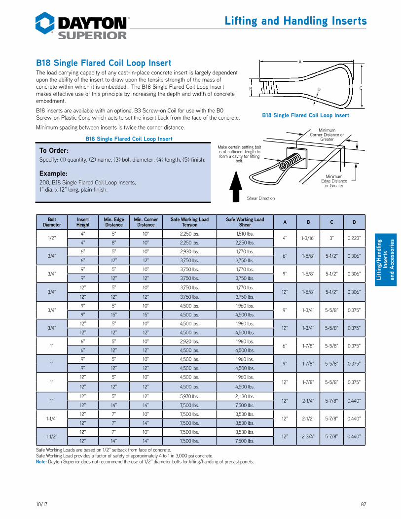
8710/17
Lifting and Handling Inserts
Lifti
ng/H
andl
ing
Inse
rts
an
d Ac
cess
orie
s
B18 Single Flared Coil Loop InsertThe load carrying capacity of any cast-in-place concrete insert is largely dependent upon the ability of the insert to draw upon the tensile strength of the mass of concrete within which it is embedded. The B18 Single Flared Coil Loop Insert makes effective use of this principle by increasing the depth and width of concrete embedment. DS_B18
B18 inserts are available with an optional B3 Screw-on Coil for use with the B0 Screw-on Plastic Cone which acts to set the insert back from the face of the concrete.
Minimum spacing between inserts is twice the corner distance.
B18 Single Flared Coil Loop Insert
Bolt Diameter
Insert Height
Min. Edge Distance
Min. Corner Distance
Safe Working Load Tension
Safe Working Load Shear A B C D
1/2"4" 5" 10" 2,250 lbs. 1,510 lbs.
4" 1-3/16" 3" 0.223"4" 8" 10" 2,250 lbs. 2,250 lbs.
3/4"6" 5" 10" 2,930 lbs. 1,770 lbs.
6" 1-5/8" 5-1/2" 0.306"6" 12" 12" 3,750 lbs. 3,750 lbs.
3/4"9" 5" 10" 3,750 lbs. 1,770 lbs.
9" 1-5/8" 5-1/2" 0.306"9" 12" 12" 3,750 lbs. 3,750 lbs.
3/4"12" 5" 10" 3,750 lbs. 1,770 lbs.
12" 1-5/8" 5-1/2" 0.306"12" 12" 12" 3,750 lbs. 3,750 lbs.
3/4"9" 5" 10" 4,500 lbs. 1,960 lbs.
9" 1-3/4" 5-5/8" 0.375"9" 15" 15" 4,500 lbs. 4,500 lbs.
3/4"12" 5" 10" 4,500 lbs. 1,960 lbs.
12" 1-3/4" 5-5/8" 0.375"12" 12" 12" 4,500 lbs. 4,500 lbs.
1"6" 5" 10" 2,920 lbs. 1,960 lbs.
6" 1-7/8" 5-5/8" 0.375"6" 12" 12" 4,500 lbs. 4,500 lbs.
1"9" 5" 10" 4,500 lbs. 1,960 lbs.
9" 1-7/8" 5-5/8" 0.375"9" 12" 12" 4,500 lbs. 4,500 lbs.
1"12" 5" 10" 4,500 lbs. 1,960 lbs.
12" 1-7/8" 5-5/8" 0.375"12" 12" 12" 4,500 lbs. 4,500 lbs.
1"12" 5" 12" 5,970 lbs. 2, 130 lbs.
12" 2-1/4" 5-7/8" 0.440"12" 14" 14" 7,500 lbs. 7,500 lbs.
1-1/4"12" 7" 10" 7,500 lbs. 3,530 lbs.
12" 2-1/2" 5-7/8" 0.440"12" 7" 14" 7,500 lbs. 3,530 lbs.
1-1/2"12" 7" 10" 7,500 lbs. 3,530 lbs.
12" 2-3/4" 5-7/8" 0.440"12" 14" 14" 7,500 lbs. 7,500 lbs.
Safe Working Loads are based on 1/2" setback from face of concrete. Safe Working Load provides a factor of safety of approximately 4 to 1 in 3,000 psi concrete. Note: Dayton Superior does not recommend the use of 1/2" diameter bolts for lifting/handling of precast panels.
Minimum Corner Distance or
Greater
Minimum Edge Distance
or Greater
Shear Direction
Make certain setting bolt is of sufficient length to form a cavity for lifting
bolt.
B18 Single Flared Coil Loop Insert
A
B CD
To Order:Specify: (1) quantity, (2) name, (3) bolt diameter, (4) length, (5) finish.
Example:200, B18 Single Flared Coil Loop Inserts, 1" dia. x 12" long, plain finish.

88 10/17
Lifting and Handling Inserts
Lifting/Handling Inserts
and Accessories
B33 Double Flared Coil Loop InsertThe safe working load of the B33 Double Flared Coil Loop Insert is identical to the B17 Double Flared Coil Loop. However, its crisscross design will not allow the insert to “straddle” reinforcing steel or prestressing strands. DS_B33
Standard sizes are shown in the table and other sizes are available on special order. Minimum spacing between inserts is twice the minimum corner distance.
B33 Double Flared Coil Loop Insert Selection TableBolt
DiameterMinimum Edge
DistanceMinimum Corner
DistanceSafe Working Load
TensionSafe Working Load
Shear A B C D
1" 1-1/4" or 1-1/2"
5" 15" 4,910 lbs. 2,760 lbs.
12-3/8" 0.375" 5-9/16" 5-9/16"9" 15" 9,500 lbs. 6,720 lbs.
12" 18" 9,500 lbs. 9,500 lbs.
18" 18" 9,500 lbs. 9,500 lbs.
1" 1-1/4" or 1-1/2"
5" 15" 4,970 lbs. 2,940 lbs.
12-1/2" 0.440" 5-3/4" 5-3/4"9" 15" 9,650 lbs. 7,120 lbs.
12" 18" 10,960 lbs. 10,960 lbs.
22" 22" 13,500 lbs. 13,500 lbs.
Safe Working Load provides a factor of safety of approximately 4 to 1 in 3,000 psi normal weight concrete.Safe Working Loads are based on 1/2" setback from face of concrete.
F47 Double Flared Loop InsertThe Dayton Superior F47 Double Flared Loop Insert has been designed for use in 3-1/4" or thicker precast concrete elements. This insert is available for use with 3/4" diameter coil bolts only. DS_F47
Bolt Diameterx
Insert Height
Safe WorkingLoad
TensionConcreteStrength
MinimumEdge
Distance3/4" x 2-3/4" 2,750 lbs. 2,500 psi 6"
Safe Working Load provides a factor of safety of approximately 4 to 1 in normal weight concrete.Safe Working Loads are based on 1/2" setback from face of the concrete.
A
D
B
C
B33 Double Flared Coil Loop Insert
2-3/4" Minimum Height
4-5/8"
3/4" Coil
.223" Diameter
3-1/8"
F47 Double Flared Loop Insert
To Order:Specify: (1) quantity, (2) name, (3) bolt diameter, (4) length, (5) finish.
Example:400, B33 Double Flared Coil Loop Inserts, 1-1/4" dia. x 12-3/8" long, plain finish.
To Order:Specify: (1) quantity, (2) name, (3) finish.
Example:200, F47 Double Flared Loop Inserts, plain finish.

8910/17
Lifting and Handling Inserts
Lifti
ng/H
andl
ing
Inse
rts
an
d Ac
cess
orie
s
F48 Eye Nut, F49 Eye Bolt and F49A Eye BoltThe Dayton Superior F48 Eye Nut is cast from ductile iron that meets ASTM Standard A-536 Grade 80-55-06. The eye nut is cast with coil threads and is intended to be used with B12 Coil Rod that has been cut to the proper length. The eye nut eliminates the need to inventory several different lengths of eye bolts. DS_F48
To make permanent length eye bolts, it is possible to weld lengths of coil rod to the casting. Since improper welding techniques can result in reduced safe working loads, Dayton Superior recommends that you contact your local welding supply house for proper welding instructions and techniques.
The F49 Eye Bolt is an F48 Eye Nut supplied with a specified length of coil rod that has been welded in place. In order to develop the F49 eye bolt’s rated load, the shoulder must be tightened securely against the face of the concrete. DS_F49
The F48 Eye Nut and F49 Eye Bolt are intended for straight tensile loading only; pulling or lifting at an angle drastically reduces the safe working load and is not recommended.
F48 Eye Nut and F49 Eye Bolt Selection TableSafe Working Load
- Tension Coil Rod Diameter A B C D E
2,700 lbs. 1/2" 3-1/4" 1" 1" 3/4" 2"
3,600 lbs. 3/4" 3-1/2" 1" 1" 3/4" 2"
7,200 lbs. 1" 5" 1-1/4" 1-3/4" 1" 3"
10,800 lbs. 1-1/4" 6-1/4" 1-1/2" 2-1/4" 1-1/4" 4"
Safe Working Load provides a factor of safety of approximately 5 to 1.Note: Dayton Superior does not recommend the use of 1/2" diameter bolts for lifting/handling of precast panels.
The F49A Eye Bolt is a forged, carbon steel, one piece, shoulder pattern eye bolt. It is available with 3/4" or 1" diameter coil threads and stocked in 3-1/2" and 6" lengths. Other lengths are available special order. DS_F49A
In order to develop the F49A Eye Bolt’s rated load, the shoulder must be tightened firmly against the face of the concrete. The eye bolt is intended for straight tensile loading only; pulling or lifting at an angle drastically reduces the safe working load and is not recommended. The F49A Eye Bolt meets material requirements of ASTM Standard A-489.
Bolt Diameter Tension Safe Working Load A B C3/4" 3,600 lbs. 2-7/8" 1-1/2" 3" or 6"
1" 6,400 lbs. 3-1/2" 1-3/4" 3"
Safe Working Load provides a factor of safety of approximately 5 to 1.
A C
B
E
D
F48 Eye Nut
F49 Eye Bolt
Leng
th Coil Thread
Weld Area
F49A Eye Bolt
A
B
Length
To Order F48 Eye Nut:Specify: (1) quantity, (2) name, (3) bolt diameter.
Example:200, F48 Eye Nuts, 1" dia. bolt.
To Order F49 or F49A Eye Bolts:Specify: (1) quantity, (2) name, (3) bolt diameter, (4) length.
Example:200, F49 Eye Bolts, 1" dia. x 12" long.

90 10/17
Lifting and Handling Inserts
Lifting/Handling Inserts
and Accessories
P21 Wire Rope LoopThe P21 Dayton Superior Wire Rope Loop provides a fast method for handling precast items. Designed to work with 3/4" and 1" diameter coil inserts under straight tension loads only. Do not use under shear loading conditions, instead, use a swivel lift plate and coil bolt. With proper care, the wire rope loop can be reused. Visual evidence of any deterioration of the wire rope is a safety feature of this product. DS_P21
Diameter x Type of Thread
Safe Working Load Tension
Loop Dimensions
A B C
1/2" Coil 2,000 lbs. 6" 2" 1-1/4"
3/4" Coil 5,200 lbs. 8-3/4" 2-1/2" 1-3/4"
1" Coil 8,000 lbs. 12" 3" 2-1/4"
Safe Working Load provides a factor of safety of approximately 5 to 1.
F53 Thin Slab Coil InsertThe Dayton Superior F53 Thin Slab Coil Insert is designed for lifting thin precast concrete panels from the casting bed and for handling the panels until they are set into their final position. Inserts should be set back 1/2" from the surface of the concrete, maintaining at least 3/4" of concrete below the insert. Minimum spacing between inserts is twice the minimum corner distance. Available in insert heights up to 4". DS_F53
B53 Thin Slab Coil Insert Selection TableBolt
DiameterMinimum Edge
DistanceMinimum
Corner DistanceSafe Working Load Tension
Safe Working Load Shear A B C
3/4" 8" 12" 2,340 lbs. 2,340 lbs. 3" 7-1/8"
0.306"1"
10" 15" 3,520 lbs. 3,460 lbs. 4"
9-3/8"
1-1/4" 9-5/8"
1-1/2" 9-7/8"
Safe Working Load provides a factor of safety of approximately 4 to 1 in 3,000 psi normal weight concrete.Safe Working Loads are based on 1/2" setback from face of concrete.
To Order:Specify: (1) quantity, (2) name, (3) bolt diameter, (4) height, (5) finish.
Example:200, F53 Thin Slab Coil Inserts, 1" dia. x 4" height, plain finish.
P21 Wire Rope LoopDiameter
C B
A
F53 Thin Slab Coil Insert
BAA
A
C15°
To Order:Specify: (1) quantity, (2) name, (3) diameter.
Example:100, P21 Wire Rope Loop, 3/4" dia.coil.

9110/17
Lifting and Handling Inserts
Lifti
ng/H
andl
ing
Inse
rts
an
d Ac
cess
orie
s
F56, F58 and F60 Expanded Coil InsertsExpanded Coil Inserts are fabricated in two, four or six strut versions, as required. A standard coil is welded at one end of the strut wires and on the opposite end, an expanded pitch coil is welded. The expanded pitch coil welded to the more deeply embedded end of the insert, serves to distribute the applied loads over a larger volume of concrete. DS_F56_F58_F60
• Ethafoam Plug installed when mounting washers are ordered.
• Minimum spacing between inserts is twice the minimum corner distance.
• Longer lengths available, if required.
Expanded Coil Insert Selection Table
Insert Type Bolt Diameter
Insert Length
Min. Edge Distance
Min. Corner Distance
Safe Working Load Tension
Safe Working Load Shear A B C
F56 Coil 3/4" 4-1/2"
2-1/2" 6" 1,800 lbs. 680 lbs.
4-1/2" 0.375" 1-1/2"4" 8" 2,220 lbs. 1,380 lbs.
8" 12" 4,250 lbs. 2,760 lbs.
14" 20" 4,250 lbs. 4,250 lbs.
F56 Coil 1" 5-1/2"
2-1/2" 7" 2,000 lbs. 740 lbs.
5-1/2" 0.440" 2-1/2"4" 9" 2,560 lbs. 1,500 lbs.
8" 12" 5,300 lbs. 3,250 lbs.
18" 24" 6,250 lbs. 6,250 lbs.
F58 Coil 1-1/4" 7-1/2"
3" 10" 2,480 lbs. 1,270 lbs.
7-1/2" 0.440" 2-3/4"5" 12" 3,600 lbs. 2,730 lbs.
8" 15" 5,700 lbs. 4,790 lbs.
18" 26" 10,480 lbs. 10,590 lbs.
F60 Coil 1-1/2" 9-1/2"
3" 12" 2,820 lbs. 1,500 lbs.
9-1/2" 0.440" 3-5/8"5" 15" 3,880 lbs. 3,230 lbs.
8" 15" 6,680 lbs. 6,260 lbs.
22" 30" 14,580 lbs. 16,430 lbs.
Safe Working Load provides a factor of safety of approximately 4 to 1 in 3,000 psi normal weight concrete.Safe Working Load is based on a 1/2" setback from face of concrete.
C
AExpanded Pitch Coil
B
F56 Expanded Coil Insert for Coil Threaded Bolts
F56 Insert – 2 StrutsF58 Insert – 4 StrutsF60 Insert – 6 Struts
To Order:Specify: (1) quantity, (2) name, (3) bolt diameter, (4) finish.
Example:200, F60 Expanded Coil Inserts, 1-1/2" diameter, plain finish.

92 10/17
Lifting and Handling Inserts
Lifting/Handling Inserts
and Accessories
F63 Flared Thin Slab Coil InsertThe Dayton Superior F63 Flared Thin Slab Coil Insert is designed for use in very thin slabs or other conditions where a longer insert cannot be used. Inserts should be set back 1/2" from the surface of the concrete, maintaining at least 3/4" of concrete below the insert. Minimum spacing between inserts is twice the minimum corner distance. DS_F63
To Order:Specify: (1) quantity, (2) name, (3) bolt diameter, (4) height, (5) finish.
Example:200, F63 Flared Thin Slab Coil Inserts, 1" dia. x 4-1/2", plain finish.
F63 Flared Thin Slab Coil Insert Selection Table
Bolt Diameter
Insert Length
Minimum Edge
Distance
Minimum Corner
Distance
Safe Working Load
Tension
Safe Working Load
ShearA B C
1/2" 1-3/4" 6" 6" 1,520 lbs. 1,090 lbs. 1-3/4" 4-1/8" 0.223"
3/4" 2-5/16" 8" 8" 2,170 lbs. 1,640 lbs. 2-5/16" 4-7/8" 0.306"
3/4" 3-1/2" 9" 9" 3,570 lbs. 2,600 lbs. 3-1/2" 4-7/8" 0.306"
1" 2-5/16" 8" 8" 2,460 lbs. 1,970 lbs. 2-5/16" 5-1/4" 0.306"
1" 4-1/2" 12" 12" 5,280 lbs. 4,000 lbs. 4-1/2" 5-1/4" 0.306"
Safe Working Load provides a factor of safety of approximately 4 to 1 in 3,000 psi normal weight concrete.Note: Dayton Superior does not recommend the use of 1/2" diameter bolts for lifting/handling of precast panels.
F65 Type L Coil InsertThe Dayton Superior F65 Type L Coil Insert is designed for use in lifting and handling lightweight precast concrete elements. Inserts should be set back 1/2" from the surface of the concrete. Minimum spacing between inserts is twice the minimum corner distance. DS_F65
To Order:Specify: (1) quantity, (2) name, (3) bolt diameter, (4) finish.
Example:200, F65, Type L Coil Inserts, 1/2" diameter, plain finish.
B16 Straight Coil Loop Insert
Bolt Diameter
Insert Length
Minimum Edge
Distance
Minimum Corner
Distance
Safe Working Load
Tension
Safe Working Load
ShearA B C
1/2" 4"
2-1/2" 10" 1,150 lbs. 530 lbs.
4" 2-3/8" 0.223"5" 10" 2250 lbs. 1,230 lbs.
8" 12" 2250 lbs. 1,980 lbs.
3/4" 4"
2-1/2" 10" 1,140 lbs. 600 lbs.
4" 3-3/8" 0.306"5" 10" 2,630 lbs. 1,400 lbs.
8" 12" 3,520 lbs. 2,250 lbs.
Safe Working Load provides a factor of safety of approximately 4 to 1 in 3,000 psi normal weight concrete.Note: Dayton Superior does not recommend the use of 1/2" diameter bolts for lifting/handling of precast panels.Note: Table based on Face Lift usage of inserts.
A
B
C
F63 Flared Thin Slab Coil Insert
F65 Type L Coil Insert
B
C
A

9310/17
Lifting and Handling Inserts
Lifti
ng/H
andl
ing
Inse
rts
an
d Ac
cess
orie
s
T1 Single Pickup InsertDayton Superior T1 Single Pickup Inserts are available with plastic or stainless steel tips and with or without T21 Insert Locator Plugs installed. T1 inserts are designed for use with T12 or T26 Swivel Lifting Plates. Do not use T1 inserts as an edge or end pick-up insert. DS_T1
Height of insert is 3/8" less than the panel’s structural thickness. Standard panel thickness is shown in the chart and other panel thickness is available on special order.
Recommended minimum edge distance is 15". Minimum spacing between inserts is 30".T1 Single Pick-up Insert Selection Table
Bolt Diameter Panel Thickness Safe Working Load
TensionSafe Working Load
Shear
3/4"
4" 2,269 lbs. 4,539 lbs.
5" 3,442 lbs. 5,400 lbs.6" 4,766 lbs. 5,400 lbs.7" 6,227 lbs. 5,400 lbs.8" 7,813 lbs. 5,400 lbs.
1"
4" 2,269 lbs. 4,539 lbs.5" 3,442 lbs. 5,520 lbs.6" 4,766 lbs. 5,520 lbs.7" 6,227 lbs. 5,520 lbs.8" 7,813 lbs. 5,520 lbs.
1-1/4"
4" 2,269 lbs. 4,539 lbs.5" 3,442 lbs. 5,520 lbs.6" 4,766 lbs. 5,520 lbs.7" 6,227 lbs. 5,520 lbs.8" 7,813 lbs. 5,520 lbs.
1-1/2"
4" 2,269 lbs. 4,539 lbs.5" 3,442 lbs. 5,520 lbs.6" 4,766 lbs. 5,520 lbs.7" 6,227 lbs. 5,520 lbs.8" 7,813 lbs. 5,520 lbs.
Safe Working Load provides a factor of safety of approximately 4 to 1 in 3,000 psi normal weight concrete.
P1 Single Pickup InsertDayton Superior P1 Single Pickup Inserts are available with electro galvanized finish, with or without plastic dipped feet. Also available in stainless steel wire with or without plastic dipped feet. Installed T21 Insert Locator. Plugs are optional. P1 inserts are designed for use with T26 Swivel Lifting Plates. Do not use P1 inserts as an edge or end pickup insert.
• Standard insert heights are shown in the chart and other insert heights are available on special order
• Minimum spacing between inserts is twice the minimum corner distance
• Wire diameter = 0.440"
P1 1-1/4" Diameter
Insert Height
Insert Setback1" 1-1/2" 2" 2-1/2" 3"
Tension Shear Tension Shear Tension Shear Tension Shear Tension Shear6" 7,454 lbs. 4,554 lbs. 8,276 lbs. 4,770 lbs. 9,126 lbs. 4,981 lbs. 10,004 lbs. 5,189 lbs. 10,909 lbs. 5,393 lbs.7" 9,126 lbs. 4,981 lbs. 10,004 lbs. 5,189 lbs. 10,909 lbs. 5,393 lbs. 10,909 lbs. 5,593 lbs. 10,909 lbs. 5,791 lbs.8" 10,909 lbs. 5,393 lbs. 10,909 lbs. 5,593 lbs. 10,909 lbs. 5,791 lbs. 10,909 lbs. 5,985 lbs. 10,909 lbs. 6,177 lbs.
Safe Working Load provides a factor of safety of approximately 4 to 1 in 3,000 psi normal weight concrete.
P1 Single Pickup Insert
T1 Single Pickup Insert
To Order:Specify: (1) quantity, (2) name, (3) diameter, (4) panel structural thickness, (5) type of tips.
Example:200, T1 Single Pickup Inserts, 3/4" dia., 5" panel structural thickness, plastic tipped feet.
To Order:Specify: (1) quantity, (2) name, (3) diameter, (4) insert height (5) type of tips, (6) finish.
Example:200, P1 Single Pickup Inserts, 3/4" dia., 6" insert height, plastic tipped feet, galvanized.

94 10/17
Lifting and Handling Inserts
Lifting/Handling Inserts
and Accessories
T3 and T3A End Pickup Inserts DS_T3_T3A
T3 and T3A End Pickup Insert Selection Table
Insert Type Bolt Diameter
Load Condition 4" Panel 5" Panel 5-1/2"
Panel 6" Panel 6-1/2" panel 7" Panel 7-1/2"
Panel 8" Panel
T3A
3/4" SingleTension 1,500 lbs. — — — — — — —
Shear 1,250 lbs. — — — — — — —
1" SingleTension — 3,000 lbs. 3,300 lbs. 3,600 lbs. 3,900 lbs. 4,200 lbs. 4,500 lbs. 4,500 lbs.
Shear — 1,350 lbs. 1,375 lbs. 1,400 lbs. 1,425 lbs. 1,450 lbs. 1,500 lbs. 1,550 lbs.
T3
3/4" DoubleTension 2,500 lbs. — — — — — — —
Shear 1,500 lbs. — — — — — — —
1" DoubleTension — 4,000 lbs. 4,400 lbs. 4,800 lbs. 5,200 lbs. 5,600 lbs. 6,000 lbs. 6,000 lbs.
Shear — 2,100 lbs. 2,250 lbs. 2,400 lbs. 2,550 lbs. 2,700 lbs. 2,850 lbs. 3,000 lbs.
Safe working load provides a factor of safety of approximately 4 to 1 in 3,000 psi normal weight concrete.Safe Working Loads are based on 1/2" setback from face of concrete.
To Order:Specify: (1) quantity, (2) name, (3) diameter.
Example:200, T3 End Pickup Inserts, 1" diameter.
.375" Diameter Loop for Tension
.375" Diameter Loop for Tension
.375" Diameter Shear Bar
12"12"
12"
23"5-1/2"
5-3/4"
11-1/2"
.375" Diameter Shear Bar
T3 End Pickup Insert T3A End Pickup Insert

9510/17
Lifting and Handling Inserts
Lifti
ng/H
andl
ing
Inse
rts
an
d Ac
cess
orie
s
T7S and T7ST Slotted Setting StudsThe Dayton Superior T7S Slotted Setting Stud has a slot to facilitate installation and removal. The T7ST stud has a slot and is drilled 1" deep and tapped with 1/4"-20 threads to allow the stud to be used as an insert setting plug. DS_T7S_T7ST
• Used with standard coil threaded inserts to provide void for B14 coil bolts.
• Made from continuous threaded steel rod.
• Top is cut off square so screed can pass over.
• Threads and slot should be coated with non-staining lubricant to prevent bonding.
• Loosen studs within 2 to 12 hours after concrete placement to ease removal when ready to lift.
• Standard steel sizes are 1/2", 3/4", 1" , 1-1/4" and 1-1/2" diameter x 4" long. Other lengths avai lable on request.
P25 Plastic Setting BoltThe Dayton Superior Plastic Setting Bolt is used to attach 1/2", 3/4" and 1" diameter coil inserts to wood frames. The head of the setting bolt has nail holes allowing easy attachment of the bolt. The plastic setting bolt positions the insert 3/4" from concrete surface. DS_P25
Product Code Bolt Diameter
Length Thread
100210 1/2" 2"
100220 3/4" 3-1/4"
100230 1" 4-3/4"
T8 Lifting Angle• Designed for use with T2 Double Pickup Inserts. DS_T8
• May be used for face lifting inserts and edge lifting inserts when panel thickness exceeds 6".
• Cut washers are required under head of all bolts.
• Made from structural steel angle in the sizes shown below.
• Safe Working Load is 18,000 lbs.
Bolt Diameter A B C D E Clevis Hole
1" 18" 12" 6" 4" 5/8" 1-3/4" dia.
1-1/4"21" 15" 6" 6" 3/4" 1-1/2" dia.
1-1/2"
T8 Lifting Angle
C
D
BA
E 12"
LengthThread
Length
T7S
Length
T7ST
To Order:Specify: (1) quantity, (2) name, (3) diameter.
Example:200, T7S Slotted Setting Studs, 1" diameter.
To Order:Specify: (1) quantity, (2) name, (3) diameter.
Example:200, P25 Plastic Setting Bolt, 1" diameter.
To Order:Specify: (1) quantity, (2) name, (3) bolt diameter.
Example:200, T8 Lifting Angles, 1-1/4" bolt diameter.

96 10/17
Lifting and Handling Inserts
Lifting/Handling Inserts
and Accessories
T10 and T11 End Pickup InsertsDS_T10_T11
T10 or T11 End Pickup Insert Selection Table
Insert Type
Bolt Diameter
No. of Struts Wires
Insert Length
Minimum Corner Distance
Safe WorkingLoad Tension
Safe Working Load Shear
Minimum Panel
ThicknessA B
T10 1" 2 9" 11" 3,660 lbs 1,300 lbs 9" 9" 3-1/16"
T10 1-1/4" 2 10" 9" 3,870 lbs 1,520 lbs 10" 10" 3-5/16"
T10 1" 4 9" 11" 3,660 lbs 1,680 lbs 9" 9" 3-1/16"
T10 1" 4 12" 14" 5,540 lbs 2,740 lbs 12" 12" 3-1/16"
T10 1" 4 15" 18" 7890 lbs 3,950 lbs 15" 15" 3-1/16"
T11 1" 2 9" 15" 7,250 lbs 2,450 lbs 9" 9" 3-1/16""
T11 1-1/4" 2 10" 15" 6,190 lbs 2,740 lbs 10" 10" 3-5/16"
T11 1" 4 9" 15" 8,730 lbs 3,180 lbs 9" 9" 3-1/16"
T11 1" 4 12" 19" 11,640 lbs 4,570 lbs 12" 12" 3-1/16"
T11 1" 4 15" 19" 12,390 lbs 6,070 lbs 15" 15" 3-1/16"
Safe working load provides a factor of safety of approximately 4 to 1 in 3,000 psi normal weight concrete. Safe working load based on 1/2" setback from face of concrete.
T11 Double End Pickup Insert
0.440"1/2"
0.440"
6" 6"
B
A
12"24"
Insert Length
T10 Single End Pickup Insert
0.440"
12"
1/2"0.440" A
B
To Order:Specify: (1) quantity, (2) name, (3) length, (4) struts.
Example:200, T11 Single End Pickup Inserts, 1" dia. x 9" height, 4 struts.

9710/17
Lifting and Handling Inserts
Lifti
ng/H
andl
ing
Inse
rts
an
d Ac
cess
orie
s
Proper Installation of T3 and T11 End Pickup InsertsWhen using end pickup inserts, a 1/2" thick wood washer, length of plastic pipe or cut washers must be used against the ends of the loops. This is necessary so that when the lifting plate is tightened down, it will bear against the concrete and not against the loop ends. This procedure is necessary to develop the safe working load of the end pickup inserts. End pickup inserts must be located in the center of the panel structural thickness to obtain their safe working load.
How To Determine Bolt LengthAlways check to make certain that you have the proper clearance under the coil to prevent the lifting bolt from bottoming out against the concrete. You must be able to tighten the bolt securely to prevent the lifting hardware from slipping and applying unexpected loads to the insert.
Note: Face insert lifting bolt lengths are calculated in a similar manner to that shown above.
Safety Notes• Coils must be perpendicular to the slab edge to
achieve safe working loads shown.• Inserts must be set back 1/2" from the concrete
surface in order to achieve safe working loads shown.
• Coil bolt penetration must agree with minimums shown above.
Minimum Coil Penetration and Void
Insert Setback
Form Lumber
VoidPlate Thickness
T27 Lifting Plate
Insert Setback
Minimum Coil Penetration
Required Bolt Length
Setting Bolt Lifting Bolt
Cut Washers or 1/2" Thick Wood WasherForm cavity for lifting bolt
with Insert Locator Plug or setting bolt. 15" Minimum
Edge Distance
Coil Bolt
Casting Surface
Center Line of Structural Thickness
Note: Shear Bar must be on top of coils for T3 or T3A inserts.
Setting Bolt for Edge Inserts Lifting Bolt for Edge Inserts
Form Lumber 1-1/2" T27 Plate Thickness 1"
Insert Setback 1/2" Insert Setback 1/2"
Minimum Coil Penetration 2-1/2" Minimum Coil Penatration 2-1/2"
Minimum Void 1/2"Total Bolt Length 4"
Total Bolt Length 5"
Note: To achieve Safe Working Load, Lifting Plate must be centered on T3 or T11 Insert
L
P
L/2 L/2

98 10/17
Lifting and Handling Inserts
Lifting/Handling Inserts
and Accessories
T12 Swivel Lifting Plate• Designed for use with single pickup inserts. DS_T12
• Can be used for face lifting or edge lifting.
• Complete unit made of forged steel.
T21 Insert Locator PlugsThe Dayton Superior T21 Insert Locator Plug is a two piece plastic unit designed to engage the top and bottom of 3/4", 1", 1-1/4" and 1-1/2" diameter insert coils. The top piece has a protruding stem that marks the insert location. Plug removal is easily accomplished with a screw driver or similar device. The bottom portion of the plug forms a cavity for final bolt clearance. T21 plugs are available factory installed in the inserts or loose for field installation. DS_T21
T26 Double Swivel Lifting Plate• Designed for use with 1", 1-1/4" and 1-1/2" diameter coil bolts. DS_T26
• Rotates 360° in horizontal plane and 180° in vertical plane.
• Round bearing plate provides maximum safety when used with any coil bolt lifting system.
• Heavy forged bail is made of high-strength material.
• Double swivel action allows bail to rotate in direction of applied load.
• Safe Working Load is 9,000 lbs. for 1" diameter.
• Safe Working Load is 13,500 lbs. for 1-1/4" and 1-1/2" diameter.
Type Bolt Diameter H D Safe Working Load
T26 1" 2-11/16" 5" 9,000
T26 1-1/4" 2-3/4" 7" 13,500
T26 1-1/2" 2-3/4" 7" 13,500
Safe Working Load provides a factor of safety of approximately 5 to 1.
T12 Swivel Lifting Plate
5"
1-3/8"
Safety Notes• All plates must have full bearing on smooth, flat
surfaces.• Lifting plates must be used with a bolted fastener
of sufficient strength to develop the requiredloads.
• Lifting plates are to be used only with the boltdiameter for which they were designed. F orexample, use a 3/4" bolt with a 3/4" T12 SwivelLifting Plate, do not use a 3/4" bolt with a 1", 1-1/4"or 1-1/2" T12 Swivel Lifting Plate.
• All Plates must be securely fastened to slabs.• For exposed aggregate panels, a grout pad is
required to provide bearing for the plate.• Coil bolt penetration must agree with minimums.
T21 Insert Locator Plugs
3/4" diameteronly
1", 1-1/4", and 1-1/2" diameters
D
H
T26 Double Swivel Lifting Plate
Type Bolt Diameter
Loop Height Safe Working Load Bearing Plate Size
T12
3/4" 3.688" 7,200 lbs.
1/2 x 2-1/2" x 5"1" 3.688 10,000 lbs.
1" 6.75" 10,000 lbs.
Safe Working Load provides a factor of safety of approximately 5 to 1.
To Order:Specify: (1) quantity, (2) name, (3) bolt diameter.
Example:10, T12 Swivel Lifting Plates, 1" bolt diameter.
To Order:Specify: (1) quantity, (2) name, (3) bolt diameter.
Example:10, T21 Insert Locator Plug, 1-1/4" bolt diameter.
To Order:Specify: (1) quantity, (2) name, (3) bolt diameter.
Example:10, T26 Double Swivel Lifting Plate, 1-1/4" bolt diameter.

9910/17
Lifting and Handling Inserts
Lifti
ng/H
andl
ing
Inse
rts
an
d Ac
cess
orie
s
T27 Edge Lifting Plate• Designed for use with T3 or T11 pickup inserts. DS_T27
• Made from structural steel plate 1" x 4" x 18" long.
• Cut washers are required under head of all bolts.
• For use with 3/4" or 1" diameter bolts.
• For use on panels up to 6" thick; on panels thicker than 6", use T8.
• Safe Working Load is 8,800 lbs.
Warning: Never use T27 with face lift inserts.
Dos and Don’ts• Do not modify, weld or alter, in any way, lifting hardware units.• Prior to lifting any precast element, apply an initial cable tension making certain that the bail or clevis attachment plate is aligned in the
direction of the load at all times. Crane line loads must not be allowed to apply a sideward load to the bail or clevis attachment plate, as this condition is dangerous and could lead to a premature failure.
T8 Lifting or T27 Edge Lifting Plate
T12 Swivel or T26 Double Swivel Lifting Plates
Total System and Safe Working LoadsThe user must be aware of the capacity of the total lifting system since the determination of the safe working load involves concrete strength and safe working loads of the insert, bolt and lifting hardware. All must be evaluated with the lowest safe load component determining the safe working load of the system. This handbook has such values listed in tabular form for all components, including the minimum concrete compressive strengths that must exist at time of use. Therefore, do not assume that an insert’s safe working load is that of the system, since the Safe Working Loads of the bolt or lifting hardware may be less than that of the insert. Examine the values of all components.
Danger! Crane line loads and bails of swivel and double swivel lifting plates must be turned in direction of crane forces before lifting operations begin. Crane line loads must not be allowed to apply sideward loads to bails of Swivel Lifting Plates or Clevis Attachment Plates of Lifting Angle or Lifting Plate; this condition is dangerous and could lead to failure of hardware.
5 1/2" 1" Thick
4"12"
18"
T27 Edge Lifting Plate
Clevis Attachment
Plate
Clevis Attachment
Plate
Load Load
RightWrong
Bail Bail
Load
Load
Right Wrong
To Order:Specify: (1) quantity, (2) name, (3) bolt diameter.
Example:10, T27 Edge Lifting Plate, 1" bolt diameter.

100 10/17
Notes and Sketches

10110/17
Stru
ctur
al
Conn
ecto
rs
NC Threaded InsertsFor Suspending, Connecting and Anchoring to Concrete
F5 Threaded InsertThe Dayton Superior F5 Threaded Inserts have National Course (NC) threads and are recommended for use under permanent loading conditions. This insert has been approved by the Board of Standards and Appeals for use in New York City under Calendar No. 447-60SM. DS_F5
The F5 insert is cast from ductile iron that meets ASTM A-395, Grade 60-40-18.
F5 Threaded Insert Selection TableBolt Diameter
and Threads per Inch
Tension Safe Working Load Bolt Engagement A B C
1/2" — 13 1,500 lbs. 15/16" 1-5/8" 2-1/2" 1-5/8"
5/8" — 11 2,000 lbs. 3/4" 1-5/8" 3" 1-5/8"
3/4" — 10 2,500 lbs. 7/8" 1-13/16" 3" 1-7/8"
7/8" — 9 3,000 lbs. 1-5/16" 2-1/2" 3-3/8" 2/5/8"
1" — 8 3,000 lbs. 1-5/16" 2-1/2" 3-3/8" 2/5/8"
Safe Working Load provides a factor of safety of approximately 3 to 1 when the insert is properly embedded in 3,000 psi normal weight concrete.
F42 Loop Ferrule InsertThe Dayton Superior F42 Loop Ferrule Insert is fabricated by welding a looped strut to a closed-end ferrule. F42 insert is available in the sizes shown in the chart below and is well suited for structural connections and the suspension of equipment, piping, etc. DS_F42
Minimum spacing between inserts is twice the minimum corner distance.
To Order:Specify: (1) quantity, (2) name, (3) bolt diameter.
Example:200, F42 Loop Ferrule Inserts, 3/4" bolt diameter.
F42 Loop Ferrule Insert Selection TableBolt Diameter
and Threads per Inch
Minimum Edge Distance
Minimum Corner Distance
Safe Working Load Tension
Safe Working Load Shear
Maximum Bolt Engagement A B
1/4" – 20 NC 5" 5" 650 lbs. 650 lbs. 3/4" 2-3/4" 0.225
3/8" – 16 NC5" 5" 2,000 lbs. 1,260 lbs.
3/4" 2-3/4" 0.22510" 15" 2,000 lbs. 2,000 lbs.
1/2" – 13 NC5" 5" 2,000 lbs. 1,280 lbs.
1" 2-3/4" 0.2257" 10" 2,000 lbs. 2,000 lbs.
5/8" – 11 NC5" 7" 2,200 lbs. 1,990 lbs.
1-1/8" 3-1/2" 0.2628" 8" 2,200 lbs. 2,200 lbs.
3/4" – 10 NC5" 7" 2,200 lbs. 1,990 lbs.
1-1/8" 3-1/2" 0.2628" 8" 2,200 lbs. 2,200 lbs.
7/8" – 9 NC8" 8" 5,300 lbs. 4,060 lbs.
1-1/8" 6" 0.37510" 15" 5,300 lbs. 5,300 lbs.
1" – 8 NC8" 8" 5,300 lbs. 4,060 lbs.
1-1/8" 6" 0.37510" 15" 5,300 lbs. 5,300 lbs.
Safe Working Load provides a factor of safety of approximately 3 to 1 in 3,000 psi normal weight concrete.Safe Working Loads are based on 1/2" setback from face of concrete.
Maximum Bolt Engagement
AB
B
1/8"
F42 Loop Ferrule Insert
To Order:Specify: (1) quantity, (2) name, (3) bolt diameter.
Example:200, F5 Threaded Inserts, 3/4" bolt diameter.
B
C
A
F5 Threaded Insert
03/16

102 10/17
Structural Connectors
NC Threaded InsertsFor Suspending, Connecting and Anchoring to Concrete
F43 Plain FerruleThe Dayton Superior F43 Plain Ferrule (without loops) can be furnished for fabricating special inserts at the job site. Ferrules are manufactured from either 12L14 cold drawn carbon steel or Type 304 Stainless Steel. Contact your local welding service for proper welding techniques and instructions on welding either of these materials. DS_F43
When ferrules are produced from Type 304 stainless steel, they will have a knurled rib, as shown. Ferrules that do not have any knurling are produced from 12L1K steel.
Minimum bolt engagement for ferrule inserts shall be equal to the nominal bolt diameter plus 1/8". The use of shorter bolt engagements will result in a lower than expected load carrying capacity.
All of the ferrules and ferrule inserts listed in this handbook are tapped with National Course (NC) threads. Dayton Superior can furnish, on special order, ferrules that are tapped with metric threads.
Note: All ferrules are made with a knock-out area in the closed bottom. When knocked out, the hole will accept a #8-32 self tapping screw that is used to attach ferrule inserts to the form face.
A
B
Maximum Bolt Engagement
Stainless Steel Identification
Knurl
F43 Plain Ferrule
To Order:Specify: (1) quantity, (2) name, (3) bolt diameter, (4) finish.
Example:2000 pcs., F43 Plain Ferrules, 3/8" bolt diameter, type 304 SS.
F43 Plain Ferrule Selection TableBolt Diameter and Threads
per Inch Bolt Engagement A B
1/4" — 20 NC 3/4" 1-1/4" 9/16"
3/8" — 16 NC 3/4" 1-1/4" 9/16"
1/2" — 13 NC 1" 1-3/8" 11/16"
5/8" — 11 NC 1-1/8" 1-5/8" 7/8"
3/4" — 10 NC 1-1/8" 1-5/8" 1"
7/8" — 9 NC 1-1/8" 1-5/8" 1-1/4"
1" — 8 NC 1-1/8" 1-5/8" 1-3/8"
1-1/4" — 7 NC 1-3/4" 2-1/2" 1-5/8"
1-1/2" — 6 NC 2-1/4" 3" 1-7/8"
Special Ferrule ApplicationMany precasters have found that a 3/4"-10 NC threaded ferrule, when used as a nut in a special shop built insert, will solve many of their connection problems. The safe working loads of the ferrule (nut) when it is subjected to various bolt engagements are listed for your use.
Note: As the Ferrule SWL's listed are based on compression loading conditions, do not attempt to use these safe working loads with regular ferrule inserts.
Nominal Bolt Diameter and Threads per Inch
Minimum Bolt Engagement Maximum Safe Working Load
3/4" - 10 1/4" 7 mm 5,500 lbs. 24.4 kN
3/4" - 10 3/8" 10 mm 7,200 lbs. 32.0 kN
3/4" - 10 1/2" 13 mm 8,700 lbs. 38.6 kN
3/4" - 10 3/4" 19 mm 10,300 lbs. 45.8 kN
The SWL's provide approxiamately a 3 to 1 factor of safety against thread stripping.The SWL's listed in the table assume that the special precaster built insert has the capacity to safely support at least 3 times the ferrules safe working load.
Special Insert by Precaster
Maximum Bolt Engagement
Tack Weld to Prevent Rotation
3/4" 10 NC Threaded Plain
Female
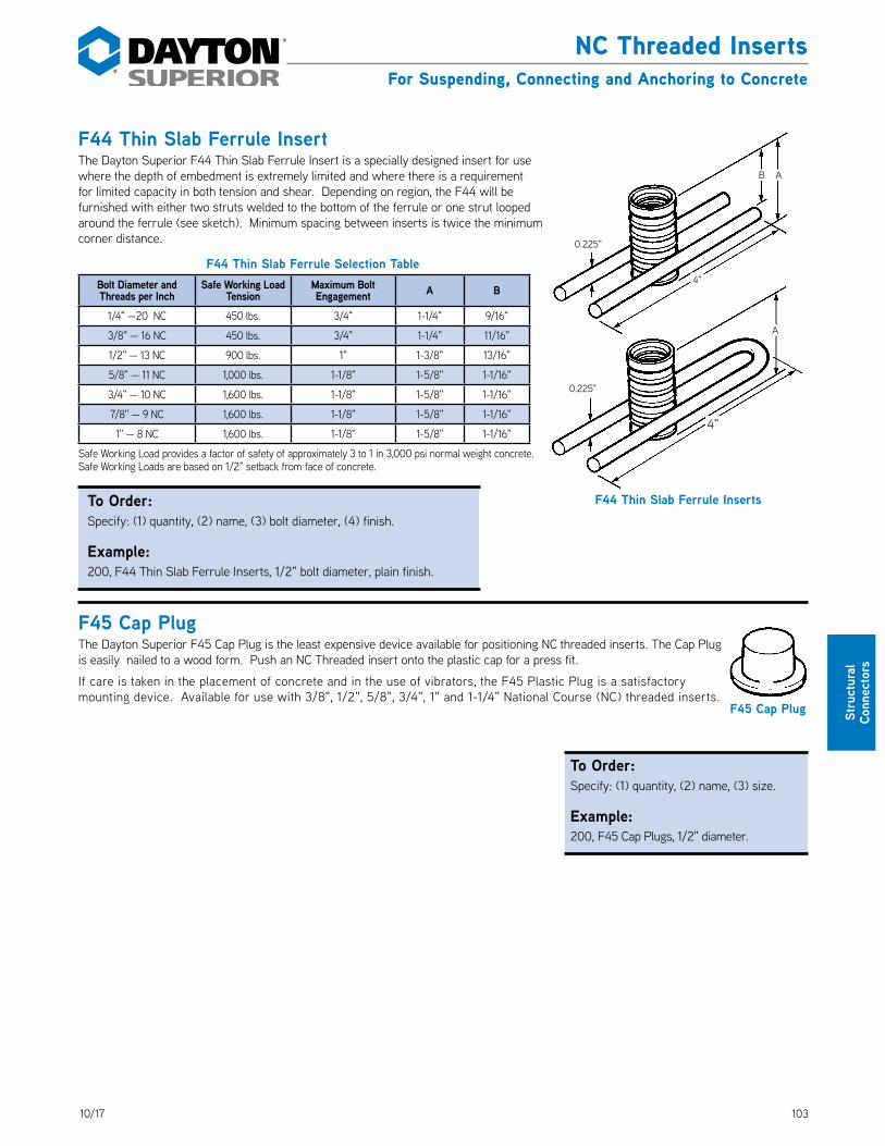
10310/17
Stru
ctur
al
Conn
ecto
rs
NC Threaded InsertsFor Suspending, Connecting and Anchoring to Concrete
F44 Thin Slab Ferrule InsertThe Dayton Superior F44 Thin Slab Ferrule Insert is a specially designed insert for use where the depth of embedment is extremely limited and where there is a requirement for limited capacity in both tension and shear. Depending on region, the F44 will be furnished with either two struts welded to the bottom of the ferrule or one strut looped around the ferrule (see sketch). Minimum spacing between inserts is twice the minimum corner distance. DS_F44
F44 Thin Slab Ferrule Selection TableBolt Diameter and Threads per Inch
Safe Working Load Tension
Maximum Bolt Engagement A B
1/4" —20 NC 450 lbs. 3/4" 1-1/4" 9/16"
3/8" — 16 NC 450 lbs. 3/4" 1-1/4" 11/16"
1/2" — 13 NC 900 lbs. 1" 1-3/8" 13/16"
5/8" — 11 NC 1,000 lbs. 1-1/8" 1-5/8" 1-1/16"
3/4" — 10 NC 1,600 lbs. 1-1/8" 1-5/8" 1-1/16"
7/8" — 9 NC 1,600 lbs. 1-1/8" 1-5/8" 1-1/16"
1" — 8 NC 1,600 lbs. 1-1/8" 1-5/8" 1-1/16"
Safe Working Load provides a factor of safety of approximately 3 to 1 in 3,000 psi normal weight concrete.Safe Working Loads are based on 1/2" setback from face of concrete.
To Order:Specify: (1) quantity, (2) name, (3) bolt diameter, (4) finish.
Example:200, F44 Thin Slab Ferrule Inserts, 1/2" bolt diameter, plain finish.
F45 Cap PlugThe Dayton Superior F45 Cap Plug is the least expensive device available for positioning NC threaded inserts. The Cap Plug is easily nailed to a wood form. Push an NC Threaded insert onto the plastic cap for a press fit.
If care is taken in the placement of concrete and in the use of vibrators, the F45 Plastic Plug is a satisfactory mounting device. Available for use with 3/8", 1/2", 5/8", 3/4", 1" and 1-1/4" National Course (NC) threaded inserts. DS_F45 F45 Cap Plug
A
0.225"
4"
B A
4"
0.225"
F44 Thin Slab Ferrule Inserts
To Order:Specify: (1) quantity, (2) name, (3) size.
Example:200, F45 Cap Plugs, 1/2" diameter.

104 10/17
Structural Connectors
NC Threaded InsertsFor Suspending, Connecting and Anchoring to Concrete
F50 Rocket/Kohler® Ferrule InsertThe Dayton Superior F50 Rocket Kohler Ferrule Insert is a two-strut ferrule insert with an extended length ferrule and integral washer face. The F50 insert is available in diameters from 1/4" through 1-1/4" and is well suited for structural connections or supporting hung ceilings, equipment, piping, etc. DS_F50
To Order:Specify: (1) quantity, (2) name, (3) bolt diameter, (4) finish.
Example:200, F50 Rocket/Kohler Ferrule Insert, 1/2" bolt diameter, plain finish.
F50 Rocket/Kohler Ferrule Insert Selection TableBolt Diameter and Threads
Per InchInsert Length
Minimum Edge
Distance
Minimum Corner
DistanceSafe Working Load Tension
Safe Working Load Shear A B Maximum Bolt
Engagement
1/4" – 20 NC 1-3/4" 4" 6" 750 lbs. 750 lbs. 1-3/4" 0.225" 1-1/4"
3/8" – 16 NC 1-3/4" 4" 6" 1,050 lbs. 1,350 lbs. 1-3/4" 0.225" 1-1/4"
1/2" – 13 NC 2-1/4" 6" 9" 1,575 lbs. 1,075 lbs. 2-1/4" 0.225" 1-3/4"
5/8" – 11 NC 3-3/8" 6" 11" 3,000 lbs. 3,000 lbs. 3-3/8" 0.312" 2-3/4"
3/4" – 10 NC 3-3/8" 6" 11" 3,000 lbs. 3,000 lbs. 3-3/8" 0.312" 2-3/4"
7/8" – 9 NC 3-3/4" 7" 12" 3,800 lbs. 3,800 lbs. 3-3/4" 0.340" 3-1/8"
1" – 8 NC 3-3/4" 7" 12" 3,800 lbs. 3,800 lbs. 3-3/4" 0.340" 3-1/8"
1-1/8" – 7 NC 4-1/4" 8" 14" 4,350 lbs. 4,350 lbs. 4-1/4" 0.340" 3-5/8"
1-1/4" – 7 NC 4-1/4" 8" 14" 4,350 lbs. 4,350 lbs. 4-1/4" 0.340" 3-5/8"
Safe Working Load provides a factor of safety of approximately 3 to 1 in 3,000 psi normal weight concrete.Safe Working Loads are based on 1/2" setback from face of concrete.
F52 Thin Slab Ferrule InsertThe Dayton Superior F52 Thin Slab Ferrule Insert is fabricated with four L-shaped struts resistance-welded to an NC thread ferrule. The F52 insert is available in 3/4" and 1" bolt diameters and in any height. DS_F52
To Order:Specify: (1) quantity, (2) name, (3) bolt diameter, (4) insert height, (5) finish.
Example:200, F52 Thin Slab Ferrule Insert, 1" bolt diameter, 5-1/2" height, plain finish.
F52 Thin Slab Ferrule Insert Selection TableBolt Diameter and Threads
Per InchInsert Length
Minimum Edge
Distance
Minimum Corner
DistanceSafe Working Load Tension
Safe Working Load Shear A B C D Maximum Bolt
Engagement
3/4" – 10 NC 3-1/8" 8" 12" 3,680 lbs. 3,200 lbs. 3-1/8" 3" 7" 0.306" 1-1/8"
1" – 8 NC 4-1/8" 12" 18" 5,300 lbs. 5,300 lbs. 4-1/8" 4" 9-3/8" 0.306" 1-1/8"
Safe Working Load provides a factor of safety of approximately 3 to 1 in 3,000 psi normal weight concrete.
D
1/8"
B
15°
A
CB
F52 Thin Slab Ferrule Insert
Length
AB
F50 Rocket/Kohler Ferrule Insert

10510/17
Stru
ctur
al
Conn
ecto
rs
NC Threaded InsertsFor Suspending, Connecting and Anchoring to Concrete
F54 Ductile Embed InsertThe Dayton Superior F54 Ductile Embed Insert is a one-piece, integrally hot forged unit fabricated out of smooth, round steel meeting ASTM A-29 Hot Rolled Grade 1045 requirements. DS_F54
Insert top has a round washer face with four nail holes. The user can nail or bolt the insert to side forms or wet set in face of panel as required. The bottom end has a forged, washer-face hex foot to resist pullout from the concrete.
Use as a cast-in-place insert or in a core and grout insert application. Several inserts can be laced and/or templated together to provide preset anchorage patterns for closely-spaced multiple insert requirements.
Longer insert lengths are available when required. Minimum spacing between the inserts, shown in the chart, is twice the minimum corner distance.
Available plain, electro-galvanized, hot-dipped galvanized or epoxy coated as required.
F54 Ductile Embed Insert Selection TableBolt Diameter
and Threads per Inch
Shaft Diameter
Insert Length
Safe Working Load Tension
Safe Working Load Shear
Minimum Edge Distance
Minimum Corner Distance
Flange Diameter “A”
Maximum Bolt Engagement
5/8" – 11 NC 3/4" 7-1/2"6,700 lbs. 4,310 lbs. 7-1/2" 15"
2" 15/16"9,030 lbs. 5,420 lbs. 10" 18"
3/4" – 10 NC 7/8" 9"8,800 lbs. 5,890 lbs. 9" 18"
2-1/4" 1-1/8"13,360 lbs. 8,020 lbs. 14" 20"
7/8" – 9 NC 1" 10-1/2"11,150 lbs. 8,050 lbs. 10-1/2" 18"
2-3/8" 1-5/16"18,350 lbs. 11,090 lbs. 16" 24"
1" – 8 NC 1-1/8" 12"13,790 lbs. 10,160 lbs. 12" 24"
2-1/2" 1-1/2"22,980 lbs. 14,540 lbs. 18" 30"
1-1/4" – 7 NC 1-3/8" 15"19,960 lbs. 15,570 lbs. 15" 30"
3-1/4" 1-7/8"33,150 lbs. 20,340 lbs. 24" 36"
Safe Working Loads provide a factor of safety of approximately 3 to 1 in 3,000 psi normal weight concrete.Safe Working Loads are based on 1/2" setback from the face of concrete.Minimum spacing between inserts is twice the corner distance.Note: Bolt diameter is 1/8" less shaft diameter all products.
Nail Running Nut
Setting BoltForm
Shaft Dia.
A
F54 Ductile Embed Insert
Length
To Order:Specify: (1) quantity, (2) name, (3) thread diameter, (4) overall length.
Example:550, F54 Ductile Embed Insert, 3/4" x 9" long.

106 10/17
Structural Connectors
NC Threaded InsertsFor Suspending, Connecting and Anchoring to Concrete
F57 Expanded Coil Ferrule InsertF59 Expanded Coil Ferrule InsertF61 Expanded Coil Ferrule InsertThe Dayton Superior Expanded Coil Ferrule Inserts were developed as a more effective means for increasing the insert’s tensile capacity, without increasing its depth of embedment. By increasing the width of the base, the volume of the resisting shear cone is significantly increased. The expanded pitch coils welded to the more deeply embedded end of the insert serve to distribute the applied loads over a larger volume of concrete. DS_F57 DS_F59 DS_F61Available in longer lengths, as required. Minimum spacing between inserts is twice the corner spacing.
Expanded Coil Ferrule Loop Insert Selection Table
Insert Type
Bolt Diameter and Threads per
InchInsert Length
Minimum Edge
Distance
Minimum Corner
DistanceSafe Working Load Tension
Safe Working Load Shear A B C D Maximum Bolt
Engagement
F57 3/4" – 10 NC 4-5/8"6" 9" 4,650 lbs. 2,730 lbs.
4-5/8" 2-1/8" 1-1/2" 0.375" 1-1/8"14" 20" 5,890 lbs. 5,890 lbs.
F57 1" – 8 NC 5-5/8"8" 12" 6,990 lbs. 4,300 lbs.
5-5/8" 2-3/4" 2-1/4" 0.440" 1-1/8"16" 24" 8,100 lbs. 8,100 lbs.
F59 1" – 8 NC 5-5/8"8" 12" 7,465 lbs. 5,200 lbs.
5-5/8" 2-3/4" 2-1/4" 0.440" 1-1/8"18" 26" 13,310 lbs. 13,310 lbs.
F59 1-1/4" – 7 NC 7-5/8"10" 15" 9,920 lbs. 7,940 lbs.
7-5/8" 3" 2-3/4" 0.440" 1-3/4"18" 26" 13,310 lbs. 13,310 lbs.
F61 1-1/2" – 6 NC 9-5/8"12" 18" 13,180 lbs. 12,450 lbs.
9-5/8" 3-3/8" 3-5/8" 0.440" 2-1/4"22" 30" 18,680 lbs. 18,680 lbs.
Safe Working Load provides a factor of safety of approximately 3 to 1 in 3,000 psi normal weight concrete.Safe Working Loads are based on insert 1/2" setback from the face of concrete.Minimum spacing between inserts is twice the corner.
C
B
A
D
F57 Insert – 2 StrutsF59 Insert – 4 StrutsF61 Insert – 6 Struts
To Order:Specify: (1) quantity, (2) name, (3) bolt diameter, (4) finish.
Example:200, F61 Expanded Coil Ferrule Inserts, 1-1/2" dia., plain finish.
Rev. 01/16
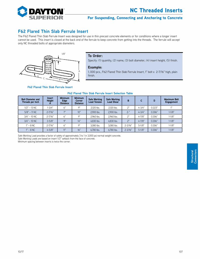
10710/17
Stru
ctur
al
Conn
ecto
rs
NC Threaded InsertsFor Suspending, Connecting and Anchoring to Concrete
F62 Flared Thin Slab Ferrule InsertThe F62 Flared Thin Slab Ferrule Insert was designed for use in thin precast concrete elements or for conditions where a longer insert cannot be used. This insert is closed at the back end of the ferrule to keep concrete from getting into the threads. The ferrule will accept only NC threaded bolts of appropriate diameters. DS_F62
F62 Flared Thin Slab Ferrule Insert Selection Table
Bolt Diameter and Threads per Inch
Insert Height
A
Minimum Edge
Distance
Minimum Corner
DistanceSafe Working Load Tension
Safe Working Load Shear B C D Maximum Bolt
Engagement
1/2" – 13 NC 1-3/4" 6" 9" 2,120 lbs. 2,120 lbs. 2" 4-3/4" 0.223" 1"
5/8" – 11 NC 2-7/16" 7" 10" 2,900 lbs. 2,900 lbs. 2-" 4-3/4" 0.306" 1-1/8"
3/4" – 10 NC 2-7/16" 6" 9" 2,960 lbs. 2,960 lbs. 2" 4-7/8" 0.306" 1-1/8"
3/4" – 10 NC 3-5/8" 9" 14" 4,830 lbs. 4,830 lbs. 2" 4-7/8" 0.306" 1-1/8"
1" – 8 NC 2-7/16" 6" 9" 3,080 lbs. 3,080 lbs. 2-3/16" 5-1/8" 0.306" 1-1/8"
1" – 8 NC 4-5/8" 11" 16" 6,780 lbs. 6,780 lbs. 2-3/16" 5-1/8" 0.306" 1-1/8"
Safe Working Load provides a factor of safety of approximately 3 to 1 in 3,000 psi normal weight concrete.Safe Working Loads are based on insert 1/2" setback from the face of concrete.Minimum spacing between inserts is twice the corner.
DC B
1/8"
A
F62 Flared Thin Slab Ferrule Insert
To Order:Specify: (1) quantity, (2) name, (3) bolt diameter, (4) insert height, (5) finish.
Example:1, 000 pcs., F62 Flared Thin Slab Ferrule Insert, 1" bolt x 2-7/16" high, plain finish.

108 10/17
Structural Connectors
NC Threaded InsertsFor Suspending, Connecting and Anchoring to Concrete
F64 Ferrule Loop InsertThe Dayton Superior F64 Ferrule Loop Insert is manufactured by welding a wire loop to a steel ferrule which has been machined from bar stock. One end of the ferrule is closed, while the other end is drilled and tapped to accept an NC threaded bolt. DS_F64
Typically, this insert is used to attach a precast wall panel to a building frame, as well as provide attachment of other structural elements that may be required.
Mounting Washer Option for all Ferrule Type InsertsAll ferrule type inserts are available with a 16 gauge x 2" x 2" mounting washer as an option. The mounting washer allows you to nail a ferrule type insert to the form.
To keep concrete from entering the threaded portion of an insert with mounting washer, cover the open face of the washer with duct tape.
F64 Ferrule Loop Insert Selection Table
Bolt Diameter and Threads per Inch
Insert Height (A)
Minimum Edge Distance
Minimum Corner
DistanceSafe Working Load
TensionSafe Working Load Shear B Maximum Bolt
Engagement
1/2" — 13 NC 4-1/8"5" 10" 3,000 lbs. 1,810 lbs.
0.223" 1"9" 15" 3,000 lbs. 3,000 lbs.
1/2" — 13 NC 6-1/8"7" 12" 5,000 lbs. 3,410 lbs.
0.306" 1"9" 12" 5,000 lbs. 3,410 lbs.
5/8" — 11 NC 4-1/8"5" 10" 3,000 lbs. 1,810 lbs.
0.223" 1-1/8"9" 12" 3,000 lbs. 3,000 lbs.
5/8" — 11 NC 6-1/8"7" 12" 5,000 lbs. 3,420 lbs.
0.306" 1-1/8"11" 15" 5,000 lbs. 5,000 lbs.
3/4" — 10 NC 4-1/8"5" 10" 3,000 lbs. 1,810 lbs.
0.223" 1-1/8"9" 12" 3,000 lbs. 3,000 lbs.
3/4" — 10 NC 6-1/8"7" 12" 5,000 lbs. 3,420 lbs.
0.306" 1-1/8"11" 15" 5,000 lbs. 5,000 lbs.
7/8" — 9 NC 6-1/8"7" 12" 5,000 lbs. 3,420 lbs.
0.306" 1-1/8"11" 15" 5,000 lbs. 5,000 lbs.
1" — 8 NC 6-1/8"7" 12" 5,000 lbs. 3,420 lbs.
0.306" 1-1/8"11" 12" 5,000 lbs. 4,650 lbs.
1" — 8 NC 8-1/8"7" 12" 5,000 lbs. 3,830 lbs.
0.306" 1-1/8"11" 15" 5,000 lbs. 5,000 lbs.
Safe Working Load provides a factor of safety of approximately 3 to 1 in 3,000 psi normal weight concrete.Safe Working Loads are based on 1/2" setback from the face of the concrete.Minimum spacing between inserts is twice the minimum corner distance.
A
1/8"
B
Insert with Optional Mounting Washer.
F64 Ferrule Loop Insert
To Order:Specify: (1) quantity, (2) name, (3) bolt diameter, (4) insert length, (5) finish.
Example:200, F64 Ferrule Loop Insert, 5/8" bolt diameter, 6-1/8" insert length, plain finish.

10910/17
Stru
ctur
al
Conn
ecto
rs
NC Threaded InsertsFor Suspending, Connecting and Anchoring to Concrete
F65LF Type LF Ferrule InsertThe Dayton Superior F65LF Ferrule Insert is designed for structural connections. Minimum spacing between inserts is twice the minimum corner distance.
Features• Open end ferrule available• Available in electro galvanized and stainless steel• Insert Length is 4.125"
F72 Threaded Setting PlugThe Dayton Superior F72 Threaded Setting Plugs eliminate the need for putting large holes in formwork in order to secure the inserts to the forms. Basically a socket set screw, it is drilled through and tapped with #8-32 thread. It can be nailed to wood forms, or bolted to steel forms using an #8-32 threaded bolt. The reusable plugs are easily removed using a standard hex wrench. DS_F72
F72 Selection Table
Bolt Diameter and Threads per InchDimensions
L W
3/8" – 16 NC 3/8" 3/16"
1/2" – 13 NC 3/8" 1/4"
5/8" – 11 NC 1/2" 5/16"
3/4" – 10 NC 5/8" 3/8"
1" – 8 NC 1" 9/16"
F74 Threaded Plastic PlugThe Dayton Superior F74 Threaded Plastic Plug is manufactured with National Course (NC) threads to fit 3/8", 1/2", 5/8", 3/4", 7/8" and 1" NC threaded inserts. A hole is provided through the plug that may be used to attach (nail) the plug to the form. DS_F74
W
L
Tapped Internally with #8-32 ThreadNail or
#8-#32 Screw
Dia.
F72 Threaded Setting Plug
F74 Threaded Plastic Plug
To Order:Specify: (1) quantity, (2) name, (3) diameter.
Example:200, F72 Threaded Setting Plugs, 3/4" diameter.
To Order:Specify: (1) quantity, (2) name, (3) bolt diameter.
Example:200, F74 Threaded Plastic Plugs, 3/4" diameter.
F65LF Ferrule Insert
F65LF Tyle LF Ferrule Insert Selection Table
Diameter Safe Working Load Tension
Safe Working Load Shear
1/2" 2,115 2,200
5/8" 2,715 2,390
3/4" 3,510 2,450
7/8" 3,510 2,560
1" 3,510 2,610

110 10/17
Structural Connectors
NC Threaded InsertsFor Suspending, Connecting and Anchoring to Concrete
P90 Connecting Systems Nylon Threaded InsertsDayton Superior P90 Connecting Systems Threaded Inserts are mineral-filled nylon inserts designed for attaching, suspending and fastening objects to precast concrete. They provide the precast manufacturer with an excellent, cost effective fastening system. DS_P90
Advantages:• Economical
• Light weight
• Easy to handle and use
• Available in five bolt diameters
• Can be used in hundreds of applications
Typical Applications:• Lifting insert for light loads
• Secure handles of burial vaults
• Secure mechanical equipment to concrete pads
• Secure telephone booths to concrete pads
• Fasten cable holders to utility poles
• Secure benches, picnic tables and other landscape items to concrete bases
• Suspend pipes, conduits and other utilities from concrete panels and ceilings
• Plus many, many others
Bolt Diameter and Threads per Inch
Insert Length
AB C
Minimum Edge
Distance
Minimum Corner
DistanceSafe Working Load Tension
Safe Working Load Shear
1/4" - 20 NC 1-1/2" 1" 3/4" 3" 6" 1272 763
3/8" - 16 NC 1-1/2" 1" 3/4" 3" 6" 1299 1251
1/2" - 13 NC 1-5/8" 1-3/8" 3/4" 3-1/2" 7" 1465 1465
1/2" -13 NC 2-5/8" 1-3/8" 3/4" 5-1/2" 11" 3007 3406
5/8" - 11 NC 3" 1-1/2" 7/8" 6" 12" 3674 4365
3/4" - 10 NC 3-1/4" 1-5/8" 1" 6-1/2" 13" 4143 4922
3:1 SF @ 5000 psi Concrete
C
A
B
Steel Installation Using Bolt
BoltP90
Steel Form

11110/17
Stru
ctur
al
Conn
ecto
rs
NC Threaded InsertsFor Suspending, Connecting and Anchoring to Concrete
D108A Headed Dowel Bar InsertThe Dayton Superior D108A Dowel Bar Insert is a one-piece unit integrally forged from material meeting ASTM A-615 Grade 60 requirements. This insert works extremely well in areas of heavy rebar congestion and provides excellent anchorage provisions for light standards, signs, posts, fixtures, etc. The D108A Headed Dowel Bar Insert is approved by the International Code Council, evaluation report ICC #4028. DS_108
The top of the insert has a round washer face with four nail holes. Nail or bolt insert to side forms or wet set in face of panel as required. The bottom end has a hot-forged, washer face hex foot to resist pull-out from the concrete.
Use this versatile insert as a cast-in-place insert or in a core and grout application. Lace and/or template several inserts together to provide repeat anchorage patterns of two, three, four or more inserts.
Longer length inserts are available as required. Minimum spacing between the inserts shown in the chart is twice the minimum corner distance.
Available plain, electro-galvanized, hot-dipped galvanized or epoxy coated as required.
D108A Headed Dowel Bar Insert Selection TableBolt Diameter and Threads
per InchShaft Diameter Insert Length Safe Working
Load TensionSafe Working Load Shear
Minimum Edge Distance
Minimum Corner
Distance
Flange Diameter
“A”Maximum Bolt Engagement
5/8" – 11 NC #4 7-1/2" 6,000 lbs. 4,000 lbs. 8" 12" 1-7/8" 7/8"
3/4" – 10 NC #5 9" 9,300 lbs. 6,200 lbs. 11" 15" 2" 1"
7/8" – 9 NC #6 10-1/2" 13,200 lbs. 8,800 lbs. 13" 20" 2-1/4" 1-1/8"
1" – 8 NC #7 12" 18,000 lbs. 12,000 lbs. 16" 24" 2-7/16" 1-1/4"
Safe Working Load provides a factor of safety of approximately 3 to 1 in 3,000 psi normal weight concrete as calculated from criteria in ACI 318. Specific applications are the responsibility of the Engineer of Record, not Dayton Superior.
Minimum spacing between inserts is twice the corner distance.Insert Length to bottom of bolt head.
A
D108A Headed Dowel Bar Insert
Length
Laced and Template Application
Core and Grout Application
To Order:Specify: (1) quantity, (2) name, (3) bar size, (4) overall length, (5) finish.
Example:300, D108A Headed Dowel Bar Insert, #5 x 7-1/2" long, plain finish.

112 10/17
Notes and Sketches
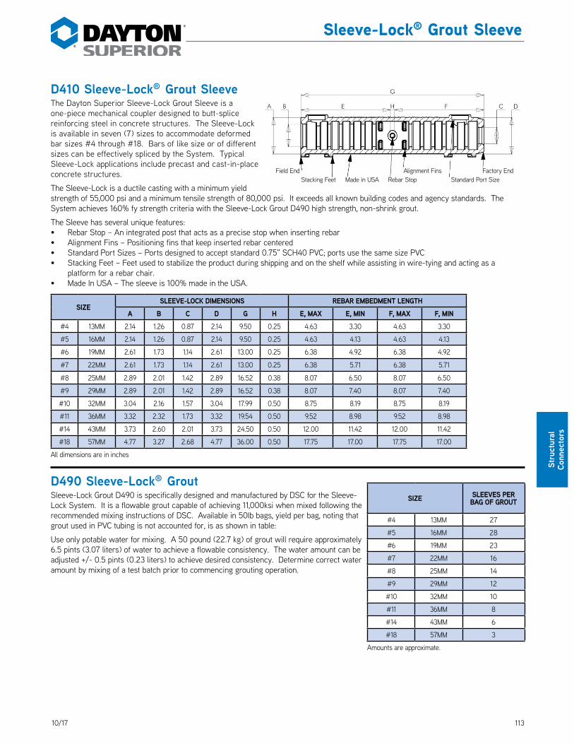
11310/17
Stru
ctur
al
Conn
ecto
rs
Sleeve-Lock® Grout Sleeve
D410 Sleeve-Lock® Grout SleeveThe Dayton Superior Sleeve-Lock Grout Sleeve is a one-piece mechanical coupler designed to butt-splice reinforcing steel in concrete structures. The Sleeve-Lock is available in seven (7) sizes to accommodate deformed bar sizes #4 through #18. Bars of like size or of different sizes can be effectively spliced by the System. Typical Sleeve-Lock applications include precast and cast-in-place concrete structures. DS_410
The Sleeve-Lock is a ductile casting with a minimum yield strength of 55,000 psi and a minimum tensile strength of 80,000 psi. It exceeds all known building codes and agency standards. The System achieves 160% fy strength criteria with the Sleeve-Lock Grout D490 high strength, non-shrink grout.
The Sleeve has several unique features:• Rebar Stop – An integrated post that acts as a precise stop when inserting rebar• Alignment Fins – Positioning fins that keep inserted rebar centered• Standard Port Sizes – Ports designed to accept standard 0.75" SCH40 PVC; ports use the same size PVC• Stacking Feet – Feet used to stabilize the product during shipping and on the shelf while assisting in wire-tying and acting as a
platform for a rebar chair.• Made In USA – The sleeve is 100% made in the USA.
SIZESLEEVE-LOCK DIMENSIONS REBAR EMBEDMENT LENGTH
A B C D G H E, MAX E, MIN F, MAX F, MIN#4 13MM 2.14 1.26 0.87 2.14 9.50 0.25 4.63 3.30 4.63 3.30
#5 16MM 2.14 1.26 0.87 2.14 9.50 0.25 4.63 4.13 4.63 4.13
#6 19MM 2.61 1.73 1.14 2.61 13.00 0.25 6.38 4.92 6.38 4.92
#7 22MM 2.61 1.73 1.14 2.61 13.00 0.25 6.38 5.71 6.38 5.71
#8 25MM 2.89 2.01 1.42 2.89 16.52 0.38 8.07 6.50 8.07 6.50
#9 29MM 2.89 2.01 1.42 2.89 16.52 0.38 8.07 7.40 8.07 7.40
#10 32MM 3.04 2.16 1.57 3.04 17.99 0.50 8.75 8.19 8.75 8.19
#11 36MM 3.32 2.32 1.73 3.32 19.54 0.50 9.52 8.98 9.52 8.98
#14 43MM 3.73 2.60 2.01 3.73 24.50 0.50 12.00 11.42 12.00 11.42
#18 57MM 4.77 3.27 2.68 4.77 36.00 0.50 17.75 17.00 17.75 17.00
All dimensions are in inches
D490 Sleeve-Lock® GroutSleeve-Lock Grout D490 is specifically designed and manufactured by DSC for the Sleeve-Lock System. It is a flowable grout capable of achieving 11,000ksi when mixed following the recommended mixing instructions of DSC. Available in 50lb bags, yield per bag, noting that grout used in PVC tubing is not accounted for, is as shown in table: DS_490
Use only potable water for mixing. A 50 pound (22.7 kg) of grout will require approximately 6.5 pints (3.07 liters) of water to achieve a flowable consistency. The water amount can be adjusted +/- 0.5 pints (0.23 liters) to achieve desired consistency. Determine correct water amount by mixing of a test batch prior to commencing grouting operation.
SIZE SLEEVES PER BAG OF GROUT
#4 13MM 27
#5 16MM 28
#6 19MM 23
#7 22MM 16
#8 25MM 14
#9 29MM 12
#10 32MM 10
#11 36MM 8
#14 43MM 6
#18 57MM 3
Amounts are approximate.
Standard Port SizeFactory EndAlignment Fins
Rebar StopMade in USAStacking FeetField End

114 10/17
Structural Connectors
Sleeve-Lock® Grout Sleeve
D487 Sleeve-Lock® Seal PlugThe Sleeve-Lock Seal Plug is a rubberized plug used to seal the connection between the Sleeve-Lock Grout Sleeve and the reinforcing bar. It is designed to keep concrete from entering the inner cavity of the Sleeve-Lock Grout Sleeve on the Factory End and to contain the pumped in grout on the Field End. Per size, the Sleeve-Lock Seal Plug can be used on either end meaning that only one size Sleeve-Lock Seal Plug (QTY 2) per sleeve need be stocked. DS_487
D491 Sleeve-Lock® Form PlugThe Sleeve-Lock Form Plug is a device using a rubberized grommet and a clamping device and used to attach the Sleeve-Lock Grout Sleeve to a piece of formwork i.e. steel, lumber, composite. It is designed to fasten the sleeve to the formwork while keeping concrete out of the sleeve’s inner chamber. It is to be used on the Field End only and is not designed to be used as a structural connection. DS_491
D492 Sleeve-Lock® ¾" SCH40 PVCThe Sleeve-Lock ¾" SCH40 PVC is standard, off the shelf, PVC, used to fill the inner chamber of the Sleeve-Lock Grout Sleeve. Either port of the sleeve uses the same size PVC. It is available locally or through DSC. DS_492
D493 Sleeve-Lock® Port PlugThe Sleeve-Lock Port Plug is a plastic plug used during jobsite shipping to plug the ports in order to keep debris from entering the inner chamber of the sleeve. They can also be used to plug the PVC before or after grouting. One size will fit either end port or PVC. DS_492
How to Specify:Specific: Mechanical splices shall be the Sleeve-Lock® Grout Sleeve System manufactured by Dayton Superior Corporation.
Generic: The mechanical connection shall meet building code requirements of developing in tension and compression, as required, by local standards and codes. Grouting must be performed in accordance with the manufacturer's recommended grouting procedures.
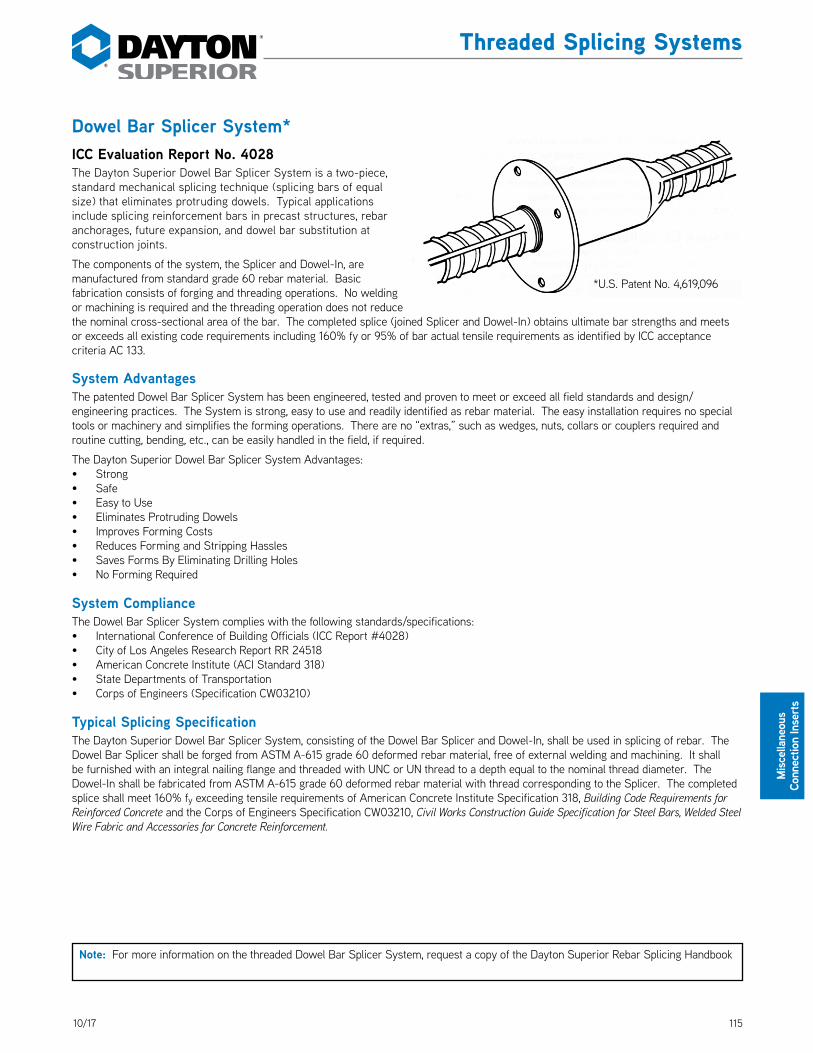
11510/17
Misc
ellan
eous
Co
nnec
tion
Inse
rts
Dowel Bar Splicer System*ICC Evaluation Report No. 4028The Dayton Superior Dowel Bar Splicer System is a two-piece, standard mechanical splicing technique (splicing bars of equal size) that eliminates protruding dowels. Typical applications include splicing reinforcement bars in precast structures, rebar anchorages, future expansion, and dowel bar substitution at construction joints. DS_DowelBarSplicer
The components of the system, the Splicer and Dowel-In, are manufactured from standard grade 60 rebar material. Basic fabrication consists of forging and threading operations. No welding or machining is required and the threading operation does not reduce the nominal cross-sectional area of the bar. The completed splice (joined Splicer and Dowel-In) obtains ultimate bar strengths and meets or exceeds all existing code requirements including 160% fy or 95% of bar actual tensile requirements as identified by ICC acceptance criteria AC 133.
System AdvantagesThe patented Dowel Bar Splicer System has been engineered, tested and proven to meet or exceed all field standards and design/engineering practices. The System is strong, easy to use and readily identified as rebar material. The easy installation requires no special tools or machinery and simplifies the forming operations. There are no “extras,” such as wedges, nuts, collars or couplers required and routine cutting, bending, etc., can be easily handled in the field, if required.
The Dayton Superior Dowel Bar Splicer System Advantages:• Strong• Safe• Easy to Use• Eliminates Protruding Dowels• Improves Forming Costs• Reduces Forming and Stripping Hassles• Saves Forms By Eliminating Drilling Holes• No Forming Required
System ComplianceThe Dowel Bar Splicer System complies with the following standards/specifications:• International Conference of Building Officials (ICC Report #4028)• City of Los Angeles Research Report RR 24518• American Concrete Institute (ACI Standard 318)• State Departments of Transportation• Corps of Engineers (Specification CW03210)
Typical Splicing SpecificationThe Dayton Superior Dowel Bar Splicer System, consisting of the Dowel Bar Splicer and Dowel-In, shall be used in splicing of rebar. The Dowel Bar Splicer shall be forged from ASTM A-615 grade 60 deformed rebar material, free of external welding and machining. It shall be furnished with an integral nailing flange and threaded with UNC or UN thread to a depth equal to the nominal thread diameter. The Dowel-In shall be fabricated from ASTM A-615 grade 60 deformed rebar material with thread corresponding to the Splicer. The completed splice shall meet 160% fy exceeding tensile requirements of American Concrete Institute Specification 318, Building Code Requirements for Reinforced Concrete and the Corps of Engineers Specification CW03210, Civil Works Construction Guide Specification for Steel Bars, Welded Steel Wire Fabric and Accessories for Concrete Reinforcement.
Note: For more information on the threaded Dowel Bar Splicer System, request a copy of the Dayton Superior Rebar Splicing Handbook
*U.S. Patent No. 4,619,096
Threaded Splicing Systems

116 10/17
Miscellaneous
Connection Inserts
Dayton Superior Bar Lock® Coupler System*ICC Evaluation Report No. 5064The Dayton Superior Bar-Lock Coupler System provides a simple, quick, cost effective method for splicing rebar in tension and/or compression applications. Bar-Lock couplers may be used with plain or deformed bars in sizes #4 through #18.
Bar Lock couplers utilize lock-shear bolts and special grip rails to mechanically splice with the rebar. The serrated grip rails cradle the rebar and are embedded in the rebar as the lock-shear bolts are tightened. The heads of the lock-shear bolts are designed to shear off at a prescribed torque in order to accomplish proper installation. DS_BarLockCoupler
System Advantages:• Quick and easy to install – saves time and money.• Eliminates bar threading and/or special bar end treatment.• No special installation equipment required.• High strength in tension, compression and seismic applications.• Available in standard, transition and weldable versions in #4 through #18 sizes.• Ideal for new construction and rehab projects.
System ComplianceBar-Lock couplers are test-certified to exceed the requirements of, are pre-qualified and approved, or recognized by the following building approval agencies:
• State Departments of Transportation• International Conference of Building Officials (ICC)• Building Officials and Code Administrators (BOCA)• Southern Building Code Congress International (SBCCI)• American Concrete Institute (ACI)• Concrete Reinforcing Steel Institute (CRSI)• City of Los Angeles Department of Building and
SafetyBar-Lock coupler source material is fabricated under ISO9000 quality standards. Bar-Lock couplers are tested by independent, certified testing laboratories in four modes of testing: tension, compression, fatigue and cyclic. All tests are done to the requirements of ICC and/or Caltrans requirements utilizing ASTM A615 grade 60 rebar material. Copies of test reports are available on request.
Typical Specification
By specific name: Bar Lock Mechanical Coupler System manufactured by Dayton Superior Concrete Accessories.
By generic description: Mechanical butt splices utilizing lock-shear bolts and internal serrated grip rails within the coupling sleeve. They shall exceed the
specification requirements for both tension and compression specified by ACI 318 and the Uniform Building code, and be recognized by the International Conference of Building Officials (ICC).
Bar Lock® Rebar Coupler System
Typical Bar-Lock Coupler System Splice
*U.S. Patent No. 4,666,326 and 5,046,878
Note: For more information on the Bar Lock Coupler System, request a copy of the Dayton Superior Rebar Splicing Handbook

11710/17
Misc
ellan
eous
Co
nnec
tion
Inse
rts
F11 Hanger Insert and F12 Hanger HookOne of the more economical and effective devices for providing points of anchorage for suspended ceilings is the hanger insert that can be fastened to a beam soffit by nailing or taping. The metal shell provides a cavity and the wire clip provides the anchorage for the attachment of ceiling suspension wires. If preferred, the Hanger Hook provides a simple method for the attachment of perforated metal hanger straps that can be used for the support of pipe, conduit, etc. Both insert and hook are fabricated from galvanized material. The F12 Hanger Hook is available with 9/32" or 13/32" holes. DS_F11_F12
To Order:Specify: (1) quantity, (2) name, (3) hole size in F12.
Example:200 each, F11 Hanger Inserts and F12 Hanger Hooks, 9/23" holes.
P30 Corewall® Nut Type Slotted InsertP31 Corewall® Strap Type Slotted InsertCOREWALL Slotted Inserts and accessories are engineered for performance and have proven to be one of the most advanced, adjustable inserts available on the market today. The slotted inserts feature a plastic back and a removable plastic slot cover that keeps the insert clean and saves you valuable time during the erection process.
COREWALL slotted inserts from Dayton Superior are available in two different types, the P30 Nut Type Slotted Insert and the P31 Strap Type Slotted Insert. Both types have tabs on each end of the insert for easy attachment to your forms.
The P30 Nut Type Slotted Insert uses a spring loaded, zinc-plated, heavy duty 3/4"-10 National Course (NC) threaded nut to provide fast, efficient and reliable connections. The P31 Strap Type Slotted Insert is used with either the P32 Standard Strap Anchor or the P33 Slotted Strap Anchor, depending upon your erection requirements. The P34 Threaded Strap Anchor is used with the P30 Nut Type Slotted Insert.
The design of the strap anchor allows for fast installation of the anchor into the slotted insert. This speeds up the erection process and saves valuable installation time. As part of the erection process, the strap anchor is welded to the building’s structural frame to make a ductile connection. All COREWALL products are manufactured from a weldable grade of steel.
Dayton Superior COREWALL slotted inserts are ideal for use in precast concrete industrial wall panels, architectural panels, structural panels or precast parking structures. The COREWALL slotted inserts are also suitable for use in seismic areas.
F11 Hanger Insert F12 Hanger Hook
Other Connection Inserts
P31 Strap Type Slotted Insert
Fast, High Strength, Reliable Concrete Connection Inserts
P30 Nut Type Slotted Insert

118 10/17
Miscellaneous
Connection Inserts
Other Connection Inserts
P30 Corewall® Nut Type Slotted InsertThe Dayton Superior P30 Nut Type Slotted Insert uses a spring loaded, zinc plated, heavy duty 3/4"-10 NC threaded nut to provide fast, efficient and reliable connections. The P30 insert can be used with standard NC threaded bolts or a P34 Threaded Strap Anchor, if a welded connection is required. P30 inserts are available in 4", 6" and 8" standard lengths with either blue epoxy-polyester or hot dipped galvanized (HDG) finish. Type 304 or 316 stainless steel is available on request. DS_P30
P30 Corewall Nut Type Slotted Insert Selection Table
Product Code Tension Safe Working Load
Shear Safe Working Load A B C D Adjustment
ECS425 4,000 lbs. 6,650 lbs. 4" 3-3/16" 2-1/2" 5-1/2" 2-1/2"
CS625 4,000 lbs. 6,650 lbs. 6" 3-3/16" 2-1/2" 7-1/2" 4-1/2"
CS825 4,000 lbs. 6,650 lbs. 8" 3-3/16" 2-1/2" 9-1/2" 6-1/2"
CS435 5,350 lbs. 6,650 lbs. 4" 3-3/8" 3-1/2" 5-1/2" 2-1/2"
CS635 5,350 lbs. 6,650 lbs. 6" 3-3/8" 3-1/2" 7-1/2" 4-1/2"
CS835 5,350 lbs. 6,650 lbs. 8" 3-3/8" 3-1/2" 9-1/2" 6-1/2"
CS445 6,650 lbs. 6,650 lbs. 4" 3-11/16" 4-1/2" 5-1/2" 2-1/2"
CS645 6,650 lbs. 6,650 lbs. 6" 3-11/16" 4-1/2" 7-1/2" 4-1/2"
CS845 6,650 lbs. 6,650 lbs. 8" 3-11/16" 4-1/2" 9-1/2" 6-1/2"
Safe Working Loads provide a factor of safety of approximately 3 to 1 in 5,000 psi normal weight concrete.
For proper connection to the structural frame of the building, use either a 3/4"-10 NC threaded bolt or rod meeting ASTM A-325 or SAE Grade 5 Standards.
P30 Corewall Slotted Insert Nut Type
B
AD
C
E
13/16"
To Order:Specify: (1) quantity, (2) name, (3) part number, (4) finish.
Example:200, P30 Corewall Nut Type Slotted Inserts, #CS425, hot-dip galvanized.
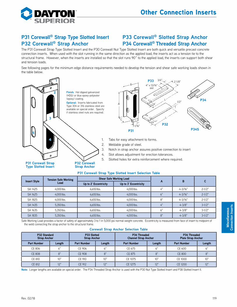
11910/17
Misc
ellan
eous
Co
nnec
tion
Inse
rts
Other Connection Inserts
P31 Corewall® Strap Type Slotted InsertP32 Corewall® Strap AnchorThe P31 Corewall Strap Type Slotted Insert and the P30 Corewall Nut Type Slotted Insert are both quick and versatile precast concrete connection inserts. When used with the slot running in the same direction as the applied load, the inserts act as a tension tie to the structural frame. However, when the inserts are installed so that the slot runs 90˚ to the applied load, the inserts can support both shear and tension loads. DS_P31 DS_P32 DS_P33 DS_P34
See following pages for the minimum edge distance requirements needed to develop the tension and shear safe working loads shown in the table below.
P31 Corewall Strap Type Slotted Insert Selection Table
Insert Style Tension Safe Working Load
Shear Safe Working LoadA B C
Up to 2' Eccentricity Up to 3' EccentricitySA 1425 4,000 lbs. 6,650 lbs. 4,000 lbs. 4" 4-3/16" 2-1/2"
SA 1625 4,000 lbs. 6,650 lbs. 4,000 lbs. 6" 4-3/16" 2-1/2"
SA 1825 4,000 lbs. 6,650 lbs. 4,000 lbs. 8" 4-3/16" 2-1/2"
SA 1435 5,350 lbs. 6,650 lbs. 4,000 lbs. 4" 4-3/8" 3-1/2"
SA 1635 5,350 lbs. 6,650 lbs. 4,000 lbs. 6" 4-3/8" 3-1/2"
SA 1835 5,350 lbs. 6,650 lbs. 4,000 lbs. 8" 4-3/8" 3-1/2"
Safe Working Load provides a factor of safety of approximately 3 to 1 in 5,000 psi normal weight concrete. Eccentricity is measured from face of insert to midpoint of the weld connecting the strap anchor to the structural frame.
Corewall Strap Anchor Selection TableP32 StandardStrap Anchor
P33 SlottedStrap Anchor
P34 ThreadedChannel Strap Anchor
P34 ThreadedPlate Strap Anchor
Part Number Length Part Number Length Part Number Length Part Number LengthCE 806 6" CE 906 6" CE 675 6" CE 600 6"
CE 808 8" CE 908 8" CE 875 8" CE 800 8"
CE 810 10" CE 910 10" CE 1075 10" CE 1000 10"
CE 812 12" CE 912 12" CE 1275 12" CE 1200 12"
Note: Longer lengths are available on special order. The P34 Threaded Strap Anchor is used with the P30 Nut Type Slotted Insert and P38 Slotted Insert II.
P33 Corewall® Slotted Strap AnchorP34 Corewall® Threaded Strap Anchor
P31
P34
P32
P33B
A
L
L
C
1-1/16"
4" x 13/16" slot
2 1/8"
1-1/4"
1-1/4"
1/2"
3/4"
Finish: Hot dipped galvanized (HDG) or blue epoxy-polyester (epoxy) coating.Optional: Inserts fabricated from Type 304 or 316 stainless steel are available on special order. Specify if stainless steel nuts are required.
P31 Corewall Strap Type Slotted Insert
P32 Corewall Strap Anchor
1
2
3
4
5
1. Tabs for easy attachment to forms.2. Weldable grade of steel.3. Notch in strap anchor assures positive connection to insert4. Slot allows adjustment for erection tolerances.5. Slotted holes for extra reinforcement where required.
P34S
Rev. 02/18
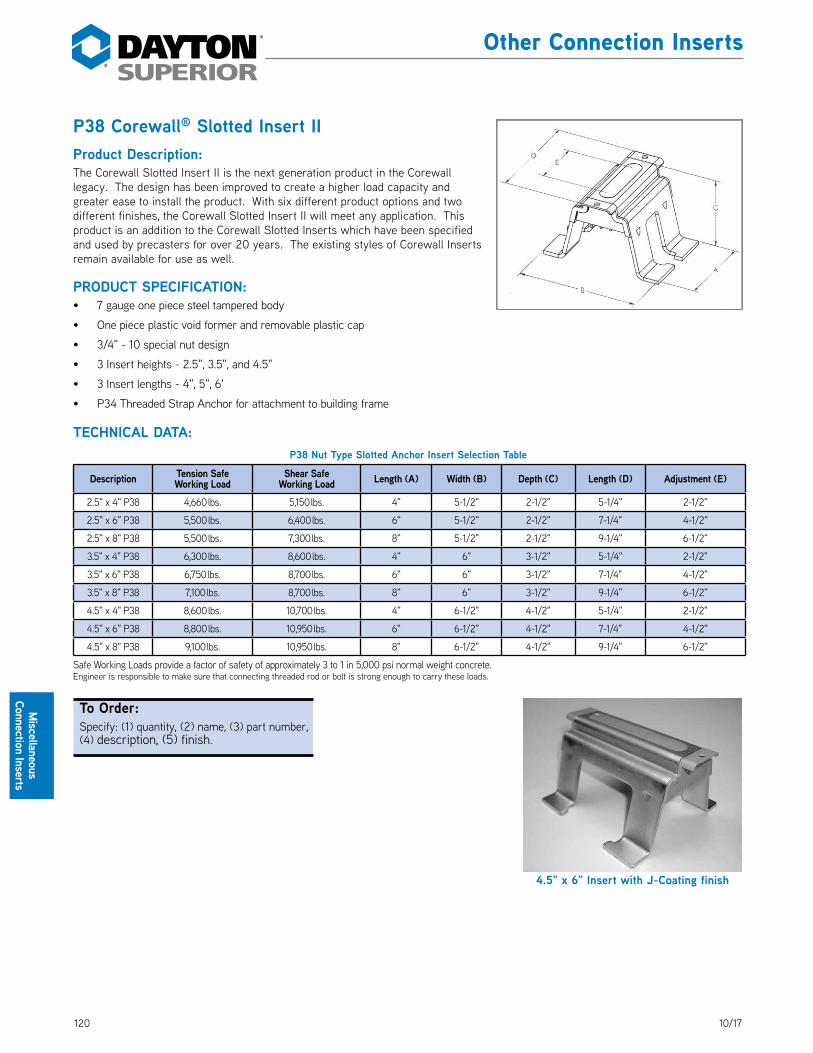
120 10/17
Miscellaneous
Connection Inserts
Other Connection Inserts
P38 Corewall® Slotted Insert IIProduct Description:The Corewall Slotted Insert II is the next generation product in the Corewall legacy. The design has been improved to create a higher load capacity and greater ease to install the product. With six different product options and two different finishes, the Corewall Slotted Insert II will meet any application. This product is an addition to the Corewall Slotted Inserts which have been specified and used by precasters for over 20 years. The existing styles of Corewall Inserts remain available for use as well. DS_P38
PRODUCT SPECIFICATION:• 7 gauge one piece steel tampered body
• One piece plastic void former and removable plastic cap
• 3/4" - 10 special nut design
• 3 Insert heights - 2.5", 3.5", and 4.5"
• 3 Insert lengths - 4", 5", 6'
• P34 Threaded Strap Anchor for attachment to building frame
TECHNICAL DATA:P38 Nut Type Slotted Anchor Insert Selection Table
Description Tension SafeWorking Load
Shear SafeWorking Load Length (A) Width (B) Depth (C) Length (D) Adjustment (E)
2.5" x 4" P38 4,660 lbs. 5,150 lbs. 4" 5-1/2" 2-1/2" 5-1/4" 2-1/2"
2.5" x 6" P38 5,500 lbs. 6,400 lbs. 6" 5-1/2" 2-1/2" 7-1/4" 4-1/2"
2.5" x 8" P38 5,500 lbs. 7,300 lbs. 8" 5-1/2" 2-1/2" 9-1/4" 6-1/2"
3.5" x 4" P38 6,300 lbs. 8,600 lbs. 4" 6" 3-1/2" 5-1/4" 2-1/2"
3.5" x 6" P38 6,750 lbs. 8,700 lbs. 6" 6" 3-1/2" 7-1/4" 4-1/2"
3.5" x 8" P38 7,100 lbs. 8,700 lbs. 8" 6" 3-1/2" 9-1/4" 6-1/2"
4.5" x 4" P38 8,600 lbs. 10,700 lbs. 4" 6-1/2" 4-1/2" 5-1/4" 2-1/2"
4.5" x 6" P38 8,800 lbs. 10,950 lbs. 6" 6-1/2" 4-1/2" 7-1/4" 4-1/2"
4.5" x 8" P38 9,100 lbs. 10,950 lbs. 8" 6-1/2" 4-1/2" 9-1/4" 6-1/2"
Safe Working Loads provide a factor of safety of approximately 3 to 1 in 5,000 psi normal weight concrete.Engineer is responsible to make sure that connecting threaded rod or bolt is strong enough to carry these loads.
4.5" x 6" Insert with J-Coating finish
To Order:Specify: (1) quantity, (2) name, (3) part number, (4) description, (5) finish.

12110/17
Misc
ellan
eous
Co
nnec
tion
Inse
rts
Other Connection Inserts
Corner Detail-3"
1-1/4"
3/4" Minimum
Cover
4"or 6"
2–#4Stepped Hairpins
3/4" Minimum Cover
Plan
Section
3"
3/4" Minimum
Cover
4" or 6"
3/4" Minimum Cover
3–#4Stepped Hairpins
3"
Plan
Section3/4" Minimum Cover
1-1/4"
1-1/4"
Corner Detail- 4" or 6"
3/4" Minimum Cover
2–#4 Stepped Hairpins
3"
Plan
Section3/4" Minimum Cover
Edge Perpendicular Detail
1-1/4"
3–#4 Stepped Hairpins
3/4" Minimum Cover
Plan
Section 3/4" Minimum Cover
3/4" Minimum
Cover
8"12"
8"12"
2"
Slot Details
C1-1/2"
2-1/2"
1-1/2" 1-1/2" 3"
2"
1-1/4"
11/16" 5/8" 3"
8" Insert
6" Insert
4" Insert
2-1/2"
Stepped Hairpin
Half Stepped Hairpin
Varies to suit
minimum cover
Varies #4 Rebar
3-1/2" Out/Out
1-3/4" Out/Out
#4 Rebar
1'-6"
1'-6"
A variety of configurations of extra reinforcing bars can be easily placed through the slotted holes in the legs of he insert. This will allow the insert to be used in seismic areas, as well as close to corners or edges of a precast concrete panel.
Corewall® Edge and Corner DetailsMinimum edge distance, without the use of additional reinforcing steel, is shown below. Edge distance can be reduced if additional reinforcing steel is installed in the insert slots, as shown.
3/4" Minimum Cover
Edge Parallel Detail-

122 10/17
Miscellaneous
Connection Inserts
Other Connection Inserts
P12D Dur-O-Web® Shear ReinforcementThe Dayton Superior P12D Dur-O-Web is a prefabricated structural web reinforcement assembly that has been developed to replace conventional U-shaped and closed stirrups. The vertical steel wires provide reinforcement for the applied shear stresses. The double, horizontal side wires at the top and bottom of the assembly develop the required anchorage for the vertical wire reinforcement. The design of Dur-O-Web allows the spacing and size of both the vertical and horizontal wires to vary to meet your design requirements. DS_P12
AvailabilityDayton Superior Dur-O-Web is shipped in bundles containing 500 ft. (50 pcs. of 10'-0" long units). Lengths other than 10'-0" can be supplied on special order. The standard finish is bright basic. Galvanized wire, hot dipped galvanized and epoxy coated finishes are also available on special order.
While Dur-O-Web is normally supplied with uniform spacing of vertical wires, variable spacing is available.
Benefits• Ideal shear reinforcement for prestressed/precast concrete double tees, other precast elements having narrow webs, or where space is limited
• Wide variety of wire sizes and spacings
• Ready to use
• Reduces costs by eliminating the cutting and bending of standard rebars or mesh
• Easy to place
• Available in standard 10'-0" lengths
• Serves as a mesh support in double tee flanges
• The ability to vary wire diameters and spacing guarantees the most economical solution to your reinforcement requirements
ApprovalsThe use of Dayton Superior Dur-O-Web Shear Reinforcement to replace open and closed stirrups is allowed by American Concrete Institute (ACI-318) Standard Building Code Requirements for Concrete Structures, and Canadian Standards Association Standard CAN3A23.3 Design of Concrete Structures for Buildings.
Using the Selection TableThe P12D Dur-O-Web selection table, shown below, shows the diameter and area of the vertical shear reinforcement wires that are available. It also lists the minimum size horizontal anchor wire that ASTM standards require. In addition, the area of shear reinforcement per foot is shown for the various spacing of the vertical shear reinforcement selected.
Example:A required shear steel area of 0.100 sq. in. per foot can be provided by using 1 gauge vertical wires spaced at 7-1/2" centers with 7 gauge longitudinal side wires. This example would provide 0.101 sq. in. of steel reinforcement per foot. Another solution would be the use of 5 gauge vertical wires spaced at 4" centers with 10 gauge longitudinal side wires. This combination would provide 0.102 sq. in. of reinforcement per foot.
P12D Dur-O-Web Selection Table
Wire Size Wire Gauge Wire Dia.
Steel Area (sq
in)Weightlb / ft
Min. Side Wire
Gauge
Area of Steel (sq. in.) per Lineal Foot at Indicated Main Shear Reinforcement Spacing
2" 3" 4" 5" 6" 7" 7-1/2" 8" 9" 10" 11" 12"
W-7.4 0 0.306" 0.074 0.251 6 0.444 0.296 0.222 0.178 0.148 0.127 0.118 0.111 0.099 0.089 0.081 0.074W-6.3 1 0.283" 0.063 0.214 7 0.378 0.252 0.189 0.151 0.128 0.108 0.101 0.095 0.084 0.076 0.069 0.063W-5.4 2 0.263" 0.054" 0.184 8 0.324 0.216 0.162 0.130 0.108 0.093 0.086 0.081 0.072 0.065 0.059 0.054W-4.9 1/4" 0.250" 0.049" 0.167 9 0.294 0.196 0.147 0.118 0.098 0.084 0.078 0.074 0.065 0.059 0.053 0.049W-4.7 3 0.244" 0.047" 0.158 9 0.282 0.188 0.141 0.113 0.094 0.081 0.075 0.071 0.063 0.056 0.051 0.047W-4.0 4 0.225" 0.040" 0.135 10 0.240 0.160 0.120 0.096 0.080 0.069 0.064 0.060 0.053 0.048 0.044 0.040W-3.4 5 0.207" 0.034" 0.114 10 0.202 0.136 0.102 0.082 0.068 0.058 0.054 0.051 0.045 0.041 0.037 0.034W-2.9 6 0.192" 0.029" 0.098 10 0.174 0.116 0.087 0.070 0.058 0.050 0.046 0.044 0.039 0.035 0.032 0.029W-2.5 7 0.177" 0.025" 0.084 10 0.150 0.100 0.075 0.060 0.050 0.043 0.040 0.038 0.033 0.030 0.027 0.025W-2.1 8 0.162" 0.021" 0.070 10 0.126 0.084 0.062 0.050 0.042 0.036 0.034 0.032 0.028 0.025 0.023 0.021W-1.7 9 0.148" 0.017" 0.059 10 0.102 0.068 0.051 0.041 0.034 0.029 0.027 0.026 0.023 0.020 0.019 0.017W-1.4 10 0.135" 0.014" 0.049 10 0.084 0.056 0.042 0.034 0.028 0.024 0.022 0.021 0.019 0.017 0.015 0.014
P12D Dur-O-WebShear Reinforcement
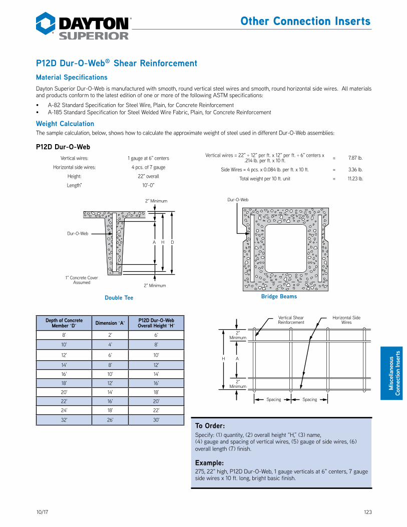
12310/17
Misc
ellan
eous
Co
nnec
tion
Inse
rts
Other Connection Inserts
P12D Dur-O-Web® Shear ReinforcementMaterial SpecificationsDayton Superior Dur-O-Web is manufactured with smooth, round vertical steel wires and smooth, round horizontal side wires. All materials and products conform to the latest edition of one or more of the following ASTM specifications:
• A-82 Standard Specification for Steel Wire, Plain, for Concrete Reinforcement• A-185 Standard Specification for Steel Welded Wire Fabric, Plain, for Concrete Reinforcement
Weight CalculationThe sample calculation, below, shows how to calculate the approximate weight of steel used in different Dur-O-Web assemblies:
P12D Dur-O-WebVertical wires: 1 gauge at 6" centers
Horizontal side wires: 4 pcs. of 7 gauge
Height: 22" overall
Length" 10'-0"
2" Minimum
Vertical ShearReinforcement
Horizontal Side Wires
2" Minimum
Spacing Spacing
AH
2" Minimum
2" Minimum
Dur-O-Web
1" Concrete Cover Assumed
Dur-O-Web
A H D
Double Tee Bridge Beams
Vertical wires = 22" ÷ 12" per ft. x 12" per ft. ÷ 6" centers x .214 lb. per ft. x 10 ft. = 7.87 lb.
Side Wires = 4 pcs. x 0.084 lb. per ft. x 10 ft. = 3.36 lb.
Total weight per 10 ft. unit = 11.23 lb.
Depth of Concrete Member “D” Dimension “A” P12D Dur-O-Web
Overall Height “H”
8' 2' 6'
10' 4' 8'
12' 6' 10'
14' 8' 12'
16' 10' 14'
18' 12' 16'
20' 14' 18'
22' 16' 20'
24' 18' 22'
32' 26' 30'To Order:Specify: (1) quantity, (2) overall height “H,” (3) name, (4) gauge and spacing of vertical wires, (5) gauge of side wires, (6) overall length (7) finish.
Example:275, 22" high, P12D Dur-O-Web, 1 gauge verticals at 6" centers, 7 gauge side wires x 10 ft. long, bright basic finish.

124 10/17
Notes and Sketches

12510/17
Sand
wic
h Pa
nel
Conn
ecto
rs
Sandwich Panel Connectors
P24 Delta TieThe Dayton Superior P24 Delta Tie is a unique insulated precast concrete panel connector. It allows the precaster to fabricate a highly energy-efficient, insulated precast concrete sandwich wall panel using the insulating foam of his choice. DS_P24
This versatile connector allows the foam insulation to be placed from panel edge to panel edge, eliminating thermal bridges and costly energy loss. The foam insulation is sandwiched between two concrete wythes, or layers, to form a long-lasting, energy-efficient precast concrete sandwich wall panel. The three wythes are tied together using P24 Delta Ties. Spacing of the Delta Ties varies, based on the panel’s required composite moment capacity.
The Delta Tie is produced using an engineered composite matrix. It consists of a geometrically configured, two-dimensional truss manufactured from continuous wound fiberglass embedded in an alkali resistant resin. The design of the Delta Tie produces a connector of remarkable strength and durability.
The non-metallic, non-corrosive design of the Delta Tie eliminates any thermal transfer through the panel, increasing the insulating efficiency of the panel.
Advantages• Increased load bearing.
• Stiffer insulated panels, easier to handle.
• Design flexibility.
• Material, labor and transportation cost reduction.
• Quick and easy installation.
• Applicable to all brands of foam panel insulation.
P24 Delta TieU.S. Patent #6761007

126 10/17
Sandwich Panel
Connectors
P24 Delta TieThe standard Delta Tie dimensions are shown in the accompanying detail.
The connector is designed so that it can be oriented in the panel either on end or side, depending on the thickness of the panel. For example, the 5" x 7" size can be used on its side in a six-inch panel or on end for thicker panels. The Delta Tie can be used with any rigid insulation from 1" to 4" thick. This versatile, dual-use feature adds to the Delta Tie’s effective application compatibility and, at the same time, reduces inventory and storage requirements.
In individual connector specimen and full size panel tests the Delta Tie has exhibited excellent loading behavior and load capacities.
Increased Load Bearing Tests have verified the excellent tension and shear strength characteristics of the Delta Tie insulated panel connector.
Stiffer Insulated Concrete PanelsThe inherent capabilities of the truss design greatly increase the stiffness of the panel. The added stiffness makes the panel easier to lift, handle, store and/or transport.
Design FlexibilityDue to the composite action gained by using the Delta Tie, panels may be cast in longer lengths or with thinner concrete wythes.
Cost SavingsThe Delta Tie design provides a fast and easy installation to save labor. It produces stiffer panels to lessen handling, storage and transportation concerns. The connector’s design flexibility allows the cost saving attributes to be designed into the panel. Delta Tie connectors are purchased as a separate item, allowing the precaster to provide the foam insulation of his choice.
Quick and Easy InstallationThe two-dimensional design of the Delta Tie lends itself to easy installation. No drilling or special tools required. Simply use the foam as a straight-edge template to quickly place the connectors.
Applicable to All Brands of Foam Panel InsulationThe Delta Tie is not sold as part of a package. It is sold separately and can be used with any brand of foam insulation supplied by the precaster.
The many Delta Tie advantages open up a wide area of possibilities for the precaster/designer/producer to improve production, efficiency and costs at his precasting operation.
The P24 Delta Tie has the following ultimate capacities:• 3,220 lbs. in shear.• 3,100 lbs. in tension.
Maximum recommended spacing is 8 square feet of panel per panel connector. For spacing in excess of 8 square feet of panel per connector, contact a Dayton Superior Technical Assistance.
• NFPA 285• ASTM E-119• Five Test Approved
1/2" Typ.
3"5"
7"5"
Sandwich Panel Connectors
To Order:Specify: (1) quantity, (2) name.
Example:500, P24 Delta Ties.

12710/17
Sand
wic
h Pa
nel
Conn
ecto
rs
P24 Delta Tie Design Table
Typical Delta Tie Placement
Composite Moment CapacityFor any given sandwich panel, the shear and moment diagrams define the required panel stiffness. The panel stiffness may be altered, as necessary, pending panel parameters, by adjusting the tie distribution as a function of the internal shear and moment forces. The two examples, below, illustrate the required stiffness (percent composite action) necessary to develop the shear and moment forces.
1. A panel measuring 37'-0" long by 6'-0" wide, with a 3-2-3 wythe pattern, must have a 5% composite action to achieve a flat lift with 4x2 rigging.
2. A 2-2-2 panel of same size requires a 10% composite action for the same rigging.
In order to employ the least amount of concrete to save weight, the percent of composite action must increase. A small upward adjustment can be realized by a minimal addition of connectors strategically placed at the zones of maximum shear.
0
2000
4000
Percent Composite
6000
8000
10000
12000
14000
16000
18000
200000
60% 70%50%40%30%20%10%0%
Chart based on 6'-0' ' Panel Widthf'c = 5,000 psifba = 424 psi
Mom
ent C
apac
ity (f
t-lb
s)
3-2-3
2-2-2
Notes: When composite action is not required, maximum connector spacing for a 3-2-3 panel is 8 sq. ft. per connector.
Test reports are available on request.
0%
10%
20%
eP
r)k(
noitc
A etiso
pm
oC t
nec
Square Feet Per Connector
30%
40%
50%
60%
6 7 8 9 10543210
Ipc = Partial Composite Moment of Inertiak = Percentage CompositeIcomp = Composite Moment of InertiaInc = Non-Composite Moment of Inertia
k(Icomp – Inc)100
Ipc = + Inc
No Composite Action25% Composite Action
4 sq. ft. per connector 8 sq. ft. per connector
Sandwich Panel Connectors
Ipc = Partial Composite Moment of Inertiak = Percentage CompositeIcomp = Composite Moment of InertiaInc = Non-Composite Moment of Inertia
Ipc = k(Icomp – Inc) + Inc 100
Chart based on 6'-0' ' Panel Widthf'c = 5,000 psifba = 424 psi
Square Feet Per Connector
Perc
ent C
ompo
site
Act
ion
(k)
Percent Complete
Mom
ent C
opac
ity (
ft-lb
s)

128 10/17
Sandwich Panel
Connectors
P24 Delta Tie Insulated Panel Installation Sequence
1. Construct form, place reinforcing mesh, lifting inserts, etc. Place and screed the concrete for the bottom wythe.
2. While the bottom wythe concrete is still pliable, lay the first course of insulating foam flush against the form. Typically, the first course of foam will be 12' ' running the length of the panel. Utilize the edge of the foam as a template and push each Delta Tie down into the bottom wythe.
3. Continue to place the connectors in their proper positions along the first course of insulation.
4. Add the remaining courses of insulation and connectors.*
5. When all of the foam sections and connectors have been placed, the top concrete wythe is poured and screeded as necessary.
6. After proper concrete set, the panel may be removed from the form and the process repeated.
* Foam-backed tape is available for sealing the insulation joints, if necessary.
Sandwich Panel Connectors

12910/17
Sand
wic
h Pa
nel
Conn
ecto
rs
Sandwich Panel Connectors
P24XL Delta TieThe Dayton Superior P24XL Delta Tie is a two-dimensional truss of structurally non-conductive, non-metallic, non-corrosive fiber composite used as a wythe connector for concrete sandwich panel construction. The P24XL Delta Tie is just like the widely used P24, but it is designed for applications with 5" to 8" of insulation.
The size is 9" x 11" x 5/32" with ½" tabs and v-notch installation aides.
Ties are normally installed in the seams between sheets of insulation, or the insulation can be cut and the ties positioned through the insulation. For insulation with an integral vapor barrier, it is important to insure that it is also cut so as to not interfere with the concrete tie embedment. Ties must be installed a maximum of 12" from any edge or opening. A typical spacing pattern provides one tie for every 2-8 square feet of panel surface area. The preferred tie orientation is parallel to the height of the panel.
SpecificationsComposite Modulus: 8,370,000 psi
Composite Tensile Strength: 167, 400 psi
Poisson's Ratio: 0.26
Density: 110 lbs/cu ft
Alkali Resistance: Made from continuous wound alkali resistant glass fibers in an alkali resistant epoxy bisphenol A vinyl ester resin. The resin is rated for continuous alkali exposure at up to 180°F, and is also UV resistant. The resin's glass transition temperature is 285°F, and its melting point is 650°F.
Glass Content: 1.45 micron, 2.4 g/m, 14GPa tensile strength, continuous roving fibers at 77% by weight. The continuous operating temperature of the 19% zirconium glass fiber is 900°F.
Thermal Conductivity: 0.1447 BTU/hr F ft (0.25 W/m•C) where Insulation Board is 0.014, and Concrete is 1.2414. The Delta Tie R-Value is 0.576 sq ft F hr/BTU per inch of thickness.
CTE: Is matched to concrete at 0.0000055 in/in/F.
Delta Tie Type Insulation Thickness (inches) Tension Capacity * (lbs) Shear Capacity * (lbs)P24 (5"x7") 1-4 3100 3400
P24XL (9"x11") 1-5 5800 3700
P24XL (9"x11") 6 3400 3075
P24XL (9"x11") 7 4000 2800
P24XL (9"x11") 8 3200 1650
* Ultimate Strength per Tie. Factor of Safety is variable based on the panel configuration.
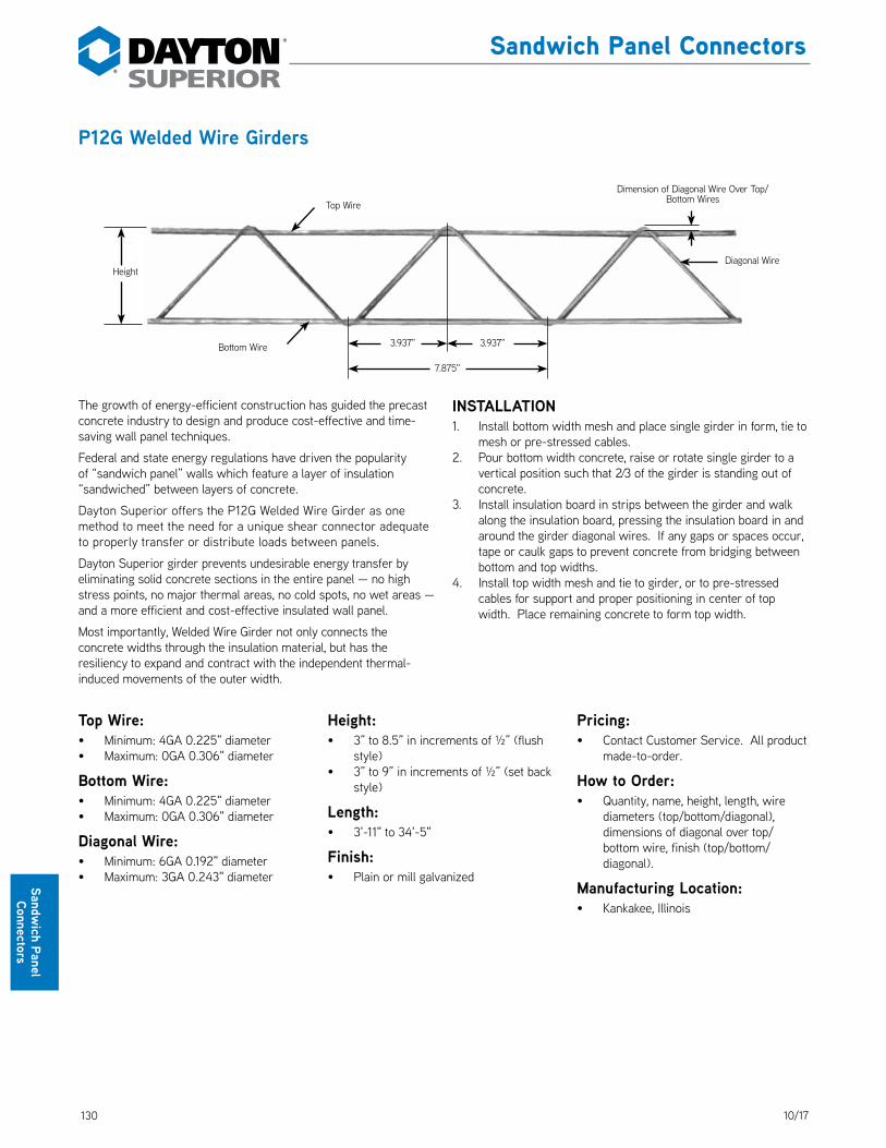
130 10/17
Sandwich Panel
Connectors
Sandwich Panel Connectors
P12G Welded Wire Girders
The growth of energy-efficient construction has guided the precast concrete industry to design and produce cost-effective and time-saving wall panel techniques. DS_P12G
Federal and state energy regulations have driven the popularity of “sandwich panel” walls which feature a layer of insulation “sandwiched” between layers of concrete.
Dayton Superior offers the P12G Welded Wire Girder as one method to meet the need for a unique shear connector adequate to properly transfer or distribute loads between panels.
Dayton Superior girder prevents undesirable energy transfer by eliminating solid concrete sections in the entire panel — no high stress points, no major thermal areas, no cold spots, no wet areas — and a more efficient and cost-effective insulated wall panel.
Most importantly, Welded Wire Girder not only connects the concrete widths through the insulation material, but has the resiliency to expand and contract with the independent thermal-induced movements of the outer width.
INSTALLATION1. Install bottom width mesh and place single girder in form, tie to
mesh or pre-stressed cables.2. Pour bottom width concrete, raise or rotate single girder to a
vertical position such that 2∕3 of the girder is standing out of concrete.
3. Install insulation board in strips between the girder and walk along the insulation board, pressing the insulation board in and around the girder diagonal wires. If any gaps or spaces occur, tape or caulk gaps to prevent concrete from bridging between bottom and top widths.
4. Install top width mesh and tie to girder, or to pre-stressed cables for support and proper positioning in center of top width. Place remaining concrete to form top width.
Diagonal Wire
7.875"
3.937" 3.937"
Height
Top Wire
Bottom Wire
Dimension of Diagonal Wire Over Top/Bottom Wires
Top Wire:• Minimum: 4GA 0.225" diameter• Maximum: 0GA 0.306" diameter
Bottom Wire:• Minimum: 4GA 0.225" diameter• Maximum: 0GA 0.306" diameter
Diagonal Wire:• Minimum: 6GA 0.192" diameter• Maximum: 3GA 0.243" diameter
Height:• 3” to 8.5” in increments of ½” (flush
style)• 3” to 9” in increments of ½” (set back
style)
Length:• 3'-11" to 34'-5"
Finish:• Plain or mill galvanized
Pricing:• Contact Customer Service. All product
made-to-order.
How to Order:• Quantity, name, height, length, wire
diameters (top/bottom/diagonal), dimensions of diagonal over top/bottom wire, finish (top/bottom/diagonal).
Manufacturing Location:• Kankakee, Illinois
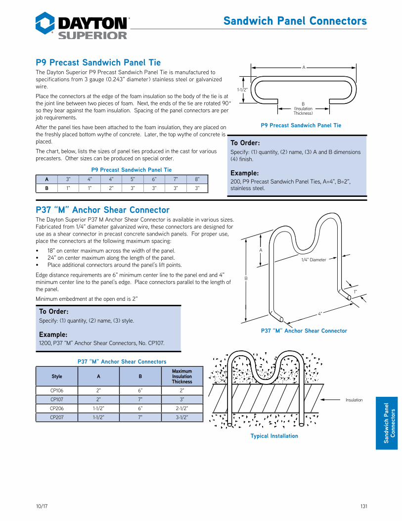
13110/17
Sand
wic
h Pa
nel
Conn
ecto
rs
P9 Precast Sandwich Panel TieThe Dayton Superior P9 Precast Sandwich Panel Tie is manufactured to specifications from 3 gauge (0.243" diameter) stainless steel or galvanized wire. DS_P9
Place the connectors at the edge of the foam insulation so the body of the tie is at the joint line between two pieces of foam. Next, the ends of the tie are rotated 90˚ so they bear against the foam insulation. Spacing of the panel connectors are per job requirements.
After the panel ties have been attached to the foam insulation, they are placed on the freshly placed bottom wythe of concrete. Later, the top wythe of concrete is placed.
The chart, below, lists the sizes of panel ties produced in the cast for various precasters. Other sizes can be produced on special order.
P9 Precast Sandwich Panel TieA 3" 4" 4" 5" 6" 7" 8"
B 1" 1" 2" 3" 3" 3" 3"
P37 “M” Anchor Shear ConnectorThe Dayton Superior P37 M Anchor Shear Connector is available in various sizes. Fabricated from 1/4" diameter galvanized wire, these connectors are designed for use as a shear connector in precast concrete sandwich panels. For proper use, place the connectors at the following maximum spacing: DS_P37
• 18" on center maximum across the width of the panel.• 24" on center maximum along the length of the panel.• Place additional connectors around the panel’s lift points.
Edge distance requirements are 6" minimum center line to the panel end and 4" minimum center line to the panel’s edge. Place connectors parallel to the length of the panel.
Minimum embedment at the open end is 2"
To Order:Specify: (1) quantity, (2) name, (3) style.
Example:1200, P37 “M” Anchor Shear Connectors, No. CP107.
P37 “M” Anchor Shear Connectors
Style A BMaximum Insulation Thickness
CP106 2" 6" 2"
CP107 2" 7" 3"
CP206 1-1/2" 6" 2-1/2"
CP207 1-1/2" 7" 3-1/2"
B(Insulation Thickness)
A
1-1/2"
P9 Precast Sandwich Panel Tie
Typical Installation
Insulation
P37 “M” Anchor Shear Connector
A
1"
1/4" Diameter
B
4"
Sandwich Panel Connectors
To Order:Specify: (1) quantity, (2) name, (3) A and B dimensions (4) finish.
Example:200, P9 Precast Sandwich Panel Ties, A=4", B=2", stainless steel.
132 10/17
Notes and Sketches

13310/17
Mis
cella
neou
s Pr
oduc
ts
Strand Restraining Devices
Prestress Strand Restraining DevicesBy deflecting some of the prestressing strands, in a precast prestressed concrete beam, a more favorable distribution of stresses within the concrete beam is obtained. When using deflected strands, the eccentricity of the prestressing force is reduced in the area of decreasing dead load moment. By reducing the tensile stresses in the concrete, the load that can be applied to the beam can be increased by an amount equal to the weight of the beam itself.
The benefits obtainable through strand deflection are such that many precast prestressed concrete plants are designed so that the prestress strands can be deflected. When using depressed strands, it is necessary that strand restraining devices be provided at the points within the concrete beam where the strand deflections occur.
Working closely with many prestressed concrete producers, Dayton Superior has developed a complete line of strand restraining devices. Since 1958, Dayton Superior strand deflection devices have been recognized and accepted as the industry standard. All units are manufactured on a production basis and are produced with positive (no welding) mechanical connections.
These units maintain a clear distance of 1-1/2" from bottom of the strand restraining device to beam bottom yet still hold a 2" dimension from the centerline of the strand to the beam bottom. DS_PrestressStrand
Note: For more information on the complete prestressing system or individual components, request a copy of the Prestress Strand Deflection Device Handbook
Illustration of swivel action as strand restraining device responds to
strand tensioning.Large variety of styles available to fit your needs
View of Strand Restraining Device “Free-turning” rollers contribute additional
safety, reducing frictional resistance.
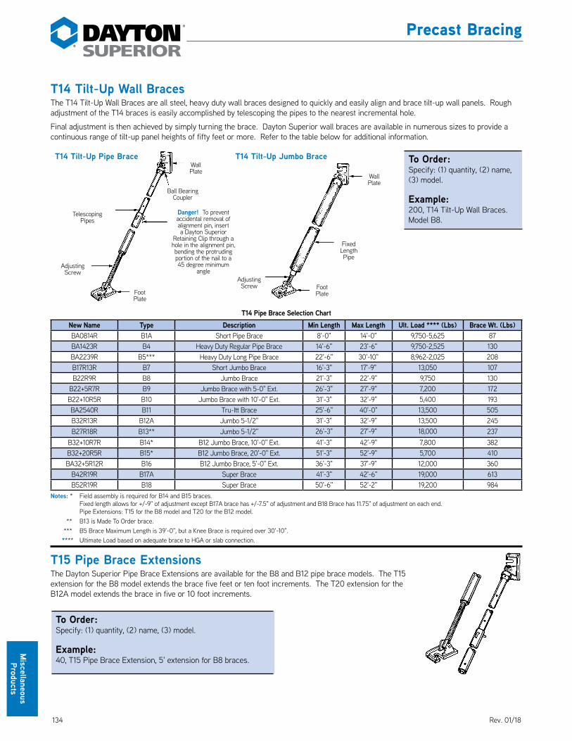
134 10/17
Miscellaneous Products
Precast Bracing
T14 Tilt-Up Wall BracesThe T14 Tilt-Up Wall Braces are all steel, heavy duty wall braces designed to quickly and easily align and brace tilt-up wall panels. Rough adjustment of the T14 braces is easily accomplished by telescoping the pipes to the nearest incremental hole.
Final adjustment is then achieved by simply turning the brace. Dayton Superior wall braces are available in numerous sizes to provide a continuous range of tilt-up panel heights of fifty feet or more. Refer to the table below for additional information.
T14 Pipe Brace Selection ChartNew Name Type Description Min Length Max Length Ult. Load **** (Lbs) Brace Wt. (Lbs)BA0814R B1A Short Pipe Brace 8'-0" 14'-0" 9,750-5,625 87BA1423R B4 Heavy Duty Regular Pipe Brace 14'-6" 23'-6" 9,750-2,525 130BA2239R B5*** Heavy Duty Long Pipe Brace 22'-6" 30'-10" 8,962-2,025 208B17R13R B7 Short Jumbo Brace 16'-3" 17'-9" 13,050 107B22R9R B8 Jumbo Brace 21'-3" 22'-9" 9,750 130
B22+5R7R B9 Jumbo Brace with 5-0" Ext. 26'-3" 27'-9" 7,200 172B22+10R5R B10 Jumbo Brace with 10'-0" Ext. 31'-3" 32'-9" 5,400 193BA2540R B11 Tru-Itt Brace 25'-6" 40'-0" 13,500 505B32R13R B12A Jumbo 5-1/2" 31'-3" 32'-9" 13,500 245B27R18R B13** Jumbo 5-1/2" 26'-3" 27'-9" 18,000 237
B32+10R7R B14* B12 Jumbo Brace, 10'-0" Ext. 41'-3" 42'-9" 7,800 382B32+20R5R B15* B12 Jumbo Brace, 20'-0" Ext. 51'-3" 52'-9" 5,700 410BA32+5R12R B16 B12 Jumbo Brace, 5'-0" Ext. 36'-3" 37'-9" 12,000 360
B42R19R B17A Super Brace 41'-3" 42'-6" 19,000 613B52R19R B18 Super Brace 50'-6" 52'-2" 19,200 984
Notes: * Field assembly is required for B14 and B15 braces. Fixed length allows for +/-9" of adjustment except B17A brace has +/-7.5" of adjustment and B18 Brace has 11.75" of adjustment on each end. Pipe Extensions: T15 for the B8 model and T20 for the B12 model. ** B13 is Made To Order brace. *** B5 Brace Maximum Length is 39'-0", but a Knee Brace is required over 30'-10". **** Ultimate Load based on adequate brace to HGA or slab connection.
T15 Pipe Brace ExtensionsThe Dayton Superior Pipe Brace Extensions are available for the B8 and B12 pipe brace models. The T15 extension for the B8 model extends the brace five feet or ten foot increments. The T20 extension for the B12A model extends the brace in five or 10 foot increments.
Telescoping Pipes
Adjusting Screw
Foot Plate
Wall Plate
Ball Bearing Coupler
Fixed Length Pipe
Wall Plate
Adjusting Screw Foot
Plate
Danger! To prevent accidental removal of alignment pin, insert a Dayton Superior
Retaining Clip through a hole in the alignment pin, bending the protruding portion of the nail to a 45 degree minimum
angle
T14 Tilt-Up Pipe Brace T14 Tilt-Up Jumbo Brace To Order:Specify: (1) quantity, (2) name, (3) model.
Example:200, T14 Tilt-Up Wall Braces. Model B8.
To Order:Specify: (1) quantity, (2) name, (3) model.
Example:40, T15 Pipe Brace Extension, 5' extension for B8 braces.
Rev. 01/18
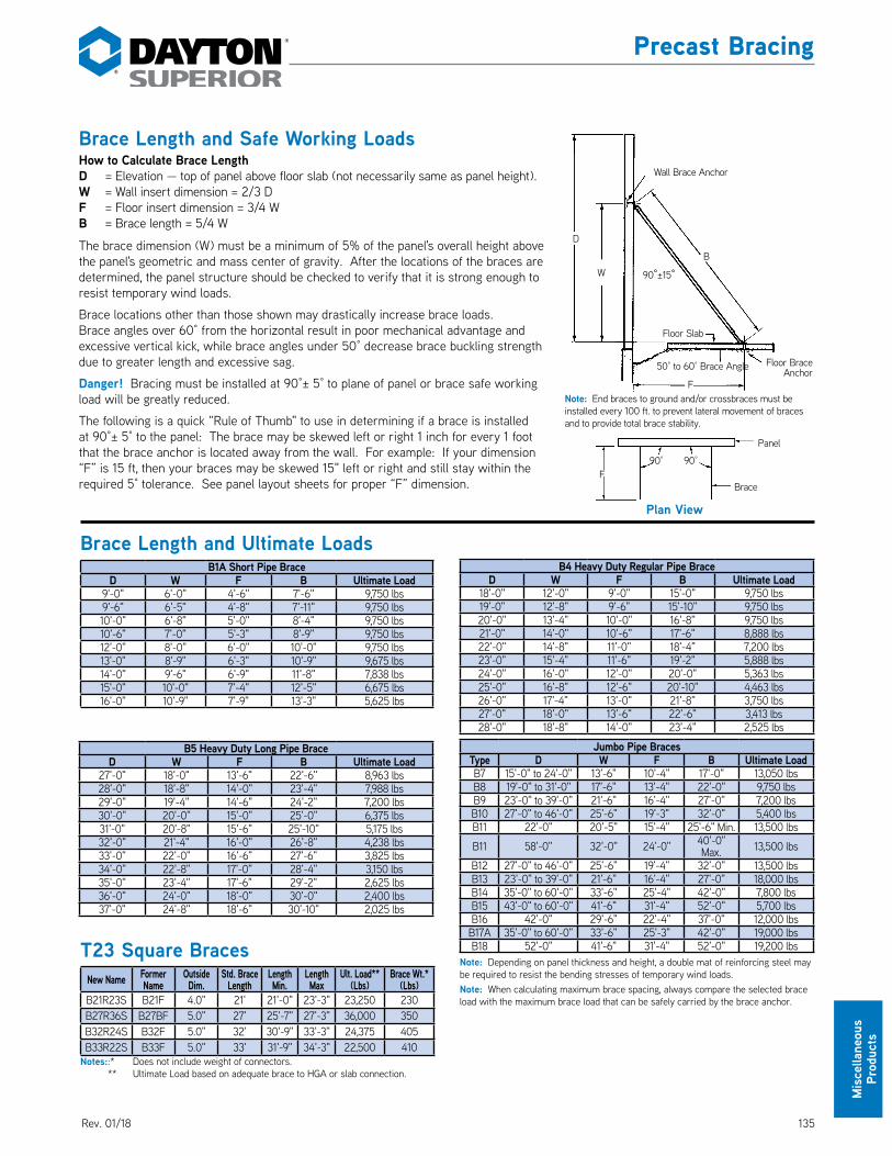
13510/17
Mis
cella
neou
s
Prod
ucts
Brace Length and Ultimate LoadsB1A Short Pipe Brace
D W F B Ultimate Load9'-0" 6'-0" 4'-6" 7'-6" 9,750 lbs9'-6" 6'-5" 4'-8" 7'-11" 9,750 lbs10'-0" 6'-8" 5'-0" 8'-4" 9,750 lbs10'-6" 7'-0" 5'-3" 8'-9" 9,750 lbs12'-0" 8'-0" 6'-0" 10'-0" 9,750 lbs13'-0" 8'-9" 6'-3" 10'-9" 9,675 lbs14'-0" 9'-6" 6'-9" 11'-8" 7,838 lbs15'-0" 10'-0" 7'-4" 12'-5" 6,675 lbs16'-0" 10'-9" 7'-9" 13'-3" 5,625 lbs
B4 Heavy Duty Regular Pipe BraceD W F B Ultimate Load
18'-0" 12'-0" 9'-0" 15'-0" 9,750 lbs19'-0" 12'-8" 9'-6" 15'-10" 9,750 lbs20'-0" 13'-4" 10'-0" 16'-8" 9,750 lbs21'-0" 14'-0" 10'-6" 17'-6" 8,888 lbs22'-0" 14'-8" 11'-0" 18'-4" 7,200 lbs23'-0" 15'-4" 11'-6" 19'-2" 5,888 lbs24'-0" 16'-0" 12'-0" 20'-0" 5,363 lbs25'-0" 16'-8" 12'-6" 20'-10" 4,463 lbs26'-0" 17'-4" 13'-0" 21'-8" 3,750 lbs27'-0" 18'-0" 13'-6" 22'-6" 3,413 lbs28'-0" 18'-8" 14'-0" 23'-4" 2,525 lbs
B5 Heavy Duty Long Pipe BraceD W F B Ultimate Load
27'-0" 18'-0" 13'-6" 22'-6" 8,963 lbs28'-0" 18'-8" 14'-0" 23'-4" 7,988 lbs29'-0" 19'-4" 14'-6" 24'-2" 7,200 lbs30'-0" 20'-0" 15'-0" 25'-0" 6,375 lbs31'-0" 20'-8" 15'-6" 25'-10" 5,175 lbs32'-0" 21'-4" 16'-0" 26'-8" 4,238 lbs33'-0" 22'-0" 16'-6" 27'-6" 3,825 lbs34'-0" 22'-8" 17'-0" 28'-4" 3,150 lbs35'-0" 23'-4" 17'-6" 29'-2" 2,625 lbs36'-0" 24'-0" 18'-0" 30'-0" 2,400 lbs37'-0" 24'-8" 18'-6" 30'-10" 2,025 lbs
Jumbo Pipe BracesType D W F B Ultimate LoadB7 15'-0" to 24'-0" 13'-6" 10'-4" 17'-0" 13,050 lbsB8 19'-0" to 31'-0" 17'-6" 13'-4" 22'-0" 9,750 lbsB9 23'-0" to 39'-0" 21'-6" 16'-4" 27'-0" 7,200 lbsB10 27'-0" to 46'-0" 25'-6" 19'-3" 32'-0" 5,400 lbsB11 22'-0" 20'-5" 15'-4" 25'-6" Min. 13,500 lbs
B11 58'-0" 32'-0" 24'-0" 40'-0" Max. 13,500 lbs
B12 27'-0" to 46'-0" 25'-6" 19'-4" 32'-0" 13,500 lbsB13 23'-0" to 39'-0" 21'-6" 16'-4" 27'-0" 18,000 lbsB14 35'-0" to 60'-0" 33'-6" 25'-4" 42'-0" 7,800 lbsB15 43'-0" to 60'-0" 41'-6" 31'-4" 52'-0" 5,700 lbsB16 42'-0" 29'-6" 22'-4" 37'-0" 12,000 lbs
B17A 35'-0" to 60'-0" 33'-6" 25'-3" 42'-0" 19,000 lbsB18 52'-0" 41'-6" 31'-4" 52'-0" 19,200 lbs
Note: Depending on panel thickness and height, a double mat of reinforcing steel may be required to resist the bending stresses of temporary wind loads.Note: When calculating maximum brace spacing, always compare the selected brace load with the maximum brace load that can be safely carried by the brace anchor.
Wall Brace Anchor
90°±15°W
D
B
F
Floor Slab
50° to 60° Brace Angle Floor Brace Anchor
Note: End braces to ground and/or crossbraces must be installed every 100 ft. to prevent lateral movement of braces and to provide total brace stability.
Brace Length and Safe Working LoadsHow to Calculate Brace LengthD = Elevation — top of panel above floor slab (not necessarily same as panel height).W = Wall insert dimension = 2/3 DF = Floor insert dimension = 3/4 WB = Brace length = 5/4 W
The brace dimension (W) must be a minimum of 5% of the panel's overall height above the panel's geometric and mass center of gravity. After the locations of the braces are determined, the panel structure should be checked to verify that it is strong enough to resist temporary wind loads.
Brace locations other than those shown may drastically increase brace loads. Brace angles over 60° from the horizontal result in poor mechanical advantage and excessive vertical kick, while brace angles under 50° decrease brace buckling strength due to greater length and excessive sag.
Danger! Bracing must be installed at 90°± 5° to plane of panel or brace safe working load will be greatly reduced.
The following is a quick “Rule of Thumb" to use in determining if a brace is installed at 90°± 5° to the panel: The brace may be skewed left or right 1 inch for every 1 foot that the brace anchor is located away from the wall. For example: If your dimension “F” is 15 ft, then your braces may be skewed 15" left or right and still stay within the required 5° tolerance. See panel layout sheets for proper “F” dimension.
Panel
Brace
Plan View
90°90°F
Precast Bracing
T23 Square BracesNew Name Former
NameOutside Dim.
Std. Brace Length
Length Min.
Length Max
Ult. Load** (Lbs)
Brace Wt.* (Lbs)
B21R23S B21F 4.0" 21' 21'-0" 23'-3" 23,250 230B27R36S B27BF 5.0" 27' 25'-7" 27'-3" 36,000 350B32R24S B32F 5.0" 32' 30'-9" 33'-3" 24,375 405B33R22S B33F 5.0" 33' 31'-9" 34'-3" 22,500 410
Notes::* Does not include weight of connectors. ** Ultimate Load based on adequate brace to HGA or slab connection.
Rev. 01/18

136 10/17
Miscellaneous Products
Brace LoadingBracing recommendations are for the sole purpose of temporarily bracing fully erected concrete tilt-up panels during construction — against wind loads only. This temporary bracing design is based on the latest editions of The American Society of Civil Engineers (ASCE-7) Minimum Design Loads for Building and other Structures, ASCE-37 Design Loads of Structures During Construction, and the Tilt-Up Concrete Association Guideline for Temporary Wind Bracing to determine the wind loads that are applied to an erected tilt-up panel. The ASCE standards and the TCA guideline allow the basic wind speed, which is based on a 15% probability of three second gust wind speed in exceedence at thirty-three feet above ground level. DS_BraceLoading
Brace anchors and main, knee, lateral and/or end braces are not designed or intended to sustain impact loads. Precautions must be taken to arrange the panel erection sequence so as to avoid the potential for impacting upright panels or portions of the bracing system. Bracing recommendations for other loads or forces that might be applied to the bracing system are beyond the scope of Dayton Superior. For bracing recommendations other than wind loads, the user should engage a design agency with capabilities of performing such a service.
Brace RemovalThis bracing system is designed to temporarily support panels against wind loads until the building structure is complete and self supporting. The bracing system should never be disconnected or removed until the panels are secured by the permanent structural connections and all lateral load resisting systems are in place.
If the structural documents do not indicate when the temporary bracing system can be removed, the engineer of record should be consulted.
Safety Notes:• Panel should be plumb with braces and knee braces installed before crane releases panel.• Lateral bracing should be installed immediately upon the crane and crew clearing the braces and before the next panel is erected.• Lateral bracing must be continuous, connected at each brace, and tied off with end braces at the end of each line.• Panels require a minimum of two braces per panel.• End braces to ground and/or cross braces must be installed every 100 ft. to prevent lateral movement of braces and to provide total
brace stability.• All members of the brace system must be in place and secured at the end of each day.• Knee and lateral bracing must be located at mid-length of pipe brace.• Knee brace must be firmly fixed at bottom end to prevent possible upward buckling of main brace.• Do not erect panels or continue working during excessive windy or adverse weather conditions.• All brace inserts should be a minimum of 12" from any panel edge, opening, control joint or construction joint.• Panel bracing is designed to withstand specified wind loads until panels are connected to the structural system of the building. Do
not remove any members of the bracing system until all structural connections are completed.• Use only the brace type as noted on the Panel Layout Sheet. No substitute brace hardware shall be used and all braces must be
positioned at the specified locations.• For special bracing conditions that require deviation from the bracing dimensions shown on the Panel Layout Sheet contact Dayton
Superior for recommendations.• See Panel Layout Sheet for type of brace, number of braces per panel, as well as knee and lateral bracing requirements.• Welding or bolting the tilt-up panels in place might preclude the use of braces.• After winds of 35 mph or more have been experienced at the job site, the tilt-up contractor must check the tightness of the bolts that
secure the wall and foot plates to the concrete. Re-tightening of these bolts to the proper torque will assure that the pipe braces are secure.
• The safe working load of the panel’s bracing system may be drastically reduced if other types of brace anchors are used as part of this project’s bracing system, other than specified brace anchors.
Warning! Failure to install knee, lateral and end braces (when required) will greatly reduce the safe working load of the specified brace and may allow panels to fall causing severe injury or death.
Precast Bracing
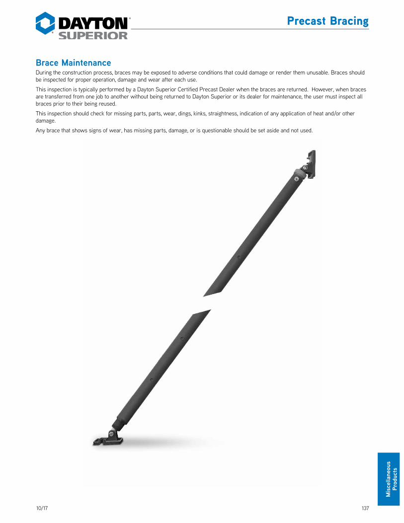
13710/17
Mis
cella
neou
s Pr
oduc
ts
Brace MaintenanceDuring the construction process, braces may be exposed to adverse conditions that could damage or render them unusable. Braces should be inspected for proper operation, damage and wear after each use.
This inspection is typically performed by a Dayton Superior Certified Precast Dealer when the braces are returned. However, when braces are transferred from one job to another without being returned to Dayton Superior or its dealer for maintenance, the user must inspect all braces prior to their being reused.
This inspection should check for missing parts, parts, wear, dings, kinks, straightness, indication of any application of heat and/or other damage.
Any brace that shows signs of wear, has missing parts, damage, or is questionable should be set aside and not used.
Precast Bracing

138 10/17
Miscellaneous Products
Accubrace® Total Bracing SystemAn integrated,in-line total bracing system designed to decrease labor costs and increase project efficiency
The Accubrace Total Bracing System is designed for rapid installation and the ability to immediately load the helical ground anchor for unsurpassed speed and efficiency on any tilt-up or precast project. Bracing products are warehoused at regional offices and can quickly be transported to job sites.
Custom braces can also be designed and manufactured to meet any project application.
Dayton Superior provides safe engineered solution by installing Helical Ground Anchors (HGAs) and renting necessary components.
Precast Bracing
KEY:B Brace lengthW Brace connection height
above bottom of panelH Panel height
X HGA Mark - Horizontal distance from panel face
G HGA elevation +/- relative to panel bottom
Helical Ground Anchor (HGA) Helical Plates
Ground Line7'
(min.
)
Tran
sition
Con
necto
r
Brace
Angle
Wall B
race
Footing Top of Footing
Elevation
Slab
PanelFeatures• HGAs are engineered alternative to concrete deadmen
and/or floor slabs, reducing the associated time and labor costs
• Rapid, all-weather brace installation — immediate loading when used with the helical ground anchor
• Remove and relocate ground anchors if installation of braces requires adjustment
• Anchor location is adaptable — can be installed inside or outside of structure
• Bracing on the outside of wall simplifies structural steel erection especially in multi-story buildings
• Bracing on the inside of wall eliminates holes in floor slab and vapor barrier
• Integrated in-line connection to the brace utilizing a HGA and Transition Brace Connector (STBC)
• Dayton Superior offers Professional Engineer review and stamp services
• Removable and reusable• HGAs can be used with any Dayton Superior brace• Reduces the number of braces needed if HGAs used
with high capacity braces
Rev. 03/18
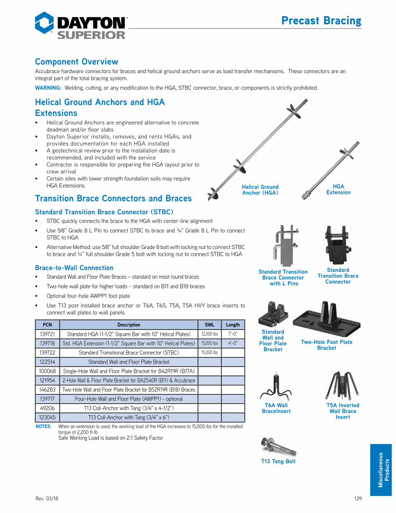
13910/17
Mis
cella
neou
s
Prod
ucts
Helical Ground Anchors and HGA Extensions• Helical Ground Anchors are engineered alternative to concrete
deadman and/or floor slabs• Dayton Superior installs, removes, and rents HGAs, and
provides documentation for each HGA installed• A geotechnical review prior to the installation date is
recommended, and included with the service• Contractor is responsible for preparing the HGA layout prior to
crew arrival• Certain sites with lower strength foundation soils may require
HGA Extensions.
Transition Brace Connectors and BracesStandard Transition Brace Connector (STBC)• STBC quickly connects the brace to the HGA with center-line alignment
• Use 5⁄8" Grade 8 L Pin to connect STBC to brace and ¾" Grade 8 L Pin to connect STBC to HGA
• Alternative Method: use 5⁄8" full shoulder Grade 8 bolt with locking nut to connect STBC to brace and ¾" full shoulder Grade 5 bolt with locking nut to connect STBC to HGA
Brace-to-Wall Connection• Standard Wall and Floor Plate Braces – standard on most round braces
• Two-hole wall plate for higher loads – standard on B11 and B18 braces
• Optional four-hole AWPP1 foot plate
• Use T13 post installed brace anchor or T6A, T6S, T5A, T5A HVY brace inserts to connect wall plates to wall panels
PCN Description SWL Length
139721 Standard HGA (1-1/2" Square Bar with 10" Helical Plates) 12,000 lbs 7'-0"
139718 Std. HGA Extension (1-1/2" Square Bar with 10" Helical Plates) 15,000 lbs 4'-0"
139722 Standard Transitional Brace Connector (STBC) 15,000 lbs
122514 Standard Wall and Floor Plate Bracket100068 Single-Hole Wall and Floor Plate Bracket for B42R19R (B17A)121954 2-Hole Wall & Floor Plate Bracket for BA2540R (B11) & Accubrace146283 Two-Hole Wall and Floor Plate Bracket for B52R19R (B18) Braces139717 Four-Hole Wall and Floor Plate (AWPP1) - optional 49206 T13 Coil-Anchor with Tang (3/4" x 4-1/2")123045 T13 Coil-Anchor with Tang (3/4" x 6")
NOTES: When an extension is used, the working load of the HGA increases to 15,000 lbs for the installed torque of 2,200 ft-lb
Safe Working Load is based on 2:1 Safety Factor
Precast Bracing
Component OverviewAccubrace hardware connectors for braces and helical ground anchors serve as load transfer mechanisms. These connectors are an integral part of the total bracing system.
WARNING: Welding, cutting, or any modification to the HGA, STBC connector, brace, or components is strictly prohibited.
Standard Transition Brace Connector
with L Pins
Standard Transition Brace
Connector
T6A Wall BraceInsert
T13 Tang Bolt
T5A Inverted Wall Brace
Insert
Standard Wall and
Floor Plate Bracket
Two-Hole Foot Plate Bracket
Helical Ground Anchor (HGA)
HGA Extension
Rev. 03/18

140 10/17
Miscellaneous Products
Precast Bracing
Installation:1. REMOVE the brace shoe.2. Use the approved Dayton Superior Standard
Transitional Brace Connector (STBC).3. Attached STBC to the brace using 5/8” Grade 8
L pin with locking cotter pin or 5/8" Grade 8 bolt with locking nut.
4. Attach STBC to HGA using 3/4" Grade 8 L pin with locking cotter pin or 3/4" Grade 5 bolt with locking nut.
Steps for a Successful Installation• Provide Dayton Superior with least five business days notice to
mobilize its equipment and crews to the project site.• A Geotech review prior to the installation date is recommended,
and included with the service.• Please note that a Geotech report covers less than 1% of the
project foot print, and is only an indication of soil conditions. Unfavorable conditions are always a possibility.
• Contractor is responsible for preparing the HGA layout prior to crew arrival. Layout includes:• Marking the horizontal distance from the panel face to the
HGA location.• Minimum 3' clearance from top of HGA to casting slab or
other obstacle.• Contractor to advise Dayton Superior representative of any
changes to panel book HGA elevations.• Contractor is responsible for location of any underground
utilities. Any subsurface structure or utility near the anchor locations shall be clearly marked.
• WARNING: Installation of anchors underneath utilities or subsurface structures is strictly prohibited.
• HGA marks need to be free of debris and accessible by a skid steer.
• The contractor is to undergo preventive measures to mitigate soil erosion adjacent to installed anchors.
• Contractor is responsible for lost and damaged HGA. Dayton Superior recommends flagging the HGAs when the braces have been removed to avoid damage and loss.
• Dayton Superior needs the cell phone number and/or email address for the onsite Superintendent. Dayton Superior will confirm with on-site Superintendent the day prior to the HGA installation
• Dayton Superior will coordinate the arrival of the HGAs and/or braces with the on-site Superintendent as third-party shipping is the normal delivery method.
• Dayton Superior will band the HGAs as they are removed, and load if the contract carrier is available. If not available, will stack as directed by onsite Superintendent.
• If braces are supplied with the HGAs, contractor is responsible for properly stacking braces for the return transportation.
CORRECT Brace-to-HGA Connection
INCORRECT Brace-to-HGA Connection
Rev. 03/18

14110/17
Mis
cella
neou
s Pr
oduc
ts
Cast-In-Place Brace Anchor LoadingWhen using Dayton Superior T14 Tilt-Up Pie Braces the maximum brace load and ultimate load per brace anchor that can be safely transferred to T6A, T5A or T4 Brace Anchors is as follows:
Insert Type Insert Depth Panel ThicknessUltimate Load (lbs) Torque Per Anchor
Tension Shear Minimum MaximumT5A 3" 4" 7,794 10,998 80 ft lbs 115 ft lbs
T5A Heavy 5.25" 6" 18,044 22,532 100 ft lbs 140 ft lbs
Insert Type Panel ThicknessUltimate Load Torque Per Anchor
Tension (lbs) Shear (lbs) Minimum MaximumT6A or T4 5" 12,560 9,840 100 ft lbs 140 ft lbs
T6A or T4 7.25" 17,960 19,280 100 ft lbs 140 ft lbs
T6S 5" 12,560 9,840 100 ft lbs 140 ft lbs
T6S 6" 17,400 14,400 100 ft lbs 140 ft lbs
T6S 7" 22,720 19,280 100 ft lbs 140 ft lbs
T6S 7.5" 25,560 22,030 100 ft lbs 140 ft lbs
T6S 8" 28,520 24,930 100 ft lbs 140 ft lbsUltimate Loads are based on 2,500 psi concreteMaximum Ultimate Load is 20,000 lbs for T6A and 36,000 lbs for T6SCorner or edge distances less than 1.5 times the embedment depth wil proportionally reduce these ACI318, App. D Concrete limited capacities
Dayton Superior specifies the use of T4, T5A, T6A cast-in-place brace anchors or the T13 Coil-Anchor drill-in brace anchor ONLY. Dayton Superior does not specify or approve any other type of cast-in-place or drill-in anchor for the bracing of tilt-up wall panels. If any other type of brace anchor is used, the contractor does so at his own risk and assumes the risk of all serious personal injury, death or property damage which may result. By using such unspecified and unapproved brace anchor, the contractor agrees to indemnify and hold Dayton Superior harmless against all damages and losses that may occur.
When two braces per panel are required, the normal brace insert location for solid panels is .1 to .2 of panel width, minimum of 12", inward from panel side. Contact Dayton Superior for recommendations on panels requiring 3 braces or more, on panels with openings or for other unusual conditions.
Note: Notify Dayton Superior Technical Services if slab thickness is less than 5" thick. Brace design must be changed for thinner slabs.
Precast Bracing
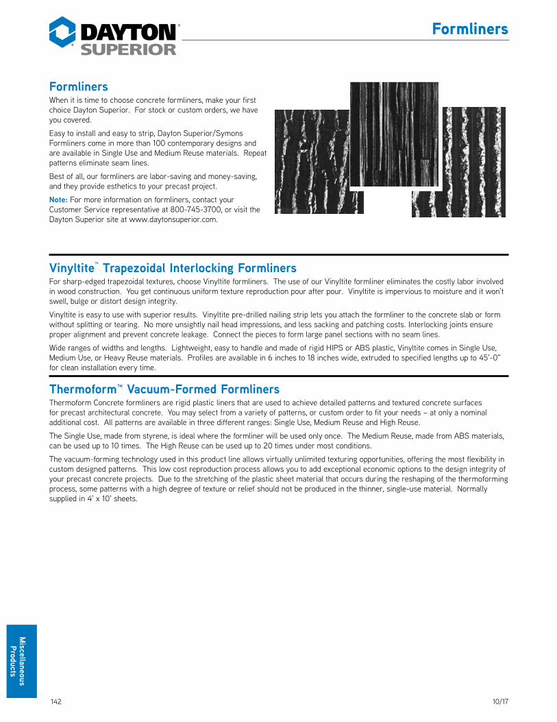
142 10/17
Miscellaneous Products
FormlinersWhen it is time to choose concrete formliners, make your first choice Dayton Superior. For stock or custom orders, we have you covered. DS_Formliners
Easy to install and easy to strip, Dayton Superior/Symons Formliners come in more than 100 contemporary designs and are available in Single Use and Medium Reuse materials. Repeat patterns eliminate seam lines.
Best of all, our formliners are labor-saving and money-saving, and they provide esthetics to your precast project.
Note: For more information on formliners, contact your Customer Service representative at 800-745-3700, or visit the Dayton Superior site at www.daytonsuperior.com.
Vinyltite™ Trapezoidal Interlocking FormlinersFor sharp-edged trapezoidal textures, choose Vinyltite formliners. The use of our Vinyltite formliner eliminates the costly labor involved in wood construction. You get continuous uniform texture reproduction pour after pour. Vinyltite is impervious to moisture and it won’t swell, bulge or distort design integrity. DS_Vinyltite
Vinyltite is easy to use with superior results. Vinyltite pre-drilled nailing strip lets you attach the formliner to the concrete slab or form without splitting or tearing. No more unsightly nail head impressions, and less sacking and patching costs. Interlocking joints ensure proper alignment and prevent concrete leakage. Connect the pieces to form large panel sections with no seam lines.
Wide ranges of widths and lengths. Lightweight, easy to handle and made of rigid HIPS or ABS plastic, Vinyltite comes in Single Use, Medium Use, or Heavy Reuse materials. Profiles are available in 6 inches to 18 inches wide, extruded to specified lengths up to 45'-0" for clean installation every time.
Thermoform™ Vacuum-Formed FormlinersThermoform Concrete formliners are rigid plastic liners that are used to achieve detailed patterns and textured concrete surfaces for precast architectural concrete. You may select from a variety of patterns, or custom order to fit your needs – at only a nominal additional cost. All patterns are available in three different ranges: Single Use, Medium Reuse and High Reuse. DS_Thermoform
The Single Use, made from styrene, is ideal where the formliner will be used only once. The Medium Reuse, made from ABS materials, can be used up to 10 times. The High Reuse can be used up to 20 times under most conditions.
The vacuum-forming technology used in this product line allows virtually unlimited texturing opportunities, offering the most flexibility in custom designed patterns. This low cost reproduction process allows you to add exceptional economic options to the design integrity of your precast concrete projects. Due to the stretching of the plastic sheet material that occurs during the reshaping of the thermoforming process, some patterns with a high degree of texture or relief should not be produced in the thinner, single-use material. Normally supplied in 4' x 10' sheets.
Formliners

14310/17
Mis
cella
neou
s Pr
oduc
ts
Chemicals
FORM RELEASE AGENTSOIL BASED
Clean Strip™ Ultra J3Form ReleaseClean Strip Ultra J3 is a premium, low odor, ready to- use, low V.O.C. chemically reactive form release ideal for architectural and precast concrete and for general forming applications. Clean Strip Ultra J3 works to ensure clean, positive release of plywood, fiberglass, aluminum, steel and other concrete forming materials. Clean Strip Ultra J3 prolongs the life of plywood forms, and acts to reduce rusting of steel forms. Properly applied, Clean Strip Ultra J3 is non-staining, reduces the number of surface air voids (bugholes) and will not interfere with the adhesion of subsequent coatings.
Clean Strip™ J1AForm ReleaseClean Strip J1A is a low V.O.C., ready-to-use, petroleum based, chemically reactive concrete form release that effectively prevents bonding of concrete to forms and formliners.
Clean Strip™ J100 VOCForm ReleaseClean Strip J100 VOC is a V.O.C. compliant in all areas of the U.S., ready-to-use, petroleum based, chemically reactive concrete form release that effectively prevents bonding of concrete to forms and formliners. Regular use of Clean Strip J100 VOC will increase the life of all forms. Clean Strip J100 is compliant with all US VOC regulations for Concrete Form Release agents including Federal EPA, OTC, LADCO, SCAQMD & CARB.
Magic Kote® Form ReleaseMagic Kote is a low V.O.C., ready-to-use, petroleum based, chemically neutral, diesel free concrete form release. Magic Kote is water insoluble and contains no waxes. Magic Kote effectively prevents bonding of concrete to forms and formliners. Regular use of Magic Kote will increase the life of all forms.
WATER BASEDClean Strip™ J1EFEarth Friendly® Form ReleaseClean Strip J1EF is an economical low V.O.C., concrete form release agent. Clean Strip J1EF works to ensure clean, positive release on plywood, fiberglass, aluminum, steel, urethane and other concrete forming materials and formliners. This product acts as a barrier to the adhesion of concrete while minimizing surface dusting. Properly applied, Clean Strip J1EF will not stain concrete or interfere with the adhesion of coatings. Clean Strip J1EF is compliant with all US VOC regulations for Concrete Form Release agents including Federal EPA, OTC, LADCO,SCAQMD & CARB.
CURING COMPOUNDSRESIN BASED
Clear Resin Cure J11WClear Resin Cure J11W is an all resin, dissipating water-based curing compound. Ready to use on freshly placed concrete surfaces. Complies with ASTM C-309.
BOND BREAKERS FOR CONCRETE-TO-CONCRETE RELEASE
WATER BASEDSure Lift™ J6WBWater-Based Bond BreakerSure Lift J6WB is a liquid, V.O.C. compliant, waterbased, reactive and membrane forming bond breaker for use in precast construction. Sure Lift J6WB is a special formula of polymers and propriety ingredients designed to provide clean, easy lifting of precast members.

144 10/17
Miscellaneous Products
Chemicals
SOLVENT BASEDSure Lift™ with Dye J6DBond BreakerSure Lift with Dye J6D is a reactive and membrane forming bond breaker for use in tilt wall construction. Sure Lift with Dye J6D is a special formula of polymers and propriety ingredients designed to provide clean, easy lifting of precast members. Sure Lift with Dye J6D has a fugitive dye for ease of visual inspection during application and is also available without the dye upon special request.
EVAPORATION REDUCERSAquaFilm™ Concentrate J74Evaporation RetardantAquaFilm Concentrate J74 is a proprietary emulsion of unique organic compounds designed to minimize moisture loss from fresh concrete. AquaFilm Concentrate J74 is economical as a concentrate and is diluted with potable water at a 9 to 1 ratio. As a water based polymer, AquaFilm Concentrate J74 is V.O.C. compliant and contains a blue fugitive dye for ease of visual inspection during application.
AquaFilm™ J74RTUEvaporation RetardantAquaFilm J74RTU is a ready-to-use proprietary emulsion of unique organic compounds designed to minimize moisture loss from fresh concrete. As a water based polymer, it is V.O.C. compliant. AquaFilm J74RTU contains a yellow fugitive dye.
EPOXY CONSTRUCTION ADHESIVESANCHORING GEL / PASTE
All Weather J51AWEpoxy Gel AnchorAll Weather J51 AW is a two component 100% solid, moisture tolerant, all weather epoxy acrylate hybrid anchoring gel that meets ASTM C 881 specification requirements. All Weather J51 AW is formulated to set up at room temperatures and down to temperatures
Sure Anchor™ J50Epoxy Gel AnchorSure Anchor J50 is a two component, 100% solids, moisture tolerant, high modulus epoxy gel adhesive that meets ASTM C-881 and AASHTO M-235.
Sure Anchor™ I J51Epoxy Gel AnchorSure Anchor I J51 is two component, moisture tolerant, 100% solids, high modulus, rapid setting epoxy gel adhesive that meets ASTM C-881 and AASHTO M-235.
MEDIUM VISCOSITY Sure Bond™ J58Epoxy AdhesiveSure Bond J58 is a 100% solids, two component, high modulus, medium viscosity, moisture tolerant structural epoxy adhesive that meets the requirements of ASTM C-881 and AASHTO M-235.
Sure Bond™ J58 LPLEpoxy AdhesiveSure Bond J58 LPL is a 100% solids, two component, high modulus, medium viscosity, moisture tolerant, long open time structural epoxy adhesive meeting the requirements of ASTM C-881 and AASHTO M-235.
LATEX BONDING AGENTS / ADMIXTURESAcrylic Bonding Agent J40Bonding AgentA ready-to-use, non-reemulsifiable acrylic admixture and bonding agent designed to improve the adhesion and durability of concrete, masonry, terrazzo and portland cement-sand mixes to horizontal and vertical concrete and other surfaces.
PVA Bonding Agent J41Bonding AgentPVA Bonding Agent J41 is a concentrated reemulsifiable/ rewettable polyvinyl acetate (PVA) emulsion for use as a bonding agent for application on concrete, cement board or masonry prior to installing patches, mortars, stucco and plaster.
NON-SHRINK GROUTSCEMENT BASED GROUTS
1107 Advantage Grout™Cement Based Grout1107 Advantage Grout is a non-shrink, non-corrosive, non-metallic cementitious grout. 1107 Advantage Grout is designed to provide a controlled, positive expansion to ensure an excellent bearing area. 1107 Advantage Grout can be mixed from a fluid to a stiff plastic consistency.
Dri Pak Precast GroutCement Based GroutDri Pak Precast Grout is a non-shrink, non-corrosive, non-metallic cementitious grout. Dri Pak Precast Grout is designed to provide a controlled, positive expansion to ensure an excellent bearing area. Dri Pak Precast Grout can be mixed from a stiff to a flowable consistency.

14510/17
Mis
cella
neou
s Pr
oduc
ts
Chemicals
Sleeve-Lock® GroutNon-Shrink GroutSleeve-Lock Grout is a specially formulated cement based, non-metallic , non-shrink grout designed for the grouting of the Dayton Superior D410 Sleeve Lock® Grout Sleeve. The grout, used in conjunction with the sleeve, makes up a unique fully integrated system from Dayton Superior Corporation.
GENERAL USE REPAIR MORTARS
Polyfast™ FSRepair MortarPolyfast FS is a is shrinkage compensated, high strength mortar containing portland cement, special polymers and additives to provide an outstanding strength gain along with a fast set. Polyfast FS is a single component trowelable material formulated for vertical, overhead and horizontal repairs.
Recrete™ 5 MinuteRepair MortarRecrete 5 Minute is a general purpose cement based concrete repair and patching material. Recrete 5 Minute is specially formulated to provide a very fast setting repair mortar with excellent workability. Recrete 5 Minute can be used for repair and patching of vertical, overhead and horizontal areas subject to light traffic both interior and exterior.
Recrete™ 20 MinuteRepair MortarRecrete 20 Minute is a general purpose cement based concrete repair and patching material. Recrete 20 Minute is specially formulated to provide a fast setting repair mortar with excellent workability. Recrete 20 Minute can be used for repair and patching of vertical, overhead and horizontal areas subject to light traffic both interior and exterior.
Recrete™ Light 20 MinuteRepair MortarRecrete Light 20 Minute is a general purpose cement based concrete repair and patching material that dries to a light gray color. Recrete Light 20 Minute is specially formulated to provide a fast setting repair mortar with excellent workability. Recrete Light 20 Minute can be used for repair and patching of vertical, overhead and horizontal areas subject to light traffic both interior and exterior.
Anchor AllAnchoring CementA fast-setting, non-shrink anchoring cement with controlled expansion. Pourable and fast setting, Anchor All provides a durable high strength anchor for interior and exterior applications.
Waterstop™Hydraulic Cement Repair MortarWaterstop is a non-corrosive, non-rusting, extremely fast setting hydraulic cement compound for plugging and stopping active water leaks in concrete structures or masonry surfaces. When mixed with water to a thick consistency and hand formed into a plug, it will stop active leaks even under water.
Dayton Superior Chemicals Dedicated SupportDayton Superior quality construction chemicals are backed by experts in the construction chemicals field. They are dedicated to timely assistance in the selection and application of any Dayton Superior chemical product.
Customer service can be obtained from any Dayton Superior Service Center. For in depth product information such as Technical Data Sheets, specifications, Safety Data Sheets, visit the Dayton Superior web site at www.daytonsuperior.com.
Dayton Superior has experience, dedication, commitment and a comprehensive line of quality chemicals for the precast concrete industry. These necessary ingredients make Dayton Superior a valued partner to the precast/prestressed producer in their efforts to meet the inherent demands of the precast/ prestressed concrete industry.
Call 866-329-8724 for technical support, or for the contact information of your local Dayton Superior salesperson.

146 10/17
Miscellaneous Products
Other Products
Rustications, Chamfers and CoversRustications, chamfers and cover products manufactured by Victory Bear provide innovative solutions to the designer and the contractor. These products provide significant labor savings in the installation of the rustications and chamfers along with eliminating much of the building finish problems which occur with wood products. And now these products can be found at a Dayton Superior distribution center near you.
SLAB SAVER2' PVC Edge pieces installed in the bottom of wall panels used to protect floors during panel erection, eliminating damage to the floor slab during panel erection. VB_SlabSaver
RUSTICATION¾" x 45 degree PVC rustication in widths of 2.25", 2.5", 3.5", 5.5", 8.0" and 11.5". These have the patented Flex Edge Seal, insuring a tight joint with the concrete slab and these utilize the Victory Bear Base Clip for easy installation. 1/2" x 60 degree low profile rustication also available. VB_Rustication
SNAP RUSTICATION¾" Triangular PVC rustication which opens to allow easy installation and then snaps shut to prevent concrete seepage. VB_SnapRustication
BULKHEAD¾" PVC bulkhead chamfer providing chamfer on both sides of the bulkhead. This product is used with both ¾" plywood and 2x materials. It features both the patented Flex Edge Seal and utilizes the Base Clip to secure the product to the floor slab. VB_Bulkhead
BULLNOSEPVC Single Bullnose chamfers provide the radius edges when the designer desires a different effect from the traditional triangular building edges. VB_Bullnose
RADIUS CORNER6" PVC Radius Corner provides a distinct radius at a fraction of the cost. VB_RadiusCorner
CHAMFERS¾" x 45 degree PVC chamfers in both single and double chamfer versions. This product utilizes the patented Flex Edge Seal and is attached to the floor slab with adhesives or traditional nails or screws. VB_Chamfers
CHAMFERS – LOW PROFILE1/2" x 60 degree PVC chamfers in both single and double chamfer versions. This product utilizes the patented Flex Edge Seal and is attached to the floor slab with adhesives or traditional nails or screws. VB_ChamfersLowProfile
DRIP EDGE CHAMFERUse ¾" x 45° PVC drip edge chamfer for use where doors, windows, dock doors and archways require both a chamfer and drip edge. This product utilizes the patented Flex Edge Seal and is attached to the floor slab with adhesives or traditional nails or screws. VB_DripEdgeChamfer
RECESSED WINDOW SYSTEMA unique utilization of several of the above products with a recessed window chamfer to add a classic detail for doors and windows in the concrete wall panels. VB_RecessedWindowSystem
JOINT COVERPVC Joint Covers provide the building owner an attractive cover for the joints inside of the building. Joint Covers will fit into panel joints between ¼" and 1" gaps. VB_JointCover
SAW CUT COVERPVC Saw Cut Cover temporarily seals the floor slab joints with a unique low profile design VB_SawCutCover.
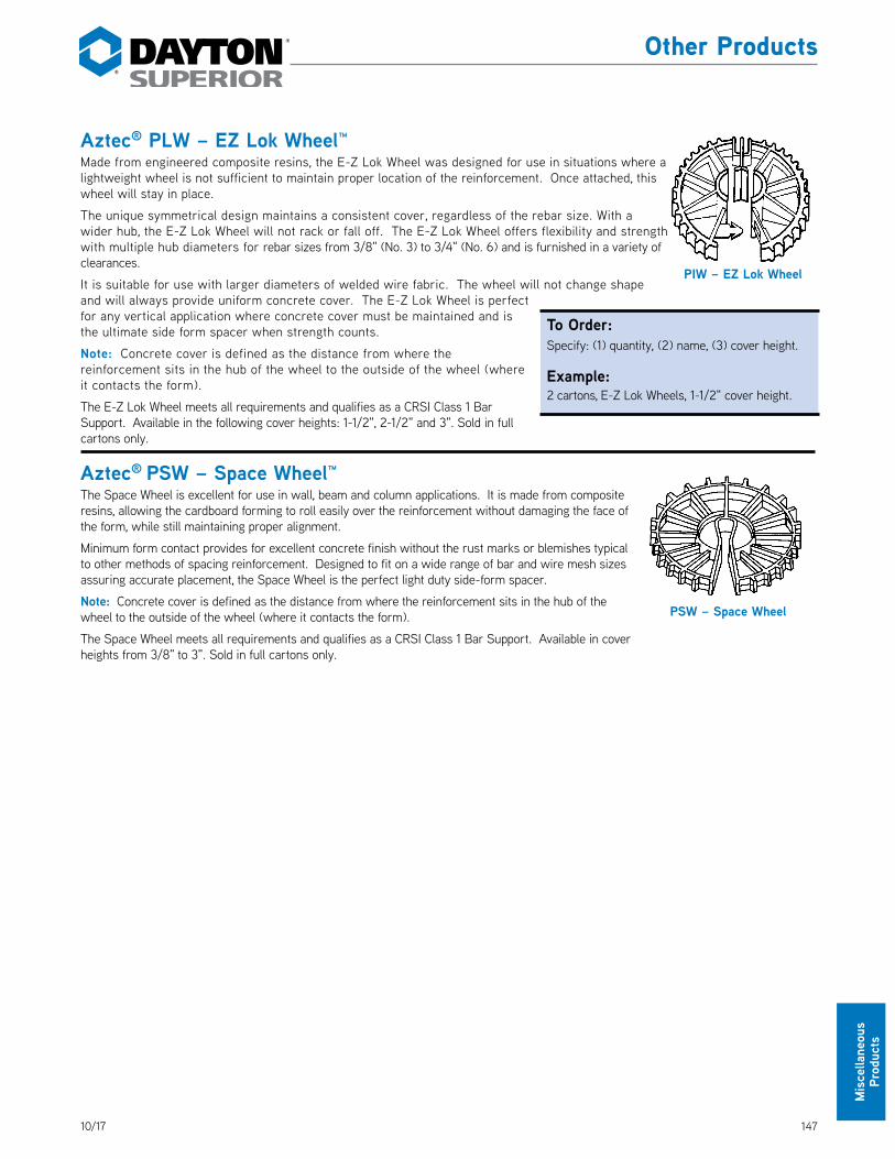
14710/17
Mis
cella
neou
s Pr
oduc
ts
Aztec® PLW – EZ Lok Wheel™Made from engineered composite resins, the E-Z Lok Wheel was designed for use in situations where a lightweight wheel is not sufficient to maintain proper location of the reinforcement. Once attached, this wheel will stay in place. DS_PLW
The unique symmetrical design maintains a consistent cover, regardless of the rebar size. With a wider hub, the E-Z Lok Wheel will not rack or fall off. The E-Z Lok Wheel offers flexibility and strength with multiple hub diameters for rebar sizes from 3/8" (No. 3) to 3/4" (No. 6) and is furnished in a variety of clearances.
It is suitable for use with larger diameters of welded wire fabric. The wheel will not change shape and will always provide uniform concrete cover. The E-Z Lok Wheel is perfect for any vertical application where concrete cover must be maintained and is the ultimate side form spacer when strength counts.
Note: Concrete cover is defined as the distance from where the reinforcement sits in the hub of the wheel to the outside of the wheel (where it contacts the form).
The E-Z Lok Wheel meets all requirements and qualifies as a CRSI Class 1 Bar Support. Available in the following cover heights: 1-1/2", 2-1/2" and 3". Sold in full cartons only.
Aztec® PSW – Space Wheel™The Space Wheel is excellent for use in wall, beam and column applications. It is made from composite resins, allowing the cardboard forming to roll easily over the reinforcement without damaging the face of the form, while still maintaining proper alignment. DS_PSW
Minimum form contact provides for excellent concrete finish without the rust marks or blemishes typical to other methods of spacing reinforcement. Designed to fit on a wide range of bar and wire mesh sizes assuring accurate placement, the Space Wheel is the perfect light duty side-form spacer.
Note: Concrete cover is defined as the distance from where the reinforcement sits in the hub of the wheel to the outside of the wheel (where it contacts the form).
The Space Wheel meets all requirements and qualifies as a CRSI Class 1 Bar Support. Available in cover heights from 3/8" to 3". Sold in full cartons only.
PIW – EZ Lok Wheel
PSW – Space Wheel
Other Products
To Order:Specify: (1) quantity, (2) name, (3) cover height.
Example:2 cartons, E-Z Lok Wheels, 1-1/2" cover height.

148 10/17
Miscellaneous Products
Aztec® Bar ChairBar Chairs are used to support widely spaced, light steel in slab and deck construction. Each bar chair provides two cover heights that are clearly marked for field identification. Available in 3/4" to 2-1/2" cover heights and sold in full cartons only. DS_TowerBarChair
Aztec® Tower High ChairTower High Chairs are strong, preassembled supports for heavy applications. The design features staple-down feet, quick-tie hooks and two service heights. The two service heights allow reduced inventory and save warehouse space. Tower High Chairs are well suited for applications where multiple layers of steel are required. Chairs are available in cover heights from 2-3/4" to 10" and sold in full cartons only.
An optional Sand Plate (sold separately) is available for use on grade. DS_TowerHighChair
Aztec® E-Z Chair® E-Z Chairs are designed for superior strength and stability. They are well suited for tilt-up, precast and poured-in-place slab applications. They are available in 3/4" to 6" cover heights for rebar sizes up to #11. E-Z Chairs are sold in full cartons only.
An Optional Sand Plate is available for use on grade or in sandwich panel applications. DS_EZChair
Aztec® Castle Chair™Castle Chairs are uniquely designed with a wide base ring to provide stability on poorly compacted or expansive soils. Each Castle Chair offers two cover heights to allow for variation in grading. They are strong enough to carry the weight of ironworkers and concrete finishers, but will not damage moisture protection membranes. Castle Chairs are available in 1-1/2" to 4-1/4" cover heights and are sold in full cartons only. DS_CastleChair
PBC Bar Chair
PTC Tower High Chair
PTSCB Tower Chair Sand Plate
PCC Castle Chair
PEZ E-Z Chair PSP Sand Plate
Other Products
To Order:Specify: (1) quantity, (2) name, (3) Product Code, (4) cover height.
Example:4 cartons (700), 121271, E-Z Chairs, 4" cover.
To Order:Specify: (1) quantity, (2) name, (3) Product Code, (4) cover height.
Example:2 cartons (700), 122837, Castle Chairs, 2-1/2" to 2-3/4" cover.
To Order:Specify: (1) quantity, (2) name, (3) Product Code, (4) cover height.
Example:2 cartons (300), 121295, Tower High Chairs, 6" cover.
To Order:Specify: (1) quantity, (2) name, (3) Product Code, (4) cover height.
Example:2 cartons (900), 121288, Bar Chairs, 1-3/4" to 2" cover.

14910/17
Mis
cella
neou
s Pr
oduc
ts
Aztec® X-ChairX-Chairs are light weight, inexpensive chairs used for supporting rebar and wire mesh in horizontal applications. The X-Chair’s novel design produces a very strong support with minimal surface contact. X-Chairs are available in 1/2" to 2" cover heights and are sold in full cartons only. DS_XChair
Aztec® E-Z Lok™ Slab BolsterE-Z Lok Slab Bolster provides a strong, stable support and spacer for rebar in slab or wall applications. The E-Z Lok Slab Bolster can be used in individual 32" sections or the sections can be snapped together to satisfy any job-required length. E-Z Lok Slab Bolster is available in 3/4" to 3" cover heights and is sold in full cartons only. DS_EZLokSlabBolster
Aztec® PSBU Strongback SBU™PSBU supports top layer in Double Mat application, rebar or wire mesh, slabs, heavy duty on-grade, corrugated decking, side-form spacer-below-grade applications only, precast. Cover heights from 1" to 3-1/4" (1/4" increments). DS_PSBUStrongbackSBU
• Designed for use with epoxy-coated/FRP/stainless steel/galvanized rebar• Intended for use in corrosive environments• Spans corrugations in elevated deck applications• Suitable for use on vapor barriers or insulating foam• No overlap required• Manufactured in 30" lengths in standard boxes• Special packaging available in 5' or 10' sections, bundled and palletized • Strong as metal SBU
Panel PadsPanel Pads were created especially for use in the precast industry for stacking. When placed on top of the precast concrete elements, the Panel Pads will support the weight of additional elements without damage to either element. The unique bubble design allows the precast materials to cure uniformly. Panel Pads are manufactured to snap in half. The 2-1/2" x 5-1/2" pads are spaced around the precast unit. DS_PanelPad
PSB E-Z LOK Slab Bolster
PXC X-Chair
PPP - Panel Pads
1/2" Thick
5-1/2"
PSBU StrongBack SBU
Other Products
To Order:Specify: (1) quantity, (2) name, (3) cover height.
Example:1 carton (1100), 122834, X-Chairs, 2" cover.
To Order:Specify: (1) quantity, (2) name, (3) cover height.
Example:2 cartons (300), 78066, E-Z LOK Slab Bolster, 2" cover.
To Order:Specify: (1) quantity, (2) name, (3) name.
Example:20 Boxes, 2-1/2" Cover Panel Pads.
To Order:Specify: (1) quantity, (2) name.
Example:200, Panel Pads.
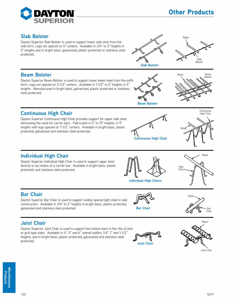
150 10/17
Miscellaneous Products
Slab BolsterDayton Superior Slab Bolster is used to support lower slab steel from the slab form. Legs are spaced on 5" centers. Available in 3/4" to 3" heights in 5" lengths and in bright basic, galvanized, plastic protected or stainless steel protected. DS_SlabBolster
Beam BolsterDayton Superior Beam Bolster is used to support lower beam steel from the soffit form. Legs are spaced on 2-1/2" centers. Available in 1-1/2" to 5" heights in 5" lengths. Manufactured in bright basic, galvanized, plastic protected or stainless steel protected. DS_BeamBolster
Continuous High ChairDayton Superior Continuous High Chair provides support for upper slab steel, eliminating the need for carrier bars. Fabricated in 2" to 15" heights, in 5" lengths with legs spaced on 7-1/2" centers. Available in bright basic, plastic protected, galvanized and stainless steel protected. DS_ContinuousHighChair
Individual High Chair Dayton Superior Individual High Chair is used to support upper steel directly or by means of a carrier bar. Available in bright basic, plastic protected, and stainless steel protected. DS_IndividualHighChair
Bar ChairDayton Superior Bar Chair is used to support widely spaced light steel in slab construction. Available in 3/4" to 2" heights in bright basic, plastic protected, galvanized and stainless steel protected. DS_BarChair
Joist ChairDayton Superior Joist Chair is used to support two bottom bars in the ribs of joist or grid type slabs. Available in 4", 5" and 6" overall widths; 1/4", 1" and 1-1/2" heights; and in bright basic, plastic protected, galvanized and stainless steel protected. DS_JoistChair
Bar Chair
Rebar
Bar Chair
Joist Chair
Rebar
Joist Chair
Slab Bolster
Rebar
Slab Bolster
Beam Bolster
Rebar Beam Bolster
Continuous High Chair
Rebar
Continuous High Chair
Individual High Chairs
Rebar
High Chair
Other Products

15110/17
Mis
cella
neou
s Pr
oduc
ts
Other Products
K50 Void Retention InsertThe Dayton Superior K50 Void Retention Insert’s primary function is to conveniently position and firmly hold in place void tubes used in precast slabs, piles, box beams, etc. Use of the K50 inserts eliminates the possibility of the voids floating to the surface when concrete is placed in the forms. The K50 insert is injection-molded from nonreactive, noncorrosive thermoplastic and is designed to fit 10"- and 12"-diameter voids. DS_K50
H13 Round Void Hold DownThe Dayton Superior Round Void Hold Down is a one piece unit that completely encompasses the round void tube and is attached to your form using a standard 3/4" coil bolt. This prevents movement in any direction of the void tube. Maintained in stock for 10" and 12" OD Diameter Void Tubes, other sizes available. DS_H13
K50 Void Retention Insert
9-1/4"
2-3/4"
3"
2"
To Order:Specify: (1) quantity, (2) name.
Example: 200, K50 Void Retention Inserts.
To Order:Specify: (1) quantity, (2) dia of tube (4) plain or galvanized finish.
Example: 200, H13 12" Round Hold Down, Plain.

152 10/17
Miscellaneous Products
P80 Shim StripsDayton Superior P80 Shim Strips assure accurate placing and leveling of tilt-up panels and other architectural and structural components because they: DS_P80
• are made in convenient thicknesses, lengths and widths allowing precise leveling and alignment.• permit field changes in load bearing requirements with stock on hand.• are less expensive and safer than steel. They have extreme stability and eliminate rust-stained concrete and spalling.• are size scored for convenience of application. Prevent waste – material can be readily picked up and stored in the open for future
use.• will not fracture under load.• are available from stock in thicknesses of 1/16", 1/8" and 1/4" and lengths of 3" and 4". The widths of 3" x 24" are scored every 3"
and the widths of 4" x 24" are scored every 2". This allows for easy snap off as needed. Additional sizes available on request.• are impervious to liquids, ground chemicals, alkalis and microorganisms. The continuing performance characteristics are stable and
predictable.• will not rust, rot or leach when exposed to wet surfaces and have no odor.• arrive at the job site in precise thicknesses and lengths.• eliminate the need for saws, hand tools or cutters. A definite saving in time, labor and money is realized. The strips are easily applied
and lie flat.• decrease damage potential to the adjacent concrete components. Point projection of aggregate is absorbed without fracture or effect
on the load-bearing characteristics.
Engineering Data: The pertinent physical properties of Dayton Superior plastic shims are presented as follows:
• Compressive strength of 8,000 to 9,000 psi with no fracture, even at 26,000 psi.• Classed as slow-burning with no toxic fumes.• Negligible cold flow characteristics; i.e., less than 1% at 1,000 psi and 73˚F. for
10,000 hours.• Coefficient of linear expansion is 3 to 5 x 10⁻⁵ inches/inch/˚C
P81 ShimpakDayton Superior shimming material is an engineered multipolymer plastic specifically formulated for use by the construction industry. DS_P81
This material provides an optimum combination of physical properties for a shim in applications where high compressive strength and load bearing are important. It facilitates the placement of tilt-up structural, and other architectural, members.
• These pre-assembled packages of heavy duty shims are designed for large precast units.
• Shimpaks are very advantageous in precise placing and leveling of large panels.• Their use eliminates time consuming correction of elastomeric drift and makes
alignment safer and easier.• Popular sizes are 4" x 6" and 4" x 4" packs which are 1-1/16" thick. Shimpaks
are made up of shims in the following thickness sequence: one 1/16", three 1/4" and two 1/8". Tilt-up panels can be levelled within 1/16" by removing or adding one or more elements.
• Shimpaks are held together with a resilient band for easy removal or addition of elements.
• Alternate sizes available on request.
Foundation or other structural member.
P81 Shimpaks
Precast Element
Other Products
To Order:Specify: (1) quantity, (2) name, (3) length.
Example:300, P80 Shim Strips, 1/4" x 4".
To Order:Specify: (1) quantity, (2) name, (3) size.
Example:200 packs, P81 Shimpaks, 4" x 6".

15310/17
Mis
cella
neou
s Pr
oduc
ts
P82 Bearing Strips• Designed for use with prestressed concrete plank between the
plank and any surface, such as poured or precast concrete, steel or masonry. DS_P82
• Absorb projecting aggregate stress preventing plank or sill damage without effect on the load bearing characteristics.
• Allow faster erection because of easier positioning.• Nonslip surface ensures positive placement.• Permit thermal motion and point rotation without an elastomeric
layer.• Test data available on request.
Thicknesses of 1/8" and 1/4" in stock. Lengths of 48" in stock. Widths of 24", scored at 2" intervals for easy snap off and flexibility in use. Alternate sizes or scorings available on request.
P83 Horseshoe Spacers• No staining, no rust, no corrosion, even with aluminum.• Less expensive than steel–no plating required.• Lightweight and precise–easy to handle and transport.• Cut to size or prescored for easy on-site snap-off.
Available with holes, other slot sizes or different width, length or thickness on special order. Minimum order 100 pcs. of each thickness and size.
P83 Horseshoe Spacer Selection TableWidth Length Thickness Slot Size
2" 3" 1/16", 1/8" or 1/4" 13/16" x 2-7/16"
3" 4" 1/16", 1/8" or 1/4" 13/16" x 2-15/16"
P84 Korolath Core Plugs• Core plugs designed for manufacturers of prestressed hollow core plugs DS_P84• Lightweight, easy-to-insert, block off grout flow• Exclusive “wall” taper design of plastic plugs assures tight fit• Plug numbers refer to the diameter of the core holes, not the thickness of the plank
Number Diameter Plugs/Carton
400 4" 1,000
600 6" 2,000
800 8" 1,000
P82 Bearing StripsAvailable in full cartons only. Each carton holds 300 2" x 48" strips.
Width
Length
Slot Size
Thickness
P83 Horseshoe Spacer
P84 Korolath Plugs
Other Products
To Order:Specify: (1) quantity, (2) name, (3) size.
Example:2 cartons, P82 Bearing Strips, 1/4" x 48".
To Order:Specify: (1) quantity, (2) name, (3) size.
Example:2 cartons, P84 Core Plugs, No. 600.
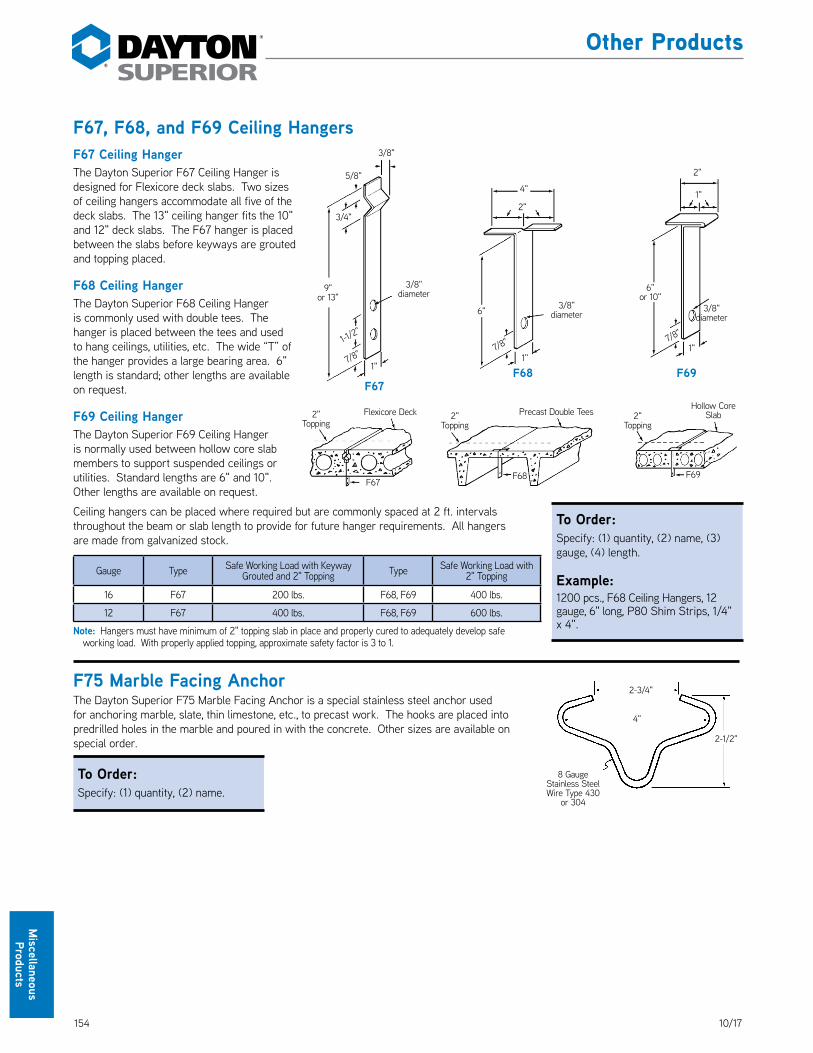
154 10/17
Miscellaneous Products
F67, F68, and F69 Ceiling HangersF67 Ceiling HangerThe Dayton Superior F67 Ceiling Hanger is designed for Flexicore deck slabs. Two sizes of ceiling hangers accommodate all five of the deck slabs. The 13" ceiling hanger fits the 10" and 12" deck slabs. The F67 hanger is placed between the slabs before keyways are grouted and topping placed. DS_F67_F68_F69
F68 Ceiling HangerThe Dayton Superior F68 Ceiling Hanger is commonly used with double tees. The hanger is placed between the tees and used to hang ceilings, utilities, etc. The wide “T” of the hanger provides a large bearing area. 6" length is standard; other lengths are available on request.
F69 Ceiling HangerThe Dayton Superior F69 Ceiling Hanger is normally used between hollow core slab members to support suspended ceilings or utilities. Standard lengths are 6" and 10". Other lengths are available on request.
Ceiling hangers can be placed where required but are commonly spaced at 2 ft. intervals throughout the beam or slab length to provide for future hanger requirements. All hangers are made from galvanized stock.
Gauge Type Safe Working Load with Keyway Grouted and 2" Topping Type Safe Working Load with
2" Topping
16 F67 200 lbs. F68, F69 400 lbs.
12 F67 400 lbs. F68, F69 600 lbs.
Note: Hangers must have minimum of 2" topping slab in place and properly cured to adequately develop safe working load. With properly applied topping, approximate safety factor is 3 to 1.
F75 Marble Facing AnchorThe Dayton Superior F75 Marble Facing Anchor is a special stainless steel anchor used for anchoring marble, slate, thin limestone, etc., to precast work. The hooks are placed into predrilled holes in the marble and poured in with the concrete. Other sizes are available on special order. DS_F75
To Order:Specify: (1) quantity, (2) name.
1"
3/8" diameter
F68
4"
2" Topping
Precast Double Tees
F68
6"
2"
7/8" 1"
F69
3/8" diameter
2"
1"
Hollow Core Slab2"
Topping
F69
6" or 10"
7/8"
3/8"
3/8" diameter
1"
F67
2" Topping
Flexicore Deck
F67
9" or 13"
5/8"
1-1/2"
3/4"
7/8"
2-3/4"
4"
8 Gauge Stainless Steel Wire Type 430
or 304
2-1/2"
Other Products
To Order:Specify: (1) quantity, (2) name, (3) gauge, (4) length.
Example:1200 pcs., F68 Ceiling Hangers, 12 gauge, 6" long, P80 Shim Strips, 1/4" x 4".

15510/17
Mis
cella
neou
s Pr
oduc
ts
Cushion-Lock® Reglet Type B4• PVC Construction• No Reaction with Concrete• No Caulking — now or ever• 100% Leakproof• No Exposed Metal Nails• 10 ft. LengthsThe advanced design of this reglet offers a number of exclusive features, yet the in-place cost is actually lower than that of conventional reglets. The completely enclosed design of the B4 Reglet prevents any concrete from entering during pouring operation. Just prior to the installation of the counter-flashing, the integral protective strip is pulled off, exposing a clean recess ready to receive the counterflashing… and no caulking is needed as the snap-in and lock-in patented features of this reglet provides a 100% leakproof joint, yet future removal of the counterflashing for inspection or repair of roofing material is possible. DS_CushionLock
Recommended gauges for counterflashing are .020" to .032" maximum for aluminum or zinc; 26 to 24 gauge for steel; 16 or 20 oz. for copper. Fast and easy installation of counterflashing can be made under all weather conditions.
Each order for type B4 Reglet is supplied with sufficient connector plugs and installation instructions with a full-size template pattern for counterflashing.
SpecificationsSpecify Dayton Superior Type B4 Reglets and counterflashing in sheet metal section of specs. Sample specification: “Use Cushion-Lock Type B4 Reglet of PVC (polyvinyl chloride) plastic ASTM-D1784-81, Class 14333D, as manufactured by Dayton Superior Corporation.
Connector PlugsConnector Plugs, made from flexible PVC 3" long are supplied with B4 Reglet. They serve both to connect lengths of Reglet together, with adjoining openings perfectly aligned, as well as a plug to keep concrete from entering reglet at ends. Plugs may be easily removed to installation of counterflashing. DS_ConnectorPlugs
InstallationCounterflashing snaps and locks in position. Fastener is concealed and protected by counterflashing. DO NOT rivet or fasten ends of counterflashing together.
A. Reglet is fastened to form at 12" O.C. with 6 or 8 penny double-headed nail.B. Concave design provides spring-like action to hold reglet tightly against form lumber,
when nail is driven home.C. Reglet in position, after form is stripped, but prior to removal or integral
protective strip.D. Lip acts as waterstop to prevent any possible water seepage behind reglet.
This Strip is pulled off just prior to installation of
counterflashing. Easily removed.
Made of PVC (polyvinyl chloride) Plastic /060" thick, highest quality, ASTM-D1784-81 Class 14333D.
Other Products
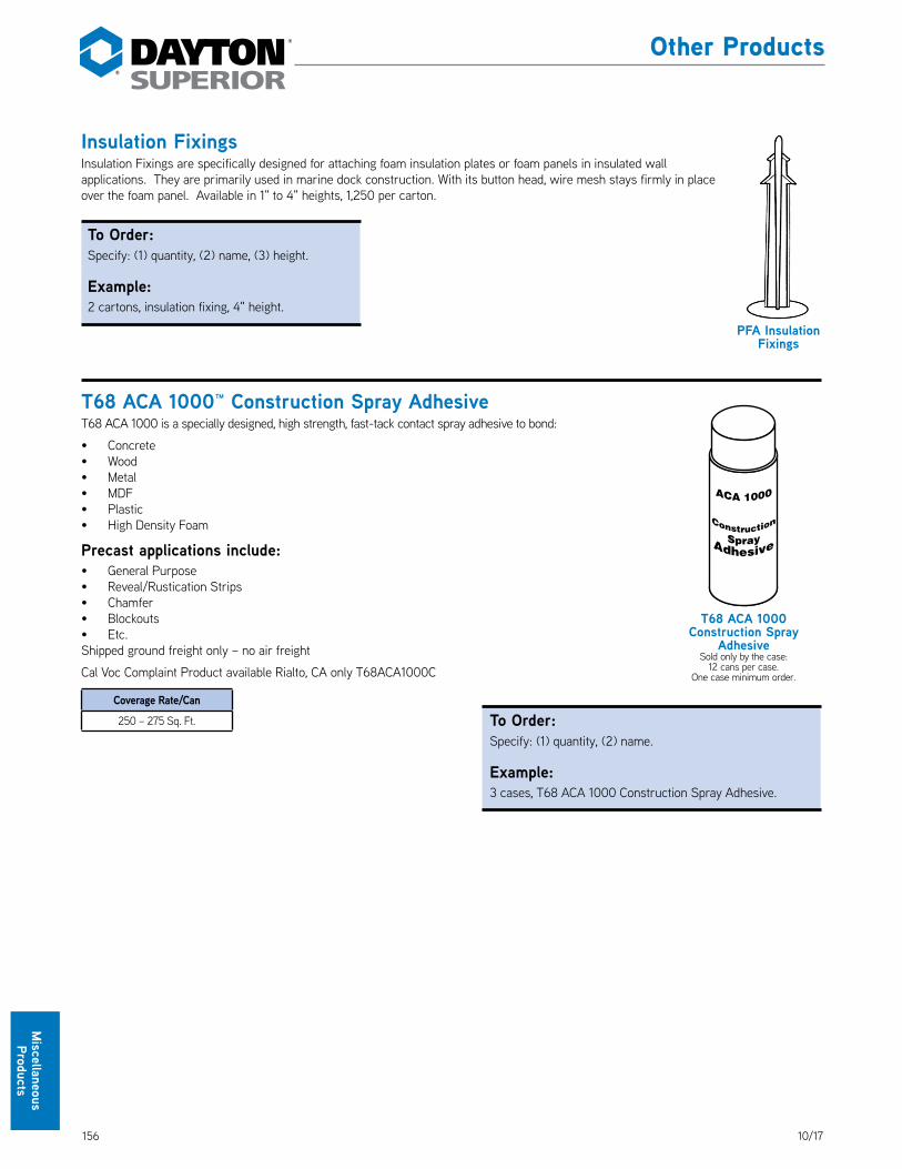
156 10/17
Miscellaneous Products
Insulation FixingsInsulation Fixings are specifically designed for attaching foam insulation plates or foam panels in insulated wall applications. They are primarily used in marine dock construction. With its button head, wire mesh stays firmly in place over the foam panel. Available in 1" to 4" heights, 1,250 per carton. DS_InsulationFixings
T68 ACA 1000™ Construction Spray AdhesiveT68 ACA 1000 is a specially designed, high strength, fast-tack contact spray adhesive to bond: DS_T68
• Concrete• Wood• Metal• MDF• Plastic• High Density Foam
Precast applications include:• General Purpose• Reveal/Rustication Strips• Chamfer• Blockouts• Etc.Shipped ground freight only – no air freight
Cal Voc Complaint Product available Rialto, CA only T68ACA1000C
Coverage Rate/Can
250 – 275 Sq. Ft.
PFA Insulation Fixings
T68 ACA 1000 Construction Spray
AdhesiveSold only by the case:
12 cans per case. One case minimum order.
Other Products
To Order:Specify: (1) quantity, (2) name, (3) height.
Example:2 cartons, insulation fixing, 4" height.
To Order:Specify: (1) quantity, (2) name.
Example:3 cases, T68 ACA 1000 Construction Spray Adhesive.
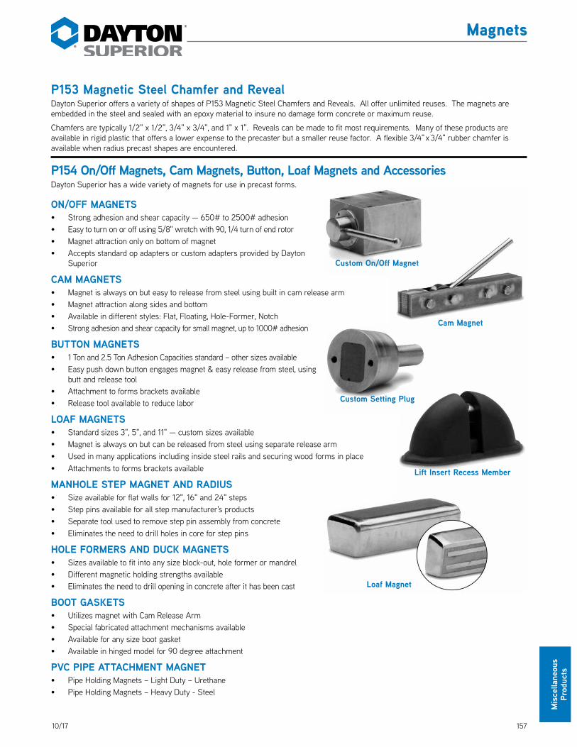
15710/17
Mis
cella
neou
s Pr
oduc
ts
P153 Magnetic Steel Chamfer and RevealDayton Superior offers a variety of shapes of P153 Magnetic Steel Chamfers and Reveals. All offer unlimited reuses. The magnets are embedded in the steel and sealed with an epoxy material to insure no damage form concrete or maximum reuse.
Chamfers are typically 1/2" x 1/2", 3/4" x 3/4", and 1" x 1". Reveals can be made to fit most requirements. Many of these products are available in rigid plastic that offers a lower expense to the precaster but a smaller reuse factor. A flexible 3/4" x 3/4" rubber chamfer is available when radius precast shapes are encountered. DS_P153
P154 On/Off Magnets, Cam Magnets, Button, Loaf Magnets and AccessoriesDayton Superior has a wide variety of magnets for use in precast forms. DS_P154
ON/OFF MAGNETS• Strong adhesion and shear capacity — 650# to 2500# adhesion• Easy to turn on or off using 5/8" wretch with 90, 1/4 turn of end rotor• Magnet attraction only on bottom of magnet• Accepts standard op adapters or custom adapters provided by Dayton
Superior
CAM MAGNETS• Magnet is always on but easy to release from steel using built in cam release arm• Magnet attraction along sides and bottom• Available in different styles: Flat, Floating, Hole-Former, Notch• Strong adhesion and shear capacity for small magnet, up to 1000# adhesion
BUTTON MAGNETS• 1 Ton and 2.5 Ton Adhesion Capacities standard – other sizes available• Easy push down button engages magnet & easy release from steel, using
butt and release tool• Attachment to forms brackets available• Release tool available to reduce labor
LOAF MAGNETS• Standard sizes 3", 5", and 11" — custom sizes available• Magnet is always on but can be released from steel using separate release arm • Used in many applications including inside steel rails and securing wood forms in place• Attachments to forms brackets available
MANHOLE STEP MAGNET AND RADIUS• Size available for flat walls for 12", 16" and 24" steps• Step pins available for all step manufacturer's products • Separate tool used to remove step pin assembly from concrete• Eliminates the need to drill holes in core for step pins
HOLE FORMERS AND DUCK MAGNETS• Sizes available to fit into any size block-out, hole former or mandrel• Different magnetic holding strengths available• Eliminates the need to drill opening in concrete after it has been cast
BOOT GASKETS• Utilizes magnet with Cam Release Arm• Special fabricated attachment mechanisms available• Available for any size boot gasket• Available in hinged model for 90 degree attachment
PVC PIPE ATTACHMENT MAGNET• Pipe Holding Magnets – Light Duty – Urethane• Pipe Holding Magnets – Heavy Duty - Steel
Magnets
Custom On/Off Magnet
Cam Magnet
Custom Setting Plug
Lift Insert Recess Member
Loaf Magnet

158 10/17
Notes and Sketches

15910/17
Index
1107 Advantage Grout ...................................................... 144ACA 1000 ...........................................................................156Accubrace Total Bracing System ....................................138Acrylic Bonding Agent J40 ............................................. 144Admixtures ........................................................................ 144All Weather J51AW ........................................................... 144Anchor All ...........................................................................145AquaFilm Concentrate J74 ............................................. 144AquaFilm J74RTU ............................................................ 144Aztec Bar Chair ................................................................ 148Aztec Castle Chair ............................................................ 148Aztec E-Z Chair ................................................................ 148Aztec E-Z Lok Slab Bolster ..............................................149Aztec EZ Lok Wheel ..........................................................147Aztec Space Wheel ...........................................................147Aztec Strongback ..............................................................149Aztec Tower High Chair .................................................. 148Aztec X-Chair .....................................................................149B1 83B1A.......................................................................................135B2 .........................................................................................83B4 ............................................................................... 135, 155B5.........................................................................................135B7 .........................................................................................135B8.........................................................................................135B9.........................................................................................135B10 .......................................................................................135B11 .................................................................................84, 135B12 ................................................................................84, 135B13 ................................................................................84, 135B14 ................................................................................85, 135B15 .......................................................................................135B16 ................................................................................86, 135B17 ........................................................................................86B17A ....................................................................................135B18 ................................................................................ 87, 135B21R23S .............................................................................139B25 .......................................................................................84B27R36S ............................................................................139B32R24S ............................................................................139B33 .......................................................................................88B33R22S ............................................................................139Bar Chair .................................................................... 148, 150Bar Lock Coupler ............................................................... 116Beam Bolster ..................................................................... 150Bearing Strips ....................................................................153Block Wall Lifting Anchor .................................................. 76Bond Breakers ...................................................................143Brace Length ......................................................................135Braces .................................................................................138Brace Safe Working Loads ...............................................135Cap Plug ............................................................................. 103Cast-In-Place Brace Anchor Loading ............................. 141Castle Chair ....................................................................... 148Ceiling Hangers ..................................................................154Chamfers ........................................................................... 146Clean Strip J1A ..................................................................143Clean Strip J1EF ................................................................143Clean Strip J100 VOC .......................................................143Clean Strip Ultra J3 ...........................................................143Clear Resin Cure J11W ......................................................143Coil-Anchor with Tang ..................................................... 140Coil Bolt ................................................................................85Coil Nut .................................................................................84Coil Rod ................................................................................84Coil Ties Used as Inserts ...................................................83Connecting Systems Nylon Threaded Inserts ............... 110Connector Plugs ................................................................155Construction Spray Adhesive ..........................................156Continuous High Chair ..................................................... 150Corewall Edge and Corner Details .................................. 121Corewall Nut Type Slotted Insert ............................. 117, 118Corewall Slotted Insert II ................................................. 120Corewall Slotted Strap Anchor ........................................ 119Corewall Strap Anchor ..................................................... 119Corewall Strap Type Slotted Insert .......................... 117, 119
Corewall Threaded Strap Anchor ................................... 119Countersunk Screw............................................................ 37Curing Compounds ............................................................143Cushion-Lock Reglet .........................................................155D108A...................................................................................111D410 .................................................................................... 113D487 .................................................................................... 114D490.................................................................................... 113D491..................................................................................... 114D492 .................................................................................... 114D493 .................................................................................... 114Delta Tie ..................................................................... 125, 129Disposable Setting Plugs ................................................... 79Double Flared Coil Loop Insert .................................. 86, 88Double Flared Loop Insert .................................................88Double Swivel Lifting Plate ...............................................98Dowel Bar Splicer .............................................................. 115Dri Pak Precast Grout ...................................................... 144Ductile Embed Insert ........................................................ 105Dur-O-Web ........................................................................ 122Edge Lifting Plate ................................................................99End Pickup Inserts .......................................................94, 96Epoxy Construction Adhesives ....................................... 144Evaporation reducers ....................................................... 144Expanded Coil Ferrule Inserts ........................................ 106Expanded Coil Inserts .........................................................91Eye Bolt ................................................................................89Eye Nut .................................................................................89E-Z Chair............................................................................ 148E-Z Lok Slab Bolster .........................................................149EZ Lok Wheel .....................................................................147F5 ......................................................................................... 101F11 .........................................................................................117F12 ........................................................................................117F42 ...................................................................................... 101F43 ..................................................................................... 102F44 ..................................................................................... 103F45 ..................................................................................... 103F47 ........................................................................................88F48 .......................................................................................89F49 .......................................................................................89F49A .....................................................................................89F50 ..................................................................................... 104F52 ..................................................................................... 104F53........................................................................................90F54 ..................................................................................... 105F56 ........................................................................................91F57 ...................................................................................... 106F58 ........................................................................................91F59...................................................................................... 106F60 ........................................................................................91F61 ...................................................................................... 106F62 ......................................................................................107F63........................................................................................92F64 ..................................................................................... 108F65 .......................................................................................92F65LF ................................................................................. 109F67 .......................................................................................154F68 ......................................................................................154F69 ......................................................................................154F72 ...................................................................................... 109F74 ...................................................................................... 109F75 .......................................................................................154Ferrule Loop Insert ........................................................... 108Flared Thin Slab Coil Insert ...............................................92Flared Thin Slab Ferrule Insert........................................107Flat Washer ..........................................................................84Fleet-Lift ...............................................................................39Fleet-Lift Cable Bail Ring Clutch ........................................41Fleet-Lift Cast Steel Recess Plug ..................................... 67Fleet-Lift Disposable Recess Plug....................................69Fleet-Lift Erection Anchor .................................................42Fleet-Lift Erection Anchor with 45˚ Head w/ Shear Plate .......58Fleet-Lift Erection Anchor w/ Shear Plate .....................44Fleet-Lift Erection Anchor w/ Shear Plate & Shear Pin ........46Fleet-Lift Flat Foot Anchor .................................................61
Fleet Lift Forged Erection Anchor ....................................48Fleet-Lift Forged Erection Anchor ...................................53Fleet-Lift Forged Erection Anchor w/ Shear Plate and
Secondary Shear Pin.....................................................50Fleet Lift Forged Erection Anchor w/ Sheer Plate ........49Fleet-Lift H-Anchor 2-Ton .................................................60Fleet-Lift Holding Plate ......................................................65Fleet-Lift Holding Rod ........................................................65Fleet-Lift L-Anchor .............................................................59Fleet-Lift Magnetic Plate .................................................... 74Fleet-Lift One Piece Magnetic Recess............................. 74Fleet-Lift Plate Anchor ......................................................62Fleet-Lift Reusable Recess Plug .......................................65Fleet-Lift Ring Clutch .........................................................40Fleet-Lift S-Anchor 6-Ton ..................................................61Fleet-Lift Sandwich Panel Erection Anchor ............ 54, 56Fleet-Lift Sandwich Panel Erection Anchor w/ Shear Plate ....54Fleet-Lift Sandwich Panel Reinforcing Bars .................. 57Fleet-Lift Shear Bar ...........................................................64Fleet-Lift T-Anchor .............................................................59Fleet-Lift Tension Bar ........................................................64Fleet-Lift Two-Hole Anchor ..............................................62Fleet-Lift Two-Hole Erection Anchor ...............................51Fleet-Lift Two-Hole Erection Anchor w/ Shear Plate....51Fleet Patch ........................................................................... 73Forged Foot Anchor ...........................................................63Formliners ......................................................................... 142Form Release .....................................................................143H13 ....................................................................................... 151Hanger Hook .......................................................................117Hanger Insert ......................................................................117Headed Dowel Bar Insert ..................................................111Heavy Coil Nut.....................................................................84Heavy Duty Long Pipe Brace ...........................................135Heavy Duty Regular Pipe Brace ......................................135Helical Ground Anchors ....................................................138HGA .....................................................................................138HGA Extension ...................................................................138Horseshoe Spacers ...........................................................153Individual High Chair ........................................................ 150Insert Locator Plugs ...........................................................98Insulation Fixings ...............................................................156J1A .......................................................................................143J1EF .....................................................................................143J3 .........................................................................................143J6D ..................................................................................... 144J6WB ...................................................................................143J11W.....................................................................................143J40 ..................................................................................... 144J41 ...................................................................................... 144J51 ...................................................................................... 144J51AW ................................................................................ 144J58...................................................................................... 144J58 LPL ............................................................................. 144J74 ...................................................................................... 144J74RTU .............................................................................. 144J100 VOC ............................................................................143Joist Chair .......................................................................... 150Jumbo Pipe Braces ...........................................................135K50 ...................................................................................... 151Korolath Core Plugs ...........................................................153Latex Bonding Agents ...................................................... 144Lifting Angle ........................................................................95Loop Ferrule Insert ............................................................ 101Magic Kote ..........................................................................143Magnetic OnePiece Swift Lift Recess ..............................38Magnetic Steel Chamfer and Reveal ...............................157Magnets ...............................................................................157“M” Anchor Shear Connector .......................................... 131Marble Facing Anchor .......................................................154Mounting Washers ..............................................................83Non-Shrink Grouts ........................................................... 144Nylon Threaded Inserts .................................................... 110One Piece Magnetic Utility Anchor Recess ....................80P1 93P9 ......................................................................................... 131
160 10/17
Index
P12D ................................................................................... 122P12G ................................................................................... 130P21 ........................................................................................90P24 ..................................................................................... 125P24XL .................................................................................129P25 .......................................................................................95P30 ............................................................................... 117, 118P31 ................................................................................ 117, 119P32 ...................................................................................... 119P33 ...................................................................................... 119P34 ...................................................................................... 119P37 ...................................................................................... 131P38 ..................................................................................... 120P50 ........................................................................................17P51 .........................................................................................19P52 ................................................................................ 22, 25P52W ....................................................................................25P53 .......................................................................................32P54 .......................................................................................34P56 .................................................................................23, 35P56PL ............................................................................23, 36P56R .....................................................................................35P57 .......................................................................................36P58 .......................................................................................36P59 .......................................................................................26P60 ....................................................................................... 33P61 ........................................................................................ 37P62 ....................................................................................... 37P63 ....................................................................................... 37P63PL .................................................................................. 37P64 ....................................................................................... 37P64PL .................................................................................. 37P66 .......................................................................................38P66PL ..................................................................................38P67PL...................................................................................38P68PL ..................................................................................38P69 .......................................................................................38P72 ....................................................................................... 76P73SL ....................................................................................77P75 ....................................................................................... 78P75C ..................................................................................... 78P75H..................................................................................... 78P76 ..................................................................................79, 81P76C ..................................................................................... 79P76D ..................................................................................... 79P76M ....................................................................................80P76P ..................................................................................... 79P80 ..................................................................................... 152P81 ...................................................................................... 152P82 ......................................................................................153P83 ......................................................................................153P84 ......................................................................................153P90 ...................................................................................... 110P91NC ....................................................................................41P91S .....................................................................................40P92AH..................................................................................58P92DP ..................................................................................46P92FE ..................................................................................48P92FEH ...............................................................................53P92FEW ...............................................................................49P92FEWDP .........................................................................50P92H .....................................................................................51P92HP ...................................................................................51P92P .....................................................................................44P92S.....................................................................................54P92SF ..................................................................................56P92SP ..................................................................................54P92T ...............................................................................42, 57P93 .......................................................................................59P94H ....................................................................................60P94S ......................................................................................61P95F ......................................................................................61P95P .....................................................................................62P96 .......................................................................................62P98S .....................................................................................64P98T .....................................................................................64
P99 .......................................................................................65P99C ..................................................................................... 67P99D.....................................................................................69P99P ..................................................................................... 73P100 .............................................................................. 65, 80P100M .................................................................................. 74P100MS ............................................................................... 74P101 ............................................................................... 65, 80P104F ................................................................................... 74P104S ...................................................................................38P104U ...................................................................................80P110 ......................................................................................82P140 .....................................................................................63P153 .....................................................................................157P154 .....................................................................................157Panel Pads ..........................................................................149PBC Tower Bar Chair ....................................................... 148PCC Castle Chair ............................................................... 148PEZ E-Z Chair ................................................................... 148Pipe Brace Extensions ......................................................134Plain Ferrule ...................................................................... 102Plastic Setting Bolt .............................................................95PLW .....................................................................................147Polyfast FS .........................................................................145Precast Sandwich Panel Tie ............................................ 131Prestress Strand Restraining Devices ............................133PSB E-Z LOK Slab Bolster ...............................................149PSBU ...................................................................................149PSBU StrongBack SBU ....................................................149PSP Sand Plate ................................................................ 148PSW .....................................................................................147PTC Tower High Chair ..................................................... 148PTSCB Tower Chair Sand Plate ..................................... 148PVA Bonding Agent J41 .................................................. 144PXC X-Chair .......................................................................149Recess Plugs .......................................................................23Recrete 5 Minute ...............................................................145Recrete 20 Minute .............................................................145Recrete Light 20 Minute ...................................................145Repair Mortars ...................................................................145Rocket/Kohler Ferrule Insert ........................................... 104Round Void Hold Down ..................................................... 151Rustications ....................................................................... 146Safety ...................................................................................... 1Setting Screw...................................................................... 74Shimpak ............................................................................. 152Shim Strips ........................................................................ 152Short Pipe Brace ...............................................................135Single Flared Coil Loop Insert ........................................... 87Single Pickup Insert ...........................................................93Single Use Void Former ..................................................... 79Slab Bolster ............................................................... 149, 150Sleeve-Lock ¾" SCH40 PVC .......................................... 114Sleeve-Lock Form Plug .................................................... 114Sleeve-Lock Grout ..................................................... 113, 145Sleeve-Lock Grout Sleeve ................................................ 113Sleeve-Lock Port Plug ...................................................... 114Sleeve-Lock Seal Plug ...................................................... 114Space Wheel .......................................................................147Straight Coil Loop Insert ....................................................86Strongback SBU ................................................................149Sure Anchor I J51 ............................................................ 144Sure Anchor J50 .............................................................. 144Sure Bond J58.................................................................. 144Sure Bond J58 LPL ......................................................... 144Sure Lift J6WB ..................................................................143Sure Lift with Dye J6D .................................................... 144Swift Lift ................................................................................17Swift Lift Anchor ......................................................... 22, 25Swift Lift Anchors for Edge Lifting ..................................25Swift Lift Eye Anchor .........................................................32Swift Lift Lifting Eye ............................................................19Swift Lift Magnetic Setting Plate ......................................38Swift Lift Narrow Recess Plug .........................................35Swift Lift Plus Holding Plate .............................................38Swift Lift Plus Holding Stud .............................................. 37
Swift Lift Plus Recess Plug ...............................................36Swift Lift Plus Stud Plate ..................................................38Swift Lift Plus Threaded Plate ..........................................38Swift Lift Plus Wing Nut .................................................... 37Swift Lift Round Recess Plug ...........................................35Swift Lift Rubber Ring ........................................................36Swift Lift Setting Plate ....................................................... 37Swift Lift Shear Bar ...........................................................26Swift Lift Smooth Wire Shear Bar ...................................26Swift Lift Steel Recess Plug ..............................................36Swift Lift Stud ..................................................................... 37Swift Lift Tapped Plate .......................................................38Swift Lift Tension Bar ........................................................ 33Swift Lift Throw-Away Recess Plug ................................34Swift Lift Universal Lifting Eye ..........................................17Swift Lift Wing Nut ............................................................. 37Swivel Lifting Plate .............................................................98T1 93T3 ..........................................................................................94T3A .......................................................................................94T4 ......................................................................................... 141T5A ...................................................................................... 141T6A ...................................................................................... 141T6S ...................................................................................... 141T7S .......................................................................................95T7ST .....................................................................................95T8 ..........................................................................................95T10 ........................................................................................96T11 .........................................................................................96T12 ........................................................................................98T13 ...................................................................................... 140T14 .......................................................................................134T14 Brace Length and Ultimate Loads ...........................135T15 .......................................................................................134T21 ........................................................................................98T26 .......................................................................................98T27 ........................................................................................99T68 ......................................................................................156T275 .....................................................................................63Thermoform ...................................................................... 142Thin Slab Coil Insert ...........................................................90Thin Slab Ferrule Insert ...........................................103, 104Thin Slab utility Anchor ......................................................77Threaded Insert.................................................................. 101Threaded Plastic Plug ...................................................... 109Threaded Setting Plug ..................................................... 109Tilt-Up Anchor ....................................................................63Tilt-Up Wall Braces ............................................................134Tower High Chair .............................................................. 148Transition Brace Connector .................................... 138, 140Two-Hole Cast Wall Plate ................................................ 140Type L Coil Insert ................................................................92Type LF Ferrule Insert ..................................................... 109Utility Anchor ....................................................................... 78Utility Anchor and Double Tee Anchor Setting Plug.......81Utility Anchor Cover/Patch ............................................... 79Utility Anchor Holding Plate ..............................................80Utility Anchor Holding Rod ................................................80Utility Anchor Magnetic Setting Plate ..............................80Utility Anchor Setting Plugs .............................................. 79Utility Anchor System ........................................................ 75Utility Anchor with Clip ...................................................... 78Vinyltite ............................................................................... 142Void Retention Insert ......................................................... 151Wall and Floor Plate Bracket ........................................... 140Waterstop ............................................................................145Welded Wire Girders ........................................................ 130Wire Rope Lifting System ..................................................82Wire Rope Loop...................................................................90X-Chair ................................................................................149

Improper Use of Concrete Accessories Can Cause Severe Injury or Death
Read, understand and follow the information and instructions in this publication before using any of the Dayton Superior concrete accessories displayed herein. When in
doubt about the proper use or installation of any Dayton Superior concrete accessory, immediately contact the nearest Dayton Superior Service Center or Technical Service
Department for clarification. See back cover for your nearest location.
Safety Information
Dayton Superior products are intended for use by trained, qualified and experienced workers only. Misuse or lack of supervision and/or inspection can contribute to serious accidents or deaths. Any application other than those shown in this publication should be carefully tested before use.
The user of Dayton Superior products must evaluate the product application, determine the safe working load and control all field condi-tions to prevent applications of loads in excess of a product’s safe working load. Safety factors shown in this publication are approximate minimum values. The data used to develop safe working loads for products displayed in this publication are a combination of actual testing and/or other industry sources. Recommended safe working loads given for the products in this publication must never be exceeded.
Worn Working PartsFor safety, concrete accessories must be properly used and maintained. Concrete accessories shown in this publication may be subject
to wear, overloading, corrosion, deformation, intentional alteration and other factors that may affect the device’s performance. All reusable accessories must be inspected regularly by the user to determine if they may be used at the rated safe working load or should be removed from service. The frequency of inspections depends upon factors such as (but not limited to) the amount of use, period of service and environment. It is the responsibility of the user to schedule accessory hardware inspections for wear and remove the hard-ware from service when wear is noted.
Design ChangesDayton Superior reserves the right to change product designs, rated loads and product dimensions at any time without prior notice.
Note: See Safety Notes and Safety Factor Information.
Shop or Field ModificationWelding can compromise a product’s safe working load value and cause hazardous situations. Knowledge of materials, heat treating and welding
procedures is necessary for proper welding. Consult a local welding supply dealer for assistance in determining required welding procedures.Since Dayton Superior cannot control workmanship or conditions in which modifications are done, Dayton Superior cannot be responsible for any
product altered in the field.
InterchangeabilityMany concrete accessory products that Dayton Superior manufactures are designed as part of a system. Dayton Superior strongly dis-
courages efforts to interchange products supplied by other manufacturers with components supplied by Dayton Superior. When used properly, and in accordance with published instructions, Dayton Superior products have proven to be among the best designed and safest in the industry. Used improperly or with incompatible components supplied by other manufacturers, Dayton Superior products or systems may be rendered unsafe.
InstallationWARNING1. Dayton Superior Corporation products shall be installed and used only as indicated on the Dayton Superior Corporation installation
guidelines and training materials.2. Dayton Superior Corporation products must never be used for a purpose other than the purpose for which they were designed or in a
manner that exceeds specific load ratings.3. All instructions are to be completely followed to ensure proper and safe installation and performance4. Any improper misuse, misapplication, installation, or other failure to follow Dayton Superior Corporation’s instruction may cause prod-
uct malfunction, property damage, serious bodily injury and death.
THE CUSTOMER IS RESPONSIBLE FOR THE FOLLOWING:1. Conformance to all governing codes2. Use of appropriate industry standard hardware3. The integrity of structures to which the products are attached, including their capability to safely accept the loads imposed, as evalu-
ated by a qualified engineer.
SAFETY INSTRUCTIONS:All governing codes and regulations and those required by the job site must be observed. Always use appropriate safety equipment

1125 Byers Road Miamisburg, OH 45342 937-866-0711888-977-9600
DS510/17
Copyright © 2017 Dayton Superior Corporation, All Rights Reserved.
BUILDING STRENGTH™