peltier-type chiller thermo-con - smc etech · series hec a peltier device (thermo-module) is a...
TRANSCRIPT
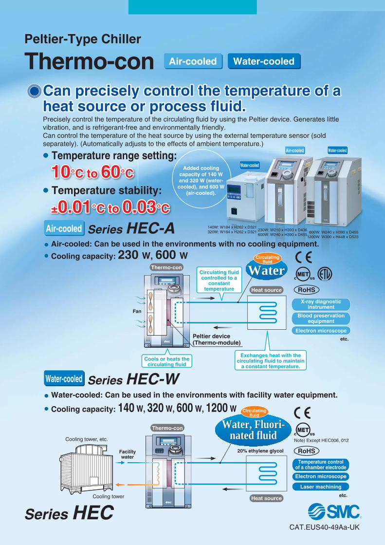
10°C to 60°C10°C to 60°C
±0.01°C to 0.03°C±0.01°C to 0.03°C
Cooling tower
Cooling tower, etc.
Can precisely control the temperature of a heat source or process fluid.Can precisely control the temperature of a heat source or process fluid.Precisely control the temperature of the circulating fluid by using the Peltier device. Generates little vibration, and is refrigerant-free and environmentally friendly.Can control the temperature of the heat source by using the external temperature sensor (sold separately). (Automatically adjusts to the effects of ambient temperature.)
Water-cooled
Air-cooled
Circulatingfluid
Series HEC-A
Series HEC-W
230W: W210 x H393 x D436600W: W240 x H390 x D455
600W: W240 x H390 x D4551200W: W300 x H448 x D523
� Air-cooled: Can be used in the environments with no cooling equipment. � Cooling capacity: 230 W, 600 W
� Water-cooled: Can be used in the environments with facility water equipment.
� Cooling capacity: 140 W, 320 W, 600 W, 1200 W
140W: W184 x H262 x D321320W: W184 x H262 x D321
Water-cooled
Water-cooledAir-cooled
Added coolingcapacity of 140 Wand 320 W (water-cooled), and 600 W
(air-cooled).
RoHS
RoHS
Note) Except HEC006, 012
� Temperature range setting:
� Temperature stability:
Peltier device(Thermo-module)
FanBlood preservation
equipment
X-ray diagnosticinstrument
Electron microscope
etc.
Thermo-con
Heat source
WaterWaterCirculating fluid controlled to a
constant temperature
Cools or heats the circulating fluid
Exchanges heat with the circulating fluid to maintain
a constant temperature.
Circulatingfluid
Electron microscope
Temperature controlof a chamber electrode
Laser machining
etc.
Facilitywater
20% ethylene glycol
Thermo-con
Heat source
Water, Fluori-nated fluid
Water, Fluori-nated fluid
Peltier-Type Chiller
Thermo-con Water-cooledAir-cooled
CAT.EUS40-49Aa-UK
Series HEC

Series HEC
A Peltier device (thermo-module) is a plate type element, inside which P-type semicon-ductors and N-type semiconductors are located alternately. If direct current is supplied to the Peltier device (thermo-module), heat is transferred inside the device, and one face generates heat and increases temperature while the other face absorbs heat and decreases temperature. Therefore, changing the direction of the current supplied to the Peltier device (thermo-module) can achieve heating and cooling operation. This method has a fast response and can shift quickly between heating and cooling, so temperature can be controlled very precisely.
� Compliant with safety standard for medical equipment IEC 60601-1 (Air-cooled/HEC002-A series)� Power supply: Applicable to 100 V to 240 V (Air-cooled/HEC-A series, Water-cooled/HEC001-W, HEC003-W)� Suitable to fluorinated fluids (FluorinertTM FC-3283, GALDEN® HT135) (Water-cooled/HEC006-W, HEC012-W)� Compatible with ethylene glycol 20% (Water-cooled/HEC001-W, HEC003-W)
Principle of Peltier Device (Thermo-module)
Learning Control Function (Temp. control by external temperature sensor)This function adjusts the fluid temperature to the set value with an automatic offset setting. Set the external temperature sensor at the circulating fluid inlet located just in front of the heat source, which allows the Thermo-con to sample the fluid temperature. This function is effective when automatically adjusting for heat exhaust from piping, etc. If the external temperature sensor is installed directly on the heat source, the learning control function may not work property due to large heat volume or large temperature difference. Be sure to install the sensor at the circulating fluid inlet.
Electron hole flow
Fan
Electron flow
Circulating fluid
CurrentHeat generation (heating)
Heat suction (cooling)
N P
DC power supply
Cooling
Electron hole flow
Fan
Electron flow
Circulating fluid
CurrentHeat suction (cooling)
Heat generation (heating)
N P
DC power supply
Heating
Heat suction (cooling)Cooling
Heat generation (heating)Heating
DC power supply
Facility waterCurrent Heat generation (heating)
Facility waterCurrent Heat suction (cooling)
DC power supply
Electron hole flow
Electron flow
Circulating fluid
N P Electron hole flow
Electron flow
Circulating fluid
N P
Water-cooled
Air-cooled
SeriesHEC-A
SeriesHEC-W
1

Peltier-Type Chiller/Thermo-con
Figure 2
Flow switch (option)
Noise filter
Circulating fluid supply port(Tank lid)
Circulating fluid
Level switch
Tank
Temperaturesensor
Pump
Peltier device(Thermo-module)
Fan
T
Power switch
PEPower supply &
Controller
Circulating fluiddrain port
Fan
Switching power supply
Controller
Circulating fluidOUT
IN
Target of temperature controlThermo-con
Example of circulating fluid piping
Heat exchanger
Heat exchanger(Cooling side)
Figure 1
Figure 1
T
Noise filter
Power switch
PEPower supply &
Controller
Fan
Switching power supply
Controller
Pump
Circulating fluid
Peltier device(Thermo-module)
Circulating fluid
OUT
IN
Heat exchanger
Heat exchanger
(Circulating fluid side)
(Circulating fluid side)
(Cooling side)
Supply tank
Level switch
Facility water Facility waterIN OUT
The Thermo-con is constructed as shown in Figure 1. It inter-poses a Peltier device (thermo-module) between the heat ex-changers for the circulating fluid and facility water and controls the pulse width of supply direct current to achieve the target outlet temperature of circulating fluid precisely.The circulating fluid returns to the tank, and is transferred by the pump which is built in the Thermo-con, and goes through the heat exchangers and internal sensors and out from the cir-culating fluid outlet.Figure 2 shows an example of circulating fluid piping. The circu-lating fluid is transferred at a constant temperature by the pump.
*1 Optional setting for the HEC001 and 003*2 Not built in the HEC001 and 003*3 Optional setting for the HEC001 and 003 only
Circulating fluid supply port(Tank lid)
Water-cooled
Water-cooled
Air-cooled
Air-cooled
Series HEC-A
Series HEC-W
Circulating ∗2
tank
Temperaturesensor ∗1
Circulatingfluid drain port
Flow switch ∗3
Construction and Principles
2
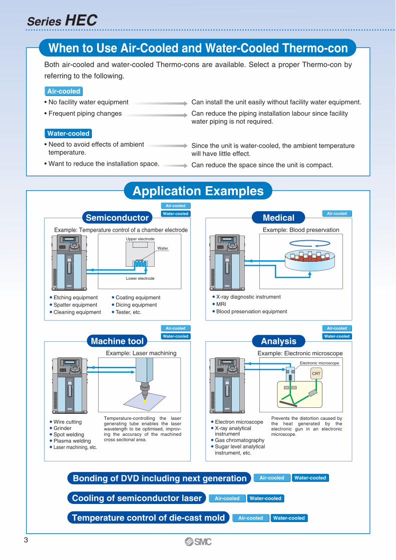
Application Examples
When to Use Air-Cooled and Water-Cooled Thermo-conBoth air-cooled and water-cooled Thermo-cons are available. Select a proper Thermo-con by
referring to the following.
will have little effect.
Water-cooled
Air-cooled
Water-cooled
Air-cooled
Water-cooled
Air-cooled
Water-cooled
Air-cooled
Air-cooled
Upper electrode
Lower electrode
SemiconductorExample: Blood preservation
MRI
Medical
Electronic microscope
CRT
Example: Electronic microscope
Electron microscope X-ray analytical
Gas chromatography
the heat generated by the
microscope.
AnalysisMachine toolExample: Laser machining
Grinder Spot welding Plasma welding
-
cross sectional area.
HEC
H
L
HEC
H
L
HEC
H
L
HEC
H
L
Bonding of DVD including next generation Water-cooledAir-cooled
Cooling of semiconductor laser Water-cooledAir-cooled
Temperature control of die-cast mold Water-cooledAir-cooled
Series HEC
3
Water-cooled
Series HEC-AAir-cooled
Series HEC-W
4
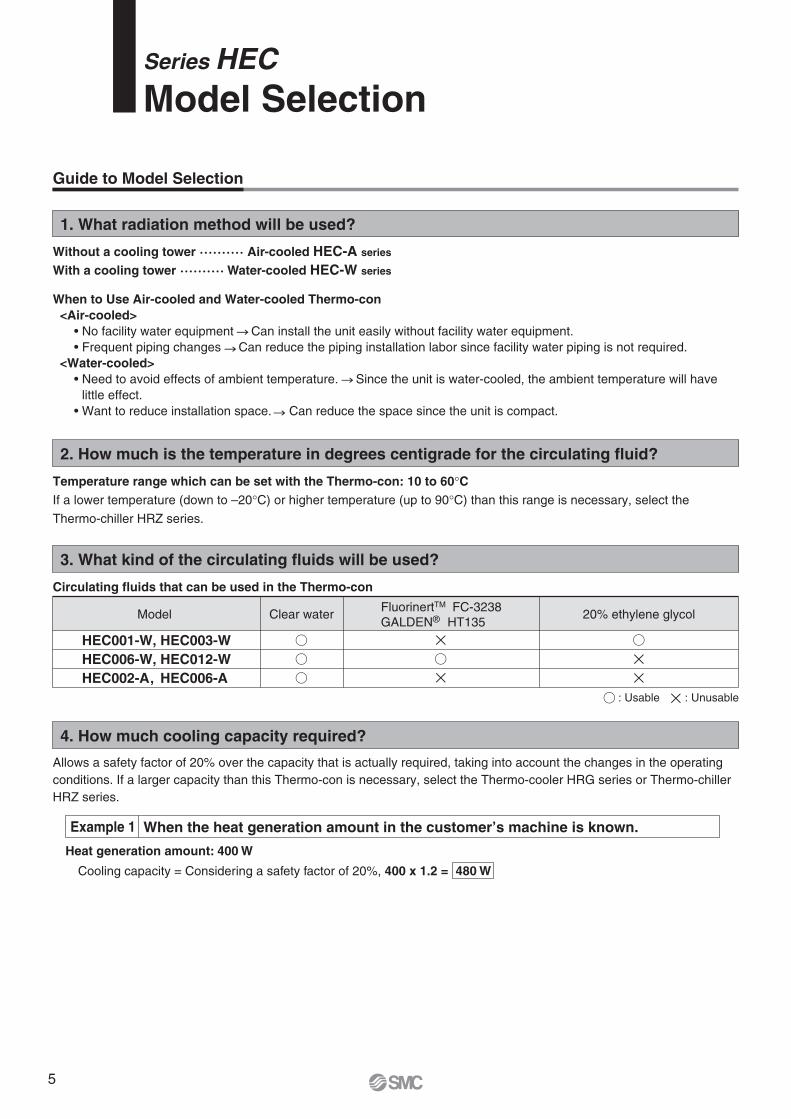
2. How much is the temperature in degrees centigrade for the circulating fluid?
Temperature range which can be set with the Thermo-con: 10 to 60°CIf a lower temperature (down to –20°C) or higher temperature (up to 90°C) than this range is necessary, select the
Thermo-chiller HRZ series.
1. What radiation method will be used?
Without a cooling tower ·········· Air-cooled HEC-A series
With a cooling tower ·········· Water-cooled HEC-W series
3. What kind of the circulating fluids will be used?
Allows a safety factor of 20% over the capacity that is actually required, taking into account the changes in the operating conditions. If a larger capacity than this Thermo-con is necessary, select the Thermo-cooler HRG series or Thermo-chiller HRZ series.
4. How much cooling capacity required?
Guide to Model Selection
Cooling capacity = Considering a safety factor of 20%, 400 x 1.2 = 480 W
Heat generation amount: 400 W
Example 1 When the heat generation amount in the customer’s machine is known.
Circulating fluids that can be used in the Thermo-con
Clear water FluorinertTM FC-3238GALDEN® HT135
20% ethylene glycolModel
HEC001-W, HEC003-WHEC006-W, HEC012-WHEC002-A, HEC006-A
: Usable : Unusable
When to Use Air-cooled and Water-cooled Thermo-con <Air-cooled>
<Water-cooled>
little effect.
Series HECModel Selection
5
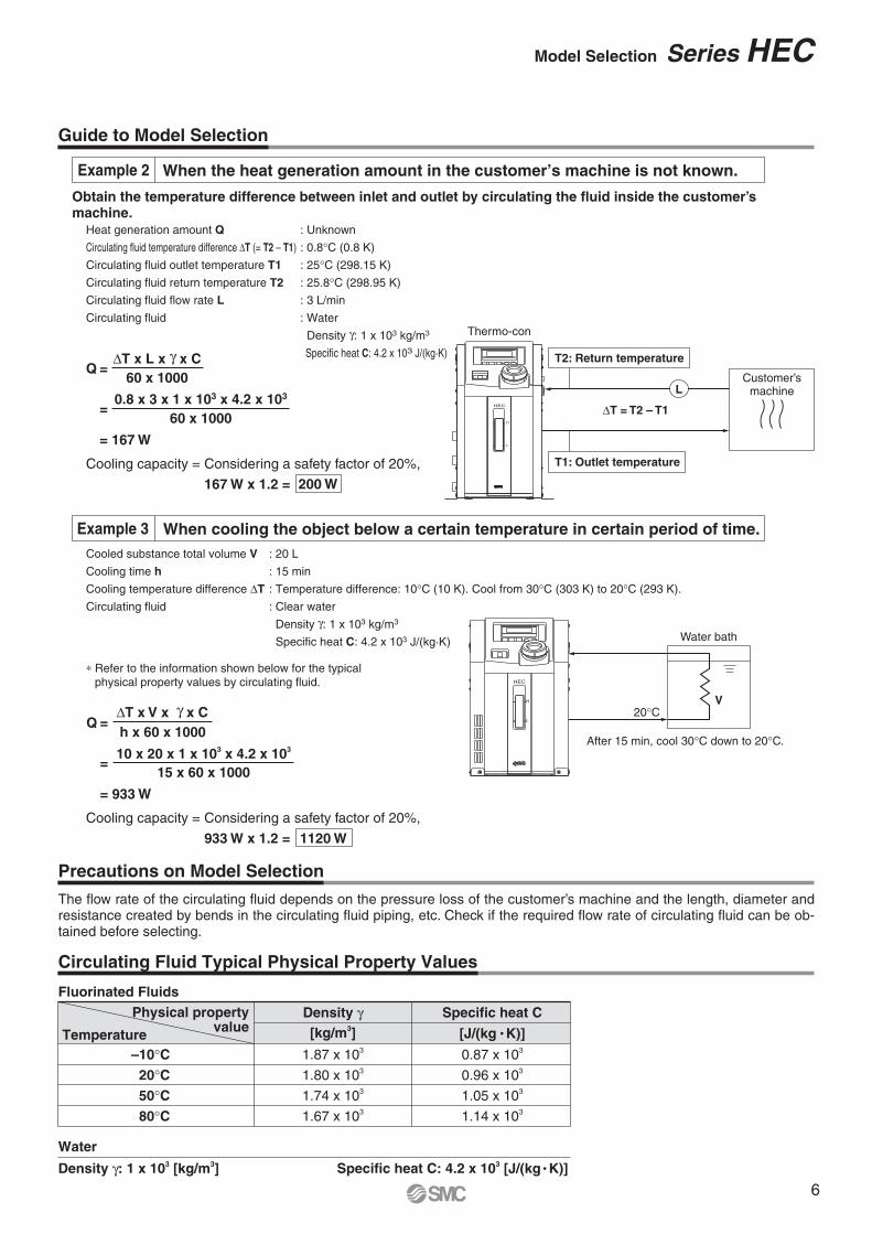
Obtain the temperature difference between inlet and outlet by circulating the fluid inside the customer’s machine.
Heat generation amount Q
Circulating fluid temperature difference ΔT (= T2 – T1)
Circulating fluid outlet temperature T1
Circulating fluid return temperature T2
Circulating fluid flow rate L
Circulating fluid
: Unknown
: 0.8°C (0.8 K)
: 25°C (298.15 K)
: 25.8°C (298.95 K)
: 3 L/min
: Water
Density γ: 1 x 10³ kg/m3
Specific heat C: 4.2 x 10³ J/(kg·K)Q =
ΔT x L x γ x C60 x 1000
0.8 x 3 x 1 x 103 x 4.2 x 103
60 x 1000
= 167 W
=
200 W
Thermo-con
Customer’smachine
T2: Return temperature
T1: Outlet temperature
L
ΔT = T2 – T1
L
H
HEC
Example 2 When the heat generation amount in the customer’s machine is not known.
Cooling capacity = Considering a safety factor of 20%,
167 W x 1.2 =
The flow rate of the circulating fluid depends on the pressure loss of the customer’s machine and the length, diameter and resistance created by bends in the circulating fluid piping, etc. Check if the required flow rate of circulating fluid can be ob-tained before selecting.
Precautions on Model Selection
Cooled substance total volume V
Cooling time h
Cooling temperature difference ΔT
Circulating fluid
∗ Refer to the information shown below for the typical physical property values by circulating fluid.
Cooling capacity = Considering a safety factor of 20%,
933 W x 1.2 = 1120 W
Q =ΔT x V x γ x Ch x 60 x 1000
=10 x 20 x 1 x 103 x 4.2 x 103
15 x 60 x 1000
= 933 W
Guide to Model Selection
: 20 L
: 15 min
: Temperature difference: 10°C (10 K). Cool from 30°C (303 K) to 20°C (293 K).
: Clear water
Density γ: 1 x 10³ kg/m3
Specific heat C: 4.2 x 10³ J/(kg·K) Water bath
V
After 15 min, cool 30°C down to 20°C.
20°C
HEC
H
L
Circulating Fluid Typical Physical Property Values
Fluorinated FluidsPhysical property
valueTemperature–10°C20°C50°C80°C
Density γ[kg/m3]
Specific heat C
[J/(kg K)]
0.87 x 10³
0.96 x 10³
1.05 x 10³
1.14 x 10³
1.87 x 10³
1.80 x 10³
1.74 x 10³
1.67 x 10³
Water
Density γ: 1 x 10³ [kg/m3] Specific heat C: 4.2 x 10³ [J/(kg K)]
Example 3 When cooling the object below a certain temperature in certain period of time.
Model Selection Series HEC
6
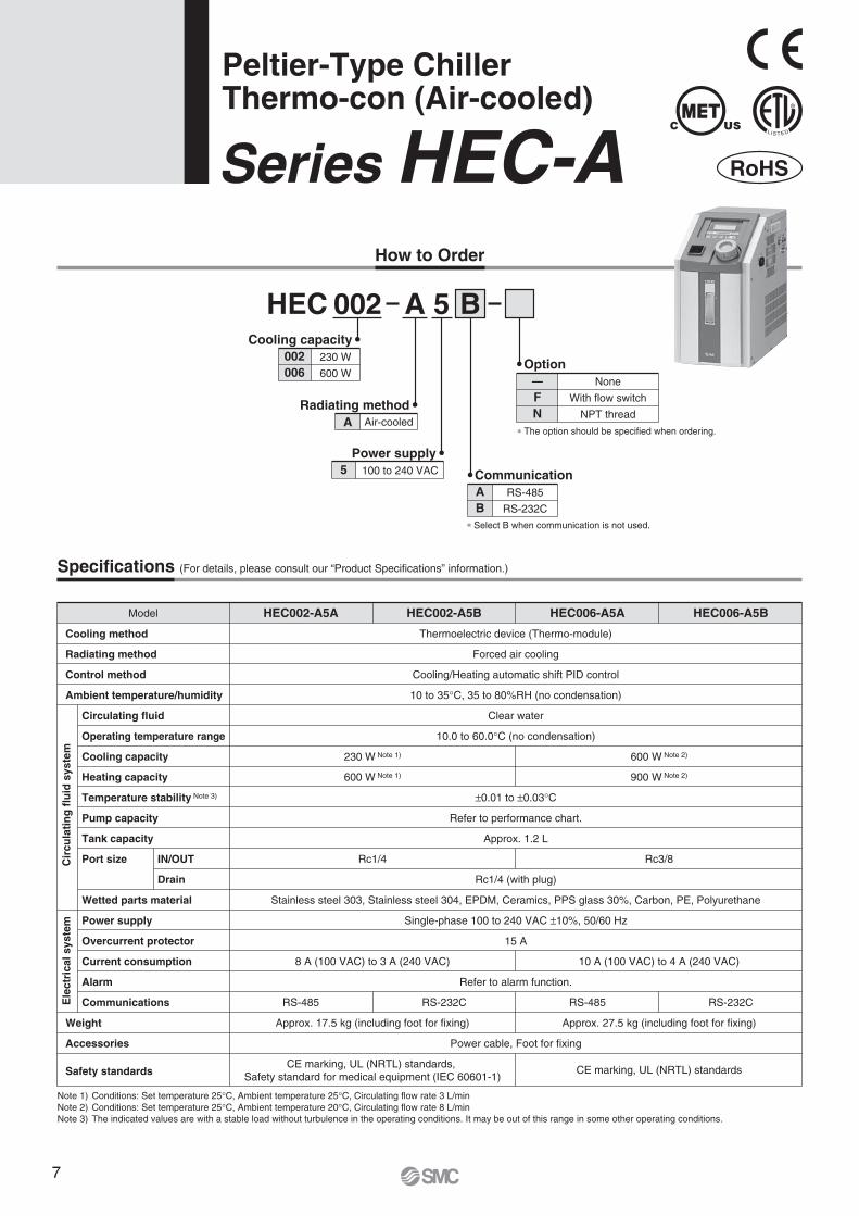
Peltier-Type ChillerThermo-con (Air-cooled)
Series HEC-AHow to Order
002 BHEC A 5
002006
230 W
600 W
Cooling capacity
A Air-cooled
Radiating method
5 100 to 240 VAC
Power supply
AB
RS-485
RS-232C
Communication
∗ The option should be specified when ordering.
∗ Select B when communication is not used.
—
FN
None
With flow switch
NPT thread
Option
Note 1) Conditions: Set temperature 25°C, Ambient temperature 25°C, Circulating flow rate 3 L/minNote 2) Conditions: Set temperature 25°C, Ambient temperature 20°C, Circulating flow rate 8 L/minNote 3) The indicated values are with a stable load without turbulence in the operating conditions. It may be out of this range in some other operating conditions.
Specifications (For details, please consult our “Product Specifications” information.)
Model HEC002-A5A HEC002-A5B HEC006-A5A HEC006-A5B
Cooling method
Radiating method
Control method
Ambient temperature/humidity
Circulating fluid
Operating temperature range
Cooling capacity
Heating capacity
Temperature stability Note 3)
Pump capacity
Tank capacity
Port size
Wetted parts material
Power supply
Overcurrent protector
Current consumption
Alarm
Communications
IN/OUT
Drain
Weight
Accessories
Safety standards
Thermoelectric device (Thermo-module)
Forced air cooling
Cooling/Heating automatic shift PID control
10 to 35°C, 35 to 80%RH (no condensation)
Clear water
10.0 to 60.0°C (no condensation)
±0.01 to ±0.03°C
Refer to performance chart.
Approx. 1.2 L
Rc1/4 (with plug)
Stainless steel 303, Stainless steel 304, EPDM, Ceramics, PPS glass 30%, Carbon, PE, Polyurethane
Single-phase 100 to 240 VAC ±10%, 50/60 Hz
15 A
Refer to alarm function.
Power cable, Foot for fixing
230 W Note 1)
600 W Note 1)
Rc1/4
8 A (100 VAC) to 3 A (240 VAC)
Approx. 17.5 kg (including foot for fixing)
600 W Note 2)
900 W Note 2)
Rc3/8
10 A (100 VAC) to 4 A (240 VAC)
Approx. 27.5 kg (including foot for fixing)
CE marking, UL (NRTL) standardsCE marking, UL (NRTL) standards, Safety standard for medical equipment (IEC 60601-1)
RS-485 RS-485RS-232C RS-232C
RoHS
Cir
cula
tin
g f
luid
sys
tem
Ele
ctri
cal s
yste
m
7
800
700
600
500
400
300
200
100
00 10 20 30 40 50 60 70
Circulating fluid temperature [°C]
Coo
ling
capa
city
[W]
1400
1200
1000
800
600
400
200
00 10 20 30 40 50 60 70
Circulating fluid temperature [°C]
Coo
ling
capa
city
[W]
1000
900
800
700
600
500
400
300
200
100
00 10 20 30 40 50 60 70
Circulating fluid temperature [°C]
Coo
ling
capa
city
[W]
2000
1800
1600
1400
1200
1000
800
600
400
200
00 10 20 30 40 50 60 70
Circulating fluid temperature [°C]
Coo
ling
capa
city
[W]
0.10
0.08
0.06
0.04
0.02
0.000 1 2 3 4
Circulating fluid flow rate [L/min]
Dis
char
ge p
ress
ure
[MP
a]
0.12
0.10
0.08
0.06
0.04
0.02
0.000 1 2 3 4 5 6 7 8 9 10
Circulating fluid flow rate [L/min]
Dis
char
ge p
ress
ure
[MP
a]
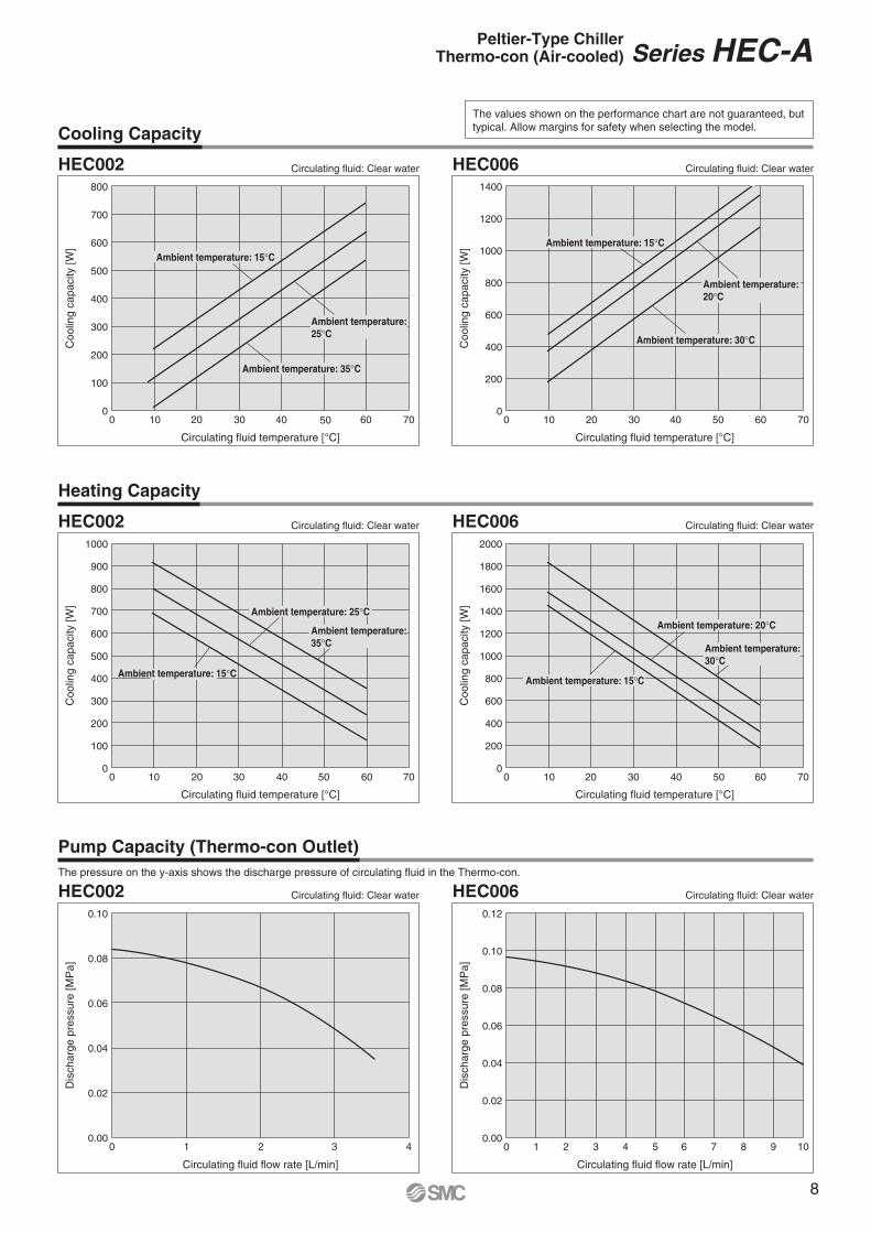
Cooling Capacity
Heating Capacity
Pump Capacity (Thermo-con Outlet)
The values shown on the performance chart are not guaranteed, but typical. Allow margins for safety when selecting the model.
Circulating fluid: Clear water
Ambient temperature: 15°C
Ambient temperature: 25°C
Ambient temperature: 35°C
Circulating fluid: Clear water
Circulating fluid: Clear water
The pressure on the y-axis shows the discharge pressure of circulating fluid in the Thermo-con.
Ambient temperature: 15°C
Ambient temperature: 35°C
Ambient temperature: 25°C
HEC002
HEC002
HEC002
HEC006
HEC006
HEC006
Circulating fluid: Clear water
Ambient temperature: 30°C
Ambient temperature: 15°C
Ambient temperature: 20°C
Circulating fluid: Clear water
Ambient temperature: 30°C
Ambient temperature: 20°C
Ambient temperature: 15°C
Circulating fluid: Clear water
Peltier-Type ChillerThermo-con (Air-cooled) Series HEC-A
8
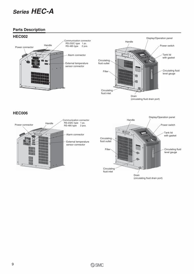
Parts Description
Power connectorHandle
Communication connector RS-232C type 1 pc. RS-485 type 2 pcs.
Alarm connector
External temperature sensor connector
HandleDisplay/Operation panel
Power switch
Tank lid with gasket
Circulating fluid level gauge
Circulating fluid outlet
Filter
Circulating fluid inlet
Drain(circulating fluid drain port)
HEC002
HEC006
Power connectorHandle
Communication connector RS-232C type 1 pc. RS-485 type 2 pcs.
Alarm connector
External temperature sensor connector
HandleDisplay/Operation panel
Power switch
Tank lid with gasket
Circulating fluid level gauge
Circulating fluid outlet
Filter
Circulating fluid inlet
Drain(circulating fluid drain port)
Series HEC-A
9
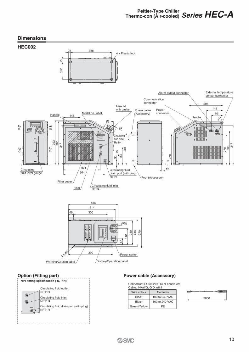
HEC002
Peltier-Type ChillerThermo-con (Air-cooled) Series HEC-A
Dimensions
P24
4171
54
man
ce d
ecre
ases
with
dus
t bui
ld u
p.Pl
ease
kee
p ai
r filte
r cle
an a
s pe
rfor-
Refe
r all r
epai
rd to
the
man
ufac
ture
r.
HAZA
RDO
US V
OLT
AGE
INSI
DE
WA
RN
ING
Cont
act m
ay c
ause
ele
ctric
sho
ck,o
rbur
n.Do
not
rem
ove
the
pane
l.
No u
ser s
ervic
eabl
e pa
rts in
side.
CA
UT
ION
ATSE
LRE
T
SM
CT
HE
RM
O-C
ON
270
240
210
142
57
R400
436
414
30046
4 x ø
5 390
Warning/Caution label Display/Operation panel
Power switch
ACEXT.SENSOR
RS-232C ALARM
347
300
270
270
298
145
101
51
External temperaturesensor connector
Handle
Alarm output connector
Communication connector
Power connector
L
H
HEC
Circulating fluid level gauge
Air
AirAir
Air
152
29
358214 x Plastic foot
3054524USC
MC
DETSIL
KETRETNI
CAN/CSA STD C22.2 NO.601.1CERTIFIED TO
UL STD 60601-1
ETL LISTED
CONFORMS TO
MAX CURRENT 8ASMC CORPORATION4-14-1,Sotokannda,Chiyoda-ku,Tokyo 101-0021,Japan
HEC002-A5B-F
HEADQUARTER
MODEL No.
INPUT VOLTAGESERIAL No. JT-****(JUN,2005)
OUT
IN
MADE IN JAPAN
THERMO-CON
DRAIN
34738
539
3
145
60
4928
115
797
30
321
364
Circulating fluid inletRc1/4
Tank lid with gasket
Circulating fluid outletRc1/4
Circulating fluid drain port (with plug)Rc1/4
Model no. labelHandle
Filter
Filter cover
12
Power cable(Accessory)
Foot (Accessory)
Power cable (Accessory)
Connector: IEC60320 C13 or equivalentCable: 14AWG, O.D. ø8.4
Wire colour
Black
Black
Green/Yellow
Contents
100 to 240 VAC
100 to 240 VAC
PE
2000
OUT
IN
DRAIN
Option (Fitting part)
Circulating fluid drain port (with plug)NPT1/4
Circulating fluid inletNPT1/4
Circulating fluid outletNPT1/4
NPT fitting specification (-N, -FN)
10
2000
Circulating fluid drain port (with plug)NPT1/4
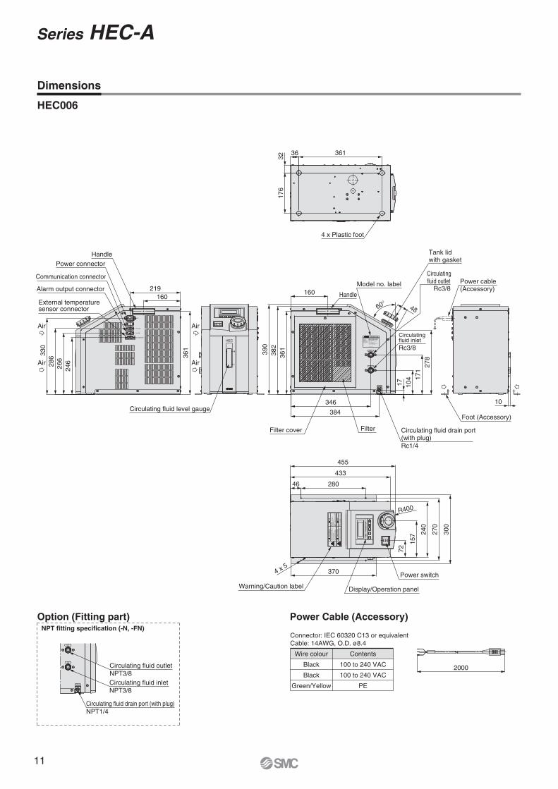
Circulating fluid inletNPT3/8
Circulating fluid outletNPT3/8
Model no. label
Handle
Filter cover
Circulating fluid outlet
Circulating fluid drain port(with plug)Rc1/4
Circulating fluid inletRc3/8
Tank lid with gasket
Filter
4 x Plastic foot
Foot (Accessory)
Power cable(Accessory)
AirAir
AirAir
Circulating fluid level gauge
Power connectorHandle
Communication connector
Alarm output connector
External temperaturesensor connector 4860°
160
382
390
346
38410
4 171
17
361
278
36 361
3217
6
10
160
361
219
246
266
28633
0
Rc3/8
R400
Power switch
Warning/Caution label Display/Operation panel
46 280
433
72
157 24
0
270
300
3704 x 5
455
Option (Fitting part)NPT fitting specification (-N, -FN)
Power Cable (Accessory)
Connector: IEC 60320 C13 or equivalentCable: 14AWG, O.D. ø8.4
Wire colour
Black
Black
Green/Yellow
Contents
100 to 240 VAC
100 to 240 VAC
PE
HEC006
Dimensions
Series HEC-A
11
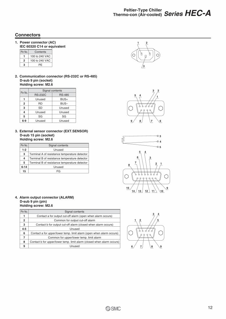
Connectors
1. Power connector (AC)IEC 60320 C14 or equivalent
4. Alarm output connector (ALARM)D-sub 9 pin (pin)Holding screw: M2.6
2. Communication connector (RS-232C or RS-485)D-sub 9 pin (socket)Holding screw: M2.6
3. External sensor connector (EXT.SENSOR)D-sub 15 pin (socket)Holding screw: M2.6
Pin No. Contents
1
2
3
100 to 240 VAC
100 to 240 VAC
PE
Pin No. Signal contents
1
2
3
4-5
6
7
8
9
Contact a for output cut-off alarm (open when alarm occurs)
Common for output cut-off alarm
Contact b for output cut-off alarm (closed when alarm occurs)
Unused
Contact a for upper/lower temp. limit alarm (open when alarm occurs)
Common for upper/lower temp. limit alarm
Contact b for upper/lower temp. limit alarm (closed when alarm occurs)
Unused
Pin No. Signal contents
1-2
3
4
5
6-14
15
Unused
Terminal A of resistance temperature detector
Terminal B of resistance temperature detector
Terminal B of resistance temperature detector
Unused
FG
Pin No.RS-232C
Signal contents
1
2
3
4
5
6-9
Unused
RD
SD
Unused
SG
Unused
RS-485
BUS+
BUS–
Unused
Unused
SG
Unused
5
4
3
1514 13 12 11 10
9
87
6
12
3
45
9876
1 2
3 4
5
9 8 7 6
5 4
3 2
1
3
21
Peltier-Type ChillerThermo-con (Air-cooled) Series HEC-A
12
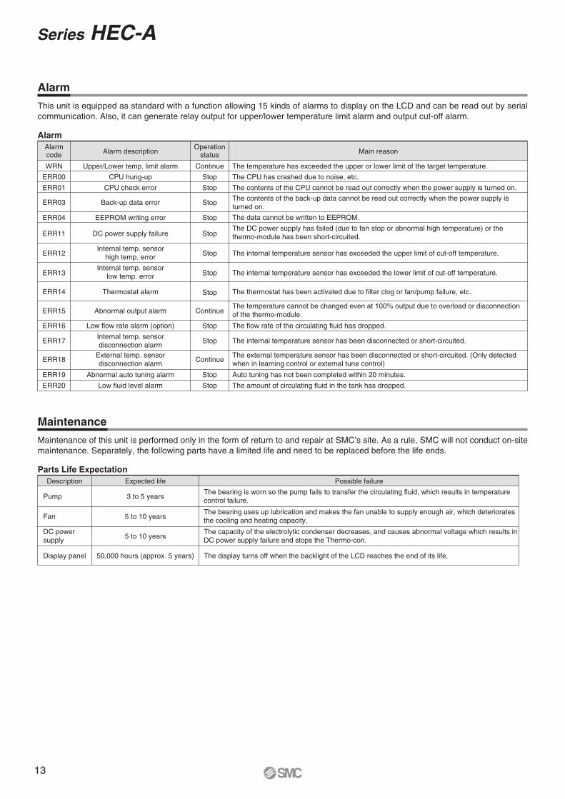
Alarm
This unit is equipped as standard with a function allowing 15 kinds of alarms to display on the LCD and can be read out by serial communication. Also, it can generate relay output for upper/lower temperature limit alarm and output cut-off alarm.
Maintenance
Maintenance of this unit is performed only in the form of return to and repair at SMC’s site. As a rule, SMC will not conduct on-site maintenance. Separately, the following parts have a limited life and need to be replaced before the life ends.
Parts Life Expectation
AlarmAlarmcode
Operationstatus Main reason
WRN
ERR00
ERR01
ERR03
ERR04
Continue
Stop
Stop
Stop
Stop
ERR11 Stop
ERR12 Stop
The temperature has exceeded the upper or lower limit of the target temperature.
The CPU has crashed due to noise, etc.
The contents of the CPU cannot be read out correctly when the power supply is turned on.
The data cannot be written to EEPROM.
The DC power supply has failed (due to fan stop or abnormal high temperature) or the thermo-module has been short-circuited.
ERR16 Stop The flow rate of the circulating fluid has dropped.
ERR17 Stop The internal temperature sensor has been disconnected or short-circuited.
ERR19
ERR20
Stop
Stop
Auto tuning has not been completed within 20 minutes.
The amount of circulating fluid in the tank has dropped.
The internal temperature sensor has exceeded the upper limit of cut-off temperature.
ERR13 Stop The internal temperature sensor has exceeded the lower limit of cut-off temperature.
ERR14 Stop The thermostat has been activated due to filter clog or fan/pump failure, etc.
ERR15 ContinueThe temperature cannot be changed even at 100% output due to overload or disconnection of the thermo-module.
ERR18
Alarm description
Upper/Lower temp. limit alarm
CPU hung-up
CPU check error
Back-up data error
EEPROM writing error
DC power supply failure
Internal temp. sensorhigh temp. error
Low flow rate alarm (option)
Internal temp. sensordisconnection alarm
Abnormal auto tuning alarm
Low fluid level alarm
Internal temp. sensorlow temp. error
Thermostat alarm
Abnormal output alarm
External temp. sensordisconnection alarm Continue
The external temperature sensor has been disconnected or short-circuited. (Only detected when in learning control or external tune control)
The contents of the back-up data cannot be read out correctly when the power supply is turned on.
Description Expected life
3 to 5 years
5 to 10 years
5 to 10 years
Pump
Fan
DC powersupply
Display panel 50,000 hours (approx. 5 years)
Possible failure
The bearing is worn so the pump fails to transfer the circulating fluid, which results in temperature control failure.
The bearing uses up lubrication and makes the fan unable to supply enough air, which deteriorates the cooling and heating capacity.
The capacity of the electrolytic condenser decreases, and causes abnormal voltage which results in DC power supply failure and stops the Thermo-con.
The display turns off when the backlight of the LCD reaches the end of its life.
Series HEC-A
13
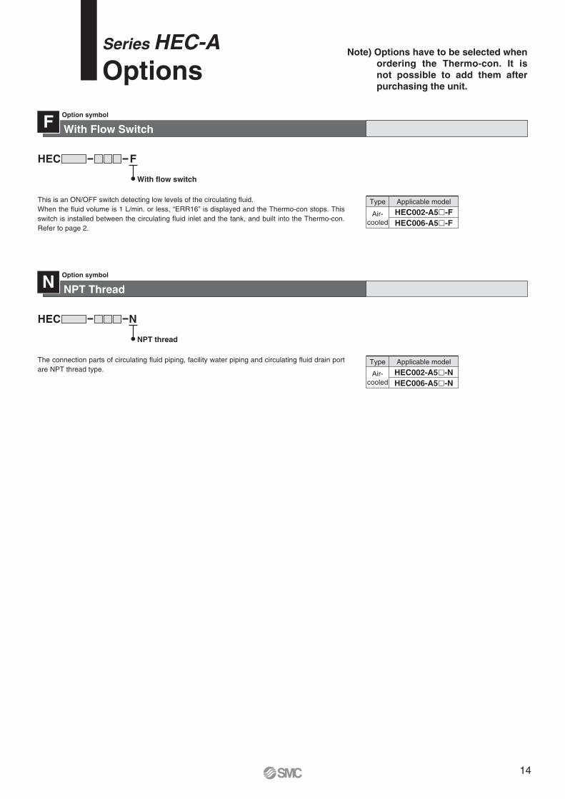
With Flow SwitchOption symbol
This is an ON/OFF switch detecting low levels of the circulating fluid. When the fluid volume is 1 L/min. or less, “ERR16” is displayed and the Thermo-con stops. This switch is installed between the circulating fluid inlet and the tank, and built into the Thermo-con. Refer to page 2.
F
FHEC
With flow switch
Air-cooled
HEC002-A5�-FHEC006-A5�-F
Type Applicable model
NPT ThreadOption symbol
The connection parts of circulating fluid piping, facility water piping and circulating fluid drain port are NPT thread type.
N
NHEC
NPT thread
Air-cooled
HEC002-A5�-NHEC006-A5�-N
Type Applicable model
Series HEC-AOptions
Note) Options have to be selected when ordering the Thermo-con. It is not possible to add them after purchasing the unit.
14

<HEC006>
The rear side is opened.
Intake
100 mmor more
100 mmor more
Discharge
The rear side is closed.
Intake
200 mmor more
200 mmor more
Discharge
The rear side is opened.
Intake
500 mmor more
500 mmor more
Discharge
The rear side is closed.
Intake
500 mmor more
500 mmor more
Discharge
Series HEC-ASpecific Product Precautions 1Be sure to read this before handling. Refer to back cover for Saftey Instructions, “Handling Precautions for SMC Products” (M-E03-3) and “Operation Manual ” for Temperature Control Equipment Precautions. The Operation Manual can be downloaded from the SMC website: http://www.smc.eu
System Design
Warning
Handling
Warning
Operating Environment/Storage Environment
Warning
Radiation Air
Caution
Note) The space must be 500 mm or more. Be sure that the ambient temperature is within the specification range.
1. This catalogue shows the specifications of the Thermo-con.1. Check detailed specifications in the separate “Product Speci-
fications”, and evaluate the compatibility of the Thermo-con with customer’s system.
2. Although the protection circuit as a single unit is installed, the customer is requested to carry out the safety design for the whole system.
1. Thoroughly read the Operation Manual. Read the Operation Manual completely before operation, and keep this manual available whenever necessary.
2. If the set temperature is repeatedly changed by 10ºC or more, the Thermo-con may fail in short periods of time.
1. Keep within the specified ambient tempera-ture and humidity range.Also, if the set temperature is too low, condensation may form on the inside of the Thermo-con or the surface of piping even within the specified ambient temperature range. Dew conden-sation can cause failure, and so must be avoided by consider-ing operating conditions.
2. The Thermo-con is not designed for clean room usage.It generates dust from the pump inside the unit and the cooling fan.
3. Low molecular siloxane can damage the con-tact of the relay.Use the Thermo-con in a place free from low molecular siloxane.
1. The inlet for radiation air must not be ex-posed to particles and dust as far as pos-sible.
2. Do not let the inlet and outlet for radiation air get closed.<HEC002>If radiation is prevented, the set temperature may not be achieved depending on the value of the set temperature and the load. Keep a space of 100 mm for opened rear side or 200 mm for closed rear side respectively.
15

Series HEC-ASpecific Product Precautions 2Be sure to read this before handling. Refer to back cover for Saftey Instructions, “Handling Precautions for SMC Products” (M-E03-3) and “Operation Manual ” for Temperature Control Equipment Precautions. The Operation Manual can be downloaded from the SMC website: http://www.smc.eu
Circulating Fluid
Circulating Fluid
Caution
CautionRadiation Air
Caution3. If more than one Thermo-con is used, consid-
er their arrangement so that the downstream sides of the Thermo-cons suck radiation air from the upstream sides. Otherwise, the performance at the downstream sides may dete-riorate. Also, the set temperature may not be achieved depend-ing on the value of the set temperature and the load. In such a case, take countermeasures such as changing the direction of the Thermo-cons to prevent the deterioration of performance.
4. If dust adheres to the filter, remove dust with a vacuum cleaner or a dry cloth.
5. Do not operate without the filter. Otherwise, dust may accumulate on the heat sink and electrical components, causing abnormal heating.
1. Use tap water or fluid which will not damage the wetted material.(Stainless steel 303, Stainless steel 304, EPDM, Polypropyl-ene, PE, PPE, Ceramics, Polyurethane)
2. Deionized water (with an electrical conductiv-ity of approx. 1 μS/cm) can be used, but may lose its electrical conductivity. Also, if a facility supplying deionized water is used, the Thermo-con may be damaged by static electricity.
3. If deionized water is used, bacteria and algae may grow in short periods of time.If the Thermo-con is operated with bacteria and algae, its cool-ing capacity or the capacity of the pump may deteriorate. Ex-change all deionized water regularly depending on the condi-tions (once a month as a guide).
4. If using a fluid other than water, please con-tact SMC beforehand.
5. The maximum operating pressure of circulat-ing fluid circuit is 0.1 MPa.If this pressure is exceeded, leakage from the tank in the Ther-mo-con can result.
6. Select a pipe with a length and diameter which al-low a flow rate of 1 L/min or more (HEC002) or 3 L/min or more (HEC006) for the circulating fluid.If the flow rate is less than these values, the Thermo-con can-not provide precise control, but also can fail because of the re-peated cooling and heating operation.
7. A magnet driven pump is used as a circulat-ing pump.A fluid which contains metal powders such as iron powder can-not be used.
8. The Thermo-con must not be operated with-out circulating fluid.The pump can break due to idling.
9. If the tank lid is opened after the supply of circu-lating fluid, the circulating fluid may spill out de-pending on the condition of external piping.
10. If an external tank is used, the circulating fluid may spill out from the internal tank lid depending on where the external tank is installed.Check that the internal tank has no leakage if using an external tank.
11. If there is a point where fluid is released to atmos-phere externally (tank or piping), minimize the piping resistance at the circulating fluid return side.If the piping resistance is too large, the piping may be crushed, or the built-in circulator tank may be deformed or cracked be-cause the pressure in the piping for return will become nega-tive. The built-in circulator tank is made of resin (PE). There-fore, the tank may be crushed if the pressure is negative. Spe-cial attention must be paid if the flow rate of the circulating fluid is high. To avoid getting negative pressure less than –0.02 MPa, the piping for return should be as thick and short as pos-sible to minimize the piping resistance. It is also effective to re-strict the flow rate of circulating fluid or remove the gasket of in-ternal tank for the release to atmosphere.
12. Fluorinated fluid is outside of the specifications. If it is used in the Thermo-con, static electricity will be gener-ated by the flow of fluid. This static electricity may be dis-charged to the board of the Thermo-con, causing damage or operation failure and loss of data of such as set temperature. Also, as the specific gravity of the fluorinated fluid is 1.5 to 1.8 times of water, the pump will be overloaded, which also causes fluorinated fluid to be outside the specifications. Therefore, if fluorinated fluid is used, please contact SMC and we will intro-duce a suitable special product (water-cooled type).
13. Avoid operation with cavitation or bubbles due to low fluid level in the tank. This may shorten the pump life.
14. If clear water is used, it should satisfy the quality standards shown below.
Standarditem
Referenceitem
Item
pH (at 25°C)
Electrical conductivity (25°C)
Chloride ion (Cl–)
Sulfuric acid ion (SO42–)
Acid consumption amount (at pH4.8)
Total hardness
Calcium hardness (CaCO3)
Ionic state silica (SiO2)
Iron (Fe)
Copper (Cu)
Sulfide ion (S2–)
Ammonium ion (NH4+)
Residual chlorine (Cl)
Free carbon (CO2)
Unit
—
[µS/cm]
[mg/L]
[mg/L]
[mg/L]
[mg/L]
[mg/L]
[mg/L]
[mg/L]
[mg/L]
[mg/L]
[mg/L]
[mg/L]
[mg/L]
Standard value
Influence
CorrosionScale
generation
6.0 to 8.0
100∗ to 300∗
50 or less
50 or less
50 or less
70 or less
50 or less
30 or less
0.3 or less
0.1 or less
Should not be detected.
0.1 or less
0.3 or less
4.0 or less
��
�����
����
������
∗ In the case of [MΩ �cm], it will be 0.003 to 0.01.� �: Factors that have an effect on corrosion or scale generation.� Even if the water quality standards are met, complete prevention of corrosion is not guaranteed.
Clear Water (as Circulating Water) Quality StandardsThe Japan Refrigeration and Air Conditioning Industry AssociationJRA GL-02-1994 “Cooling water system – Circulating type – Supply water”
16
Series HEC-ASpecific Product Precautions 3Be sure to read this before handling. Refer to back cover for Saftey Instructions, “Handling Precautions for SMC Products” (M-E03-3) and “Operation Manual ” for Temperature Control Equipment Precautions. The Operation Manual can be downloaded from the SMC website: http://www.smc.eu
1. Prevention of electric shock and fireDo not operate the switch with wet hands. Also, do not operate the Thermo-con with water left on it.
2. Action in the case of errorIf any error such as abnormal sounds, smoke, or bad smell oc-curs, cut off the power at once, and stop supplying and convey-ing fluid. Please contact SMC or a sales distributor to repair the Thermo-con.
3. Regular inspectionCheck the following items at least once a month. The inspec-tion must be done by an operator who has sufficient knowledge and experience.a) Check of displayed contents.b) Check of temperature, vibration and abnormal sounds in the
body of the Thermo-con.c) Check of the voltage and current of the power supply system.d) Check for leakage and contamination of the circulating fluid
and intrusion of foreign objects to it, and subsequent re-placement of the fluid.
e) Check for flow condition, temperature and filter of radiation air.
Maintenance
Warning
1. The set value can be written to EEPROM, but only up to approx. 1 million times. In particular, pay attention to how many of times the writing is performed using the communication function.
Communication
Caution
17

18
RoHS
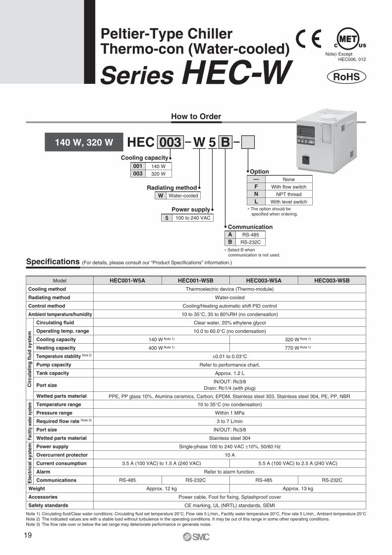
Peltier-Type ChillerThermo-con (Water-cooled)
Series HEC-WNote) Except HEC006, 012
How to Order
003 BHEC W 5140 W, 320 W
001003
140 W
320 W
Cooling capacity
Radiating methodW Water-cooled
5 100 to 240 VAC
Power supply
AB
RS-485
RS-232C
Communication
∗ Select B when communication is not used.
—FNL
None
With flow switch
NPT thread
With level switch
Option
∗ The option should be specified when ordering.
Specifications (For details, please consult our “Product Specifications” information.)
Thermoelectric device (Thermo-module)
Water-cooled
Cooling/Heating automatic shift PID control
10 to 35°C, 35 to 80%RH (no condensation)
Clear water, 20% ethylene glycol
10.0 to 60.0°C (no condensation)
±0.01 to 0.03°C
Refer to performance chart.
Approx. 1.2 L
IN/OUT: Rc3/8Drain: Rc1/4 (with plug)
10 to 35°C (no condensation)
Within 1 MPa
3 to 7 L/min
IN/OUT: Rc3/8
Stainless steel 304
Single-phase 100 to 240 VAC ±10%, 50/60 Hz
10 A
Refer to alarm function.
Power cable, Foot for fixing, Splashproof cover
CE marking, UL (NRTL) standards, SEMI
PPE, PP glass 10%, Alumina ceramics, Carbon, EPDM, Stainless steel 303, Stainless steel 304, PE, PP, NBR
RS-485 RS-232C RS-485 RS-232C
Approx. 12 kg Approx. 13 kg
140 W Note 1)
400 W Note 1)
320 W Note 1)
770 W Note 1)
3.5 A (100 VAC) to 1.5 A (240 VAC) 5.5 A (100 VAC) to 2.5 A (240 VAC)
Model HEC001-W5A HEC001-W5B HEC003-W5A HEC003-W5BCooling method
Radiating method
Control method
Ambient temperature/humidity
Circulating fluid
Operating temp. range
Cooling capacity
Heating capacity
Temperature stability Note 2)
Pump capacity
Tank capacity
Port size
Wetted parts material
Temperature range
Pressure range
Required flow rate Note 3)
Port size
Wetted parts material
Power supply
Overcurrent protector
Current consumption
Alarm
Communications
Weight
Accessories
Safety standards
Cir
cula
tin
g f
luid
sys
tem
Faci
lity
wate
r sys
tem
Ele
ctri
cal s
yste
m
Note 1) Circulating fluid/Clear water conditions: Circulating fluid set temperature 20°C, Flow rate 5 L/min., Facility water temperature 20°C, Flow rate 5 L/min., Ambient temperature 25°CNote 2) The indicated values are with a stable load without turbulence in the operating conditions. It may be out of this range in some other operating conditions.Note 3) The flow rate over or below the set range may deteriorate performance or generate noise.
19
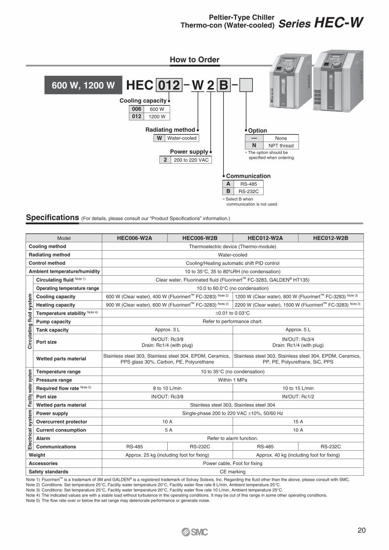
How to Order
012 BHEC W 2600 W, 1200 W
006012
600 W
1200 W
Cooling capacity
Radiating methodW Water-cooled
2 200 to 220 VAC
Power supply
AB
RS-485
RS-232C
Communication
∗ Select B when communication is not used.
—N
None
NPT thread
Option
∗ The option should be specified when ordering.
Specifications (For details, please consult our “Product Specifications” information.)
Note 1) Fluorinert™ is a trademark of 3M and GALDEN® is a registered trademark of Solvay Solexis, Inc. Regarding the fluid other than the above, please consult with SMC.Note 2) Conditions: Set temperature 25°C, Facility water temperature 20°C, Facility water flow rate 8 L/min, Ambient temperature 25°C. Note 3) Conditions: Set temperature 25°C, Facility water temperature 20°C, Facility water flow rate 10 L/min, Ambient temperature 25°C. Note 4) The indicated values are with a stable load without turbulence in the operating conditions. It may be out of this range in some other operating conditions.Note 5) The flow rate over or below the set range may deteriorate performance or generate noise.
Model HEC006-W2A HEC006-W2B HEC012-W2A HEC012-W2BCooling method
Radiating method
Control method
Ambient temperature/humidity
Circulating fluid Note 1)
Operating temperature range
Cooling capacity
Heating capacity
Temperature stability Note 4)
Pump capacity
Tank capacity
Port size
Wetted parts material
Temperature range
Pressure range
Required flow rate Note 5)
Port size
Wetted parts material
Power supply
Overcurrent protector
Current consumption
Alarm
Communications
Weight
Accessories
Safety standards
Thermoelectric device (Thermo-module)
Water-cooled
Cooling/Heating automatic shift PID control
10 to 35°C, 35 to 80%RH (no condensation)
Clear water, Fluorinated fluid (Fluorinert™ FC-3283, GALDEN® HT135)
10.0 to 60.0°C (no condensation)
±0.01 to 0.03°C
Refer to performance chart.
10 to 35°C (no condensation)
Within 1 MPa
Stainless steel 303, Stainless steel 304
Single-phase 200 to 220 VAC ±10%, 50/60 Hz
Refer to alarm function.
Power cable, Foot for fixing
CE marking
RS-485 RS-232C RS-485 RS-232C
8 to 10 L/min
IN/OUT: Rc3/8
10 A
5 A
15 A
10 A
Approx. 25 kg (including foot for fixing) Approx. 40 kg (including foot for fixing)
10 to 15 L/min
IN/OUT: Rc1/2
Approx. 3 L
IN/OUT: Rc3/8Drain: Rc1/4 (with plug)
Stainless steel 303, Stainless steel 304, EPDM, Ceramics, PPS glass 30%, Carbon, PE, Polyurethane
IN/OUT: Rc3/4Drain: Rc1/4 (with plug)
Stainless steel 303, Stainless steel 304, EPDM, Ceramics, PP, PE, Polyurethane, SiC, PPS
Approx. 5 L
600 W (Clear water), 400 W (Fluorinert™ FC-3283) Note 2)
900 W (Clear water), 600 W (Fluorinert™ FC-3283) Note 2)
1200 W (Clear water), 800 W (Fluorinert™ FC-3283) Note 3)
2200 W (Clear water), 1500 W (Fluorinert™ FC-3283) Note 3)
Cir
cula
tin
g f
luid
sys
tem
Faci
lity
wate
r sys
tem
Ele
ctri
cal s
yste
mSeries HEC-WPeltier-Type Chiller
Thermo-con (Water-cooled)
20
Facility water: 10°C
Facility water: 30°C
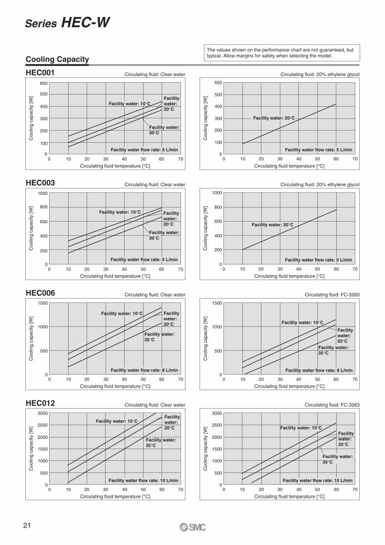
The values shown on the performance chart are not guaranteed, but typical. Allow margins for safety when selecting the model.Cooling Capacity
HEC001
Circulating fluid temperature [°C]
Coo
ling
capa
city
[W]
Circulating fluid: Clear water
0
100
200
300
400
500
600
0 10 20 30 40 50 60 70
Facility water: 20°C
Facility water flow rate: 5 L/min
Circulating fluid temperature [°C]
Coo
ling
capa
city
[W]
Circulating fluid: 20% ethylene glycol
0
100
200
300
400
500
600
0 10 20 30 40 50 60 70
Facility water flow rate: 5 L/min
Facility water: 20°C
Circulating fluid temperature [°C]
Coo
ling
capa
city
[W]
Circulating fluid: 20% ethylene glycolHEC003
Circulating fluid temperature [°C]
Coo
ling
capa
city
[W]
Circulating fluid: Clear water
0
200
400
600
800
1000
0 10 20 30 40 50 60 700
200
400
600
800
1000
0 10 20 30 40 50 60 70
Facility water flow rate: 5 L/min Facility water flow rate: 5 L/min
Facility water: 10°C
Facility water: 20°C
Facility water: 20°C
Facility water: 30°C
HEC006
Circulating fluid temperature [°C]
Coo
ling
capa
city
[W]
Circulating fluid: Clear water
0
500
1000
1500
0 10 20 30 40 50 60 70
Facility water flow rate: 8 L/min
Facility water: 10°C Facility water: 20°C
Facility water: 35°C
Circulating fluid temperature [°C]
Coo
ling
capa
city
[W]
Circulating fluid: FC-3283
0
500
1000
1500
0 10 20 30 40 50 60 70
Facility water flow rate: 8 L/min
Facility water: 10°C
Facility water: 20°C
Facility water: 35°C
Circulating fluid temperature [°C]
Coo
ling
capa
city
[W]
Circulating fluid: FC-3283
0
500
1000
1500
2000
2500
3000
0 10 20 30 40 50 60 70
HEC012
Circulating fluid temperature [°C]
Coo
ling
capa
city
[W]
Circulating fluid: Clear water
0
500
1000
1500
2000
2500
3000
0 10 20 30 40 50 60 70
Facility water flow rate: 10 L/min Facility water flow rate: 10 L/min
Facility water: 10°CFacility water: 10°C
Facility water: 20°C
Facility water: 20°C
Facility water: 35°C
Facility water: 35°C
Series HEC-W
21
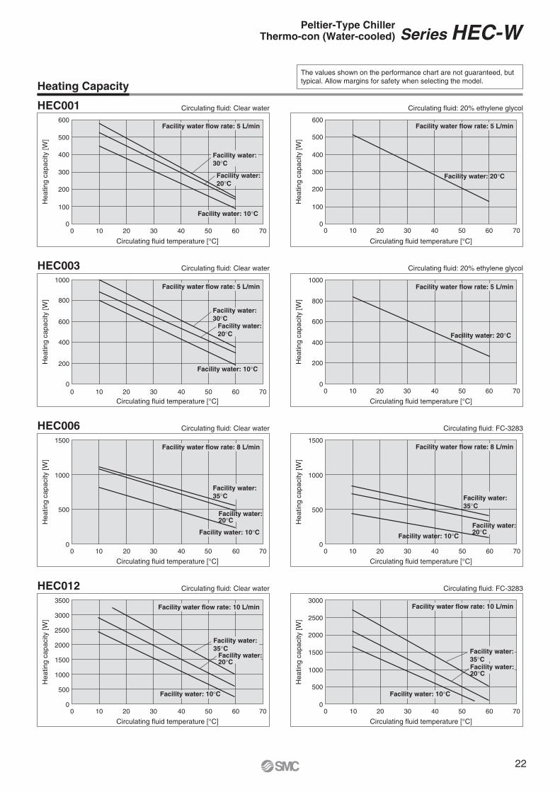
The values shown on the performance chart are not guaranteed, but typical. Allow margins for safety when selecting the model.Heating Capacity
HEC001 Circulating fluid: Clear water
Circulating fluid temperature [°C]
Hea
ting
capa
city
[W]
Circulating fluid: 20% ethylene glycol
Circulating fluid temperature [°C]
Hea
ting
capa
city
[W]
0
100
200
300
400
500
600
0 10 20 30 40 50 60 700
100
200
300
400
500
600
0 10 20 30 40 50 60 70
Facility water flow rate: 5 L/min Facility water flow rate: 5 L/min
Facility water: 30°C
Facility water: 20°C
Facility water: 10°C
Facility water: 20°C
HEC003 Circulating fluid: Clear water
Circulating fluid temperature [°C]
Hea
ting
capa
city
[W]
Circulating fluid: 20% ethylene glycol
Circulating fluid temperature [°C]
Hea
ting
capa
city
[W]
0
200
400
600
800
1000
0 10 20 30 40 50 60 700
200
400
600
800
1000
0 10 20 30 40 50 60 70
Facility water flow rate: 5 L/minFacility water flow rate: 5 L/min
Facility water: 30°C
Facility water: 20°C
Facility water: 10°C
Facility water: 20°C
HEC012 Circulating fluid: Clear water
Circulating fluid temperature [°C]
Hea
ting
capa
city
[W]
0
500
1000
1500
2000
2500
3000
3500
0 10 20 30 40 50 60 70
Circulating fluid: FC-3283
Circulating fluid temperature [°C]
Hea
ting
capa
city
[W]
0
500
1000
1500
2000
2500
3000
0 10 20 30 40 50 60 70
Circulating fluid: FC-3283
Circulating fluid temperature [°C]
Hea
ting
capa
city
[W]
0
500
1000
1500
0 10 20 30 40 50 60 70
HEC006 Circulating fluid: Clear water
Circulating fluid temperature [°C]
Hea
ting
capa
city
[W]
0
500
1000
1500
0 10 20 30 40 50 60 70
Facility water flow rate: 10 L/minFacility water flow rate: 10 L/min
Facility water flow rate: 8 L/min Facility water flow rate: 8 L/min
Facility water: 35°C
Facility water: 20°C
Facility water: 10°C
Facility water: 35°C
Facility water: 20°C
Facility water: 10°C
Facility water: 35°C
Facility water: 20°C
Facility water: 10°C
Facility water: 35°CFacility water: 20°C
Facility water: 10°C
Series HEC-WPeltier-Type ChillerThermo-con (Water-cooled)
22
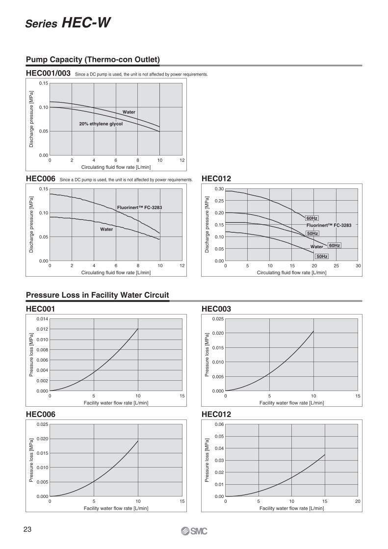
Pump Capacity (Thermo-con Outlet)
HEC001/003 Since a DC pump is used, the unit is not affected by power requirements.
Circulating fluid flow rate [L/min]
Dis
char
ge p
ress
ure
[MP
a]
0 2 4 6 8 10 120.00
0.05
0.10
0.15
Water
20% ethylene glycol
HEC012
Circulating fluid flow rate [L/min]
Dis
char
ge p
ress
ure
[MP
a]
0.00
0.05
0.10
0.15
0.20
0.25
0.30
0 5 10 15 20 25 30
HEC006 Since a DC pump is used, the unit is not affected by power requirements.
Circulating fluid flow rate [L/min]
Dis
char
ge p
ress
ure
[MP
a]
0.00
0.05
0.10
0.15
0 2 4 6 8 10 12
Fluorinert™ FC-3283
Water
60Hz
Fluorinert™ FC-3283
50Hz
50Hz
60HzWater
Pressure Loss in Facility Water Circuit
HEC012
Facility water flow rate [L/min]
Pre
ssur
e lo
ss [M
Pa]
0.06
0.05
0.04
0.03
0.02
0.01
0.000 5 10 15 20
HEC003
Facility water flow rate [L/min]
Pre
ssur
e lo
ss [M
Pa]
0 5 10 150.000
0.005
0.010
0.015
0.020
0.025
HEC001
Facility water flow rate [L/min]
Pre
ssur
e lo
ss [M
Pa]
0 5 10 150.000
0.002
0.004
0.006
0.008
0.010
0.012
0.014
HEC006
Facility water flow rate [L/min]
Pre
ssur
e lo
ss [M
Pa]
0.000
0.005
0.010
0.015
0.020
0.025
0 5 10 15
Series HEC-W
23
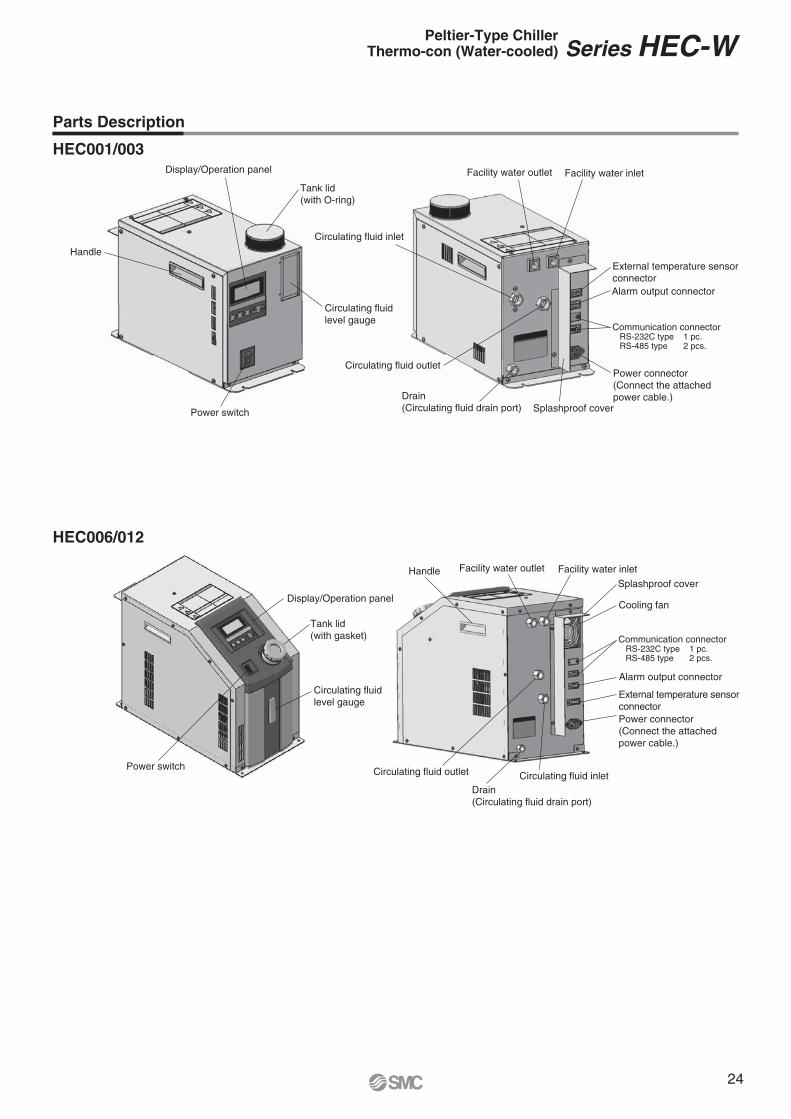
HEC006/012
HEC001/003Display/Operation panel
Tank lid (with O-ring)
Circulating fluid level gauge
Power switch
Handle
Circulating fluid inlet
Facility water outlet Facility water inlet
External temperature sensorconnectorAlarm output connector
Communication connector RS-232C type 1 pc. RS-485 type 2 pcs.
Power connector(Connect the attached power cable.)
Splashproof coverDrain(Circulating fluid drain port)
Circulating fluid outlet
Display/Operation panel
Tank lid (with gasket)
Circulating fluid level gauge
Power switch
Handle Facility water outlet Facility water inlet
Splashproof cover
Cooling fan
Communication connector RS-232C type 1 pc. RS-485 type 2 pcs.
Alarm output connector
External temperature sensorconnectorPower connector(Connect the attached power cable.)
Circulating fluid inletDrain(Circulating fluid drain port)
Circulating fluid outlet
Parts Description
Series HEC-WPeltier-Type ChillerThermo-con (Water-cooled)
24

Dimensions
HEC001-W5�HEC003-W5�
182
(32)
120
(45.
5)
(55)
10 348
Warning/Caution label
4 x
wid
th 5
Tank lid (with O-ring)
Foot (Accessory)
245
(190)
ø72
(25)
184
Display/Operation panel
Power switch
Circulating fluid level gauge
197
214 27
100
41321
(13)
30 30368
Handle
Splashproof cover(Accessory)
DRAIN
AC
RS-232C
ALARM
EXT.SENSOR
INOUT
RECIRCULATING WATER
INRADIATING WATER
OUT221
160143
28
0 148
84 104
642819
0
150128
82
37
0
Circulatingfluid inletRc3/8
Facility water outletRc3/8
Facility water inletRc3/8
Circulating fluid outletRc3/8
External temperaturesensor connector
Alarm output connector
Communicationconnector
Power connectorModel no. label
Drain(Circulating fluid drain port)
For NPT thread specification (-N), all fittings (including those at the circulating fluid drain port) are made of NPT.
2000
Power cable (Accessory)
Power Cable (Accessory)
Connector: IEC 60320 C13 or equivalentCable: 14AWG, O.D. ø8.4
Wire colour
Black
Black
Green/Yellow
Contents
100 to 240 VAC
100 to 240 VAC
PE
Series HEC-W
25
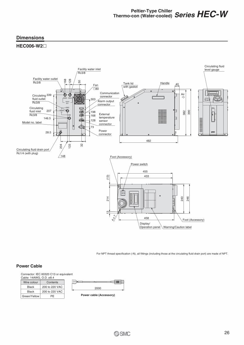
For NPT thread specification (-N), all fittings (including those at the circulating fluid drain port) are made of NPT.
Dimensions
HEC006-W2�
458
13(1
3)
455
433
214
246
240
Foot (Accessory)
Power switch
Foot (Accessory)
Warning/Caution labelDisplay/Operation panel
4 x
7
HEC
H
L
40
390
382
482
Circulating fluid level gauge
Tank lid with gasket
Handle
Air
RS-232C
ALARM
EXT.SENSOR
AC
RECIRCULATING FLUID
IN
OUT
OUT
RADIATING WATER
IN
DRAIN
303
50
339
207
146.5
28.5
198168
128
73
204
148
133 32
168
128Facility water outlet
Rc3/8
Circulating fluid outletRc3/8
Circulating fluid inletRc3/8
Model no. label
Circulating fluid drain portRc1/4 (with plug)
Facility water inletRc3/8
Fan�80
Communicationconnector
Alarm output connector
External temperaturesensorconnector
Power connector
2000
Power cable (Accessory)
Power Cable
Connector: IEC 60320 C13 or equivalentCable: 14AWG, O.D. ø8.4
Wire colour
Black
Black
Green/Yellow
Contents
200 to 220 VAC
200 to 220 VAC
PE
Series HEC-WPeltier-Type ChillerThermo-con (Water-cooled)
26
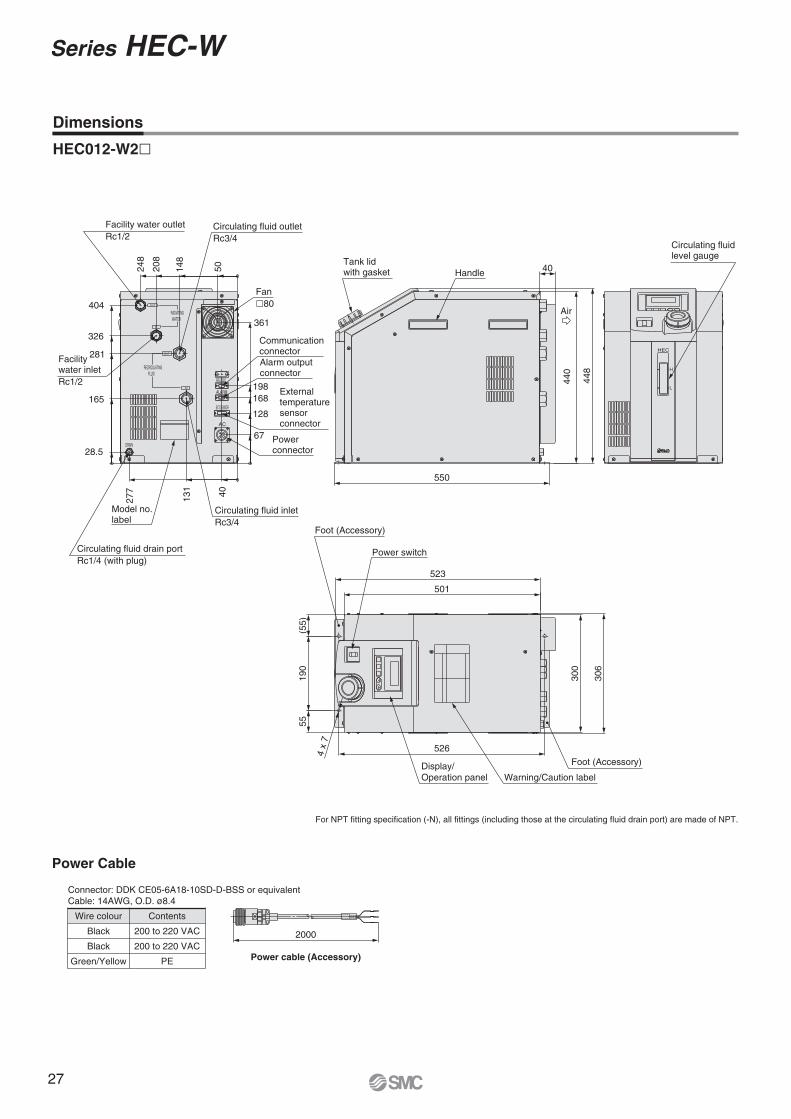
Dimensions
HEC012-W2�
523
501
(55)
190
55
526
306
300
Foot (Accessory)
Power switch
4 x
7
Display/Operation panel Warning/Caution label
Foot (Accessory)
HEC
H
L
40
448
440
550
Circulating fluid level gauge
Tank lid with gasket Handle
Air
IN
OUT
IN
RS-232C
ALARM
EXT.SENSOR
AC
DRAIN
RECIRCULATING FLUID
OUT
RADIATING WATER 361
5040
198168
128
404
326
281
165
28.5
248
208
148
277
131
67
Facility water inletRc1/2
Facility water outletRc1/2
Circulating fluid outletRc3/4
Fan�80
CommunicationconnectorAlarm output connector
External temperaturesensorconnector
Circulating fluid inletRc3/4
Power connector
Model no.label
Circulating fluid drain portRc1/4 (with plug)
For NPT fitting specification (-N), all fittings (including those at the circulating fluid drain port) are made of NPT.
2000
Power cable (Accessory)
Connector: DDK CE05-6A18-10SD-D-BSS or equivalentCable: 14AWG, O.D. ø8.4
Wire colour
Black
Black
Green/Yellow
Contents
200 to 220 VAC
200 to 220 VAC
PE
Power Cable
Series HEC-W
27
1514 13 12 11 10
9
87
6
12
3
45
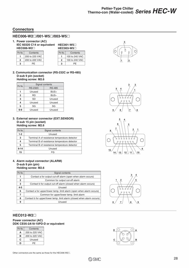
Pin No. Signal contents
1-2
3
4
5
6-14
15
Unused
Terminal A of resistance temperature detector
Terminal B of resistance temperature detector
Terminal B of resistance temperature detector
Unused
FG
3. External sensor connector (EXT.SENSOR)D-sub 15 pin (socket)Holding screw: M2.6
HEC006-W2�/001-W5�/003-W5�
Connectors
Pin No. Contents
1
2
3
1. Power connector (AC)IEC 60320 C14 or equivalentHEC006-W2�
Pin No. Contents
1
2
3
HEC001-W5�HEC003-W5�
200 to 220 VAC
200 to 220 VAC
PE
100 to 240 VAC
100 to 240 VAC
PE21
3
Pin No.RS-232C
Signal contents
1
2
3
4
5
6-9
Unused
RD
SD
Unused
SG
Unused
RS-485
BUS+
BUS–
Unused
Unused
SG
Unused
2. Communication connector (RS-232C or RS-485)D-sub 9 pin (socket)Holding screw: M2.6
9 8 7 6
5 4
3 2
1
4. Alarm output connector (ALARM)D-sub 9 pin (pin)Holding screw: M2.6
Pin No. Signal contents
1
2
3
4-5
6
7
8
9
Contact a for output cut-off alarm (open when alarm occurs)
Common for output cut-off alarm
Contact b for output cut-off alarm (closed when alarm occurs)
Unused
Contact a for upper/lower temp. limit alarm (open when alarm occurs)
Common for upper/lower temp. limit alarm
Contact b for upper/lower temp. limit alarm (closed when alarm occurs)
Unused 9876
1 2
3 4
5
Pin No. Contents
A
B
C
D
200 to 220 VAC
200 to 220 VAC
Unused
PE
Power connector (AC)DDK CE05-2A18-10PD-D or equivalent
HEC012-W2�
Other connectors are the same as those for the HEC006-W2�.
B
A
C
D
Series HEC-WPeltier-Type ChillerThermo-con (Water-cooled)
28
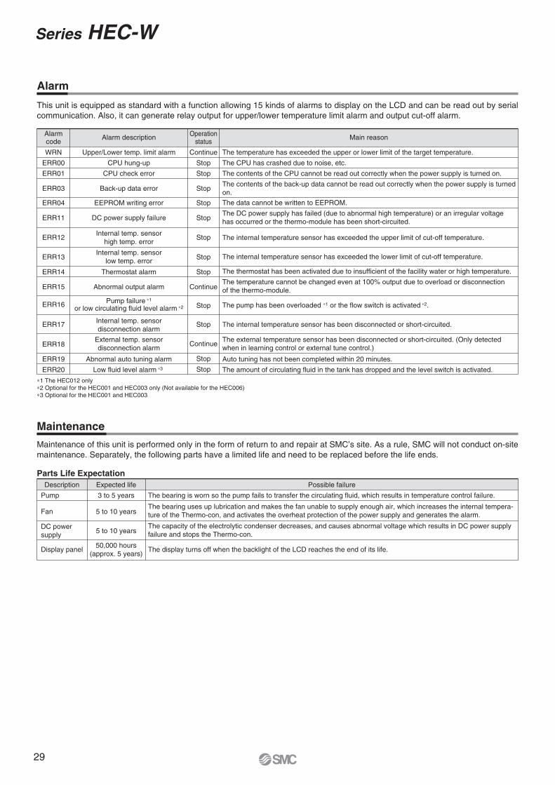
Alarm
Maintenance
Maintenance of this unit is performed only in the form of return to and repair at SMC’s site. As a rule, SMC will not conduct on-site maintenance. Separately, the following parts have a limited life and need to be replaced before the life ends.
Parts Life ExpectationDescription Expected life
3 to 5 years
5 to 10 years
5 to 10 years
Pump
Fan
DC powersupply
Display panel50,000 hours
(approx. 5 years)
Possible failure
The bearing is worn so the pump fails to transfer the circulating fluid, which results in temperature control failure.
The bearing uses up lubrication and makes the fan unable to supply enough air, which increases the internal tempera-ture of the Thermo-con, and activates the overheat protection of the power supply and generates the alarm.
The capacity of the electrolytic condenser decreases, and causes abnormal voltage which results in DC power supply failure and stops the Thermo-con.
The display turns off when the backlight of the LCD reaches the end of its life.
This unit is equipped as standard with a function allowing 15 kinds of alarms to display on the LCD and can be read out by serial communication. Also, it can generate relay output for upper/lower temperature limit alarm and output cut-off alarm.
Alarmcode
Alarm description Operationstatus
Main reason
WRN
ERR00
ERR01
ERR03
ERR04
ERR11
ERR12
ERR13
ERR14
ERR15
ERR16
ERR17
ERR18
ERR19
ERR20
Upper/Lower temp. limit alarm
CPU hung-up
CPU check error
Back-up data error
EEPROM writing error
DC power supply failure
Internal temp. sensorhigh temp. error
Internal temp. sensorlow temp. error
Thermostat alarm
Abnormal output alarm
Pump failure ∗1
or low circulating fluid level alarm ∗2
Internal temp. sensordisconnection alarm
External temp. sensordisconnection alarm
Abnormal auto tuning alarm
Low fluid level alarm ∗3
Continue
Stop
Stop
Stop
Stop
Stop
Stop
Stop
Stop
Continue
Stop
Continue
Stop
Stop
Stop
The temperature has exceeded the upper or lower limit of the target temperature.
The CPU has crashed due to noise, etc.
The contents of the CPU cannot be read out correctly when the power supply is turned on.
The data cannot be written to EEPROM.
The DC power supply has failed (due to abnormal high temperature) or an irregular voltage has occurred or the thermo-module has been short-circuited.
The internal temperature sensor has exceeded the upper limit of cut-off temperature.
The thermostat has been activated due to insufficient of the facility water or high temperature.
The temperature cannot be changed even at 100% output due to overload or disconnection of the thermo-module.
The pump has been overloaded ∗1 or the flow switch is activated ∗2.
The external temperature sensor has been disconnected or short-circuited. (Only detected when in learning control or external tune control.)
Auto tuning has not been completed within 20 minutes.
The amount of circulating fluid in the tank has dropped and the level switch is activated.
The internal temperature sensor has been disconnected or short-circuited.
The internal temperature sensor has exceeded the lower limit of cut-off temperature.
The contents of the back-up data cannot be read out correctly when the power supply is turned on.
∗1 The HEC012 only∗2 Optional for the HEC001 and HEC003 only (Not available for the HEC006)∗3 Optional for the HEC001 and HEC003
Series HEC-W
29
F
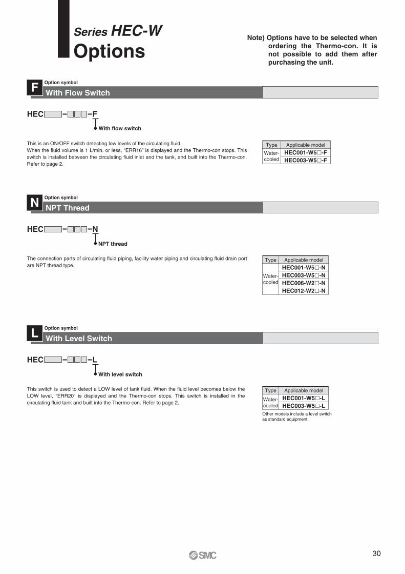
This is an ON/OFF switch detecting low levels of the circulating fluid. When the fluid volume is 1 L/min. or less, “ERR16” is displayed and the Thermo-con stops. This switch is installed between the circulating fluid inlet and the tank, and built into the Thermo-con. Refer to page 2.
HEC001-W5�-FHEC003-W5�-F
Water-cooled
Type Applicable model
NPT ThreadOption symbol
The connection parts of circulating fluid piping, facility water piping and circulating fluid drain port are NPT thread type.
N
NHEC
NPT thread
Water-cooled
HEC001-W5�-NHEC003-W5�-NHEC006-W2�-NHEC012-W2�-N
Type Applicable model
With Level SwitchOption symbol
This switch is used to detect a LOW level of tank fluid. When the fluid level becomes below the LOW level, “ERR20” is displayed and the Thermo-con stops. This switch is installed in the circulating fluid tank and built into the Thermo-con. Refer to page 2.
L
LHEC
With level switch
Water-cooled
HEC001-W5�-LHEC003-W5�-L
Type Applicable model
Other models include a level switch as standard equipment.
Note) Options have to be selected when ordering the Thermo-con. It is not possible to add them after purchasing the unit.
Series HEC-WOptions
With Flow SwitchOption symbol
FHEC
With flow switch
30
100 mmor more
Leave space100 mm ormore
Discharge
Intake
Intake
100 mmor more
Intake
Leave space150 mm ormore
Series HEC-WSpecific Product Precautions 1Be sure to read this before handling. Refer to back cover for Saftey Instructions, “Handling Precautions for SMC Products” (M-E03-3) and “Operation Manual ” for Temperature Control Equipment Precautions. The Operation Manual can be downloaded from the SMC website: http://www.smc.eu
1. This catalogue shows the specifications of the Thermo-con.1. Check detailed specifications in the separate “Product Speci-
fications”, and evaluate the compatibility of the Thermo-con with customer’s system.
2. Although the protection circuit as a single unit is installed, the customer is requested to carry out the safety design for the whole system.
System Design
WarningOperating Environment/Storage Environment
Warning
Circulating Fluid
Caution1. Use tap water or fluid which will not damage
the wetted parts material as described in this catalogue’s specifications.(PPE, PP glass 10%, Alumina ceramics, Carbon, EPDM, Stain-less steel 303, Stainless steel 304, PE, PP, NBR)
2. Deionised water (with an electrical conductiv-ity of approx. 1 μS/cm) can be used, but may lose its electrical conductivity.
<HEC006/012>
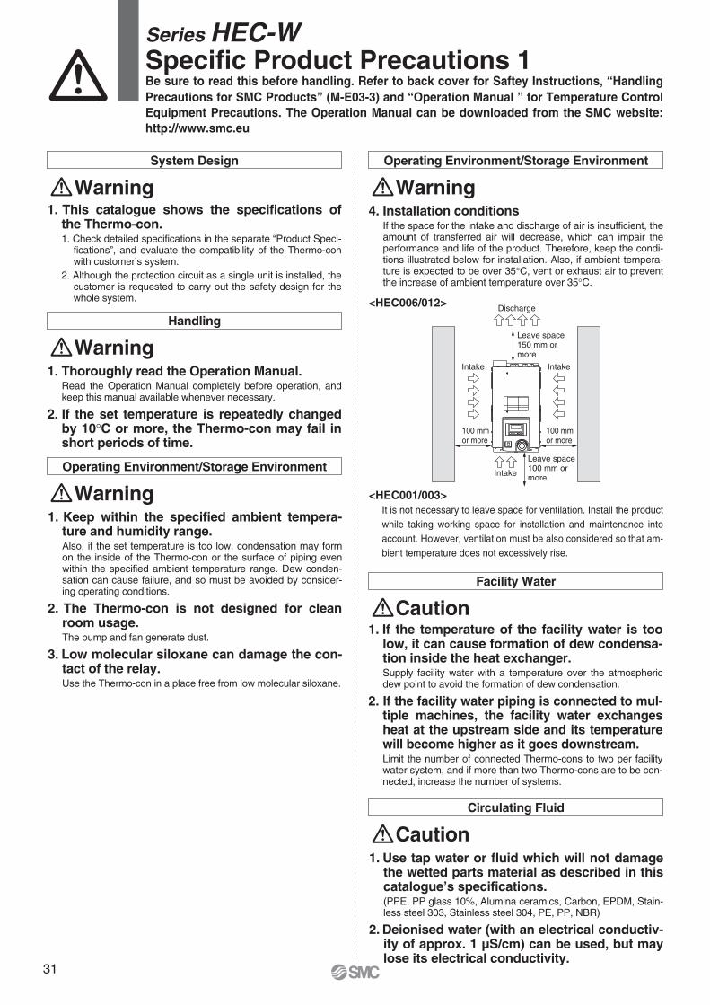
<HEC001/003>It is not necessary to leave space for ventilation. Install the product while taking working space for installation and maintenance into account. However, ventilation must be also considered so that am-bient temperature does not excessively rise.
Facility Water
Caution
Operating Environment/Storage Environment
Warning
Handling
Warning1. Thoroughly read the Operation Manual.
Read the Operation Manual completely before operation, and keep this manual available whenever necessary.
2. If the set temperature is repeatedly changed by 10°C or more, the Thermo-con may fail in short periods of time.
1. Keep within the specified ambient tempera-ture and humidity range.Also, if the set temperature is too low, condensation may form on the inside of the Thermo-con or the surface of piping even within the specified ambient temperature range. Dew conden-sation can cause failure, and so must be avoided by consider-ing operating conditions.
2. The Thermo-con is not designed for clean room usage.The pump and fan generate dust.
3. Low molecular siloxane can damage the con-tact of the relay.Use the Thermo-con in a place free from low molecular siloxane.
4. Installation conditionsIf the space for the intake and discharge of air is insufficient, the amount of transferred air will decrease, which can impair the performance and life of the product. Therefore, keep the condi-tions illustrated below for installation. Also, if ambient tempera-ture is expected to be over 35°C, vent or exhaust air to prevent the increase of ambient temperature over 35°C.
1. If the temperature of the facility water is too low, it can cause formation of dew condensa-tion inside the heat exchanger. Supply facility water with a temperature over the atmospheric dew point to avoid the formation of dew condensation.
2. If the facility water piping is connected to mul-tiple machines, the facility water exchanges heat at the upstream side and its temperature will become higher as it goes downstream.Limit the number of connected Thermo-cons to two per facility water system, and if more than two Thermo-cons are to be con-nected, increase the number of systems.
31

Series HEC-WSpecific Product Precautions 2Be sure to read this before handling. Refer to back cover for Saftey Instructions, “Handling Precautions for SMC Products” (M-E03-3) and “Operation Manual ” for Temperature Control Equipment Precautions. The Operation Manual can be downloaded from the SMC website: http://www.smc.eu
Communication
Caution
Maintenance
Warning
Circulating Fluid
Caution14. If clear water is used, it should satisfy the
quality standards shown below.
Circulating Fluid
Caution
Clear Water (as Circulating Water) Quality Standards
Standarditem
Referenceitem
Item
pH (at 25°C)
Electrical conductivity (25°C)
Chloride ion (Cl–)
Sulfuric acid ion (SO42–)
Acid consumption amount (at pH4.8)
Total hardness
Calcium hardness (CaCO3)
Ionic state silica (SiO2)
Iron (Fe)
Copper (Cu)
Sulfide ion (S2–)
Ammonium ion (NH4+)
Residual chlorine (Cl)
Free carbon (CO2)
Unit
—
[µS/cm]
[mg/L]
[mg/L]
[mg/L]
[mg/L]
[mg/L]
[mg/L]
[mg/L]
[mg/L]
[mg/L]
[mg/L]
[mg/L]
[mg/L]
Standard value
Influence
CorrosionScale
generation
6.0 to 8.0
100∗ to 300∗
50 or less
50 or less
50 or less
70 or less
50 or less
30 or less
0.3 or less
0.1 or less
Should not be detected.
0.1 or less
0.3 or less
4.0 or less
��
�����
����
������
3. If deionized water is used, bacteria and algae may grow in a short period.If the Thermo-con is operated with bacteria and algae, its heat exchanging capacity or the capacity of the pump may deterio-rate. Exchange all deionized water regularly depending on the conditions (once a month as a guide).
4. If using a fluid other than this catalogue, please contact SMC beforehand.
5. The maximum operating pressure of circulat-ing fluid circuit is 0.1 MPa.If this pressure is exceeded, leakage from the tank in the Ther-mo-con can result.
6. Select a pipe with a length and diameter which allow a flow rate of 3 L/min or more for the circulating fluid. If the flow rate is less than 3 L/min, the Thermo-con cannot pro-vide precise control, but also can fail because of the repeated cooling and heating operation.
7. A magnet driven pump is used as a circulat-ing pump.A fluid which contains metal powders such as iron powder can-not be used.
8. The Thermo-con must not be operated with-out circulating fluid.The pump can break due to idling.
9. If the tank lid is opened after the supply of circulat-ing fluid, the circulating fluid may spill out depend-ing on the condition of external piping.
10. If an external tank is used, the circulating fluid may spill out from the internal tank lid depending on where the external tank is installed.Check that the internal tank has no leakage if using an external tank.
11. If there is a point where fluid is released to atmo-sphere externally (tank or piping), minimize the pip-ing resistance at the circulating fluid return side.If the piping resistance is too large, the piping may be crushed, or the built-in circulator tank may be deformed or cracked because the pressure in the piping for return will become negative. The built-in circulator tank is made of resin (PE). Therefore, the tank may be crushed if the pressure is negative. Special attention must be paid if the flow rate of the circulating fluid is high. To avoid getting negative pressure less than –0.02 MPa, the piping for return should be as thick and short as possible to minimize the piping resistance. It is also effective to restrict the flow rate of circulating fluid or remove the gasket of internal tank for the release to atmosphere.
12. If fluorinated fluid is used in the Thermo-con (HEC006/012), static electricity will be gener-ated by the flow of fluid. This static electricity may be discharged to the board of the Ther-mo-con, causing damage or operation failure and loss of data of such as set temperature.Ground pipe in order to remove static electricity.
13. Avoid operation with cavitation or bubbles due to low fluid level in the tank. This may shorten the pump life.
The Japan Refrigeration and Air Conditioning Industry AssociationJRA GL-02-1994 “Cooling water system – Circulating type – Supply water”
1. The set value can be written to EEPROM, but only up to approx. 1 million times. In particular, pay attention to how many of times the writing is performed using the communication function.
1. Prevention of electric shock and fireDo not operate the switch with wet hands. Also, do not operate the Thermo-con with water left on it.
2. Action in the case of errorIf any error such as abnormal sounds, smoke, or bad smell oc-curs, cut off the power at once, and stop supplying and convey-ing fluid. Please contact SMC or a sales distributor to repair the Thermo-con.
3. Regular inspectionCheck the following items at least once a month. The inspec-tion must be done by an operator who has sufficient knowledge and experience.a) Check of displayed contents.b) Check of temperature, vibration and abnormal sounds in the
body of the Thermo-con.c) Check of the voltage and current of the power supply system.d) Check for leakage and contamination of the circulating fluid
and intrusion of foreign objects to it, and subsequent re-placement of water.
e) Check for leakage, quality change, flow rate and temperature of facility water.
∗ In the case of [MΩ �cm], it will be 0.003 to 0.01.� �: Factors that have an effect on corrosion or scale generation.� Even if the water quality standards are met, complete prevention of corrosion
is not guaranteed.
32
Lithuania +370 5 2308118 www.smclt.lt [email protected] +31 (0)205318888 www.smcpneumatics.nl [email protected] +47 67129020 www.smc-norge.no [email protected] +48 (0)222119616 www.smc.pl [email protected] +351 226166570 www.smc.eu [email protected] +40 213205111 www.smcromania.ro [email protected] +7 8127185445 www.smc-pneumatik.ru [email protected] +421 (0)413213212 www.smc.sk [email protected] +386 (0)73885412 www.smc.si [email protected] +34 902184100 www.smc.eu [email protected] +46 (0)86031200 www.smc.nu [email protected] +41 (0)523963131 www.smc.ch [email protected] +90 212 489 0 440 www.smcpnomatik.com.tr [email protected] UK +44 (0)845 121 5122 www.smcpneumatics.co.uk [email protected]
Specifications are subject to change without prior notice and any obligation on the part of the manufacturer.SMC CORPORATION Akihabara UDX 15F, 4-14-1, Sotokanda, Chiyoda-ku, Tokyo 101-0021, JAPAN Phone: 03-5207-8249 FAX: 03-5298-5362
1st printing TO printing TO 00 Printed in Spain
Austria +43 (0)2262622800 www.smc.at [email protected] +32 (0)33551464 www.smcpneumatics.be [email protected] +359 (0)2807670 www.smc.bg [email protected] Croatia +385 (0)13707288 www.smc.hr [email protected] Republic +420 541424611 www.smc.cz [email protected] Denmark +45 70252900 www.smcdk.com [email protected] Estonia +372 6510370 www.smcpneumatics.ee [email protected] +358 207513513 www.smc.fi [email protected] +33 (0)164761000 www.smc-france.fr [email protected] +49 (0)61034020 www.smc.de [email protected] +30 210 2717265 www.smchellas.gr [email protected] +36 23511390 www.smc.hu [email protected] +353 (0)14039000 www.smcpneumatics.ie [email protected] +39 0292711 www.smcitalia.it [email protected] +371 67817700 www.smclv.lv [email protected]
Safety Instructions Be sure to read “Handling Precautions for SMC Products” (M-E03-3) before using.
SMC Corporation (Europe)
1. The compatibility of the product is the responsibility of the person who designs the equipment or decides its specifications.
Since the product specified here is used under various operating conditions, its compatibility with specific equipment must be decided by the person who designs the equipment or decides its specifications based on necessary analysis and test results. The expected performance and safety assurance of the equipment will be the responsibility of the person who has determined its compatibility with the product. This person should also continuously review all specifications of the product referring to its latest catalogue information, with a view to giving due consideration to any possibility of equipment failure when configuring the equipment.
2. Only personnel with appropriate training should operate machinery and equipment.
The product specified here may become unsafe if handled incorrectly. The assembly, operation and maintenance of machines or equipment including our products must be performed by an operator who is appropriately trained and experienced.
3. . Do not service or attempt to remove product and machinery/equipment until safety is confirmed.1. The inspection and maintenance of machinery/equipment should only be performed
after measures to prevent falling or runaway of the driven objects have been confirmed.
2. When the product is to be removed, confirm that the safety measures as mentioned above are implemented and the power from any appropriate source is cut, and read and understand the specific product precautions of all relevant products carefully.
3. Before machinery/equipment is restarted, take measures to prevent unexpected operation and malfunction.
4. Contact SMC beforehand and take special consideration of safety measures if the product is to be used in any of the following conditions. 1. Conditions and environments outside of the given specifications, or use outdoors or in
a place exposed to direct sunlight.2. Installation on equipment in conjunction with atomic energy, railways, air navigation,
space, shipping, vehicles, military, medical treatment, combustion and recreation, or equipment in contact with food and beverages, emergency stop circuits, clutch and brake circuits in press applications, safety equipment or other applications unsuitable for the standard specifications described in the product catalogue.
3. An application which could have negative effects on people, property, or animals requiring special safety analysis.
4. Use in an interlock circuit, which requires the provision of double interlock for possible failure by using a mechanical protective function, and periodical checks to confirm proper operation.
Warning Limited warranty and Disclaimer/Compliance Requirements The product used is subject to the following “Limited warranty and Disclaimer” and “Compliance Requirements”.Read and accept them before using the product.
1. The product is provided for use in manufacturing industries.The product herein described is basically provided for peaceful use in manufacturing industries. If considering using the product in other industries, consult SMC beforehand and exchange specifications or a contract if necessary. If anything is unclear, contact your nearest sales branch.
CautionSMC products are not intended for use as instruments for legal metrology.Measurement instruments that SMC manufactures or sells have not been qualified by type approval tests relevant to the metrology (measurement) laws of each country.Therefore, SMC products cannot be used for business or certification ordained by the metrology (measurement) laws of each country.
Caution
Limited warranty and Disclaimer1. The warranty period of the product is 1 year in service or 1.5 years
after the product is delivered, wichever is first.∗2)
Also, the product may have specified durability, running distance or replacement parts. Please consult your nearest sales branch.
2. For any failure or damage reported within the warranty period which is clearly our responsibility, a replacement product or necessary parts will be provided. This limited warranty applies only to our product independently, and not to any other damage incurred due to the failure of the product.
3. Prior to using SMC products, please read and understand the warranty terms and disclaimers noted in the specified catalogue for the particular products.
∗2) Vacuum pads are excluded from this 1 year warranty.A vacuum pad is a consumable part, so it is warranted for a year after it is delivered. Also, even within the warranty period, the wear of a product due to the use of the vacuum pad or failure due to the deterioration of rubber material are not covered by the limited warranty.
Compliance Requirements1. The use of SMC products with production equipment for the manufacture of
weapons of mass destruction (WMD) or any other weapon is strictly prohibited.
2. The exports of SMC products or technology from one country to another are governed by the relevant security laws and regulations of the countries involved in the transaction. Prior to the shipment of a SMC product to another country, assure that all local rules governing that export are known and followed.
These safety instructions are intended to prevent hazardous situations and/or equipment damage. These instructions indicate the level of potential hazard with the labels of “Caution,” “Warning” or “Danger.” They are all important notes for safety and must be followed in addition to International Standards (ISO/IEC)∗1), and other safety regulations.
∗1) ISO 4414: Pneumatic fluid power – General rules relating to systems. ISO 4413: Hydraulic fluid power – General rules relating to systems. IEC 60204-1: Safety of machinery – Electrical equipment of machines. (Part 1: General requirements) ISO 10218-1: Manipulating industrial robots - Safety. etc.
Caution indicates a hazard with a low level of risk which, if not avoided, could result in minor or moderate injury.
Warning indicates a hazard with a medium level of risk which, if not avoided, could result in death or serious injury.
Caution:
Warning:
Danger : Danger indicates a hazard with a high level of risk which, if not avoided, will result in death or serious injury.
Safety Instructions