peh-7,8,10mya(-k) - mitsubishi-les.info · electrical data 9 capacity tables 10 ... use only...
TRANSCRIPT

AIR-COOLED SPLIT-TYPE DUCTED AIR CONDITIONERS
DATA BOOK
Series
HEAT PUMP
COOLING ONLY
PEH-7,8,10
PE-7,8,10

HOW TO USE THIS DATA BOOK
without permission.Warning Don't change this databook
On detail you can see the online Guide of Acrobat reader.
SPECIFICATION SUBJECT TO CHANGE WITHOUT NOTICE.
Tools and buttonsThe toolbar contains tools for selecting and viewing documents. Select a tool by clicking the tool icon. To hide or show the toolbar, choose Hide Toolbar or Show Toolbar from the Window menu.
The toolbar contains the following tools and buttons:
Click the Page Only button to close the overview area of the window.
Click the Bookmarks and Page button to open the overview area and display bookmarks created for the document. Click a bookmark’s name to go to the location marked by that bookmark.
Click the Thumbnails and Page button to open the overview area and display thumbnail images of each document page. Click a thumbnail to go to the page marked by that thumbnail.
Use the hand tool to move a document page on-screen when it does not fit within the window. Drag the hand tool in the direction you want to move the page.
Use the zoom tools to magnify and reduce the page display by a factor of 2.
Use the select text tool to select text in a document, which can then be copied to the Clipboard by using the Copy command. Choose Select Graphics from the Tools menu to select graphics in a document.
Use the Previous Page or Next Page button to move the document backward or forward, one page at a time.
Use the First Page or Last Page button to move the document to the first or last page of a document.
Use the Go Back and Go Forward buttons to retrace your steps in a document, moving to each view in the order visited. Go Back also returns you to the original document after you click a link to another document.
Using notesWhen you encounter a note in a PDF document, double-click it to open the note window. To find the next note in the document, choose Find Next Note from the Tools menu.To close the note window, click the close box in the upper left corner of the note.

-1-
CONTENTS
PAGE NUMBER
SAFETY FOR USE 2
A COMPLETE LINE UP 4
FEATURES 5
DESCRIPTIONS 5
MECHANICAL SPECIFICATIONS 6
TYPICAL INSTALLATION EXAMPLE 6
SPECIFICATION 7
ELECTRICAL DATA 9
CAPACITY TABLES 10
SOUND DATA 16
FAN PERFORMANCE CURVE
OUTLINE DIMENSIONS
WIRING DIAGRAMS
ELECTRICAL OPERATION FLOW CHART
REFRIGERATION SCHEMATICS
SAFETY & CONTROL DEVICES
SPECIAL ORDER
PHYSICAL DATA
INSTALLATION
INSTRUCTIONS FOR USE
SPECIFICATION GUIDELINES
17
18
20
36
37
38
38
39
45
56
60

-2-
SAFETY FOR USE Before conducting installation work, please read this “SAFETY FOR USE” carefully
for correct installation. Since the caution items shown here contain important description relative to safety, please observe them without fail.
After reading, please keep it with you together the Instruction Manual, and read it again at the movement of the unit.
The unit should not be installed by the user.If the unit is installed improperly, explosion, waterleakage, electric shock or fire may be result.Consult your dealer or specialist subcontractor forrepair and movement.
For installation, conduct the work correctly byfollowing the Installation Manual.Improper installation may cause a fire, electrical shockor water leakage.
Install the unit on a spot sufficiently durable againstthe unit weight.Insufficient durability can cause an injury by the fallingdown of unit.
All electric work must be performed by licensedtechnician, according to local regulations and theinstructions given in this manual.The units should be powered by dedicated power lines.Power lines with insufficient capacity or improperelectrical work may result in electric shock or fire.
Use only the specified cables for wiring. Theconnections must be made secured withouttension the terminals.Improper connection or fastening can cause a fire orelectrical shock.
The unit should be installed according to theinstructions in order to minimize the risk of damagefrom earthquakes, typhoons or strong winds.Improper installation work can cause an injury by thefalling down of the unit.
The outdoor unit must be installed on stable, flatsurface, in a place where there is no accumulationof snow , leaves or rubbish.The outdoor unit should be installed in a locationwhere air and noise emitted by the unit will notdisturb the neighbors. The indoor unit should besecurely installed.If the unit is loosely mounted, it may fall, and cause injury.
Never repair the unit, remodel or transfer it toanother site by yourself.If they are performed improperly, water leakage, electricshock or fire may result. If you need to have the unitrepaired or moved, consult your dealer.
Use only the specified refrigerant (R-22) to chargethe refrigerant circuit.Do not mix it with any other refrigerant and do not allowair to remain in the circuit. Air enclosed in the circuit can cause high pressure resulting in a rupture and other hazards.
Ventilate the room if refrigerant leaks duringInstallation.The refrigerant heated generates poisonous gas bydecomposition which can cause poisoning.
After completing installation work, make sure thatrefrigerant gas has not leaked.If refrigerant gas has leaked and exposed to fan heater,stove, oven and so on, it may generate noxious gases.
Take a proper measure to suppress the criticalconcentration of refrigerant if leaked wheninstalling the unit in a small room.The limit density is made not to be exceeded even if therefrigerant leaks by any chance.You are necessary to ventilation measures to preventthe accident. If the refrigerant leaks, hypoxia accidentmay caused.For the countermeasure to be taken, consult yourdealer.
The terminal block cover of unit must be firmlyattached to prevent entry of dust and moisture.Improper mounting of the cover cause electric shock orfire.
Use only optional parts authorised by MitsubishiElectric.If the accessories are installed improperly, waterleakage, electric shock or fire may result.
Ask your dealer or an authorised company to installthem.
Erroneous handling gives a high possibility to induce serious results such as death or heavy injury.
Erroneous handling may induce serious injury depending on the situation.
Warning
Warning
Caution

-3-
Refrain from installing the unit in an area whereflammable gas can accumulate around the unit.If the flammable gas can accumulate around the unit, anexplosion can occur.When the unit is installed at telecommunicationcenters or hospitals, take a proper provisionagainst noise.The erroneous operation of air conditioner may beinduced by inverter equipment, independent powerdevice, medical equipment or communicationequipment.While the erroneous operation of medical equipment orcommunication equipment may caused by the airconditioner.For special use as for foods, animals/plants,precision equipment or art objects, the applicabilityshould be confirmed beforehand.As the use for the applications other than thatdesigned originally may result in the deterioration of thequality. Consult your dealer in this regard.Do not use the unit under a special atmosphere.Installing the unit at the following places may cause atrouble, a place where much machine oil, salt sonnet,humidity or dust, spa district, a place full of sulfur gas,volatile gas, or corrosive gas, a place near highfrequency processing machine.Thermal insulation of the drain pipes is necessaryprevent dew condensation.If the drain pipes are not properly insulated,condensation will result and drip on ceiling, floor or otherpossessions.The drain piping must process by surely,and insulatethe drain piping not to be dewy.When the room humidity exceeds 80% or when thedrain pipe is clogged, water may drip from the indoorunit. The outdoor unit produces condensation during theheating operation.Make sure to provide drainage around the outdoor unit ifsuch condensation is likely to cause damage.Install drain piping according to this InstallationManual to ensure proper drainage.Place thermal insulation on the pipes to preventcondensation.Improper drain piping may cause water leakage anddamage to furniture or other possessions.The unit must be properly earth connected.Do not connect the earth wire to gas pipe, city waterpipe, lightning rod or telephone earth wire.Improper earth connection may cause electrical shock.When installing at a watery place, provide anelectric leak breaker.Failure to mount the electric leak breaker may causeelectrical shock.
Make sure that there is a main power switch. Use breaker or fuse with proper capacity.
Using a wire or a copper wire instead of proper capacityof fuse can cause fire or trouble.Other appliances connected to the same line could causean overload.For the power lines, use standard cables ofsufficient current capacity.Otherwise, current leakage, overheating or fire mayoccur.When installing the power lines, do not applytension to the cables.The tighten or loosen the connections may cause generateheat and cause fire.
Arrange the configuration of wiring not to bring upthe panel and terminal cover, and fasten the paneland terminal cover securely.The poor mounting of the panel or terminal cover maycause the heat generation of the terminal connection,a fire or electrical shock.Do not wash the unit with water.If washed with water, electrical shock may be caused.
Do not handle the switch with wet hands.Otherwise electrical shock can be resulted.
Be very careful on handling the unit. When carrying in outdoor unit, be sure to support it atfour points.Carrying in and lifting with 3-point support may makeoutdoor unit unstable, resulting in a fall of it.The unit should not be carried by only one person if it ismore than 20kg.Some units use PP bands for packing.Do not use any PP band for delivery purpose.Do not touch the heat exchanger fins with your bearhands.Doing so may cut your hands.Be sure to safely dispose the packaging materials.Packaging materials, such as catches and other metalor wooden parts, may cause stabs or other injuries.Tear off and discard plastic packing bags so thatchildren will not play any of them.If children play with a plastic bag which was not torn off, it may cause a risk of suffocation.
The base and attachments of the unit should beperiodically checked for looseness, cracks or otherdamage.If such defects are left uncorrected, the unit may fall andcause personal injury or property damage.
Turn on the main power switch more than 6 hoursbefore starting operation.Do not turn the main power switch OFF during seasonsof heavy use, doing so can result In failure.Do not touch the compressor or refrigerant pipingwithout wearing glove on your hands.Touching directly such part can cause a burn orfrostbite as it becomes high or low temperatureaccording to the refrigerant state.Do not touch the metal edges inside the unitwithout wearing glove on your hands.Touching directly it may injure your hands.Do not remove the front panel or the fan guard fromthe outdoor unit when it is running.You could be injured if you touch rotating, hot or high-voltage parts.
Do not operate the air conditioner without the airfilter set place.Dust may accumulate, and cause a failure.At emergency (if you smell something burning), stopoperation and turn the power source switch off.Continuing the operation without eliminating theemergency state may cause a machine trouble, fire, orelectrical shock.After stopping operation, be sure to wait for fiveminutes before turning off the main power switch.Otherwise, water leakage or unit failure may occur.
Caution

-4-
PE(H)-7 PE(H)-8 PE(H)-10
kcal/h 15,400 18,900 24,800
Cooling capacity BTU/h 61,000 75,100 98,300
kW 17.9 22.0 28.8
kcal/h 15,600 18,900 24,800
Heating capacity(PEH only)
BTU/h 61,800 75,100 98,300
kW 18.1 22.0 28.8Note: Cooling & heating capacities are based following conditions. Cooling: Indoor:27 DB, 19 WB; Outdoor: 35 DB Heating: Indoor:21 DB; Outdoor: 7 DB, 6 DB (PEH only) Cooling and Heating capacities are based 5m pipe length
Indoor unit
Outdoor unit
A COMPLETE LINE UP

-5-
High sensible cooling capacity.The sensible cooling capacity has been significantlyimproved through balanced optimised heat exchanger design.
Comfort heating. (PEH only)
Highly efficient operation.The EER(Energy Efficiency Ratio) on these modelsis greatly improved by revised design specificationsand by being manufactured stringently to MitsubishiElectric high quality standards.
Labour saving installation.The unit operation can commence immediately afterconnection to the power supply, refrigerant piping,drain piping, ducting and control system.
Mitsubishi Electric air conditioners series PE(H)/PU(H)are available in a wide range of sizes and models toenables the designer to select the best model foreach application.Series PE(H)/PU(H)-7,8,10 units are completelyassembled, wired and strictly tested at the factory.
Low ambient cooling.In applications with relatively high internal loads,there may be a requirement for the PE(H) series tooperate on cooling at low ambient conditions.Special order parts is available to maintain the refrigerationcircuit in balance at outdoor temperatures as low as -5 .Please consult your local Mitsubishi Electric Salesoffice for application advice on these parts.
Wide electrical control capability.The PE(H)-K series may be ordered in either or oftwo control configurations.The factory standard is for provision of 24 voltterminal block to enable a field wired control of thecontractors choice to be connected.Alternatively, for models PE(H)-7,8,10 the intelligent"K" series remote control system may be ordered.The K control utilises a microprocessor and includesliquid crystal display with touch pad for adjustmentof control parameters.These special parts give the flexibility to enableconnection to building management system, smokespill cycles, economy cycles, remote monitoring etc.Please consult your local Mitsubishi Electric Salesoffice for application advice on these control.
With the development of PE(H)/PU(H) series demandsfor such features as light weight, compactness,increased capacity, appropriate static pressure, airflow control, and having flexibility of inter facingenergy saving electronic controls, MitsubishiElectric have met market expectations.
FEATURES
DESCRIPTIONS
The PEH series are designed to provide effectiveheating even when the outside temperature is down to -10 .

-6-
General All units are factory assembled, piped, internally wired. They are also tested and checked under a strict quality control system in the factory. Exterior surfaces of all units of outdoor unit are phosphatized, zinc-coated steel with powder coating and ivory white baked enamel finish.
Refrigeration Controls Refrigeration controls include condenser fan, evaporator fan and compressor contactors.
Compressors All units have high efficiency type hermetic line starting compressors. Compressors are equipped with thermal overload protector, over-current relay and high pressure protection control. Crankcase heaters are standard.
Evaporator Coils Highly efficient cross-finned coil are applied to provide a larger cooling capacity with low air speed on the coil. Coils are made of 9.52mm OD and 0.35mm thick seamless copper tubing mechanically bonded to 0.12mm thick aluminium fins and are factory leak tested at a pressure of 3.3MPa. They are provided with strainers attached to the capillary tubes to further ensure a clean system.
Condenser Coils Unnecessary power input due to higher discharge pressure is avoided by high performance designs of cross-finned coil. Condenser coils are made of 9.52mm OD, 0.35mm thick seamless copper tubes mechanically bonded to0. 12mm thick aluminium fins and factory pressure and leak tested at 3.3MPa.
Evaporator Fans The sirocco direct-drive fans are made of galvanised steel and balanced to proved accurate air flow performance at low noise level.
Condenser Fan The direct-drive propeller fan is dynamically balanced, to ensure smooth airflow. A weatherproof three-phase squirrel cage induction motor is used to drive the condenser fan.
MECHANICAL SPECIFICATIONS
TYPICAL INSTALLATION EXAMPLE
PU(H)
PE(H)
PE(H)PU(H)

NOTICE 1. COOLING CAPACITY IS BASED FOLLOWING CONDITIONS. INDOOR:27 DB, 19 WB ;OUTDOOR :35 DB CAPACITY IS BASED 5M PIPE LENGTH.
2. CAPACITIES ARE GROSS CAPACITIES WHICH DO NOT INCLUDE A DEDUCTION FOR EVAPORATOR FAN MOTOR HEAT.
3. SPECIFICATION SUBJECT TO CHANGE WITHOUT NOTICE.
SPECIFICATIONS
-7-
PE-7,8,10MYC(-K) COOLING ONLY
POWER SUPPLY 1PH 2W220/240V 50Hz3PH 4W380/415V 50Hz
3PH 4W380/415V 50Hz3PH 4W380/415V 50Hz
3PH 4W380/415V 50Hz3PH 4W380/415V 50Hz
CAPACITY STEPS
INDOOR UNITEXTERNAL FINISH
EXTERNAL FINISH
DIMENSION
NET WEIGHT
NET WEIGHT
INDOOR COILFANFAN MOTOR
FAN MOTOR OUTPUT
MOTOR OUTPUT
AIR FLOW
EXTERNAL STATICPRESSUREDRAIN CONNECTIONOUTDOOR UNIT
COLOR
OUTDOOR COILFANFAN MOTOR
PROTECTION DEVICES
ITEM PE-7MYC(-K)PU-7MYC
PE-8MYC(-K)PU-8MYC
PE-10MYC(-K)PU-10MYC
INDOOR
OUTDOOR
TOTAL COOLING CAPACITY(GROSS)
SENSIBLE COOLING CAPACITY(GROSS)
kWBTU/Hkcal/h
kWBTU/Hkcal/h
%REFRIGERANTREFRIGERANT CONTROL
PE-7MYC(-K) PE-8MYC(-K) PE-10MYC(-K)
17.9 22.0 28.861,100 75,100 98,300
15,400 18,900 24,800
14.3 17.6 23.048,800 60,100 78,500
12,300 15,100 19,8000-100R-22
CAPILLARY TUBE
HEIGHTWIDTHDEPTH
mmmmmm
DIMENSION HEIGHTWIDTHDEPTH
mm
mm
mm
mm
CMMCFML/S
AIR FLOW CMMCFML/S
mmAq
Pa
COMPRESSORkW
kW
MOTOR OUTPUT kW
kg
kg
HIGH PRESSURE SWITCH, FREEZE PROTECTION, FUSE
INTERNAL THERMOSTAT (COMP & INDOOR FAN, OUTDOOR FAN)OVER CURRENT RELAY (COMP & INDOOR FAN, OUTDOOR FAN)
GALVANIZED STEEL428
1,415 1,615650
67 70 84CROSS FIN
CENTRIFUGAL (GALVANIZED STEEL) -DIRECT DRIVE
SINGLE PHASE MOTOR THREE PHASE CAGE INDUCTION MOTOR
0.21 0.7 1.0
12.5
12525.4
602,119
1,000
702,4721,167
903,179
1,500
PU-7MYC PU-8MYC PU-10MYCACRYLIC RESIN COATING
MUNSELL 5Y 8/1980
1,400700
202 205 230
HERMETIC LINE START (RECIPROCATING)5.5 7.5
CROSS FINPROPELLER -DIRECT DRIVE
THREE PHASE CAGE INDUCTION MOTOR
0.09X2 0.15X2
190 220
6,711 7,770
3,167
0.15X2
2107,4153,000 3,667

-8-
NOTICE 1. COOLING & HEATING CAPACITIES ARE BASED FOLLOWING CONDITIONS. COOLING : INDOOR :27 DB;19 WB;OUTDOOR :35 DB HEATING : INDOOR :21 DB; OUTDOOR :7 DB,6 WB COOLING AND HEATING CAPACITIES ARE BASED 5M PIPE LENGTH.
2. CAPACITIES ARE GROSS CAPACITIES WHICH DO NOT INCLUDE A DEDUCTION FOR EVAPORATORFAN MOTOR HEAT.
3. SPECIFICATION SUBJECT TO CHANGE WITHOUT NOTICE.
PEH-7,8,10MYA(-K)HEAT PUMP
POWER SUPPLY 1PH 2W220/240V 50Hz3PH 4W380/415V 50Hz
3PH 4W380/415V 50Hz3PH 4W380/415V 50Hz
3PH 4W380/415V 50Hz3PH 4W380/415V 50Hz
CAPACITY STEPS
INDOOR UNITEXTERNAL FINISH
EXTERNAL FINISH
DIMENSION
NET WEIGHT
NET WEIGHT
INDOOR COILFANFAN MOTOR
FAN MOTOR OUTPUT
MOTOR OUTPUT
AIR FLOW
EXTERNAL STATICPRESSUREDRAIN CONNECTIONOUTDOOR UNIT
COLOR
OUTDOOR COILFANFAN MOTOR
PROTECTION DEVICES
ITEM PEH-7MYA(-K)PUH-7MYC
PEH-8MYA(-K)PUH-8MYC
PEH-10MYA(-K)PUH-10MYC
INDOOR
OUTDOOR
TOTAL COOLING CAPACITY(GROSS)
TOTAL HEATING CAPACITY(GROSS)
SENSIBLE COOLING CAPACITY(GROSS)
kWBTU/Hkcal/h
kWBTU/Hkcal/h
kWBTU/Hkcal/h
%REFRIGERANTREFRIGERANT CONTROL
PEH-7MYA(-K) PEH-8MYA(-K) PEH-10MYA(-K)
17.9 22.0 28.861,100 75,100 98,300
15,400 18,900 24,800
14.3 17.6 23.048,800 60,100 78,500
12,300 15,100 19,80018.8 22.0 28.8
64,100 75,100 98,300
16,200 18,900 24,8000-100R-22
CAPILLARY TUBE
HEIGHTWIDTHDEPTH
mmmmmm
DIMENSION HEIGHTWIDTHDEPTH
mm
mm
mm
mm
CMMCFML/S
AIR FLOW CMMCFML/S
mmAq
Pa
COMPRESSORkW
kW
MOTOR OUTPUT kW
kg
kg
HIGH PRESSURE SWITCH, FREEZE & FROST PROTECTION, FUSE
INTERNAL THERMOSTAT (COMP & INDOOR FAN, OUTDOOR FAN)OVER CURRENT RELAY (COMP & INDOOR FAN, OUTDOOR FAN)
GALVANIZED STEEL428
1,415 1,615650
67 70 84CROSS FIN
CENTRIFUGAL (GALVANIZED STEEL) -DIRECT DRIVE
SINGLE PHASE MOTOR THREE PHASE CAGE INDUCTION MOTOR
0.21 0.7 1.0
12.5
12525.4
602,119
1,000
702,4721,167
903,179
1,500
PUH-7MYC PUH-8MYC PUH-10MYCACRYLIC RESIN COATING
MUNSELL 5Y 8/1980
1,400700
211 214 240
HERMETIC LINE START (RECIPROCATING)5.5 7.5
CROSS FINPROPELLER -DIRECT DRIVE
THREE PHASE CAGE INDUCTION MOTOR
0.09X2 0.15X2
167 190
5,898 6,711
2,783
0.09X2
1675,8982,783 3,167

-9-
COOLING
PEH-8MYA(-K) PEH-10MYA(-K)PE-8MYC(-K)
PEH-7MYA(-K)PE-7MYC(-K) PE-10MYC(-K)
OUTDOOR FAN INPUT RUN CURRENT 3.2 1.2 2.0
RUN CURRENT 10.7 12.3 15.9
RUN CURRENT 0.7 0.7 1.0 0.4 0.4 0.5
INDOOR FAN INPUT 0.8 0.6 1.0
COMPRESSOR INPUT 6.0 6.8 8.6 START CURRENT 74 83 82 POWER FACTORTOTAL RUN CURRENT A
A%
kW
kWA
kWA
AkW
- 74% 74% 14.6 14.2 18.9
TOTAL INPUT 7.2 7.8 10.1
OUTDOOR FAN INPUT RUN CURRENT 3.5 1.3 2.1
RUN CURRENT 11.6 13.4 17.6
RUN CURRENT 0.8 0.8 1.0 0.4 0.4 0.5
INDOOR FAN INPUT 0.8 0.6 1.0
COMPRESSOR INPUT 6.0 6.8 8.6 START CURRENT 81 91 90 POWER FACTORTOTAL RUN CURRENT A
A%
kW
kWA
kWA
AkW
- 74% 74% 15.9 15.5 20.7
TOTAL INPUT 7.2 7.8 10.1
HEATING (PEH only)
VOLT ITEM PEH-7MYA(-K) PEH-8MYA(-K) PEH-10MYA(-K)TOTAL INPUT kW 6.3 6.5 8.3TOTAL RUN CURRENT A 13.6 12.4 16.0
PEH-7 POWER FACTOR % - 72% 73%240V START CURRENT A 74 83 82
COMPRESSOR INPUT kW 5.1 5.5 6.8PEH- RUN CURRENT A 9.7 10.5 13.0 8,10 INDOOR FAN INPUT kW 0.8 0.6 1.0415V RUN CURRENT A 3.2 1.2 2.0
OUTDOOR FAN INPUT kW 0.4 0.4 0.5 RUN CURRENT A 0.7 0.7 1.0TOTAL INPUT kW 6.3 6.5 8.3TOTAL RUN CURRENT A 14.9 13.6 17.5
PEH-7 POWER FACTOR % - 72% 73%220V START CURRENT A 81 91 90
COMPRESSOR INPUT kW 5.1 5.5 6.8PEH- RUN CURRENT A 10.6 11.5 14.4 8,10 INDOOR FAN INPUT kW 0.8 0.6 1.0380V RUN CURRENT A 3.5 1.3 2.1
OUTDOOR FAN INPUT kW 0.4 0.4 0.5 RUN CURRENT A 0.8 0.8 1.0
ELECTRICAL DATA
ITEMVOLT
PE(H)-7 240V
PE(H)- 8,10 415V
PE(H)-7 220V
PE(H)- 8,10 380V

OUTDOOR DB INDOOR INDOOR 20.0 25.0 30.0 35.0 40.0 46.0
DB WB Q
kW
SHC
kW
SHF T/I
kW
Q
kW
SHC
kW
SHF T/I
kW
Q
kW
SHC
kW
SHF T/I
kW
Q
kW
SHC
kW
SHF T/I
kW
Q
kW
SHC
kW
SHF T/I
kW
Q
kW
SHC
kW
SHF T/I
kW
15 16.9 11.7 0.72 5.4 16.5 11.5 0.72 5.7 15.8 11.1 0.73 6.1 15.1 10.8 0.74 6.6 14.3 10.4 0.76 7.1 13.6 10.1 0.77 7.820 16 17.7 10.8 0.63 5.5 17.2 10.5 0.64 5.8 16.5 10.2 0.64 6.2 15.8 9.9 0.65 6.7 15.0 9.5 0.66 7.2 14.2 9.1 0.67 7.9
17 18.4 9.6 0.55 5.6 17.9 9.4 0.55 5.9 17.2 9.1 0.56 6.3 16.5 8.8 0.56 6.8 15.7 8.5 0.57 7.4 14.8 8.0 0.57 8.0
15 16.9 13.5 0.83 5.4 16.5 13.3 0.83 5.7 15.8 13.0 0.85 6.1 15.1 12.7 0.87 6.6 14.3 12.4 0.90 7.1 13.6 12.1 0.92 7.816 17.7 12.8 0.75 5.5 17.2 12.5 0.75 5.8 16.5 12.2 0.77 6.2 15.8 11.9 0.78 6.7 15.0 11.6 0.80 7.2 14.2 11.2 0.82 7.9
22 17 18.4 11.8 0.67 5.6 17.9 11.6 0.67 5.9 17.2 11.3 0.68 6.3 16.5 11.0 0.69 6.8 15.7 10.7 0.71 7.4 14.8 10.3 0.72 8.018 19.3 10.9 0.59 5.7 18.7 10.6 0.59 6.0 18.0 10.4 0.60 6.5 17.2 10.0 0.61 6.9 16.5 9.8 0.62 7.5 15.5 9.4 0.63 8.119 19.9 9.7 0.51 5.8 19.3 9.4 0.51 6.2 18.7 9.2 0.52 6.6 17.9 8.9 0.52 7.1 17.0 8.6 0.53 7.6 16.0 8.2 0.54 8.2
16 17.7 15.0 0.87 5.5 17.2 14.7 0.88 5.8 16.5 14.5 0.90 6.2 15.8 14.1 0.92 6.7 15.0 13.8 0.95 7.2 14.2 13.4 0.97 7.917 18.4 14.0 0.78 5.6 17.9 13.7 0.79 5.9 17.2 13.4 0.81 6.3 16.5 13.1 0.82 6.8 15.7 12.8 0.84 7.4 14.8 12.4 0.87 8.018 19.3 12.9 0.69 5.7 18.7 12.7 0.70 6.0 18.0 12.4 0.71 6.5 17.2 12.0 0.72 6.9 16.5 11.8 0.74 7.5 15.5 11.4 0.76 8.1
24 19 19.9 11.8 0.61 5.8 19.3 11.6 0.62 6.2 18.7 11.4 0.63 6.6 17.9 11.1 0.64 7.1 17.0 10.7 0.66 7.6 16.0 10.3 0.67 8.220 21.2 10.9 0.54 6.0 20.4 10.6 0.54 6.3 19.7 10.4 0.55 6.7 18.8 10.1 0.56 7.2 17.9 9.8 0.57 7.8 16.9 9.4 0.58 8.421 22.0 9.7 0.46 6.1 21.2 9.4 0.46 6.4 20.5 9.2 0.47 6.8 19.6 9.0 0.48 7.3 18.7 8.7 0.49 7.9 17.6 8.2 0.49 8.5
18 19.3 15.0 0.80 5.7 18.7 14.7 0.81 6.0 18.0 14.5 0.83 6.5 17.2 14.0 0.84 6.9 16.5 13.9 0.87 7.5 15.5 13.4 0.89 8.119 19.9 13.9 0.72 5.8 19.3 13.6 0.73 6.2 18.7 13.4 0.74 6.6 17.9 13.1 0.76 7.1 17.0 12.8 0.78 7.6 16.0 12.3 0.80 8.2
26 20 21.2 13.1 0.64 6.0 20.4 12.7 0.64 6.3 19.7 12.5 0.66 6.7 18.8 12.2 0.67 7.2 17.9 11.9 0.69 7.8 16.9 11.4 0.70 8.421 22.0 12.1 0.57 6.1 21.2 11.7 0.57 6.4 20.5 11.5 0.58 6.8 19.6 11.3 0.60 7.3 18.7 10.9 0.61 7.9 17.6 10.4 0.62 8.522 22.8 11.0 0.50 6.2 22.1 10.7 0.50 6.5 21.3 10.5 0.51 6.9 20.4 10.2 0.52 7.4 19.5 9.8 0.53 8.0 18.4 9.4 0.53 8.623 23.7 9.9 0.43 6.3 23.0 9.5 0.43 6.7 22.1 9.3 0.44 7.1 21.2 9.0 0.45 7.6 20.3 8.6 0.45 8.1 19.2 8.1 0.45 8.8
19 19.9 15.9 0.82 5.8 19.3 15.8 0.84 6.2 18.7 15.7 0.86 6.6 17.9 15.4 0.88 7.1 17.0 15.0 0.91 7.6 16.0 14.5 0.93 8.220 21.2 15.3 0.74 6.0 20.4 15.0 0.76 6.3 19.7 14.8 0.77 6.7 18.8 14.5 0.79 7.2 17.9 14.1 0.81 7.8 16.9 13.6 0.83 8.421 22.0 14.1 0.66 6.1 21.2 13.8 0.67 6.4 20.5 13.6 0.69 6.8 19.6 13.3 0.70 7.3 18.7 13.0 0.72 7.9 17.6 12.4 0.73 8.5
28 22 22.8 13.1 0.59 6.2 22.1 12.9 0.60 6.5 21.3 12.6 0.61 6.9 20.4 12.4 0.63 7.4 19.5 12.1 0.64 8.0 18.4 11.7 0.66 8.623 23.7 12.0 0.53 6.3 23.0 11.8 0.53 6.7 22.1 11.5 0.54 7.1 21.2 11.3 0.55 7.6 20.3 11.1 0.57 8.1 19.2 10.7 0.58 8.824 24.7 10.9 0.46 6.5 24.0 10.6 0.46 6.8 23.1 10.4 0.47 7.2 22.2 10.1 0.48 7.7 21.2 10.0 0.49 8.2 20.0 9.7 0.51 8.9
20 21.2 17.2 0.83 6.0 20.4 16.7 0.84 6.3 19.7 16.5 0.86 6.7 18.8 16.1 0.88 7.2 17.9 16.0 0.92 7.8 16.9 15.7 0.95 8.421 22.0 16.2 0.76 6.1 21.2 15.8 0.77 6.4 20.5 15.6 0.78 6.8 19.6 15.3 0.80 7.3 18.7 15.1 0.83 7.9 17.6 14.6 0.86 8.5
30 22 22.8 15.1 0.68 6.2 22.1 14.8 0.69 6.5 21.3 14.6 0.71 6.9 20.4 14.3 0.72 7.4 19.5 14.0 0.74 8.0 18.4 13.6 0.76 8.623 23.7 14.2 0.62 6.3 23.0 14.1 0.63 6.7 22.1 13.7 0.64 7.1 21.2 13.4 0.65 7.6 20.3 13.2 0.67 8.1 19.2 12.8 0.69 8.824 24.7 13.2 0.55 6.5 24.0 13.0 0.56 6.8 23.1 12.8 0.57 7.2 22.2 12.5 0.58 7.7 21.2 12.2 0.60 8.2 20.0 11.8 0.61 8.9
* Q: COOLING CAPACITY SHC: SENSIBLE HEAT CAPACITY T/I: TOTAL INPUT
Factor for Various Air FlowAIR CMM 50 60 70
VOLUME L/S 830 1,000 1,167CAPACITY 0.975 1.0 1.024
COOLING TOTAL INPUT 0.989 1.0 1.009SHC 0.964 1.0 1.040
Cooling Capacity (Air Flow)PE-7MYC(-K), PEH-7MYA(-K)
CAPACITY TABLES
PEH-7MYA(-K)PE-7MYC(-K)
-10-

OUTDOOR DB INDOOR INDOOR -5.0 0.0 5.0 10.0 15.0
kW
SHC
kW
SHF T/I
kW
Q
kW
SHC
kW
SHF T/I
kW
Q
kW
SHC
kW
SHF T/I
kW
Q
kW
SHC
kW
SHF T/I
kW
Q
kW
SHC
kW
SHF T/I
kW
15 17.8 12.1 0.70 4.8 17.8 12.1 0.70 4.8 17.7 12.0 0.70 4.8 17.5 11.9 0.71 4.9 17.3 11.9 0.71 5.120 16 18.8 11.3 0.62 4.9 18.8 11.3 0.62 4.9 18.7 11.2 0.62 4.9 18.5 11.1 0.62 5.0 18.1 10.9 0.63 5.2
17 19.7 10.2 0.54 5.0 19.8 10.3 0.54 5.0 19.7 10.2 0.54 5.0 19.4 10.1 0.54 5.1 19.0 9.9 0.54 5.3
15 17.8 14.0 0.81 4.8 17.8 14.1 0.82 4.8 17.7 14.1 0.82 4.8 17.5 14.0 0.82 4.9 17.3 13.8 0.82 5.116 18.8 13.3 0.73 4.9 18.8 13.4 0.73 4.9 18.7 13.3 0.74 4.9 18.5 13.2 0.74 5.0 18.1 13.0 0.74 5.2
22 17 19.7 12.4 0.65 5.0 19.8 12.5 0.65 5.0 19.7 12.4 0.65 5.0 19.4 12.3 0.66 5.1 19.0 12.1 0.66 5.318 20.7 11.6 0.58 5.1 20.7 11.6 0.58 5.0 20.5 11.5 0.58 5.1 20.3 11.4 0.58 5.2 19.9 11.2 0.59 5.419 21.4 10.5 0.51 5.2 21.4 10.5 0.51 5.2 21.3 10.5 0.51 5.2 21.1 10.4 0.51 5.4 20.5 10.1 0.51 5.6
16 18.8 15.4 0.84 4.9 18.8 15.4 0.84 4.9 18.7 15.3 0.84 5.4 18.5 15.3 0.85 5.0 18.1 15.2 0.86 5.217 19.7 14.5 0.76 5.0 19.8 14.5 0.76 5.0 19.7 14.5 0.76 5.0 19.4 14.4 0.76 5.1 19.0 14.2 0.77 5.318 20.7 13.5 0.67 5.1 20.7 13.5 0.67 5.0 20.5 13.3 0.67 5.1 20.3 13.3 0.68 5.2 19.9 13.1 0.68 5.4
24 19 21.4 12.4 0.60 5.2 21.4 12.4 0.60 5.2 21.3 12.4 0.60 5.2 21.1 12.3 0.60 5.4 20.5 12.0 0.61 5.620 22.6 11.6 0.53 5.3 22.5 11.5 0.53 5.3 22.4 11.5 0.53 5.4 22.2 11.4 0.53 5.5 21.7 11.1 0.53 5.721 23.4 10.4 0.46 5.4 23.4 10.4 0.46 5.4 23.3 10.3 0.46 5.5 23.0 10.1 0.46 5.6 22.5 9.8 0.46 5.8
18 20.7 15.5 0.77 5.1 20.7 15.5 0.77 5.0 20.5 15.4 0.77 5.1 20.3 15.4 0.78 5.2 19.9 15.3 0.79 5.419 21.4 14.5 0.70 5.2 21.4 14.5 0.70 5.2 21.3 14.4 0.70 5.2 21.1 14.4 0.70 5.4 20.5 14.2 0.71 5.6
26 20 22.6 13.6 0.62 5.3 22.5 13.6 0.62 5.3 22.4 13.5 0.62 5.4 22.2 13.5 0.63 5.5 21.7 13.3 0.63 5.721 23.4 12.6 0.56 5.4 23.4 12.6 0.56 5.4 23.3 12.5 0.56 5.5 23.0 12.5 0.56 5.6 22.5 12.3 0.57 5.822 24.3 11.5 0.49 5.5 24.3 11.5 0.49 5.5 24.2 11.5 0.49 5.6 23.8 11.4 0.50 5.7 23.5 11.4 0.50 5.923 25.2 10.3 0.43 5.7 25.2 10.3 0.43 5.6 25.1 10.3 0.43 5.7 24.9 10.3 0.43 5.8 24.4 10.2 0.44 6.0
19 21.4 16.7 0.80 5.2 21.4 16.7 0.80 5.2 21.3 16.6 0.80 5.2 21.1 16.5 0.80 5.4 20.5 16.0 0.80 5.620 22.6 15.9 0.72 5.3 22.5 15.8 0.72 5.3 22.4 15.7 0.72 5.4 22.2 15.6 0.72 5.5 21.7 15.3 0.73 5.721 23.4 14.6 0.64 5.4 23.4 14.6 0.64 5.4 23.3 14.5 0.64 5.5 23.0 14.4 0.65 5.6 22.5 14.2 0.65 5.8
28 22 24.3 13.7 0.58 5.5 24.3 13.7 0.58 5.5 24.2 13.6 0.58 5.6 23.8 13.5 0.58 5.7 23.5 13.3 0.59 5.923 25.2 12.7 0.52 5.7 25.2 12.7 0.52 5.6 25.1 12.7 0.52 5.7 24.9 12.5 0.52 5.8 24.4 12.3 0.52 6.024 26.0 11.6 0.46 5.8 26.0 11.6 0.46 5.8 26.1 11.6 0.46 5.8 25.8 11.4 0.46 6.0 25.4 11.2 0.46 6.2
20 22.6 17.7 0.80 5.3 22.5 17.6 0.80 5.3 22.4 17.5 0.80 5.4 22.2 17.6 0.81 5.5 21.7 17.4 0.82 5.721 23.4 16.8 0.74 5.4 23.4 16.8 0.74 5.4 23.3 16.7 0.74 5.5 23.0 16.6 0.74 5.6 22.5 16.4 0.75 5.8
30 22 24.3 15.9 0.67 5.5 24.3 15.9 0.67 5.5 24.2 15.8 0.67 5.6 23.8 15.5 0.67 5.7 23.5 15.3 0.67 5.923 25.2 14.8 0.61 5.7 25.2 14.8 0.61 5.6 25.1 14.8 0.61 5.7 24.9 14.7 0.61 5.8 24.4 14.4 0.61 6.024 26.0 13.6 0.54 5.8 26.0 13.6 0.54 5.8 26.1 13.7 0.54 5.8 25.8 13.5 0.54 6.0 25.4 13.3 0.54 6.2
* Q: COOLING CAPACITY SHC: SENSIBLE HEAT CAPACITY T/I: TOTAL INPUT
Factor for Various Air FlowAIR CMM 50 60 70
VOLUME L/S 830 1,000 1,167CAPACITY 0.975 1.0 1.024
COOLING TOTAL INPUT 0.989 1.0 1.009SHC 0.964 1.0 1.040
OUTDOOR WBINDOOR -10.0 -5.0 0.0
DB QkW
T/IkW
QkW
T/IkW
QkW
T/IkW
15 11.0 5.3 13.0 5.7 15.4 6.116 11.2 5.3 13.3 5.7 15.6 6.117 10.8 5.4 12.9 5.7 15.3 6.218 10.7 5.4 12.8 5.8 15.2 6.219 10.5 5.5 12.7 5.8 15.1 6.220 10.5 5.5 12.7 5.8 15.1 6.321 10.5 5.5 12.6 5.9 15.0 6.322 10.4 5.5 12.6 5.9 15.0 6.423 10.3 5.5 12.5 5.9 14.9 6.424 10.3 5.5 12.4 6.0 14.8 6.525 10.3 5.5 12.5 6.0 14.9 6.526 10.1 5.5 12.3 6.0 14.6 6.527 10.1 5.6 12.2 6.0 14.5 6.6
OUTDOOR WB INDOOR 5.0 10 15.0
DB QkW
T/IkW
QkW
T/IkW
QkW
T/IkW
15 18.0 6.6 20.9 7.1 24.1 7.716 18.3 6.6 21.2 7.2 24.3 7.817 17.9 6.7 20.8 7.3 23.9 7.918 17.9 6.7 20.7 7.3 23.9 8.019 17.7 6.8 20.5 7.4 23.7 8.120 17.7 6.8 20.5 7.4 23.7 8.221 17.7 6.9 20.5 7.5 23.6 8.322 17.6 6.9 20.5 7.6 23.6 8.323 17.5 7.0 20.4 7.7 23.5 8.424 17.5 7.1 20.3 7.7 23.4 8.525 17.5 7.1 20.3 7.8 23.4 8.626 17.3 7.2 20.1 7.9 23.2 8.627 17.1 7.2 20.0 7.9 23.1 8.7
* Q : HEATING CAPACITY T/I : TOTAL INPUT
Cooling Capacity (Air Flow)(Use for low ambient cooling parts)PE-7MYC(-K), PEH-7MYA(-K)
Heating Capacity (Air Flow)PEH-7MYA(-K)
Factor for Various Air FlowAIR CMM 50 60 70
VOLUME L/S 830 1,000 1,167CAPACITY 0.980 1.0 1.011
TOTAL INPUT 1.028 1.0 0.98
PEH-7MYA(-K)PE-7MYC(-K)
HEATING
PEH-7MYA(-K)
-11-
DB WB Q

OUTDOOR DBINDOOR INDOOR 20.0 25.0 30.0 35.0 40.0 46.0
kW
SHC
kW
SHF T/I
kW
Q
kW
SHC
kW
SHF T/I
kW
Q
kW
SHC
kW
SHF T/I
kW
Q
kW
SHC
kW
SHF T/I
kW
Q
kW
SHC
kW
SHF T/I
kW
Q
kW
SHC
kW
SHF T/I
kW
15 21.3 14.9 0.71 5.8 20.6 14.6 0.72 6.1 19.9 14.3 0.73 6.5 19.2 14.0 0.74 7.0 18.3 13.5 0.75 7.5 17.6 13.2 0.76 8.220 16 22.0 13.7 0.63 5.9 21.3 13.4 0.64 6.2 20.6 13.0 0.64 6.6 19.9 12.6 0.65 7.1 19.1 12.4 0.66 7.6 18.3 12.1 0.67 8.3
17 22.7 12.4 0.56 6.0 22.0 12.1 0.56 6.3 21.3 11.6 0.56 6.7 20.6 11.1 0.55 7.2 19.8 11.0 0.57 7.8 18.9 10.8 0.58 8.4
15 21.3 17.5 0.83 5.8 20.6 17.1 0.84 6.1 19.9 16.9 0.86 6.5 19.2 16.7 0.88 7.0 18.3 16.1 0.89 7.5 17.6 15.6 0.90 8.216 22.0 16.1 0.74 5.9 21.3 15.9 0.76 6.2 20.6 15.6 0.77 6.6 19.9 15.3 0.78 7.1 19.1 14.9 0.79 7.6 18.3 14.5 0.81 8.3
22 17 22.7 14.7 0.66 6.0 22.0 14.5 0.67 6.3 21.3 14.2 0.68 6.7 20.6 13.8 0.68 7.2 19.8 13.6 0.70 7.8 18.9 13.2 0.71 8.418 23.5 13.6 0.59 6.1 22.8 13.4 0.60 6.4 22.1 13.1 0.60 6.9 21.3 12.7 0.61 7.3 20.6 12.5 0.62 7.9 19.5 12.1 0.63 8.519 24.4 12.5 0.52 6.2 23.6 12.1 0.52 6.6 22.9 11.8 0.53 7.0 22.0 11.5 0.53 7.5 21.3 11.3 0.54 8.0 20.2 10.9 0.55 8.6
16 22.0 18.9 0.87 5.9 21.3 18.5 0.88 6.2 20.6 18.2 0.90 6.6 19.9 17.9 0.91 7.1 19.1 17.6 0.93 7.6 18.3 17.2 0.95 8.317 22.7 17.7 0.79 6.0 22.0 17.3 0.80 6.3 21.3 17.0 0.81 6.7 20.6 16.7 0.82 7.2 19.8 16.4 0.84 7.8 18.9 16.0 0.86 8.418 23.5 16.4 0.71 6.1 22.8 16.0 0.71 6.4 22.1 15.7 0.72 6.9 21.3 15.3 0.73 7.3 20.6 15.1 0.75 7.9 19.5 14.6 0.76 8.5
24 19 24.4 15.1 0.63 6.2 23.6 14.7 0.63 6.6 22.9 14.4 0.64 7.0 22.0 14.0 0.65 7.5 21.3 13.8 0.66 8.0 20.2 13.3 0.67 8.620 25.2 13.7 0.55 6.4 24.4 13.2 0.55 6.7 23.7 13.0 0.56 7.1 22.8 12.6 0.56 7.6 22.0 12.3 0.57 8.2 20.9 11.9 0.58 8.821 26.1 12.1 0.47 6.5 25.3 11.7 0.47 6.8 24.5 11.4 0.47 7.2 23.7 11.1 0.48 7.7 22.8 10.8 0.48 8.3 21.7 10.4 0.49 8.9
18 23.5 18.8 0.81 6.1 22.8 18.4 0.81 6.4 22.1 18.1 0.83 6.9 21.3 17.8 0.84 7.3 20.6 17.5 0.86 7.9 19.5 16.9 0.87 8.519 24.4 17.7 0.73 6.2 23.6 17.2 0.74 6.6 22.9 17.0 0.75 7.0 22.0 16.6 0.76 7.5 21.3 16.4 0.78 8.0 20.2 15.9 0.79 8.6
26 20 25.2 16.3 0.65 6.4 24.4 16.0 0.66 6.7 23.7 15.8 0.67 7.1 22.8 15.4 0.68 7.6 22.0 15.2 0.70 8.2 20.9 14.7 0.71 8.821 26.1 15.0 0.58 6.5 25.3 14.7 0.59 6.8 24.5 14.4 0.59 7.2 23.7 14.1 0.60 7.7 22.8 13.8 0.61 8.3 21.7 13.4 0.62 8.922 27.0 13.5 0.51 6.6 26.2 13.3 0.51 6.9 25.4 13.0 0.52 7.3 24.4 12.6 0.52 7.8 23.6 12.3 0.53 8.4 22.4 11.8 0.53 9.023 27.9 12.0 0.43 6.7 27.1 11.7 0.44 7.1 26.3 11.4 0.44 7.5 25.3 11.0 0.44 8.0 24.3 10.6 0.44 8.5 23.1 10.1 0.44 9.2
19 24.4 20.1 0.83 6.2 23.6 19.6 0.84 6.6 22.9 19.3 0.85 7.0 22.0 18.7 0.86 7.5 21.3 18.8 0.89 8.0 20.2 18.4 0.92 8.620 25.2 18.9 0.76 6.4 24.4 18.5 0.77 6.7 23.7 18.2 0.78 7.1 22.8 17.7 0.79 7.6 22.0 17.7 0.81 8.2 20.9 17.4 0.84 8.821 26.1 17.7 0.69 6.5 25.3 17.3 0.69 6.8 24.5 17.0 0.70 7.2 23.7 16.6 0.71 7.7 22.8 16.6 0.74 8.3 21.7 16.3 0.76 8.9
28 22 27.0 16.4 0.62 6.6 26.2 16.0 0.62 6.9 25.4 15.7 0.63 7.3 24.4 15.3 0.64 7.8 23.6 15.2 0.65 8.4 22.4 14.8 0.67 9.023 27.9 15.0 0.55 6.7 27.1 14.7 0.55 7.1 26.3 14.4 0.56 7.5 25.3 14.0 0.56 8.0 24.3 13.7 0.57 8.5 23.1 13.2 0.58 9.224 28.8 13.5 0.48 6.9 28.0 13.2 0.48 7.2 27.1 12.9 0.48 7.6 26.0 12.4 0.49 8.1 25.2 12.1 0.49 8.6 23.9 11.5 0.49 9.3
20 25.2 21.6 0.87 6.4 24.4 21.3 0.88 6.7 23.7 21.0 0.90 7.1 22.8 20.5 0.91 7.6 22.0 20.2 0.93 8.2 20.9 19.4 0.94 8.821 26.1 20.3 0.79 6.5 25.3 19.9 0.80 6.8 24.5 19.6 0.81 7.2 23.7 19.4 0.83 7.7 22.8 19.0 0.84 8.3 21.7 18.5 0.86 8.9
30 22 27.0 18.8 0.71 6.6 26.2 18.4 0.71 6.9 25.4 18.2 0.73 7.3 24.4 17.9 0.74 7.8 23.6 17.7 0.76 8.4 22.4 17.3 0.78 9.023 27.9 17.6 0.64 6.7 27.1 17.3 0.65 7.1 26.3 17.2 0.66 7.5 25.3 17.0 0.68 8.0 24.3 16.8 0.70 8.5 23.1 16.4 0.72 9.224 28.8 16.2 0.57 6.9 28.0 16.0 0.58 7.2 27.1 16.1 0.60 7.6 26.0 15.9 0.62 8.1 25.2 15.9 0.64 8.6 23.9 15.6 0.66 9.3
* Q: COOLING CAPACITY SHC: SENSIBLE HEAT CAPACITY T/I: TOTAL INPUT
Factor for Various Air FlowAIR CMM 60 70 80
VOLUME L/S 1,000 1,167 1,330CAPACITY 0.976 1.0 1.025
COOLING TOTAL INPUT 0.991 1.0 1.009SHC 0.963 1.0 1.044
Cooling Capacity (Air Flow) PE-8MYC(-K), PEH-8MYA(-K)
PEH-8MYA(-K)PE-8MYC(-K)
-12-
DB WB Q

OUTDOOR DB INDOOR INDOOR -5.0 0.0 5.0 10.0 15.0
kW
SHC
kW
SHF T/I
kW
Q
kW
SHC
kW
SHF T/I
kW
Q
kW
SHC
kW
SHF T/I
kW
Q
kW
SHC
kW
SHF T/I
kW
Q
kW
SHC
kW
SHF T/I
kW
15 22.0 15.2 0.70 5.2 22.0 15.1 0.70 5.2 21.9 14.9 0.69 5.2 21.8 15.0 0.70 5.3 21.6 14.9 0.70 5.520 16 23.0 14.1 0.62 5.3 23.0 14.0 0.62 5.3 22.8 13.8 0.62 5.3 22.7 13.9 0.62 5.4 22.5 13.9 0.63 5.6
17 23.8 12.7 0.54 5.4 23.9 12.7 0.54 5.4 23.7 12.6 0.54 5.4 23.6 12.7 0.55 5.5 23.3 12.6 0.55 5.7
15 22.0 17.6 0.81 5.2 22.0 17.6 0.81 5.2 21.9 17.5 0.81 5.2 21.8 17.6 0.82 5.3 21.6 17.5 0.82 5.516 23.0 16.6 0.73 5.3 23.0 16.6 0.73 5.3 22.8 16.6 0.74 5.3 22.7 16.4 0.73 5.4 22.5 16.2 0.73 5.6
22 17 23.8 15.3 0.65 5.4 23.9 15.5 0.66 5.4 23.7 15.4 0.66 5.4 23.6 15.1 0.65 5.5 23.3 14.7 0.64 5.718 24.7 14.2 0.59 5.5 24.7 14.3 0.59 5.4 24.6 14.3 0.59 5.5 24.4 14.1 0.59 5.6 24.0 13.7 0.58 5.819 25.6 13.1 0.52 5.6 25.5 13.1 0.52 5.6 25.4 13.0 0.52 5.6 25.1 12.9 0.52 5.8 24.8 12.7 0.52 6.1
16 23.0 19.6 0.86 5.3 23.0 19.5 0.86 5.3 22.8 19.2 0.85 5.3 22.7 19.2 0.86 5.4 22.5 19.2 0.86 5.617 23.8 18.1 0.77 5.4 23.9 18.2 0.77 5.4 23.7 18.0 0.77 5.4 23.6 18.1 0.78 5.5 23.3 18.0 0.78 5.718 24.7 16.6 0.68 5.5 24.7 16.7 0.69 5.4 24.6 16.8 0.69 5.5 24.4 16.8 0.70 5.6 24.0 16.6 0.70 5.8
24 19 25.6 15.4 0.61 5.6 25.5 15.4 0.61 5.6 25.4 15.3 0.61 5.6 25.1 15.3 0.62 5.8 24.8 15.3 0.63 6.120 26.5 14.1 0.54 5.7 26.4 13.9 0.54 5.7 26.3 13.7 0.53 5.8 26.1 13.9 0.54 5.9 25.8 14.0 0.55 6.121 27.6 12.8 0.47 5.8 27.4 12.4 0.46 5.8 27.2 12.0 0.45 5.9 27.0 12.3 0.46 6.0 26.7 12.5 0.48 6.2
18 24.7 19.4 0.79 5.5 24.7 19.0 0.78 5.4 24.6 18.6 0.76 5.5 24.4 18.9 0.78 5.6 24.0 19.1 0.80 5.819 25.6 18.2 0.72 5.6 25.5 17.9 0.71 5.6 25.4 17.7 0.70 5.6 25.1 17.7 0.71 5.8 24.8 17.8 0.72 6.1
26 20 26.5 16.9 0.64 5.7 26.4 16.8 0.64 5.7 26.3 16.7 0.64 5.8 26.1 16.6 0.64 5.9 25.8 16.4 0.64 6.121 27.6 15.8 0.58 5.8 27.4 15.6 0.57 5.8 27.2 15.4 0.57 5.9 27.0 15.3 0.57 6.0 26.7 15.1 0.57 6.222 28.5 14.4 0.51 5.9 28.4 14.2 0.51 5.9 28.3 14.1 0.50 6.0 28.0 13.9 0.50 6.1 27.6 13.7 0.50 6.323 29.3 12.9 0.45 6.1 29.3 12.7 0.44 6.0 29.2 12.5 0.43 6.1 28.9 12.3 0.43 6.2 28.5 12.2 0.43 6.4
19 25.6 20.5 0.81 5.6 25.5 20.5 0.81 5.6 25.4 20.4 0.81 5.6 25.1 20.3 0.82 5.8 24.8 20.1 0.82 6.120 26.5 19.4 0.74 5.7 26.4 19.4 0.74 5.7 26.3 19.4 0.75 5.8 26.1 19.3 0.75 5.9 25.8 19.2 0.75 6.121 27.6 18.3 0.67 5.8 27.4 18.3 0.68 5.8 27.2 18.3 0.68 5.9 27.0 18.2 0.68 6.0 26.7 18.0 0.68 6.2
28 22 28.5 17.0 0.61 5.9 28.4 17.1 0.61 5.9 28.3 17.1 0.61 6.0 28.0 16.9 0.61 6.1 27.6 16.6 0.61 6.323 29.3 15.6 0.54 6.1 29.3 15.6 0.54 6.0 29.2 15.6 0.54 6.1 28.9 15.4 0.54 6.2 28.5 15.2 0.54 6.424 30.5 14.3 0.48 6.2 30.4 14.2 0.47 6.2 30.3 14.0 0.47 6.2 29.9 13.9 0.47 6.4 29.4 13.6 0.47 6.6
20 26.5 21.8 0.83 5.7 26.4 21.8 0.84 5.7 26.3 21.9 0.84 5.8 26.1 21.9 0.85 5.9 25.8 21.7 0.85 6.121 27.6 20.8 0.76 5.8 27.4 20.7 0.76 5.8 27.2 20.6 0.77 5.9 27.0 20.6 0.77 6.0 26.7 20.5 0.78 6.2
30 22 28.5 19.5 0.69 5.9 28.4 19.4 0.69 5.9 28.3 19.3 0.69 6.0 28.0 19.3 0.70 6.1 27.6 19.1 0.70 6.323 29.3 18.1 0.63 6.1 29.3 18.1 0.63 6.0 29.2 18.1 0.63 6.1 28.9 17.9 0.63 6.2 28.5 17.8 0.63 6.424 30.5 16.9 0.56 6.2 30.4 16.8 0.56 6.2 30.3 16.8 0.56 6.2 29.9 16.5 0.56 6.4 29.4 16.3 0.56 6.6
* Q: COOLING CAPACITY SHC: SENSIBLE HEAT CAPACITY T/I: TOTAL INPUT
Factor for Various Air FlowAIR CMM 60 70 80
VOLUME L/S 1,000 1,167 1,330CAPACITY 0.976 1.0 1.025
COOLING TOTAL INPUT 0.991 1.0 1.009SHC 0.963 1.0 1.044
OUTDOOR WBINDOOR -10.0 -5.0 0.0
DB QkW
T/IkW
QkW
T/IkW
QkW
T/IkW
15 14.2 4.7 16.2 5.1 18.6 5.516 14.1 4.7 16.2 5.1 18.5 5.517 14.0 4.8 16.1 5.1 18.5 5.618 13.9 4.8 16.0 5.2 18.4 5.619 13.7 4.9 15.9 5.2 18.3 5.620 13.7 4.9 15.9 5.2 18.3 5.721 13.7 4.9 15.8 5.3 18.2 5.722 13.6 4.9 15.8 5.3 18.2 5.823 13.5 4.9 15.7 5.3 18.1 5.824 13.5 4.9 15.6 5.4 18.0 5.925 13.5 4.9 15.7 5.4 18.1 5.926 13.3 4.9 15.5 5.4 17.8 5.927 13.3 5.0 15.4 5.4 17.7 6.0
OUTDOOR WBINDOOR 5.0 10 15.0
DB QkW
T/IkW
QkW
T/IkW
QkW
T/IkW
15 21.2 6.0 24.1 6.5 27.3 7.116 21.2 6.0 24.1 6.9 27.2 7.217 21.1 6.1 24.0 6.7 27.1 7.318 21.1 6.1 23.9 6.7 27.1 7.419 20.9 6..2 23.8 6.8 26.9 7.520 20.9 6.2 23.8 6.8 26.9 7.621 20.9 6..3 23.7 6.9 26.8 7.722 20.8 6.3 23.7 7.0 26.8 7.723 20.7 6.4 23.6 7.1 26.7 7.824 20.7 6.5 23.5 7.1 26.6 7.925 20.7 6.5 23.5 7.2 26.6 8.026 20.5 6.6 23.3 7.3 26.4 8.027 20.3 6..6 23.2 7.3 26.3 8.1
* Q : HEATING CAPACITY T/I : TOTAL INPUT
Cooling Capacity (Air Flow)(Use for low ambient cooling parts)PE-8MYC(-K), PEH-8MYA(-K)
Heating Capacity (Air Flow)PEH-8MYA(-K)
Factor for Various Air FlowAIR CMM 60 70 80
VOLUME L/S 1,000 1,167 1,330CAPACITY 0.989 1.0 1.011
TOTAL INPUT 1.020 1.0 1.143
PEH-8MYA(-K)PE-8MYC(-K)
HEATING
PEH-8MYA(-K)
DB WB Q
-13-

OUTDOOR DB INDOOR INDOOR 20.0 25.0 30.0 35.0 40.0 46.0
kW
SHC
kW
SHF T/I
kW
Q
kW
SHC
kW
SHF T/I
kW
Q
kW
SHC
kW
SHF T/I
kW
Q
kW
SHC
kW
SHF T/I
kW
Q
kW
SHC
kW
SHF T/I
kW
Q
kW
SHC
kW
SHF T/I
kW
15 27.8 19.6 0.70 8.1 27.0 19.2 0.70 8.5 26.1 18.7 0.71 9.1 25.1 18.1 0.71 9.7 23.9 17.6 0.73 10.5 22.5 17.0 0.74 11.320 16 28.9 18.2 0.62 8.2 28.1 17.9 0.63 8.6 27.1 17.3 0.63 9.2 26.0 16.7 0.63 9.8 24.7 16.1 0.64 10.6 23.3 15.4 0.65 11.4
17 30.0 16.7 0.55 8.3 29.1 16.3 0.55 8.7 28.1 15.8 0.55 9.2 26.9 15.1 0.55 9.9 25.6 14.5 0.56 10.7 24.1 13.8 0.56 11.5
15 27.8 22.5 0.80 8.1 27.0 22.2 0.81 8.5 26.1 21.8 0.83 9.1 25.1 21.4 0.84 9.7 23.9 20.9 0.86 10.5 22.5 20.1 0.88 11.316 28.9 21.3 0.73 8.2 28.1 21.0 0.74 8.6 27.1 20.5 0.75 9.2 26.0 19.9 0.76 9.8 24.7 19.4 0.77 10.6 23.3 18.7 0.79 11.4
22 17 30.0 19.8 0.65 8.3 29.1 19.5 0.66 8.7 28.1 19.0 0.67 9.2 26.9 18.3 0.67 9.9 25.6 17.8 0.69 10.7 24.1 17.2 0.70 11.518 31.1 18.3 0.58 8.3 30.2 18.0 0.59 8.8 29.1 17.5 0.59 9.3 27.9 16.9 0.60 10.0 26.5 16.3 0.61 10.8 24.9 15.6 0.62 11.619 32.1 16.5 0.51 8.4 31.2 16.2 0.51 8.9 30.1 15.8 0.52 9.4 28.8 15.3 0.52 10.1 27.3 14.6 0.53 10.9 25.7 13.9 0.53 11.7
16 28.9 24.6 0.84 8.2 28.1 24.2 0.85 8.6 27.1 23.7 0.87 9.2 26.0 23.2 0.88 9.8 24.7 22.7 0.91 10.6 23.3 22.0 0.93 11.417 30.0 23.0 0.76 8.3 29.1 22.6 0.77 8.7 28.1 22.1 0.78 9.2 26.9 21.6 0.79 9.9 25.6 21.1 0.81 10.7 24.1 20.4 0.84 11.518 31.1 21.3 0.68 8.3 30.2 20.8 0.68 8.8 29.1 20.4 0.69 9.3 27.9 19.8 0.70 10.0 26.5 19.4 0.72 10.8 24.9 18.7 0.74 11.6
24 19 32.1 19.6 0.60 8.4 31.2 19.2 0.61 8.9 30.1 18.7 0.61 9.4 28.8 18.2 0.62 10.1 27.3 17.6 0.64 10.9 25.7 17.0 0.65 11.720 34.6 18.6 0.53 8.5 33.6 18.1 0.53 9.0 32.4 17.6 0.54 9.5 31.0 17.0 0.54 10.2 29.4 16.5 0.55 11.0 27.6 15.8 0.56 11.821 34.6 16.1 0.46 8.6 33.6 15.6 0.46 9.1 32.4 15.1 0.46 9.6 31.0 14.6 0.46 10.3 29.4 14.0 0.47 11.1 27.6 13.3 0.47 12.0
18 31.1 24.2 0.77 8.3 30.2 23.9 0.78 8.8 29.1 23.4 0.80 9.3 27.9 22.9 0.81 10.0 26.5 22.4 0.84 10.8 24.9 21.7 0.86 11.619 32.1 22.6 0.70 8.4 31.2 22.3 0.71 8.9 30.1 21.8 0.72 9.4 28.8 21.2 0.73 10.1 27.3 20.7 0.75 10.9 25.7 20.1 0.77 11.7
26 20 34.6 21.8 0.62 8.5 33.6 21.5 0.63 9.0 32.4 20.9 0.64 9.5 31.0 20.1 0.64 10.2 29.4 19.7 0.66 11.0 27.6 19.1 0.68 11.821 34.6 19.6 0.56 8.6 33.6 19.3 0.57 9.1 32.4 18.8 0.57 9.6 31.0 18.1 0.58 10.3 29.4 17.6 0.59 11.1 27.6 17.0 0.61 12.022 35.8 18.0 0.50 8.7 34.7 17.7 0.50 9.2 33.5 17.2 0.51 9.8 32.0 16.6 0.51 10.4 30.4 16.1 0.52 11.2 28.6 15.5 0.53 12.123 36.9 16.3 0.43 8.8 35.9 15.9 0.44 9.3 34.6 15.5 0.44 9.9 33.1 15.0 0.45 10.6 31.4 14.4 0.45 11.4 29.5 13.7 0.46 12.3
19 32.1 26.0 0.80 8.4 31.2 25.6 0.81 8.9 30.1 25.3 0.83 9.4 28.8 24.8 0.85 10.1 27.3 24.2 0.88 10.9 25.7 23.4 0.90 11.720 34.6 25.4 0.73 8.5 33.6 25.0 0.74 9.0 32.4 24.7 0.75 9.5 31.0 24.2 0.77 10.2 29.4 23.6 0.79 11.0 27.6 22.8 0.82 11.821 34.6 22.8 0.65 8.6 33.6 22.5 0.66 9.1 32.4 22.2 0.68 9.6 31.0 21.7 0.69 10.3 29.4 21.2 0.71 11.1 27.6 20.4 0.73 12.0
28 22 35.8 21.3 0.59 8.7 34.7 20.9 0.60 9.2 33.5 20.7 0.61 9.8 32.0 20.1 0.62 10.4 30.4 19.6 0.64 11.2 28.6 18.9 0.65 12.123 36.9 19.7 0.53 8.8 35.9 19.3 0.53 9.3 34.6 19.0 0.54 9.9 33.1 18.5 0.55 10.6 31.4 17.9 0.56 11.4 29.5 17.1 0.57 12.324 38.0 17.9 0.46 8.9 36.9 17.5 0.47 9.4 35.7 17.2 0.47 10.0 34.2 16.7 0.48 10.7 32.5 16.1 0.49 11.5 30.5 15.2 0.49 12.4
20 34.6 28.0 0.80 8.5 33.6 27.5 0.81 9.0 32.4 27.0 0.83 9.5 31.0 26.3 0.84 10.2 29.4 26.0 0.88 11.0 27.6 25.4 0.91 11.821 34.6 25.8 0.74 8.6 33.6 25.3 0.75 9.1 32.4 24.9 0.76 9.6 31.0 24.3 0.78 10.3 29.4 23.9 0.80 11.1 27.6 23.2 0.83 12.0
30 22 35.8 24.5 0.68 8.7 34.7 23.9 0.68 9.2 33.5 23.6 0.70 9.8 32.0 23.0 0.71 10.4 30.4 22.5 0.73 11.2 28.6 21.8 0.75 12.123 36.9 23.0 0.62 8.8 35.9 22.6 0.62 9.3 34.6 22.2 0.63 9.9 33.1 21.6 0.65 10.6 31.4 21.0 0.66 11.4 29.5 20.2 0.68 12.324 38.0 21.4 0.56 8.9 36.9 21.0 0.56 9.4 35.7 20.6 0.57 10.0 34.2 20.1 0.58 10.7 32.5 19.5 0.59 11.5 30.5 18.6 0.60 12.4
* Q: COOLING CAPACITY SHC: SENSIBLE HEAT CAPACITY T/I: TOTAL INPUT
Factor for Various Air FlowAIR CMM 80 90 100
VOLUME L/S 1,330 1,500 1,660CAPACITY 0.977 1.0 1.035
COOLING TOTAL INPUT 0.991 1.0 1.005SHC 0.968 1.0 1.037
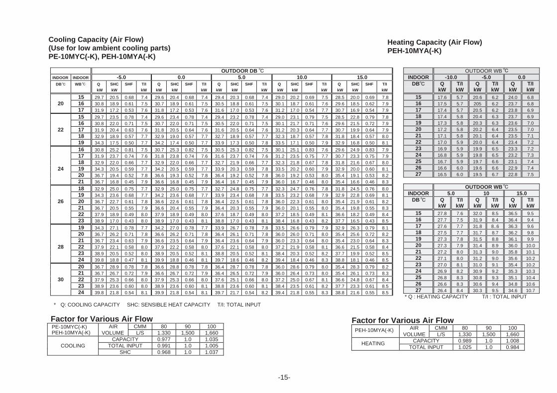
Cooling Capacity (Air Flow)PE-10MYC(-K), PEH-10MYA(-K)
PEH-10MYA(-K)PE-10MYC(-K)
-14-
DB WB Q
OUTDOOR DB INDOOR INDOOR -5.0 0.0 5.0 10.0 15.0
kW
SHC
kW
SHF T/I
kW
Q
kW
SHC
kW
SHF T/I
kW
Q
kW
SHC
kW
SHF T/I
kW
Q
kW
SHC
kW
SHF T/I
kW
Q
kW
SHC
kW
SHF T/I
kW
15 29.7 20.5 0.68 7.4 29.6 20.4 0.68 7.4 29.4 20.3 0.68 7.4 29.0 20.2 0.69 7.5 28.5 20.0 0.69 7.820 16 30.8 18.9 0.61 7.5 30.7 18.9 0.61 7.5 30.5 18.8 0.61 7.5 30.1 18.7 0.61 7.6 29.6 18.5 0.62 7.9
17 31.9 17.2 0.53 7.6 31.8 17.2 0.53 7.6 31.6 17.0 0.53 7.6 31.2 17.0 0.54 7.7 30.7 16.9 0.54 7.9
15 29.7 23.5 0.78 7.4 29.6 23.4 0.78 7.4 29.4 23.2 0.78 7.4 29.0 23.1 0.79 7.5 28.5 22.8 0.79 7.816 30.8 22.0 0.71 7.5 30.7 22.0 0.71 7.5 30.5 22.0 0.71 7.5 30.1 21.7 0.71 7.6 29.6 21.5 0.72 7.9
22 17 31.9 20.4 0.63 7.6 31.8 20.5 0.64 7.6 31.6 20.5 0.64 7.6 31.2 20.3 0.64 7.7 30.7 19.9 0.64 7.918 32.9 18.9 0.57 7.7 32.9 19.0 0.57 7.7 32.7 18.9 0.57 7.7 32.3 18.7 0.57 7.8 31.8 18.4 0.57 8.019 34.3 17.5 0.50 7.7 34.2 17.4 0.50 7.7 33.9 17.3 0.50 7.8 33.5 17.1 0.50 7.9 32.9 16.8 0.50 8.1
16 30.8 25.2 0.81 7.5 30.7 25.3 0.82 7.5 30.5 25.3 0.82 7.5 30.1 25.1 0.83 7.6 29.6 24.9 0.83 7.917 31.9 23.7 0.74 7.6 31.8 23.8 0.74 7.6 31.6 23.7 0.74 7.6 31.2 23.5 0.75 7.7 30.7 23.3 0.75 7.918 32.9 22.0 0.66 7.7 32.9 22.0 0.66 7.7 32.7 21.9 0.66 7.7 32.3 21.8 0.67 7.8 31.8 21.6 0.67 8.0
24 19 34.3 20.5 0.59 7.7 34.2 20.5 0.59 7.7 33.9 20.3 0.59 7.8 33.5 20.2 0.60 7.9 32.9 20.0 0.60 8.120 36.7 19.4 0.52 7.8 36.6 19.3 0.52 7.8 36.4 19.2 0.52 7.8 36.0 19.2 0.53 8.0 35.4 19.1 0.53 8.221 36.7 16.8 0.45 7.9 36.6 16.8 0.45 7.9 36.4 16.7 0.45 7.9 36.0 16.7 0.46 8.0 35.4 16.6 0.46 8.3
18 32.9 25.0 0.75 7.7 32.9 25.0 0.75 7.7 32.7 24.8 0.75 7.7 32.3 24.7 0.76 7.8 31.8 24.5 0.76 8.019 34.3 23.6 0.68 7.7 34.2 23.6 0.68 7.7 33.9 23.4 0.68 7.8 33.5 23.2 0.68 7.9 32.9 22.8 0.69 8.1
26 20 36.7 22.7 0.61 7.8 36.6 22.6 0.61 7.8 36.4 22.5 0.61 7.8 36.0 22.3 0.61 8.0 35.4 21.9 0.61 8.221 36.7 20.5 0.55 7.9 36.6 20.4 0.55 7.9 36.4 20.3 0.55 7.9 36.0 20.1 0.55 8.0 35.4 19.8 0.55 8.322 37.9 18.9 0.49 8.0 37.9 18.9 0.49 8.0 37.6 18.7 0.49 8.0 37.2 18.5 0.49 8.1 36.6 18.2 0.49 8.423 38.9 17.0 0.43 8.0 38.9 17.0 0.43 8.1 38.8 17.0 0.43 8.1 38.4 16.8 0.43 8.2 37.7 16.5 0.43 8.5
19 34.3 27.1 0.78 7.7 34.2 27.0 0.78 7.7 33.9 26.7 0.78 7.8 33.5 26.6 0.79 7.9 32.9 26.3 0.79 8.120 36.7 26.2 0.71 7.8 36.6 26.2 0.71 7.8 36.4 26.1 0.71 7.8 36.0 26.0 0.71 8.0 35.4 25.6 0.72 8.221 36.7 23.4 0.63 7.9 36.6 23.5 0.64 7.9 36.4 23.6 0.64 7.9 36.0 23.3 0.64 8.0 35.4 23.0 0.64 8.3
28 22 37.9 22.1 0.58 8.0 37.9 22.2 0.58 8.0 37.6 22.1 0.58 8.0 37.2 21.9 0.58 8.1 36.6 21.5 0.58 8.423 38.9 20.5 0.52 8.0 38.9 20.5 0.52 8.1 38.8 20.5 0.52 8.1 38.4 20.3 0.52 8.2 37.7 19.9 0.52 8.524 39.8 18.8 0.47 8.1 39.9 18.8 0.46 8.1 39.7 18.6 0.46 8.2 39.4 18.4 0.46 8.3 38.8 18.1 0.46 8.5
20 36.7 28.9 0.78 7.8 36.6 28.8 0.78 7.8 36.4 28.7 0.78 7.8 36.0 28.6 0.79 8.0 35.4 28.3 0.79 8.221 36.7 26.7 0.72 7.9 36.6 26.7 0.72 7.9 36.4 26.5 0.72 7.9 36.0 26.4 0.73 8.0 35.4 26.1 0.73 8.3
30 22 37.9 25.3 0.66 8.0 37.9 25.3 0.66 8.0 37.6 25.1 0.66 8.0 37.2 25.0 0.67 8.1 36.6 24.8 0.67 8.423 38.9 23.6 0.60 8.0 38.9 23.6 0.60 8.1 38.8 23.6 0.60 8.1 38.4 23.5 0.61 8.2 37.7 23.3 0.61 8.524 39.8 21.8 0.54 8.1 39.9 21.8 0.54 8.1 39.7 21.7 0.54 8.2 39.4 21.8 0.55 8.3 38.8 21.6 0.55 8.5
* Q: COOLING CAPACITY SHC: SENSIBLE HEAT CAPACITY T/I: TOTAL INPUT
Factor for Various Air FlowAIR CMM 80 90 100
VOLUME L/S 1.330 1,500 1,660CAPACITY 0.977 1.0 1.035
COOLING TOTAL INPUT 0.991 1.0 1.005SHC 0.968 1.0 1.037
OUTDOOR WBINDOOR -10.0 -5.0 0.0
DB QkW
T/IkW
QkW
T/IkW
QkW
T/IkW
15 17.6 5.7 20.6 6.2 24.0 6.816 17.5 5.7 205 6.2 23.7 6.817 17.4 5.7 20.5 6.2 23.8 6.918 17.4 5.8 20.4 6.3 23.7 6.919 17.3 5.8 20.3 6.3 23.6 7.020 17.2 5.8 20.2 6.4 23.5 7.021 17.1 5.8 20.1 6.4 23.5 7.122 17.0 5.9 20.0 6.4 23.4 7.223 16.9 5.9 19.9 6.5 23.3 7.224 16.8 5.9 19.8 6.5 23.2 7.325 16.7 5.9 19.7 6.6 23.1 7.426 16.6 6.0 19.6 6.6 22.9 7.427 16.5 6.0 19.5 6.7 22.8 7.5
OUTDOOR WBINDOOR 5.0 10 15.0
DB QkW
T/IkW
QkW
T/IkW
QkW
T/IkW
15 27.8 7.6 32.0 8.5 36.5 9.516 27.7 7.5 31.9 8.4 36.4 9.417 27.6 7.7 31.8 8..6 36.3 9.618 27.5 7.7 31.7 8.7 36.2 9.819 27.3 7.8 31.5 8.8 36.1 9.920 27.3 7.9 31.4 8.9 36.0 10.021 27.2 8.0 31.3 9.0 35.8 10.122 27.1 8.0 31.2 9.0 35.6 10.223 27.0 8.1 31.0 9.1 35.4 10.224 26.9 8.2 30.9 9.2 35.3 10.325 26.8 8.3 30.8 9.3 35.1 10.426 26.6 8.3 30.6 9.4 34.8 10.627 26.4 8.4 30.3 9.5 34.6 10.7
* Q : HEATING CAPACITY T/I : TOTAL INPUT
Cooling Capacity (Air Flow)(Use for low ambient cooling parts)PE-10MYC(-K), PEH-10MYA(-K)
Heating Capacity (Air Flow)PEH-10MYA(-K)
Factor for Various Air FlowAIR CMM 80 90 100
VOLUME L/S 1,330 1,500 1,660CAPACITY 0.989 1.0 1.008
TOTAL INPUT 1.025 1.0 0.984
PEH-10MYA(-K)PE-10MYC(-K)
HEATING
PEH-10MYA(-K)
-15-
DB WB Q
-16-
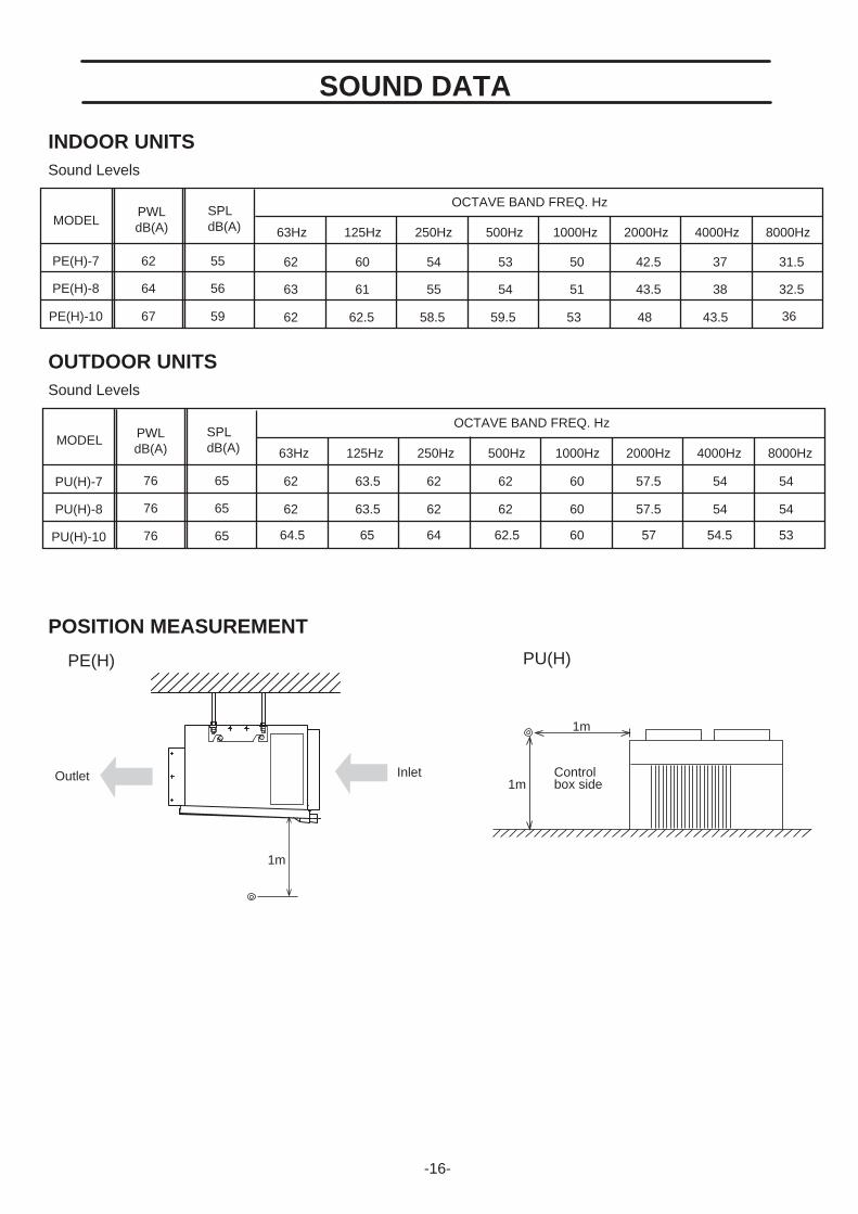
INDOOR UNITSSound Levels
OCTAVE BAND FREQ. HzMODEL
PWL SPL
63Hz 125Hz 250Hz 500Hz 1000Hz 2000Hz 4000Hz 8000Hz
55
56
59
62
63
62
60
61
62.5
54
55
58.5
53
54
59.5
50
51
53
42.5
43.5
48
37
38
43.5
31.5
32.5
36
62 63.5 62 62 60 57.5 54 54
62 63.5 62 62 60 57.5 54 54
64.5 65 64 62.5 60 57 54.5 53
OUTDOOR UNITS
POSITION MEASUREMENT
Sound Levels
SOUND DATA
InletOutlet
1m
1m
1m
Controlbox side
PE(H) PU(H)
PE(H)-7
PE(H)-8
PE(H)-10
dB(A)dB(A)
PWL SPLdB(A)dB(A)
62
64
67
OCTAVE BAND FREQ. HzMODEL
63Hz 125Hz 250Hz 500Hz 1000Hz 2000Hz 4000Hz 8000Hz
PU(H)-7
PU(H)-8
PU(H)-10
65
65
65
76
76
76

5048 55 60 65 70 72 75
Recommended Range
Internal SP
450
400
350
300
250
200
150
100
50
450
400
350
300
250
200
150
100
50
0
For Hi speed operation line
(Pa)
Tota
l sta
tic p
ress
ure
Air flow (m3/min)
Fan speed(rpm)
(Pa)Fan speed
(rpm)
(Pa)Fan speed
(rpm)
800
900
1000
1100
1200
1300
1400
PE(H)-7 PE(H)-8
50 55 60 65 70 75 80
Recommended Range
For Low speed operation line
Internal SP
0
Tota
l sta
tic p
ress
ure
Air flow (m3/min)
800
900
1000
1100
1200
1300
1400
Fan Performance Curve 50Hz
Fan Performance Curve 50Hz
Fan Performance Curve 50Hz
60 70 80 90 1000
Tota
l sta
tic p
ress
ure
Air flow (m3/min)
900
1000
1100
1200
1300
1400
800
Internal S
P
Recommended Range
For connection operation line
For connectionoperation line
For connection operation line
For connectionoperation line
450
400
350
300
250
200
150
100
50
-17-
FAN PERFORMANCE CURVE
PE(H)-10

-18-
PE(H)-7,8
PE(H)-10
OUTLINE DIMENSIONS
131
200
199
9515
215
6
AIR INLET DUCTFLANGE
HOLES:24- 3.1341102104
3113013013013013013013013031
344
20
419
1515
7050 530
130
130
4242
4040
HOLES:4- 12
280
70
DRAIN:1 BSP
CONTROL BOX
HOLES:22- 3.1
AIR OUTLET DUCTFLANGE
33 562
382
2510
010
025
1240
55
135
4095
20 201280
15
40
120
4513013013013013013013045
1415
40
1320
1000120
1264
9825
014
OPTIONAL PARTSCABLE ENTRY 27
AIR OUTLET
CONTROLCABLE ENTRY 27
AIR INLET
REFRIGERANT PIPE25.4
POWER SUPPLYCABLE ENTRY 27
REFRIGERANT PIPE15.88
4040
131
200
199
530
156
50
15 15
344
20
4242
130
130
419
HOLES:26- 3.1
AIR INLET DUCTFLANGE
341302104
6666 130130130130130130130130130
DRAIN:1 BSP
280
70
CONTROL BOX
HOLES:22- 3.1
AIR OUTLET DUCTFLANGE
9515
2
33 562
382
2510
010
025
701440
55
135
4095
20 201480
15
40
220
4513013013013013013013045
1615
40
1520
1000220
1464
9825
014
OPTIONAL PARTSCABLE ENTRY 27
AIR OUTLET
CONTROLCABLE ENTRY 27
AIR INLET
REFRIGERANT PIPE28.6
POWER SUPPLYCABLE ENTRY 27
REFRIGERANT PIPE15.88
HOLES:4- 12

-19-
PU(H)-7,8,10
28
18
120
235
175
100
2570025
540160122.5
108
980
875
25140025
700350
1372
4131000200CABLE ENTRY 25X40
REFRIGERANT PIPEPU(H)-7,8: 25.4PU(H)-10 : 28.6
REFRIGERANT PIPE15.88
SERVICING PANEL
HOLES 4-12x20
In the case of installation are shown below, it is possible to use the unit by connecting the dust.However, the pressure loss must be 30Pa (3mmAg) or less.Dust work is local supply.
Note:
622
DUCT DUCT

-20-
CR2
GRAY
CH
F3(3.15A)
52C
CZ30
49C
52C
15TB5
BLUE
CZ2
14
63H
51F2
CZ2
CZ30
51C
C5
C4
MC
123 BLACK
RED
MF3WHITE
52C 51C
321
51F2
WHITEMF2
REDRED
WHITE
BLACKBLACK
BLACK
WHITE
BLACK
WHITE
RED RED
RED
PU-7MYC
PE-7MYC
PE
3Phase50Hertz
Power supply,380 415Volt,
CIRCUIT BREAKER(FIELD SUPPLY) 100A
TB1L1
L2
L3
N
PE-7MYC (STANDARD)
OUTDOOR
CR1
26L
C3 3
C3 1
52F
FZ
FZ30 52F
BLUE
51F1
30FZ
CZ1
GRAY
GRAY
BLUE
BROWN
REDC1
C1
4
2
1
SW2(FIELD SUPPLY)
JUMPER
TB4TB4
6
7
5
Low
Hi
15
15
6
5
C
CZ2
14
TB3
14
(3.15A)
RED
BLUE
REDTB2L
N
4
CZ1
51F1
MF1
52F
F2
(3.15A)F1
24V
Tr
TB4
TB4
SWITCH BOX(FIELD SUPPLY)
1
SW1
2 3
FZ
PE
Single Phase50Hertz
Power supply,220 240Volt,
CIRCUIT BREAKER(FIELD SUPPLY) 15A
240V220AC AC
ConnectorSurge killer
Run capacitor
(compressor)Internal thermostat
CZ1, 2
C
CR1, 2
30CZ, FZ
Compressor motor
Terminal blockTB1 5
F1 3
Over current relay
Fan motor (outdoor)Contactor (compressor)
Over current relay(fanI/D,O/D)
Contactor (fan I/D)
Crankcase heater
TransformerFuse (3.15A)
Fan motor (indoor)
(compressor)
High-pressure switchThermostat (freeze protection)Auxiliary relay (fan)Auxiliary relay (compressor)Auxiliary relay (check)Switch (on)Switch (Fan Hi-Low)Thermostat (room temp.)
C1, C3 5
Note:1.The dotted lines show field wiring. 2.The figure in the parentheses show field supply parts. 3.Color of earth wire is yellow and green twisting. 4.Not specified color of wire is brown.
5.Please remove the jumper wire ( Mark) in the above diagram if you use the Switch <SW2> at local.
If the Switch <SW2> is not used, the Fan motor (indoor) drives at high speed.
6.Specification subject to change without notice.
Y124V
Power (Neutral)Fan operation
Local controller'sterminal no.
24V(C)G
Cooling operationPower (Active)
4321
Function
Local controller connection.(Ex.Type SHP-1)
No.
TB4
Symbol
Caution,1.To protect each Fan motor and Compressor from abnormal current, Over current relays <51C>, <51F1,2> are installed. Therefore, do not change factory set value of Over current relays.
23WA
WIRING DIAGRAMS

-21-
CR2
GRAY
CH
F3(3.15A)
F1(3.15A)
(3.15A)
52C
CZ30
49C
52C
15TB5
BLUE
CZ2
14
63H
51F2
CZ2
CZ30
51C
C5
C4
MC
123 BLACK
RED
MF3WHITE
52C 51C
321
51F2
WHITEMF2
REDRED
WHITE
BLACKBLACK
BLACK
WHITE
BLACK
WHITE
RED RED
RED
PU-8, 10MYC
PE
3Phase50Hertz
Power supply,380 415Volt,
CIRCUIT BREAKER(FIELD SUPPLY) 100A
TB1L1
L2
L3
N
AccessoryThis circuit diagram shows connections.(If the external static Pressure is lessthan 30 Pa, change to connections.)
Note:1.The dotted lines show field wiring. 2.The figure in the parentheses show field supply parts. 3.Color of earth wire is yellow and green twisting. 4.Not specified color of wire is brown. 5.Specification subject to change without notice.
Caution,1.To protect each Fan motor and Compressor from abnormal current, Over current relays <51C>, <51F1,2> are installed. Therefore, do not change factory set value of Over current relays.
PE-8,10MYC (STANDARD)
OUTDOOR
CR1
26L
3C3
C3 1
5
4
C1
C1
51F1
49F
BLUEN
24V240V
AC220AC
Tr
TB4
TB4
SWITCH BOX(FIELD SUPPLY)
SW1
2 3
FZ
F2
CZ1
30FZ
52F
52F
14
RED
4
GRAY
15
FZ
15
GRAY
14
FZ30
CZ2
BLUE
23WA
TB3
CZ1
C2C1
321
1
BLUE
WHITE
RED
3
12
BLACK
WHITE
REDTB2
L1L2L3 BLUE
RED51F1
MF1WHITE
52F
PE-8,10MYC
PE
3Phase50Hertz
Power supply,380 415Volt,
CIRCUIT BREAKER(FIELD SUPPLY) 15A
Connector
(indoor fan)(compressor)Internal thermostat
Internal thermostat 49F
CZ1, 2
Surge killerCR1, 2
30CZ, FZ
Compressor motor
Terminal blockTB1 5
F1 3
Over current relay
Fan motor (outdoor)Contactor (compressor)
Over current relay(fanI/D,O/D)
Contactor (fan I/D)
Crankcase heater
TransformerFuse (3.15A)
Fan motor (indoor)
(compressor)
High-pressure switchThermostat (freeze protection)Auxiliary relay (fan)Auxiliary relay (compressor)Auxiliary relay (check)Switch (on)Thermostat (room temp.)
C1 5
Y124V
Power (Neutral)Fan operation
Local controller'sterminal no.
24V(C)G
Cooling operationPower (Active)
4321
Function
Local controller connection.(Ex.Type SHP-1)
No.
TB4
Symbol

-22-
CR2
GRAY
CH
F3(3.15A)
(3.15A)
52C
CZ30
49C
52C
15TB5
BLUE
CZ2
14
63H
51F2
CZ2
CZ30
51C
C5
C4
MC
123 BLACK
RED
MF3WHITE
52C 51C
321
51F2
WHITEMF2
REDRED
WHITE
BLACKBLACK
BLACK
WHITE
BLACK
WHITE
RED REDRED
PU-7MYC
PE
3Phase50Hertz
Power supply,380 415Volt,
CIRCUIT BREAKER(FIELD SUPPLY) 100A
TB1L1
L2
L3
N
PE-7MYC-K (STANDARD)
AC24V
OUTDOOR
CN22 CN21
CN4TCN20 CN30 M3M2 M0 S R(TRANS)
R/C
A B C D
CR1
CZ1
F2(3.15A)
CZ2
14 15
14 15
52F
TB3
30FZ
30FZ 52F
FZ
CZ1
1C1
BLUEMF1
RED C15
6 C
BLUE
REDF1
51F1
4
52F
BLUE
RED
N
TB2L
Blue
Green/Yellow
Blue
DSACN
13
51F1
TH2
IB
Tr
TH5
FZ
PE-7MYC-K
PE
Single Phase50Hertz
Power supply,220 240Volt,
CIRCUIT BREAKER(FIELD SUPPLY) 15A
Surge absorber circuit boardRemote controller
(compressor)Internal thermostat
CZ1, 2
IBTH2
Run capacitorConnector
C
Surge killerCR1, 2
30CZ, FZ
Compressor motor
Terminal blockTB1 3, 5
F1 3
Over current relay
Fan motor (outdoor)Contactor (compressor)
Over current relay(fanI/D,O/D)
Contactor (fan I/D)
Crankcase heater
TransformerFuse (3.15A)
Fan motor (indoor)
(compressor)
High-pressure switchAuxiliary relay (fan)Auxiliary relay (compressor)Auxiliary relay (check)Indoor boardThermistor (pipe)
TH5R/CDSA
Thermistor (room temp.)
Note:1.The dotted lines show field wiring. 2.The figure in the parentheses show field supply parts. 3.Color of earth wire is yellow and green twisting. 4.Not specified color of wire is brown. 5.Specification subject to change without notice.
Caution,1.To protect each Fan motor and Compressor from abnormal current, Over current relays <51C>, <51F1,2> are installed. Therefore, do not change factory set value of Over current relays.
C1,4 5

-23-
CR2
GRAY
CH
F3(3.15A)
(3.15A)
52C
CZ30
49C
52C
15TB5
BLUE
CZ2
14
63H
51F2
CZ2
CZ30
51C
C5
C4
MC
123 BLACK
RED
MF3WHITE
52C 51C
321
51F2
WHITEMF2
REDRED
WHITE
BLACKBLACK
BLACK
WHITE
BLACK
WHITE
RED REDRED
PU-8, 10MYC
PE
3Phase50Hertz
Power supply,380 415Volt,
CIRCUIT BREAKER(FIELD SUPPLY) 100A
TB1L1
L2
L3
N
Surge absorber circuit boardRemote controller
(indoor fan)(compressor)Internal thermostat
Internal thermostat 49F
CZ1, 2
IBTH2
ConnectorC1,2,4,5 Surge killerCR1, 2
30CZ, FZ
Compressor motor
Terminal blockTB1 3, 5
F1 3
Over current relay
Fan motor (outdoor)Contactor (compressor)
Over current relay(fanI/D,O/D)
Contactor (fan I/D)
Crankcase heater
TransformerFuse (3.15A)
Fan motor (indoor)
(compressor)
High-pressure switchAuxiliary relay (fan)Auxiliary relay (compressor)Auxiliary relay (check)Indoor boardThermistor (pipe)
TH5R/CDSA
Thermistor (room temp.)
AccessoryThis circuit diagram shows connections.(If the external static Pressure is lessthan 30 Pa, change to connections.)
Note:1.The dotted lines show field wiring. 2.The figure in the parentheses show field supply parts. 3.Color of earth wire is yellow and green twisting. 4.Not specified color of wire is brown. 5.Specification subject to change without notice.
Caution,1.To protect each Fan motor and Compressor from abnormal current, Over current relays <51C>, <51F1,2> are installed. Therefore, do not change factory set value of Over current relays.
AC24V
A B C D
CN22 CN21
CN4TCN20 CN30 M3M2 M0 S R(TRANS)
R/C
CR1
C1
C14
49F
5
CZ1
F2(3.15A)
52F
TB3
30FZ
52F
FZTr
TH5
FZ
51F1TH2
IB
F1
CZ2
14 15
14 15
30FZ
CZ1
BLUE
BLUE
RED
MF1WHITE
BLUE
WHITE
RED
3
12
321C1 C2
N Blue
13
DSACN Blue
RED
Green/Yellow
52F 51F1
L3L2
RED
WHITE
BLACK
OUTDOOR
TB2L1
PE-8, 10MYC-K
PE
3Phase50Hertz
Power supply,380 415Volt,
CIRCUIT BREAKER(FIELD SUPPLY) 15A
PE-8,10MYC-K (STANDARD)

-24-
PE-7MYC(SPECIAL ORDER :ANTI SHORT CYCLE TIMER)
OUTDOOR
TM(3MIN)
TM
CR1
CR2
GRAY
26L
C3 3
C3 1
CH
52F
HZ1
FZ
FZ30 52F
BLUE
51F1
30FZ
F3(3.15A)
51C
63H
51F2
CZ2
CZ30
CZ30
52C
CZ1
15
CZ2
14
49C
52C
GRAY
GRAY
BLUE
BROWN
REDC1
C1
4
2
1
SW3(FIELD SUPPLY)
JUMPER
TB4TB4
7
8
6
Low
Hi
C5
C4
15
15
6
5
RED
MC
321
C
BLACK
WHITEMF3
CZ2
14
TB3
52C
14
BLUE
(3.15A)
RED
BLUE
REDTB2L
N
4
51C
321
51F2
CZ1
WHITE
51F1
MF1
52F
X1
MF2
REDRED
WHITE
BLACKBLACK
BLACK
F2
WHITE
BLACK
WHITE
RED RED
RED
TB1L1
L2
L3
N
TB5
(3.15A)F1
Tr
TB4
TB4
SWITCH BOX(FIELD SUPPLY)
1
2 3
FZ
PU-7MYC
3Phase50Hertz
Power supply,380 415Volt,
CIRCUIT BREAKER(FIELD SUPPLY) 100A
Single Phase50Hertz
Power supply,220 240Volt,
220240V 24V
ACAC
PE
PE
PE-7MYA CIRCUIT BREAKER(FIELD SUPPLY) 15A
ConnectorSurge killer
Run capacitor
(compressor)Internal thermostat
CZ1, 2
C
CR1, 2Timer (Anti short cycle)TM
30CZ, FZ
Compressor motor
Terminal blockTB1 5
F1 3
Over current relay
Fan motor (outdoor)Contactor (compressor)
Over current relay(fanI/D,O/D)
Contactor (fan I/D)
Crankcase heater
TransformerFuse (3.15A)
Fan motor (indoor)
(compressor)
High-pressure switchThermostat (freeze protection)Auxiliary relay (fan)Auxiliary relay (compressor)Auxiliary relay (check)Switch (on)Switch (Fan Hi-Low)Thermostat (room temp.)
C1, C3 5
Note:1.The dotted lines show field wiring. 2.The figure in the parentheses show field supply parts. 3.Color of earth wire is yellow and green twisting. 4.Not specified color of wire is brown.
5.Please remove the jumper wire ( Mark) in the above diagram if you use the Switch <SW2> at local.
If the Switch <SW2> is not used, the Fan motor (indoor) drives at high speed.
6.Specification subject to change without notice.
Y124V
Power (Neutral)Fan operation
Local controller'sterminal no.
24V(C)G
Cooling operationPower (Active)
4321
Function
Local controller connection.(Ex.Type SHP-1)
No.
TB4
Symbol
Caution,1.To protect each Fan motor and Compressor from abnormal current, Over current relays <51C>, <51F1,2> are installed. Therefore, do not change factory set value of Over current relays.
SW1
23WA

-25-
OUTDOOR
(3MIN)TM
TM
CR1
CR2
26L
GRAY
X1
3C3
C3 1
5
4
C1
C1
49F
51F1
CH
BLUE
F3(3.15A)
(3.15A)
F3(3.15A)
52C
CZ30
49C
52C
15TB5
BLUE
CZ2
14
63H
51F2
CZ2
CZ30
51C
220240V
24VACAC
Tr
TB4
TB4
2 3
FZ
F2
CZ1
30FZ
52F
52F
HZ1
14
RED
4
GRAY
15
FZ
15
GRAY
14
FZ30
CZ2
BLUE
TB3
CZ1
C2C1
321
1
BLUE
WHITE
RED
C5
C4
MC
3
12
123 BLACK
RED
MF3WHITE
52C
BLACK
WHITE
RED
51C
321
51F2
WHITE
BLUE
RED51F
MF1WHITE
52F
MF2
REDRED
WHITE
BLACKBLACK
BLACK
WHITE
BLACK
WHITE
RED REDRED
PU-8, 10MYC
PE
3Phase50Hertz
Power supply,380 415Volt,
CIRCUIT BREAKER(FIELD SUPPLY) 100A
TB1L1
L2
L3
N
PEH-8, 10MYA
3Phase50Hertz
Power supply,380 415Volt,
CIRCUIT BREAKER(FIELD SUPPLY) 15A
TB1L1L2L3
N
PE
PE-8,10MYC(SPECIAL ORDER :ANTI SHORT CYCLE TIMER.)
AccessoryThis circuit diagram shows connections.(If the external static Pressure is lessthan 30 Pa, change to connections.)
Note:1.The dotted lines show field wiring. 2.The figure in the parentheses show field supply parts. 3.Color of earth wire is yellow and green twisting. 4.Not specified color of wire is brown. 5.Specification subject to change without notice.
Caution,1.To protect each Fan motor and Compressor from abnormal current, Over current relays <51C>, <51F1,2> are installed. Therefore, do not change factory set value of Over current relays.
Connector
(indoor fan)(compressor)Internal thermostat
Internal thermostat 49F
CZ1, 2
Surge killerCR1, 2Timer (Anti short cycle)TM
30CZ, FZ
Compressor motor
Terminal blockTB1 5
F1 3
Over current relay
Fan motor (outdoor)Contactor (compressor)
Over current relay(fanI/D,O/D)
Contactor (fan I/D)
Crankcase heater
TransformerFuse (3.15A)
Fan motor (indoor)
(compressor)
High-pressure switchThermostat (freeze protection)Auxiliary relay (fan)Auxiliary relay (compressor)Auxiliary relay (check)Switch (on)Thermostat (room temp.)
C1 5
Y124V
Power (Neutral)Fan operation
Local controller'sterminal no.
24V(C)G
Cooling operationPower (Active)
4321
Function
Local controller connection.(Ex.Type SHP-1)
No.
TB4
Symbol
SWITCH BOX(FIELD SUPPLY)
SW1
23WA

-26-
Note:1.The dotted lines show field wiring. 2.The figure in the parentheses show field supply parts. 3.Color of earth wire is yellow and green twisting. 4.Not specified color of wire is brown.
5.Please remove the jumper wire ( Mark) in the above diagram if you use the Switch <SW2> at local.
If the Switch <SW2> is not used, the Fan motor (indoor) drives at high speed.
6.Specification subject to change without notice.
Caution,1.To protect each Fan motor and Compressor from abnormal current, Over current relays <51C>, <51F1,2> are installed. Therefore, do not change factory set value of Over current relays.
H
OUTDOOR
53
23C1
132C7
2C6
1C6
52F3
52F2
BLACK
WHITE
RED
52F449F
F252
F352
52F4 52F2
52F1
52F3
CR1
CR2
GRAY
26L
C3 3
C3 1
CH
52F1
FZ
FZ30
BLUE
51F1
30FZ
F3(3.15A)
51C
63H
51F2
CZ2
CZ30
CZ30
52C
CZ1
15
CZ2
14
49C
52C
PE-7MYC
PU-7MYC
PE
GRAY
GRAY
BLUE
BROWN
REDC1
C1
4
2
1
SW2(FIELD SUPPLY)
JUMPER
TB4TB4
6
7
5
Low
Hi
C5
C4
15
15
6
5
RED
MC
321
C
BLACK
WHITEMF3
Single Phase220 240Volt,50HertzPower Supply,
3Phase50Hertz
Power supply,380 415Volt,
CZ2
14
TB3
52C
14
CIRCUIT BREAKER(FIELD SUPPLY) 15A
BLUE
(3.15A)
RED
BLUE
REDTB2L
N
4
CIRCUIT BREAKER(FIELD SUPPLY) 100A
51C
32151F2
CZ1
WHITE
51F1
MF1
52F1
MF2
REDRED
WHITE
BLACKBLACK
BLACK
F2
WHITE
BLACK
WHITE
RED REDRED
TB1L1
L2
L3
N
TB5
(3.15A)F1
23WA
220240V
24VAC
AC
Tr
TB4
TB4
SWITCH BOX(FIELD SUPPLY)
1
SW1
2 3
FZ
PE
Y124V
Power (Neutral)Fan operation
Local controller'sterminal no.
24V(C)G
Cooling operationPower (Active)
4321
Function
Local controller connection.(Ex.Type SHP-1)
No.
TB4
Symbol
PE-7MYC(SPECIAL ORDER :LOW AMBIENT COOLING)
Run capacitorConnector
(compressor)Internal thermostat Internal thermostat(fan O/D)
F1 3Tr
49F
52F1
23C
CZ1, 2
C
Surge killerCR1, 2C1, 3 7
30CZ, FZ
Compressor motor
52F2 4
TB1 5
Over current relay
Fan motor (outdoor)Contactor (compressor)
Over current relay(fanI/D,O/D)
Contactor (fan I/D)Contactor (fan O/D)Ambient temperature
Fuse (3.15A)CH Crankcase heater
Terminal block
Fan motor (indoor)
(compressor)
High-pressure switchThermostat (freeze protection)Auxiliary relay (fan)Auxiliary relay (compressor)Auxiliary relay (check)Switch (on)Switch (Fan Hi-Low)Thermostat (room temp.)
Transformer

-27-
Note:1.The dotted lines show field wiring. 2.The figure in the parentheses show field supply parts. 3.Color of earth wire is yellow and green twisting. 4.Not specified color of wire is brown. 5.Specification subject to change without notice.
Caution,1.To protect each Fan motor and Compressor from abnormal current, Over current relays <51C>, <51F1,2> are installed. Therefore, do not change factory set value of Over current relays.
Y124V
Power (Neutral)Fan operation
Local controller'sterminal no.
24V(C)G
Cooling operationPower (Active)
4321
Function
Local controller connection.(Ex.Type SHP-1)
No.
TB4
Symbol
H
OUTDOOR
1
132C7
2C6
C6
49F2
1
52F352F252F4
52F3
52F2
3 5
23C
BLACK
RED
MF2WHITE
123
MF3WHITE
BLACK
123
MC
RED
C4
C5
52F4
RED
WHITE
BLACK
52F2
52F3
CR1
CR2
26L
GRAY
3C3
C3 1
5
4
C1
C1
49F1
51F1
CH
BLUEN
F3(3.15A)
F1(3.15A)
(3.15A)
52C
CZ30
49C
52C
N
15TB5
BLUE
CZ2
14
63H
51F2
CZ2
CZ30
51C
PE
PE
220240V
24VACAC
Tr
TB4
TB4
SWITCH BOX(FIELD SUPPLY)
SW1
2 3
FZ
F2
CZ1
30FZ
52F1
14
RED
4
GRAY
15
FZ
15
GRAY
14
FZ30
CZ2
BLUE
TB3
CZ1
PU-8,10MYC
C2C1
321
1
BLUE
WHITE
RED
3
12
52C
BLACK
WHITE
RED
TB2L1L2L3
CIRCUIT BREAKER(FIELD SUPPLY)100A
PE-8,10MYC CIRCUIT BREAKER(FIELD SUPPLY)15A
51C
51F2
BLUE
RED51F
MF1WHITE
52F1
RED
WHITE
BLACK
BLACK
WHITE
BLACK
WHITE
RED REDRED
TB1L1
L2
L3
Power Supply,50Hertz380 415Volt,3Phase
Power Supply,50Hertz380 415Volt,3Phase
PE-8,10MYC(SPECIAL ORDER :LOW AMBIENT COOLING)
52F1
23WA
Connector
(compressor)(outdoor fan)(indoor fan)
Internal thermostat Internal thermostat
F1 3Tr
49F2Internal thermostat 49F1
52F1
23C
CZ1, 2
Surge killerCR1, 2C1 7
30CZ, FZ
Compressor motor
52F2 4
TB1 5
Over current relay
Fan motor (outdoor)Contactor (compressor)
Over current relay(fanI/D,O/D)
Contactor (fan I/D)Contactor (fan O/D)Ambient temperature
Fuse (3.15A)CH Crankcase heater
Terminal block
Fan motor (indoor)
(compressor)
High-pressure switchThermostat (freeze protection)Auxiliary relay (fan)Auxiliary relay (compressor)Auxiliary relay (check)Switch (on)Thermostat (room temp.)
Transformer
AccessoryThis circuit diagram shows connections.(If the external static Pressure is lessthan 30 Pa, change to connections.)

-28-
CR2
GRAY
X1
X1
C63
C61
1
3C7
CH
F3(3.15A)
X1 X2
52C
CZ30
C7
26D2
21T1 S4
26D1 X2
X3
X1 X2X3 T149C
52C
1315
HZ2
TB5
BLUE
CZ2
14
63H
51F2
CZ2
CZ30
51C
HZ2
C5
C4
MC
123 BLACK
RED
MF3WHITE
52C 51C
321
51F2
WHITEMF2
REDRED
WHITE
BLACKBLACK
BLACK
WHITE
BLACK
WHITE
RED RED
RED
PUH-7MYC
PEH-7MYA
PE
3Phase50Hertz
Power supply,380 415Volt,
CIRCUIT BREAKER(FIELD SUPPLY) 100A
TB1L1
L2
L3
N
PEH-7MYA (STANDARD)
OUTDOOR
CR1
26L
C3 3
C3 1
52F
HZ1
FZ
FZ30 52F
BLUE
51F1
30FZ
CZ1
HZ2
GRAY
GRAY
BLUE
BROWN
REDC1
C1
4
2
1
SW3(FIELD SUPPLY)
JUMPER
TB4TB4
7
8
6
Low
Hi
15
15
6
5
C
CZ2
13
14
TB3
14
13
(3.15A)
RED
BLUE
REDTB2L
N
5
23WA
CZ1
51F1
MF1
52F
F2
HC
(3.15A)F1
SW1
HEATCOOL
24V
Tr
HZ1
3TB4
TB4
SWITCH BOX(FIELD SUPPLY)
1
SW2
2 4
FZ
HZ1PE
Single Phase50Hertz
Power supply,220 240Volt,
CIRCUIT BREAKER(FIELD SUPPLY) 15A
240V220AC
Auxiliary relay (defrost)Contactor (fan O/D)
T1 Timer (defrost)ConnectorRun capacitor
(compressor)Internal thermostat
CZ1, 2HZ1, 2
C
3
Surge killerCR1, 2
30CZ, FZ
Compressor motor
Terminal blockTB1 5
F1 3
Over current relay
Fan motor (outdoor)Contactor (compressor)
Over current relay(fanI/D,O/D)
Contactor (fan I/D)
Crankcase heater
TransformerFuse (3.15A)
Fan motor (indoor)
(compressor)
High-pressure switch
Thermostat (defrost)Thermostat (freeze protection)
Auxiliary relay (fan)Auxiliary relay (compressor)Auxiliary relay (4-way valve)Auxiliary relay (check)
Switch (operation mode)Switch (on)Switch (Fan Hi-Low)Thermostat (room temp.)
4-Way valve
C1, C3 7
Note:1.The dotted lines show field wiring. 2.The figure in the parentheses show field supply parts. 3.Color of earth wire is yellow and green twisting. 4.Not specified color of wire is brown.
5.Please remove the jumper wire ( Mark) in the above diagram if you use the Switch <SW3> at local.
If the Switch <SW3> is not used, the Fan motor (indoor) drives at high speed.
6.Specification subject to change without notice.
Y124V
Power (Neutral)Fan operation
Local controller'sterminal no.
24V(C)G
Cooling or Heating operationReversing valve for Heating operation
Power (Active)
54321
B
Function
Local controller connection.(Ex.Type SHP-1)
No.
TB4
Symbol
Caution,1.To protect each Fan motor and Compressor from abnormal current, Over current relays <51C>, <51F1,2> are installed. Therefore, do not change factory set value of Over current relays.

-29-
CR2
GRAY
X1
X1
C63
C61
1
3C7
CH
F3(3.15A)
F1(3.15A)
(3.15A)
X1 X2
52C
CZ30
C7
26D2
21T1 S4
26D1 X2
X3
X1 X2X3 T149C
52C
1315
HZ2
TB5
BLUE
CZ2
14
63H
51F2
CZ2
CZ30
51C
HZ2
C5
C4
MC
123 BLACK
RED
MF3WHITE
52C 51C
321
51F2
WHITEMF2
REDRED
WHITE
BLACKBLACK
BLACK
WHITE
BLACK
WHITE
RED RED
RED
PUH-8, 10MYC
PE
3Phase50Hertz
Power supply,380 415Volt,
CIRCUIT BREAKER(FIELD SUPPLY) 100A
TB1L1
L2
L3
N
AccessoryThis circuit diagram shows connections.(If the external static Pressure is lessthan 30 Pa, change to connections.)
Note:1.The dotted lines show field wiring. 2.The figure in the parentheses show field supply parts. 3.Color of earth wire is yellow and green twisting. 4.Not specified color of wire is brown. 5.Specification subject to change without notice.
Caution,1.To protect each Fan motor and Compressor from abnormal current, Over current relays <51C>, <51F1,2> are installed. Therefore, do not change factory set value of Over current relays.
PEH-8,10MYA (STANDARD)
OUTDOOR
CR1
26L
3C3
C3 1
5
4
C1
C1
51F1
49F
BLUEN
24V240V
AC220AC
Tr
HZ1
3TB4
TB4
SWITCH BOX(FIELD SUPPLY)
SW2
2 4
FZ
HC
HZ1
F2
CZ1
30FZ
52F
52F
HZ1
14
RED
5
13
GRAY
SW1
HEATCOOL 15
FZ
15
GRAY
HZ2
14
FZ30
CZ2
BLUE
23WA
TB3
CZ1
13
C2C1
321
1
BLUE
WHITE
RED
3
12
BLACK
WHITE
REDTB2
L1L2L3 BLUE
RED51F
MF1WHITE
52F
PEH-8,10MYA
PE
3Phase50Hertz
Power supply,380 415Volt,
CIRCUIT BREAKER(FIELD SUPPLY) 15A
Auxiliary relay (defrost)Contactor (fan O/D)
T1 Timer (defrost)Connector
(indoor fan)(compressor)Internal thermostat
Internal thermostat 49F
CZ1, 2HZ1, 2
Surge killerCR1, 2
30CZ, FZ
Compressor motor
Terminal blockTB1 5
F1 3
Over current relay
Fan motor (outdoor)Contactor (compressor)
Over current relay(fanI/D,O/D)
Contactor (fan I/D)
Crankcase heater
TransformerFuse (3.15A)
Fan motor (indoor)
(compressor)
High-pressure switch
Thermostat (defrost)Thermostat (freeze protection)
Auxiliary relay (fan)Auxiliary relay (compressor)Auxiliary relay (4-way valve)Auxiliary relay (check)
Switch (operation mode)Switch (on)Thermostat (room temp.)
4-Way valve
C1 7
Y124V
Power (Neutral)Fan operation
Local controller'sterminal no.
24V(C)G
Cooling or Heating operationReversing valve for Heating operation
Power (Active)
54321
B
Function
Local controller connection.(Ex.Type SHP-1)
No.
TB4
Symbol

-30-
CR2
GRAY
X1
X1
C63
C61
1
3C7
CH
F3(3.15A)
(3.15A)
X1 X2
52C
CZ30
C7
26D2
21T1 S4
26D1 X2
X3
X1 X2X3 T149C
52C
1315
HZ2
TB5
BLUE
CZ2
14
63H
51F2
CZ2
CZ30
51C
HZ2
C5
C4
MC
123 BLACK
RED
MF3WHITE
52C 51C
321
51F2
WHITEMF2
REDRED
WHITE
BLACKBLACK
BLACK
WHITE
BLACK
WHITE
RED REDRED
PUH-7MYC
PE
3Phase50Hertz
Power supply,380 415Volt,
CIRCUIT BREAKER(FIELD SUPPLY) 100A
TB1L1
L2
L3
N
Auxiliary relay (defrost)Contactor (fan O/D)
Timer (defrost)
Surge absorber circuit boardRemote controller
(compressor)Internal thermostat
CZ1, 2
IBTH2
HZ1, 2
ConnectorC1,4 7 Run capacitorC
T1 Surge killerCR1, 2
30CZ, FZ
Compressor motor
Terminal blockTB1 3, 5
F1 3
Over current relay
Fan motor (outdoor)Contactor (compressor)
Over current relay(fanI/D,O/D)
Contactor (fan I/D)
Crankcase heater
TransformerFuse (3.15A)
Fan motor (indoor)
(compressor)
High-pressure switchThermostat (defrost)
Auxiliary relay (fan)Auxiliary relay (compressor)Auxiliary relay (4way valve)Auxiliary relay (check)
Indoor boardThermistor (pipe)
TH5R/CDSA
Thermistor (room temp.)
4-Way valve
Note:1.The dotted lines show field wiring. 2.The figure in the parentheses show field supply parts. 3.Color of earth wire is yellow and green twisting. 4.Not specified color of wire is brown. 5.Specification subject to change without notice.
Caution,1.To protect each Fan motor and Compressor from abnormal current, Over current relays <51C>, <51F1,2> are installed. Therefore, do not change factory set value of Over current relays.
PEH-7MYA-K (STANDARD)
AC24V
OUTDOOR
CN22 CN21
CN4TCN20 CN30 M3M2 M0 S R(TRANS)
R/C
A B C D
CR1
CZ1 HZ1
F2(3.15A)
CZ2
HZ2
14 15 13
14 15 13
52F
TB3
30FZ
30FZ 52F
FZ
HZ1
CZ1
1C1
BLUEMF1
RED C15
6 C
BLUE
REDF1
51F1
4
52F
BLUE
RED
N
TB2L
Blue
Green/Yellow
Blue
DSACN
13
51F1
TH2
IB
Tr
TH5
FZ
PEH-7MYA-K
PE
Single Phase50Hertz
Power supply,220 240Volt,
CIRCUIT BREAKER(FIELD SUPPLY) 15A

-31-
CR2
GRAY
X1
X1
C63
C61
1
3C7
CH
F3(3.15A)
(3.15A)
X1 X2
52C
CZ30
C7
26D2
21T1 S4
26D1 X2
X3
X1 X2X3 T149C
52C
1315
HZ2
TB5
BLUE
CZ2
14
63H
51F2
CZ2
CZ30
51C
HZ2
C5
C4
MC
123 BLACK
RED
MF3WHITE
52C 51C
321
51F2
WHITEMF2
REDRED
WHITE
BLACKBLACK
BLACK
WHITE
BLACK
WHITE
RED REDRED
PUH-8, 10MYC
PE
3Phase50Hertz
Power supply,380 415Volt,
CIRCUIT BREAKER(FIELD SUPPLY) 100A
TB1L1
L2
L3
N
Auxiliary relay (defrost)Contactor (fan O/D)
Timer (defrost)
Surge absorber circuit boardRemote controller
(indoor fan)(compressor)Internal thermostat
Internal thermostat 49F
CZ1, 2
IBTH2
HZ1, 2
ConnectorC1,2,4 7 T1
Surge killerCR1, 2
30CZ, FZ
Compressor motor
Terminal blockTB1 3, 5
F1 3
Over current relay
Fan motor (outdoor)Contactor (compressor)
Over current relay(fanI/D,O/D)
Contactor (fan I/D)
Crankcase heater
TransformerFuse (3.15A)
Fan motor (indoor)
(compressor)
High-pressure switchThermostat (defrost)
Auxiliary relay (fan)Auxiliary relay (compressor)Auxiliary relay (4-way valve)Auxiliary relay (check)
Indoor boardThermistor (pipe)
TH5R/CDSA
Thermistor (room temp.)
4-Way valve
AccessoryThis circuit diagram shows connections.(If the external static Pressure is lessthan 30 Pa, change to connections.)
Note:1.The dotted lines show field wiring. 2.The figure in the parentheses show field supply parts. 3.Color of earth wire is yellow and green twisting. 4.Not specified color of wire is brown. 5.Specification subject to change without notice.
Caution,1.To protect each Fan motor and Compressor from abnormal current, Over current relays <51C>, <51F1,2> are installed. Therefore, do not change factory set value of Over current relays.
AC24V
A B C D
CN22 CN21
CN4TCN20 CN30 M3M2 M0 S R(TRANS)
R/C
CR1
C1
C14
49F
5
CZ1 HZ1
F2(3.15A)
52F
TB3
30FZ
52F
FZTr
TH5
FZ
51F1TH2
IB
F1
CZ2
HZ2
14 15 13
14 15 13
30FZ
HZ1
CZ1
BLUE
BLUE
RED
MF1WHITE
BLUE
WHITE
RED
3
12
321C1 C2
N Blue
13
DSACN
Blue
Green/Yellow
52F 51F1
L3L2
RED
WHITE
BLACK
OUTDOOR
TB2L1
PEH-8, 10MYA-K
PE
3Phase50Hertz
Power supply,380 415Volt,
CIRCUIT BREAKER(FIELD SUPPLY) 15A
PEH-8,10MYA-K (STANDARD)

-32-
Auxiliary relay (defrost)Contactor (fan O/D)
Timer (Anti short cycle)TM
T1 Timer (defrost)ConnectorRun capacitor
(compressor)Internal thermostat
CZ1, 2HZ1, 2
C
3
Surge killerCR1, 2
30CZ, FZ
Compressor motor
Terminal blockTB1 5
F1 3
Over current relay
Fan motor (outdoor)Contactor (compressor)
Over current relay(fanI/D,O/D)
Contactor (fan I/D)
Crankcase heater
TransformerFuse (3.15A)
Fan motor (indoor)
(compressor)
High-pressure switch
Thermostat (defrost)Thermostat (freeze protection)
Auxiliary relay (fan)Auxiliary relay (compressor)Auxiliary relay (4-way valve)Auxiliary relay (check)
Switch (operation mode)Switch (on)Switch (Fan Hi-Low)Thermostat (room temp.)
4-Way valve
C1, 3 7
PEH-7MYA(SPECIAL ORDER :ANTI SHORT CYCLE TIMER., PROTECT FOR COOL AIR BLOW.)
OUTDOOR
OUTDOOR
TM(3MIN)
TM
X3
16
17
16
16
X3
17
17
CR1
CR2
GRAY
X1
26L
C3 3
C3 1
3C6
1C6
C73
CH
52F
HZ1
FZ
FZ30 52F
BLUE
51F1
30FZ
F3(3.15A)
51C
63H
51F2
CZ2
CZ30
CZ30
52C
CZ1
HZ2
1315
HZ2CZ2
14
C71
26D2
21T1 S4
26D1
X1 X2
X2X3
X1 X2X3 T149C
52C
HZ2
GRAY
GRAY
BLUE
BROWN
REDC1
C1
4
2
1
SW3(FIELD SUPPLY)
JUMPER
TB4TB4
7
8
6
Low
Hi
C5
C4
15
15
6
5
RED
MC
321
C
BLACK
WHITEMF3
CZ2
13
14
TB3
52C
14
13
BLUE
(3.15A)
RED
BLUE
REDTB2L
N
5
51C
321
51F2
23WA
CZ1
WHITE
51F1
MF1
52F
X1
MF2
REDRED
WHITE
BLACKBLACK
BLACK
F2
WHITE
BLACK
WHITE
RED RED
RED
TB1L1
L2
L3
N
HC
TB5
(3.15A)F1
SW1
HEATCOOL
Tr
HZ1
3TB4
TB4
SWITCH BOX(FIELD SUPPLY)
1
SW2
2 4
FZ
HZ1
PUH-7MYC
3Phase50Hertz
Power supply,380 415Volt,
CIRCUIT BREAKER(FIELD SUPPLY) 100A
Single Phase50Hertz
Power supply,220 240Volt,
220240V 24V
ACAC
PE
PE
PEH-7MYA CIRCUIT BREAKER(FIELD SUPPLY) 15A
Note:1.The dotted lines show field wiring. 2.The figure in the parentheses show field supply parts. 3.Color of earth wire is yellow and green twisting. 4.Not specified color of wire is brown.
5.Please remove the jumper wire ( Mark) in the above diagram if you use the Switch <SW3> at local.
If the Switch <SW3> is not used, the Fan motor (indoor) drives at high speed.
6.Specification subject to change without notice.
Y124V
Power (Neutral)Fan operation
Local controller'sterminal no.
24V(C)G
Cooling or Heating operationReversing valve for Heating operation
Power (Active)
54321
B
Function
Local controller connection.(Ex.Type SHP-1)
No.
TB4
Symbol
Caution,1.To protect each Fan motor and Compressor from abnormal current, Over current relays <51C>, <51F1,2> are installed. Therefore, do not change factory set value of Over current relays.

-33-
OUTDOOR
OUTDOOR
(3MIN)
TM
TM
17
16
X3
17
17
X3
16
16
CR1
CR2
26L
GRAY
X1
X1
C63
C61
1
3C7
3C3
C3 1
5
4
C1
C1
49F
51F1
CH
BLUE
F3(3.15A)
(3.15A)
F3(3.15A)
X1 X2
52C
CZ30
C7
26D2
21T1 S4
26D1 X2
X3
X1 X2X3 T149C
52C
1315
HZ2
TB5
BLUE
CZ2
14
63H
51F2
CZ2
CZ30
51C
HZ2
220240V
24VACAC
Tr
HZ1
3TB4
TB4
SWITCH BOX(FIELD SUPPLY)
SW2
2 4
FZ
HC
HZ1
F2
CZ1
30FZ
52F
52F
HZ1
14
RED
5
13
GRAY
SW1
HEATCOOL
15
FZ
15
GRAY
HZ2
14
FZ30
CZ2
BLUE
23WA
TB3
CZ1
13
C2C1
321
1
BLUE
WHITE
RED
C5
C4
MC
3
12
123 BLACK
RED
MF3WHITE
52C
BLACK
WHITE
RED
51C
321
51F2
WHITE
BLUE
RED51F
MF1WHITE
52F
MF2
REDRED
WHITE
BLACKBLACK
BLACK
WHITE
BLACK
WHITE
RED REDRED
PUH-8, 10MYC
PE
3Phase50Hertz
Power supply,380 415Volt,
CIRCUIT BREAKER(FIELD SUPPLY) 100A
TB1L1
L2
L3
N
PEH-8, 10MYA
3Phase50Hertz
Power supply,380 415Volt,
CIRCUIT BREAKER(FIELD SUPPLY) 15A
TB1L1L2L3
N
PE
Auxiliary relay (defrost)Contactor (fan O/D)
Timer (Anti short cycle)
Timer (defrost)Connector
(indoor fan)(compressor)Internal thermostat
Internal thermostat 49F
CZ1, 2HZ1, 2
C1 7
Surge killerCR1, 2
30CZ, FZ
Compressor motor
Terminal blockTB1 5
F1 3
Over current relay
Fan motor (outdoor)Contactor (compressor)
Over current relay(fanI/D,O/D)
Contactor (fan I/D)
Crankcase heater
TransformerFuse (3.15A)
Fan motor (indoor)
(compressor)
High-pressure switch
Thermostat (defrost)Thermostat (freeze protection)
Auxiliary relay (fan)Auxiliary relay (compressor)Auxiliary relay (4-way valve)Auxiliary relay (check)
Switch (operation mode)Switch (on)Thermostat (room temp.)
4-Way valve
AccessoryThis circuit diagram shows connections.(If the external static Pressure is lessthan 30 Pa, change to connections.)
Note:1.The dotted lines show field wiring. 2.The figure in the parentheses show field supply parts. 3.Color of earth wire is yellow and green twisting. 4.Not specified color of wire is brown. 5.Specification subject to change without notice.
Y124V
Power (Neutral)Fan operation
Local controller'sterminal no.
24V(C)G
Cooling or Heating operationReversing valve for Heating operation
Power (Active)
54321
B
Function
Local controller connection.(Ex.Type SHP-1)
No.
TB4
Symbol
Caution,1.To protect each Fan motor and Compressor from abnormal current, Over current relays <51C>, <51F1,2> are installed. Therefore, do not change factory set value of Over current relays.
PEH-8,10MYA(SPECIAL ORDER :ANTI SHORT CYCLE TIMER., PROTECT FOR COOL AIR BLOW.)

-34-
Note:1.The dotted lines show field wiring. 2.The figure in the parentheses show field supply parts. 3.Color of earth wire is yellow and green twisting. 4.Not specified color of wire is brown.
5.Please remove the jumper wire ( Mark) in the above diagram if you use the Switch <SW3> at local.
If the Switch <SW3> is not used, the Fan motor (indoor) drives at high speed.
6.Specification subject to change without notice.
Caution,1.To protect each Fan motor and Compressor from abnormal current, Over current relays <51C>, <51F1,2> are installed. Therefore, do not change factory set value of Over current relays.
H
OUTDOOR
53
23C1
HZ2
HZ2 132C9
2C8
1C8
52F3
52F2
BLACK
WHITE
RED
52F449F
F252
F352
52F4 52F2
52F1
52F3
CR1
CR2
GRAYX1
26L
C3 3
C3 1
3C6
1C6
C73
CH
52F1
HZ1
FZ
FZ30
BLUE
51F1
30FZ
F3(3.15A)
51C
63H
51F2
CZ2
CZ30
CZ30
52C
CZ1
HZ2
1315
HZ2CZ2
14
C71
26D2
21T1 S4
26D1
X1 X2
X2X3
X1 X2X3 T1
49C
52C
HZ2
PEH-7MYA
PUH-7MYC
PE
GRAY
GRAY
BLUE
BROWN
REDC1
C1
4
2
1
SW3(FIELD SUPPLY)
JUMPER
TB4TB4
7
8
6
Low
Hi
C5
C4
15
15
6
5
RED
MC
321
C
BLACK
WHITEMF3
Single Phase220 240Volt,50HertzPower Supply,
3Phase50Hertz
Power supply,380 415Volt,
CZ2
13
14
TB3
52C
14
13
CIRCUIT BREAKER(FIELD SUPPLY) 15A
BLUE
(3.15A)
RED
BLUE
REDTB2L
N
5
CIRCUIT BREAKER(FIELD SUPPLY) 100A
51C
32151F2
23WA
CZ1
WHITE
51F1
MF1
52F1
X1
MF2
REDRED
WHITE
BLACKBLACK
BLACK
F2
WHITE
BLACK
WHITE
RED REDRED
TB1L1
L2
L3
N
HC
TB5
(3.15A)F1
SW1
HEATCOOL
220240V
24VAC
AC
Tr
HZ1
3TB4
TB4
SWITCH BOX(FIELD SUPPLY)
1
SW2
2 4
FZ
HZ1PE
Y124V
Power (Neutral)Fan operation
Local controller'sterminal no.
24V(C)G
Cooling or Heating operationReversing valve for Heating operation
Power (Active)
54321
B
Function
Local controller connection.(Ex.Type SHP-1)
No.
TB4
Symbol
(compressor)(fan O/D)Internal thermostat
Internal thermostat
Compressor motor
Terminal blockAmbient temperature
Over current relay
Fan motor (outdoor)Contactor (compressor)
Over current relay(fanI/D,O/D)
Contactor (fan I/D)
Contactor (fan O/D)Contactor (fan O/D)
Crankcase heater
TransformerFuse (3.15A)
Fan motor (indoor)
(compressor)
High-pressure switch
49F49C
52F152CMF2, 3MF1MC
52F2, 352F423C
CH
TrF1 3
TB1 5
51C51F1,263H
Thermostat (room temp.)
Auxiliary relay (fan)Auxiliary relay (compressor)Auxiliary relay (4-way valve)Auxiliary relay (check)
Auxiliary relay (defrost)
Run capacitorConnector
Contactor (fan O/D)
Switch (operation mode)
Timer (defrost)Surge killerCR1, 2
T1
X130CZ, FZHZ1, 2CZ1, 2FZ
X2, 3<SW1>
Switch (on)<SW2>Switch (Fan Hi-Low)<SW3>
<23WA>
C1, 3 9C
21S426D1, 226L
4-Way valveThermostat (defrost)Thermostat (freeze protection)
PEH-7MYA(SPECIAL ORDER :LOW AMBIENT COOLING)

-35-
Note:1.The dotted lines show field wiring. 2.The figure in the parentheses show field supply parts. 3.Color of earth wire is yellow and green twisting. 4.Not specified color of wire is brown. 5.Specification subject to change without notice.
Caution,1.To protect each Fan motor and Compressor from abnormal current, Over current relays <51C>, <51F1,2> are installed. Therefore, do not change factory set value of Over current relays.
Y124V
Power (Neutral)Fan operation
Local controller'sterminal no.
24V(C)G
Cooling or Heating operationReversing valve for Heating operation
Power (Active)
54321
B
Function
Local controller connection.(Ex.Type SHP-1)
No.
TB4
Symbol
(compressor)(fan I/D)(fan O/D)
Internal thermostat Internal thermostat
Compressor motor
Terminal blockAmbient temperature
Over current relay
Fan motor (outdoor)Contactor (compressor)
Over current relay(fanI/D,O/D)
Contactor (fan I/D)
Contactor (fan O/D)Contactor (fan O/D)
Crankcase heater
TransformerFuse (3.15A)
Fan motor (indoor)
(compressor)
49F1Internal thermostat 49F2
49C
52F152CMF2, 3MF1MC
52F2, 352F423C
CH
TrF1 3
TB1 5
51C51F1,2
Thermostat (room temp.)
Auxiliary relay (fan)Auxiliary relay (compressor)Auxiliary relay (4-way valve)Auxiliary relay (check)
Auxiliary relay (defrost)
High-pressure switchConnector
Contactor (fan O/D)
Switch (operation mode)
Timer (defrost)Surge killerCR1, 2
T1
X130CZ, FZHZ1, 2CZ1, 2FZ
X2, 3<SW1>
Switch (on)<SW2>Switch (Fan Hi-Low)<SW3>
<23WA>
C1 963H
21S426D1, 226L
4-Way valveThermostat (defrost)Thermostat (freeze protection)
H
OUTDOOR
1
132C9
2C8
C8
49F2
1
HZ2
52F352F252F4
52F3
52F2
3 5
23C
HZ2
BLACK
RED
MF2WHITE
123
MF3WHITE
BLACK
123
MC
RED
C4
C5
52F4
RED
WHITE
BLACK
52F2
52F3
CR1
CR2
26L
GRAY
X1
X1
C63
1
C61
3C7
3C3
C3 1
5
4
C1
C1
49F1
51F1
CH
BLUEN
F3(3.15A)
F1(3.15A)
(3.15A)
X1 X2
52C
CZ30
C7
26D2
S4
26D1 X2
X3
X1 X2X3 T1
49C
52C
N
1315
HZ2
TB5
BLUE
CZ2
14
63H
51F2
CZ2
CZ30
51C
PE
PE
220240V
24VACAC
Tr
HZ1
3TB4
TB4
SWITCH BOX(FIELD SUPPLY)
SW2
2 4
FZ
HC
HZ1
F2
CZ1
30FZ
52F1
HZ1
14
RED
5
13
GRAY
SW1
HEATCOOL 15
FZ
15
GRAY
HZ2
14
FZ30
CZ2
BLUE
23WA
TB3
CZ1
13
PUH-8,10MYC
C2C1
321
1
BLUE
WHITE
RED
3
12
52C
BLACK
WHITE
RED
TB2L1L2L3
CIRCUIT BREAKER(FIELD SUPPLY)100A
PEH-8,10MYACIRCUIT BREAKER(FIELD SUPPLY)15A
51C
51F2
BLUE
RED51F
MF1WHITE
52F1
RED
WHITE
BLACK
BLACK
WHITE
BLACK
WHITE
RED REDRED
TB1L1
L2
L3
Power Supply,50Hertz380 415Volt,3Phase
Power Supply,50Hertz380 415Volt,3Phase
PEH-8,10MYA(SPECIAL ORDER :LOW AMBIENT COOLONG)
52F1
21T1

-36-
ELECTRICAL OPERATION FLOW CHART
PE-7,8,10MYC (-K)
START
POWER ON
52C ONMC OPERATEMF2, 3 OPERATE
SERVICE CALL
SW1 ON?
23WA ON?
SAFETY DEVICE OFF?
YES
NO
YES
YES
30CZ ON (SELF HOLD)
FZ ON (SELF HOLD)
YES
52F ONMF1 OPERATE
NO
NO
30CZ OFF
CH ON
SW2 ON?
CZ ON
CZ OFF
52C OFFMC STOP
MF2,3 STOPMF1 Note
CH ON
NO
PEH-7,8,10MYA (-K)
START
POWER ON
52C ONMC OPERATEMF2, 3 OPERATE
HZ ON
CH OFF
26D1, 2 ON
X1 ONX2 ON (SELF HOLD)
21S4 OFFMF2, 3 STOP
26D1, 2 OFF
21S4 ONMF2, 3 OPERATE
X1, 2 OFF
SW1 COOL?
23WA ON?
SAFETY DEVICE OFF?
23WA ON?
NO
YES
NO
YES
YES
YES
YES
NO
YES
NO
30CZ ON (SELF HOLD)
FZ ON (SELF HOLD)
YES
52F ONMF1 OPERATE
NO
NO
NO
30CZ OFF
CH ON
SW2 ON?
CZ ON
CZ OFF
21S4 ON
CZ ON
52C ONMC OPERATEMF2, 3 OPERATE
CONDENSINGTEMP -12 ?
CONDENSINGTEMP 6 ?SERVICE CALL
52C OFFMC STOP
MF2,3 STOPMF1 Note
CH ON
Note.1. PE-7,8,10MYC,PEH-7,8,10MYA (MECHANICAL CONTROL)
When the fault of outdoor unit is occurred, the fan(MF1) of indoor unit continues to work.But the unit doesn't work correctly (not cooling and heating ).Then, turn off the power supply and check outdoor unit.
2. PE-7,8,10MYC-K,PEH-7,8,10MYA-K (K CONTROL)When the fault of outdoor unit is occurred, the fan(MF1) of indoor unit continues to work only in cooling mode.In addition, the error code (“P8”) of outdoor unit will be appeared on the remote controller.Then, turn off the power supply and check outdoor unit.

-37-
REFRIGERATION SCHEMATICS
Evaporator
Ball valve
Strainer
High pressure switch
Check joint
Accumulator
Muffler
Check joint
Ball valve Strainer
= BRAZING WORK
Condenser
Interconnecting refrigerant piping
Capillary Tube
OUTDOORPU
INDOORPE
Compressor
(by others)
COOL
Strainer
Evaporator
Ball valve
Strainer
High pressure switch
Check joint
4-Way valve
Accumulator
Muffler
Check joint
Check valve
Strainer Ball valve Strainer Check valve
= BRAZING WORK
Condenser
Inter connecting refrigerant pipingCapillary Tube
OUTDOORPUH
INDOORPEH
Capillary Tube
Compressor
(by others)
COOLHEAT
PE-7,8,10
PEH-7,8,10
Interconnecting refrigerant piping(by others)
Interconnecting refrigerant piping(by others)

-38-
ITEM NO. PE-7MYC(-K)PU-7MYC
PE-8MYC(-K)PU-8MYC
PE-10MYC(-K)PU-10MYC
PEH-7MYA(-K)PUH-7MYC
PEH-8MYA(-K)PUH-8MYC
PEH-10MYA(-K)PUH-10MYC
COMPRESSOR OVER CURRENT RELAY 51C 16.0A 18.0A 22.0A
COMPRESSOR INTERNAL THERMOSTAT 49C 105 5 OFF 83 11 ON
HIGH PRESSURE SWITCH 63H 2.94MPa OFF
FREEZE PROTECTOR 26L -2 3 OFF
INDOOR FAN MOTOR OVER CURRENT RELAY 51F1 3.5A 3.5A 5.0A
OUTDOOR FAN MOTOR OVER CURRENT RELAY 51F2 2.5A
OUTDOOR FAN MOTOR INTERNAL THERMOSTAT - 150 OFF
FUSE F1 3 3.15A
SAFETY & CONTROL DEVICES
SPECIAL ORDER
PE-7,8,10
COMPRESSOR INTERNAL THERMOSTAT 49C 105 5 OFF 83 11 ON
ITEM NO.
COMPRESSOR OVER CURRENT RELAY 51C 16.0A 18.0A 22.0A
HIGH PRESSURE SWITCH 63H 2.94MPa OFF
FROST PROTECTOR26D1 -12 2 ON
26D2 6 2 OFF
INDOOR FAN MOTOR OVER CURRENT RELAY 51F1 3.5A 3.5A 5.0A
OUTDOOR FAN MOTOR OVER CURRENT RELAY 51F2 2.5A
OUTDOOR FAN MOTOR INTERNAL THERMOSTAT - 150 OFF
FUSE F1 3 3.15A
PEH-7,8,10
FREEZE PROTECTOR 26L -2 3 OFF
DESCRIPTION
MODEL NAME
PEH-7MYA PEH-8MYA PEH-10MYA PEH-7MYA-K PEH-8MYA-K PEH-10MYA-K
PE-7MYC PE-8MYC PE-10MYC PE-7MYC-K PE-8MYC-K PE-10MYC-K
Low Ambient Cooling
K-Remote Controller
Anti short cycle timer
Protect for cool air blow (PEH ONLY) (PEH ONLY) (PEH ONLY) (PEH ONLY) (PEH ONLY) (PEH ONLY)
Std. Std. Std.

-39-
[PRODUCT] PACKAGE AIR COOLED HEATPUMP UNITS Product type PE SERIES Product number : Indoor unit PE-7MYC(-K) PE-8MYC(-K) PE-10MYC(-K) Outdoor unit PU-7MYC PU-8MYC PU-10MYC Cooling capacity (AS1861) kW 17.9 22.0 28.8 Sensible Cooling capacity (AS1861) kW 14.3 17.6 23.0 Cooling power consumption (Input) kW 7.2 7.8 10.1 Basic temperature condition cooling Indoor 27 DB/19 WB Basic temperature condition cooling Outdoor 35 DB[ELECTRICAL ]<Indoor unit> Design voltage Volts 240 415 Cycles Hz 50 Power supply Volts 1PH-240V 3PH-415V Control voltage 240/24 Voltage change Max. Volts 240 415 Voltage change Min. Volts 220 380 Fan motor HP(kW) 0.16(0.12) 0.52(0.39) 0.75(0.56) Fan motor current Amps 3.2 1.2 2.0<Outdoor unit> Design voltage Volts 415 Cycles Hz 50 Power supply Volts 3PH-415V Voltage change Max. Volts 415 Voltage change Min. Volts 380 Approx. starting current Amps 74 83 82 Unit current (Nominal voltage
and AS1861 maximum conditions)Amps 13.2 13.9 18.9
Fan motor hp HP(kW) 0.13(0.10) 0.13(0.10) 0.22(0.16) Fan motor current Amps 0.7 1.0[COMPRESSOR] Make
Number of compressor
MITSUBISHI Model JH519YE JH521YE JH527YE Type HERMETIC LINE START (RECIPROCATING)
1 Nominal motor HP(kW) 5.5(4.1) 7.5(5.6) Locked rotor current Amps 76 83 85 Normal run current (AS1861) Amps 13.0 15.5 19.2 Swept volume cc/rev 149 171.3 214.1 Bore mm 44.45 Stroke mm 24.0 25.9 27.6 Speed rpm 2900 Number of cylinders 4 5 Oil charge ml 3000 4500 Type of oil DIAMOND MS32(N-1) OR SUNISO 3GS(D) Crankcase heater watts 62 72[REFRIGERATION SYSTEM] Refrigerant R22 Refrigerant charge per circuit kg 5.7 5.0 8.7 Number of refrigerant control 1 Refrigerant control Capillary tube Defrost system Reverse cycle defrost Limit of pipe's leng
Limit of pipe's height difference
th m 50 mtrs 20 (In case of indoor unit above outdoor unit)
mtrs 30 (In case of outdoor unit above indoor unit)
PHYSICAL DATA
PE-7,8,10

-40-
Product number Indoor unit PE-7MYC(-K) PE-8MYC(-K) PE-10MYC(-K) Outdoor unit PU-7MYC PU-8MYC PU-10MYC
[INDOOR AIR CIRCUIT] Number of blowers 2 Diameter of blower mm 250 Width of blowers mm 245 275 Blower drive Direct drive Fan motor output kW 0.21 0.70 1.00 Fan motor run current A 3.2 1.2 2.0 Air quantity L/s 1000 1167 1500 External static pressure Pa 125 Supply air dimensions(hxw) mm 341 X 1102 341 X 1302 Return air dimensions(hxw) mm 248 X 998
[EVAPORATOR] Number of evaporator 1 Face area sq.m 0.42 0.50 Rows deep 4 Rows high Finned length mm 1100 1300
15
Face velocity m/s 2.2 2.8 3.0 Fin per meter 474 513 Fin material thickness mm 0.12
Tube diameter mm 9.52 Gauge of copper tube mm 0.35 Pipe type Plain tube Number of circuit 10
[OUTDOOR AIR CIRCUIT] Number of fans 2 Diameter of fan mm 600 Blower drive Direct drive Quantity of motor Fan motor output kW 0.09X2 0.15X2 Fan motor run current A Air quantity L/s 3167 3500 3667
[CONDENSER] Number of condensers 2
0.7
2
1.0
Face area sq.m 2.1 X 2 Rows deep 1 2 Rows high 3230 30 Finned length mm 2706 2696 Face velocity m/s 1.35 1.54 Fin per meter/Pitch 474 / 2.7 625 / 1.6 538 / 1.86 Fin material thickness mm 0.12 Fin material/Type Aluminium / Ring
Fin material/Type Aluminium / Ring
Tube diameter/Gauge mm 9.52 / 0.35 Pipe type Groove tube Number of circuit 7 11

-41-
Product number Indoor unit PE-7MYC(-K) PE-8MYC(-K) PE-10MYC(-K) Outdoor unit PU-7MYC PU-8MYC PU-10MYC
[ENCLOSURE AND FRAME] height mm 428 Dimension width mm 1415 1615 Indoor unit
Outdoor unit
depth mm 650 height mm 980 Dimension width mm 1400
depth mm 700 Colour Munsell 5Y8/1 Panel thickness mm 1.2 Condense drain size mm 25.4 Weight Indoor unit kg 67 70 84 Weight Outdoor unit kg 202 205 230 Sound pressure level (indoor unit) dbA 55 56 59 Sound pressure level (outdoor unit) dbA 65 65 65 Sound power level (indoor unit) dbA 62 64 67 Sound power level (outdoor unit) dbA 76 76 76

-42-
[PRODUCT] PACKAGE AIR COOLED HEATPUMP UNITS Product type PEH SERIES Product number : Indoor unit PEH-7MYA(-K) PEH-8MYA(-K) PEH-10MYA(-K) Outdoor unit PUH-7MYC PUH-8MYC PUH-10MYC Cooling capacity (AS1861) kW 17.9 22.0 28.8 Sensible Cooling capacity (AS1861) kW 14.3 17.6 23.0 Cooling power consumption (Input) kW 7.2 7.8 10.1 Heating capacity (AS1861) kW 18.8 22.0 28.8 Heating power consumption kW 6.3 6.5 8.3 Basic temperature condition cooling Indoor 27 DB/19 WB Basic temperature condition cooling Outdoor 35 DB Basic temperature condition heating Indoor 21 DB Basic temperature condition heating Outdoor 7 DB/6 WB[ELECTRICAL ]<Indoor unit> Design voltage Volts 240 415 Cycles Hz 50 Power supply Volts 1PH-240V 3PH-415V Control voltage 240/24 Voltage change Max. Volts 240 415 Voltage change Min. Volts 220 380 Fan motor HP(kW) 0.16(0.12) 0.52(0.39) 0.75(0.56) Fan motor current Amps 3.2 1.2 2.0<Outdoor unit> Design voltage Volts 415 Cycles Hz 50 Power supply Volts 3PH-415V Voltage change Max. Volts 415 Voltage change Min. Volts 380 Approx. starting current Amps 74 83 82 Unit current (Nominal voltage
and AS1861 maximum conditions)Amps 13.2 13.9 18.9
Fan motor hp HP(kW) 0.13(0.10) 0.13(0.10) 0.22(0.16) Fan motor current Amps 0.7 1.0[COMPRESSOR] Make MITSUBISHI Model JH519YE JH521YE JH527YE Type HERMETIC LINE START (RECIPROCATING) Number of compressor 1 Nominal motor HP(kW) 5.5(4.1) 7.5(5.6) Locked rotor current Amps 76 83 85 Normal run current (AS1861) Amps 13.0 15.5 19.2 Swept volume cc/rev 149 171.3 214.1 Bore mm 44.45 Stroke mm 24.0 25.9 27.6 Speed rpm 2900 Number of cylinders 4 5 Oil charge ml 3000 4500 Type of oil DIAMOND MS32(N-1) OR SUNISO 3GS(D) Crankcase heater watts 62 72[REFRIGERATION SYSTEM] Refrigerant R22 Refrigerant charge per circuit kg 5.7 6.6 9.9 Number of refrigerant control 1 Refrigerant control Capillary tube Reverse cycle valve 4-Way valve Defrost system Reverse cycle defrost Limit of pipe's leng
Limit of pipe's height difference
th m 50 mtrs 20 (In case of indoor unit above outdoor unit)
mtrs 30 (In case of outdoor unit above indoor unit)
PEH-7,8,10

-43-
Product number Indoor unit PEH-7MYA(-K) PEH-8MYA(-K) PEH-10MYA(-K) Outdoor unit PUH-7MYC PUH-8MYC PUH-10MYC
[INDOOR AIR CIRCUIT] Number of blowers 2 Diameter of blower mm 250 Width of blowers mm 245 275 Blower drive Direct drive Fan motor output kW 0.21 0.70 1.00 Fan motor run current A 3.2 1.2 2.0 Air quantity L/s 1000 1167 1500 External static pressure Pa 125 Supply air dimensions(hxw) mm 341 X 1102 341 X 1302 Return air dimensions(hxw) mm 248 X 998
[EVAPORATOR] Number of evaporator 1 Face area sq.m 0.42 0.50 Rows deep 4 Rows high Finned length mm 1100 1300
15
Face velocity m/s 2.2 2.8 3.0 Fin per meter 474 513 Fin material thickness mm 0.12
Fin coating NA 510 D Tube diameter mm 9.52 Gauge of copper tube mm 0.35 Pipe type Plain tube Number of circuit 10
[OUTDOOR AIR CIRCUIT] Number of fans 2 Diameter of fan mm 600 Blower drive Direct drive Quantity of motor Fan motor output kW 0.09X2 0.15X2 Fan motor run current A Air quantity L/s 2783 3167
[CONDENSER] Number of condenser 2
0.7
2
1.0
Face area sq.m 2.1 X 2 Rows deep 2 3 Rows high 30 Finned length mm 2706 2696 Face velocity m/s 1.35 1.54 Fin per meter/Pitch 474 / 2.11 Fin material thickness mm 0.12 Fin material/Type Aluminium / Ring
Fin material/Type Aluminium / Ring
Tube diameter/Gauge mm 9.52 / 0.35 Pipe type Groove tube Number of circuit 7 11

-44-
Product number Indoor unit PEH-7MYA(-K) PEH-8MYA(-K) PEH-10MYA(-K) Outdoor unit PUH-7MYC PUH-8MYC PUH-10MYC
[ENCLOSURE AND FRAME] height mm 428 Dimension width mm 1415 1615 Indoor unit
Outdoor unit
depth mm 650 height mm 980 Dimension width mm 1400
depth mm 700 Colour Munsell 5Y8/1 Panel thickness mm 1.2 Condense drain size mm 25.4 Weight Indoor unit kg 67 70 84 Weight Outdoor unit kg 211 214 240 Sound pressure level (indoor unit) dbA 55 56 59 Sound pressure level (outdoor unit) dbA 65 65 65 Sound power level (indoor unit) dbA 62 64 67 Sound power level (outdoor unit) dbA 76 76 76
OPERATION RANGE
10 15 20 25 30
20
30
40
50
24
46
-10
1510 302520
Indoor temp.( WB)
Out
door
tem
p.(
CD
B)
Indoor temp.( DB)
0
- 5
10
5
15
27
Cooling Heating (PEH only)
Cooling Heating (PEH only)
10
0
Range forcontinuous operation
Range forcontinuous operation
1510 302520 27-10
10 15 20 25 30
20
30
40
50
24
46
-10
1510 302520
Indoor temp.( WB)
Out
door
tem
p.(
CD
B)
Indoor temp.( DB)
Out
door
tem
p.(
CW
B)
0
- 5
10
5
15
27
10
0
Range for
Use for Low ambient option.
continuous operation Range forcontinuous operation
1510 302520 27-10
<LOW Ambient Option Range>
<Standard> O
utdo
or te
mp.
( C
WB
)
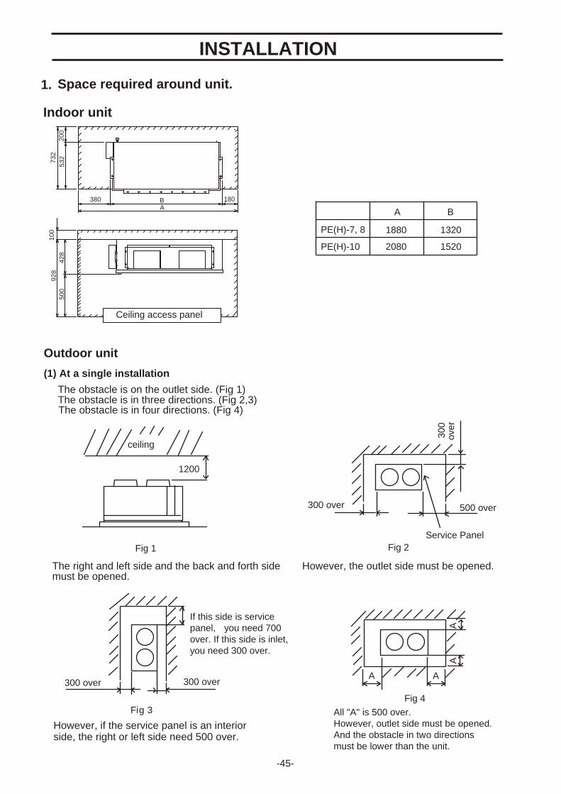
-45-
Space required around unit.
Indoor unit
1.
Ceiling access panel
200
732
380 BA
180
100
928
428
500
532
1880 1320
A B
2080 1520
PE(H)-7, 8
PE(H)-10
Outdoor unit
(1) At a single installation
The obstacle is on the outlet side. (Fig 1)The obstacle is in three directions. (Fig 2,3)
The right and left side and the back and forth sidemust be opened.
However, the outlet side must be opened.
However, if the service panel is an interiorside, the right or left side need 500 over.
The obstacle is in four directions. (Fig 4)
Fig 2Service Panel
500 over300 over
300
over
Fig 3
If this side is servicepanel, you need 700over. If this side is inlet,you need 300 over.
300 over 300 over
Fig 4
All "A" is 500 over.However, outlet side must be opened.And the obstacle in two directionsmust be lower than the unit.
A A
AA
Fig 1
ceiling
1200
INSTALLATION

-46-
(2) Relation of unit when many set up unit. (Fig 5,6,7)
300
over
Fig 6
Fig 5
All "A" is 500 over.
Fig 7 All "A" is 500 over in any case.
*B If this side isservice panel,you need 700 over.If this side is inlet,you need 300 over.
over500 over500
300 over
300
over
500
over
300 over AAAA 300 overB
A A A A A
Service-panel

Outdoor unit
Please use the M10 hanging bolt in any case.Hanging bolt is local supply.Please use the method below or use the angleand the rectangular lumber, etc. and installthe hanging bolt
A B C
B pitch is 130
1118 1040 39
1318 1170 74
PE(H)-7,8
PE(H)-10
-47-
677084202205230
PEH-7PEH-8PEH-10PU-7PU-8PU-10
211214240
PUH-7PUH-8PUH-10
Inlet side
Outlet side
Main body of unit
Control box
Gas pipe
Liquid pipeDrain pipe Electric wire
Insert etc100-150kg
Hanging bolt M10
Reinforcement
A 0.5
B
34
C 39
20 388 0.5
260
20025
50
156
152
95
40
44
45910 (pitch=130)
1000 0.5 120 250 0.598
+ +
+ +
(PITCH=130)
(PITCH=130)
Weight of unut(kg)
Indoor unit
Preparation before installing2.
28
18
120
235
175
100
2570025
540160122.5
108
980
875
25140025
700350
1372
4131000200CABLE ENTRY 25X40
REFRIGERANT PIPE PU(H)-7,8: 25.4 PU(H)-10 : 28.6
REFRIGERANT PIPE15.88
SERVICING PANEL
HOLES 4-12x20
622

Indoor unit
Please carry the packed until parallelly to installed place.Please install the unit before construction of the ceiling -lined.
Outdoor unit
Fix unit tightly with bolts as shown below so that unit will be securely fixed in place.Use concrete or angle foundation of unit.At the time of bottom piping of refrigerant pipe, build a 100mm or higher foundationso that piping will go through bottom of unit.
-48-
U washer
100
over
30
100
over
30
Nut
Nut
Washer
M10 anchor bolt(local arrangement)
Concrete foundation
724
installation of the unit3.

-49-
Lifting method.
4.Duct construction.Provide canvas flexible ducting between unit when connect to the duct-work.
The duct unit must use a nonflammable material.
Provide sufficient insulation for prevent dewdrop.
When the unit is to be lifted and moved, attach ropes to the suspension plates(3 p.c.s)
The angles at which the ropes suspend the unit should be at least 60 at the compressor endand at least 45 at the condenser end. Care should be taken to avoid contact with the main unit while carrying.
Hook(as directly aligned over the center ofgravity as possible.)
Condenser End
Compressor End
provided on the top of the unit.When the unit is lifted, it 's center of gravity tends to shift the unit one side and so balance, such as that in the figure below, should be attained.
Duct
Canvas Duct Canvas Duct
Outlet Inlet
Drain-pan
Duct
Air filter (field supply)
Duct-work length 850mm or more
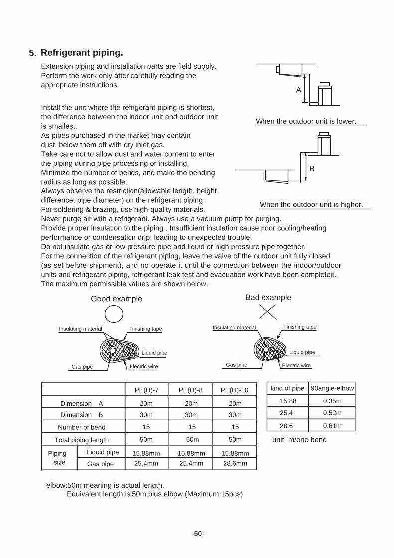
Extension piping and installation parts are field supply.
elbow:50m meaning is actual length. Equivalent length is 50m plus elbow.(Maximum 15pcs)
unit m/one bend
Perform the work only after carefully reading theappropriate instructions.
Install the unit where the refrigerant piping is shortest,the difference between the indoor unit and outdoor unitis smallest.As pipes purchased in the market may containdust, below them off with dry inlet gas.Take care not to allow dust and water content to enterthe piping during pipe processing or installing.Minimize the number of bends, and make the bendingradius as long as possible.Always observe the restriction(allowable length, heightdifference, pipe diameter) on the refrigerant piping.For soldering & brazing, use high-quality materials.Never purge air with a refrigerant. Always use a vacuum pump for purging.Provide proper insulation to the piping . Insufficient insulation cause poor cooling/heatingperformance or condensation drip, leading to unexpected trouble.Do not insulate gas or low pressure pipe and liquid or high pressure pipe together.For the connection of the refrigerant piping, leave the valve of the outdoor unit fully closed(as set before shipment), and no operate it until the connection between the indoor/outdoorunits and refrigerant piping, refrigerant leak test and evacuation work have been completed.The maximum permissible values are shown below.
When the outdoor unit is lower.
When the outdoor unit is higher.
PE(H)-10PE(H)-7 PE(H)-8
Dimension A 20m 20m 20m
30m30m30m
50m 50m 50m
15 15 15
Dimension B
Number of bend
Total piping length
Piping Liquid pipe 15.88mm 15.88mm 15.88mmsize Gas pipe 25.4mm 25.4mm 28.6mm
-50-
Finishing tape
Gas pipe
Insulating material
Liquid pipe
Good example
Electric wireElectric wire
Finishing tape
Gas pipe
Insulating material
Liquid pipe
Bad example
90angle-elbowkind of pipe
15.88 0.35m
0.52m25.4
28.6 0.61m
Refrigerant piping.5.
A
B

Airtight testAirtight test should be made by pressurizing nitrogen gas to 3Mpa.For the test method, refer to the following figure.(Make a test with the valve closed. Be also sure to pressurize both liquid and gas pipe.)The test result can be judged good if the pressure has not been reduced after leavingfor about one day after completion of nitrogen pressurization.
Evacuation should be made from the service port provided on the outdoor unit's valve tothe vacuum pump commonly used for both liquid pipe and gas pipe.(Make evacuation from both liquid pipe and gas pipe with valve closed.)Remember :Never carry out air purge by refrigerant.
Additional refrigerant chargeThe mount of refrigerant charged in this unit is a appropriate for 5-meter long refrigerant pipes.Refer to the table below and add the corresponding amount of refrigerant if the pipes areextended.
Vacuum pump
a
a
b
b
c
c
d
d
e
e
f
f
g
g
h
h
i
i
j
j
-51-
a.b.c.
d.e.
f.g.
h.i.j.
Nitrogen gasTo indoor unit
System analyzer
Low knobHigh knob
ValveLiquid gas
Gas pipeOutdoor unitService port
a.b.c.
d.e.
f.g.
h.i.j.
To indoor unitSystem analyzer
Low knobHigh knob
ValveLiquid gas
Gas pipeOutdoor unitService port
Refrigerant piping length
chargemount
PEH-7PE-10PE-8PE-7
PEH-8PEH-10 0
0
R-22(kg)
unit 5m 10m 15m 20m 25m 30m 35m 40m 45m 50m0.8 1.6 2.4 3.2 4.0 4.8 5.6 6.4 7.2
5.6 6.4 7.25.6 6.4 7.25.6 6.4 7.2
0 0.8 1.6 2.4 3.2 4.0 4.80 0.8 1.6 2.4 3.2 4.0 4.80 0.8 1.6 2.4 3.2 4.0 4.8
0.9 1.7 2.6 3.4 4.3 5.1 6.0 6.8 7.70 0.9 1.8 2.6 3.5 4.4 5.3 6.1 7.0 7.9

Incline the drain piping to the outside (drain side) as shown in the figure below.The outlet of the indoor unit drain pipe is 25mmBSP (male) thread.After completion of piping, confirm that drainage is good and that there are no leaks.
Indoor unit drain piping
Install thermal insulationto prevent dew
The drain piping should have a drain trap.
-52-
B
AC
The drain pipeshould extend below this level.
Drain pipingSlope 20mm/m
Open drainDrain trap
A 70mmB 2xC 70mmC 35mm
Drain pan
>=>=>=
>=
Drain piping6.

Construct the earth connection.All electrical work must be carried out by a suitable qualified electrical trades-person and inaccordance with local supply authority requirements and associated regulators.The outdoor unit is to be wired directly from an electrical distribution board either by a circuitbreaker (preferred) or HRC fuse.
Fix power source wiring to control box by using buffer bushing for tensible force (PGconnection or the like). Connect control wiring to control terminal block through the knockouthole of control box using ordinary bushing.
Arrangement such as terminal block in control box
Control module of Indoor unit Control module of Outdoor unit
-53-
Electric wiring7.
Terminal block for connection wiresto Outdoor unit and remote controller PE(H)-7 only
Terminal block for power supplywires Terminal block for
power supply wires
PEH only
Band for wires
Bush and band for the connection wiresto Outdoor unit and remote controller
Bush for the thermistor
Terminal blockfor connection wiresto Indoor unit
Screw for earth connection
PEH only
PEH only
Bush and band for the power supply

-54-
Method for connecting electric wirePlease do the wiring after consulting the electric power company of jurisdiction beforehandin the instruction.
(1) The entire wiring diagram of unit
a. Power supplyb. Main switch/fuse (field supply)c. Power supply wiring for outdoor unitd. Power supply wiring for indoor unite. Outdoor unitf. Indoor unitg. Connection wiring for indoor/outdoor
units (polarity)h Remote controller (field supply)i. Connection wiring for indoor/outdoor
units (no polarity)j Grounding
(2) Power supply construction and electric wiring connection of the indoor and outdoor unit
A. Indoor unitB. Power cable wiringC. Control cable wiring
(Fixing wire---Do not remove)D. Outdoor unitE. BreakerF. FuseG. Power cable terminal bedH. Control cable terminal bed
(3) Wiring example(For metal piping)
* The grounding wire must be of the same diameter as the power cable wires Table above is an example. The selection of other capacities should be determined in accordance with the relevant standards.
Note: All electrical wiring must be comply with local electrical authority regulations.
a a
bb
c d
g
ife
jj h
F
B
E H
H
G
A (3 phase)
(3 phase)
Single phase(PE(H)-7)
DL1 L2 L3 N
L1 L2 L3 N 13 14 15
13 14 15
C
PEH only
Power cable Breakercapacity
Over currentprotection switch
Earth cable Control cable
PE(H)-7/8PU(H)-7/8PE(H)-10PU(H)-10
1.6mm
1.6mm8mm
14mm
2
2
2
2
22
15A
15A50A
60A
15A
15A50A
60A
3.5mm over
3.5mm over5.5mm over
5.5mm over
Cable or wireof 2.0mm(24VDC)

-55-
(4) Selecting earth leakage breaker (NV)
To select NF or NV instead of a combination of Class B fuse switch use the following.In the case of Class B fuse rated 15A
Fuse (class B) 15A 50A 60A
Earth leakage breaker NV-30CA NV-50CF NV-60CF(with over-load protection) 15A 50A 60A
30mA 0.1s or less 100mA 0.1s or less 100mA 0.1s or lessNV is a product of MITSUBISHI.Table above is an example. The selection of other capacities should be determined in accordance with the relevant standards.
Note: All electrical wiring must be comply with local electrical authority regulations.
8. Before starting the Trial run.
Check items(1) Check to see whether there are refrigerant leakage, and slack power or transmission cable.(2) Conform that 500V megohmmeter shows 1.0M ohm or more between power supply terminal and ground.(3) Do not operate in the case of 1.0M ohm or less.
Note: Never carry out megger-ohm check over terminal control board. Otherwise the control board would be broken.(4) Check to see whether both gas and liquid valves are fully opened.
Note: Be sure to tighten caps.(5) Turn universal power supply at least 6 hours before getting test run in order to current to crank heater.
If current -carrying hours are too short, it may result in a malfunction of compressor.(6) Confirm operation of high-pressure switch.
If the two lead wires of the outdoor unit fan motor are disconnected from the connector and cooling is performed, the high-pressure switch should operate and stop the unit after 5 to 10 minutes.
(7) Confirm that the fans of the indoor and outdoor unit rotate in the correct direction.Change the power supply phase connections if it is rotating in the reverse direction.
Perform trial operation after completion of the above items.

-56-
1.Check points for operation.Check the following points before you operate your air conditioner.
(1)Check that there is nothing blocking the flow of air from the air outlet into the air inlet.
Indoor unit
Outdoor unit
(2)Make sure the air conditioner is properly grounded by checking the ground terminal.
INSTRUCTION FOR USE
Obstacle blocking air inlet.
Ground
Obstacle blocking air inlet
Ceiling
Inlet grille
Ceiling
Outlet grille
Obstacle blocking air inlet

-57-
2.Caution for use.Keep the following points in mind to safeguard against failures and breakdowns.
(1) This air conditioner does not restart within 3min.after shut down. (These models have a crankcase heater in the compressor. If the air conditioner is shut down for a short time, please do not turn the power switch to OFF, but turn the operation switch to OFF.)
(2) If the air conditioner is shut down by a power failure, set the operation switch to OFF. When the power is restored, normal air conditioner operation can be resumed.
(3) Do not stick rods or other objects through the air outlet during operation since this may result in equipment damage or personal injury.
3.Maintenance. For superior performance and lasting durability, please do not forget to conduct
proper and regular maintenance .
3.1 Cleaning the Air Filter (Field supply) Clean the air filter about once a week with a neutral cleanser and leave it to dry in a shady location.
Clean more regularly if the air filter gets very dirty. If the filter gets blocked, air will not be sucked in properly, and the cooling effect will deteriorate. Failure to clean the air filter may result in equipment breakdown or malfunctions.
3.2 Cleaning panelsClean dirt off front panel as follows.
Use a household neutral cleanser such as for dishes or vegetables. Moisten a soft cloth with the cleanser, then wipe lightly. Next,wipe three or four times with another soft cloth moisten with water. Finally, wipe off all the remaining
cleanser with a soft cloth.Moisten a soft cloth with the alcohol, then wipe off lightly.
Isopropyl alcohol is sold at stores as reagents in small quantities.
Note: Alcohol is highly combustible. Take extreme care when handling. Also, do not use paint or adhesive thinner.
1.Do not wash the product with water. If washed with water, electrical shock may be caused. 2.Ahead of the maintenance. For safety, turn the power source off before service work.
Fingermarks NeutralCleanser
Grease
Shutdown Operation
Adhesive Isopropylalcohol
Paste
3 Minutes
Warning

-58-
3.3 Cleaning the Outdoor Unit Heat ExchangerIf you use your air conditioner for prolonged periods,
the outdoor heat exchanger will become dirty, impairing its function and reducing air conditioners performance. Consult your equipment supplier or air conditioning contractor on how to clean the heat exchanger.
4.When beginning to use air conditioner again.Please turn on the power supply after confirming an following check is done andabnormality is not found.
(1) It is confirmed that air inlet and outlet are not blocked.
(2) It is confirmed that the earth connection line does not come off.
The earth connection line is occasionally installed in the outdoor unit.
(3) It is confirmed that there are neither lifting , blocking , nor bending about the drain-hose.
Keep the power switch ON for more than 6hours before starting operation,to operate the crankcase heater to drive refrigerant out of oil.
Do not turn the power supply OFF during seasons of heavy use.Doing so can result in failure .
5.When the air conditioner is not to be used for a long time.(1) If the air conditioner is not to be used for a long time due to a seasonal change etc.,run it for 4-5hours
with the air blowing until the inside is completely dry.
Failing to do so can result the growth of unhygienic, unhealthy mold in scattered areas throughout
the room.
(2) When it is not to be used for an extended time, keep the < power supply >turned OFF.
If the power supply is kept on, several watts or several tens of watts will be wasted.
Also, the accumulation of dust, etc., can result in fire.
Heat exchanger

-59-
6. Troubleshooting.
Before you ask for repair service, check the following point:
State of Machine Cause Troubleshootin gBoth fan and compressor Power failure. Wait for power supply recovery.do not run. Blown fuse of power source switch. Contact your installing contractor.
Excessively low power source voltage. Ask your electric power company.
Fan runs but compressordoes not run.
The set temperature of thermostat isexcessively high for cooling.excessively high for heating. (PEH only)
For temperature control,decrease the set temperature atcooling.increase the set temperature atheating. (PEH only)
The room temperature isexcessively high for cooling.excessively high for heating. (PEH only)
Can not be operated as it is out oftemperature control range.
Fan runs but stopsimmediately .
Air outlet and inlet are blocked. Remove blocking matter.
The filter installed in the field isclogged with dust.
Clean the filter and establishcleaning program.
Windows and doors are being opened. Close them.Runs but it does not Air outlet and inlet are blocked. Remove blocking matter.Cool or heat enou gh. The set temperature of thermostat is
excessively high for cooling.excessively high for heating. (PEH only)
For temperature control,decrease the set temperature atcooling.increase the set temperature atheating. (PEH only)
Insufficient refrigerant charge. Contact with your installingcontractor.
Fogged white steam isdischar ged fromthe indoor unit.
When the indoor temperature and humidity arehigh, such a phenomenon is occasionally hadat the beginning of system operation.
Please use as it is.
Water or steam isdischar ged fromthe outdoor unit.
At cooling, water which places to coolingpiping and piping connection part drops .When heating, water which places to the heatexchanger drops. (PEH only)
Please use as it is.
On heatin g , does not heatenough. (PEH only)
Frost adheres to the outdoor coil when thetemperature on the outside is low and humidityis high.This frost is melted.
Please wait about ten minutes.
Note.
1. PE-7,8,10MYC , PEH-7,8,10MYA (MECHANICAL CONTROL)
When the fault of outdoor unit is occurred, the fan(MF1) of indoor unit continues to work.
But the unit doesn't work correctly (not cooling and heating ).
Then, turn off the power supply and check outdoor unit.
2. PE-7,8,10MYC-K , PEH-7,8,10MYA-K (K CONTROL)
When the fault of outdoor unit is occurred, the fan(MF1) of indoor unit continues to work only in cooling mode.
In addition, the error code (“P8”) of outdoor unit will be appeared on the remote controller.
Then, turn off the power supply and check outdoor unit.

Due to continuous product development, these guidelines are subject to change.
-60-
Air to air reverse cycle split air conditioning system.
The systems shall operate at out door ambient temperatures as high as .
The system shall have a total cooling capacity of kW or greater with an indoor air quantity of L/sat DB and WB entering indoor coil temperature with a temperature entering the outdoor coil.
The system shall have a sensible heat capacity of kW or greater with a room DB temperature of .
The total heating capacity (without electric element heaters) shall be 45kW or greater at DB, WB outdoor air conditions, with of indoor air entering indoor coil at DB.
The compressors shall be a welded high efficiency hermetic type with internal vibration isolation and beequipped with a crankcase heater.
Coils shall be of non-ferrous construction with mechanically bonded aluminum plate fins Outdoor coilsshall be made, of 9.52mm OD, 0.35mm thick formless copper tubes mechanically bonded to 0.12mmthick aluminum plate fins.
Face area of the coil shall not be less than m2 The coil shall be factory pressure and leak tested at3,233 kPa pressure. The indoor coil face area shall be not less than m2 .
Multi-wing propeller type fans shall be fitted at the condenser and shall be dynamically balanced, toensure smooth airflow and shall discharge vertically and be direct driven by a weatherproof threephase squirrel cage kW induction motor.
The system shall be factory wired and all electrical wiring must comply with the Local wiring code (Controlsand control wiring shall be supplied by the contractor). Compressors and fan motors shall have both internaland current sensitive overload devices.
An automatic defrost control shall be included to accomplish defrosting (only if required) every minutesfor a period of minutes.
High pressure switch (pre-set) shall be factory installed.
The enclosure is weatherproof casing constructed of phosphatized, zinc coated steel with powder coating.
The unit shall be provided with hoisting plates for rigging and hoisting the unit. The hoisting plates shall
be located in the pillars. (OUTDOOR UNIT)
(OUTDOOR UNIT)
The unit shall have a drain connection provided (25mm BSP:male thread).
The enclosure shall have openings provided for power connections.
Access for both service and installation shall be provided to compressors, control wiring, and fans.
Side panels and top panels shall be removable for easy service access.
The unit maximum dimensions shall be : height: mm, width: mm and depth: mm (INDOOR UNIT )
: height: mm, width: mm and depth: mm (OUTDOOR UNIT)
SPECIFICATION GUIDELINES

This product is designed and intended for use in the residential,
commercial and light-industrial environment.
The Equipment Safety Low(GSG)
accepted by RW-TUV.
Low Voltage Directive 73/23/EEC
Electromagnetic Compatibility Directive 89/
336/EEC
Machinery Directive 89/392/EEC
Please be sure to put the contact address/telephone number on the
operation manual before handing it to the customer.
HEAD OFFICE MISTUBISHI DENNKI BLDG MARUNOUCHI TOKYO 100-0005 TELEX J24532 CABLE MELCO TOKYO
The product at hand is
based on the following
EU regulations:
MEN10-412A Specifications subject to change without notice.New publication Aug. 1998.