pecon condense catalogue 2013
DESCRIPTION
Power Electronics & Control PECON 2013 catalgoueTRANSCRIPT

yearsA N N I V E R S A R Y
1 9 7 3 - 2 0 1 3
40
ISO 9001:2008 Certified
Power Electronics & Control
Condensed Catalogue
Jan 2013
MA - 116Power Electronics & Control
1 2 3 4
5 6 7 8
9 10 11 12
13 14 15 16
Reset F/OReset Test Power
AcceptAcceptReset F/O
Reset

Power Electronics & Control, better known by it’s brand name PECON, has been associated withElectrical & Power Industry, since 1973. Starting a small way, it has covered a long way becoming oneof the most trusted name in transformer protection and temperature surveillance system. PECON is aclose knit company with well qualified & trained manpower.
PECON is pioneer in electronic type OTI / WTIs, for both Oil cooled and Dry type transformers. With over 50,000 installations in the field, PECON is surely the leader in India in this field. OEM list includes almost all majors in transformer industries in INDIA. Our products are also exported to European & U.S. markets.
PECON is committed to technical excellence and complete customer satisfaction.
Associate Company
Via L. da Vinci 54/56 - 20094Corsico (MI) - ITALY
Electronic type temperature survillience systems and
ventillations fans for transformers.
882/2, G.I.D.C Estate,Makarpura, Vadodara : 390 010
Instrumentation Panels,Turnkey instrumentation jobs,
PLC/DAS based Control Panels.
Group Company
Positronics (Pvt) Ltd

INDEX
7 Channel WTS with dual 4-20mA
7 Channel WTS with 4-20mA & RS-485
Single channel WTS with 4-20mA
Single channel WTS with RS-485
1
2
3
4
5
4 Channel WTS with 4-20mA
4 Channel WTS with RS-485
4 Channel WTS with 4-20mA inputs
6 Channel WTS with 4-20mA
6 Channel WTS with RS-485
6 Channel WTS with dual 4-20mA
6 Channel WTS with 4-20mA & RS-485
6 Channel WTS with Profibus-DP
4 Channel WTS with 4-20mA
4 Channel WTS with RS-485
4 Channel WTS with dual 4-20mA
4 Channel WTS with 4-20mA & RS-485
TR-7543
TR-7543-C
TR-7577-Rx
TR-7577-CX
TR-7544
TR-7544-C
TR-7544-SP
TR-7576
TR-7576-C
TR-7576-Rx
TR-7576-Cx
TR-7576-CP
TR-7570
TR-7570-C
TR-7570-RX
TR-7570-CX
FO
R D
RY
TY
PE
/ C
AS
T R
ES
IN T
RA
NS
FO
RM
ER
S
i

ii
TR-8080 spl+
SPT-04
4 Channel split type WTS
with 4-20mA & RS-485
TR-7560 3 Channel WTS with 4-20mA & 0-1mA
TR-7541-M
TR-7541-C
6
7
8
9
10
11
TR-7578
TR-7578-C
8 Channel WTS with 4-20mA
8 Channel WTS with 4-20mA & RS-485
Single channel WTI with 4-20mA
Single channel WTI with RS-485
S-02 Sensor Pt-100
JB-01 Junction Box (for 4 S-02 sensors)FO
R D
RY
TY
PE
/ C
AS
T R
ES
IN T
RA
NS
FO
RM
ER
S
TR-8080-FO+
FOXTR-02+
SFO-01
3 Channel WTSFor HT & EHT Transformer Windings
With Fiber Optics Temperature Transmitter,Fiber Optic Sensors &
4-20mA & RS-485 outputs.
TPR-05 Thermistor Relay 12
iii
14
15
13
16
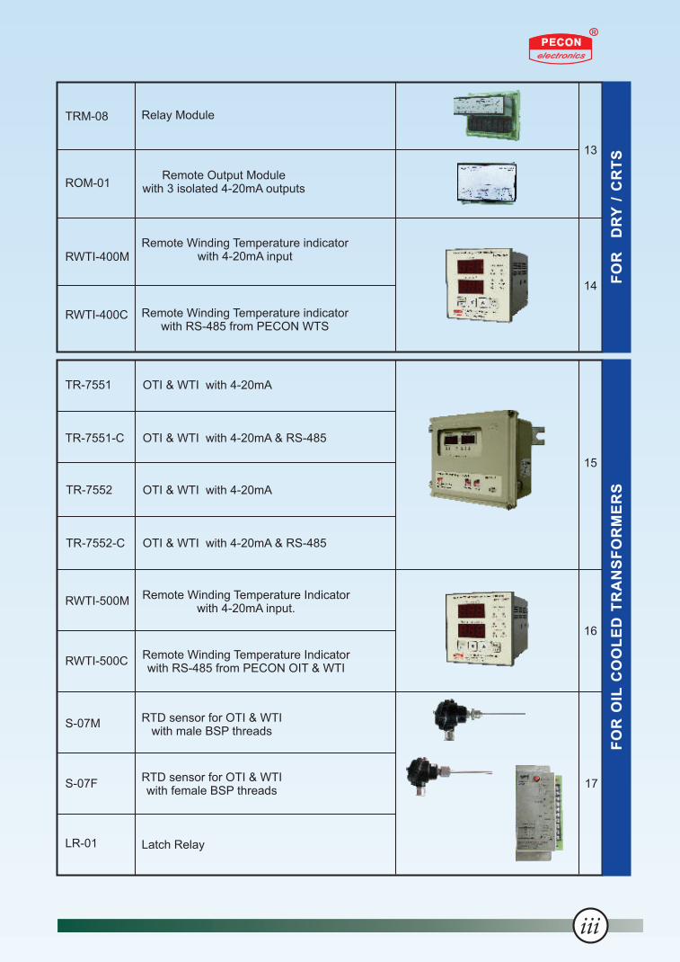
Remote Winding Temperature Indicatorwith 4-20mA input.
Remote Winding Temperature Indicatorwith RS-485 from PECON OIT & WTI
RWTI-500M
RWTI-500C
S-07M
S-07F
LR-01
RTD sensor for OTI & WTIwith female BSP threads
RTD sensor for OTI & WTIwith male BSP threads
Latch Relay
17
RWTI-400M
RWTI-400C
Remote Winding Temperature indicatorwith 4-20mA input
Remote Winding Temperature indicatorwith RS-485 from PECON WTS
OTI & WTI with 4-20mA
OTI & WTI with 4-20mA & RS-485
OTI & WTI with 4-20mA & RS-485
OTI & WTI with 4-20mA
TR-7551
TR-7551-C
TR-7552
TR-7552-C
FO
R O
IL C
OO
LE
D T
RA
NS
FO
RM
ER
SF
OR
D
RY
/ C
RT
S
TRM-08 Relay Module
ROM-01Remote Output Module
with 3 isolated 4-20mA outputs

4 Channel WTS for CRT
4 Channel WTS for CRT
OTI & WTI for oil cooled transformers
Transformer Cooling Fan
Application note & FAQs
22
23
24
NT-133 IT
TTG-240
NT-935
T-154
TE
CS
YS
TE
M P
RO
DU
CT
S
MA-116
MA-112
MA-108
MA-106
16 Channel Window Annunciator
12 Channel Window Annunciator
8 Channel Window Annunciator
6 Channel Window Annunciator
Dimension & Mounting DetailsFigure 2 to 6
18
2090
96
96
10 125
Front View Side View
MA - 116Power Electronics & Control
1 2 3 4
5 6 7 8
9 10 11 12
13 14 15 16
Reset F/OReset Test Power
AcceptAcceptReset F/O
Reset
UT-101
UT-102
Temperature / Process Scanner
Temperature Scanner
CO
NT
RO
L R
OO
MD
IME
NS
ION
NO
TE
S
19
iv

Transformer Protection Relay
TR-7570
Note : For dimension & mounting details, please refer Figure - 2 on Page 20.
D
RY
/
CA
ST
R
ES
IN
OIL
C
OO
LE
DC
ON
TR
OL
R
OO
MD
IME
NS
ION
TE
CS
YS
TE
MA
PP
LIC
AT
ION
N
OT
E
TR-7570
Salient features :
Four channel temperature scanner.
Temperature indication range : – 50 to 300 °C.
Four relay outputs for Fault, Fan, High (Alarm) &Very High (Trip).
Independent set of setpoints for 4th Channel.
4-20mA / RS-485 output for remote temperature indication / DAS / SCADA application (view options).
Aux. Supply : 85-270 VAC/DC (Optionally 20-50 VAC/DC).
Output Signals TR-7570 TR-7570-C TR-7570-Rx TR-7570-Cx
Remote output – 1 (4-20mA)
YES NO YES YES
Remote output – 2 (4-20mA)
NO NO YES NO
RS-485 (MODBUS protocol)
NO YES NO YES
Fault FanHigh Very HighRTD 1 RTD 2 RTD 3 RTD 4 Remoteo/p
+
-
NC
1513 14 1716 1819 20212223241 2 3 4 5 6 7 8 9 10 11 12 2526 2829 30
Aux Supply85 - 270 VAC/DC
Fault FanHigh Very HighRTD 1 RTD 2 RTD 3 RTD 4
NC
Aux Supply85 - 270 VAC/DCBA
RS-485
13 1415 16171819 20212223241 2 3 4 5 6 7 8 9 10 11 12 2829 302526
TR-7570
TR-7570-C
Inputs
Inputs
Input
Input
Outputs
Outputs
BARS-485
Remoteo/p
-
+
Fault
Fault
Fan
Fan
High
High
Very High
Very High
RTD 1
RTD 1
RTD 2
RTD 2
RTD 3
RTD 3
RTD 4
RTD 4
NC
3940 414213 1415 16171819 20212223241 2 3 4 5 6 7 8 9 10 11 12 2829 30
Aux Supply85 - 270 VAC/DC
Aux Supply85 - 270 VAC/DC
TR-7570-Cx
Inputs
Inputs Input
InputOutputs
Outputs
Remote o/p
1 2
+ +
- -TR-7570-Rx
NC
39 4140 4213 1415 16171819 20212223241 2 3 4 5 6 7 8 9 10 11 12 2829 30
Terminal details :
1
Options :

TR-7576
Salient features :
Six channel temperature scanner.
Temperature indication range : – 20 to 250 °C.
Fan exerciser function.
Test Function to simulate operation of WTS.
Independent set of setpoints for 6th Channel. 4 Relay o/ps for Fault, Fan, High (Alarm) & Very High (Trip).
4-20mA / RS-485 / Profibus output for remote temperature indication / DAS / SCADA application (refer options).
Aux. Supply : 85-270 VAC/DC (Optionally 20-50 VAC/DC).
Transformer Protection RelayTR-7576
Note : For dimension & mounting details, please refer Figure - 2 on Page 20.
Output Signals TR-7576 TR-7576-C TR-7576-Rx TR-7576-Cx TR-7576-CP
Remote output – 1 (4-20mA)
YES NO YES YES NO
Remote output – 2 (4-20mA)
NO NO YES NO NO
RS-485 (MODBUS protocol)
NO YES NO YES NO
Profibus- DP protocol NO NO NO NO YES
D
RY
/
CA
ST
R
ES
IN
OIL
C
OO
LE
DC
ON
TR
OL
R
OO
MD
IME
NS
ION
TE
CS
YS
TE
MA
PP
LIC
AT
ION
N
OT
E
ProfibusDP
GBA
414243
Aux. Supply85-270
VAC-DC
1 2 3 4 5 6 7 8 9 10 11 121314151617183940 2321 2422 252627282930 31
Remoteo/pRTD 1 HighFault V.High FanRTD 2 RTD 3 RTD 4 RTD 5 RTD 6
RS-485BA
4142
++
--
414243
RS-485GBA
1 2 3 4 5 6 7 8 9 10 11 121314151617181920 21222324252627282930 31
+
Aux. Supply85-270
VAC-DC-
Fault High V.High FanRemote
o/pRTD 1 RTD 2 RTD 3 RTD 4 RTD 5 RTD 6
1
1
1
2
2
2
3
3
3
4
4
4
5
5
5
6
6
6
7
7
7
8
8
8
9
9
9
10
10
10
11
11
11
12
12
12
13
13
13
14
14
14
15
15
15
16
16
16
17
17
17
18
18
18
21
21
22
22
23
2321
23
24
2422
24
25
25
25
26
26
26
27
27
27
28
28
28
29
29
29
30
30
30
31
31
31
Aux. Supply85-270
VAC-DC
Aux. Supply85-270
VAC-DC
Aux. Supply85-270
VAC-DC
Fault
Fault
High
HighFault
High
V.High
V.High
V.High
Fan
Fan
Fan
RTD 1
RTD 1
RTD 1
RTD 2
RTD 2
RTD 2
RTD 3
RTD 3
RTD 3
RTD 4
RTD 4
RTD 4
RTD 5
RTD 5
RTD 5
RTD 6
RTD 6
RTD 6
TR-7576
TR-7576-C
TR-7576-Rx
TR-7576-CP
TR-7576-Cx
Inputs
Inputs
Inputs
Inputs
Inputs
Outputs
Outputs
Outputs
Outputs
Outputs
Input
Input
Input
Input
Input
Remote o/p
1 2
+ +
- -
39 4140 42
Terminal details :
2
Options :

Note : For dimension & mounting details, please refer Figure - 2 on Page 20.
Salient features :
Seven channel temperature scanner.
Temperature indication range : – 20 to 250 °C.
Fan exerciser function.
Test Function to simulate operation of WTS.
Three relay outputs for High (Alarm), Very High (Trip) and Fault / Fan (configure either as Fan or Fault relay at site).
Independent set of setpoints for 7th Channel.
4-20 mA / RS-485 output for remote temperature indication and / or DAS / SCADA application (refer options).
Aux. Supply: 85-270 VAC/DC (Optionally 20-50 VAC/DC).
D
RY
/
CA
ST
R
ES
IN
OIL
C
OO
LE
DC
ON
TR
OL
R
OO
MD
IME
NS
ION
TE
CS
YS
TE
MA
PP
LIC
AT
ION
N
OT
E
TR-7577-Rx
Output Signals TR-7577-Rx TR-7577-Cx
Remote output – 1 (4-20mA)
YES YES
Remote output – 2 (4-20mA)
YES NO
RS-485 (MODBUS protocol)
NO YES
Terminal details :
Remote o/p Aux. Supply85-270
VAC-DC
RTD 1 High V.High FanFLT/
1 2 3 4 5 6 7 8 9 10 11 1213141516 1917 2018 2139 4140 42 23242526272830 31
RTD 2 RTD 3 RTD 4 RTD 5 RTD 6 RTD 71 2
+ +
- -
Aux. Supply85-270
VAC-DC
RTD 1 High V.High FanFLT/RTD 2 RTD 3 RTD 4 RTD 5 RTD 6 RTD 7
BA
RS-485
Remoteo/p
1 2 3 4 5 6 7 8 9 10 11 1213141516 1917 2018 21 23242526272830 3139 4140 42
+
-
TR-7577-Rx
TR-7577-Cx
Inputs
Inputs
Outputs
Outputs
Input
Input
TR-7577-Rx / TR-7577-Cx
Transformer Protection Relay
3
Options :

Note : For dimension & mounting details, please refer Figure - 3 on Page 20.
D
RY
/
CA
ST
R
ES
IN
OIL
C
OO
LE
DC
ON
TR
OL
R
OO
MD
IME
NS
ION
TE
CS
YS
TE
MA
PP
LIC
AT
ION
N
OT
E
Salient features :
Single channel temperature indicator.
Temperature indication range : -20 to 250 °C.
Test function to simulate operation of WTI.
4 Relay outputs for Fault, Fan, Alarm & Trip.
Fan relay is rated for 10A @ 230VAC.
4-20mA / RS-485 output for remote temperature indication and / or DAS / SCADA application (refer options).
Enclosure : Noryl (Fire retardant material).
Aux. Supply : 85-270 VAC/DC (Optionally 20-50 VAC/DC).
Transformer Protection Relay
TR-7543
Terminal details :
RTD
RTD
5
5
6
6
Fault
Fault
7
7
8
8
9
9
Fan
Fan
10
10
11
11
12
12
Alarm
Alarm
13
13
14
14
15
15
16
16
Trip
Trip
17
17
18
18
19
19
Aux. Supply85-270
VAC-DC
Aux. Supply85-270
VAC-DC
N
N
L
L
E
E
1
1
2
2
3
3
Remoteo/p
2829
+
-
B GA
RS-485
3031 32
TR-7543
TR-7543-C
Outputs
Outputs
Input
Input
Input
Input
Input
Input
Output
Output
Output Signals TR-7543 TR-7543-C
Remote output (4-20mA)
YES NO
RS-485 (MODBUS protocol)
NO YES
TR-7543
4
Options :

Note : For dimension & mounting details, please refer Figure - 3 on Page 20.
TR-7544
Salient features :
Four channel temperature scanner.
Temperature indication range : – 20 to 250 °C.
Test function to simulate operation of WTS.
Four relay outputs for Fault, Fan, Alarm & Trip.
Fan relay is rated for 10A @ 230VAC.
4-20mA / RS-485 output for remote temperature indication and / or DAS / SCADA application (refer options).
Enclosure : Noryl (Fire retardant material).
Aux. Supply : 85-270 VAC/DC (Optionally 20-50 VAC/DC).
TR-7544
Transformer Protection Relay
D
RY
/
CA
ST
R
ES
IN
OIL
C
OO
LE
DC
ON
TR
OL
R
OO
MD
IME
NS
ION
TE
CS
YS
TE
MA
PP
LIC
AT
ION
N
OT
E
5
Signals TR-7544 TR-7544-C TR-7544-SP
Input signal RTD, Pt-100 RTD, Pt-100 4-20mA
Remote output signal (4-20mA)
YES NO YES
RS-485 (MODBUS protocol)
NO YES NO
RTD 1
4 5 6
Fault
7 8 9
Fan
10 11 12
Alarm
131415
Trip
16 171819 20 2122 2324 25 26 27
RTD 2 RTD 3 RTD 4Aux. Supply85-270
VAC-DC
NLE
1 2 3
Remoteo/p
2829
+
-TR-7544
OutputsInputInput Inputs Output
B GA
RS-485
303132
RTD 1
4 5 6
Fault
7 8 9
Fan
10 11 12
Alarm
131415
Trip
16 171819 20 2122 2324 25 26 27
RTD 2 RTD 3 RTD 4Aux. Supply85-270
VAC-DC
NLE
1 2 3
TR-7544-C
OutputsInputInput Inputs Output
4 5 6
Fault
7 8 9
Fan
1410 12
Alarm
131415
TripAux. Supply85-270
VAC-DC
NLE
1 2 3
TR-7544-SP
OutputsInputInput 4-20mA Inputs Output
Remoteo/p
2829
+
-
CH # 1 CH # 2 CH # 3 CH # 4
NC NC NC NC
16 19 22 2517 20 23 2618 21 24 27
+ + + +
Options :
Terminal details :

Note : For dimension & mounting details, please refer Figure - 2 on Page 20.
Transformer Protection Relay
TR-7541-M
TR-7541-M
Salient features :
Single channel temperature scanner.
Temperature indication range : – 50 to 300 °C.
Two relay outputs for Alarm & Trip.
4-20mA / RS-485 output for remote temperature indication and / or DAS / SCADA application (refer options).
Enclosure : Weatherproof Aluminum die cast (IP-65), with polycarbonate viewing window.
Aux. Supply : 85-270 VAC/DC (Optionally 20-50 VAC/DC).
Output Signals TR-7541-M TR-7541-C
Remote output (4-20mA)
YES YES
RS-485 (MODBUS protocol)
NO YES
D
RY
/
CA
ST
R
ES
IN
OIL
C
OO
LE
DC
ON
TR
OL
R
OO
MD
IME
NS
ION
TE
CS
YS
TE
MA
PP
LIC
AT
ION
N
OT
E
TR-7541-M
TR-7541-M
TripAlarm
86 971 2 3 4 5 414243
RTD
Output Outputs InputInput
Remoteo/p
+
-
NC
10 11 12
Aux Supply85 - 270 VAC/DC
414243
A B G
RS-485
Terminalsnot
provided
TR-7541-C
TripAlarm
86 971 2 3 4 5
RTD
Output Outputs InputInputInput Output
Remoteo/p
+
-
NC
10 1112
Aux Supply85 - 270 VAC/DC
Terminal details :
6
Options :

Note : For dimension & mounting details, please refer Figure - 1 on Page 9.
Transformer Protection Relay
TR-7578
TR-7578
D
RY
/
CA
ST
R
ES
IN
OIL
C
OO
LE
DC
ON
TR
OL
R
OO
MD
IME
NS
ION
TE
CS
YS
TE
MA
PP
LIC
AT
ION
N
OT
E
Salient features :
Eight channel temperature scanner.
Temperature indication range : – 20 to 250 °C.
Four relay outputs for Fault, Fan, Alarm & Trip.
4-20mA / RS-485 output for remote temperature indication / DAS / SCADA application (refer options).
Aux. Supply : 85-270 VAC/DC (Optionally 20-50 VAC/DC).
Output Signals TR-7578 TR-7578-C
Remote output (4-20mA)
YES YES
RS-485 (MODBUS protocol)
NO YES
RTD 1
RTD 1
RTD 2
RTD 2
RTD 3
RTD 3
RTD 4
RTD 4
RTD 5
RTD 5
RTD 6
RTD 6
RTD 7
RTD 7
RTD 8
RTD 8
1
1
4
4
7
7
10
10
13
13
16
16
19
19
22
22
2
2
5
5
8
8
11
11
14
14
17
17
20
20
23
23
3
3
6
6
9
9
12
12
15
15
18
18
21
21
24
24
B GA
RS-485
717273
Aux. Supply85-270
VAC-DC
NC
Remoteo/p
+
-
Fan FaultAlarm
2829 302526 31 3233 34353637 3839404142
Trip
Aux. Supply85-270
VAC-DC
NC
2829 30
Remoteo/p
2526
+
-
31 3233
Fan
343536
Fault
37 3839
Alarm
404142
Trip
TR-7578
TR-7578-C
Inputs
Inputs
Outputs
Outputs
Input
Input
Output
Output
7
Options :
Terminal details :

Note : For dimension & mounting details of TR-8080 spt, please refer Figure - 2 on Page 20. For dimension & mounting details of SPT-04, please refer Figure - 5 on Page 21.
Transformer Protection System (Spilt Type)TR-8080 spt + SPT-04
D
RY
/
CA
ST
R
ES
IN
OIL
C
OO
LE
DC
ON
TR
OL
R
OO
MD
IME
NS
ION
TE
CS
YS
TE
MA
PP
LIC
AT
ION
N
OT
E
Salient features :
Split type architecture, simplifies the wiring.
Ease in case of replacement of RTD / RTD Module or Main scanner unit.
Temperature indication range : – 50 to 300 °C.
Four relay outputs for Fault, Fan, Alarm & Trip.
SPT-04 is designed for four S-02 inputs. Models with more i/p channels are also available.
PECON proprietary “Data Bus” for communication between TR-8080 spt & SPT-04.
4-20mA / RS-485 output for remote temperature indication / DAS / SCADA application.
Enclosures :(A) TR-8080 spt : Weatherproof Aluminum die cast (IP-65).(B) SPT-04 : 35 mm. Din Rail mount, Base - Polyamide.
Aux. Supply : 85-270 VAC/DC (Optionally 20-50 VAC/DC).
Schematic Diagram :
Terminal details :
72 7374
Fault
757677
Fan
NCNC
78 7980
Alarm
81828384858687
Trip
RS-485
GBA
P+ P- D+ D-
61 626364 65 6667 6869 70 71
Remote o/p
+
-
Aux Supply85 - 270 VAC/DCTR-8080 spt
Data Bus Outputs
P+ P- D+ D-
61 626364
Data Bus
Input
RTD 1 RTD 2 RTD 3 RTD 4
1 2 3 4 5 6 7 8 9 10 11 12
SPT-04
Inputs
SPT-04
TR-8080 spt
0
Wh
ite
Red
Red
3
8

TR-7560
Transformer Protection Relay
Trip
240 110 N
Alarm
1715 18161 32 4 5 8 116 9 127 10 13
RTDCH-R
RTDCH-Y
RTDCH-B 4-20 mA 0-1 mA
Remote o/p
+ +
- -
1920 21
Aux Supply110 / 240 VAC
TR-7560
Outputs Inputs InputOutputs
Figure - 1
FRONT VIEW
260
235
33
031
5
135
EARTHINGCONNECTION MOUNTING
PLATE
CABLEENTRY
SIDE VIEW
235
3 Nos.M-6 THREADS
MOUNTING DETAILS
Note : All dimensions are in mm.
+ 5 0
+ 5
0
20
5Dimension & Mounting Details for TR-7560 & TR-7578 :
D
RY
/
CA
ST
R
ES
IN
OIL
C
OO
LE
DC
ON
TR
OL
R
OO
MD
IME
NS
ION
TE
CS
YS
TE
MA
PP
LIC
AT
ION
N
OT
E
Salient features :
Solid-state design.
Three channel temperature scanner.
Temperature indication range : 0.0 to 199.9 °C.
Two relay outputs – for Alarm & Trip.
4-20mA & 0-1mA outputs for remote temperature indication and / or DAS / SCADA application.
Aux. Supply : 240 / 110 VAC.( Optionally 85-270 VAC/DC & 20-50 VAC/DC ).
TR-7560
9
Terminal details :

Junction BoxJB-01
Sensor details :
Dimension & Mounting Details :
S-02
RTD Sensor
Red
White
Red
Re
d
Re
d
Wh
ite
Pt
- 1
00
RTD Sensor S-02
40 mm max.
Max. 4 mm
Pt-100 elementinside heat shrink sleeve
Extention leads teflon over teflon insulated silver plated copper wires 24/7/32 AWG terminated on Bootlace ferrules(Standard lead length is 1000 mm +25 mm)
Note :O1) RTD Sensor S-02 is suitable over -50 to +200 C temperature range
2) Sensor S-02 is Class B (IEC-60751)O permissible error C = ± [ 0.3 + (.005 x t) ]
O where t is the temperature in C.3) Longer lead lengths are available for specific needs.
These sensors are tested for :
1) DimensionsO O O2) Calibration at 50 C, 100 C & at 180 C
3) Dielectric Strength : 2KV rms for 1 min.
JB-01
D
RY
/
CA
ST
R
ES
IN
OIL
C
OO
LE
DC
ON
TR
OL
R
OO
MD
IME
NS
ION
TE
CS
YS
TE
MA
PP
LIC
AT
ION
N
OT
E
Salient features :
Suitable to all our WTI / WTS.
3 wire, Pt-100 type sensor ( IEC-60751, Class B ).
Temperature range : – 50 to 200 °C.
Standard lead length : 1, 1.5, 2, 3, 5 meter(s)( other lengths are available on demand ).
Dielectric strength : 2K VAC rms, 50 / 60 Hz for 1 min.
Salient features :
Suitable for four S-02 sensor terminations.
Material : ABS.
Protection : IP-66 / NEMA 4X.
Flammability : UL 94 HB.
S-02
10

SFO-01 *
FOXTR-02 *
* These parts are brought to you by PECON from our associates M/s. OSENSA, Canada.
Transformer Protection System
TR-8080-FO + FOXTR-02 + SFO-01
TR-8080-FO
Terminal details :
72 7374
Fault
757677
Fan
NCNC
78 7980
Alarm
81828384858687
Trip
RS-485
GBA
P+ P- D+ D-
61 626364 65 6667 6869 70 71
Remote o/p
+
-
Aux Supply85 - 270 VAC/DCTR-8080-FO
Data Bus Outputs Input
D
RY
/
CA
ST
R
ES
IN
OIL
C
OO
LE
DC
ON
TR
OL
R
OO
MD
IME
NS
ION
TE
CS
YS
TE
MA
PP
LIC
AT
ION
N
OT
E
Note : For dimension & mounting details of TR-8080-FO, please refer Figure - 2 on Page 20.
Salient features & Specifications :
Inputs : 3 fiber optic sensors (SFO-01)
Measurement range : – 45 to 200 °C
Accuracy : +/- 1 °C
USB 2.0 protocol : MODBUS RTU
RS-485 protocol : MODBUS RTU
POWER : 12 - 24 VDC ( 2.5 W max.)
Mounting : 35 mm. DIN rail
Dimension : 114( H ) x 22.5(W) x 100(L) mm.
Sensor Jacket : Teflon
Sensor diameter : Cable - 4 mm, Connector - 10 mm.
Salient features :
Fiber optic sensor simplify the sensor installation in the windings of the transformer where very high voltage insulation is required.
Temperature indication range : – 45 to 200 °C.
Four relay outputs for Fault, Fan, Alarm & Trip.
4-20mA and RS-485 MODBUS RTU slave protocol available for remote temperature indication / DAS / SCADA application.
Aux. Supply : 85-270 VAC/DC ( Optionally 20 - 50 VAC/DC ).
TR-8080-FO
DataBus
3 Nos. Teflon Jacketed
Fiber OpticTemp. Probes
Fiber Optic Temperature Sensors
SFO-01
H. T.Coils
64636261
PowerSupply
RS-485
Fiber OpticTemperature Transmitter
FOXTR-02
Location : Marshalling Box
Temperature Display &Scanner UnitTR-8080-FO
RS-485
-
+
A
B
CAST RESIN / DRY TYPE TRANSFORMER
FO Temp.Probe
FO Temp.Probe
FO Temp.Probe
(with fiber optic sensors & transmitter) For HT & EHTTransformer Windings
11
Schematic Diagram :

Thermistor Sensors
TPR-05
Note : For dimension & mounting details, please refer Figure - 6 on Page 21.
Terminal details :
54 6
Fan
7 8 9
Alarm
10 11 12 192021222324
Trip TripReset
Thermistors
F A TAux. Supply
20-270VAC-DC
1 2
TPR-05
Input Outputs Inputs
Wiring Diagram of PTCs & TPR-05:
Push-Buttonto reset
Trip Relay
TripCoil
Contactorfor fan
Aux.Supply20-270
VAC/DCAlarm
SUPPLY
Sensorsfor trip
Sensors for alarm
Sensorsfor fan
F TA
TripReset
Prog. Switches
DIP
19 20 21 22 23 241 2 3 4 75 86
Fan TripAlarm20-270VAC/DC
421 7 105 8 116 9 12
Fan TrpAlm
Sensor Fault
RelayPower
Power Electronics & Control Email : [email protected]
TPR-05
TripResetFan Alm TrpTest
3 PTCs in series
TPR-05
Thermistor Relay
Thermistor Sensor Color Code :
ResponeTemp. C
Wire Colour(DIN 44081)
Our Partno.
70
80
90
100
110
120
130
140
150
160
White / Brown
White / White
Green / Green
Red / Red
Brown / Brown
Grey / Grey
Blue / Blue
White / Blue
Black / Black
Blue / Red
PTS-70
PTS-80
PTS-90
PTS-100
PTS-110
PTS-120
PTS-130
PTS-140
PTS-150
PTS-160
D
RY
/
CA
ST
R
ES
IN
OIL
C
OO
LE
DC
ON
TR
OL
R
OO
MD
IME
NS
ION
TE
CS
YS
TE
MA
PP
LIC
AT
ION
N
OT
E
Salient features :
Sensor : PTC thermistor.
Assembly : Single sensor.
Diameter : Max. 4 mm.
Lead Length : 500 mm. (+/- 10 mm)(Other lead lengths available on demand).
Choice of wide temperature range forsensors ( 70 to 160 °C ).
Salient features :
Input : PTC Thermistors.
Up to 3 PTCs can be connected in series for three phase windings in series for Alarm, Trip & Fan control.
Relay outputs for Alarm, Trip & Fan control.
Enclosure : Cover - Polycarbonate & Base - Noryl.
Mounting : DIN rail TS-35 / TS-35D as per DIN 46277-3.
Aux. Supply : 20 - 270 VAC/DC.
12

Relay Module
TRM-08
ROM-01
Remote Output Module
ROM-01
TRM-08
Terminal details :
414243
A B G
RS-485
ROM-01
11 1312 14 1615 1718
OutputsInputInput DATABUS
Remoteo/p # 1
Remoteo/p # 2
Remoteo/p # 3
+ + +
- - -
E
1 2 3
Aux Supply85 - 270 VAC/DC
Terminal details :
COM R1 R3R2 R4 R5 R6 R7 R8
E
1 2 3 4 5 6 7 8 9 10 1819 20
Aux Supply85 - 270 VAC/DCTRM-08
Inputs (External N/O contacts) Input
21 33
RLY-1 RLY-5
22 3423 3524 36
RLY-2 RLY-6
25 3726 3827 39
RLY-3 RLY-7
28 40
Outputs
29 4130 42
RLY-4 RLY-8
31 4332 44
D
RY
/
CA
ST
R
ES
IN
OIL
C
OO
LE
DC
ON
TR
OL
R
OO
MD
IME
NS
ION
TE
CS
YS
TE
MA
PP
LIC
AT
ION
N
OT
E
Salient features :
Input : RS-485 signal from WTS type TR-7570-C,TR-7570-Cx, TR-7576-C, TR-7576-Cx, TR-7577-Cx,TR-7544-C & TR-7578-C.
Outputs : Three isolated 4-20mA current signals corresponding to first three RTD channels of WTS.
Linearity : +/- 0.5%, max load 300 ohms.
Mounting : Din rail TS35 / TS-35D as per DIN 46277-3.
Aux. Supply : 85-270 VAC/DC ( Optionally 20-50 VAC/DC ).
Salient features :
External relay module with built in power supply.
Can be used for multiplying relay contact outputs.
Can be driven from signal relay contacts for connecting power circuits.
Mounting : DIN rail TS35 / TS-35D as per DIN 46277-3.
Built in power supply & as such no need of external 24VDC power supply module. Economical and saves space.
Aux. Supply : 85 - 270 VAC/DC ( Optionally 20 - 50 VAC/DC ).
13

RWTI-400M
Remote Winding Temperature IndicatorRWTI-400C
Terminal details :
Aux. Supply85-270
VAC-DC
9 10
4-20mAOutput
4-20mAInput
1 152 16
+ +
- -RWTI-400M
Outputs Inputs
RWTI-400C
D
RY
/
CA
ST
R
ES
IN
OIL
C
OO
LE
DC
ON
TR
OL
R
OO
MD
IME
NS
ION
TE
CS
YS
TE
MA
PP
LIC
AT
ION
N
OT
E
4-20 mAOutput
RWTI-400C
Field Control Room
IsolatedCurrentSignal
TR-7570-C TR-7570-CxTR-7576-C TR-7576-CxTR-7577-CxTR-7544-CTR-7578-C
RS-485A AB B
1415
WTS
Schematic details for RWTI-400C :
Terminal details :
Aux. Supply85-270
VAC-DC
RS-485MASTER
A B G4-20mAOutput
Outputs Inputs
-RWTI-400C
+
9 101 142 1516
Note : For dimension & mounting details, please refer Figure - 4 on Page 21.
Salient features :
Input signal : 4-20mA current signal.
Provides one repeat isolated 4-20mA current output signal for use on SCADA or additional indication.
Enclosure : ABS ( IP-54 for face ).
Aux. Supply : 85-270 VAC/DC ( Optionally 20-50 VAC/DC ).
Remote Winding Temperature Indicator
RWTI-400M
Salient features :
Input signal : RS-485 from PECON WTS only.
Displays : Set points, relay status and maximum temperature recorded by WTS can be viewed.
Provides one repeat isolated 4-20mA current outputsignal, which can be selected for any channel or currentmax. channel, for use on SCADA or additional indication.
Enclosure : ABS ( IP-54 for face ).
Aux. Supply : 85-270 VAC/DC ( Optionally 20-50 VAC/DC ).
14

Transformer Protection Relay
TR-7551 / TR-7552 (OTI & WTI)
Note : For dimension & mounting details, please refer Figure - 2 on Page 20.
TR-7551
D
RY
/
CA
ST
R
ES
IN
OIL
C
OO
LE
DC
ON
TR
OL
R
OO
MD
IME
NS
ION
TE
CS
YS
TE
MA
PP
LIC
AT
ION
N
OT
E
Salient features :
Displays both Oil & Winding temperatures simultaneously.
Sensors : For oil temp - RTD Pt-100, IEC-60751. For winding simulation - C.T.
Winding temperature algorithm as per IEC/IEEE standard.
Temperature indication range : Oil : – 40 to 150 °C Winding : – 40 to 200 °C.
Anticipatory Fan & Fan exerciser function.
Test function to simulate operation of OTI & WTI.
Five relay outputs (Refer terminal details given below).
Enclosure : Weatherproof Aluminum die cast (IP-65), with polycarbonate viewing window.
Aux. Supply : 85-270 VAC/DC ( Optionally 20-50 VAC/DC ).
Terminal details :
GBA
RS-485
Terminalsnot
provided
Terminalsnot
provided
13
13
14
14
15
15
OTAlarm
OTAlarm
OTAlarm
16
16
17
17
18
18
WTTrip
Fan1
Fan1
Fan
Fan2
Fan2
19
19
20
20
21
21
OTTrip
WTAlarm
WTAlarm
22
22
25
25
23
23
26
26
24
24
27
27
WTAlarm
OT/WTTrip
OT/WTTrip
RTD
RTD
RTD
OT
OT
OT
WT
WT
WT
CT
CT
CT
5A
5A
5A
COM
COM
COM
1
1
2
2
3
3
4
4
5
5
6
6
7
7
8
8
9
9
10
10
11
11
12
12
Remote o/p
Remote o/p
Remote o/p
+
+
+
+
+
+
-
-
-
-
-
-
28
28
29
29
13 1415 16171819 202122 2523 2624 271 2 3 4 5 6 7 8 9 10 11 12 2829
13 1415 16171819 202122 2523 2624 271 2 3 4 5 6 7 8 9 10 11 12 2829
Aux Supply85 - 270 VAC/DC
Aux Supply85 - 270 VAC/DC
Aux Supply85 - 270 VAC/DC
TR-7551
TR-7552
TR-7552-C
Inputs
Inputs
Inputs
Outputs
Outputs
Outputs
Input
Input
Input
Input
Input
Input
Outputs
Outputs
Outputs
GBA
RS-485 OTAlarm
WTTrip Fan
OTTrip
WTAlarm
RTDOT WT
CT
5A COM
Remote o/p
+ +
- -
Aux Supply85 - 270 VAC/DCTR-7551-C
Inputs Outputs InputInput Outputs
Output Signals TR-7551 TR-7551-C TR-7552 TR-7552-C
OT Remote output (4-20mA)
YES YES YES YES
WT Remote output (4-20mA)
YES YES YES YES
RS-485 (MODBUS protocol)
NO YES NO YES
15
Options :
Remote Winding Temperature Indicator
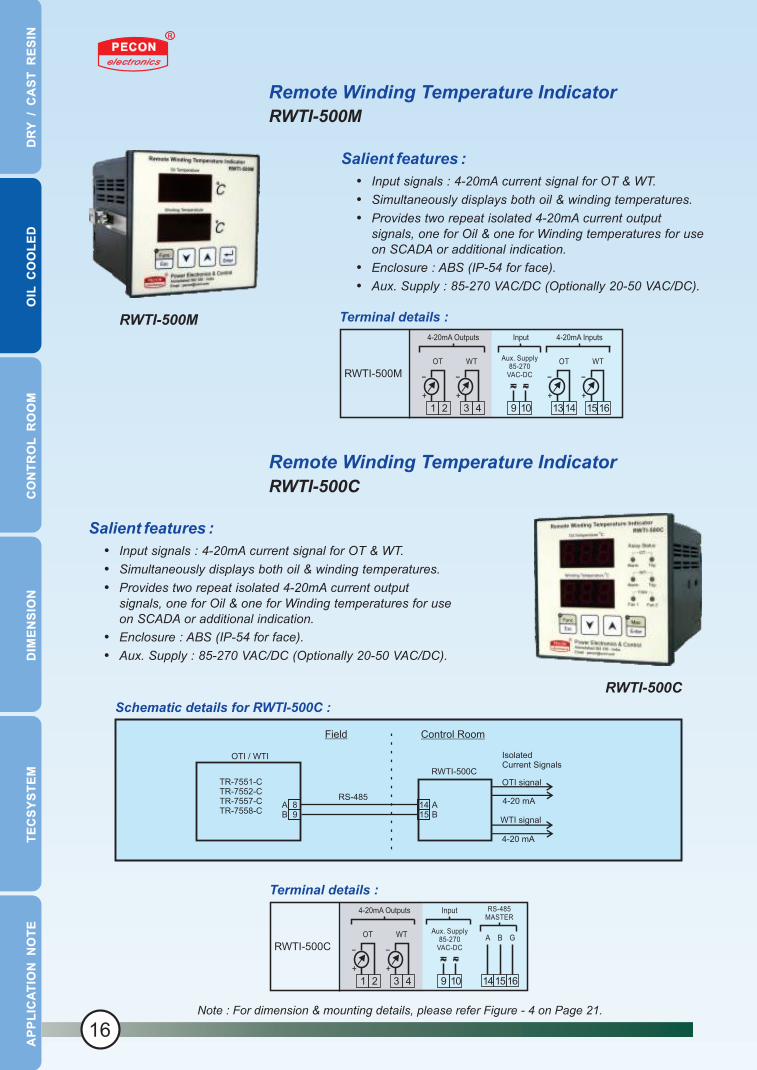
RWTI-500M
RWTI-500M
Remote Winding Temperature Indicator
RWTI-500C
RWTI-500C
Note : For dimension & mounting details, please refer Figure - 4 on Page 21.
Terminal details :
Aux. Supply85-270
VAC-DC
9 10
OT WT WTOT
1 32 4 1314 1516
+ + + +
- - - -RWTI-500M
4-20mA Outputs Input 4-20mA Inputs
D
RY
/
CA
ST
R
ES
IN
OIL
C
OO
LE
DC
ON
TR
OL
R
OO
MD
IME
NS
ION
TE
CS
YS
TE
MA
PP
LIC
AT
ION
N
OT
E
Salient features :
Input signals : 4-20mA current signal for OT & WT.
Simultaneously displays both oil & winding temperatures.
Provides two repeat isolated 4-20mA current output signals, one for Oil & one for Winding temperatures for use on SCADA or additional indication.
Enclosure : ABS (IP-54 for face).
Aux. Supply : 85-270 VAC/DC (Optionally 20-50 VAC/DC).
Terminal details :
RS-485MASTER
Aux. Supply85-270
VAC-DC
A B G
9 10
OT WT
141 32 4 1516+ +
- -RWTI-500C
4-20mA Outputs Input
Schematic details for RWTI-500C :
OTI signal
WTI signal
4-20 mA
4-20 mA
RWTI-500C
Field Control Room
IsolatedCurrent Signals
TR-7551-CTR-7552-CTR-7557-CTR-7558-C
RS-485A AB B
OTI / WTI
148159
16

RTD sensors for OTI & WTIS-07M & S-07F
LR-01
Latch Relay (LR-01)
LR-01
D
RY
/
CA
ST
R
ES
IN
OIL
C
OO
LE
DC
ON
TR
OL
R
OO
MD
IME
NS
ION
TE
CS
YS
TE
MA
PP
LIC
AT
ION
N
OT
E
Salient features & Specifications:
Suitable for all our OTI & WTI.
3 wire, Pt-100 type sensor (IEC-60751, Class B).
Temperature range : – 50 to 200 °C.
Mounting : (1) S-07M : Free rotating with ½” BSP (M) threads. (2) S-07F : Free rotating with ½” BSP (F) threads. (Other threads are available on demand).
Available in duplex style (S-07MD & S-07FD) also.
Dielectric strength : 2K VAC rms, 50 / 60 Hz for 1 min.
Salient features & Specifications :
Senses momentary contact from pressure switch and operates Alarm & Trip contacts.
Manually reset button for un-latching the relay.
LED indication for latched Alarm & Trip contacts.
Wide supply voltage, selection with simple jumper settings. AC Supply : 120 / 240 (+/- 15%) VAC, 50/60 Hz. DC Supply : 24 (+25%) / 48 (+20%) / 125 (+20%) VDC.
S-07F
S-07M
Terminal details :
InputInput Outputs
Aux. Supply(Jumper Selectable)
E
11 12 136 7 8
Alarm
PressureSwitchContact
9 10
Trip
1 2
LR-01
Voltage
Jumper SelctionJ1
2-3
3-4
1-2
2-3
3-4
120 VAC
240 VAC
24 VDC
48 VDC
125 VDC
17

Annunciator
MA-106 / MA-108 / MA-112 / MA-116
MA-116
D
RY
/
CA
ST
R
ES
IN
OIL
C
OO
LE
DC
ON
TR
OL
R
OO
MD
IME
NS
ION
TE
CS
YS
TE
MA
PP
LIC
AT
ION
N
OT
E
Salient features :
Models for 6, 8, 12 and 16 windows.
Windows size : (1) for 6 & 8 windows : 50 x 20 mm. (2) for 12 & 16 windows : 25 x 20 mm.
Isolated channels and push-buttons input.
Any ISA standard sequence - site selectable.
NO/NC channel selection can be configured on site.
Response time and flash rate are selectable.
Mounting : Flush / Panel type.
Panel cut out : 136 x 136 mm.
Enclosure : Noryl (Fire retardant material).
Aux. Supply : 85-270 VAC/DC (Optionally 20-50 VAC/DC)
Channel Inputs
1 2 3 4 5 6 7 8 9 10 11 12
1 2 3 4 5 6 7 8 9 10 11 12 13 14 15 16 17 18 19 20 21 22 23 24
RingBack
Alarm
47464445
E
394041
Aux Supply85 - 270 VAC/DC
OutputsInput
Res
et
Acc
ept
Sile
nce
F/O
Res
et
Test
Com
mon
33 34 35 36 37 38
Keys
13 14 15 16
25 26 27 28 29 30 31 32
MA-116
(16 channels)
MA-112
(12 channels)
MA-108
(8 channels)
MA-106
(6 channels)
Channel Inputs
1 2 3 4 5 6 7 8 9 10 11 12
1 2 3 4 5 6 7 8 9 10 11 12 13 14 15 16 17 18 19 20 21 22 23 24
RingBack
Alarm
47464445
E
394041
Aux Supply85 - 270 VAC/DC
OutputsInput
Res
et
Acc
ept
Sile
nce
F/O
Res
et
Test
Com
mon
33 34 35 36 37 38
Keys
Channel Inputs
1 2 3 4 5 6 7 8
1 2 3 4 5 6 7 8 9 10 11 12 13 14 15 16
RingBack
Alarm
47464445
E
394041
Aux Supply85 - 270 VAC/DC
OutputsInput
Res
et
Acc
ept
Sile
nce
F/O
Res
et
Test
Com
mon
33 34 35 36 37 38
Keys
Channel Inputs
1 2 3 4 5 6
1 2 3 4 5 6 7 8 9 10 11 12
RingBack
Alarm
47464445
E
394041
Aux Supply85 - 270 VAC/DC
OutputsInput
Res
et
Acc
ept
Sile
nce
F/O
Res
et
Test
Com
mon
33 34 35 36 37 38
Keys
Accept ResetF/O
ResetTest
Power
Power Electronics & Control MA - 116
1 2 3 4
5 6 7 8
9 10 11 12
13 14 15 16
18
Terminal details :

D
RY
/
CA
ST
R
ES
IN
OIL
C
OO
LE
DC
ON
TR
OL
R
OO
MD
IME
NS
ION
TE
CS
YS
TE
MA
PP
LIC
AT
ION
N
OT
E
UT-101 / UT-102 family
Temperature / Process Scanner
Salient features :
8 / 10 / 12 / 16 channels are available.
Sensor i/ps as per table shown below.
2 set points per channel ( Alarm & Trip ).
Relay grouping user settable as per requirement.
One relay can be programmed to operate on sensor fault.
Hysterisis ( Dead band ) user settable.
Time delay for relay operation user settable.
Channels can be added or deleted from Scanning & display.
Channel hold facility.
Programming using front key pad.
Channel number, Channel Status and parameter displayed on eight 0.5 inch displays.
Channel status are indicated using 3 mm LEDs.
Aux. Supply : 90 - 270 VAC/DC. UT-101
Parameters UT-101 UT-101/16 UT-101/SP UT-102/08 UT-102/10 UT-102/12
No of channels 16 16 16 8 10 12
Channel Inputs. Pt-100 & Cu-53
Outputs C/o contacts Open collector C/o contacts
No of outputs 8 32 32 8 6 4
Overall dimensions 192H x 96W x 335D mm 192H x 96W x 265D mm
Any one group1) PT-100 & Cu-532) T/c. J, K, E3) T/c. R, S, T
4-20 ma
/ 0-20 ma
/ 0-10 ma
19
Options :

D
RY
/
CA
ST
R
ES
IN
OIL
C
OO
LE
DC
ON
TR
OL
R
OO
MD
IME
NS
ION
TE
CS
YS
TE
MA
PP
LIC
AT
ION
N
OT
E
Figure - 3
Dimension & Mounting Details forTR-7543 & TR-7544
Notes : - All dimensions are in m.m. - Panel cutout : 92 x 92 mm.
96
96
15 110 20
92
Front View Side View
Figure - 2
Note : - All dimensions are in m.m.
X X= =
235 (+5/-0)
15
0 (
+5
/-0
)
M6 Threads
MOUNTING DETAILS
130
SIDE VIEWFRONT VIEW
265
21
55
0
Front CoverFixing Screw(Open for making connections and settings)
20
Dimension & Mounting Details forTR-7570, TR-7576, TR-7577-Cx, TR-7577-Rx,
TR-7541-M, TR-8080 spt, TR-8080-FO, TR-7551, TR-7552

D
RY
/
CA
ST
R
ES
IN
OIL
C
OO
LE
DC
ON
TR
OL
R
OO
MD
IME
NS
ION
TE
CS
YS
TE
MA
PP
LIC
AT
ION
N
OT
E
Dimension & Mounting Details for RWTI-400MC & RWTI-500MC
Figure - 4
Note : - All dimensions are in m.m. - Panel cutout : 92 x 92 mm.
96
96
10 125
90
Front View Side View
Figure - 5
Dimension & Mounting Details for SPT-04
Notes : - All dimensions are in m.m. - Din rail mount TS-35 / TS-35D as per DIN 46277-3
100 65
12
5
Front view Side View
Terminals for external connections
Figure - 6
Dimension & Mounting Details for TPR-05
Notes : - All dimensions are in m.m. - Din rail mount TS-35 / TS-35D as per DIN 46277-3
73.570
114
21

D
RY
/
CA
ST
R
ES
IN
OIL
C
OO
LE
DC
ON
TR
OL
R
OO
MD
IME
NS
ION
TE
CS
YS
TE
MA
PP
LIC
AT
ION
N
OT
E
T154
We are in techno-commercial collaboration with this leading European company,manufacturing temperature monitoring units and ventillation fans. Information
about full range of their products can be found on www.tecsystem.it
Salient features :
Four channel temperature scanner.
Temperature indication range : 0 to 240 °C.
Five relay outputs for Fault, High (Alarm) & Very High (Trip), Fan-1 & Fan-2.
4-20mA o/p for remote temperature indication / DAS / SCADA can be provided using “Module Conv 420-4”.
RS-485 MODBUS RTU slave protocol for DAS / SCADA application can be provided using “BUSMOD-8/A”.
Salient features :
Four channel temperature scanner.
Temperature indication range : 0 to 240 °C.
Four relay outputs for Fault, Fan, High (Alarm) & Very High (Trip).
Aux. Supply : 20 - 270 VAC/DC.
Winding Temperature Scanner for Dry / Cast Resin type transformers
T154
NT935
NT935
Winding Temperature Scanner for Dry / Cast Resin type transformers
22
D
RY
/
CA
ST
R
ES
IN
OIL
C
OO
LE
DC
ON
TR
OL
R
OO
MD
IME
NS
ION
TE
CS
YS
TE
MA
PP
LIC
AT
ION
N
OT
E
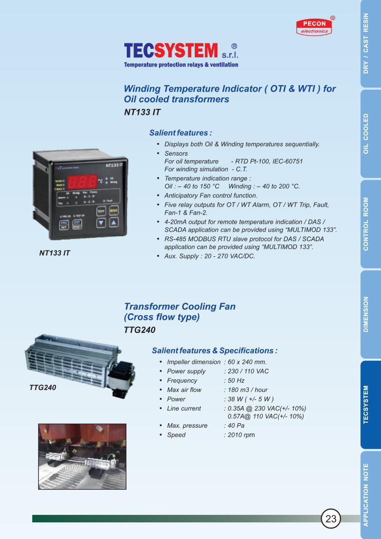
TTG240
Salient features & Specifications :
Impeller dimension : 60 x 240 mm.
Power supply : 230 / 110 VAC
Frequency : 50 Hz
Max air flow : 180 m3 / hour
Power : 38 W ( +/- 5 W )
Line current : 0.35A @ 230 VAC(+/- 10%) 0.57A@ 110 VAC(+/- 10%)
Max. pressure : 40 Pa
Speed : 2010 rpm
Transformer Cooling Fan(Cross flow type)
NT133 IT
Salient features :
Displays both Oil & Winding temperatures sequentially.
Sensors For oil temperature - RTD Pt-100, IEC-60751For winding simulation - C.T.
Temperature indication range :Oil : – 40 to 150 °C Winding : – 40 to 200 °C.
Anticipatory Fan control function.
Five relay outputs for OT / WT Alarm, OT / WT Trip, Fault, Fan-1 & Fan-2.
4-20mA output for remote temperature indication / DAS / SCADA application can be provided using “MULTIMOD 133”.
RS-485 MODBUS RTU slave protocol for DAS / SCADA application can be provided using “MULTIMOD 133”.
Aux. Supply : 20 - 270 VAC/DC.
TTG240
Winding Temperature Indicator ( OTI & WTI ) for Oil cooled transformers
NT133 IT
23

Suggestions for Installing S-02 on Dry / Cast Resin transformers
Application Note
S-02 is very reliable and has a long service life. When properly handled and installed, it will lastthroughout the useful life of the transformer and give trouble-free service. Major problems user face in temperature monitoring systems are due to mishandling of S-02, improper S-02 installations and improper wiring. Therefore, take due precautions in handling and installing S-02 and doing correct wiring.
The front portion ( about 2 - 3 cm ) of sensor S-02, contains temperature sensing element and extension joints. This part is very delicate and critical and hence needs utmost care in handling. This portion is well protected by special high temperature sleeves and in normal course nothing should happen to this. However, tapping, pulling or pushing these wires will surely damage these connections and make S-02 unusable. No heavy object should be put on S-02.
During assembly of transformers, if S-02 is pre-installed then chances of damage to S-02 are very high. It is therefore advisable to install S-02 after the assembly of transformer is complete.
Here are few suggestions for your reference,
1. Providing a tube in the interlayer winding
This is to be done at the time of winding the coils. Take about 8 to10 inches long and 5 to 6 mm ID, mica or epoxy tube. Seal it at one end with epoxy. You need to place this tube along the coil length in inter layer gap at top end of the coil and fix it firmly with fibre glass / cotton tape. This is a good and easy arrangement for housing the S-02. Once the transformer is assembled, S-02 can gently be slide / pushed into this tube. To avoid loose S-02, fill this tube with dry MgO powder and seal the upper end of the tube. This arrangement will give a very long operational life for the S-02.
This arrangement also provides a facility to replace the S-02 in case of need in future. S-02 may fail in extremely rare circumstances. To replace this defective S-02, clear this top epoxy seal carefully and take out the defective S-02. Do not try to pull the S-02 out of it’s housing without clearing this top epoxy seal. Put new S-02,and seal the tube as in earlier case.
2. Tying the tube ( after assembly of winding coils )
Take a 8 to10 inches long 5 to 6 mm ID, mica or epoxy tube, seal its one end with epoxy. You need to tie this tube vertically/length wise on the outer surface of the winding coils by fiber glass or other appropriate tape. Rest of the procedure is as described in suggestion given above.
24
D
RY
/
CA
ST
R
ES
IN
OIL
C
OO
LE
DC
ON
TR
OL
R
OO
MD
IME
NS
ION
TE
CS
YS
TE
MA
PP
LIC
AT
ION
N
OT
E

D
RY
/
CA
ST
R
ES
IN
OIL
C
OO
LE
DC
ON
TR
OL
R
OO
MD
IME
NS
ION
TE
CS
YS
TE
MA
PP
LIC
AT
ION
N
OT
E
3 - Drill hole on the top of the winding coils
Drill one hole of about 5 mm diameter and at least 25 mm depth on top side of the coil, at a suitable place, after it is casted. Refer adjacent figure. After transformer assembly, S-02 is to be placed in this hole and secured with some high temperature silicon adhesive. It might be convenient to provide one or two additional holes for installing spare S-02.
This arrangement is more common because it is easy to implement. However, this arrangement calls for extra height of insulation, making coil longer.
4. Putting S-02 in cooling ducts of windings
Some of our customers may find the above suggestions difficult to implement, They may therefore, explore the possibility of inserting S-02 in the cooling duct of low voltage coil. But in that case, care should be taken so that S-02 is not left hanging. The vibration of the sensor should be arrested using some mechanism or using some bonding / adhesive materials of suitable temperature grade.
Connections of S-02 leads to Winding Temperature Scanner ( WTS ). The most appropriate & reliable way of terminating leads of S-02, is to terminate them directly on WTS. This avoids problems arising out of loosening of intermediate terminations and wrong wiring. The only disadvantage of this method is the amount of work involved, in case S-02 is to be replaced for any reason. In some cases, it may not be possible to terminate S-02 directly on WTS. In this case, there will be a necessity to provide some intermediate termination arrangement. Here, care must be taken to select proper terminals, with following considerations
terminals are suitable for S-02 leads.
temperature ratings of these terminals.
IMPORTANT PRECAUTIONS
Never install S-02 in HV winding coils.
Avoid S-02 cable running parallel to power / high tension cables, S-02 cables should be grouped with other instrumentation cables.
Tie S-02 lead wires properly and rigidly so that they are securely in place.
The excess lead length should be accommodated in the marshalling box rather than in the transformer enclosure.
Ensure S-02 leads are provided with end ferrules of right size. Never try to solder the free ends of the sensor leads.
It is advisable to mount S-02 on the LV output side of the transformer. This would avoid the chance of accidental flash-over with HV.
Always keep the S-02 sensors in their respective packing till they are installed. All spares or extra sensors should be handled in packed condition only.
25

1. Why do I need to monitor winding temperature of a transformer ?
For economic reasons now-a-days the transformers are operated at “near limits” of temperature ratings. If suitable temperature monitoring system is not installed on the transformer, then there is a very high risk of failure of insulation leading to transformer failure and associated hazards and loss. Hence there is a need for specialized and reliable temperature surveillance system.
Although the dry / cast resin transformers are safer than oil cooled ones from the point of fire hazards, they can also cause disasters, if they exceed the rated temperature limits.
2. Do I need to monitor all three windings of the transformer ?
As dry type / cast resin transformers are usually installed at utilities where large unbalanced load is a normal condition, it is necessary to monitor all the three phase windings of the transformer.
In case of large oil cooled power transformers, they are usually installed at places where the loads are normally balanced and so in that case, monitoring only one winding’s temperature is sufficient. However, It’s always better to monitor temperature of all the three windings.
3. What is a thermal image and how does it help to estimate the winding temperature ?
Due to high voltages associated with the windings and due to insulation considerations, direct access to the windings for installing the temperature sensor is not possible. Therefore, indirect means of estimating this temperature has to be done. One of the most reliable methods to estimate winding temperature is by using “THERMAL IMAGE” formation technique. This image is formed digitally by our ( OTI&WTI ) models, by measuring top oil temperature & current flowing through the winding and doing calculations considering temperature gradient and time constant. And this image is displayed as Winding Temperature. The RTD sensor is installed on the transformer to measure “Top Oil” temperature. Winding current / load current is measured using a C.T. installed in the winding of the transformer. Temperature gradient ( dT ) and Thermal Time constant of windings are estimated by design consideration and set accordingly.
Please note that the Thermal image gives the estimated winding temperature and is not actual.
4. What is the difference between Winding Temperature Scanner (WTS) & Normal Temperature Scanner?
WTS are built specially for transformer application & the features provided in this series of scanners are in line with the requirements of transformer industry.
The operating conditions are more severe for equipments meant for transformer / switchyard application. The design for these scanners is more focused towards reliability, vibration handling, noise immunity, mounting ease, higher ambient temperatures etc. Normal temperature scanners are designed for control rooms where environmental conditions, are much less severe.
This is the reason we call these temperature scanners as “Transformer Protection Relays”. At PECON, we manufacture products for both transformer as well as for control room application. We therefore insist and suggest our customers to use appropriate equipment for specific need and application.
5. What features are essential for a Transformer protection relay (WTS, OTI&WTI) ?
For the safety, reliability & long operational life of a transformer, a good temperature surveillance system is necessary. A good temp. surveillance system should provide the following features:
Accurate temperature measurements (windings, core, oil etc etc).
Capability of warning the user of excessive transformer temperature (alarm). Capable of switching off and isolating the transformer from line in case the transformer reaches a
limiting temperature level (trip). Cooling fan control. Alarm, trip and fan controls settable over operating range. Sensor Fault monitoring and indication. Maximum temperature registering. Signal for remote indication & data logging. Should be suitable for switchyard environmental conditions.
All PECON winding temperature scanners ( Transformer protection relays ) are designed to meet these basic requirements. Most of them will have many additional features incorporated.
6. What is a RTD?
Resistance Temperature Detector or RTD for short, is a device whose resistance changes with temperature. Higher the temperature more the resistance. This change in resistance of these sensors allow us to measure the temperature.
AF Qs
26
D
RY
/
CA
ST
R
ES
IN
OIL
C
OO
LE
DC
ON
TR
OL
R
OO
MD
IME
NS
ION
TE
CS
YS
TE
MA
PP
LIC
AT
ION
N
OT
E

D
RY
/
CA
ST
R
ES
IN
OIL
C
OO
LE
DC
ON
TR
OL
R
OO
MD
IME
NS
ION
TE
CS
YS
TE
MA
PP
LIC
AT
ION
N
OT
E
7. Why RTD ? Why not thermistor ?
The main reasons which make RTD based instruments a better choice for transformer winding temperature measurements are :
RTDs are fully interchangeable.
They have very good accuracy, stability & linearity. They can be easily be tested for their healthiness, while it is very difficult to check the
healthiness of thermistors. With thermistor based equipments,
Temperature indication is not available. Only fixed temperature cut offs are possible and no settability can be given.
RTDs offer higher temperature operating range.
RTDs come at reasonable cost and are easily available.
Thermistor are mostly used in consumer goods. Their industrial use are limited to, where no indication is required and where fixed temperature cut offs with no settability is acceptable.
8. How to check RTD sensor S-02 ?
S-02 can easily be checked with ordinary multimeter. Sensor S-02 being a simple resistance, will show about 110 to 115 Ohms corresponding to room temperature between White and Red lead. Further, both the RED leads should show near zero ohms of resistance. Table below shows the resistance values at different temperatures.
All S-02s coming to you from PECON are checked and calibrated to international standards and traceable to national standards.
9. Do I have to extend all the three leads of RTD to WTS?
Yes, this is necessary to minimize errors in temp. measurement due to lead resistance of the sensor.
10. What type of wire leads should I use for extending RTDs to WTS?
Standard field cables (copper) of 1, 1.5 or 2.5 mm². (as per plant standard) can be used for RTD lead connections. It is recommended to keep RTD leads as small as possible to keep lead resistance errors minimum. Also, try to avoid intermediate joints and terminations. However, this distance in some installations can be as long as few hundred meters. With three wire leads extension, 250 meters of 1.5 mm² extension leads will cause less than 1 °C error. 2.5 mm² wire would cause even lower errors.
11. Is it safe to mount WTS directly on a transformer?
WTS is designed for marshalling box application. However, WTS can be mounted on the transformer enclosure directly, if the transformer is installed in a covered area. Make sure that the surrounding ambient conditions are within the specified limits.
Never mount WTS inside the transformer enclosure, as the temp. inside the enclosure is likely to be more than the permissible maximum ambient temperature limit.
12. What is Fan exerciser function ?
Some of the WTS & ( OTI&WTI ) are provided with this feature. This feature turns on the cooling fan for short time at regular predetermined interval (settable & selectable by the user), irrespective of the temperature of the transformer. This keeps the fan in healthy & working condition.
13. What is Anticipatory fan control function (related to OTI&WTI only) ?
This function helps in better thermal management of a transformer in comparison to conventional WTI systems. By enabling this function, WTI can anticipate the winding temperature rising above the FAN operating set point, much before it actually rises & operates the fan. Studies have proven that this leads to longer life of the transformer.
14. What is fault relay and how do I use it ?
Fault relay is provided to indicate abnormal or fault condition in WTS. These conditions are, No power to the scanner (only for WTS supplied with Electrical Fail fault)
Sensor RTD open or short circuited.
RTD(Pt - 100)
RedRed
White
Temp. Deg. C. 10.00.0 20.0 30.0 40.0
100.0 103.9 107.8 111.7 115.5Resistance Ohms
27

D
RY
/
CA
ST
R
ES
IN
OIL
C
OO
LE
DC
ON
TR
OL
R
OO
MD
IME
NS
ION
TE
CS
YS
TE
MA
PP
LIC
AT
ION
N
OT
E
1. Why do I need to monitor winding temperature of a transformer ?
For economic reasons now-a-days the transformers are operated at “near limits” of temperature ratings. If suitable temperature monitoring system is not installed on the transformer, then there is a very high risk of failure of insulation leading to transformer failure and associated hazards and loss. Hence there is a need for specialized and reliable temperature surveillance system.
Although the dry / cast resin transformers are safer than oil cooled ones from the point of fire hazards, they can also cause disasters, if they exceed the rated temperature limits.
2. Do I need to monitor all three windings of the transformer ?
As dry type / cast resin transformers are usually installed at utilities where large unbalanced load is a normal condition, it is necessary to monitor all the three phase windings of the transformer.
In case of large oil cooled power transformers, they are usually installed at places where the loads are normally balanced and so in that case, monitoring only one winding’s temperature is sufficient. However, It’s always better to monitor temperature of all the three windings.
3. What is a thermal image and how does it help to estimate the winding temperature ?
Due to high voltages associated with the windings and due to insulation considerations, direct access to the windings for installing the temperature sensor is not possible. Therefore, indirect means of estimating this temperature has to be done. One of the most reliable methods to estimate winding temperature is by using “THERMAL IMAGE” formation technique. This image is formed digitally by our ( OTI&WTI ) models, by measuring top oil temperature & current flowing through the winding and doing calculations considering temperature gradient and time constant. And this image is displayed as Winding Temperature. The RTD sensor is installed on the transformer to measure “Top Oil” temperature. Winding current / load current is measured using a C.T. installed in the winding of the transformer. Temperature gradient ( dT ) and Thermal Time constant of windings are estimated by design consideration and set accordingly.
Please note that the Thermal image gives the estimated winding temperature and is not actual.
4. What is the difference between Winding Temperature Scanner (WTS) & Normal Temperature Scanner?
WTS are built specially for transformer application & the features provided in this series of scanners are in line with the requirements of transformer industry.
The operating conditions are more severe for equipments meant for transformer / switchyard application. The design for these scanners is more focused towards reliability, vibration handling, noise immunity, mounting ease, higher ambient temperatures etc. Normal temperature scanners are designed for control rooms where environmental conditions, are much less severe.
This is the reason we call these temperature scanners as “Transformer Protection Relays”. At PECON, we manufacture products for both transformer as well as for control room application. We therefore insist and suggest our customers to use appropriate equipment for specific need and application.
5. What features are essential for a Transformer protection relay (WTS, OTI&WTI) ?
For the safety, reliability & long operational life of a transformer, a good temperature surveillance system is necessary. A good temp. surveillance system should provide the following features:
Accurate temperature measurements (windings, core, oil etc etc).
Capability of warning the user of excessive transformer temperature (alarm). Capable of switching off and isolating the transformer from line in case the transformer reaches a
limiting temperature level (trip). Cooling fan control. Alarm, trip and fan controls settable over operating range. Sensor Fault monitoring and indication. Maximum temperature registering. Signal for remote indication & data logging. Should be suitable for switchyard environmental conditions.
All PECON winding temperature scanners ( Transformer protection relays ) are designed to meet these basic requirements. Most of them will have many additional features incorporated.
6. What is a RTD?
Resistance Temperature Detector or RTD for short, is a device whose resistance changes with temperature. Higher the temperature more the resistance. This change in resistance of these sensors allow us to measure the temperature.
28


We are commited to provide technologically superior products &
high quality services to achieve total customer satisfaction.
We commit ourselves to the highest standards of quality, integrity
and excellence in all areas of business.
We pledge to monitor our performance as an on-going activity and
strive for continual improvement.
Quality Policy
At Power Electronics & Controlpopularly known as
PECON
145 / 2, G.I.D.C. Estate, Naroda, Ahmedabad - 382 330. INDIA.
Tel : +91 ( 79 ) 2281 3432, Fax : +91 ( 79 ) 2282 1397
Cell : + 91 93 2828 1537 / 1538
Email : [email protected]
Website : www.pecon-india.com
Due to continual development and change in technology, specifications are subject to change.