success d3.7 v1.0 next generation smart meter,...
TRANSCRIPT
SUCCESS D3.7 v1.0
Page 1 (51)
SUCCESS
D3.7 v1.0
Next Generation Smart Meter, Version 1
The research leading to these results has received funding from the European Union’s Horizon 2020 Research and Innovation Programme, under Grant Agreement no 700416.
Project Name SUCCESS
Contractual Delivery Date: April 30, 2017
Actual Delivery Date: April 30, 2017
Contributors: REC, TW, ENG, SYN, P3E, RWTH, ISMB
Workpackage: WP3 – Securing Smart Devices
Estimated person months: (resources spent on the deliverable)
Security: PU
Nature: R
Version: 1.0
Total number of pages: 51
Abstract: This deliverable presents the initial description of NORM concept, architecture, components and their software details. The report outlines also the necessary processes and the associated methodology towards integrating and testing, at functional level, components between WP3 and WP4 within the SUCCESS DSO Security Monitoring Platform. Keyword list: NORM, Smart meter, PMU, Physically Unclonable function, USM, Integration, Validation, Testing
Disclaimer: All information provided reflects the status of the SUCCESS project at the time of writing and may be subject to change.
SUCCESS D3.7 v1.0
Page 2 (51)
Executive Summary
The purpose of this deliverable is to present the concepts of Next Generation Open Real Time Smart Meter (NORM) and the initial stage of its developments, including the communication possibilities with the DSO Security Monitoring Centre (DSOSMC).
The deliverable presents hardware and software details of the NORM Real-time Meter. The hardware platform chosen will have all the necessary computational resources and can be used directly as a next generation smart meter incorporating tamper detection functionality and near real time measurement intervals. The NORM experiments PUFs (Physically Unclonable Function) based cryptographic approach and will be tested in laboratory and in the trials of WP 5.
Privacy by design principle is also implemented in the NORM design and implementation, giving a solution for the meter which preserves privacy of end customer but also is able through the Security Agent to send non-private data to an upper level where such data can be tested for inconsistencies and patterns which may raise cyber-security flags.
The NORM has important advantages compared with market existing smart meters and is a recommended solution for next generation of smart meters. Advantages of NORM are that:
a) It has a multi-user interface, to communicate with all actors in parallel, thus allowing multi-actor interaction directly with the data source, without needing any intermediary system;
b) It implements a special communication link with an important additional actor which is the DSO-Security Monitoring Center (DSOSMC), mediated by a Security Agent (SecA) running in SMG and extracting the relevant data for further cyber-security assessment, allowing the implementation of new cyber-attack counter-measures, in a way which preserves privacy (only non-private data is collected) and allows detection of data inconsistency at local and DSOSMC level;
c) The multi-user communication is implemented by using secure VPN technologies and by going beyond today level of security by implementing the physically unclonable function (PUF) technology, which is a much higher level of security compared with any other security technology implemented in current Smart meters.
d) NORM is aggregating through its Smart Meter Gateway (SMG) the data from two different local measuring equipment: a metrology meter and a low cost Phase Measurement Unit (PMU). With this data integration, NORM enables both smart metering and hard real-time smart grid functionalities. This is an important advancement from existing smart meters, as PMU data is now available in any metering point, enabling higher functionality in active distribution networks, specific to high renewables penetration.
e) NORM is implementing in its SMG section a new PTP synchronisation of local clock, allowing PMU functionality in wired networks without the need of costly and difficult to place GPS receiver.
f) NORM-SMG is converting classic PMU protocol (based on C37 standard) to protocols specific to smart grid SCADA (IEC61850) and to MQTT based publish-subscribe data-streams, for simple new services implementation, thus allowing a democratisation of the PMU data
g) The new low cost PMU integrated in any NORM allows wide-spread rollout of PMU technology, allowing that such information can be obtained from any point of the network.
NORM implements an SMG functionality which can be adapted and configured to be compatible with German Smart Meter Gateway (G-SMG), while providing also a superset of its functionality.
SUCCESS D3.7 v1.0
Page 3 (51)
Authors
Partner Name e-mail REC Mihai Sanduleac [email protected] Mihai Paun [email protected] ERICSSON Dhruvin Patel [email protected] ENGINEERING (ENG) Antonello Corsi [email protected] Giampaolo Fiorentino [email protected] SYNELIXIS (SYN) Artemis Voulkidis [email protected] Kostas Pramataris [email protected] Theodore Zahariadis [email protected] Rheinisch-Westfaelische Technische Hochschule Aachen ( RWTH) Antonello Monti [email protected] Padraic McKeever [email protected] Gianluca Lipari [email protected] Teamware (TW) Gianluca Zanetto [email protected] ISMB Mikhail Simonov [email protected]
SUCCESS D3.7 v1.0
Page 4 (51)
Table of Contents
1. Introduction ................................................................................................. 6
2. NORM architecture, concepts and specifications .................................... 7
The concept of unbundling the metering functions ........................................................ 7 2.1 NORM unbundling concept ............................................................................................ 8 2.2
Smart Meter Gateway ............................................................................................ 9 2.2.12.2.1.1 Main functionalities ...................................................................................... 9 2.2.1.2 Data base centric architecture ..................................................................... 9 2.2.1.3 Data privacy profiles .................................................................................. 10 Smart metrology Meter ......................................................................................... 12 2.2.2 Low cost Phase Measurement Unit (PMU) .......................................................... 12 2.2.3
NORM new functionalities compared with today Smart Meters .................................. 14 2.3 NORM new functionalities and novelties .............................................................. 14 2.3.1 NORM’s SMG compared with the German Smart Meter Gateway ...................... 15 2.3.2
Cyber-security supervision with data delivered by NORM .......................................... 22 2.4 Concept ................................................................................................................ 22 2.4.1 Rationale for selected data for DS-SMC transmission ......................................... 23 2.4.2
NORM drop of components strategy for development ................................................ 24 2.5
3. NORM main modules ................................................................................ 25
Smart Meter Gateway (SMG) ...................................................................................... 25 3.1 The core Computer platform ................................................................................ 25 3.1.1 The PUF board description .................................................................................. 25 3.1.2
3.1.2.1 PicoPUF-ID ................................................................................................ 26 3.1.2.2 Butterfly PUF .............................................................................................. 26 3.1.2.3 Arbiter PUF ................................................................................................ 26 3.1.2.4 XOR-Arbiter PUF ....................................................................................... 27 3.1.2.5 SUM Ring Oscillator PUF .......................................................................... 27
Smart Metrology Meter (SMM) ..................................................................................... 27 3.2 Introduction ........................................................................................................... 27 3.2.1 Wally A meter ....................................................................................................... 27 3.2.2 A1800 meter ......................................................................................................... 28 3.2.3
Low cost PMU .............................................................................................................. 29 3.3
4. NORM Smart Meter Gateway software .................................................... 30
Open source SMXCore ................................................................................................ 30 4.14.1.1.1 Real-time Database organisation............................................................... 30 4.1.1.2 RBAC concept ............................................................................................ 30 As having a database centric approach, all actors can access only the database
and cannot have direct connection between them, in order not to transfer data which is nor controlled by the user. ................................................... 30
4.1.1.3 MQTT communication ................................................................................ 30 4.1.1.4 Meter communication ................................................................................. 31
PMU protocol converter ............................................................................................... 32 4.2 PTP functionality .......................................................................................................... 32 4.3 PUF security modules .................................................................................................. 33 4.4
Bootstrapping services ......................................................................................... 34 4.4.1 Authentication services ........................................................................................ 34 4.4.2 Encryption services .............................................................................................. 34 4.4.3
NORM Security Agent .................................................................................................. 35 4.5 Introduction ........................................................................................................... 35 4.5.1 Security Agent Architectural ................................................................................. 36 4.5.2
NORM Security Administration Agent .......................................................................... 38 4.6
5. Test plan for individual components ....................................................... 39
BASIC SMG software .................................................................................................. 39 5.1
SUCCESS D3.7 v1.0
Page 5 (51)
Security Agent .............................................................................................................. 39 5.2 PUF functionality .......................................................................................................... 39 5.3 PTP synchronisation .................................................................................................... 40 5.4 Low cost PMU .............................................................................................................. 40 5.5 EMC test for PUF ......................................................................................................... 40 5.6
6. References ................................................................................................. 42
7. List of Abbreviations ................................................................................ 44
Annex A. List of data subject of being reported by NORM-SecA to DSO-SMC ............................................................................................................ 45
A.1 Real-time data validation (cases named RTxx) ........................................................... 45 A.2 Communication on Public IP Networks (PIPN) such as Internet (cases CPIPxx) ....... 46 A.3 3. SMG Internal Database access ............................................................................... 47 A.4 SMG System health (SyHxx) ....................................................................................... 48 A.5 SMG Commands validation (CMDxx) .......................................................................... 48 A.6 Anti-tampering events (ATEVxx) .................................................................................. 49 A.7 Power System Metada (PMdxx) .................................................................................. 49 A.8 Other category (YYYxx) ............................................................................................... 50
List of data subject of NOT being reported by NORM-SecA to DSO-SMC 51
SUCCESS D3.7 v1.0
Page 6 (51)
1. Introduction
NORM is developed in SUCCESS project as the Next Generation Open Real Time Smart Meter based on the unbundled meter concept already developed in Nobel Grid, by adding to the SMM and SMX parts of the Nobel Grid project additional hardware and software modules. NORM is an open platform where new functionalities can be added to standard meters within the Smart Meter Gateway, an enhanced version of SMX. NORM could be used as a new stand-alone meter (when equipped with the proper metrology and hard-real time features) or it could be used to expand legacy meters with more functionalities and securities and with added hard real time features such as PMU functionality. In this sense, SUCCESS offers an open solution compatible with the past but open to future developments. For the prototype implementation, a low cost embedded computer will be used, with specific target being the Raspberry PI 3 (RPI3) platform, which will be used to run Linux operating system with application software to integrate a market existing meter and a low cost PMU, thus the RPI3 platform acting as a Smart Meter Gateway (SMG). This deliverable describes the main architecture of NORM, principles of design and the current situation of each module, as first drop of functionalities developed during the project period. The deliverable will be followed by second and third variants of NORM, which will stabilize and finalize the details of the product, including feed-backs from the deployments in the three trial sites. In this deliverable, three main objectives are pursued:
To provide the basic architecture of the NORM and concepts and the first variant functionalities to allow refinements and complete integration of the functional blocks during the second stage of the project,
To show the integration of NORM in the DS-SMG, and to To pave the way towards a well-defined certification strategy plan.
The document is structured as follows: Section 2 introduces architecture, concepts and general specification. Section 3 focuses on describing each module of NORM: SMG, low cost PMU, smart meter. Section 4 describes the current situation for the software functionalities inside the module. Section 5 provides the initial plan for the testing phase of individual components of NORM and the connection to D-SMC. Section 6 is for concluding the work inside the deliverable and to present next steps. The last sections deal with references and abbreviations.
SUCCESS D3.7 v1.0
Page 7 (51)
2. NORM architecture, concepts and specifications
In this section are presented the main concepts and basic specifications of NORM.
The concept of unbundling the metering functions 2.1
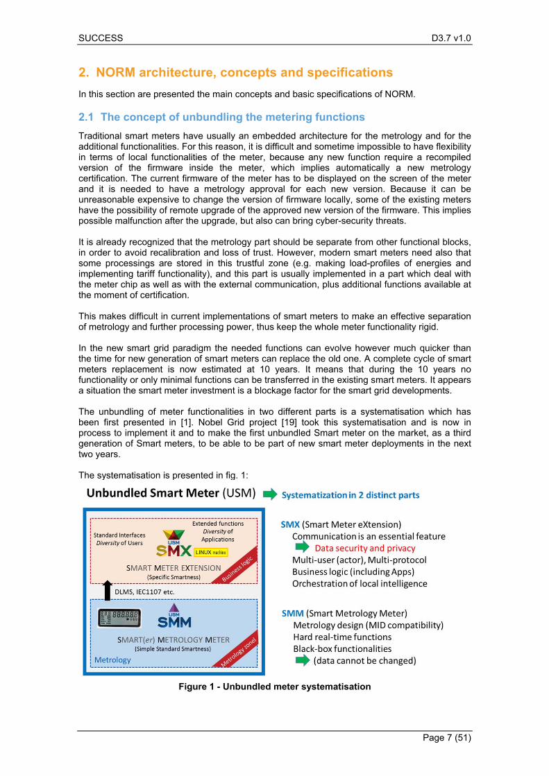
Traditional smart meters have usually an embedded architecture for the metrology and for the additional functionalities. For this reason, it is difficult and sometime impossible to have flexibility in terms of local functionalities of the meter, because any new function require a recompiled version of the firmware inside the meter, which implies automatically a new metrology certification. The current firmware of the meter has to be displayed on the screen of the meter and it is needed to have a metrology approval for each new version. Because it can be unreasonable expensive to change the version of firmware locally, some of the existing meters have the possibility of remote upgrade of the approved new version of the firmware. This implies possible malfunction after the upgrade, but also can bring cyber-security threats. It is already recognized that the metrology part should be separate from other functional blocks, in order to avoid recalibration and loss of trust. However, modern smart meters need also that some processings are stored in this trustful zone (e.g. making load-profiles of energies and implementing tariff functionality), and this part is usually implemented in a part which deal with the meter chip as well as with the external communication, plus additional functions available at the moment of certification. This makes difficult in current implementations of smart meters to make an effective separation of metrology and further processing power, thus keep the whole meter functionality rigid. In the new smart grid paradigm the needed functions can evolve however much quicker than the time for new generation of smart meters can replace the old one. A complete cycle of smart meters replacement is now estimated at 10 years. It means that during the 10 years no functionality or only minimal functions can be transferred in the existing smart meters. It appears a situation the smart meter investment is a blockage factor for the smart grid developments. The unbundling of meter functionalities in two different parts is a systematisation which has been first presented in [1]. Nobel Grid project [19] took this systematisation and is now in process to implement it and to make the first unbundled Smart meter on the market, as a third generation of Smart meters, to be able to be part of new smart meter deployments in the next two years. The systematisation is presented in fig. 1:
Figure 1 - Unbundled meter systematisation
SUCCESS D3.7 v1.0
Page 8 (51)
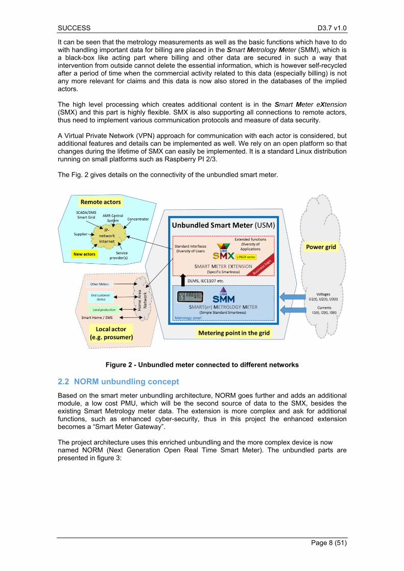
It can be seen that the metrology measurements as well as the basic functions which have to do with handling important data for billing are placed in the Smart Metrology Meter (SMM), which is a black-box like acting part where billing and other data are secured in such a way that intervention from outside cannot delete the essential information, which is however self-recycled after a period of time when the commercial activity related to this data (especially billing) is not any more relevant for claims and this data is now also stored in the databases of the implied actors. The high level processing which creates additional content is in the Smart Meter eXtension (SMX) and this part is highly flexible. SMX is also supporting all connections to remote actors, thus need to implement various communication protocols and measure of data security. A Virtual Private Network (VPN) approach for communication with each actor is considered, but additional features and details can be implemented as well. We rely on an open platform so that changes during the lifetime of SMX can easily be implemented. It is a standard Linux distribution running on small platforms such as Raspberry PI 2/3. The Fig. 2 gives details on the connectivity of the unbundled smart meter.
Figure 2 - Unbundled meter connected to different networks
NORM unbundling concept 2.2
Based on the smart meter unbundling architecture, NORM goes further and adds an additional module, a low cost PMU, which will be the second source of data to the SMX, besides the existing Smart Metrology meter data. The extension is more complex and ask for additional functions, such as enhanced cyber-security, thus in this project the enhanced extension becomes a “Smart Meter Gateway”. The project architecture uses this enriched unbundling and the more complex device is now named NORM (Next Generation Open Real Time Smart Meter). The unbundled parts are presented in figure 3:
SUCCESS D3.7 v1.0
Page 9 (51)
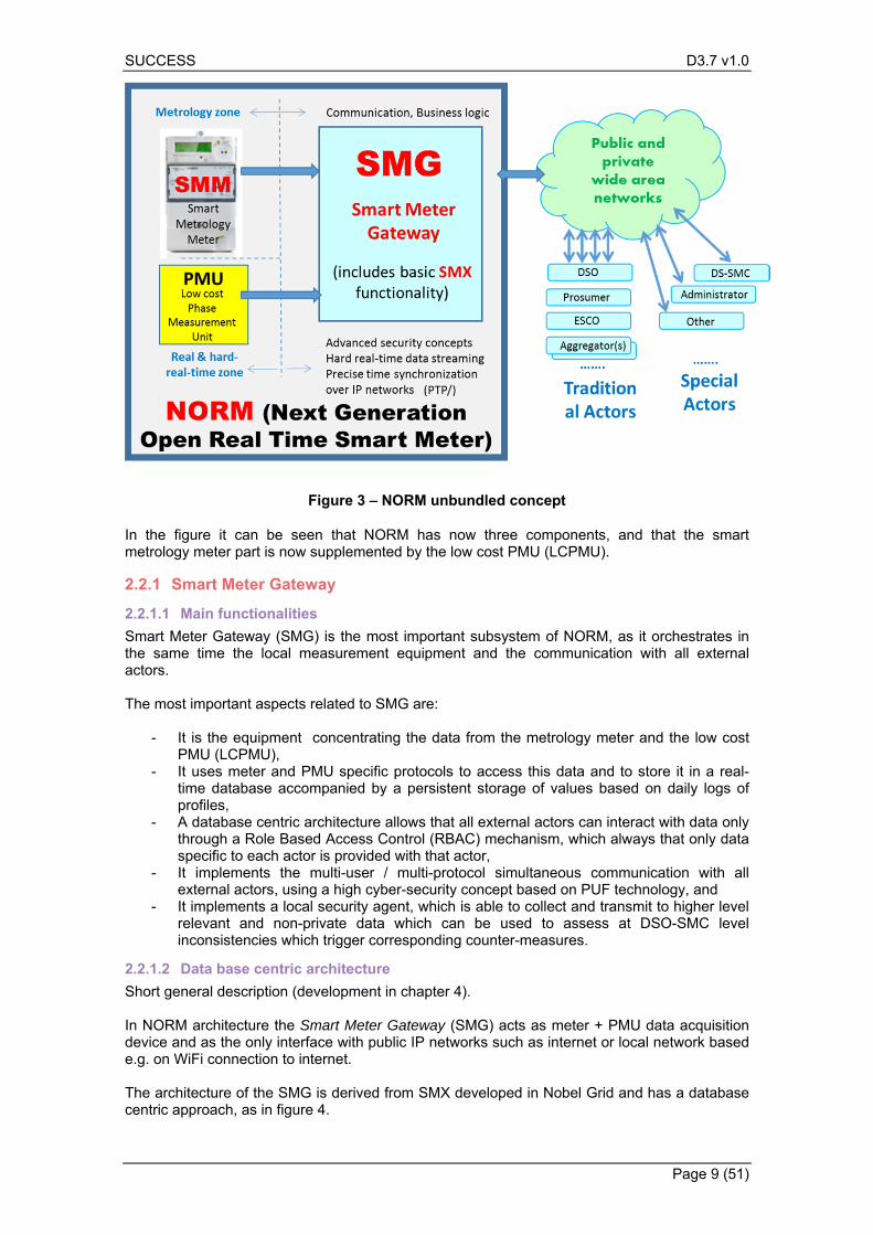
Figure 3 – NORM unbundled concept
In the figure it can be seen that NORM has now three components, and that the smart metrology meter part is now supplemented by the low cost PMU (LCPMU).
Smart Meter Gateway 2.2.1
2.2.1.1 Main functionalities
Smart Meter Gateway (SMG) is the most important subsystem of NORM, as it orchestrates in the same time the local measurement equipment and the communication with all external actors. The most important aspects related to SMG are:
- It is the equipment concentrating the data from the metrology meter and the low cost PMU (LCPMU),
- It uses meter and PMU specific protocols to access this data and to store it in a real-time database accompanied by a persistent storage of values based on daily logs of profiles,
- A database centric architecture allows that all external actors can interact with data only through a Role Based Access Control (RBAC) mechanism, which always that only data specific to each actor is provided with that actor,
- It implements the multi-user / multi-protocol simultaneous communication with all external actors, using a high cyber-security concept based on PUF technology, and
- It implements a local security agent, which is able to collect and transmit to higher level relevant and non-private data which can be used to assess at DSO-SMC level inconsistencies which trigger corresponding counter-measures.
2.2.1.2 Data base centric architecture
Short general description (development in chapter 4). In NORM architecture the Smart Meter Gateway (SMG) acts as meter + PMU data acquisition device and as the only interface with public IP networks such as internet or local network based e.g. on WiFi connection to internet. The architecture of the SMG is derived from SMX developed in Nobel Grid and has a database centric approach, as in figure 4.
SUCCESS D3.7 v1.0
Page 10 (51)
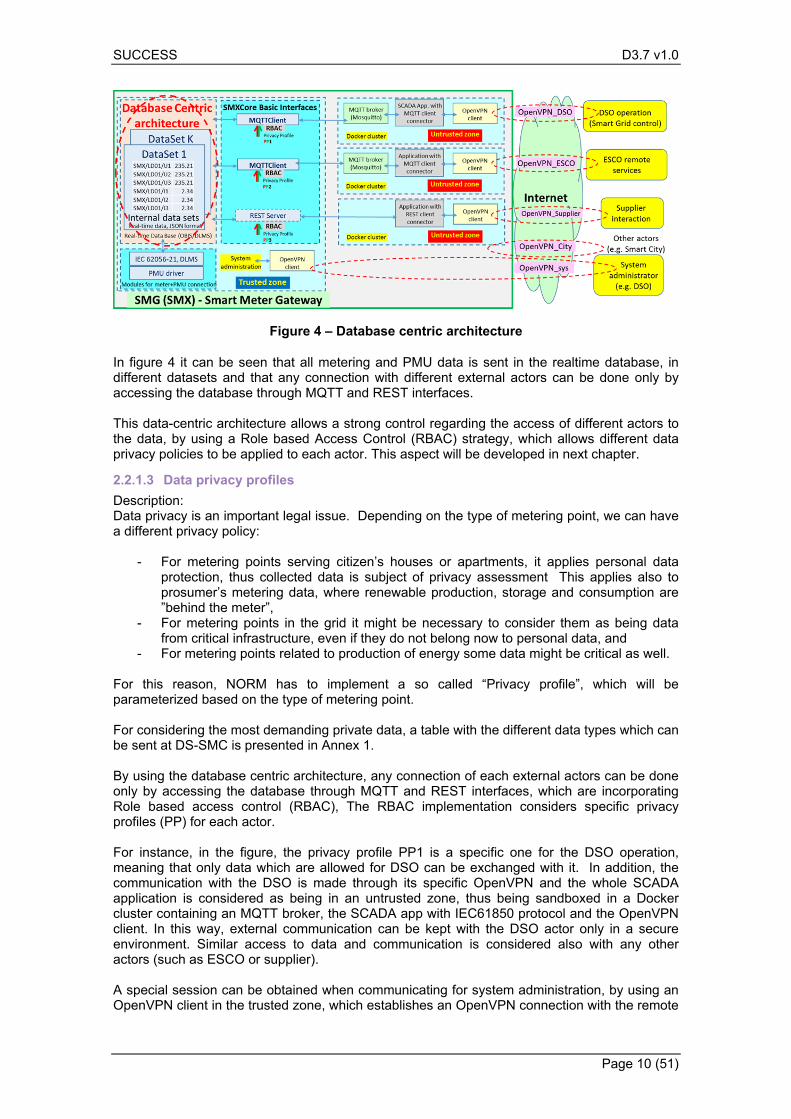
Figure 4 – Database centric architecture
In figure 4 it can be seen that all metering and PMU data is sent in the realtime database, in different datasets and that any connection with different external actors can be done only by accessing the database through MQTT and REST interfaces. This data-centric architecture allows a strong control regarding the access of different actors to the data, by using a Role based Access Control (RBAC) strategy, which allows different data privacy policies to be applied to each actor. This aspect will be developed in next chapter.
2.2.1.3 Data privacy profiles
Description: Data privacy is an important legal issue. Depending on the type of metering point, we can have a different privacy policy:
- For metering points serving citizen’s houses or apartments, it applies personal data protection, thus collected data is subject of privacy assessment This applies also to prosumer’s metering data, where renewable production, storage and consumption are ”behind the meter”,
- For metering points in the grid it might be necessary to consider them as being data from critical infrastructure, even if they do not belong now to personal data, and
- For metering points related to production of energy some data might be critical as well. For this reason, NORM has to implement a so called “Privacy profile”, which will be parameterized based on the type of metering point. For considering the most demanding private data, a table with the different data types which can be sent at DS-SMC is presented in Annex 1. By using the database centric architecture, any connection of each external actors can be done only by accessing the database through MQTT and REST interfaces, which are incorporating Role based access control (RBAC), The RBAC implementation considers specific privacy profiles (PP) for each actor. For instance, in the figure, the privacy profile PP1 is a specific one for the DSO operation, meaning that only data which are allowed for DSO can be exchanged with it. In addition, the communication with the DSO is made through its specific OpenVPN and the whole SCADA application is considered as being in an untrusted zone, thus being sandboxed in a Docker cluster containing an MQTT broker, the SCADA app with IEC61850 protocol and the OpenVPN client. In this way, external communication can be kept with the DSO actor only in a secure environment. Similar access to data and communication is considered also with any other actors (such as ESCO or supplier). A special session can be obtained when communicating for system administration, by using an OpenVPN client in the trusted zone, which establishes an OpenVPN connection with the remote
SUCCESS D3.7 v1.0
Page 11 (51)
system administrator, which usually is also the DSO, but another entity which is entitled to make the NORM/SMG maintenance. Privacy profiles PP1, .. PP3 etc. are a combination of rights of data access which respect both:
a) country specific rules (provided by national law, country regulator and by the DSO), named Country Privacy Profile (CPP), and
b) user specific rules, described in User Privacy profile UPP.
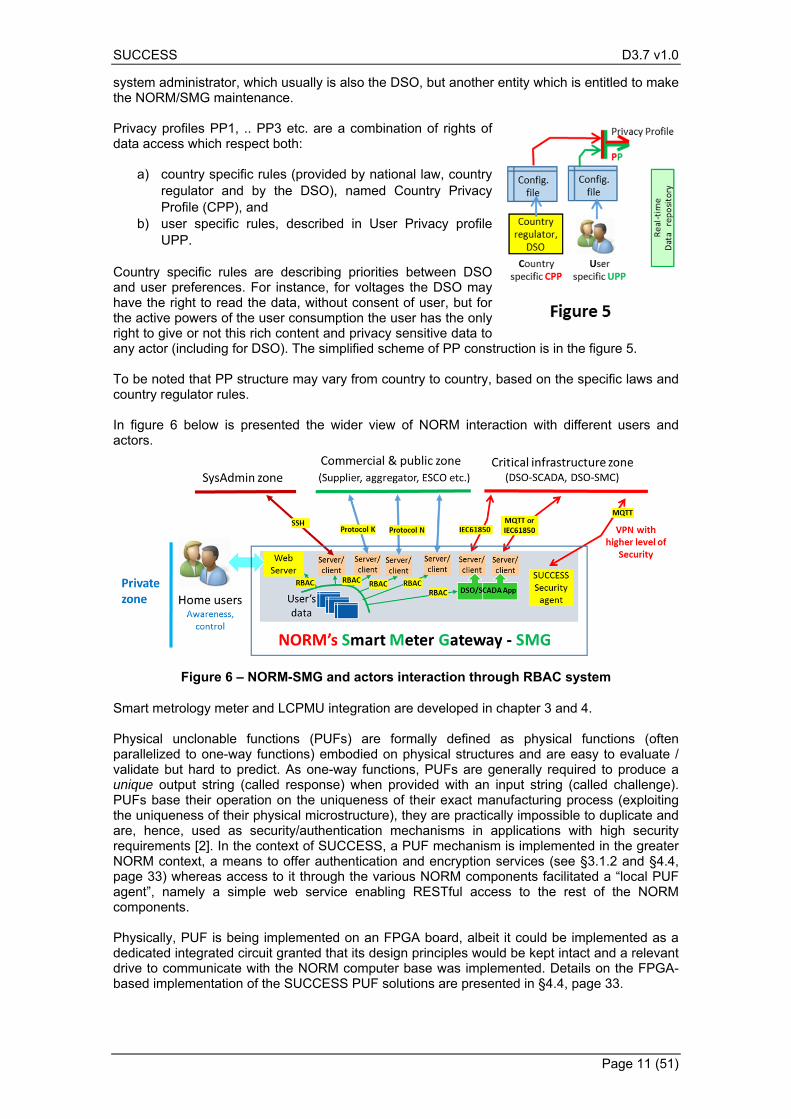
Country specific rules are describing priorities between DSO and user preferences. For instance, for voltages the DSO may have the right to read the data, without consent of user, but for the active powers of the user consumption the user has the only right to give or not this rich content and privacy sensitive data to any actor (including for DSO). The simplified scheme of PP construction is in the figure 5. To be noted that PP structure may vary from country to country, based on the specific laws and country regulator rules. In figure 6 below is presented the wider view of NORM interaction with different users and actors.
Figure 6 – NORM-SMG and actors interaction through RBAC system
Smart metrology meter and LCPMU integration are developed in chapter 3 and 4. Physical unclonable functions (PUFs) are formally defined as physical functions (often parallelized to one-way functions) embodied on physical structures and are easy to evaluate / validate but hard to predict. As one-way functions, PUFs are generally required to produce a unique output string (called response) when provided with an input string (called challenge). PUFs base their operation on the uniqueness of their exact manufacturing process (exploiting the uniqueness of their physical microstructure), they are practically impossible to duplicate and are, hence, used as security/authentication mechanisms in applications with high security requirements [2]. In the context of SUCCESS, a PUF mechanism is implemented in the greater NORM context, a means to offer authentication and encryption services (see §3.1.2 and §4.4, page 33) whereas access to it through the various NORM components facilitated a “local PUF agent”, namely a simple web service enabling RESTful access to the rest of the NORM components. Physically, PUF is being implemented on an FPGA board, albeit it could be implemented as a dedicated integrated circuit granted that its design principles would be kept intact and a relevant drive to communicate with the NORM computer base was implemented. Details on the FPGA-based implementation of the SUCCESS PUF solutions are presented in §4.4, page 33.
SUCCESS D3.7 v1.0
Page 12 (51)
More information about NORM specific data security based on PUF technology is described in chapters 3 and 4.
Smart metrology Meter 2.2.2
The Smart metrology meter (SMM) is the metrological part of NORM. In the SUCCESS project it is considered as being a market existing meter, which is chosen as being a meter present in the sites of the demonstrators. Our project does not concentrate on a new SMM, but on the new architecture of NORM, based on unbundling the different critical components, as already has been presented. The metrology aspect of this part is essential for keeping the NORM as having the status of a Smart meter, because it keeps the legal power of metrology, which allows that the measurements can be used in billing, thus being usable in case of legal disputes. Acting as a legal black-box containing un-modifiable data, SMM can be certified by its own, without affecting the other components of NORM. In the practical demonstration of NORM architecture, the market existing meter is connected to SMG through a serial connection, and this is the only possible interaction path between SMM and SMG, based on standard protocols available for the meter, such as DLMS/COSEM (“Device Language Message specification” and “COmpanion Specification for Energy Metering”, details being available at www.dlms.com).
Low cost Phase Measurement Unit (PMU) 2.2.3
Phase measurement units (PMUs) are new equipment in the distribution network, being at the moment more used in the transmission system, operated by Transmission and System Operator (TSO). The principle of measuring of angles of voltages and currents on phases relies essentially on the fact that there is a very good synchronisation of time between different PMUs. Due to this requirement, toady PMUs are using GPS as main source of time synchronisation, which need in fact GPS receiver mounted in such a place that the sky and its satellites are visible. For the TSO the costs involved in deploying a GPS based PMU are acceptable, even if they are high (usually more than 1000 Euros, for some models 3000 to 5000 Euros). Our project is targeting the large deployment of basic PMU functionality in any smart meter of the low voltage distribution grid, which is proposed with the following approach: only voltages are subject of PMU measurements (voltages phases are the most important for assessing active grid or microgrid functionality) and synchronisation is made through a combination of high speed IP-network and 5G connectivity. As the SMG is a Linux machine, the default way of making time synchronisation in NTP (Network Time Protocol) synchronisation. This solution allows good synchronisation between different SMG of down to 20 milliseconds between the devices. However, this is unacceptable for phase measurements, considering that a resolution of one degree (from 360 degrees in a period of 20 milliseconds) means a time resolution of 55 microseconds. For this reason the project considers a much better synchronisation by investigating the PTP (Precise Time Protocol) use. The PTP module is able to synchronize the CPU time base at much higher accuracy than NTP does. It refers to IEEE 1588 – 2008 standard [8] and even though the accuracy expectations of PTP synchronized clocks is in the order of 100 ns, based on the quality of network connection, realistic synchronisation between 10 and 100 microseconds are expected in the SMG by using cabled Ethernet based networks. The basic principle is similar to NTP protocol, where computers and other devices that have a clock are connected in a network and form a hierarchy of time sources in which time is distributed from top to bottom. The devices on top are normally synchronized to a reference time source (e.g. a timing signal from a GPS receiver). Devices “below” periodically exchange timestamps with their time sources in order to measure the offset of their clocks. The clocks are
SUCCESS D3.7 v1.0
Page 13 (51)
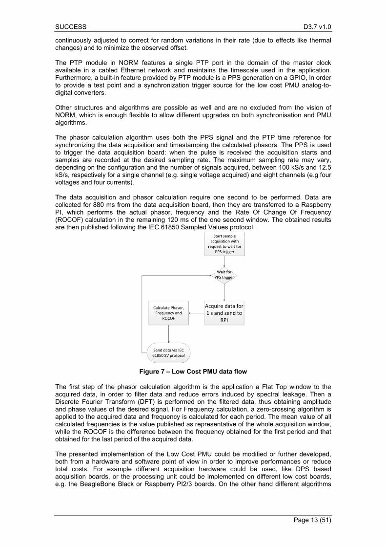
continuously adjusted to correct for random variations in their rate (due to effects like thermal changes) and to minimize the observed offset. The PTP module in NORM features a single PTP port in the domain of the master clock available in a cabled Ethernet network and maintains the timescale used in the application. Furthermore, a built-in feature provided by PTP module is a PPS generation on a GPIO, in order to provide a test point and a synchronization trigger source for the low cost PMU analog-to-digital converters. Other structures and algorithms are possible as well and are no excluded from the vision of NORM, which is enough flexible to allow different upgrades on both synchronisation and PMU algorithms. The phasor calculation algorithm uses both the PPS signal and the PTP time reference for synchronizing the data acquisition and timestamping the calculated phasors. The PPS is used to trigger the data acquisition board: when the pulse is received the acquisition starts and samples are recorded at the desired sampling rate. The maximum sampling rate may vary, depending on the configuration and the number of signals acquired, between 100 kS/s and 12.5 kS/s, respectively for a single channel (e.g. single voltage acquired) and eight channels (e.g four voltages and four currents). The data acquisition and phasor calculation require one second to be performed. Data are collected for 880 ms from the data acquisition board, then they are transferred to a Raspberry PI, which performs the actual phasor, frequency and the Rate Of Change Of Frequency (ROCOF) calculation in the remaining 120 ms of the one second window. The obtained results are then published following the IEC 61850 Sampled Values protocol.
Figure 7 – Low Cost PMU data flow
The first step of the phasor calculation algorithm is the application a Flat Top window to the acquired data, in order to filter data and reduce errors induced by spectral leakage. Then a Discrete Fourier Transform (DFT) is performed on the filtered data, thus obtaining amplitude and phase values of the desired signal. For Frequency calculation, a zero-crossing algorithm is applied to the acquired data and frequency is calculated for each period. The mean value of all calculated frequencies is the value published as representative of the whole acquisition window, while the ROCOF is the difference between the frequency obtained for the first period and that obtained for the last period of the acquired data. The presented implementation of the Low Cost PMU could be modified or further developed, both from a hardware and software point of view in order to improve performances or reduce total costs. For example different acquisition hardware could be used, like DPS based acquisition boards, or the processing unit could be implemented on different low cost boards, e.g. the BeagleBone Black or Raspberry PI2/3 boards. On the other hand different algorithms
SUCCESS D3.7 v1.0
Page 14 (51)
could be used for windowing or phasor calculation and in general software implementation could be different. However, this well fits in the NORM vision and unbundled design, since it is not closely tied to a specific implementation or hardware product.
NORM new functionalities compared with today Smart Meters 2.3
NORM is considered as future equipment to replace existing smart meters in the next wave of smart meters deployments, to be considered as a third generation.
NORM new functionalities and novelties 2.3.1
Today Smart meters are considered as being part of a second generation, with large deployments in the last years over Europe. The first generation, mainly based on very low PLC communication in most situations and GPRS for some segments, started the deployment around year 2005 in early adopting countries such as Italy or Sweden. The second generation is based on quicker PLC communication, and on GPRS/3G communication in some particular cases. Second generation has more complex functionalities, such as net-metering, to be prepared for prosumers, and on complex structures of tariffs, to enable more flexible participation to market opportunities. In first generation of Smart Meters the only communication path is usually only to the DSO. The second generation gives in some situations also an interface to the end customer, e.g. with Linky in France or through the mandatory local interface in Belgium. Cyber-security is implemented on the PLC communication to the concentrator, which is the path to DSO. There is no concept of multi-user communication directly to the meter, thus any information need to pass through DSO. NORM has new features when compared with the existing smart meters that are currently available in the market. Main features are presented below:
a) Compared to existing SM, the NORM-SMG has a a multi-user interface, where all users/actors can communicate in parallel, thus allowing multi-actor interaction directly with the data source, without needing any intermediary system; in addition to energy actors implemented in [19], SMG is implementing also the communication with an important additional actor which is the DSO-Security Monitoring Center (DSOSMC), mediated by a Security Agent (SecA) running in SMG and extracting the relevant data for DSOSMC.
b) With the DSO-SMC communication, new cyber-attack counter-measures can be implemented, in such a way which preserves privacy (only non-private data is collected) and allows detection of data inconsistency from local level, due to redundancy of measured data (meter and PMU) to higher DSO-SMC level, where wide area data is checked as a whole
c) The multi-user connectivity is implemented in a secure way, based on Linux supported security features, using VPN technologies such as OpenVPN, first implemented in [19]; NORM’s SMG is going further and implements the new PUF technology, which is a much higher level of security compared with any other security technology implemented in current Smart meters.
d) SMG is aggregating data from two different local measuring equipment: a metrology meter and a low cost PMU. With this data integration, NORM enables both smart metering and hard real-time smart grid functionalities. This is an important advancement from existing smart meters, as PMU data is now available in any metering point, enabling higher functionality in active distribution networks, specific to high renewables penetration.
e) SMG is implementing new PTP synchronisation of local clock, enabled by 5G communication and allowing PMU functionality without the need of costly and difficult to place GPS receiver.
SUCCESS D3.7 v1.0
Page 15 (51)
f) SMG is converting classic PMU protocol (based on C37 standard) to protocols specific to smart grid SCADA (IEC61850) and MQTT based publish-subscribe for simple new services implementation, thus allowing a democratisation of the PMU data
g) The new low cost PMU integrated in NORM allows democratisation of PMU technology, allowing that such information can be obtained from any point of the network.
A comparison between today state of the art smart meters and NORM functionalities is given in the table below. No. Existing smart meters
functionality NORM functionality Observations
1 One user interface (usually towards DSO)
Multi-user / multi-protocol interface
The multi-user feature enables services
2 Metering data for billing Metering data and PMU-based grid data
Allows both smart metering and smart grid
3 Time synchronisation of one second
Precise synchronisation under one millisecond
Allows synchronous PMU measurements
4 Medium up to high cyber-security
Enhanced cyber-security with PUF technology
Higher trust in smart metering
5 Low to medium grid data redundancy
Redundancy for grid data such as voltage and frequency
Allows local check of data consistency
6 No intrinsic concept for holistic cyber-security approach
Special security agent is running to support higher DSO-SMC functionality
Non-privacy intrusive security monitoring by design
NORM’s SMG compared with the German Smart Meter Gateway 2.3.2
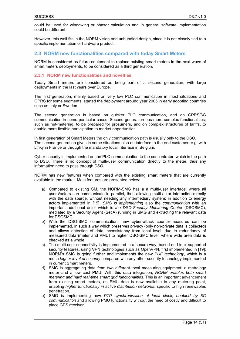
The gateway of NORM has the same name as has also the German Smart Meter Gateway. For reasons of clarity, an assessment regarding what is similar and what is different in NORM’s SMG (NORM-SMG) compared with German SMG (G-SMG) is given below. Germany is the only country which comes with a concept of Smart Meter Gateway, which acts as an access point for the data from all meters of the customer (electricity, gas, water etc.), as well as for the home area network data. For this Gateway functionality, it needs to be considered the Data Access Manager (DAM) approach for handling the data, which is defined in [42]. In the German concept, the data from any such source can be retrieved in the so called Smart Meter Gateway – the responsible for getting the metering data is the Smart Meter Gateway, which belongs to the end-customer. Moreover, even if the access rights for the data may be the responsibility of the end-customer, a third party – which is neither DSO nor Supplier – is managing the access rights. The role of managing the data access rights is kept by a special body for data access rights management, a role different from the DSOs (although they are managing data rights in other data access models), because this is an independent party, similar to the Central Hub in some other European countries. The role of storing the data is however different also to the Central Hub model, as the data is always at the Smart Metering System Gateway level, thus at the end-customer level, bringing empowerment to the citizen, protecting their privacy and reducing their privacy concerns, and giving the option to modulate the policy. From this point of view the German model with DAM is the most modern and advanced in EU/Europe. Some figures from the German gateway specification are below presented, with explanations regarding the relevant aspects of the approach. Figure 8 and 9 from [42] show the three possible networks:
SUCCESS D3.7 v1.0
Page 16 (51)
- the Home Area Network (HAN) - for the home appliances and for local user, - the Local Metrology Network (LMN) - for different types of local meters and - the Wide Area Network (WAN) – to be assimilated with public IP networks such as
internet.
A security module is considered to be associated to the German Smart Meter Gateway. In 1.4.6.1 - Handling of Meter Data [42], is stated that: “The Gateway is responsible for handling Meter Data. It receives the Meter Data from the Meter(s), processes it, stores it and submits it to external entities. Moreover, the TOE (Target of Evaluation) utilises Processing Profiles to determine which data shall be sent to which component or external entity. A Processing Profile defines:
How the Meter Data must be processed, Which processed Meter Data must be sent and in which time intervals, To which component or external entity has to be sent, Data is signed using which key material, Data is encrypted using which key material, Whether processed Meter Data shall be pseudonymised or not, and Which pseudonym shall be used to send the data.”
Figure 8 - The G-SMG architecture general overview
Figure 9 shows the type of actors which can be found in each of the G-SMG networks. For instance, the “consumer” (or end-user) and the “Service technician” can interact only from the HAN, thus are not able to make any remote connection and inspect / modify something from WAN. The “Authorized external Entity” and the “Gateway Administrator” can access the SMGW only from the Wide Area Network (WAN). While these rules give clarity about the access to various resources, the NORM approach is more flexible and gives the possibility for each actor to access its data in a different VPN, thus preserving adequate cyber-security between the different users.
SUCCESS D3.7 v1.0
Page 17 (51)
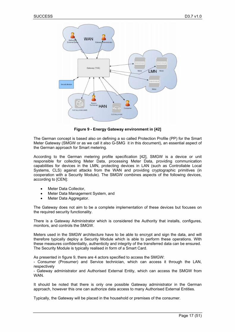
Figure 9 - Energy Gateway environment in [42]
The German concept is based also on defining a so called Protection Profile (PP) for the Smart Meter Gateway (SMGW or as we call it also G-SMG it in this document), an essential aspect of the German approach for Smart metering. According to the German metering profile specification [42], SMGW is a device or unit responsible for collecting Meter Data, processing Meter Data, providing communication capabilities for devices in the LMN, protecting devices in LAN (such as Controllable Local Systems, CLS) against attacks from the WAN and providing cryptographic primitives (in cooperation with a Security Module). The SMGW combines aspects of the following devices, according to [CEN]:
Meter Data Collector, Meter Data Management System, and Meter Data Aggregator.
The Gateway does not aim to be a complete implementation of these devices but focuses on the required security functionality. There is a Gateway Administrator which is considered the Authority that installs, configures, monitors, and controls the SMGW. Meters used in the SMGW architecture have to be able to encrypt and sign the data, and will therefore typically deploy a Security Module which is able to perform these operations. With these measures confidentiality, authenticity and integrity of the transferred data can be ensured. The Security Module is typically realised in form of a Smart Card. As presented in figure 9, there are 4 actors specified to access the SMGW: - Consumer (Prosumer) and Service technician, which can access it through the LAN, respectively - Gateway administrator and Authorised External Entity, which can access the SMGW from WAN. It should be noted that there is only one possible Gateway administrator in the German approach, however this one can authorize data access to many Authorised External Entities. Typically, the Gateway will be placed in the household or premises of the consumer.
SUCCESS D3.7 v1.0
Page 18 (51)
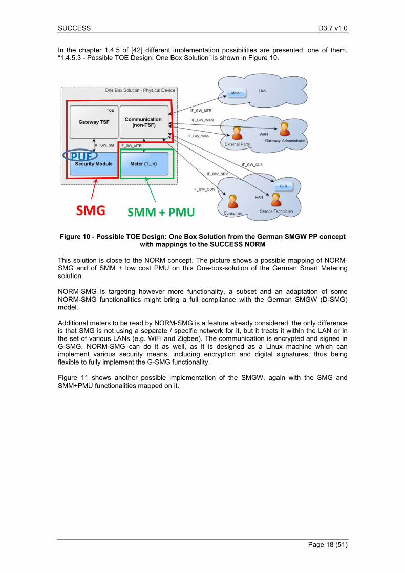
In the chapter 1.4.5 of [42] different implementation possibilities are presented, one of them, “1.4.5.3 - Possible TOE Design: One Box Solution” is shown in Figure 10.
Figure 10 - Possible TOE Design: One Box Solution from the German SMGW PP concept with mappings to the SUCCESS NORM
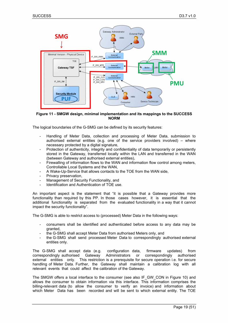
This solution is close to the NORM concept. The picture shows a possible mapping of NORM-SMG and of SMM + low cost PMU on this One-box-solution of the German Smart Metering solution. NORM-SMG is targeting however more functionality, a subset and an adaptation of some NORM-SMG functionalities might bring a full compliance with the German SMGW (D-SMG) model. Additional meters to be read by NORM-SMG is a feature already considered, the only difference is that SMG is not using a separate / specific network for it, but it treats it within the LAN or in the set of various LANs (e.g. WiFi and Zigbee). The communication is encrypted and signed in G-SMG. NORM-SMG can do it as well, as it is designed as a Linux machine which can implement various security means, including encryption and digital signatures, thus being flexible to fully implement the G-SMG functionality. Figure 11 shows another possible implementation of the SMGW, again with the SMG and SMM+PMU functionalities mapped on it.
SUCCESS D3.7 v1.0
Page 19 (51)
Figure 11 - SMGW design, minimal implementation and its mappings to the SUCCESS NORM
The logical boundaries of the G-SMG can be defined by its security features:
- Handling of Meter Data, collection and processing of Meter Data, submission to authorised external entities (e.g. one of the service providers involved) – where necessary protected by a digital signature,
- Protection of authenticity, integrity and confidentiality of data temporarily or persistently stored in the Gateway, transferred locally within the LAN and transferred in the WAN (between Gateway and authorised external entities),
- Firewalling of information flows to the WAN and information flow control among meters, Controllable Local Systems and the WAN,
- A Wake-Up-Service that allows contacts to the TOE from the WAN side, - Privacy preservation, - Management of Security Functionality, and - Identification and Authentication of TOE use.
An important aspect is the statement that “it is possible that a Gateway provides more functionality than required by this PP. In those cases however, it is essential that the additional functionality is separated from the evaluated functionality in a way that it cannot impact the security functionality”. The G-SMG is able to restrict access to (processed) Meter Data in the following ways:
- consumers shall be identified and authenticated before access to any data may be granted,
- the G-SMG shall accept Meter Data from authorised Meters only, and - the G-SMG shall send processed Meter Data to correspondingly authorised external
entities only. The G-SMG shall accept data (e.g. configuration data, firmware updates) from correspondingly authorised Gateway Administrators or correspondingly authorised external entities only. This restriction is a prerequisite for secure operation i.e. for secure handling of Meter Data. Further, the Gateway shall maintain a calibration log with all relevant events that could affect the calibration of the Gateway. The SMGW offers a local interface to the consumer (see also IF_GW_CON in Figure 10) and allows the consumer to obtain information via this interface. This information comprises the billing-relevant data (to allow the consumer to verify an invoice) and information about which Meter Data has been recorded and will be sent to which external entity. The TOE
SUCCESS D3.7 v1.0
Page 20 (51)
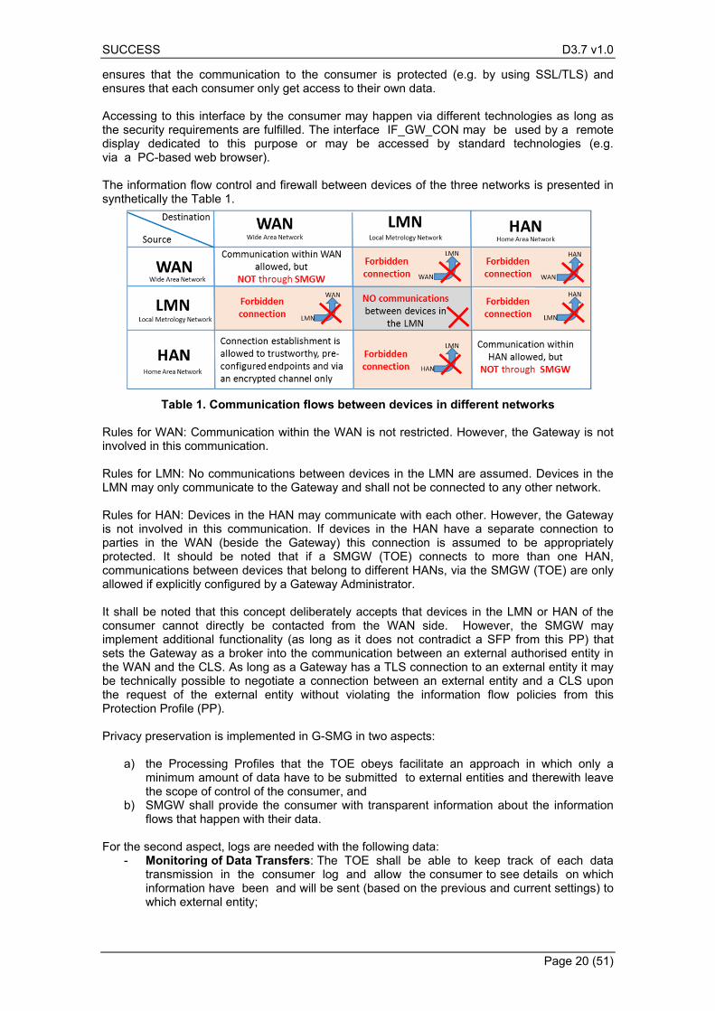
ensures that the communication to the consumer is protected (e.g. by using SSL/TLS) and ensures that each consumer only get access to their own data. Accessing to this interface by the consumer may happen via different technologies as long as the security requirements are fulfilled. The interface IF_GW_CON may be used by a remote display dedicated to this purpose or may be accessed by standard technologies (e.g. via a PC-based web browser). The information flow control and firewall between devices of the three networks is presented in synthetically the Table 1.
Table 1. Communication flows between devices in different networks Rules for WAN: Communication within the WAN is not restricted. However, the Gateway is not involved in this communication. Rules for LMN: No communications between devices in the LMN are assumed. Devices in the LMN may only communicate to the Gateway and shall not be connected to any other network. Rules for HAN: Devices in the HAN may communicate with each other. However, the Gateway is not involved in this communication. If devices in the HAN have a separate connection to parties in the WAN (beside the Gateway) this connection is assumed to be appropriately protected. It should be noted that if a SMGW (TOE) connects to more than one HAN, communications between devices that belong to different HANs, via the SMGW (TOE) are only allowed if explicitly configured by a Gateway Administrator. It shall be noted that this concept deliberately accepts that devices in the LMN or HAN of the consumer cannot directly be contacted from the WAN side. However, the SMGW may implement additional functionality (as long as it does not contradict a SFP from this PP) that sets the Gateway as a broker into the communication between an external authorised entity in the WAN and the CLS. As long as a Gateway has a TLS connection to an external entity it may be technically possible to negotiate a connection between an external entity and a CLS upon the request of the external entity without violating the information flow policies from this Protection Profile (PP). Privacy preservation is implemented in G-SMG in two aspects:
a) the Processing Profiles that the TOE obeys facilitate an approach in which only a minimum amount of data have to be submitted to external entities and therewith leave the scope of control of the consumer, and
b) SMGW shall provide the consumer with transparent information about the information flows that happen with their data.
For the second aspect, logs are needed with the following data:
- Monitoring of Data Transfers: The TOE shall be able to keep track of each data transmission in the consumer log and allow the consumer to see details on which information have been and will be sent (based on the previous and current settings) to which external entity;

SUCCESS D3.7 v1.0
Page 21 (51)
- Configuration Reporting: The TOE shall provide detailed and complete reporting in the consumer log of each security and privacy-relevant configuration setting. Additional to device specific configuration settings the consumer log shall contain the parameters of each Processing Profile. The consumer log shall contain the configured addresses for internal and external entities including the CLS
- Audit Log and Monitoring: The TOE shall provide all audit data from the consumer log at the user interface IF_GW_CON. Access to the consumer log shall only be possible after successful authentication and only to information that the consumer has permission to (i.e. that has been recorded based on events belonging to the consumer)
The Gateway provides authorised Gateway Administrators with functionality to manage the behaviour of the security functions and to update the TOE. This Protection Profile defines a minimum set of management functions that must be implemented by each Gateway seeking conformance to this PP. Only authorised Gateway Administrators may be able to use the management functionality of the Gateway (while the Security Module is used for the authentication of the Gateway Administrator) and that the management of the Gateway shall only be possible from the WAN side interface. It should also be noted that in the proposed metering infrastructure it should be possible to change the Smart Meter Gateway Administrator (SMGW Admin) rights and assignments also during the operation the of Smart Meter Gateways. There are rules to do it without causing disruption of supply, or gaps in the collection and analysis of measured values. The Smart Metering Gateway Administrator is important actor. According to German rules, market participants entrusted with this task are:
- Transmission network operator (Übertragungsnetzbetreiber (ÜNB)), - Distribution system operator (Verteilnetzbetreiber (VNB)), - Measuring point operator (Messstellenbetreiber (MSB)), - Communication provider, and - Other/state institutions.
Parts of the cryptographic functionality used in the SMGW shall be provided by a Security Module. The Security Module of G-SMG (or SMGW) provides strong cryptographic functionality, random number generation, secure storage of secrets and supports the authentication of the Gateway Administrator. Even if the Security Module is a different IT product and not part of the SMGW, it is physically embedded into SMGW and is protected by the same level of physical protection. The German model has been studied and considered in the Smart Meter Architecture because it gives important details of the German metering architecture, which are useful for our metering concept. For the time being we consider the German metering architecture based on SMGW as being a specific and more restricted implementation, which can be implemented with our proposed NORM consisting of more flexible SMG, SMM and low cost PMU parts. We will not implement SMGW, as none of our demonstrators is located in Germany. We will use, however, these principles of SMGW that have shown to be useful for the more general concept of an USM and feasible in our five demonstrators. In the SUCCESS Metering Architecture there are two Administrators, similar with what is implemented in the Nobel Grid USM: one which has to do with the mandatory country regulations, such that it can secure data which is requested by the law – practically the regulated data management, and one which is the Local user, which can administrate un-regulated data, including more private data which may be needed for advanced energy services, for which the data access and management should be fully decided by the local user. With this approach, we aim to enhance the flexibility of data management and empower the citizen more than it is possible by the restricted solutions of today. The German case of data
SUCCESS D3.7 v1.0
Page 22 (51)
management is a very good example to follow, adapt and improve for the goals of SUCCESS project.
Cyber-security supervision with data delivered by NORM 2.4
Concept 2.4.1
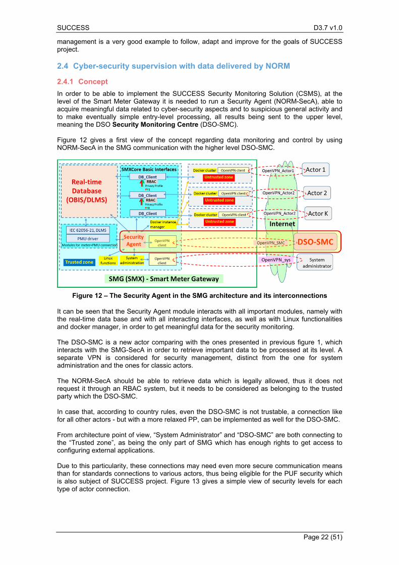
In order to be able to implement the SUCCESS Security Monitoring Solution (CSMS), at the level of the Smart Meter Gateway it is needed to run a Security Agent (NORM-SecA), able to acquire meaningful data related to cyber-security aspects and to suspicious general activity and to make eventually simple entry-level processing, all results being sent to the upper level, meaning the DSO Security Monitoring Centre (DSO-SMC). Figure 12 gives a first view of the concept regarding data monitoring and control by using NORM-SecA in the SMG communication with the higher level DSO-SMC.
Figure 12 – The Security Agent in the SMG architecture and its interconnections
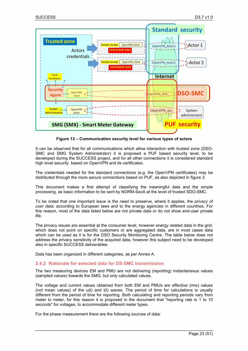
It can be seen that the Security Agent module interacts with all important modules, namely with the real-time data base and with all interacting interfaces, as well as with Linux functionalities and docker manager, in order to get meaningful data for the security monitoring. The DSO-SMC is a new actor comparing with the ones presented in previous figure 1, which interacts with the SMG-SecA in order to retrieve important data to be processed at its level. A separate VPN is considered for security management, distinct from the one for system administration and the ones for classic actors. The NORM-SecA should be able to retrieve data which is legally allowed, thus it does not request it through an RBAC system, but it needs to be considered as belonging to the trusted party which the DSO-SMC. In case that, according to country rules, even the DSO-SMC is not trustable, a connection like for all other actors - but with a more relaxed PP, can be implemented as well for the DSO-SMC. From architecture point of view, “System Administrator” and “DSO-SMC” are both connecting to the “Trusted zone”, as being the only part of SMG which has enough rights to get access to configuring external applications. Due to this particularity, these connections may need even more secure communication means than for standards connections to various actors, thus being eligible for the PUF security which is also subject of SUCCESS project. Figure 13 gives a simple view of security levels for each type of actor connection.
SUCCESS D3.7 v1.0
Page 23 (51)
Figure 13 – Communication security level for various types of actors
It can be observed that for all communications which allow interaction with trusted zone (DSO-SMC and SMG System Administrator) it is proposed a PUF based security level, to be developed during the SUCCESS project, and for all other connections it is considered standard high level security based on OpenVPN and its certificates. The credentials needed for the standard connections (e.g. the OpenVPN certificates) may be distributed through the more secure connections based on PUF, as also depicted in figure 3. This document makes a first attempt of classifying the meaningful data and the simple processing, as basic information to be sent by NORM-SecA at the level of trusted SDO-SMC. To be noted that one important issue is the need to preserve, where it applies, the privacy of user data, according to European laws and to the energy agencies in different countries. For this reason, most of the data listed below are not private data or do not show end-user private life. The privacy issues are essential at the consumer level, however energy related data in the grid, which does not point on specific customers or are aggregated data, are in most cases data which can be used as it is for the DSO Security Monitoring Centre. The table below does not address the privacy sensitivity of the acquired data, however this subject need to be developed also in specific SUCCESS deliverables. Data has been organized in different categories, as per Annex A.
Rationale for selected data for DS-SMC transmission 2.4.2
The two measuring devices EM and PMU are not delivering (reporting) instantaneous values (sampled values) towards the SMG, but only calculated values. The voltage and current values obtained from both EM and PMUs are effective (rms) values (not mean values) of the u(t) and i(t) waves. The period of time for calculations is usually different from the period of time for reporting. Both calculating and reporting periods vary from meter to meter, for this reason it is proposed in the document that "reporting rate is 1 to 10 seconds" for voltages, to accommodate different meter types. For the phase measurement there are the following sources of data:
SUCCESS D3.7 v1.0
Page 24 (51)
A. in 3-phased EM, we can have only two angles (fi1-2, fi2-3), the third is redundant if it is calculated (the sum need to be 360 degrees), or is used for validation if it is measured as well. Different meters are doing it in different ways. Moreover, the angle of U1 is considered zero, so again we might have only fi(U2), fi(U3). There is no voltage angle information for mono-phase meters (as you expected), because the angle is always considered zero (as a reference). For mono-phase meters there is only angle between voltage and current. I initially wanted to put it in the list and I still consider it, but I am still thinking on privacy issues, as it gives some indirect hints on consumed power (which is highly sensitive regarding privacy)
B. for PMUs it is different, they have for all phases angles which can be different from zero, . Moreover, there is angle also for mono-phase meters (because the reference is given by the precise time)
NORM drop of components strategy for development 2.5
The project aims to develop NORM in two steps: initial drop of components, to be finalised in M12 (milestone MS5) and final drop of NORM components, scheduled for M24 (milestone MS6). NORM is a complex equipment based on several components: SMM, low cost PMU (LCPMU), PUF technology and NORM-SMG. The initial drop of NORM components is a system which uses a market existing smart meter acting as an SMM and 3 x RPI2/3 subsystems, each with the following role:
- RPI2/3#1 is the system which implements LCPMU - RPI2/3#2 is the system which implements the PUF cyber-security technology - RPI2/3#3 is the system which implements the NORM-SMG
The advantage of this approach relies in the fact that each important component can be tested separately, in order to achieve a level of functionality needed for further system integration. The final drop of NORM components is a system which integrates the 3 x RPI2/3 subsystems, in only two subsystems:
- RPI2/3#1 is the system which implements LCPMU - RPI2/3#2 is the system which implements the NORM-SMG with the PUF cyber-security
technology The NORM functionality as a whole and the functionality of each component is described in this deliverable. The NORM final drop of components will be described in next deliverable D3.8
SUCCESS D3.7 v1.0
Page 25 (51)
3. NORM main modules
The NORM modules are based on the unbundled concept, as described before. This chapter presents the modules seen as black-box components, and describe hardware and basic functionality of the modules. Software components involved in NORM are however described in next chapter 4.
Smart Meter Gateway (SMG) 3.1
In this section are presented the basic description of NORM’s SMG.
The core Computer platform 3.1.1
The core computer has the following sub-modules:
- The Single Board Computer, which is a RPI3 solution in the SUCCESS project, - A shied board, which supports some simple functionalities not included in RPI3.
The following description of the components apply:
The PUF board description 3.1.2
It is the intention of SUCCESS to implement the PUF functionality on top of an FPGA board. The specification requirements related to the selection of the FPGA board indicate that the FPGA board should be able to:
1. seamlessly integrate with the NORM core computer platform (namely the RPI3 board) through a Serial Peripheral Interface (SPI) bus interface to enable read and write access to the internal FPGA registers;
2. be of low cost, matching the low-cost objective of the NORM; 3. process a large number of PUF requests, i.e. generation of a response based on a
challenge, as well as encryption requests.
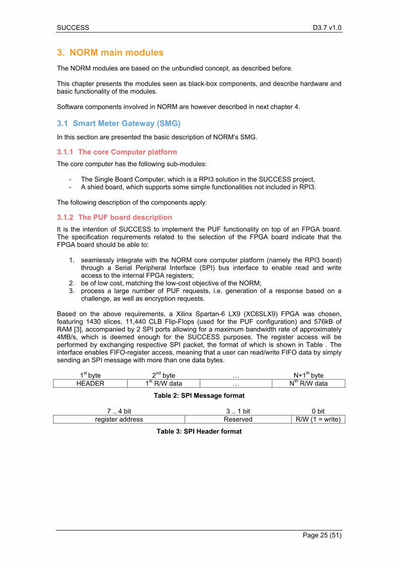
Based on the above requirements, a Xilinx Spartan-6 LX9 (XC6SLX9) FPGA was chosen, featuring 1430 slices, 11,440 CLB Flip-Flops (used for the PUF configuration) and 576kB of RAM [3], accompanied by 2 SPI ports allowing for a maximum bandwidth rate of approximately 4MB/s, which is deemed enough for the SUCCESS purposes. The register access will be performed by exchanging respective SPI packet, the format of which is shown in Table . The interface enables FIFO-register access, meaning that a user can read/write FIFO data by simply sending an SPI message with more than one data bytes.
1st byte 2nd byte … N+1th byte HEADER 1st R/W data … Nth R/W data
Table 2: SPI Message format
7 .. 4 bit 3 .. 1 bit 0 bit register address Reserved R/W (1 = write)
Table 3: SPI Header format
SUCCESS D3.7 v1.0
Page 26 (51)
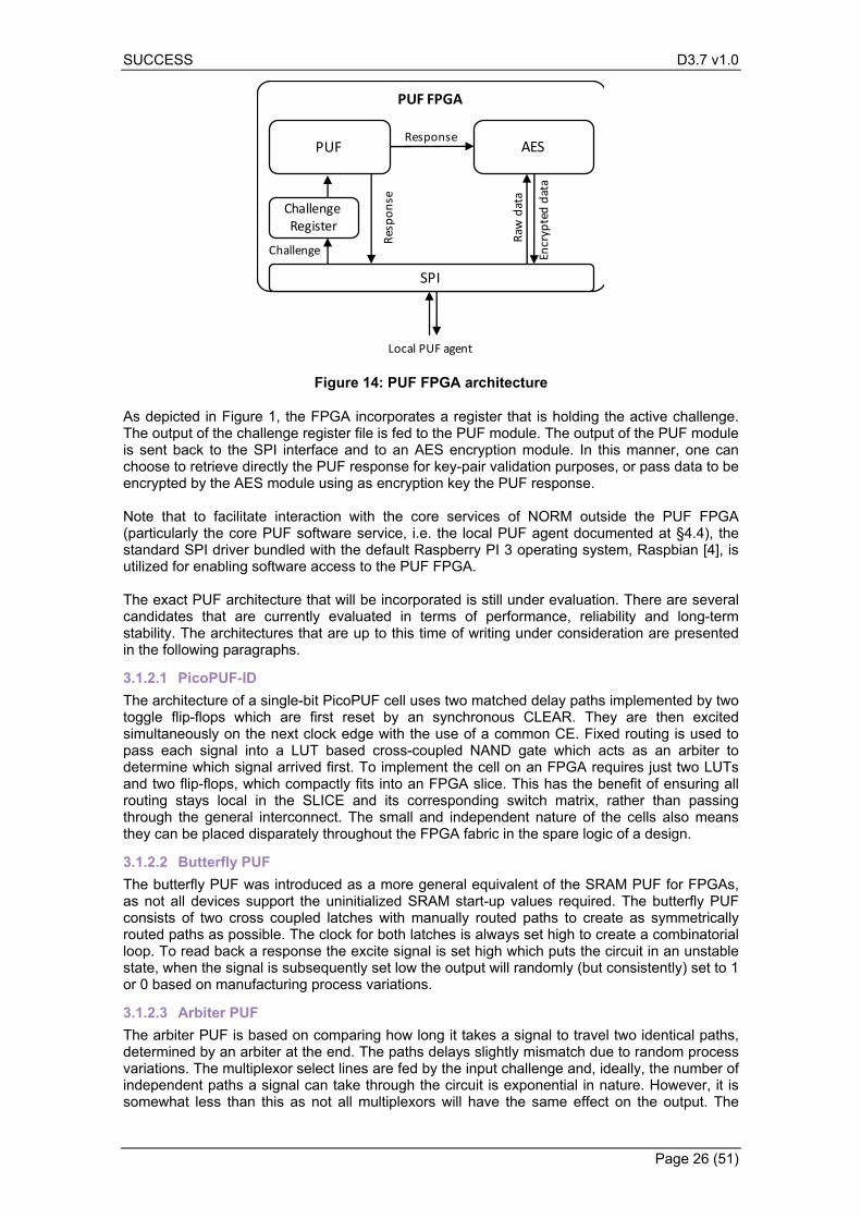
Figure 14: PUF FPGA architecture
As depicted in Figure 1, the FPGA incorporates a register that is holding the active challenge. The output of the challenge register file is fed to the PUF module. The output of the PUF module is sent back to the SPI interface and to an AES encryption module. In this manner, one can choose to retrieve directly the PUF response for key-pair validation purposes, or pass data to be encrypted by the AES module using as encryption key the PUF response. Note that to facilitate interaction with the core services of NORM outside the PUF FPGA (particularly the core PUF software service, i.e. the local PUF agent documented at §4.4), the standard SPI driver bundled with the default Raspberry PI 3 operating system, Raspbian [4], is utilized for enabling software access to the PUF FPGA. The exact PUF architecture that will be incorporated is still under evaluation. There are several candidates that are currently evaluated in terms of performance, reliability and long-term stability. The architectures that are up to this time of writing under consideration are presented in the following paragraphs.
3.1.2.1 PicoPUF-ID
The architecture of a single-bit PicoPUF cell uses two matched delay paths implemented by two toggle flip-flops which are first reset by an synchronous CLEAR. They are then excited simultaneously on the next clock edge with the use of a common CE. Fixed routing is used to pass each signal into a LUT based cross-coupled NAND gate which acts as an arbiter to determine which signal arrived first. To implement the cell on an FPGA requires just two LUTs and two flip-flops, which compactly fits into an FPGA slice. This has the benefit of ensuring all routing stays local in the SLICE and its corresponding switch matrix, rather than passing through the general interconnect. The small and independent nature of the cells also means they can be placed disparately throughout the FPGA fabric in the spare logic of a design.
3.1.2.2 Butterfly PUF
The butterfly PUF was introduced as a more general equivalent of the SRAM PUF for FPGAs, as not all devices support the uninitialized SRAM start-up values required. The butterfly PUF consists of two cross coupled latches with manually routed paths to create as symmetrically routed paths as possible. The clock for both latches is always set high to create a combinatorial loop. To read back a response the excite signal is set high which puts the circuit in an unstable state, when the signal is subsequently set low the output will randomly (but consistently) set to 1 or 0 based on manufacturing process variations.
3.1.2.3 Arbiter PUF
The arbiter PUF is based on comparing how long it takes a signal to travel two identical paths, determined by an arbiter at the end. The paths delays slightly mismatch due to random process variations. The multiplexor select lines are fed by the input challenge and, ideally, the number of independent paths a signal can take through the circuit is exponential in nature. However, it is somewhat less than this as not all multiplexors will have the same effect on the output. The
Encryp
teddata
PUF FPGA
SPI
PUF AES
Challenge
Response
Response
Raw
data
Local PUF agent
Challenge Register
SUCCESS D3.7 v1.0
Page 27 (51)
restricted routing options available in FPGAs also means that a straightforward implementation will result in heavily biased designs as the difference between the delay paths will be determined by the interconnect delay rather than any random process variations.
3.1.2.4 XOR-Arbiter PUF
The XOR-arbiter increases the complexity of the circuit to thwart modelling based attacks. The basic premise of this approach is to combine the output of many arbiter circuits using an XOR gate. Several different architectures are possible, each with varying trade-offs. Examples include simply XORing the output of many parallel arbiter circuits, or using the same arbiter circuit and deriving subsequent challenges from the base challenge.
3.1.2.5 SUM Ring Oscillator PUF
The SUM Ring Oscillator PUF provides a much larger challenge space than the original RO PUF. Pre-determined pairs of RO are summed together, with the challenge determining the sign of the frequency difference. A thresholding step is then used to return a single bit. This also has the effect of de-biasing the bit outputs.
Smart Metrology Meter (SMM) 3.2
Introduction 3.2.1
The Smart Metrology Meter is the NORM component which is supporting the traditional legally recognized metering. For this, a market existing meter is used in the project, to integrate the metering data in the SMG, together with the PMU data, and to send it at that level to various actors, including the Security Agent, which is delivering data to higher levels for assessing anomalous situations which may raise flags for possible cyber-attacks situations. In our project we have integrated energy meters which are found in the demonstrators premises, as follows:
- In the Italian trial site (Terni) we have integrated the Wally A meter, which is a combined power quality and energy meter.
- In the Romanian trial site the DSO uses extensively Itron meters of type SL7000 and Elster meters of type A1800. As in the Electrica region with renewables there are more Elster meters, the A1800 meter has been used as SMM part of the NORM.
In the first level of integration (first drop of NORM) we already integrated these two types of meters. Below can be found some data acquired by SMG by using these types of SMM.
Wally A meter 3.2.2
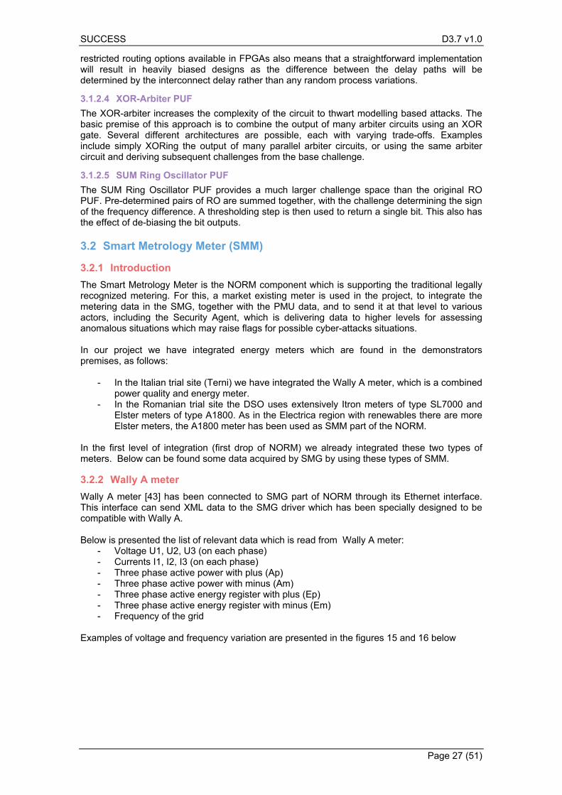
Wally A meter [43] has been connected to SMG part of NORM through its Ethernet interface. This interface can send XML data to the SMG driver which has been specially designed to be compatible with Wally A. Below is presented the list of relevant data which is read from Wally A meter:
- Voltage U1, U2, U3 (on each phase) - Currents I1, I2, I3 (on each phase) - Three phase active power with plus (Ap) - Three phase active power with minus (Am) - Three phase active energy register with plus (Ep) - Three phase active energy register with minus (Em) - Frequency of the grid
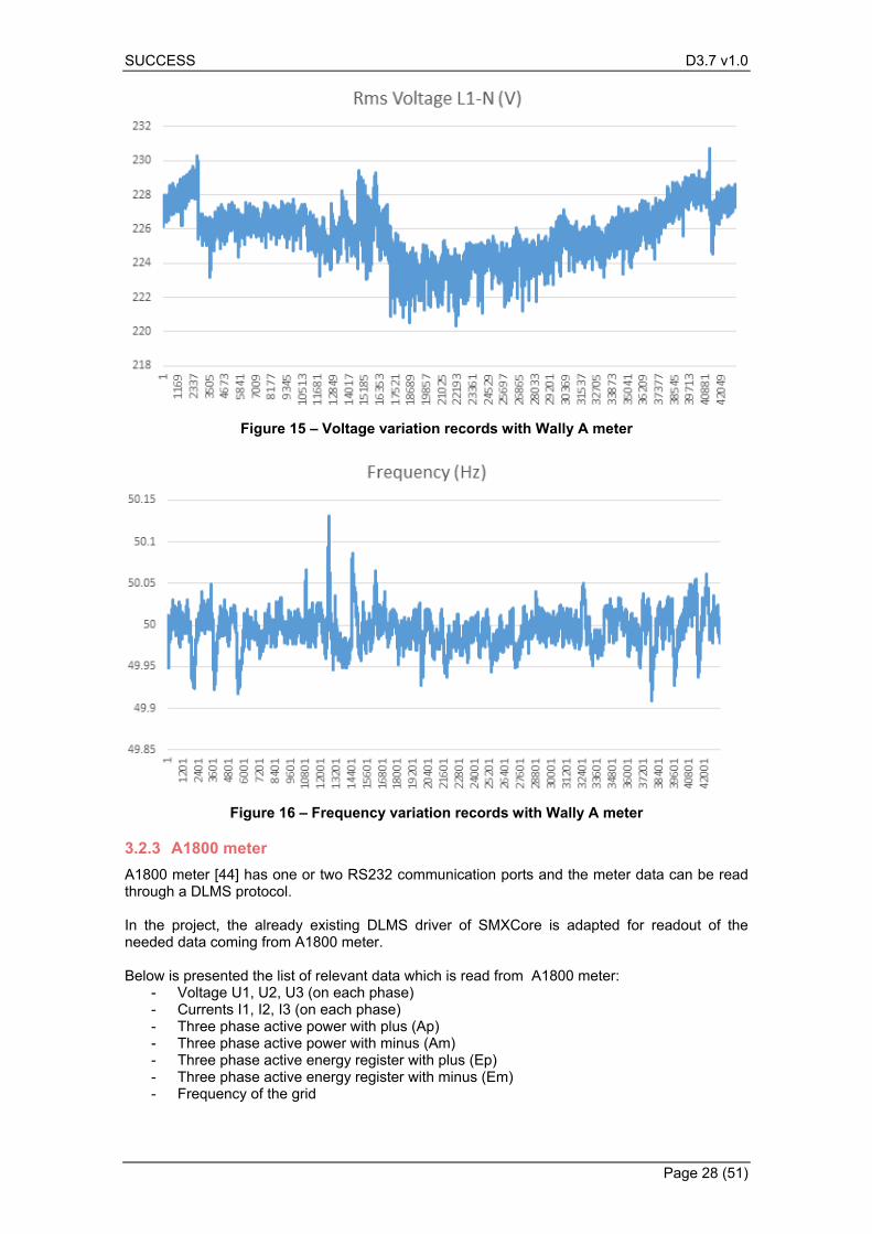
Examples of voltage and frequency variation are presented in the figures 15 and 16 below
SUCCESS D3.7 v1.0
Page 28 (51)
Figure 15 – Voltage variation records with Wally A meter
Figure 16 – Frequency variation records with Wally A meter
A1800 meter 3.2.3
A1800 meter [44] has one or two RS232 communication ports and the meter data can be read through a DLMS protocol. In the project, the already existing DLMS driver of SMXCore is adapted for readout of the needed data coming from A1800 meter. Below is presented the list of relevant data which is read from A1800 meter:
- Voltage U1, U2, U3 (on each phase) - Currents I1, I2, I3 (on each phase) - Three phase active power with plus (Ap) - Three phase active power with minus (Am) - Three phase active energy register with plus (Ep) - Three phase active energy register with minus (Em) - Frequency of the grid
SUCCESS D3.7 v1.0
Page 29 (51)
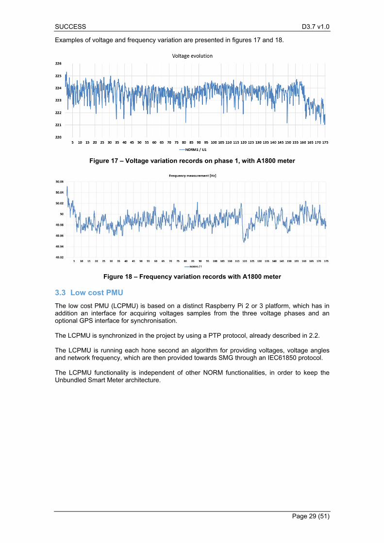
Examples of voltage and frequency variation are presented in figures 17 and 18.
Figure 17 – Voltage variation records on phase 1, with A1800 meter
Figure 18 – Frequency variation records with A1800 meter
Low cost PMU 3.3
The low cost PMU (LCPMU) is based on a distinct Raspberry Pi 2 or 3 platform, which has in addition an interface for acquiring voltages samples from the three voltage phases and an optional GPS interface for synchronisation. The LCPMU is synchronized in the project by using a PTP protocol, already described in 2.2. The LCPMU is running each hone second an algorithm for providing voltages, voltage angles and network frequency, which are then provided towards SMG through an IEC61850 protocol. The LCPMU functionality is independent of other NORM functionalities, in order to keep the Unbundled Smart Meter architecture.
SUCCESS D3.7 v1.0
Page 30 (51)
4. NORM Smart Meter Gateway software
Taking into account what is written in chapter 2, the consortium will adopt the following steps to achieve the goal of testing and integrating the SUCCESS Security Monitoring Solution. In this course, first, individual component testing on all SUCCESS Security Monitoring Solution will be sought. The first rounds of testing will refer to components developed in the context of WP3, followed by WP4 components tested and documented in the context of D4.7.
Open source SMXCore 4.1
4.1.1.1 Real-time Database organisation
From dynamics and persistency point of view, SMXCore considers two types of data: A) Real-time data, which is non-persistent and which is expected to be frequently modified (e.g. each 1 second). Examples of such data are the instrumentation data coming from the meter, such as active and reactive power (P and Q), voltages U and currents I. This data are kept as variables in the SMXCore program (RAM allocated variables) and can be quickly accessed internally or outside SMXCore. This data is obtained by applications (Apps) through frequent read or write by using an MQTT mechanism which is supported by SMXCore, which can incorporate instances of MQTT clients (to be described later, in the SMXCore modules). Real-time data are not saved on disk, thus after a shut-down / power-up it is needed new data to be written in the SMXCore variables, in order to have again real data in the allocated variables. B) Archive data. This is persistent data, with storage not based on a database, but on daily logs of files, which have records every 1 to 3600 seconds (programmable).
4.1.1.2 RBAC concept
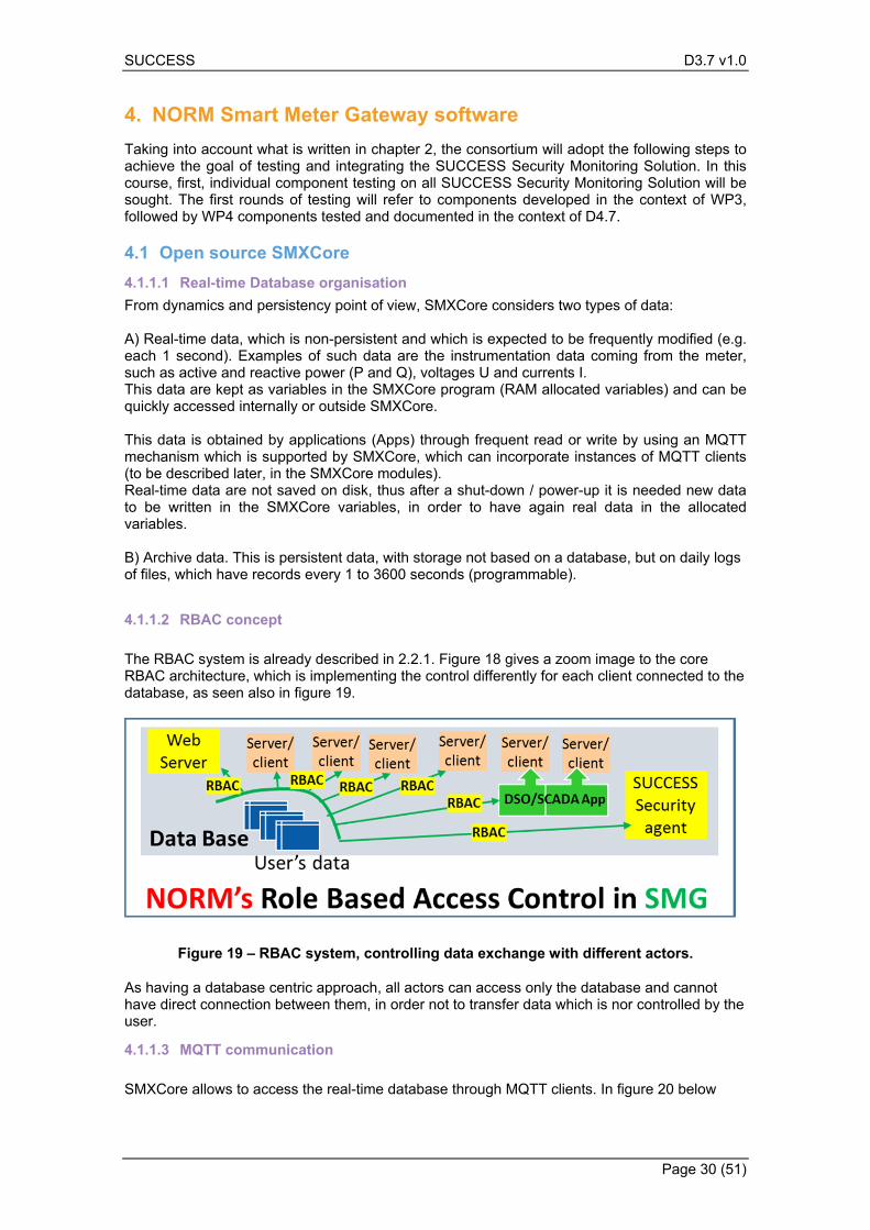
The RBAC system is already described in 2.2.1. Figure 18 gives a zoom image to the core RBAC architecture, which is implementing the control differently for each client connected to the database, as seen also in figure 19.
Figure 19 – RBAC system, controlling data exchange with different actors.
As having a database centric approach, all actors can access only the database and cannot have direct connection between them, in order not to transfer data which is nor controlled by the user.
4.1.1.3 MQTT communication
SMXCore allows to access the real-time database through MQTT clients. In figure 20 below
SUCCESS D3.7 v1.0
Page 31 (51)
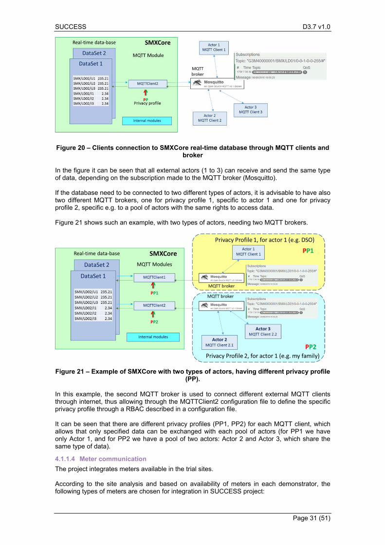
Figure 20 – Clients connection to SMXCore real-time database through MQTT clients and broker
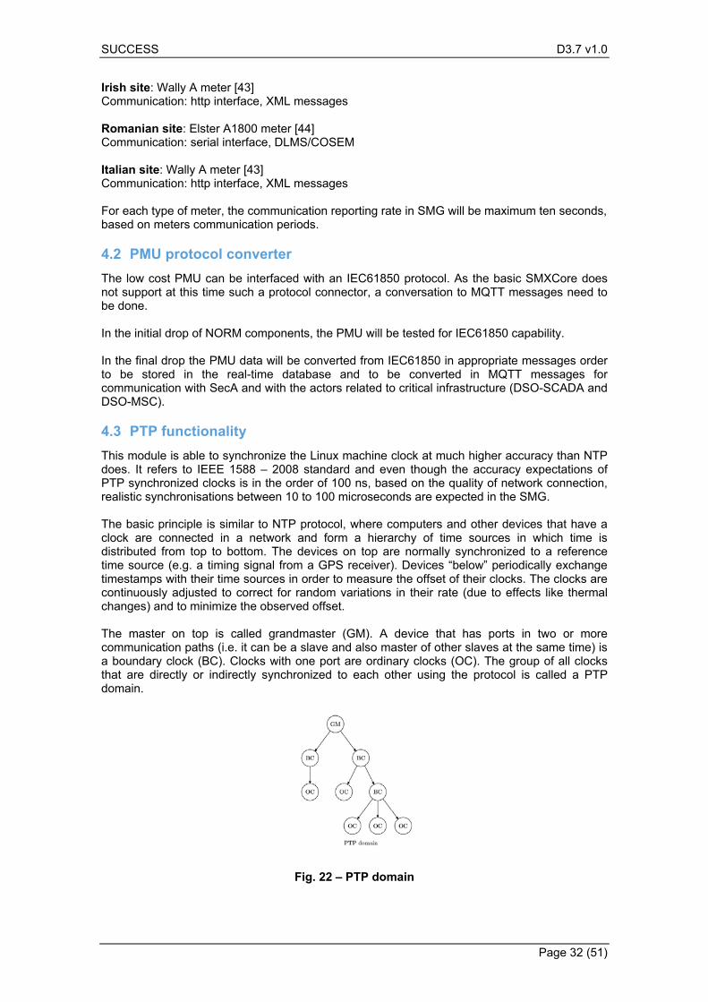
In the figure it can be seen that all external actors (1 to 3) can receive and send the same type of data, depending on the subscription made to the MQTT broker (Mosquitto). If the database need to be connected to two different types of actors, it is advisable to have also two different MQTT brokers, one for privacy profile 1, specific to actor 1 and one for privacy profile 2, specific e.g. to a pool of actors with the same rights to access data. Figure 21 shows such an example, with two types of actors, needing two MQTT brokers.
Figure 21 – Example of SMXCore with two types of actors, having different privacy profile (PP).
In this example, the second MQTT broker is used to connect different external MQTT clients through internet, thus allowing through the MQTTClient2 configuration file to define the specific privacy profile through a RBAC described in a configuration file. It can be seen that there are different privacy profiles (PP1, PP2) for each MQTT client, which allows that only specified data can be exchanged with each pool of actors (for PP1 we have only Actor 1, and for PP2 we have a pool of two actors: Actor 2 and Actor 3, which share the same type of data).
4.1.1.4 Meter communication
The project integrates meters available in the trial sites. According to the site analysis and based on availability of meters in each demonstrator, the following types of meters are chosen for integration in SUCCESS project:
SUCCESS D3.7 v1.0
Page 32 (51)
Irish site: Wally A meter [43] Communication: http interface, XML messages Romanian site: Elster A1800 meter [44] Communication: serial interface, DLMS/COSEM Italian site: Wally A meter [43] Communication: http interface, XML messages For each type of meter, the communication reporting rate in SMG will be maximum ten seconds, based on meters communication periods.
PMU protocol converter 4.2
The low cost PMU can be interfaced with an IEC61850 protocol. As the basic SMXCore does not support at this time such a protocol connector, a conversation to MQTT messages need to be done. In the initial drop of NORM components, the PMU will be tested for IEC61850 capability. In the final drop the PMU data will be converted from IEC61850 in appropriate messages order to be stored in the real-time database and to be converted in MQTT messages for communication with SecA and with the actors related to critical infrastructure (DSO-SCADA and DSO-MSC).
PTP functionality 4.3
This module is able to synchronize the Linux machine clock at much higher accuracy than NTP does. It refers to IEEE 1588 – 2008 standard and even though the accuracy expectations of PTP synchronized clocks is in the order of 100 ns, based on the quality of network connection, realistic synchronisations between 10 to 100 microseconds are expected in the SMG. The basic principle is similar to NTP protocol, where computers and other devices that have a clock are connected in a network and form a hierarchy of time sources in which time is distributed from top to bottom. The devices on top are normally synchronized to a reference time source (e.g. a timing signal from a GPS receiver). Devices “below” periodically exchange timestamps with their time sources in order to measure the offset of their clocks. The clocks are continuously adjusted to correct for random variations in their rate (due to effects like thermal changes) and to minimize the observed offset. The master on top is called grandmaster (GM). A device that has ports in two or more communication paths (i.e. it can be a slave and also master of other slaves at the same time) is a boundary clock (BC). Clocks with one port are ordinary clocks (OC). The group of all clocks that are directly or indirectly synchronized to each other using the protocol is called a PTP domain.
Fig. 22 – PTP domain
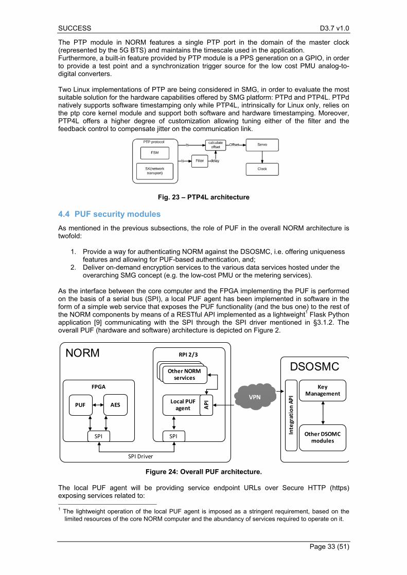
SUCCESS D3.7 v1.0
Page 33 (51)
The PTP module in NORM features a single PTP port in the domain of the master clock (represented by the 5G BTS) and maintains the timescale used in the application. Furthermore, a built-in feature provided by PTP module is a PPS generation on a GPIO, in order to provide a test point and a synchronization trigger source for the low cost PMU analog-to-digital converters. Two Linux implementations of PTP are being considered in SMG, in order to evaluate the most suitable solution for the hardware capabilities offered by SMG platform: PTPd and PTP4L. PTPd natively supports software timestamping only while PTP4L, intrinsically for Linux only, relies on the ptp core kernel module and support both software and hardware timestamping. Moreover, PTP4L offers a higher degree of customization allowing tuning either of the filter and the feedback control to compensate jitter on the communication link.
Fig. 23 – PTP4L architecture
PUF security modules 4.4
As mentioned in the previous subsections, the role of PUF in the overall NORM architecture is twofold:
1. Provide a way for authenticating NORM against the DSOSMC, i.e. offering uniqueness features and allowing for PUF-based authentication, and;
2. Deliver on-demand encryption services to the various data services hosted under the overarching SMG concept (e.g. the low-cost PMU or the metering services).
As the interface between the core computer and the FPGA implementing the PUF is performed on the basis of a serial bus (SPI), a local PUF agent has been implemented in software in the form of a simple web service that exposes the PUF functionality (and the bus one) to the rest of the NORM components by means of a RESTful API implemented as a lightweight1 Flask Python application [9] communicating with the SPI through the SPI driver mentioned in §3.1.2. The overall PUF (hardware and software) architecture is depicted on Figure 2.
Figure 24: Overall PUF architecture.
The local PUF agent will be providing service endpoint URLs over Secure HTTP (https) exposing services related to: 1 The lightweight operation of the local PUF agent is imposed as a stringent requirement, based on the
limited resources of the core NORM computer and the abundancy of services required to operate on it.
NORM
FPGA
RPI 2/3
DSOSMC
VPNLocal PUF agent
SPI
API
SPI
Key Management
Other DSOMC modules
Integration API
SPI Driver
Other NORM services
Other NORM servicesOther NORM
services
PUF AES
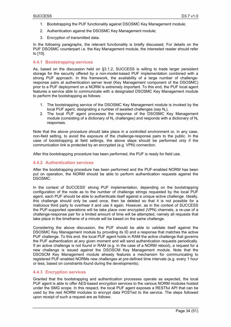
SUCCESS D3.7 v1.0
Page 34 (51)
1. Bootstrapping the PUF functionality against DSOSMC Key Management module;
2. Authentication against the DSOSMC Key Management module;
3. Encryption of transmitted data.
In the following paragraphs, the relevant functionality is briefly discussed. For details on the PUF DSOSMC counterpart i.e. the Key Management module, the interested reader should refer to [10].
Bootstrapping services 4.4.1
As, based on the discussion held on §3.1.2, SUCCESS is willing to trade larger persistent storage for the security offered by a non-model-based PUF implementation combined with a strong PUF approach. In this framework, the availability of a large number of challenge-response pairs at authentication server level (Key Management component of the DSOSMC) prior to a PUF deployment on a NORM is extremely important. To this end, the PUF local agent features a service able to communicate with a designated DSOSMC Key Management module to perform the bootstrapping as follows:
1. The bootstrapping service of the DSOSMC Key Management module is invoked by the local PUF agent, designating a number of awaited challenges (say Nc),
2. The local PUF agent processes the response of the DSOSMC Key Management module (consisting of a dictionary of Nc challenges) and responds with a dictionary of Nc responses.
Note that the above procedure should take place in a controlled environment or, in any case, non-field setting, to avoid the exposure of the challenge-response pairs to the public. In the case of bootstrapping at field settings, the above steps should be performed only if the communication link is protected by an encrypted (e.g. VPN) connection. After this bootstrapping procedure has been performed, the PUF is ready for field use.
Authentication services 4.4.2
After the bootstrapping procedure has been performed and the PUF-enabled NORM has been put on operation, the NORM should be able to perform authentication requests against the DSOSMC. In the context of SUCCESS’ strong PUF implementation, depending on the bootstrapping configuration of the node as to the number of challenge strings requested by the local PUF agent, each PUF should be able to authenticate itself against a unique active challenge. Ideally, this challenge should only be used once, then be deleted so that it is not possible for a malicious third party to overhear it and use it again. However, as in the context of SUCCESS the PUF-supported operations will be take place over encrypted (VPN) channels, a re-use of a challenge-response pair for a limited amount of time will be attempted, namely all requests that take place in the timeframe of a minute will be based on the same challenge. Considering the above discussion, the PUF should be able to validate itself against the DSOSMC Key Management module by providing its ID and a response that matches the active PUF challenge. To this end, the local PUF agent holds in RAM the active challenge that governs the PUF authentication at any given moment and will send authentication requests periodically. If an active challenge is not found in RAM (e.g. in the case of a NORM reboot), a request for a new challenge is issued against the DSOSCM Key Management module. Note that the DSOSCM Key Management module already features a mechanism for communicating to registered PUF-enabled NORMs new challenges at pre-defined time intervals (e.g. every 1 hour or less, based on constraints found during the developments).
Encryption services 4.4.3
Granted that the bootstrapping and authentication processes operate as expected, the local PUF agent is able to offer AES-based encryption services to the various NORM modules hosted under the SMG scope. In this respect, the local PUF agent exposes a RESTful API that can be used by the rest NORM modules to encrypt data POSTed to the service. The steps followed upon receipt of such a request are as follows:
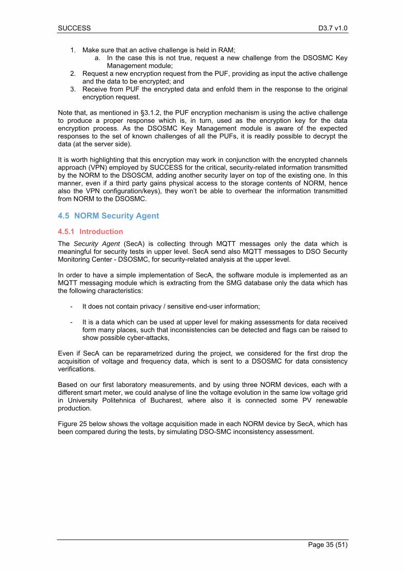
SUCCESS D3.7 v1.0
Page 35 (51)
1. Make sure that an active challenge is held in RAM;
a. In the case this is not true, request a new challenge from the DSOSMC Key Management module;
2. Request a new encryption request from the PUF, providing as input the active challenge and the data to be encrypted; and
3. Receive from PUF the encrypted data and enfold them in the response to the original encryption request.
Note that, as mentioned in §3.1.2, the PUF encryption mechanism is using the active challenge to produce a proper response which is, in turn, used as the encryption key for the data encryption process. As the DSOSMC Key Management module is aware of the expected responses to the set of known challenges of all the PUFs, it is readily possible to decrypt the data (at the server side). It is worth highlighting that this encryption may work in conjunction with the encrypted channels approach (VPN) employed by SUCCESS for the critical, security-related information transmitted by the NORM to the DSOSCM, adding another security layer on top of the existing one. In this manner, even if a third party gains physical access to the storage contents of NORM, hence also the VPN configuration/keys), they won’t be able to overhear the information transmitted from NORM to the DSOSMC.
NORM Security Agent 4.5
Introduction 4.5.1
The Security Agent (SecA) is collecting through MQTT messages only the data which is meaningful for security tests in upper level. SecA send also MQTT messages to DSO Security Monitoring Center - DSOSMC, for security-related analysis at the upper level. In order to have a simple implementation of SecA, the software module is implemented as an MQTT messaging module which is extracting from the SMG database only the data which has the following characteristics:
- It does not contain privacy / sensitive end-user information;
- It is a data which can be used at upper level for making assessments for data received form many places, such that inconsistencies can be detected and flags can be raised to show possible cyber-attacks,
Even if SecA can be reparametrized during the project, we considered for the first drop the acquisition of voltage and frequency data, which is sent to a DSOSMC for data consistency verifications. Based on our first laboratory measurements, and by using three NORM devices, each with a different smart meter, we could analyse of line the voltage evolution in the same low voltage grid in University Politehnica of Bucharest, where also it is connected some PV renewable production. Figure 25 below shows the voltage acquisition made in each NORM device by SecA, which has been compared during the tests, by simulating DSO-SMC inconsistency assessment.
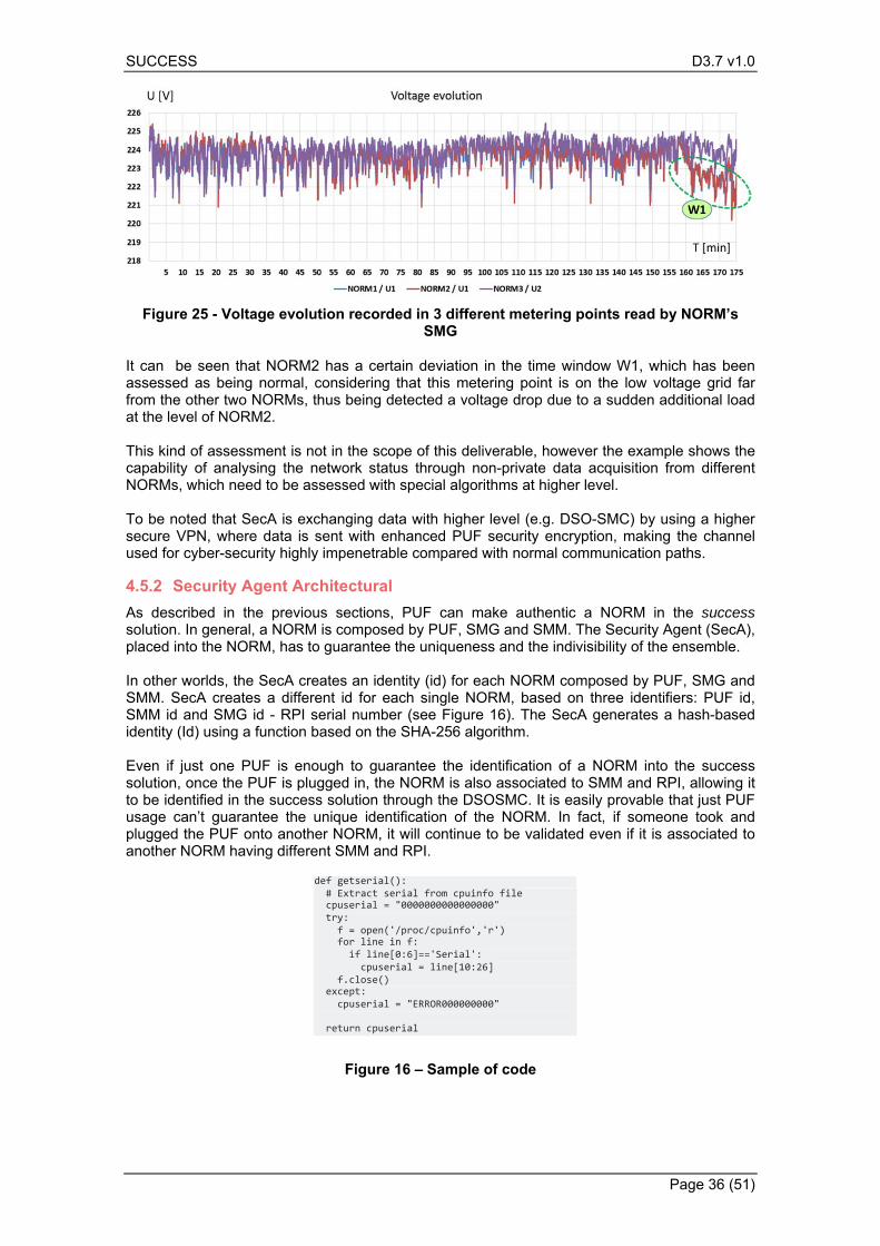
SUCCESS D3.7 v1.0
Page 36 (51)
Figure 25 - Voltage evolution recorded in 3 different metering points read by NORM’s SMG
It can be seen that NORM2 has a certain deviation in the time window W1, which has been assessed as being normal, considering that this metering point is on the low voltage grid far from the other two NORMs, thus being detected a voltage drop due to a sudden additional load at the level of NORM2. This kind of assessment is not in the scope of this deliverable, however the example shows the capability of analysing the network status through non-private data acquisition from different NORMs, which need to be assessed with special algorithms at higher level. To be noted that SecA is exchanging data with higher level (e.g. DSO-SMC) by using a higher secure VPN, where data is sent with enhanced PUF security encryption, making the channel used for cyber-security highly impenetrable compared with normal communication paths.
Security Agent Architectural 4.5.2
As described in the previous sections, PUF can make authentic a NORM in the success solution. In general, a NORM is composed by PUF, SMG and SMM. The Security Agent (SecA), placed into the NORM, has to guarantee the uniqueness and the indivisibility of the ensemble. In other worlds, the SecA creates an identity (id) for each NORM composed by PUF, SMG and SMM. SecA creates a different id for each single NORM, based on three identifiers: PUF id, SMM id and SMG id - RPI serial number (see Figure 16). The SecA generates a hash-based identity (Id) using a function based on the SHA-256 algorithm. Even if just one PUF is enough to guarantee the identification of a NORM into the success solution, once the PUF is plugged in, the NORM is also associated to SMM and RPI, allowing it to be identified in the success solution through the DSOSMC. It is easily provable that just PUF usage can’t guarantee the unique identification of the NORM. In fact, if someone took and plugged the PUF onto another NORM, it will continue to be validated even if it is associated to another NORM having different SMM and RPI.
def getserial(): # Extract serial from cpuinfo file cpuserial = "0000000000000000" try: f = open('/proc/cpuinfo','r') for line in f: if line[0:6]=='Serial': cpuserial = line[10:26] f.close() except: cpuserial = "ERROR000000000" return cpuserial
Figure 16 – Sample of code
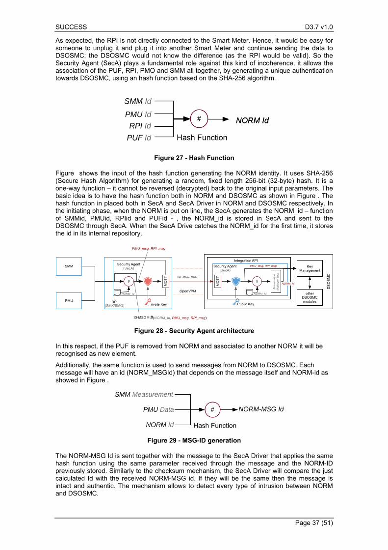
SUCCESS D3.7 v1.0
Page 37 (51)
As expected, the RPI is not directly connected to the Smart Meter. Hence, it would be easy for someone to unplug it and plug it into another Smart Meter and continue sending the data to DSOSMC; the DSOSMC would not know the difference (as the RPI would be valid). So the Security Agent (SecA) plays a fundamental role against this kind of incoherence, it allows the association of the PUF, RPI, PMO and SMM all together, by generating a unique authentication towards DSOSMC, using an hash function based on the SHA-256 algorithm.
Figure 27 - Hash Function
Figure shows the input of the hash function generating the NORM identity. It uses SHA-256 (Secure Hash Algorithm) for generating a random, fixed length 256-bit (32-byte) hash. It is a one-way function – it cannot be reversed (decrypted) back to the original input parameters. The basic idea is to have the hash function both in NORM and DSOSMC as shown in Figure . The hash function in placed both in SecA and SecA Driver in NORM and DSOSMC respectively. In the initiating phase, when the NORM is put on line, the SecA generates the NORM_id – function of SMMid, PMUid, RPIid and PUFid - , the NORM_id is stored in SecA and sent to the DSOSMC through SecA. When the SecA Drive catches the NORM_id for the first time, it stores the id in its internal repository.
Figure 28 - Security Agent architecture
In this respect, if the PUF is removed from NORM and associated to another NORM it will be recognised as new element.
Additionally, the same function is used to send messages from NORM to DSOSMC. Each message will have an id (NORM_MSGId) that depends on the message itself and NORM-id as showed in Figure .
Figure 29 - MSG-ID generation
The NORM-MSG Id is sent together with the message to the SecA Driver that applies the same hash function using the same parameter received through the message and the NORM-ID previously stored. Similarly to the checksum mechanism, the SecA Driver will compare the just calculated Id with the received NORM-MSG id. If they will be the same then the message is intact and authentic. The mechanism allows to detect every type of intrusion between NORM and DSOSMC.
RPI Id#
Hash Function
NORM IdNORM Id
SMM Id
PMU Id
PUF Id
SMM
PMU RPI(SMX/SMG)
Security Agent(SecA)
#
#(NORM_Id, PMU_msg, RPI_msg)
OpenVPM
ID-MSG
MQ
TT
=
(ID_MSG, MSG)
MQ
TT
#
Security Agent(SecA)
Private Key
Pro
ven
anc
eM
an
age
r To
ol
Key Management
other DSOSMC modules
PMU_msg, RPI_msg
NORM_Id
DS
OS
MC
NORM_Id
PMU_msg, RPI_msg
Integration API
Public Key
NORM_Id
#
Hash Function
SMM Measurement
PMU Data
NORM Id
NORM-MSG Id
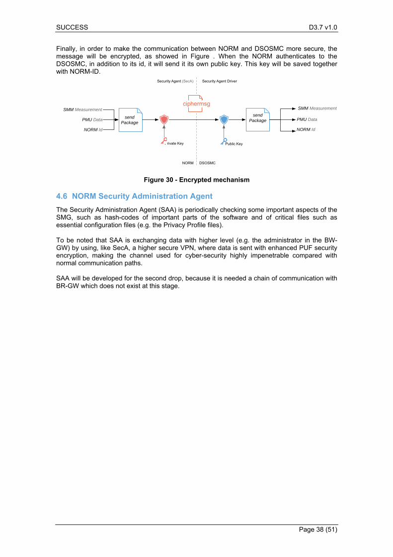
SUCCESS D3.7 v1.0
Page 38 (51)
Finally, in order to make the communication between NORM and DSOSMC more secure, the message will be encrypted, as showed in Figure . When the NORM authenticates to the DSOSMC, in addition to its id, it will send it its own public key. This key will be saved together with NORM-ID.
Figure 30 - Encrypted mechanism
NORM Security Administration Agent 4.6
The Security Administration Agent (SAA) is periodically checking some important aspects of the SMG, such as hash-codes of important parts of the software and of critical files such as essential configuration files (e.g. the Privacy Profile files). To be noted that SAA is exchanging data with higher level (e.g. the administrator in the BW-GW) by using, like SecA, a higher secure VPN, where data is sent with enhanced PUF security encryption, making the channel used for cyber-security highly impenetrable compared with normal communication paths. SAA will be developed for the second drop, because it is needed a chain of communication with BR-GW which does not exist at this stage.
Security Agent (SecA) Security Agent Driver
NORM DSOSMC
Private Key Public Key
SMM Measurement
PMU Data
NORM Id
send Package
SMM Measurement
PMU Data
NORM Id
send Package
ciphermsg
SUCCESS D3.7 v1.0
Page 39 (51)
5. Test plan for individual components
The goal of this section is to provide a preliminary strategy and plan that will be followed in the realization of the individual single component testing the belong to WP3, namely NORM and the DSO-SMC. To that end, we:
• introduce a common formalization list of terms for the well-defined definition of tests. • Brief introduction about protocols that will be used between D-SMC and NORM • define the typology of features that will be tested during the individual test phase. • define a preliminary plan describing test of NORM and D-SMC.
Individual module testing refers to the testing of the individual system components with respect to the requirements. After all modules are verified, then the integration will begin and when it is completed, a final set of tests will be performed.
BASIC SMG software 5.1
BASIC SMG software refers to the following main components: - The SMXCore, which is the basic software around which all applications are running. It
contains: o the realtime database o software connectors to external actors, based on MQTT messages; the
connectors have an internal RBAC system which allows that only selected dat can be sent or received from a specific agent
o drivers for energy meters, acting as Smart metrology meters; o other internal functions
- The Security Agent, which is one of the agents, acting as data extractor for the upper levels, such as DSO-SMG
- Driver for PMU integration - Software for classic OpenVPN connectivity - Software for the PUF security mechanism needed on NORM side
Security Agent 5.2
Security agent package will be tested by parametrising the MQTT client to send voltage and frequency data at a certain time interval. The following tests will be made:
- The SecA data is arriving to a DSOSMC simulated module This test will show the availability of SecA to provide necessary data to upper level of security monitoring center
- Any attempt from DSOSMC for obtaining other data (by subscribing to the Mosquitto broker) will be un-successful This test will show that private data is well kept and cannot be obtained with un-authorised requests.
PUF functionality 5.3
The PUF-enabled hardware security features will be tested on both hardware and software (local PUF agent) in combination with the DSOSMC Key Management module as to its capabilities to:
Test the bootstrapping and challenge-response pairs updating of PUF; Test the ability of PUF to implement NORM authentication/authorization against the
DSOSMC Key Management module, effectively offering uniqueness characteristics on the NORM identification processes;
Deliver encryption/decryption services to the rest of the NORM services.
SUCCESS D3.7 v1.0
Page 40 (51)
The tests will be carried out on non-production environments and will ensure that the hardware security features of the NORM are robust, fulfilling the strict security requirements of NORM.
PTP synchronisation 5.4
PTP synchronisation will be tested against a counter-machine which is able to provide a GPS time synchronisation. As the level of time accuracy is at microseconds level or less, the following simple test schema will be used: the counter-machine (basically a GPS receiver with antenna) shall be equipped with PPS
output; the PPS output generated by SMG is compared by mean of a digital oscilloscope with the
reference PPS output of counter-machine: the measured delta time and jitter between the two signals under all circumstances shall be limited within the maximum tolerance allowed by low cost PMU constraints.
Other standard console utilities (PMC, phc2sys) are used to assess the operation of the PTP synchronisation at user level.
Low cost PMU 5.5
Low cost PMU (LCPMU) will be tested for its basic functionality. In this respect, it will be tested that LCPMU is providing at reporting rates of one second the voltage levels and the voltage angles as well as the value of the network frequency. Voltage levels and frequency will be compared with the data recorded by SMG from meters and/or with the measurements from laboratory devices. For this it will be used in the first drop of components a specific software for testing LCPMU alone, and in the second drop it will be tested integrated in SMG, meaning with data integrated in the SecA publish-subscribe mechanism.
EMC test for PUF 5.6
EMC will be tested and evaluated according to the CISPR 1270_INF guidance for equipment connected to smart grids. Specifically, SMG can be treated as a data concentrator device, whose reference standards are the following:
- EN61000-6-2 – Immunity for industrial environment - EN61000-6-4– Emission for industrial environment - EN60950-1 IT Equipment – Safety (Cat IV 300 V, reinforced insulation, pollution degree
2). With specific reference to EMC test for PUF, the following three ports of SMG can be considered:
1. Enclosure port 2. Primary AC power supply input 3. Wired network port (cable length < 10m)
Moreover, the proper acceptance criterion to consider is A, which means that the device shall continue to operate as required during and after the test and no performance degradation below the indicated level is allowed. Consequently, the following table resumes the EMC test to apply for EMC PUF immunity conformance:
Table 4 – EMC tests
Immunity test Reference
Standard Test Limit Notes Port
Acceptance
Criterion
Power frequency IEC 61000-4-8 30A/m Orientation on Port 1 A
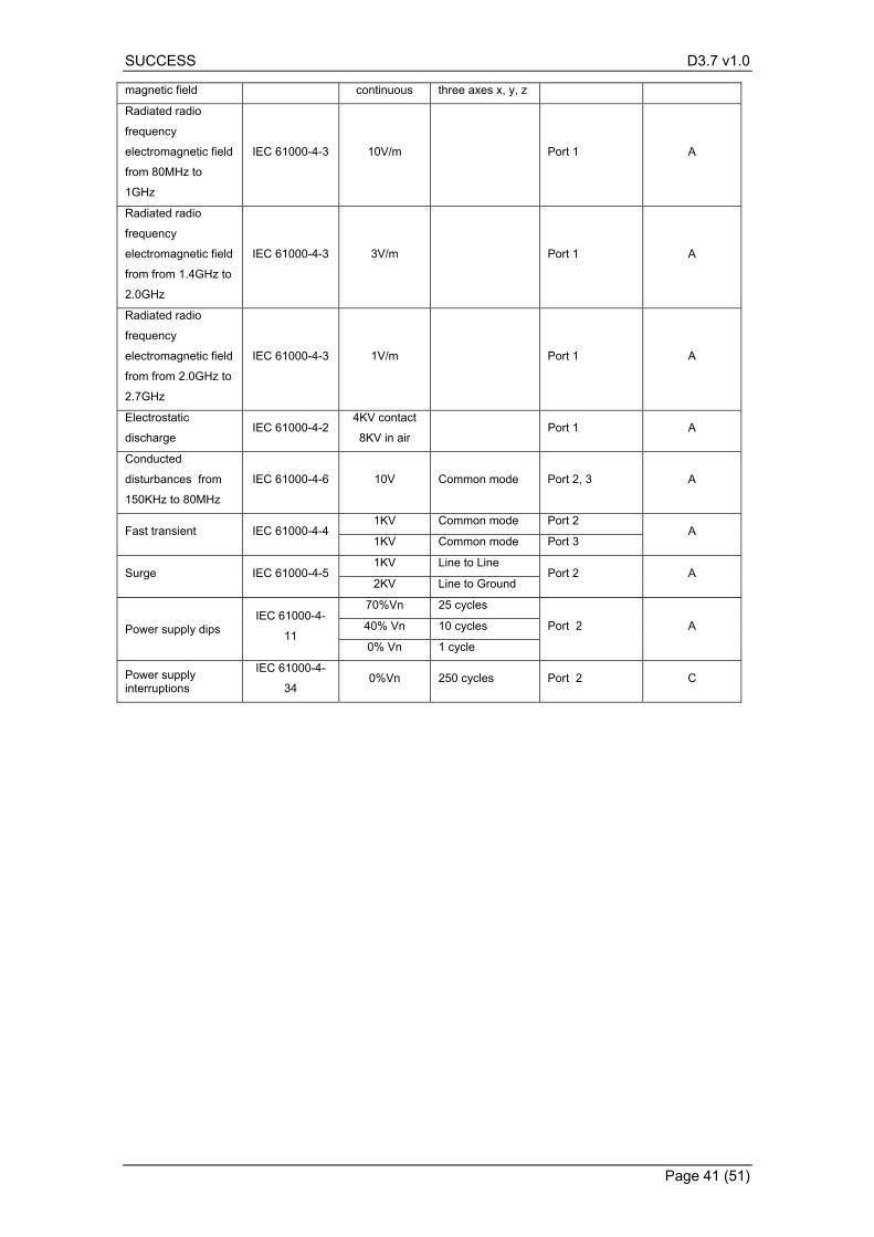
SUCCESS D3.7 v1.0
Page 41 (51)
magnetic field continuous three axes x, y, z
Radiated radio
frequency
electromagnetic field
from 80MHz to
1GHz
IEC 61000-4-3 10V/m Port 1 A
Radiated radio
frequency
electromagnetic field
from from 1.4GHz to
2.0GHz
IEC 61000-4-3 3V/m Port 1 A
Radiated radio
frequency
electromagnetic field
from from 2.0GHz to
2.7GHz
IEC 61000-4-3 1V/m Port 1 A
Electrostatic
discharge IEC 61000-4-2
4KV contact
8KV in air Port 1 A
Conducted
disturbances from
150KHz to 80MHz
IEC 61000-4-6 10V Common mode Port 2, 3 A
Fast transient IEC 61000-4-4 1KV Common mode Port 2
A 1KV Common mode Port 3
Surge IEC 61000-4-5 1KV Line to Line
Port 2 A 2KV Line to Ground
Power supply dips IEC 61000-4-
11
70%Vn 25 cycles
Port 2 A 40% Vn 10 cycles
0% Vn 1 cycle
Power supply interruptions
IEC 61000-4-
34 0%Vn 250 cycles Port 2 C
SUCCESS D3.7 v1.0
Page 42 (51)
6. References
[1] M. Sănduleac, M. Eremia, L. Toma, P. Borza, "Integrating the Electrical Vehicles in the
Smart Grid through Unbundled Smart Metering and multi-objective Virtual Power Plants", 2011 2nd IEEE PES ISGT Europe, Manchester, December 2011
[2] C. Herder, M.-D. Yu, F. Koushanfar and S. Devadas, “Physical Unclonable Functions and Applications: A Tutorial,” in Proceedings of the IEEE, 2014.
[3] Xilinx, “Spartan-6 FPGA Family,” Xilinx, [Online]. Available: https://www.xilinx.com/support/documentation/selection-guides/cost-optimized-product-selection-guide.pdf#S6. [Accessed Mar. 2017].
[4] Raspbian, “Welcome page,” [Online]. Available: https://www.raspbian.org. [Accessed Mar. 2017].
[5] C. Gu, J. P. Murphy and M. O'Niell, “A unique and robust single slice FPGA identification generator,” in IEEE International Symposium on Circuits and Systems, Melbourne, Victoria, Australia, 2014.
[6] S. S. Kumar, J. Guajardo, R. Maes, G. J. Schrijen and P. Tuyls, “The butterfly PUF: protecting IP on every FPGA,” in IEEE International Workshop on Hardware-Oriented Security and Trust, Anaheim, CA, USA, 2008.
[7] S. Tajik, E. Dietz, S. Frohmann, J.-P. Seifert, D. Nedospasov, C. Helfmeier, C. Boit and H. Dittrich, “Physical characterization of Arbiter PUFs,” in 16th International Workshop on Cryptographic Hardware and Embedded Systems, New York, 2014.
[8] G. E. Suh and S. Devadas, “Physical unclonable functions for device authentication and secret key generation,” in Proceedings of the 44th annual Design Automation Conference, 2007.
[9] Flask, “Welcome page,” [Online]. Available: http://flask.pocoo.org. [Accessed Mar. 2017].
[10] SUCCESS, “Deliverable D3.4: Information Security Management Components and Documentation V1.0,” 2017.
[11] D. Spinellis, “15 Rules for Writing Quality Code,” 9 06 2014. [Online]. Available: http://www.informit.com/articles/article.aspx?p=2223710. [Accessed 17 09 2014].
[12] C. Alexander, S. Ishikawa, M. Silverstein, M. Jacobson, I. Fiksdahl-King and S. Angel, A Pattern Language, Towns, Buildings, Construction, New York: Oxford University Press, 1977.
[13] “Cloud Patterns,” [Online]. Available: http://cloudpatterns.org/. [Accessed Jan. 2017].
[14] “Big Data Patterns,” [Online]. Available: http://www.bigdatapatterns.org/. [Accessed Jan. 2017].
[15] SUCCESS, “Deliverable D3.4: Information Security Management Components and Documentation v1,” 2017.
[16] FIWARE, “Cygnus,” [Online]. Available: https://github.com/telefonicaid/fiware-cygnus. [Accessed Jan 2017].
[17] Wikipedia. [Online]. Available: https://en.wikipedia.org/wiki/Software_test_documentation. [Accessed 10 January 2017].
[18] “. 2. S. T. The International Software Testing Standard. [Online]. Available: http://www.softwaretestingstandard.org/. . [Accessed 10 September 2014].
[19] NOBEL GRID project, www.nobelgrid.eu
[20] NOBEL GRID, “D1.1-Distribution grid and retail market requirements definition,” 2015.
[21] NOBEL GRID, “D1.2-Distribution grid and retial market scenarios and use cases definition,” 2015.
[22] European Union, “DIRECTIVE 2014/32/EU OF THE EUROPEAN PARLIAMENT AND OF THE COUNCIL of 26 February 2014 on the harmonisation of the laws of the Member States relating to the making available on the market of measuring instruments (recast),” Offical Journal of the European Union, 2014.
[23] Smart Grid Task Force - Expert Group 3 (EG3) - Regulatory Recommendations for Smart Grids Deployment, First Year Report: Options on handling Smart Grids Data, January 2013
SUCCESS D3.7 v1.0
Page 43 (51)
[24] SUCCESS, “Deliverable D3.7 : Next Generation Smart Meter V1,” 2017.
[25] SUCCESS, “Deliverable D3.11: Integration and Validation Plan. Test and certification specifications v2,” 2017.
[26] SUCCESS, “Deliverable 3.12 : Integration and Validation Plan. Test and certification specifications v3,” 2018.
[27] SUCCESS, “Deliverable D4.8 : Integration and Validation Plan. Test and certification specifications v2,” 2017.
[28] SUCCESS, “Deliverable 4.9 : Integration and Validation Plan. Test and certification specifications v3,” 2018.
[29] M. J. a. M. L. S. Harrold, “An incremental approach to unit testing during maintenance.,” Software Maintenance,, 1988.
[30] K. Beck, Test-driven development: by example, Addison-Wesley Professional, 2003.
[31] T. Ostrand, White‐Box Testing, Encyclopedia of Software Engineering, 2002.
[32] B. Beizer, Black-box testing: techniques for functional testing of software and systems., John Wiley & Sons, Inc., 1985.
[33] M. E. a. F. K. Khan, “A comparative study of white box, black box and grey box testing techniques.,” International Journal of Advanced Computer Science and Applications (IJACSA), 2012.
[34] H. K. a. L. W. Leung, “A study of integration testing and software regression at the integration level.,” Software Maintenance, 1990, Proceedings., Conference on.IEEE, 1990.
[35] “Protection of personal data,” [Online]. Available: http://ec.europa.eu/justice/data-protection/.
[36] “REGULATION (EU) 2016/679 OF THE EUROPEAN PARLIAMENT AND OF THE COUNCIL,” [Online]. Available: http://eur-lex.europa.eu/legal-content/EN/TXT/?uri=CELEX%3A32016R0679.
[37] IEC, “62056-6-2:2013,” 201. [Online]. Available: https://webstore.iec.ch/publication/6410. [Accessed 20 12 2016].
[38] N. a. B. J. C. Saxena, “State of the art authentication, access control, and secure integration in smart grid,” Energies, 2015.
[39] S. Feuerhahn, M. Zillgith, C. Wittwer and C. Wietfeld, “Comparison of the communication protocols DLMS/COSEM SML IEC 61850 for smart metering applications,” in Smart Grid Communications (SmartGridComm), 2011 IEEE International Conference on. IEEE, Bruxelles.
[40] “ OpenADR and Cyber Security,” [Online]. Available: http://www.openadr.org/cyber-security. [Accessed 20 12 2016].
[41] SUCCESS, “Deliverable D4.4: Description of available components for SW functions, infrastructure and related documentation v1,” 2017.
[42] Dr. Helge Kreutzmann, M.Sc. Stefan Vollmer. Protection Profile for the Gateway of a Smart Metering System (Smart Meter Gateway PP), v 1.3. s.l. : Federal Office for Information Security, 2014. BSI-CC-PP-0073
[43] TW-TeamWare WallyA3, http://www.teamware.it/en/product/wally-a3/ (accessed 20.04.2017)
[44] Brochure Elster A1800 ALPHA meter, 2010, https://www.elstersolutions.com/assets/products/ products_elster_files/DS42-1003F.pdf (accessed 25.04.2017)
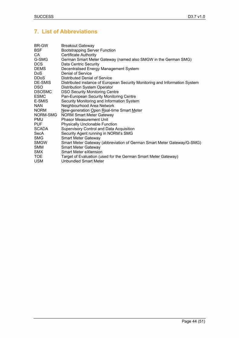
SUCCESS D3.7 v1.0
Page 44 (51)
7. List of Abbreviations
BR-GW Breakout Gateway BSF Bootstrapping Server Function CA Certificate Authority G-SMG German Smart Meter Gateway (named also SMGW in the German SMG) DCS Data Centric Security DEMS Decentralised Energy Management System DoS Denial of Service DDoS Distributed Denial of Service DE-SMIS Distributed instance of European Security Monitoring and Information System DSO Distribution System Operator DSOSMC DSO Security Monitoring Centre ESMC Pan-European Security Monitoring Centre E-SMIS Security Monitoring and Information System NAN Neighbourhood Area Network NORM New-generation Open Real-time Smart Meter NORM-SMG NORM Smart Meter Gateway PMU Phasor Measurement Unit PUF Physically Unclonable Function SCADA Supervisory Control and Data Acquisition SecA Security Agent running in NORM’s SMG SMG Smart Meter Gateway SMGW Smart Meter Gateway (abbreviation of German Smart Meter Gateway/G-SMG) SMM Smart Meter Gateway SMX Smart Meter eXtension TOE Target of Evaluation (used for the German Smart Meter Gateway) USM Unbundled Smart Meter
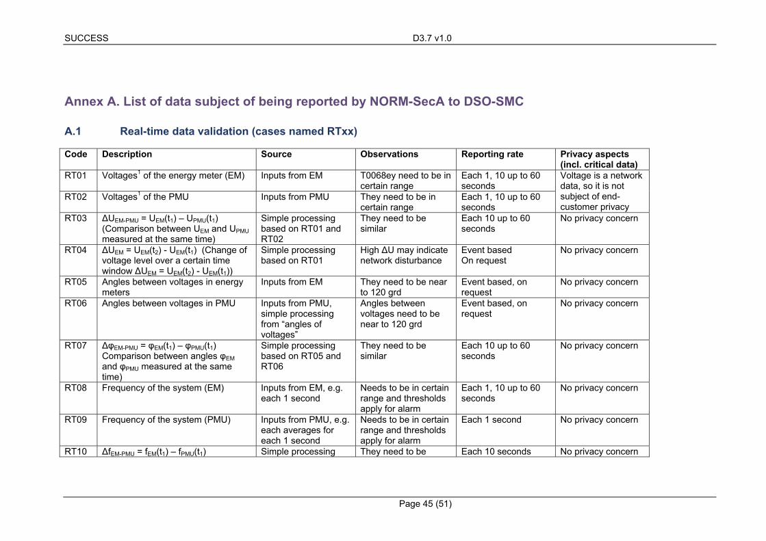
SUCCESS D3.7 v1.0
Page 45 (51)
Annex A. List of data subject of being reported by NORM-SecA to DSO-SMC
A.1 Real-time data validation (cases named RTxx)
Code Description Source Observations Reporting rate Privacy aspects (incl. critical data)
RT01 Voltages1 of the energy meter (EM) Inputs from EM T0068ey need to be in certain range
Each 1, 10 up to 60 seconds
Voltage is a network data, so it is not subject of end-customer privacy
RT02 Voltages1 of the PMU Inputs from PMU They need to be in certain range
Each 1, 10 up to 60 seconds
RT03 ΔUEM-PMU = UEM(t1) – UPMU(t1) (Comparison between UEM and UPMU measured at the same time)
Simple processing based on RT01 and RT02
They need to be similar
Each 10 up to 60 seconds
No privacy concern
RT04 ΔUEM = UEM(t2) - UEM(t1) (Change of voltage level over a certain time window ΔUEM = UEM(t2) - UEM(t1))
Simple processing based on RT01
High ΔU may indicate network disturbance
Event based On request
No privacy concern
RT05 Angles between voltages in energy meters
Inputs from EM They need to be near to 120 grd
Event based, on request
No privacy concern
RT06 Angles between voltages in PMU Inputs from PMU, simple processing from “angles of voltages”
Angles between voltages need to be near to 120 grd
Event based, on request
No privacy concern
RT07 ΔφEM-PMU = φEM(t1) – φPMU(t1) Comparison between angles φEM and φPMU measured at the same time)
Simple processing based on RT05 and RT06
They need to be similar
Each 10 up to 60 seconds
No privacy concern
RT08 Frequency of the system (EM) Inputs from EM, e.g. each 1 second
Needs to be in certain range and thresholds apply for alarm
Each 1, 10 up to 60 seconds
No privacy concern
RT09 Frequency of the system (PMU) Inputs from PMU, e.g. each averages for each 1 second
Needs to be in certain range and thresholds apply for alarm
Each 1 second No privacy concern
RT10 ΔfEM-PMU = fEM(t1) – fPMU(t1) Simple processing They need to be Each 10 seconds No privacy concern
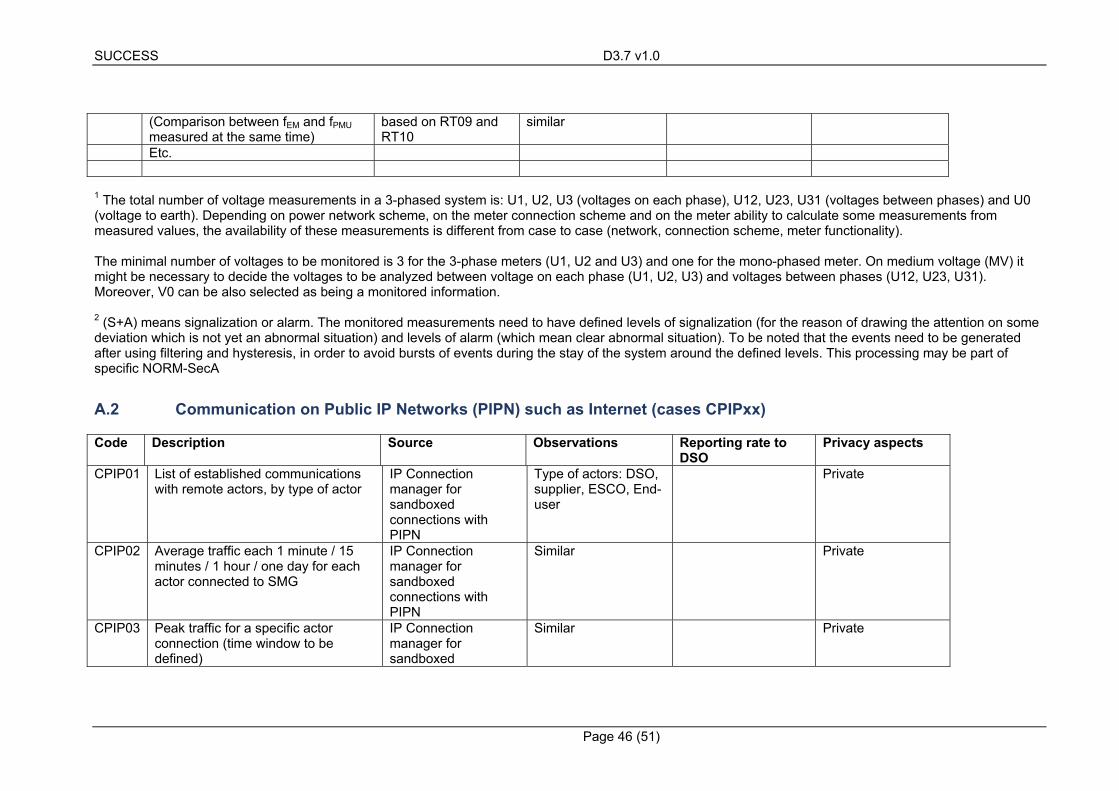
SUCCESS D3.7 v1.0
Page 46 (51)
(Comparison between fEM and fPMU measured at the same time)
based on RT09 and RT10
similar
Etc.
1 The total number of voltage measurements in a 3-phased system is: U1, U2, U3 (voltages on each phase), U12, U23, U31 (voltages between phases) and U0 (voltage to earth). Depending on power network scheme, on the meter connection scheme and on the meter ability to calculate some measurements from measured values, the availability of these measurements is different from case to case (network, connection scheme, meter functionality). The minimal number of voltages to be monitored is 3 for the 3-phase meters (U1, U2 and U3) and one for the mono-phased meter. On medium voltage (MV) it might be necessary to decide the voltages to be analyzed between voltage on each phase (U1, U2, U3) and voltages between phases (U12, U23, U31). Moreover, V0 can be also selected as being a monitored information. 2 (S+A) means signalization or alarm. The monitored measurements need to have defined levels of signalization (for the reason of drawing the attention on some deviation which is not yet an abnormal situation) and levels of alarm (which mean clear abnormal situation). To be noted that the events need to be generated after using filtering and hysteresis, in order to avoid bursts of events during the stay of the system around the defined levels. This processing may be part of specific NORM-SecA
A.2 Communication on Public IP Networks (PIPN) such as Internet (cases CPIPxx)
Code Description Source Observations Reporting rate to DSO
Privacy aspects
CPIP01 List of established communications with remote actors, by type of actor
IP Connection manager for sandboxed connections with PIPN
Type of actors: DSO, supplier, ESCO, End-user
Private
CPIP02 Average traffic each 1 minute / 15 minutes / 1 hour / one day for each actor connected to SMG
IP Connection manager for sandboxed connections with PIPN
Similar Private
CPIP03 Peak traffic for a specific actor connection (time window to be defined)
IP Connection manager for sandboxed
Similar Private
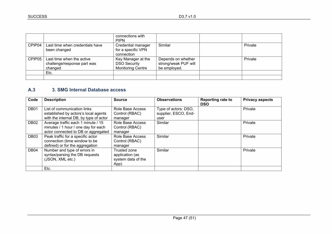
SUCCESS D3.7 v1.0
Page 47 (51)
connections with PIPN
CPIP04 Last time when credentials have been changed
Credential manager for a specific VPN connection
Similar Private
CPIP05 Last time when the active challenge/response part was changed
Key Manager at the DSO Security Monitoring Centre
Depends on whether strong/weak PUF will be employed.
Private
Etc.
A.3 3. SMG Internal Database access
Code Description Source Observations Reporting rate to DSO
Privacy aspects
DB01 List of communication links established by actors’s local agents with the internal DB, by type of actor
Role Base Access Control (RBAC) manager
Type of actors: DSO, supplier, ESCO, End-user
Private
DB02 Average traffic each 1 minute / 15 minutes / 1 hour / one day for each actor connected to DB or aggregated
Role Base Access Control (RBAC) manager
Similar Private
DB03 Peak traffic for a specific actor connection (time window to be defined) or for the aggregation
Role Base Access Control (RBAC) manager
Similar Private
DB04 Number and type of errors in syntax/parsing the DB requests (JSON, XML etc.)
Trusted zone application (as system data of the App)
Similar Private
Etc.
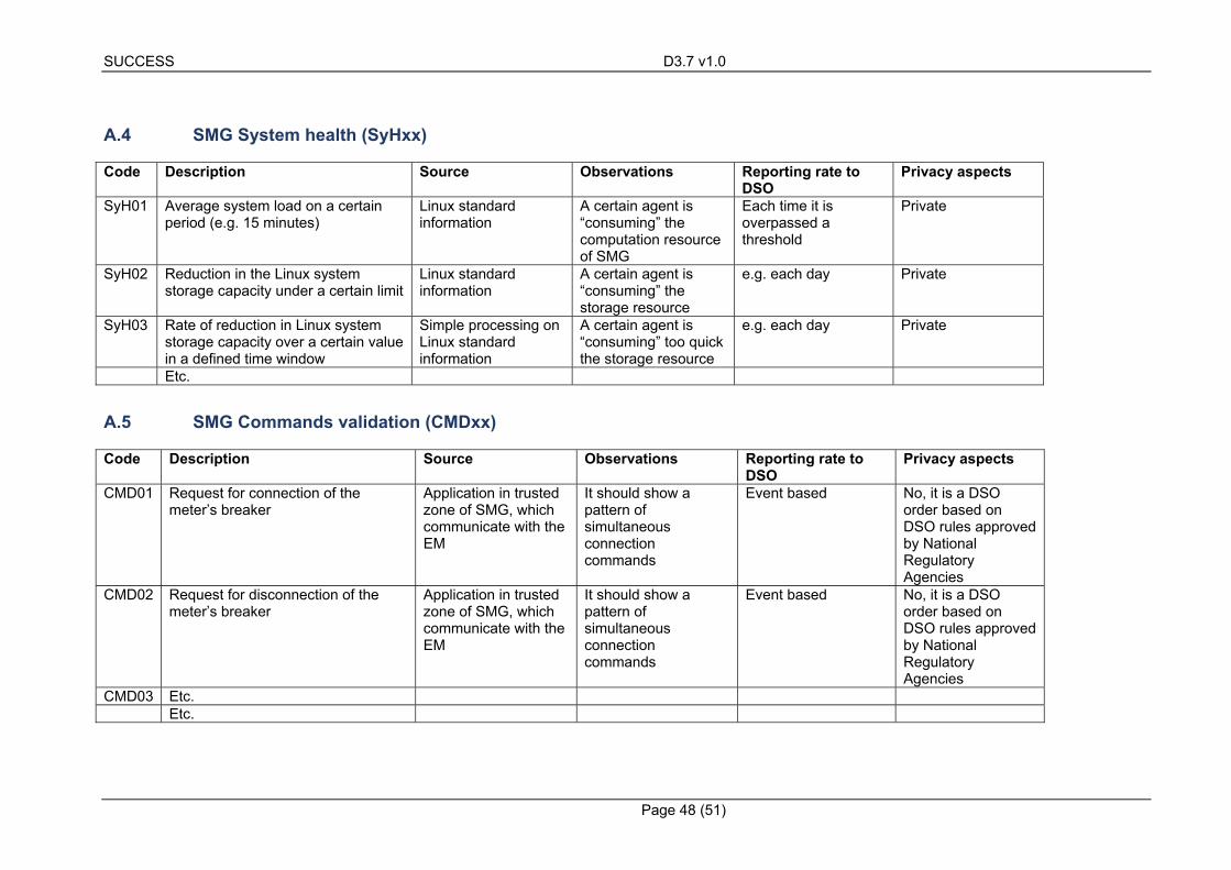
SUCCESS D3.7 v1.0
Page 48 (51)
A.4 SMG System health (SyHxx)
Code Description Source Observations Reporting rate to DSO
Privacy aspects
SyH01 Average system load on a certain period (e.g. 15 minutes)
Linux standard information
A certain agent is “consuming” the computation resource of SMG
Each time it is overpassed a threshold
Private
SyH02 Reduction in the Linux system storage capacity under a certain limit
Linux standard information
A certain agent is “consuming” the storage resource
e.g. each day Private
SyH03 Rate of reduction in Linux system storage capacity over a certain value in a defined time window
Simple processing on Linux standard information
A certain agent is “consuming” too quick the storage resource
e.g. each day Private
Etc.
A.5 SMG Commands validation (CMDxx)
Code Description Source Observations Reporting rate to DSO
Privacy aspects
CMD01 Request for connection of the meter’s breaker
Application in trusted zone of SMG, which communicate with the EM
It should show a pattern of simultaneous connection commands
Event based No, it is a DSO order based on DSO rules approved by National Regulatory Agencies
CMD02 Request for disconnection of the meter’s breaker
Application in trusted zone of SMG, which communicate with the EM
It should show a pattern of simultaneous connection commands
Event based No, it is a DSO order based on DSO rules approved by National Regulatory Agencies
CMD03 Etc. Etc.
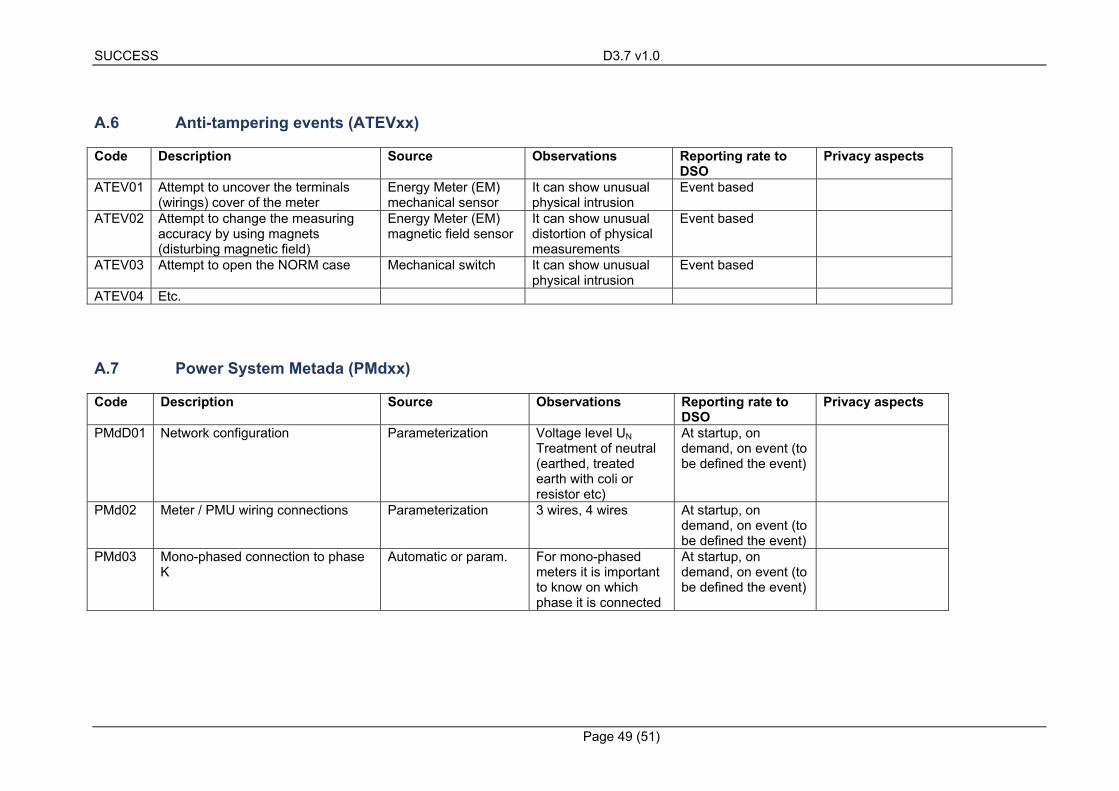
SUCCESS D3.7 v1.0
Page 49 (51)
A.6 Anti-tampering events (ATEVxx)
Code Description Source Observations Reporting rate to DSO
Privacy aspects
ATEV01 Attempt to uncover the terminals (wirings) cover of the meter
Energy Meter (EM) mechanical sensor
It can show unusual physical intrusion
Event based
ATEV02 Attempt to change the measuring accuracy by using magnets (disturbing magnetic field)
Energy Meter (EM) magnetic field sensor
It can show unusual distortion of physical measurements
Event based
ATEV03 Attempt to open the NORM case Mechanical switch It can show unusual physical intrusion
Event based
ATEV04 Etc.
A.7 Power System Metada (PMdxx)
Code Description Source Observations Reporting rate to DSO
Privacy aspects
PMdD01 Network configuration Parameterization Voltage level UN Treatment of neutral (earthed, treated earth with coli or resistor etc)
At startup, on demand, on event (to be defined the event)
PMd02 Meter / PMU wiring connections Parameterization 3 wires, 4 wires At startup, on demand, on event (to be defined the event)
PMd03 Mono-phased connection to phase K
Automatic or param. For mono-phased meters it is important to know on which phase it is connected
At startup, on demand, on event (to be defined the event)
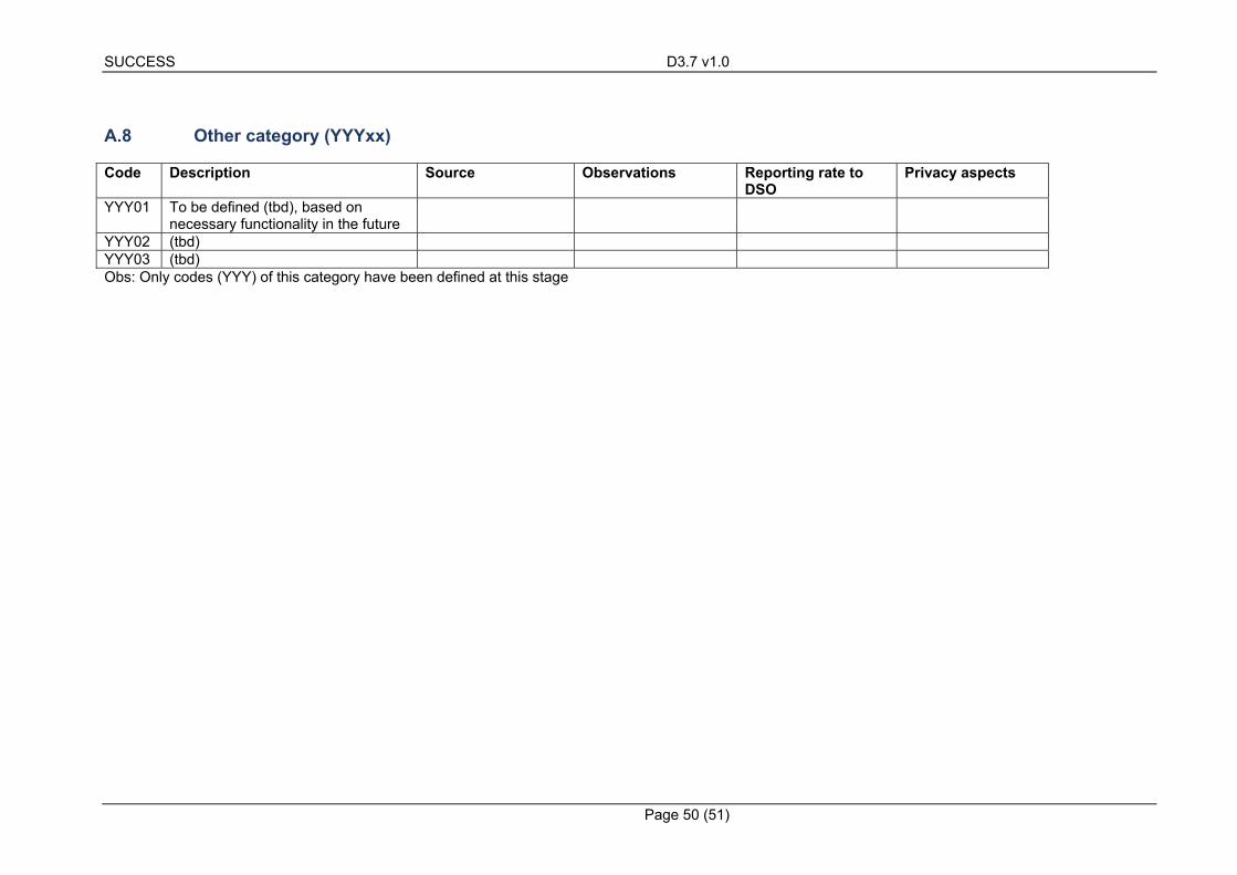
SUCCESS D3.7 v1.0
Page 50 (51)
A.8 Other category (YYYxx)
Code Description Source Observations Reporting rate to DSO
Privacy aspects
YYY01 To be defined (tbd), based on necessary functionality in the future
YYY02 (tbd) YYY03 (tbd) Obs: Only codes (YYY) of this category have been defined at this stage
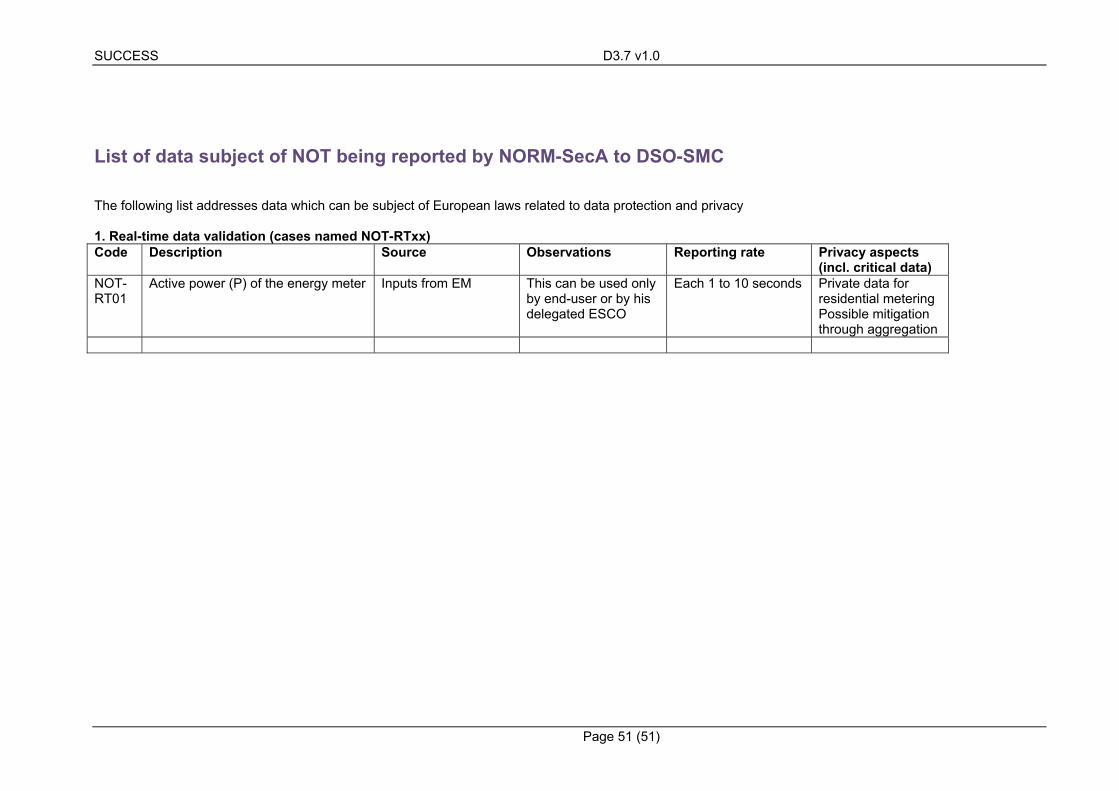
SUCCESS D3.7 v1.0
Page 51 (51)
List of data subject of NOT being reported by NORM-SecA to DSO-SMC
The following list addresses data which can be subject of European laws related to data protection and privacy 1. Real-time data validation (cases named NOT-RTxx) Code Description Source Observations Reporting rate Privacy aspects
(incl. critical data) NOT-RT01
Active power (P) of the energy meter Inputs from EM This can be used only by end-user or by his delegated ESCO
Each 1 to 10 seconds Private data for residential metering Possible mitigation through aggregation