en 302 663 - v1.2.1 - intelligent transport systems (its ... en 302 663 v1.2.1 (2013-07) intelligent...
TRANSCRIPT

ETSI EN 302 663 V1.2.1 (2013-07)
Intelligent Transport Systems (ITS); Access layer specification for
Intelligent Transport Systems operating in the 5 GHz frequency band
European Standard

ETSI
ETSI EN 302 663 V1.2.1 (2013-07) 2
Reference REN/ITS-0040028
Keywords ITS, layer 1, layer 2, MAC, profile, radio
ETSI
650 Route des Lucioles F-06921 Sophia Antipolis Cedex - FRANCE
Tel.: +33 4 92 94 42 00 Fax: +33 4 93 65 47 16
Siret N° 348 623 562 00017 - NAF 742 C
Association à but non lucratif enregistrée à la Sous-Préfecture de Grasse (06) N° 7803/88
Important notice
Individual copies of the present document can be downloaded from: http://www.etsi.org
The present document may be made available in more than one electronic version or in print. In any case of existing or perceived difference in contents between such versions, the reference version is the Portable Document Format (PDF).
In case of dispute, the reference shall be the printing on ETSI printers of the PDF version kept on a specific network drive within ETSI Secretariat.
Users of the present document should be aware that the document may be subject to revision or change of status. Information on the current status of this and other ETSI documents is available at
http://portal.etsi.org/tb/status/status.asp
If you find errors in the present document, please send your comment to one of the following services: http://portal.etsi.org/chaircor/ETSI_support.asp
Copyright Notification
No part may be reproduced except as authorized by written permission. The copyright and the foregoing restriction extend to reproduction in all media.
© European Telecommunications Standards Institute 2013.
All rights reserved.
DECTTM, PLUGTESTSTM, UMTSTM and the ETSI logo are Trade Marks of ETSI registered for the benefit of its Members. 3GPPTM and LTE™ are Trade Marks of ETSI registered for the benefit of its Members and
of the 3GPP Organizational Partners. GSM® and the GSM logo are Trade Marks registered and owned by the GSM Association.

ETSI
ETSI EN 302 663 V1.2.1 (2013-07) 3
Contents
Intellectual Property Rights ................................................................................................................................ 4
Foreword ............................................................................................................................................................. 4
Introduction ........................................................................................................................................................ 4
1 Scope ........................................................................................................................................................ 5
2 References ................................................................................................................................................ 5
2.1 Normative references ......................................................................................................................................... 5
2.2 Informative references ........................................................................................................................................ 6
3 Definitions, symbols and abbreviations ................................................................................................... 7
3.1 Definitions .......................................................................................................................................................... 7
3.2 Symbols .............................................................................................................................................................. 7
3.3 Abbreviations ..................................................................................................................................................... 7
4 General requirements ............................................................................................................................... 8
4.1 Architecture ........................................................................................................................................................ 8
4.2 Frequency allocation ........................................................................................................................................ 10
4.2.1 Introduction................................................................................................................................................. 10
4.2.2 ITS-G5A frequency band ............................................................................................................................ 10
4.2.3 ITS-G5B frequency band ............................................................................................................................ 10
4.2.4 ITS-G5C frequency band ............................................................................................................................ 11
4.2.5 ITS-G5D frequency band ............................................................................................................................ 11
4.3 Channel allocation ............................................................................................................................................ 11
4.4 Transmit requirements ...................................................................................................................................... 12
4.5 Receive requirements ....................................................................................................................................... 12
4.6 Quality of service ............................................................................................................................................. 12
5 ITS-G5 Access layer .............................................................................................................................. 12
5.1 Decentralized Congestion Control ................................................................................................................... 12
5.2 Coexistence between CEN DSRC and ITS-G5 ................................................................................................ 12
6 Conformance and test methods .............................................................................................................. 13
Annex A (normative): MIB parameter .............................................................................................. 14
Annex B (informative): Introduction to IEEE 802.11-2012 [3] .......................................................... 15
B.1 Introduction ............................................................................................................................................ 15
B.2 Network topology ................................................................................................................................... 16
B.3 Physical layer ......................................................................................................................................... 16
B.4 Medium access control ........................................................................................................................... 17
B.4.1 Introduction ...................................................................................................................................................... 17
B.4.2 Backoff procedure ............................................................................................................................................ 18
B.4.3 Medium access control ..................................................................................................................................... 18
B.4.4 EDCA parameters, AC and UP ........................................................................................................................ 19
B.5 Implications of the dot11OCBActivated set to true ............................................................................... 21
Annex C (informative): ITS-G5C frequency band .............................................................................. 22
Annex D (informative): Bibliography ................................................................................................... 23
History .............................................................................................................................................................. 24
ETSI
ETSI EN 302 663 V1.2.1 (2013-07) 4
Intellectual Property Rights IPRs essential or potentially essential to the present document may have been declared to ETSI. The information pertaining to these essential IPRs, if any, is publicly available for ETSI members and non-members, and can be found in ETSI SR 000 314: "Intellectual Property Rights (IPRs); Essential, or potentially Essential, IPRs notified to ETSI in respect of ETSI standards", which is available from the ETSI Secretariat. Latest updates are available on the ETSI Web server (http://ipr.etsi.org).
Pursuant to the ETSI IPR Policy, no investigation, including IPR searches, has been carried out by ETSI. No guarantee can be given as to the existence of other IPRs not referenced in ETSI SR 000 314 (or the updates on the ETSI Web server) which are, or may be, or may become, essential to the present document.
Foreword This European Standard (EN) has been produced by ETSI Technical Committee Intelligent Transport Systems (ITS).
National transposition dates
Date of adoption of this EN: 2 July 2013
Date of latest announcement of this EN (doa): 31 October 2013
Date of latest publication of new National Standard or endorsement of this EN (dop/e):
30 April 2014
Date of withdrawal of any conflicting National Standard (dow): 30 April 2014
Introduction The present document is outlining the two lowest layers - physical layer and data link layer - in the protocol stack for supporting vehicle-to-vehicle communications in an ad hoc network to be used at the 5,9 GHz frequency band allocated in Europe. The two lowest layers are termed access layer in the present document and the technology specified for the access layer is collectively called ITS-G5. The ITS-G5 standard is using already existing standards for communications. The data link layer is divided into two sublayers; medium access control and logical link control. The physical layer and the medium access control layer are covered in IEEE 802.11-2012 [3]. The logical link control is based on the IEEE/ISO/IEC 8802-2-1998 [5]. The ITS-G5 standard also adds features for decentralized congestion control (DCC) methods TS 102 687 [8] to control the network load and avoid unstable behaviour.
By setting the management information base (MIB) parameter dot11OCBActivated to true in IEEE 802.11-2012 [3] a new capability is introduced namely the possibility to communicate outside the context of a basic service set (BSS), which is the smallest building block of a 802.11 network. Communication outside the BSS implies that neither authentication/association procedures nor security mechanisms are supported. Further, no access point functionality is present. The disable of these features also affects other built-in features of IEEE 802.11-2012 [3]. The requirement that nodes should share a common clock is no longer valid while dot11OCBActivated is true. Further, scanning of available frequency channels for joining a BSS is also disabled implying that communication outside the context of the BSS requires that a node is configured for a predetermined frequency channel where more information about other available frequency channels can be obtained.
NOTE: IEEE has compiled a new version of the 802.11 standard where all approved amendments produced between 2007 and 2011 have been enrolled in the base standard including 802.11p. This new version called IEEE 802.11-2012 [3] was approved in March 2012. Due to this new version of 802.11 the 802.11p amendment is classified as superseded.

ETSI
ETSI EN 302 663 V1.2.1 (2013-07) 5
1 Scope The scope of the present document is to define the two lowest layers, physical layer and the data link layer, grouped into the access layer of the ITS station reference architecture EN 302 665 [i.8]. The access layer technology that is specified in the present document is collectively called ITS-G5. It is part of the communication stack supporting data exchange between mobile stations without prior network set-up, i.e. ad hoc mode, for the following frequency bands in Europe:
• ITS-G5A: Operation of ITS-G5 in European ITS frequency bands dedicated to ITS for safety related applications in the frequency range 5,875 GHz to 5,905 GHz.
• ITS-G5B: Operation in European ITS frequency bands dedicated to ITS non-safety applications in the frequency range 5,855 GHz to 5,875 GHz.
• ITS-G5D: Operation of ITS applications in the frequency range 5,905 GHz to 5,925 GHz.
The ITS-G5 technology is based on IEEE 802.11-2012 [3] and IEEE/ISO/IEC 8802-2-1998 [5]. By setting the MIB variable dot11OCBActivated to true in IEEE 802.11-2012 [3] communication outside the context of a BSS is possible. This type of communication allows for immediate exchange of data frames, avoiding the management overhead used with the establishment of a network. All requirements in IEEE 802.11-2012 [3] associated with communication "outside the context of a BSS" are also requirements in the present document. All optional functionality in IEEE 802.11-2012 [3] associated with communication "outside the context of a BSS" is also optional in the present document.
2 References References are either specific (identified by date of publication and/or edition number or version number) or non-specific. For specific references, only the cited version applies. For non-specific references, the latest version of the reference document (including any amendments) applies.
Referenced documents which are not found to be publicly available in the expected location might be found at http://docbox.etsi.org/Reference.
NOTE: While any hyperlinks included in this clause were valid at the time of publication, ETSI cannot guarantee their long term validity.
2.1 Normative references The following referenced documents are necessary for the application of the present document.
[1] ETSI EN 302 571 (V1.1.1): "Intelligent Transport Systems (ITS); Radiocommunications equipment operating in the 5 855 MHz to 5 925 MHz frequency band; Harmonized EN covering the essential requirements of article 3.2 of the R&TTE Directive".
[2] ETSI TS 102 792 (V1.1.1): "Intelligent Transport Systems (ITS); Mitigation techniques to avoid interference between European CEN Dedicated Short Range Communication (CEN DSRC) equipment and Intelligent Transport Systems (ITS) operating in the 5 GHz frequency range".
[3] IEEE 802.11-2012: "IEEE Standard for Information technology - Telecommunications and information exchange between systems - Local and metropolitan area networks-Specific requirements - Part 11: Wireless LAN Medium Access Control (MAC) and Physical Layer (PHY) Specifications".
[4] IEEE 802-2001: "IEEE Standard for Local and Metropolitan Area Networks: Overview and Architecture".
[5] IEEE/ISO/IEC 8802-2-1998: "Information technology -- Telecommunications and information exchange between systems -- Local and metropolitan area networks -- Specific requirements -- Part 2: Logical Link Control".

ETSI
ETSI EN 302 663 V1.2.1 (2013-07) 6
[6] ISO/IEC 7498-1:1994: "Information technology - Open Systems Interconnection - Basic Reference Model: The Basic Model".
[7] Recommendation ITU-T X.691 (2008): "Information technology - ASN.1 encoding rules: Specification of Packed Encoding Rules (PER)".
[8] ETSI TS 102 687 (V1.1.1): "Intelligent Transport Systems (ITS); Decentralized Congestion Control Mechanisms for Intelligent Transport Systems operating in the 5 GHz range; Access layer part".
2.2 Informative references The following referenced documents are not necessary for the application of the present document but they assist the user with regard to a particular subject area.
[i.1] ETSI EN 300 674 (all parts): "Electromagnetic compatibility and Radio spectrum Matters (ERM); Road Transport and Traffic Telematics (RTTT); Dedicated Short Range Communication (DSRC) transmission equipment (500 kbit/s / 250 kbit/s) operating in the 5,8 GHz Industrial, Scientific and Medical (ISM) band".
[i.2] ECC/REC/(08)01: "ECC Recommendation (08)01 on the use of the band 5855-5875 MHz for Intelligent Transport Systems (ITS)".
[i.3] ERC/DEC(99)23: "ERC Decision of 29 November 1999 on the harmonised frequency bands to be designated for the introduction of High Performance Radio Local Area Networks (HIPERLANs)".
[i.4] ECC/DEC(02)01: "ECC Decision of 15 March 2002 on the frequency bands to be designated for the co-ordinated introduction of Road Transport and Traffic Telematic Systems".
[i.5] Commission Decision 2005/513/EC of 11 July 2005 on the harmonised use of radio spectrum in the 5 GHz frequency band for the implementation of wireless access systems including radio local area networks (WAS/RLANs).
[i.6] Commission Decision 2007/90/EC of 12 February 2007 amending Decision 2005/513/EC on the harmonised use of radio spectrum in the 5 GHz frequency band for the implementation of Wireless Access Systems including Radio Local Area Networks (WAS/RLANs).
[i.7] Commission Decision 2008/671/EC of 5 August 2008 on the harmonised use of radio spectrum in the 5 875-5 905 MHz frequency band for safety-related applications of Intelligent Transport Systems (ITS).
[i.8] ETSI EN 302 665 (V1.1.1): "Intelligent Transport Systems (ITS); Communications Architecture".
[i.9] ETSI TS 102 724 (V0.0.11): "Intelligent Transport Systems (ITS); Harmonized Channel Specifications for Intelligent Transport Systems operating in the 5 GHz frequency band".
[i.10] ANSI/IEEE Std 802.1D 1998: "IEEE Standard for Information technology - Telecommunications and information exchange between systems - Local and metropolitan area networks - Common specifications- Part 3: Media Access Control (MAC) Bridges".
[i.11] IEEE 802.11p-2010: "IEEE Standard for Information technology-- Local and metropolitan area networks-- Specific requirements-- Part 11: Wireless LAN Medium Access Control (MAC) and Physical Layer (PHY) Specifications Amendment 6: Wireless Access in Vehicular Environments".
[i.12] IEEE 802.11a-1999: "IEEE Standard for Telecommunications and Information Exchange Between Systems - LAN/MAN Specific Requirements - Part 11: Wireless Medium Access Control (MAC) and physical layer (PHY) specifications: High Speed Physical Layer in the 5 GHz band".
[i.13] IEEE 802.11e-2005: "IEEE Standard for Information technology-- Local and metropolitan area networks-- Specific requirements-- Part 11: Wireless LAN Medium Access Control (MAC) and Physical Layer (PHY) Specifications - Amendment: Medium Access Method (MAC) Quality of Service Enhancements".

ETSI
ETSI EN 302 663 V1.2.1 (2013-07) 7
[i.14] ETSI EN 301 893 (V1.5.1): "Broadband Radio Access Networks (BRAN); 5 GHz high performance RLAN; Harmonized EN covering the essential requirements of article 3.2 of the R&TTE Directive".
[i.15] ETSI EN 302 502 (V1.2.1): "Broadband Radio Access Networks (BRAN); 5,8 GHz fixed broadband data transmitting systems; Harmonized EN covering the essential requirements of article 3.2 of the R&TTE Directive".
3 Definitions, symbols and abbreviations
3.1 Definitions For the purposes of the present document, the terms and definitions given in EN 302 571 [1], TS 102 792 [2], IEEE 802.11-2012 [3], IEEE 802-2001 [4], IEEE/ISO/IEC 8802-2-1998 [5], ISO/IEC 7498-1 [6], Recommendation ITU-T X.691 [7] and the following apply:
ethertype: identifier to the network protocol above the data link layer
ITS-G5: access technology to be used in frequency bands dedicated for European intelligent transport System (ITS)
ITS-G5 Control Channel: physical channel for ITS-G5
ITS-G5 Service Channel: physical channel for ITS-G5
ITS-G5 Station: ITS station that operates using ITS-G5 channels
3.2 Symbols For the purposes of the present document, the following symbols apply:
aCWmax Maximum value of Contention Window aCWmin Minimum value of Contention Window AIFS Arbitration InterFrame Space AIFSN Arbitration InterFrame Space Number aSIFSTime Short InterFrame Space defined by the physical layer aSlotTime A slot time defined by the physical layer CW Contention Window CWmax Maximum value of Contention Window
CWmin Minimum value of Contention Window
3.3 Abbreviations For the purposes of the present document, the following abbreviations apply:
AC Access Category AC_BE Access Category Best Effort AC_BK Access Category Background AC_VI Access Category Video AC_VO Access Category Voice ACK Acknowledgment AIFS Arbitration InterFrame Space AIFSN Arbitration InterFrame Space Number AP Access Point BE Best Effort BK Background BPSK Binary Phase Shift Keying BRAN Broadband Radio Access Network BSS Basic Service Set

ETSI
ETSI EN 302 663 V1.2.1 (2013-07) 8
BSSID Basic Service Set Identification CCH Control Channel CEN European Committee for Standardisation CSMA/CA Carrier Sense Multiple Access with Collision Avoidance CW Contention Window DCC Decentralized Congestion Control DCF Distributed Coordination Function DFS Dynamic Frequency Selection DIFS Distributed InterFrame Space DSRC Dedicated Short-Range Communication ECC Electronic Communication Committee EDCA Enhanced Distribution Coordination Access EE Excellent Effort EIRP Effective Isotropic Radiated Power EN European Norm G5-CCH ITS-G5 Control Channel G5-SCH ITS-G5 Service Channel GPS Global Positioning System IBSS Independent Basic Service Set IEEE Institute of Electrical and Electronics Engineers ITS Intelligent Transport System ITS-G5A Frequency band ranging from 5 875 MHz to 5 905 MHz ITS-G5B Frequency band ranging from 5 855 MHz to 5 875 MHz ITS-G5C Frequency band ranging from 5 470 MHz to 5 725 MHz ITS-G5D Frequency band ranging from 5 905 MHz to 5 925 MHz LLC Logical Link Control MAC Medium Access Control MIB Management Information Base MPDU MAC Protocol Data Unit NC Network Control OFDM Orthogonal Frequency Division Multiplexing OSI Open Systems Interconnect PHY Physical layer PLCP Physical Layer Convergence Protocol PPDU PLCP Protocol Data Unit PSDU PLCP Service Data Unit QAM Quadrature Amplitude Modulation QoS Quality of Service QPSK Quadrature Phase Shift Keying RLAN Radio Local Area Network SNAP SubNetwork Access Protocol TPC Transmit Power Control TR Technical Report TS Technical Specification TX Transmitter UP User Priority VI Video VO Voice WLAN Wireless Local Area Network
4 General requirements
4.1 Architecture Figure 1 shows the ITS station reference architecture EN 302 665 [i.8]. The present document specifies one access technology for cooperative ITS namely ITS-G5 based on IEEE 802.11-2012 [3]. The access layer of the ITS station reference architecture includes both the physical layer and the data link layer of the OSI model.

ETSI
ETSI EN 302 663 V1.2.1 (2013-07) 9
Figure 1: ITS station reference architecture
In Figure 2 the ITS-G5 access layer architecture is outlined. The security entity shown in Figure 1 is included as a part of the management entity EN 302 665 [i.8].
Medium Access Control (MAC)
Logical Link Control (LLC)
Physical layer (PHY)
ITS-G5 Access layer
IN-SAP
MI-
SA
P
Figure 2: ITS-G5 access layer architecture
An ITS-G5 station shall be compliant with the following IEEE standards:
1) The physical (PHY) layer orthogonal frequency division multiplexing (OFDM) as defined in clause 18 of IEEE 802.11-2012 [3].
2) The medium access control (MAC) layer functionality as defined in IEEE 802.11-2012 [3] by setting the MIB parameter dot11OCBActivated to true enabling communication outside the context of a basic service set (BSS).
3) The logical link control (LLC) as defined in IEEE/ISO/IEC 8802-2-1998 [5] and the mode of operation is set to Type 1 - unacknowledged connectionless mode.
4) The subnetwork access protocol (SNAP) as defined in IEEE 802-2001 [4].
An ITS-G5 station shall comply to the functionality defined in clause 5 ITS-G5 Access layer.
The SNAP provides the possibility to distinguish between different network protocols through EtherTypes.
In annex B an informative introduction to IEEE 802.11-2012 [3], where the MIB parameter dot11OCBActivated is set to true, is given to facilitate the reading of the present document.

ETSI
ETSI EN 302 663 V1.2.1 (2013-07) 10
4.2 Frequency allocation
4.2.1 Introduction
Table 1 shows the frequency ranges, related regulatory requirements, intended usage and harmonized standards to be used for cooperative ITS within the European Union.
Table 1: Frequency allocation in the European Union
Frequency range [MHz]
Usage Regulation Harmonized standard
ITS-G5D 5 905 to 5 925 Future ITS applications ECC Decision ECC/DEC(02)01 [i.4] EN 302 571 [1] ITS-G5A 5 875 to 5 905 ITS road safety related
applications Commission Decision 2008/671/EC [i.7] EN 302 571 [1]
ITS-G5B 5 855 to 5 875 ITS non-safety applications
ECC Recommendation ECC/REC/(08)01 [i.2]
EN 302 571 [1]
ITS-G5C 5 470 to 5 725 RLAN (BRAN, WLAN) ERC Decision ERC/DEC(99)23 [i.3] Commission Decisions 2005/513/EC [i.5] and 2007/90/EC [i.6]
EN 301 893 [i.14]
NOTE: The Commission Decision 2008/671/ECC [i.7] is in line with the ECC Decision ECC/DEC(02)01 [i.4].
Figure 3 illustrates the channel allocation in the 5 GHz range for the frequency bands listed in Table 1. It also shows the European bands for Dedicated Short Range Communication (DSRC), which in Europe refers to the EN 300 674 [i.1] used for electronic toll collection (so called CEN DSRC), for instance. DSRC is regulated by the ECC Decision ECC/DEC(02)01 [i.4].
CEN DSRC
ITS road safety (ITS-G5A)
Future ITS applications(ITS-G5D)
ITS non-safety applications (ITS-G5B)
Figure 3: Channel allocation for the 5 GHz frequency range
4.2.2 ITS-G5A frequency band
The ITS-G5A frequency band is set aside for ITS road traffic safety applications and it is only allowed to be used by ITS-G5 compliant stations as specified in the present document.
4.2.3 ITS-G5B frequency band
The ITS-G5B frequency band is set aside for ITS non-safety road traffic applications and it is only allowed to be used by ITS-G5 compliant stations as specified in the present document.

ETSI
ETSI EN 302 663 V1.2.1 (2013-07) 11
4.2.4 ITS-G5C frequency band
The conditions for using the ITS-G5C band are given in the Commission Decisions 2005/513/EC [i.5] and 2007/90/EC [i.6]. The technical requirements for this band are detailed in EN 301 893 [i.14].
NOTE: The ITS-G5C band is also referred to broadband radio access networks (BRAN), radio local area network (RLAN) and wireless local area network (WLAN).
Operation in the RLAN band requires transmit power control (TPC), a procedure for dynamic frequency selection (DFS) and uniform spreading, in order to detect signals from radar systems and to avoid co-channel interference. This functionality is not supported when setting the MIB parameter dot11OCBActivated to true. Therefore, it is not possible to use the ITS-G5 stations for communication in the ITS-G5C band outside the context of a basic service set, the rationale behind this is detailed in the informative annex C.
4.2.5 ITS-G5D frequency band
This frequency band is set aside for future usage of ITS road traffic applications and it is allowed to be used by ITS-G5 compliant stations as specified in the present document.
4.3 Channel allocation Channel allocation shall be as specified in Table 1. One physical channel is allocated to be the control channel (CCH), termed G5-CCH. Seven fixed service channels and one variable physical service channel are identified as G5-SCHs.
Table 2: European channel allocation
Channel type Centre frequency
IEEE 802.11-2012 [3] channel
number
Channel spacing
Default data rate
TX power limit TX power density limit
G5-CCH 5 900 MHz 180 10 MHz 6 Mbit/s 33 dBm EIRP 23 dBm/MHz G5-SCH2 5 890 MHz 178 10 MHz 12 Mbit/s 23 dBm EIRP 13 dBm/MHz G5-SCH1 5 880 MHz 176 10 MHz 6 Mbit/s 33 dBm EIRP 23 dBm/MHz G5-SCH3 5 870 MHz 174 10 MHz 6 Mbit/s 23 dBm EIRP 13 dBm/MHz G5-SCH4 5 860 MHz 172 10 MHz 6 Mbit/s 0 dBm EIRP -10 dBm/MHz G5-SCH5 5 910 MHz 182 10 MHz 6 Mbit/s 0 dBm EIRP -10 dBm/MHz G5-SCH6 5 920 MHz 184 10 MHz 6 Mbit/s 0 dBm EIRP -10 dBm/MHz G5-SCH7 As described in
EN 301 893 [i.14] for the band
5 470 MHz to 5 725 MHz
94 to 145 several dependent on channel spacing
30 dBm EIRP (DFS master)
17 dBm/MHz
23 dBm EIRP (DFS slave)
10 dBm/MHz
NOTE: With respect to emission limits (power limit/power density limit), the more stringent requirement applies.
The usage of G5-CCH and G5-SCH1 to G5-SCH2 are dedicated basically for ITS road safety. G5-SCH3 to G5-SCH5 are essentially dedicated for ITS road traffic efficiency. A more detailed description of usage is defined in TS 102 724 [i.9]. In Table 3 the different physical channels are mapped to the frequency ranges found in Table 1 for clarification.
Table 3: European channel allocation
Channel type Frequency range [MHz] IEEE channel number
ITS-G5A G5-CCH 5 895 to 5 905 180 G5-SCH2 5 885 to 5 895 178 G5-SCH1 5 875 to 5 885 176
ITS-G5B G5-SCH3 5 865 to 5 875 174 G5-SCH4 5 855 to 5 865 172
ITS-G5C G5-SCH7 5 470 to 5 725 94 to 145 ITS-G5D G5-SCH5 5 905 to 5 915 182 ITS-G5D G5-SCH6 5 915 to 5 925 184
ETSI
ETSI EN 302 663 V1.2.1 (2013-07) 12
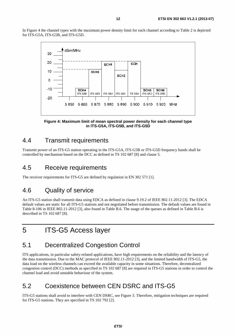
In Figure 4 the channel types with the maximum power density limit for each channel according to Table 2 is depicted for ITS-G5A, ITS-G5B, and ITS-G5D.
5 850 5 860 5 870 5 880 5 890 5 900 5 910 5 920 MHz
SCH4
30
20
10
0
-10
-20
SCH3
SCH1
SCH2
CCH
SCH5 SCH6
dBm/MHz
ITS-G5A ITS-G5A ITS-G5AITS-G5BITS-G5B ITS-G5D ITS-G5D
Figure 4: Maximum limit of mean spectral power density for each channel type in ITS-G5A, ITS-G5B, and ITS-G5D
4.4 Transmit requirements Transmit power of an ITS-G5 station operating in the ITS-G5A, ITS-G5B or ITS-G5D frequency bands shall be controlled by mechanism based on the DCC as defined in TS 102 687 [8] and clause 5.
4.5 Receive requirements The receiver requirements for ITS-G5 are defined by regulation in EN 302 571 [1].
4.6 Quality of service An ITS-G5 station shall transmit data using EDCA as defined in clause 9.19.2 of IEEE 802.11-2012 [3]. The EDCA default values are static for all ITS-G5 stations and not negotiated before transmission. The default values are found in Table 8-106 in IEEE 802.11-2012 [3], also found in Table B.6. The usage of the queues as defined in Table B.6 is described in TS 102 687 [8].
5 ITS-G5 Access layer
5.1 Decentralized Congestion Control ITS applications, in particular safety-related applications, have high requirements on the reliability and the latency of the data transmission. Due to the MAC protocol of IEEE 802.11-2012 [3], and the limited bandwidth of ITS-G5, the data load on the wireless channels can exceed the available capacity in some situations. Therefore, decentralized congestion control (DCC) methods as specified in TS 102 687 [8] are required in ITS-G5 stations in order to control the channel load and avoid unstable behaviour of the system.
5.2 Coexistence between CEN DSRC and ITS-G5 ITS-G5 stations shall avoid to interfere with CEN DSRC, see Figure 3. Therefore, mitigation techniques are required for ITS-G5 stations. They are specified in TS 102 792 [2].

ETSI
ETSI EN 302 663 V1.2.1 (2013-07) 13
6 Conformance and test methods Declaration of conformity of the ITS-G5 physical layer with European Harmonized Standards shall be done according to EN 302 571 [1].
Conformance and test methods for the ITS-G5 communication protocols are not specified in the present document.

ETSI
ETSI EN 302 663 V1.2.1 (2013-07) 14
Annex A (normative): MIB parameter Table A.1 defines the relevant value of the MIB parameter specified in IEEE 802.11-2012 [3] that shall be set by ITS-G5 stations using ITS-G5A, ITS-G5B, and ITS-G5D bands.
Table A.1: MIB parameter
Name Initial value Value may be changed
Remark
dot11OCBActivated True No Specified in IEEE 802.11-2012 [3]. When True, operation outside the context of a BSS applies.

ETSI
ETSI EN 302 663 V1.2.1 (2013-07) 15
Annex B (informative): Introduction to IEEE 802.11-2012
B.1 Introduction The aim with the present informative annex is to introduce the reader of the present document to the IEEE 802.11-2012 [3] when used in the vehicular environment.
NOTE 1: The annex is a brief introduction and the reader is referred to IEEE 802.11-2012 [3] for further details.
In March 2012, the amendment IEEE 802.11p-2010 [i.11] was classified as superseded and enrolled into the new version of IEEE 802.11-2012 [3]. IEEE 802.11p-2010 [i.11] was developed to support new emerging applications utilizing wireless communication between vehicles in an effort to decrease road traffic accidents and improve road traffic efficiency. IEEE 802.11p-2010 [i.11] added a new management information base (MIB) variable called dot11OCBActivated and by setting this to true a new capability in the IEEE 802.11-2012 [3] is introduced namely the possibility to communicate outside the context of a basic service set (BSS), which is the smallest building block of an 802.11 network. The side effect of this are that the BSS authentication and association procedures are removed because this is a time consuming process and in a vehicular environment where nodes are highly mobile and transactions may not be completed until the nodes are out of each other's radio ranges. The communication outside of a BSS can be thought of as ad hoc communications and should not be confused with the independent BSS network topology supported in IEEE 802.11-2012 [3]. To distinguish between communication within a BSS and outside of a BSS the network identification (basic service set id, BSSID) is set to a wildcard in every frame transmitted in an 802.11p communications. The removal of authentication and association procedures implies further changes to IEEE 802.11-2012 [3], which will be outlined in the following clauses.
NOTE 2: An amendment is an improvement to an already existing work implying that IEEE 802.11p-2010 [i.11] was not standalone and knowledge about the core IEEE Std 802.11 [3] was necessary to understand the functionality of IEEE Std 802.11p [i.11].
NOTE 3: All primitives ending with "Enabled" in the former published version of IEEE Std 802.11 [3] have changed name to "Activated" in the new version IEEE 802.11-2012 [3].
NOTE 4: To facilitate the reading of the current annex the name 802.11p will be used throughout the text referring when the dot11OCBActivated is set to true enabling communication outside the context of a BSS in IEEE 802.11-2012 [3]. The references to specific clauses will be made to IEEE 802.11-2012 [3] and not the superseded IEEE Std 802.11p-2010 [i.11].
IEEE Std 802.11 [3] offers several physical (PHY) layers and one common medium access control (MAC) sublayer with Quality of Service (QoS) support. IEEE 802.11p-2010 [i.11] is using the orthogonal frequency division multiplexing (OFDM) PHY detailed in clause 18 of IEEE 802.12-2012 [3] (a.k.a. IEEE 802.11a-1999 [i.12]), with minor additions, and it has support for QoS through the former amendment called IEEE 802.11e-2005 [i.13] (approved in 2004 and enrolled in IEEE 802.11-2012 [3]).

ETSI
ETSI EN 302 663 V1.2.1 (2013-07) 16
B.2 Network topology The IEEE 802.11-2012 [3] standard contains two basic network topologies IEEE 802.11-2012 [3]: the infrastructure BSS and the independent BSS (IBSS). The former contains an access point (AP) and data traffic usually takes a detour through the AP even though two nodes are closely co-located. The IBSS is a set of nodes communicating directly with each other and this is also called ad hoc or peer-to-peer network. Both these topologies are aimed for nomadic devices and synchronization is required between nodes performed via beacons. Further, they are identified with a unique BSSID. Association and authentication are required in infrastructure BSS whereas in IBSS association is not used and communication can take place in an unauthenticated mode. With the introduction of 802.11p a new capability of the 802.11 is introduced, namely communication outside the context of a BSS, see clause 4.3.11 of IEEE 802.11-2012 [3]. The communication outside of a BSS is enabled by setting the MIB variable dot11OCBActivated to true. In this mode authentication, association and security between nodes are disabled at the MAC sublayer. This implies that active and passive scanning of BSS and IBSS are disabled. The scanning on frequency channels for the node in order to join an existing network is no longer enabled. Therefore, the implementation of 802.11p in the vehicular environment requires predetermined frequency channels such as the G5-CCH to be set in the management.
B.3 Physical layer The PHY in 802.11p is OFDM detailed in clause 18 of 802.11. The basic idea is to divide the available frequency spectrum into narrower subchannels (subcarriers). The high-rate data stream is split into a number of lower-rate data streams transmitted simultaneously over a number of subcarriers, where each subcarrier is narrow banded. There are 52 subcarriers, where 48 are used for data and 4 are pilot carriers. The OFDM PHY layer has support for eight different transfer rates, which are achieved by using different modulation schemes and coding rates. In Table B.1 the different transfer rates together with the coding schemes used in 802.11p are tabulated for 10 MHz frequency channels. Support of three transfer rates are mandatory; 3 Mbit/s, 6 Mbit/s, and 12 Mbit/s.
NOTE: The OFDM PHY supports 3 different frequency channel bandwidths, i.e. 5 MHz, 10 MHz and 20 MHz, where the latter is commonly used for WLAN at 5 GHz and 10 MHz is used for the vehicular environment at 5,9 GHz.
Table B.1: Transfer rates, modulation schemes and coding rates in 802.11p
Transfer rate [Mbit/s]
Modulation scheme
Coding rate Data bits per OFDM symbol
Coded bits per OFDM symbol
3 BPSK 1/2 24 48 4,5 BPSK 3/4 36 48 6 QPSK 1/2 48 96 9 QPSK 3/4 72 96
12 16-QAM 1/2 96 192 18 16-QAM 3/4 144 192 24 64-QAM 2/3 192 288 27 64-QAM 3/4 216 288
In Figure B.1 the resulting PHY packet is depicted, i.e. the physical layer convergence procedure (PLCP) protocol data unit (PPDU). The PLCP service data unit (PSDU) contains the data from the MAC layer including MAC header and trailer (collectively named MAC protocol data unit, MPDU). The preamble is used for synchronizing the receiver and the signal field contains information about the packet length and at what data rate the data field is transmitted with. The signal field is always transmitted using BPSK with a coding rate of 1/2. The duration of one OFDM symbol is 8 µs in 802.11p and depending on the modulation scheme and coding rate different numbers of data bits can be carried in each OFDM symbol, see Table B.1. The signal field consists of 24 bits transmitted with the lowest transfer rates and therefore it takes 8 µs.

ETSI
ETSI EN 302 663 V1.2.1 (2013-07) 17
PSDU Rate 4 bits
Res. 1 bit
Length 12 bits
Parity 1 bit
Tail 6 bits
Service 16 bits
Tail 6 bits
Pad bits
Preamble Signal Data
Figure B.1: The resulting PHY packet, i.e. PPDU, ready for transmission
In Table B.2 an explanation to all the different fields in the packet is given together with duration for 10 MHz frequency channels. The preamble and the signal field have fixed duration.
Table B.2: Explanation of the different fields of the PPDU
Field Subfield Description Duration [µs]
Preamble N/A Synchronizing receiver. Consists of a short and a long training sequence. 32
Signal
Rate Specifies the transfer rate at which the data field in the PPDU will be transmitted.
8 Reserved For future use. Length The length of the packet. Parity Parity bit. Tail Used for facilitate decoding and calculation
of rate and length subfields.
Data
Service Used for synchronizing the descrambler at receiver.
Depending on selected transfer rate and packet length.
PSDU The data from the MAC layer including header and trailer, i.e. MPDU.
Tail Used for putting the convolutional encoder to zero state.
Pad bits Bits added to reach a multiple of coded bits per OFDM symbol (i.e. 48, 96, 192, 288, see Table B.1).
More details about the PHY are found in clause 18 of IEEE 802.11-2012 [3].
B.4 Medium access control
B.4.1 Introduction The MAC algorithm decides when in time a node is allowed to transmit based on the current channel status and the MAC schedules transmission with the goal to minimize the interference in the system to increase the packet reception probability. The MAC algorithm deployed by 802.11p is found in the IEEE 802.11-2012 [3] and it is called enhanced distributed coordination access (EDCA). It is based on the basic distributed coordination function (DCF) but adds QoS attributes. DCF is a carrier sense multiple access with collision avoidance (CSMA/CA) algorithm.
NOTE: The EDCA was introduced with the IEEE 802.11e amendment and it added QoS to the DCF mechanism. IEEE 802.11e [i.13] was published in 2004 and it was enrolled into 802.11 in 2007, at which time the 802.11e document was classified as superseded.
In CSMA/CA a node starts to listen to the channel before transmission and if the channel is perceived as idle for a predetermined listening period the node can start to transmit directly. If the channel becomes occupied during the listening period the node will perform a backoff procedure, i.e. the node has to defer its access according to a randomized time period. In IEEE 802.11-2012 [3], the predetermined listening period is called either arbitration interframe space (AIFS) or distributed interframe space (DIFS) depending upon the mode of operation (EDCA or DCF). The former listening period is used when there is support for QoS.

ETSI
ETSI EN 302 663 V1.2.1 (2013-07) 18
B.4.2 Backoff procedure The backoff procedure in 802.11 works as follows:
(i) draw an integer from a uniform distribution [0,CW], where CW refers to the current maximum value of the contention window (the total number of integers to draw from is CW+1);
(ii) decrease the backoff value only when the channel is free, one decrement per slot time (for a 10 MHz channel the slot time is 13 µs);
(iii) upon reaching a backoff value of 0, transmit. In broadcast operation the node will only invoke the backoff procedure once during the initial listening period. When 802.11 is employed in unicast mode it acts as a stop-and-wait protocol and the transmitter will wait for an acknowledgment (ACK). If no ACK is received by the sender for some reason (the transmitted packet never reached the intended recipient, the packet was incorrect at reception, or the ACK never reached the sender), a backoff procedure will also be invoked.
For every attempt to send a specific packet (in broadcast mode there is only one attempt but in unicast mode it can be several attempts due to missing ACKs), the current size of the contention window, CW, will be increased from its initial value (CWmin) until it reaches a maximum value (CWmax). This feature of increasing the CW allows the network to
recover from high utilization periods by spreading transmission attempts in time. After a successful transmission or when the packet had to be discarded because the maximum number of channel access attempts was reached, the CW will be set to its initial value again (CWmin).
If the channel becomes busy during the decrease of the backoff value once per 13 µs slot time the node has to suspend the countdown until the channel becomes free again. However, it should be noted that after every busy channel period the node will first wait an AIFS before the decrementation resumes.
NOTE: In broadcast mode the backoff procedure is only invoked once during the initial listening (AIFS) to the channel due to the lack of ACKs in broadcast transmissions. Therefore, the CW is always set to its minimum value, CWmin, and it will never be doubled.
More details about the backoff procedure are found in clauses 9.3.3, 9.3.4.3 and 9.19.2.5 of IEEE 802.11-2012 [3].
B.4.3 Medium access control In Figure B.2 simplified drawings of the channel access procedure as performed by 802.11 nodes is depicted for broadcast mode, Figure B.2(a), and unicast mode, Figure B.2(b).

ETSI
ETSI EN 302 663 V1.2.1 (2013-07) 19
CSMA/CA
Listen AIFS
Channel idle?
Listen AIFS after channel
has been busy
Randomize backoff [0, CWmin]
Channel idle?
Decrement backoff
Backoff > 0?
Transmit
Transmission completed
Y
Y
N
N
Y
N
Successful reception of
ACK?
Transmission completed
Max no of trans attempts
reached?
Transmission failed
CW < CWmax?
Increase CW
CSMA/CA
Listen AIFS
Channel idle?
Listen AIFS after channel
has been busy
Randomize backoff [0, CW]
Channel idle?
Decrement backoff
Backoff > 0?
Transmit
Y
Y
N
N
Y
N
N
Y Y
N
N
Y
(a) CSMA/CA in broadcast mode (b) CSMA/CA in unicast mode
Figure B.2: A simplified drawing of the channel access procedure in IEEE 802.11-2012 [3] in broadcast and unicast mode
More details about the channel access procedure are found in clause 9 of IEEE 802.11-2012 [3].
B.4.4 EDCA parameters, AC and UP EDCA is the official name of one of the MAC algorithms in 802.11, which is used by 802.11p. It is the DCF with inclusion of QoS, i.e. the CSMA/CA algorithm with the possibility to prioritize data traffic. In EDCA every node maintain queues with different AIFS values and CW sizes with the purpose of giving data traffic with higher priority increased probability to access the channel before data traffic with lower priority.
The QoS facility in 802.11 defines eight different user priorities (UPs) and these are inherited from the ANSI/IEEE Std 802.1D [i.10] defining MAC bridges. The UPs from 802.1D are shown in Table B.3 and they are mapped to four different access categories (ACs), i.e. queues, within the QoS facility. This mapping is shown in Table B.3, where the lowest priority is 0 and the highest 7.

ETSI
ETSI EN 302 663 V1.2.1 (2013-07) 20
Table B.3: Mapping of UPs in 802.1D to the ACs of QoS facility in 802.11
UP in 802.1D Data traffic type in 802.1D AC in 802.11 Data traffic type in 802.11 1 Background (BK) AC_BK Background 2 Spare (-) AC_BK Background 0 Best effort (BE) AC_BE Best effort 3 Excellent effort (EE) AC_BE Best effort 4 Controlled load AC_VI Video 5 Video (VI) AC_VI Video 6 Voice (VO) AC_VO Voice 7 Network control (NC) AC_VO Voice
NOTE 1: In 802.1D best effort traffic has the lowest priority 0 but the traffic type background has the priority of 1 even if this traffic type in reality has lower priority than the best effort type. For historical reasons the priority of the best effort traffic in 802.1D is not changed because of interoperability problems with legacy network equipment. This priority conflict is however solved in the QoS facility in 802.11.
The resulting AIFS for the ACs is calculated using the following formula:
[ ] [ ]AIFS AC AIFSN N aSlotTime aSIFSTime= × + (B.1)
where the AIFSN stands for AIFS number, which is an integer, aSlotTime and the aSIFSTime (short interframe space) are fetched from the PHY in use and they are fixed. Consequently, the AIFSN is the parameter determining the listening period (AIFS) for each queue (AC). In Table B.4 the default values for AIFSN and CW is tabulated for the different ACs in 802.11p, found in Table 8-106 IEEE 802.11-2012 [3].
Table B.4: The default values for the AIFSN and CW in 802.11p found in IEEE 802.11-2012 [3]
AC CWmin CWmax AIFSN AC_VO (aCWmin + 1) / 4 - 1 (aCWmin + 1) / 2 - 1 2 AC_VI (aCWmin + 1) / 2 - 1 aCWmin 3 AC_BE aCWmin aCWmax 6 AC_BK aCWmin aCWmax 9
NOTE 2: The default values may be changed through some other mean such as the advertisement, regulation or another controlling standard.
In Table B.5 the different parameter values needed to determine MAC specific functions for 10 MHz channels of the OFDM PHY layer are tabulated. These values are fetched from Table 18-17 in IEEE 802.11-2012 [3].
Table B.5: OFDM PHY specific parameters used in 802.11p found in IEEE 802.11-2012 [3]
Parameter Value aSlotTime 13 µs aSIFSTime 32 µs
aCWmin 15 aCWmax 1 023
In Table B.6 the resulting default values for 802.11p's ACs are tabulated using Table B.4, Table B.5 and Equation (B.1).
Table B.6: The resulting AIFS and CW sizes for 802.11p's ACs
AC CWmin CWmax AIFS AC_VO 3 7 58 µs AC_VI 7 15 71 µs AC_BE 15 1 023 110 µs AC_BK 15 1 023 149 µs
More details about the EDCA mechanism is found in clause 9.19.12 of IEEE 802.11-2012 [3].

ETSI
ETSI EN 302 663 V1.2.1 (2013-07) 21
B.5 Implications of the dot11OCBActivated set to true In 802.11p the new MIB variable dot11OCBActivated is introduced and when this is set to true certain features are disabled or given new default values in 802.11. The major change to the overall 802.11 standard is the possibility to exchange data frames without any prior network establishment, i.e. no authentication and association procedures are allowed at the MAC sublayer in 802.11p. The removal of these procedures affects many things because now there is no node that is responsible for determining network specific features such as power save mode, network id (basic service set identification, BSSID), security, synchronization, and negotiation about QoS. The following list is an excerpt of examples that is affected by the dot11OCBActivated is set true:
• MAC sublayer authentication and association procedures are disabled
• Power save is not allowed
• The BSSID is set to a wildcard containing only ones
• The traditional synchronization found in 802.11 is not possible because no beacons exist, however 802.11p also defines a new Timing Advertisement management frame type
• 802.11 Security needs association and authentication procedures and it is therefore not supported
NOTE: Security will be provided through other standards in the cooperative ITS domain and synchronization can be done using, e.g. GPS.

ETSI
ETSI EN 302 663 V1.2.1 (2013-07) 22
Annex C (informative): ITS-G5C frequency band The usage of the ITS-G5C band, a.k.a. the RLAN/WLAN/BRAN band, situated between 5 470 MHz to 5 725 MHz is regulated in EN 301 893 [i.14], which conditions are given in Commission Decisions 2005/513/EC [i.5] and 2007/90/EC [i.6]. The regulation requires TPC, DFS, and uniform spreading of signals to avoid interfering with radar systems. A typical network topology for the usage of the RLAN band is an AP (master) with associated nodes (slaves) and here no DFS implementation is necessary for the slaves because the distance between master and slaves are typically short (and indoor). However, the broadband fixed wireless access in the 5,8 GHz band detailed in EN 302 502 [i.15] requires a full DFS implementation for all transmitters taking into account higher output power and larger communication distances. Mobile transmitters in vehicles probably fall in the same category. Even if a fixed ITS-G5 station (roadside unit, RSU) finds a frequency channel perceived to be radar "free", the mobile transmitter may not have the same perception when being for example on the border of the RSU's communication range.
The requirement of TPC and DFS is covered in IEEE 802.11-2012 [3] through the MIB parameter dot11SpectrumManagementRequired set to true. When setting the MIB parameter dot11OCBActivated to true, dot11SpectrumManagementRequired is false, thus the two modes of operation are mutually exclusive. Hence, communication outside the context of a basic service set is not possible in the ITS-G5C band. But short range communication with a fixed station in the context of a BSS in combination with spectrum management is possible (e.g. in a garage) even though not specified for ITS-G5 stations at time of preparation of the present document.

ETSI
ETSI EN 302 663 V1.2.1 (2013-07) 23
Annex D (informative): Bibliography ETSI TR 102 654 (V1.1.1): "Electromagnetic compatibility and Radio spectrum Matters (ERM); Road Transport and Traffic Telematics (RTTT); Co-location and Co-existence Considerations regarding Dedicated Short Range Communication (DSRC) transmission equipment and Intelligent Transport Systems (ITS) operating in the 5 GHz frequency range and other potential sources of interference".
ECC/DEC/(08)01: "ECC Decision of 14 March 2008 on the harmonised use of the 5875-5925 MHz frequency band for Intelligent Transport Systems (ITS)".
ETSI TS 102 723-3: "Intelligent Transport Systems; OSI cross-layer topics; Part 3: Interface between management entity and access layer".
ETSI TR 102 960: "Intelligent Transport Systems (ITS); Mitigation techniques to avoid interference between European CEN Dedicated Short Range Communication (RTTT DSRC) equipment and Intelligent Transport Systems (ITS) operating in the 5 GHz frequency range; Evaluation of mitigation methods and techniques".

ETSI
ETSI EN 302 663 V1.2.1 (2013-07) 24
History
Document history
V1.1.0 January 2010 Publication as ES 202 663
V1.2.0 November 2012 EN Approval Procedure AP 20130301: 2012-11-01 to 2013-03-01
V1.2.1 May 2013 Vote V 20130702: 2013-05-03 to 2013-07-02
V1.2.1 July 2013 Publication