concrete slab finishes and the use of f-number system slab finishes and the use of f-number system...
TRANSCRIPT

PDHonline Course S130 (1 PDH)
Concrete Slab Finishes and the
Use of F-number System
Instructor: D. Matthew Stuart, P.E., S.E., F.ASCE, F.SEI, SECB, MgtEng
2013
PDH Online | PDH Center
5272 Meadow Estates Drive
Fairfax, VA 22030-6658
Phone & Fax: 703-988-0088
www.PDHonline.org
www.PDHcenter.com
An Approved Continuing Education Provider
www.PDHcenter.com www.PDHonline.org
©D. Matthew Stuart
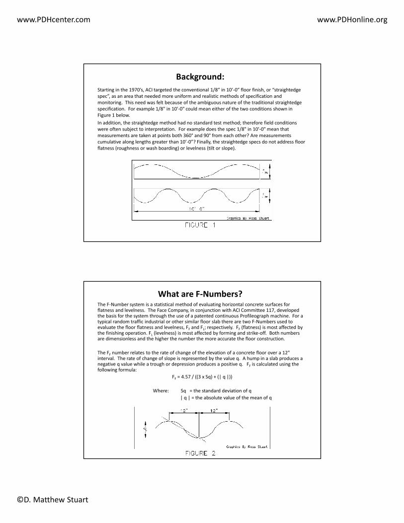
Background:
Starting in the 1970’s, ACI targeted the conventional 1/8” in 10’-0” floor finish, or “straightedge
spec”, as an area that needed more uniform and realistic methods of specification and
monitoring. This need was felt because of the ambiguous nature of the traditional straightedge
specification. For example 1/8" in 10'-0" could mean either of the two conditions shown in
Figure 1 below.
In addition, the straightedge method had no standard test method; therefore field conditions
were often subject to interpretation. For example does the spec 1/8" in 10'-0" mean that
measurements are taken at points both 360° and 90° from each other? Are measurements
cumulative along lengths greater than 10’-0”? Finally, the straightedge specs do not address floor
flatness (roughness or wash boarding) or levelness (tilt or slope).
What are F-Numbers?The F-Number system is a statistical method of evaluating horizontal concrete surfaces for flatness and levelness. The Face Company, in conjunction with ACI Committee 117, developed the basis for the system through the use of a patented continuous Profileograph machine. For a typical random traffic industrial or other similar floor slab there are two F-Numbers used to evaluate the floor flatness and levelness, FF and FL; respectively. FF (flatness) is most affected by the finishing operation. FL (levelness) is most affected by forming and strike-off. Both numbers are dimensionless and the higher the number the more accurate the floor construction.
The FF number relates to the rate of change of the elevation of a concrete floor over a 12" interval. The rate of change of slope is represented by the value q. A hump in a slab produces a negative q value while a trough or depression produces a positive q. FF is calculated using the following formula:
FF = 4.57 / ((3 x Sq) + (| q |))
Where: Sq = the standard deviation of q
| q | = the absolute value of the mean of q

www.PDHcenter.com www.PDHonline.org
©D. Matthew Stuart
The FL number relates to the general floor slope of a concrete slab from an assumed datum
elevation. The difference in elevation of two points which are 10'-0" apart are measured as the value
z. FL is calculated using the following formula:
FL = 12.5 / ((3 x Sz) + (| z |))
Where: Sz = the standard deviation of z
| z | = the absolute value of the mean of z
For defined traffic industrial floor slabs, such as very-narrow-aisle warehouses where forklifts
travel the same path, an Fmin numerical system is used. Fmin is not calculated like FF or FL. Fmin is
actually a direct measurement of the floor surface in the wheel path of the forklift for which the
defined traffic area is designed. An Fmin100 specification is a baseline number corresponding to a
flatness tolerance of 1/8" in 10'-0". An Fmin50 specification corresponds to a flatness tolerance of
1/8" in 5'-0", or 1/4" in 10'-0".
Source: T2 Storage Solutions

www.PDHcenter.com www.PDHonline.org
©D. Matthew Stuart
How are F-Numbers Specified?ACI 117 is the industry standard for the use of the F-Number system and establishes the F-Numbers
of different types of floors as well as the definitions of acceptable variances. ACI 302 also provides
guidelines for the placing and finishing of concrete floor slab construction for the F-Number
system. ASTM E 1155 is the basis of the standard test method for the FF and FL number system.
One of the most important aspects of establishing F-Numbers is to not over specify beyond that
which is really required for a given project. This is because an increase in required floor quality will
almost always result in higher costs. One of the best methods for determining the most
appropriate criteria to specify for a project is to measure existing floors that are performing
satisfactorily. Specifications should state the performance criteria only and not specify the method
of obtaining the required tolerances. This is recommended because the quality of work varies from
finishing crew to finishing crew for any given standard technique used in the field.
Source: Warehouse & Logistics News
FF and FL are typically specified for both overall and minimum local values. This helps prevent the
acceptance of isolated local areas of low quality construction due to it being averaged in with
other areas of the slab that surpass the minimum requirements. The specified overall values
describe the flatness and levelness values that must be achieved when all measured values on a
given test surface are combined. The minimum local values describe the flatness and levelness
values below which repair or replacement is required within the affected area. The general rule
of thumb is that the local area minimum must be within 2/3 of the specified overall value. On
elevated slabs the FL levelness tolerance does not apply because of the deflection of the overall
framing system and should therefore not be specified. Only FF numbers should be specified for
elevated slabs.
Source: TTL Inc.

www.PDHcenter.com www.PDHonline.org
©D. Matthew Stuart
Lift and forktruck manufactures publish recommended Fmin floor tolerances to assure the proper
operation of their equipment. The higher the number the flatter and more level the floor
requirement is. Fmin100 is typically referred to as a "Superflat" floor requirement. Producing an
Fmin100 tolerance in any direction on a floor is comparable to producing a floor surface meeting
FF140 and FL100 tolerances.
Source: Creamer Media
An additional ASTM specification, E 1486 can be used to determine the deviation from a 10-foot
straightedge for both random and defined traffic floors in order to determine the "Waviness
Index". In addition this specification provides defined wheel track equations for specifying
elevation differences and change in elevation transversely between left and right wheel tracks
and longitudinally from front to rear axle , therefore this spec can be used as a standard for
evaluating Fmin floor tolerances.
Source: Dynamic Floor Specialists

www.PDHcenter.com www.PDHonline.org
©D. Matthew Stuart
The following table can be used as a guideline for specifying F-Numbers for various floor profile
categories:
Recommended F-Numbers for Various Floor Profile Categories
Floor Profile Category Random Traffic Floors Defined Traffic
FloorsSpecified Overall Value Minimum Local Value
FF FL FF FL Fmin
Conventional
(using bullfloat)
19 13 13 10 19
Conventional
(using highway straightedge)
25 17 13 10 25
Good 38 25 19 13 38
Flat 50 33 25 17 50
Very Flat 75 50 38 25 75
Superflat 100 66 50 33 100
Ultraflat 150 100 75 50 150
In addition, although there is no direct equivalence between F-Numbers and traditional straightedge
specifications the following table provides an approximate correlation between straightedge
measurements and FF Numbers.
Approximate Equivalence of FF Numbers and Straightedge Measurements
F-Number Gap Under 10’-0” Straightedge
12 1/2”
20 5/16”
25 1/4”
32 3/16”
50 1/8”

www.PDHcenter.com www.PDHonline.org
©D. Matthew Stuart
How are F-Numbers Measured?Floor flatness and levelness tests should be conducted anywhere from within 16 to 72 hours after
completion of the final troweling operation, depending on the project type and requirements. As
it is typically not practical to obtain acceptable local values across construction joints it is
recommended that these areas be omitted from consideration for comparison to the specified
minimum local value. It should also be noted that it is entirely possible that the floor can be
within specified tolerances during the initial testing process but become out of spec prior to
actual use because of slab cracking, curling or sub-grade settlement.
ASTM E1155 is the governing specification for the testing procedures used to determine floor
flatness and levelness for random traffic floors. This standard allows for numerous techniques for
gathering the required date including levels, inclinometers, Profilometers and other means. One
of the most often used pieces of equipment for these measurements is the Dipstick floor profiler,
an apparatus that can field measure both floor flatness and levelness. This equipment can be
programmed to measure floor slabs on slopes also.
Source: Concrete Bindings LTD
For defined traffic floors such as rack aisleways where the wheel traffic occurs in the same
location for all operations, instead of random sampling, traffic paths are directly measured using
a continuous recording floor Profilometer configured to run in exactly the same specified wheel
tracks as the forktrucks. The results of the measurements taken do not produce F-Numbers, but
instead simply confirm compliance with the minimum requirements specified. Changes in
elevation and rate of change are confirmed in both the longitudinal and transverse direction of
the wheel travel. The record of measurements indicates the exact location of any areas that are
not in compliance.
Source: CoGri Korea Company

www.PDHcenter.com www.PDHonline.org
©D. Matthew Stuart
Concrete Slab Finishing Specification Example:
The following is an example of a performance-based specification for concrete finishing as it relates to the F-Number system. Red text that is located within brackets indicates alternate or optional items depending on the nature of the project:
A. Concrete Finish: Concrete finish floors shall have a [hard steel troweled finish; light broom finish] unless indicated otherwise on the drawings. Place, strike off, consolidate, level and float to the proper elevation. Troweling shall begin after surface has received a float finish. The slab drying must proceed naturally and must not be hastened by the dusting on of dry cement or sand. Lightly tool all edges at construction joints and exercise care that slab edges are not depressed along bulkheads during finishing operations, particularly hand troweling. Exterior slabs, sidewalks, pads and ramps shall have a light broom finish unless indicated otherwise on the drawings. Provide standard trowel finish at all sub-slabs.
1. Random traffic floors shall conform to the following surface profile tolerances:
a. Floor Designation: All floor areas not specified to be part of the "defined traffic floor" should be part of the "random traffic floor". Any floor slab comprising part of the random traffic floor shall be designated a “random traffic slab".
b. Flatness and Levelness Tolerances: The random traffic floor shall conform to the following surface profile tolerances:
Floor Flatness Number: FF
Specified Overall Value = [35]
Minimum Local Value = [24]
Floor Levelness Number: FL
Specified Overall Value = [25]
Minimum Local Value = [18]c. Floor Tolerance Measurements: FF and FL tolerances shall be tested in accordance with ASTM E 1155. Actual overall F-numbers shall be calculated using
the inferior / superior area method.d. Timeliness of Floor Profile Tests & Reports: All floor tolerance measurements shall be made within [48] hours after slab installation. In all cases, tolerance
measurements shall precede the removal of shores and forms. Results of all floor profile tests (including a running tabulation of the overall FF and FLvalues for all of the random traffic slabs installed to date) shall be provided to the Contractor within [72] hours after each slab installation.
e. Remedy for Out-of-Tolerance Work: For the purposes of flatness and levelness control, minimum floor section boundaries shall coincide with the control joints. Profile test compliance requirements apply to that time period specified above only. The Contractor shall remedy any floor section measuring below either the minimum local FF number, or FL number. Any floor section measuring at or above both the minimum local FF number and the minimum local FL number shall be accepted. If the actual overall FF number or the actual overall FL number for the entire random-traffic floor installation measures less than its specified value, then the Contractor shall undertake the remedial measures that have been approved by the Engineer.
2. Defined traffic floors shall conform to the following surface profile tolerances:
a. Floor Designation: All floor areas specified as “defined traffic floor" include only the [rack aisleways].
b. Flatness and Levelness Tolerances: The defined traffic floor shall conform to the following surface profile tolerances: Fmin = [75]
c. Floor Tolerance Measurements: Fmin tolerances shall be tested in accordance with ASTM E 1486.
d. Timeliness of Floor Profile Tests & Reports: All floor tolerance measurements shall be made by the contractor within [24] hours after slab installation and before saw cutting of control joints. In all cases, tolerance measurements shall precede the removal of shores and forms. Results of all floor profile tests including a running tabulation of the overall Fmin values for all of the defined-traffic slabs installed to date shall be provided to the Contractor within [48] hours after each slab installation.
e. Remedy for Out-of-Tolerance Work: For the purposes of flatness and levelness control, minimum floor section boundaries shall coincide with the construction joints. Profile test compliance requirements apply to that time period specified above only. The Contractor shall remedy any floor section measuring below the Fmin number, in accordance with the recommendations of the Engineer. Any floor section measuring at or above the Fmin number shall be accepted. If the actual overall Fmin number for the entire defined-traffic floor installation measures less than its specified value, then the Contractor shall undertake the remedial measures that have been approved by the Engineer.
3. If a portion of a floor does not meet the specified F-number the following remedies are recommended:
a. Local value is out of spec - grind or replace floor.
b. Overall value is out of spec - the contractor shall pay the owner per square foot for portion of floor not meeting F-number spec. This can be done by specifying a figure in the project specifications in conjunction with the square footage obtained from reading taken in the field.