7. valve clearance - seccs legacy/service manual/engine section/on-car...7) measure #1 cylinder...
TRANSCRIPT

S2M0242
Oil pressure:98 kPa (1.0 kg/cm 2,14 psi) or more at 800rpm294 kPa (3.0 kg/cm 2, 43 psi) or more at5,000 rpm
CAUTION:I If oil pressure is out of specification, checkoil pump, oil filter and lubrication line. <Ref. to2-4 [K100].>I If oil pressure warning light is turned ON andoil pressure is in specification, replace oil pres-sure switch. <Ref. to 2-4 [W3A0].>
NOTE:The specified data is based on an engine oil tem-perature of 80°C (176°F).
8) After measuring oil pressure, install oil pressureswitch.
Tightening torque:25±3 N·m (2.5±0.3 kg-m, 18.1 ±2.2 ft-lb)
9) Install generator and V-belt in the reverse orderof removal, and adjust the V-belt deflection.
7. Valve ClearanceA: INSPECTION1. 2200 cc MODELCAUTION:Inspection and adjustment of valve clearanceshould be performed while engine is cold.
1) Set the vehicle onto the lift.2) Disconnect battery ground cable.
B2M1723
3) Remove engine coolant reservoir tank. <Ref. to2-5 [W9A0].>
S2M0028
4) Remove timing belt cover (LH).
B2M2031
5) Remove rocker cover.I When inspecting #1 and #3 cylinders:
I Low emission vehicle:
7
[W7A1] 2-2SERVICE PROCEDURE7. Valve Clearance

(1) Remove air intake duct A and B as a unit.
B2M2012
(2) Remove resonator chamber.
B2M2013
(3) Disconnect spark plug cords from sparkplugs (#1 and #3 cylinders).
B2M2014
(4) Disconnect blow-by hose from rockercover (RH).
B2M2015
(5) Lift-up the vehicle.(6) Remove under cover (RH).(7) Place suitable container under thevehicle.
(8) Lower the vehicle.(9) Remove the timing belt cover (RH) bolt.
B2M2016
(10) Remove rocker cover bolts, thenremove rocker cover (RH).
B2M2017
I Except low emission vehicle:(1) Disconnect connector from mass air flowsensor.
B2M2018
(2) Loosen clamp which connects air intakeduct and air intake chamber.
B2M2019
8
2-2 [W7A1] SERVICE PROCEDURE7. Valve Clearance

(3) Remove clips of air cleaner upper cover.(4) Remove air intake duct and air cleanerupper cover as a unit.
B2M2020
(5) Remove air cleaner element.(6) Remive air cleaner lower case.
S2M0179
(7) Disconnect spark plug cords from sparkplugs (#1 and #3 cylinders).
B2M2014
(8) Disconnect blow-by hose from rockercover (RH).
B2M2015
(9) Lift-up the vehicle.
(10) Remove under cover (RH).(11) Place suitable container under thevehicle.(12) Lower the vehicle.(13) Remove the timing belt cover (RH) bolt.
B2M2016
(14) Remove rocker cover bolts, thenremove rocker cover (RH).
B2M2017
I When inspecting #2 and #4 cylinders:(1) Disconnect battery cables, and thenremove battery and battery carrier.(2) Disconnect front window washer motorconnector.(3) Disconnect rear gate glass washer motorconnector. (Wagon only)
S2M0546
9
[W7A1] 2-2SERVICE PROCEDURE7. Valve Clearance

(4) Disconnect rear gate glass washer hosefrom washer motor, then plug connectionwith a suitable cap. (Wagon only)(5) Remove the two bolts which hold washertank, then secure the tank away from work-ing area.
B2M2023
(6) Disconnect spark plug cords from sparkplugs (#2 and #4 cylinders).
B2M2024
(7) Disconnect blow-by hose form rockercover (LH).
B2M2025
(8) Lift-up the vehicle.(9) Remove under cover (LH).(10) Place suitable container under thevehicle.(11) Remove rocker cover bolts, thenremove rocker cover (LH).
B2M2026
6) Set #1 cylinder piston to top dead center ofcompression stroke by rotating crankshaft pulleyclockwise.
NOTE:When arrow mark on camshaft sprocket (LH)comes exactly to the top, #1 cylinder piston isbrought to the top dead center of the compressionstroke.
B2M2027A
10
2-2 [W7A1] SERVICE PROCEDURE7. Valve Clearance

7) Measure #1 cylinder valve clearance by usingthickness gauge.
CAUTION:I Insert the thickness gauge in at as horizon-tal a direction as a possible with respect to thevalve stem end face.I Measure exhaust valve clearances while lift-ing-up the vehicle.
Valve clearance:Intake: 0.20 ±0.02 mm (0.0079±0.0008 in)Exhaust: 0.25 ±0.02 mm (0.0098±0.0008 in)
B2M2028A
8) If necessary, adjust the valve clearance. <Ref.to 2-2 [W7B1].>9) Similar to measurement procedures used for #1cylinder, measure #2, #3 and #4 cylinder valveclearances.
NOTE:I Be sure to set cylinder pistons to their respectivetop dead centers on the compression stroke beforemeasuring valve clearances.I To set #3, #2 and #4 cylinder pistons to their topdead centers on the compression stroke, turncrankshaft pulley clockwise 90° at a time startingwith arrow mark on left- hand camshaft sprocketfacing up.
B2M2029A
10) After inspection, install the related parts in thereverse order of removal.
2. 2500 cc MODELCAUTION:Inspection and adjustment of valve clearanceshould be performed while engine is cold.
1) Set the vehicle onto the lift.2) Disconnect battery ground cable.3) Remove canister (Taiwan spec. vehicles only).4) Remove two bolts on the upper side whichsecure timing belt cover (RH).5) Lift-up the vehicle.6) Remove under cover (RH).7) Remove canister bracket (Taiwan spec.vehicles only).8) Loosen remaining bolt on under side whichsecures timing belt cover (RH), then remove beltcover.9) Lower the vehicle.10) Remove rocker cover.I When inspecting #1 and #3 cylinders;
(1) Disconnect connector from mass air flowsensor.
B2M1225A
(2) Loosen clamp which connects air intakeduct to air intake chamber.
B2M1226A
(3) Remove the two clips from air cleaner uppercover.
CAUTION:Before installing air cleaner upper cover, alignhole(s) with protruding portions of air cleanerlower case, then secure upper cover.
(4) Disconnect blow-by hose from air intakeduct.
11
[W7A2] 2-2SERVICE PROCEDURE7. Valve Clearance

(5) Remove air intake duct and air cleanerupper cover as a unit.
B2M1227
(6) Remove air cleaner element.(7) Remove air cleaner lower case.
S2M0179
(8) Disconnect spark plug cords from sparkplugs (#1 and #3 cylinders).(9) Place suitable container under the vehicle.(10) Disconnect PCV hose from rocker cover(RH).(11) Remove bolts, then remove rocker cover(RH).
I When inspecting # 2 and #4 cylinders;(1) Disconnect battery cables, and thenremove battery and battery carrier.(2) Disconnect washer motor connectors.(3) Disconnect washer hoses from washermotors, then plug connections with suitablecaps.(4) Remove washer tank.(5) Disconnect spark plug cords from sparkplugs (#2 and #4 cylinders).(6) Remove under cover (LH).(7) Place suitable container under the vehicle.(8) Disconnect PCV hose from rocker cover(LH).(9) Remove bolts, then remove rocker cover(LH).
11) Turn crankshaft pulley clockwise until arrowmark on camshaft sprocket is set to position shownin figure.
B2M1233A
12) Measure #1 cylinder intake valve and #3 cyl-inder exhaust valve clearances by using thicknessgauge.
CAUTION:I Insert the thickness gauge in as horizontal adirection as possible with respect to the shim.I Measure exhaust valve clearances while lift-ing-up the vehicle.
Valve clearance:Intake: 0.20 ±0.02 mm (0.0079±0.0008 in)Exhaust: 0.25 ±0.02 mm (0.0098±0.0008 in)
B2M1234A
13) If necessary, adjust the valve clearance. <Ref.to 2-2 [W7B2].>14) Further turn crankshaft pulley clockwise.Using the same procedures as in step 12) above,measure valve clearances.
12
2-2 [W7A2] SERVICE PROCEDURE7. Valve Clearance
(1) Set arrow mark on camshaft sprocket toposition shown in figure, and measure #2 cylin-der exhaust valve and #3 cylinder intake valveclearances.
B2M1235A
(2) Set arrow mark on camshaft sprocket toposition shown in figure, and measure #2 cylin-der intake valve and #4 cylinder exhaust valveclearances.
B2M1236A
(3) Set arrow mark on camshaft sprocket toposition shown in figure, and measure #1 cylin-der exhaust valve and #4 cylinder intake valveclearances.
B2M1237A
15) After inspection, install the related parts in thereverse order of removal.
B: ADJUSTMENT1. 2200 cc MODELCAUTION:Adjustment of valve clearance should be per-formed while engine is cold.
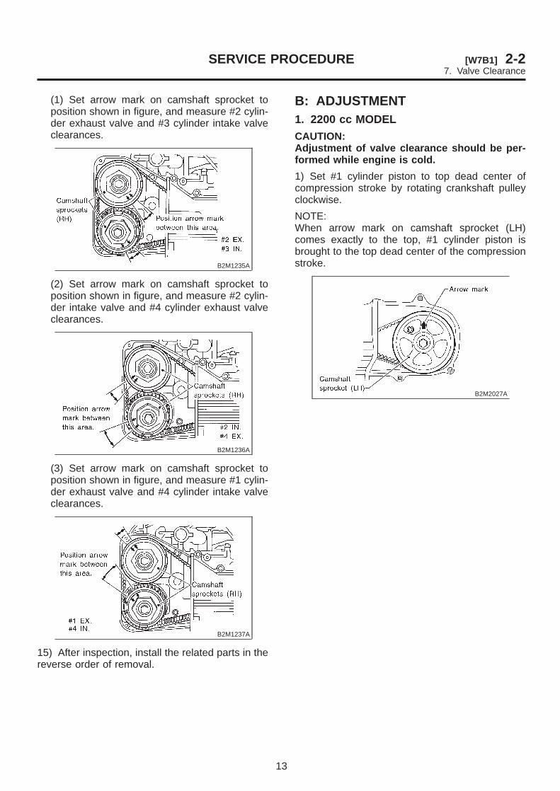
1) Set #1 cylinder piston to top dead center ofcompression stroke by rotating crankshaft pulleyclockwise.
NOTE:When arrow mark on camshaft sprocket (LH)comes exactly to the top, #1 cylinder piston isbrought to the top dead center of the compressionstroke.
B2M2027A
13
[W7B1] 2-2SERVICE PROCEDURE7. Valve Clearance

2) Adjust the #1 cylinder valve clearance.(1) Loosen the valve rocker nut and screw.(2) Place suitable thickness gauge.(3) While noting valve clearance, tighten valverocker adjust screw.(4) When specified valve clearance is obtained,tighten valve rocker nut.
Tightening torque:10±1 N·m (1.0±0.1 kg-m, 7.2 ±0.7 ft-lb)
CAUTION:I Insert the thickness gauge in at as horizon-tal a direction as possible with respect to thevalve stem end face.I Adjust exhaust valve clearances while lift-ing-up the vehicle.
Valve clearance:Intake: 0.20 ±0.02 mm (0.0079±0.0008 in)Exhaust: 0.25 ±0.02 mm (0.0098±0.0008 in)
B2M2030A
(a) Thickness gauge(b) Valve rocker nut(c) Valve rocker screw
3) Ensure that valve clearances are within speci-fications.4) Turn crankshaft two complete rotations until #1cylinder piston is again set to top dead center oncompression stroke.5) Ensure that valve clearances are within speci-fications. If necessary, re-adjust valve clearances.
6) Similar to adjustment procedures used for #1cylinder, adjust #2, #3 and #4 cylinder valve clear-ances.
NOTE:I Be sure to set cylinder pistons to their respectivetop dead centers on the compression stroke beforeadjusting valve clearances.I To set #3, #2 and #4 cylinder pistons to their topdead centers on the compression stroke, turncrankshaft pulley clockwise 90° at a time startingwith arrow mark on left-hand camshaft sprocketfacing up.
B2M2029A
2. 2500 cc MODELCAUTION:Adjustment of valve clearance should be per-formed while engine is cold.
1) Measure all valve clearances. <Ref. to 2-2[W7A2].>
NOTE:Record each valve clearance after it has beenmeasured.
B2M1234A
14
2-2 [W7B2] SERVICE PROCEDURE7. Valve Clearance

2) Remove shim of intake side.(1) Prepare the ST.
ST 498187100 SHIM REPLACER KIT
H1H0491
(2) Rotate the notch of the valve lifter outwardby 45°.
H2M1771A
(3) Set REPLACER No. 1 (A) to intake cam-shaft.
H2M1772B
(4) Set REPLACER No. 2 (B).
H2M1773B
(5) Set REPLACER No. 3 (C) to hole ofREPLACER No. 1.
H2M1774B
(6) Rotate REPLACER No. 3 (C) untilREPLACER No. 2 (B) pushes away valve lifter.
H2M1775B
(7) Insert tweezers into the notch of the valvelifter, and take the shim out.
H2M1776A
3) Remove shim of exhaust side.(1) Prepare the ST.
ST 498187100 SHIM REPLACER KIT
H1H0491
15
[W7B2] 2-2SERVICE PROCEDURE7. Valve Clearance

(2) Rotate the notch of the valve lifter outwardby 45°.
H2M1777A
(3) Set REPLACER No. 1 (A) to exhaust cam-shaft.
H2M1778B
(4) Set REPLACER No. 2 (B).
H2M1779B
(5) Set REPLACER No. 3 (C) to hole ofREPLACER No. 1.
H2M1780B
(6) Rotate REPLACER No. 3 until REPLACERNo. 2 pushes away valve lifter.
H2M1781
(7) Insert tweezers into the notch of the valvelifter, and take the shim out.
NOTE:By using a magnet, the shim can be taken outwithout dropping it.
H2M1782A
4) Measure thickness of shim with micrometer.
B2M1240A
16
2-2 [W7B2] SERVICE PROCEDURE7. Valve Clearance

5) Select a shim of suitable thickness using measured valve clearance and shim thickness, using the fol-lowing table.
Intake valve (mm): S = (V + T) − 0.20Exhaust valve (mm): S = (V + T) − 0.25
S: Shim thickness to be usedV: Measured valve clearanceT: Shim thickness required
Part No. Thickness mm (in) Part No. Thickness mm (in)13218AC230 2.22 (0.0874) 13218AC480 2.52 (0.0992)13218AE000 2.23 (0.0878) 13218AC490 2.53 (0.0996)13218AC240 2.24 (0.0882) 13218AC500 2.54 (0.1000)13218AE010 2.25 (0.0886) 13218AC510 2.55 (0.1004)13218AC250 2.26 (0.0890) 13218AC520 2.56 (0.1008)13218AE020 2.27 (0.0894) 13218AC530 2.57 (0.1012)13218AC260 2.28 (0.0898) 13218AC540 2.58 (0.1016)13218AE030 2.29 (0.0902) 13218AC550 2.59 (0.1020)13218AC270 2.30 (0.0906) 13218AC560 2.60 (0.1024)13218AE040 2.31 (0.0909) 13218AC570 2.61 (0.1028)13218AC280 2.32 (0.0913) 13218AC580 2.62 (0.1031)13218AC290 2.33 (0.0917) 13218AC590 2.63 (0.1035)13218AC300 2.34 (0.0921) 13218AC600 2.64 (0.1039)13218AC310 2.35 (0.0925) 13218AC610 2.65 (0.1043)13218AC320 2.36 (0.0929) 13218AC620 2.66 (0.1047)13218AC330 2.37 (0.0933) 13218AC630 2.67 (0.1051)13218AC340 2.38 (0.0937) 13218AC640 2.68 (0.1055)13218AC350 2.39 (0.0941) 13218AC650 2.69 (0.1059)13218AC360 2.40 (0.0945) 13218AC660 2.70 (0.1063)13218AC370 2.41 (0.0949) 13218AE050 2.71 (0.1067)13218AC380 2.42 (0.0953) 13218AC670 2.72 (0.1071)13218AC390 2.43 (0.0957) 13218AE060 2.73 (0.1075)13218AC400 2.44 (0.0961) 13218AC680 2.74 (0.1079)13218AC410 2.45 (0.0965) 13218AE070 2.75 (0.1083)13218AC420 2.46 (0.0969) 13218AC690 2.76 (0.1087)13218AC430 2.47 (0.0972) 13218AE080 2.77 (0.1091)13218AC440 2.48 (0.0976) 13218AC700 2.78 (0.1094)13218AC450 2.49 (0.0980) 13218AE090 2.79 (0.1098)13218AC460 2.50 (0.0984) 13218AC710 2.80 (0.1102)13218AC470 2.51 (0.0988) 13218AE100 2.81 (0.1106)
6) Set suitable shim selected in one step before,to valve lifter.
17
[W7B2] 2-2SERVICE PROCEDURE7. Valve Clearance

7) Turn crankshaft pulley clockwise until arrowmark on camshaft sprocket is set to position shownin figure.
B2M1233A
8) Ensure that #1 cylinder intake valve and #3 cyl-inder exhaust valve are adjusted to specifications.
CAUTION:I Insert the thickness gauge in as horizontal adirection as possible with respect to the shim.I Adjust exhaust valve clearances while lift-ing-up the vehicle.
Valve clearance:Intake: 0.20 ±0.02 mm (0.0079±0.0008 in)Exhaust: 0.25 ±0.02 mm (0.0098±0.0008 in)
B2M1234A
9) Turn crankshaft two complete rotations. Checkagain to ensure that #1 cylinder intake valve and#3 cylinder exhaust valve clearances are withinspecifications. If necessary, re-adjust valve clear-ances.10) Further turn crankshaft pulley clockwise.Using the same procedures as in two steps before,measure valve clearances.
(1) Set arrow mark on camshaft sprocket toposition shown in figure, and check #2 cylinderexhaust valve and #3 cylinder intake valveclearances.
B2M1235A
(2) Set arrow mark on camshaft sprocket toposition shown in figure, and check #2 cylinderintake valve and #4 cylinder exhaust valveclearances.
B2M1236A
(3) Set arrow mark on camshaft sprocket toposition shown in figure, and check #1 cylinderexhaust valve and #4 cylinder intake valveclearances.
B2M1237A
18
2-2 [W7B2] SERVICE PROCEDURE7. Valve Clearance