pbl summary 23-03-07 - cern · psbooster = proton synchrotron booster ... the motion of particle...
TRANSCRIPT
Elias Métral, PBL course: summary, Lund, Sweden, 19-23/03/07 1/40
PBL SCENARIO ON ACCELERATORS:SUMMARY
CERN accelerators and CERN Control CentreMachine luminosityTransverse beam dynamics + space chargeLongitudinal beam dynamicsSolution of the transverse problemSolution of the longitudinal problemSynchrotron radiation
EliasElias MMéétraltral
[email protected]@cern.chTel.: 72560 or 164809Tel.: 72560 or 164809
Elias Métral, PBL course: summary, Lund, Sweden, 19-23/03/07 2/40
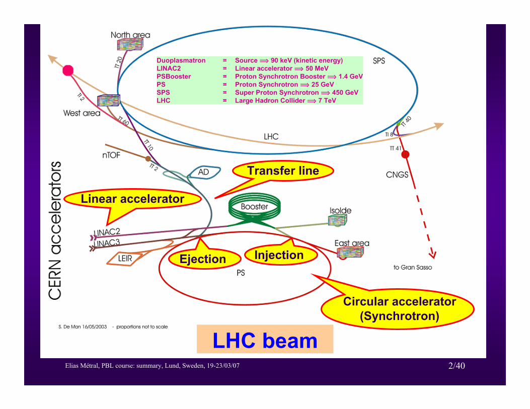
LHC beam
Linear accelerator
Circular accelerator (Synchrotron)
Transfer line
InjectionEjection
Duoplasmatron = Source î 90 keV (kinetic energy)LINAC2 = Linear accelerator î 50 MeVPSBooster = Proton Synchrotron Booster î 1.4 GeVPS = Proton Synchrotron î 25 GeVSPS = Super Proton Synchrotron î 450 GeVLHC = Large Hadron Collider î 7 TeV
Elias Métral, PBL course: summary, Lund, Sweden, 19-23/03/07 3/40
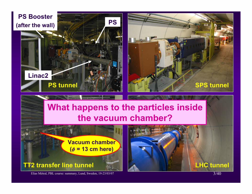
SPS tunnel
LHC tunnelTT2 transfer line tunnel
PS tunnelLinac2
PS Booster(after the wall) PS
Vacuum chamber (f = 13 cm here)
What happens to the particles inside the vacuum chamber?

Elias Métral, PBL course: summary, Lund, Sweden, 19-23/03/07 4/40
CERN Control Centre (CCC)
Island for the PS complex
Island for the Technical Infrastructure + LHC
cryogenics
Island for the LHC
Island for the SPS
ENTRANCE
Elias Métral, PBL course: summary, Lund, Sweden, 19-23/03/07 5/40
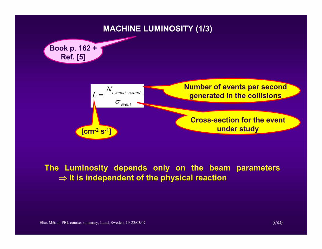
MACHINE LUMINOSITY (1/3)
event
ondeventsNLσ
sec/=Number of events per second
generated in the collisions
Cross-section for the event under study
The Luminosity depends only on the beam parameters ⇒ It is independent of the physical reaction
[cm-2 s-1]
Book p. 162 + Ref. [5]
Elias Métral, PBL course: summary, Lund, Sweden, 19-23/03/07 6/40
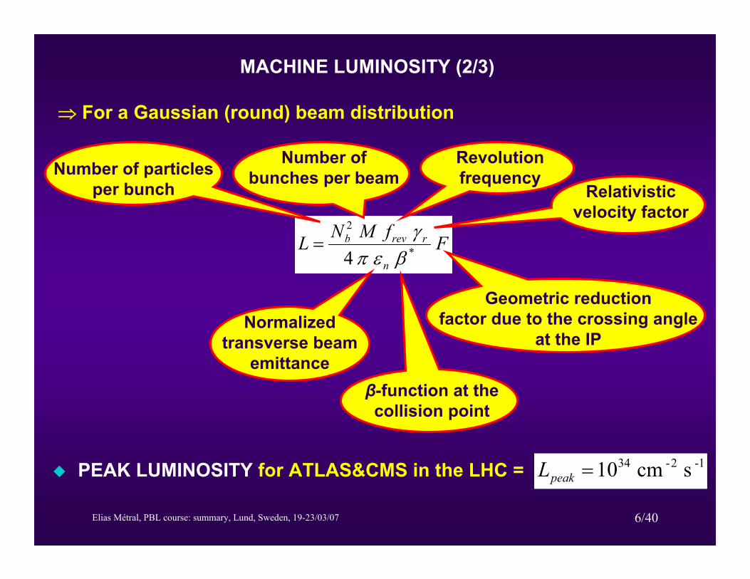
⇒ For a Gaussian (round) beam distribution
FfMNLn
rrevb*
2
4 βεπγ
=
Number of particles per bunch
Number of bunches per beam
Revolution frequency
Relativistic velocity factor
Normalized transverse beam
emittanceβ-function at the collision point
Geometric reduction factor due to the crossing angle
at the IP
PEAK LUMINOSITY for ATLAS&CMS in the LHC = 1-2-34 scm10=peakL
MACHINE LUMINOSITY (2/3)
Elias Métral, PBL course: summary, Lund, Sweden, 19-23/03/07 7/40
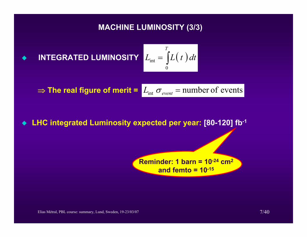
INTEGRATED LUMINOSITY ( ) dttLLT
∫=0
int
⇒ The real figure of merit = events ofnumber int =eventL σ
LHC integrated Luminosity expected per year: [80-120] fb-1
Reminder: 1 barn = 10-24 cm2
and femto = 10-15
MACHINE LUMINOSITY (3/3)
Elias Métral, PBL course: summary, Lund, Sweden, 19-23/03/07 8/40
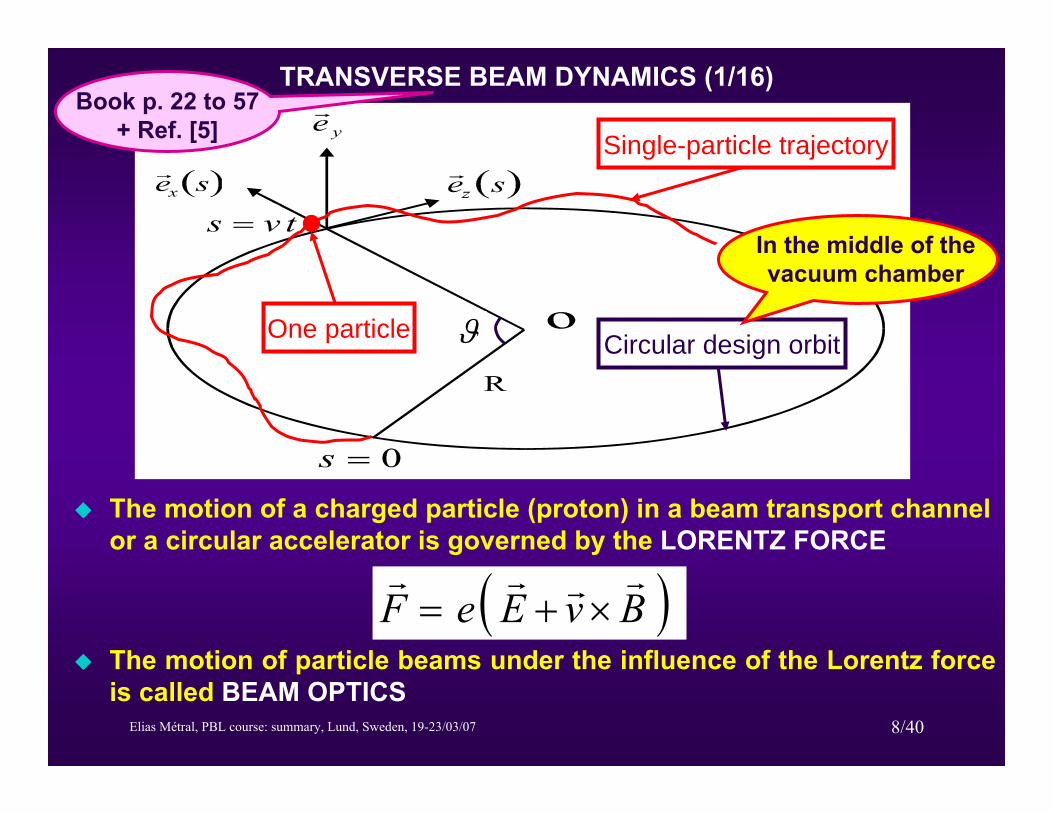
TRANSVERSE BEAM DYNAMICS (1/16)
Single-particle trajectory
Circular design orbitOne particle ϑ
In the middle of the vacuum chamber
The motion of a charged particle (proton) in a beam transport channel or a circular accelerator is governed by the LORENTZ FORCE
( )BvEeFrrrr
×+=The motion of particle beams under the influence of the Lorentz force is called BEAM OPTICS
Book p. 22 to 57+ Ref. [5]
Elias Métral, PBL course: summary, Lund, Sweden, 19-23/03/07 9/40
TRANSVERSE BEAM DYNAMICS (2/16)
The Lorentz force is applied as a
BENDING FORCE (using DIPOLES) to guide the particles along a predefined ideal path, the DESIGN ORBIT, on which – ideally – all particles should move
FOCUSING FORCE (using QUADRUPOLES) to confine the particles in the vicinity of the ideal path, from which most particles will unavoidably deviate
LATTICE = Arrangement of magnets along the design orbit
The ACCELERATOR DESIGN is made considering the beam as a collection of non-interacting single particles

Elias Métral, PBL course: summary, Lund, Sweden, 19-23/03/07 10/40
TRANSVERSE BEAM DYNAMICS (3/16)
DIPOLE = Bending magnet
BEAM RIGIDITY [ ] [ ]c/GeV3356.3mT 0pB =ρ
Magnetic field Beam momentumCurvature radius of the dipoles
⇒ A particle, with a constant energy, describes a circle in equilibrium between the centripetal magnetic force and the centrifugal force
N-pole
S-pole
Bg
gx
yBend
magnetDesign
orbit
F
vs
B
( )sρ
Constant force in xand 0 force in y
Beam

Elias Métral, PBL course: summary, Lund, Sweden, 19-23/03/07 11/40
TRANSVERSE BEAM DYNAMICS (4/16)
QUADRUPOLE = Focusing magnet
In x (and Defocusing in y) ⇒ F-type. Permuting
the N- and S- poles gives a D-type
Linear force in x&y
( ) ( ) 0=+′′ sxKsx⇒ : Equation of a harmonic oscillator
From this equation, one can already anticipate the elliptical shapeof the particle trajectory in the phase space (x, x’) by integration
( ) ( ) Constant22 =+′ sxKsx
N-poleS-pole
S-poleN-pole
x
y
Beam
Beam
Elias Métral, PBL course: summary, Lund, Sweden, 19-23/03/07 12/40
TRANSVERSE BEAM DYNAMICS (5/16)
Along the accelerator K is not constant and depends on s (and is periodic) ⇒ The equation of motion is then called HILL’S EQUATION
The solution of the Hill’s equation is a pseudo-harmonic oscillation with varying amplitude and frequency called BETATRON OSCILLATION
An invariant, i.e. a constant of motion, (called COURANT-SNYDER INVARIANT) can be found from the solution of the Hill’s equation
⇒ Equation of an ellipse (motion for one particle) in the phase space plane (x, x’), with area π a2
Elias Métral, PBL course: summary, Lund, Sweden, 19-23/03/07 13/40
TRANSVERSE BEAM DYNAMICS (6/16)
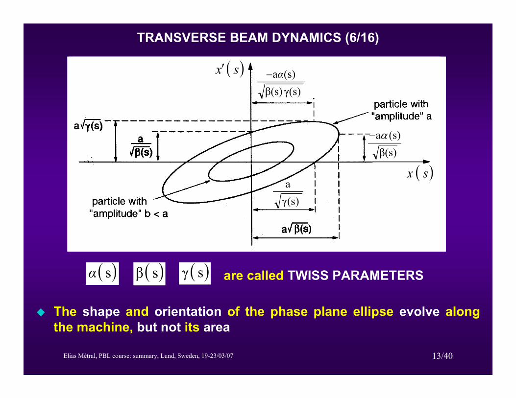
The shape and orientation of the phase plane ellipse evolve along the machine, but not its area
are called TWISS PARAMETERS( )sα ( )sβ ( )sγ
( )sx
( )sx′
Courtesy M. Martini
)s(γa
β(s)(s)aα−
( )sx′γ(s)β(s)(s)aα−
Elias Métral, PBL course: summary, Lund, Sweden, 19-23/03/07 14/40
TRANSVERSE BEAM DYNAMICS (7/16)
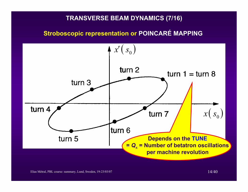
Stroboscopic representation or POINCARÉ MAPPING
( )sx
( )sx′
( )0sx
( )0sx′
Depends on the TUNE= Qx = Number of betatron oscillations
per machine revolution
Elias Métral, PBL course: summary, Lund, Sweden, 19-23/03/07 15/40
TRANSVERSE BEAM DYNAMICS (8/16)
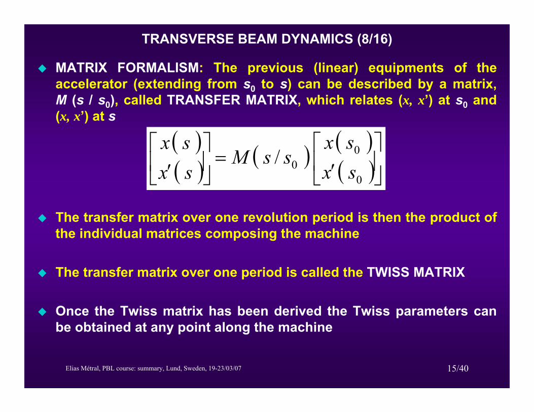
MATRIX FORMALISM: The previous (linear) equipments of the accelerator (extending from s0 to s) can be described by a matrix, M (s / s0), called TRANSFER MATRIX, which relates (x, x’) at s0 and (x, x’) at s
( )( ) ( ) ( )
( )⎥⎦⎤
⎢⎣
⎡′
=⎥⎦
⎤⎢⎣
⎡′ 0
00/
sxsx
ssMsxsx
The transfer matrix over one revolution period is then the product of the individual matrices composing the machine
The transfer matrix over one period is called the TWISS MATRIX
Once the Twiss matrix has been derived the Twiss parameters can be obtained at any point along the machine
Elias Métral, PBL course: summary, Lund, Sweden, 19-23/03/07 16/40
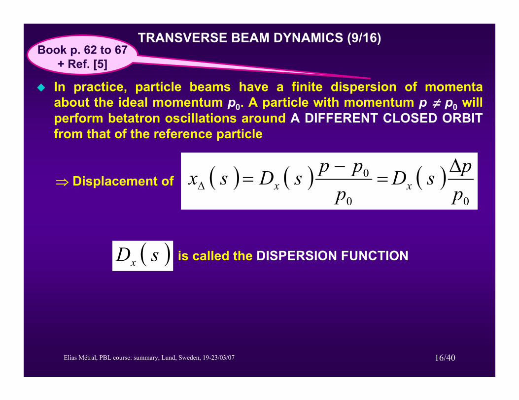
TRANSVERSE BEAM DYNAMICS (9/16)
In practice, particle beams have a finite dispersion of momentaabout the ideal momentum p0. A particle with momentum p π p0 will perform betatron oscillations around A DIFFERENT CLOSED ORBITfrom that of the reference particle
( ) ( ) ( )00
0
ppsD
pppsDsx xx
Δ=
−=Δ
is called the DISPERSION FUNCTION
⇒ Displacement of
( )sDx
Book p. 62 to 67+ Ref. [5]
Elias Métral, PBL course: summary, Lund, Sweden, 19-23/03/07 17/40
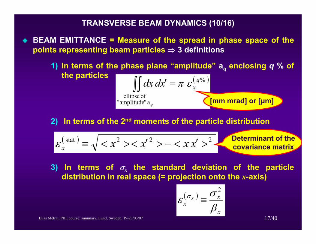
TRANSVERSE BEAM DYNAMICS (10/16)
BEAM EMITTANCE = Measure of the spread in phase space of the points representing beam particles ⇒ 3 definitions
1) In terms of the phase plane “amplitude” aq enclosing q % of the particles
2) In terms of the 2nd moments of the particle distribution
3) In terms of σx the standard deviation of the particle distribution in real space (= projection onto the x-axis)
( )%
a ""amplitude of ellipse
qx
q
xddx επ=′∫∫
( )
x
xx
x
βσε σ
2
≡
( ) 222stat >′<−>′<><≡ xxxxxε
[mm mrad] or [μm]
Determinant of the covariance matrix

Elias Métral, PBL course: summary, Lund, Sweden, 19-23/03/07 18/40
FAST WIRE SCANNER
-30 -20 -10 10 20 30POSITION @mmD
200
400
600
800
1000
HORIZONTAL PROFILE
Gaussianfit
( )
x
xx
x
βσε σ
2
≡
⇒ Measures the transverse beam profiles by detecting the particles scattered from a thin wire swept rapidly through the beam
Courtesy S. Gilardoni
TRANSVERSE BEAM DYNAMICS (11/16)

Elias Métral, PBL course: summary, Lund, Sweden, 19-23/03/07 19/40
TRANSVERSE BEAM DYNAMICS (12/16)
( )0sx
( )0sx′
particle distribution
particle with “amplitude” ε
0
0
qaεq =a ( )%a qxq ε=
( ) ( ) ( )0%
0 sEs xqxx =εβ
( ) ( )
( )0
%0
sAs
x
qxx
=
εγ
Beam envelope
Beam divergence
Emittance
The β-function reflects the size of the beam and depends only on the lattice

Elias Métral, PBL course: summary, Lund, Sweden, 19-23/03/07 20/40
TRANSVERSE BEAM DYNAMICS (13/16)
NORMALIZED BEAM EMITTANCE
( ) ( )xxxrrnormxσσ εγβε =,
Relativistic factors
⇒ The normalized emittance is conserved during acceleration (in the absence of collective effects…)
ADIABATIC DAMPING: As βr gr increases proportionally to the particle momentum p, the (physical) emittance decreases as 1 / p
However, many phenomena may affect (increase) the emittance
An important challenge in accelerator technology is to preserve beam emittance and even to reduce it (by COOLING)
MACHINE mechanical (i.e. from the vacuum chamber) ACCEPTANCE or APERTURE = Maximum beam emittance

Elias Métral, PBL course: summary, Lund, Sweden, 19-23/03/07 21/40
TRANSVERSE BEAM DYNAMICS (14/16)
BETATRON MATCHING = The phase space ellipses at the injection (ejection) point of the circular machine, and the exit (entrance) of the beam transport line, should be homothetic. To do this, the Twissparameters are modified using quadrupoles. If the ellipses are not homothetic, there will be a dilution (i.e. a BLOW-UP) of the emittance
DISPERSION MATCHING = Dx and D’x should be the same at the injection (ejection) point of the circular machine, and the exit(entrance) of the beam transport line. If there are different, there will be also a BLOW-UP, but due to a missteering (because the beam is not injected on the right orbit)
x
x′
x
x′
x
x′
x
x′
Form of matched ellipse Unmatched beam Filamenting beam Fully filamented
beam
Courtesy D. Möhl
Elias Métral, PBL course: summary, Lund, Sweden, 19-23/03/07 22/40
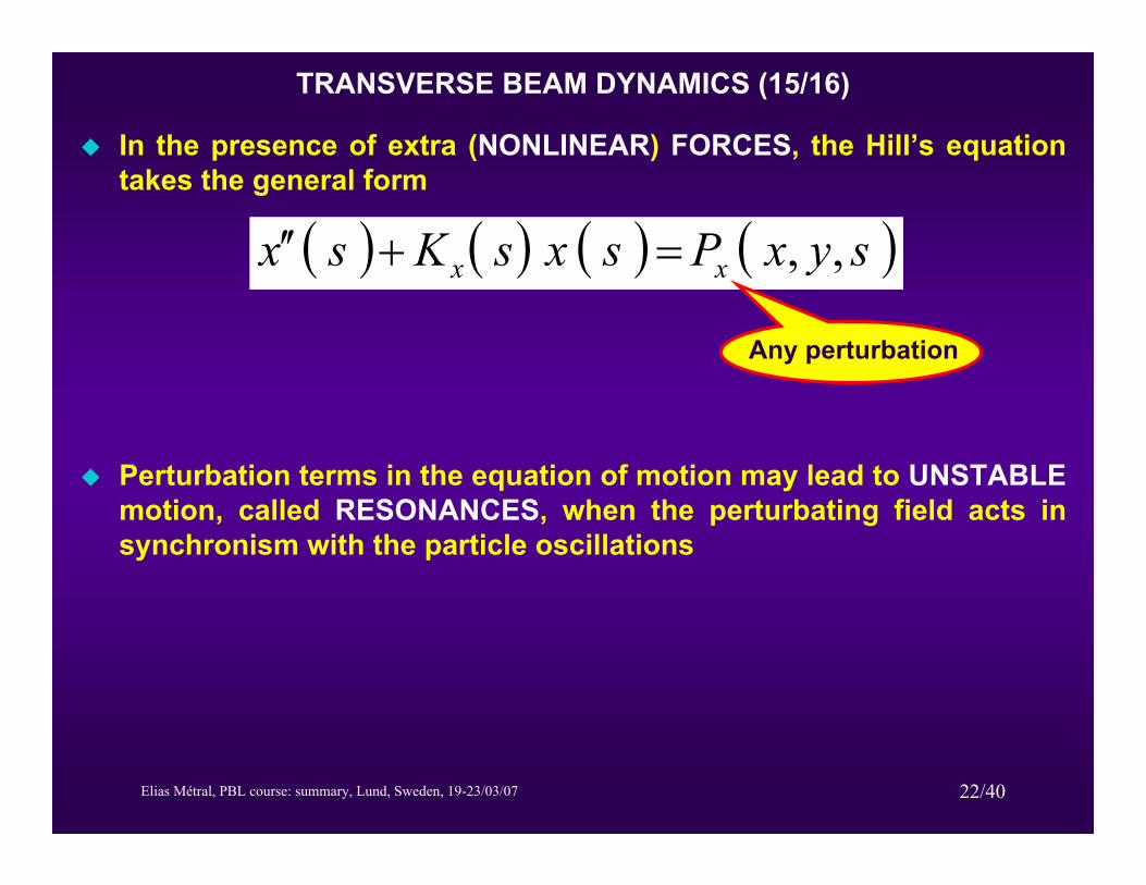
TRANSVERSE BEAM DYNAMICS (15/16)
In the presence of extra (NONLINEAR) FORCES, the Hill’s equation takes the general form
( ) ( ) ( ) ( )syxPsxsKsx xx ,,=+′′
Any perturbation
Perturbation terms in the equation of motion may lead to UNSTABLEmotion, called RESONANCES, when the perturbating field acts in synchronism with the particle oscillations
Elias Métral, PBL course: summary, Lund, Sweden, 19-23/03/07 23/40
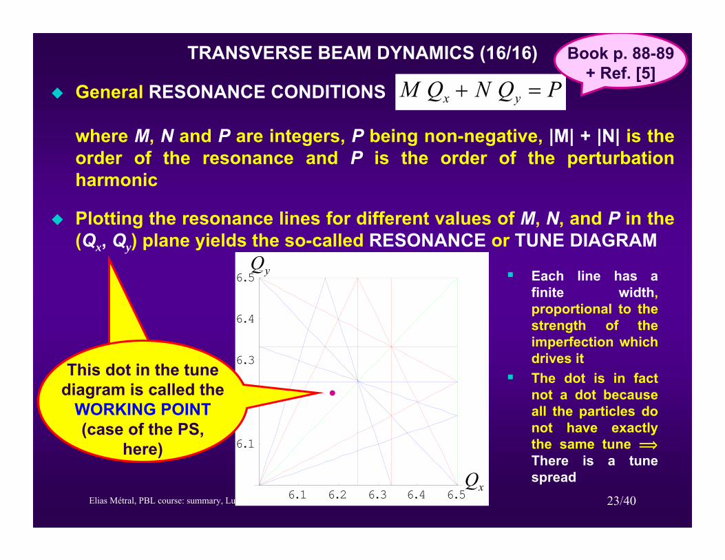
TRANSVERSE BEAM DYNAMICS (16/16)
General RESONANCE CONDITIONS PQNQM yx =+
where M, N and P are integers, P being non-negative, |M| + |N| is the order of the resonance and P is the order of the perturbation harmonic
Plotting the resonance lines for different values of M, N, and P in the (Qx, Qy) plane yields the so-called RESONANCE or TUNE DIAGRAM
Book p. 88-89 + Ref. [5]
6.1 6.2 6.3 6.4 6.5Qx
6.1
6.2
6.3
6.4
6.5Qy
xQ
yQ
This dot in the tune diagram is called the
WORKING POINT(case of the PS,
here)
Each line has a finite width, proportional to the strength of the imperfection which drives itThe dot is in fact not a dot because all the particles do not have exactly the same tune îThere is a tune spread
Elias Métral, PBL course: summary, Lund, Sweden, 19-23/03/07 24/40
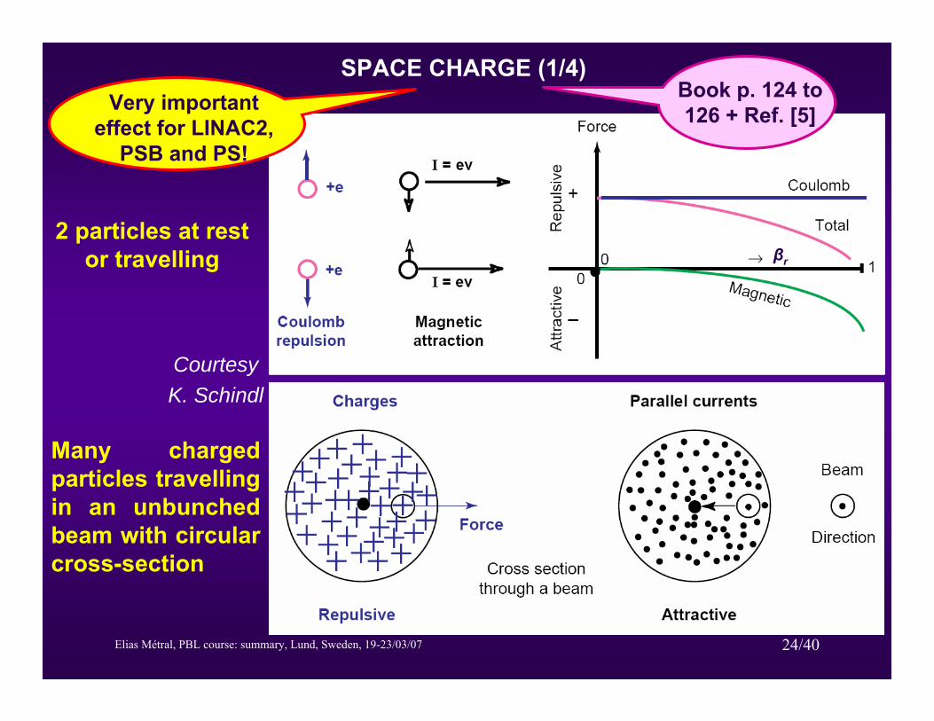
2 particles at rest or travelling
Many charged particles travellingin an unbunchedbeam with circular cross-section
Courtesy K. Schindl
βr
SPACE CHARGE (1/4)Very important
effect for LINAC2, PSB and PS!
Book p. 124 to 126 + Ref. [5]
Elias Métral, PBL course: summary, Lund, Sweden, 19-23/03/07 25/40
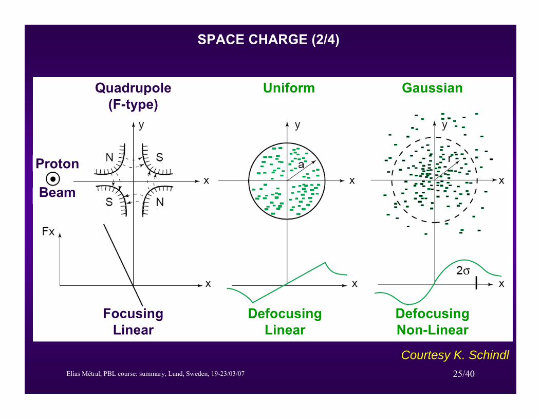
Quadrupole(F-type)
FocusingLinear
Uniform
DefocusingLinear
Gaussian
DefocusingNon-Linear
Proton
Beam
Courtesy K. Schindl
SPACE CHARGE (2/4)
Elias Métral, PBL course: summary, Lund, Sweden, 19-23/03/07 26/40
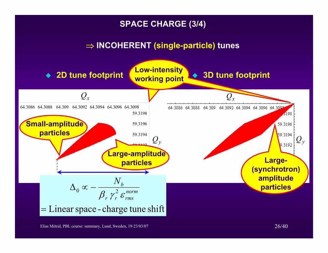
2D tune footprint 3D tune footprint
64.3086 64.3088 64.309 64.3092 64.3094 64.3096 64.3098
59.3186
59.3188
59.319
59.3192
59.3194
59.3196
59.319864.3086 64.3088 64.309 64.3092 64.3094 64.3096 64.3098
59.3186
59.3188
59.319
59.3192
59.3194
59.3196
59.3198
xQ
yQ
xQ
yQ
xQ
yQ
Low-intensity working point
Large-(synchrotron)
amplitudeparticles
SPACE CHARGE (3/4)
shift tunecharge-spaceLinear
Δ 20
=
−∝ normrmsrr
bNεγβ
Small-amplitudeparticles
Large-amplitudeparticles
⇒ INCOHERENT (single-particle) tunes
Elias Métral, PBL course: summary, Lund, Sweden, 19-23/03/07 27/40
5.9 6.1 6.2Qx
5.9
6.1
6.2
QyvQ
hQ
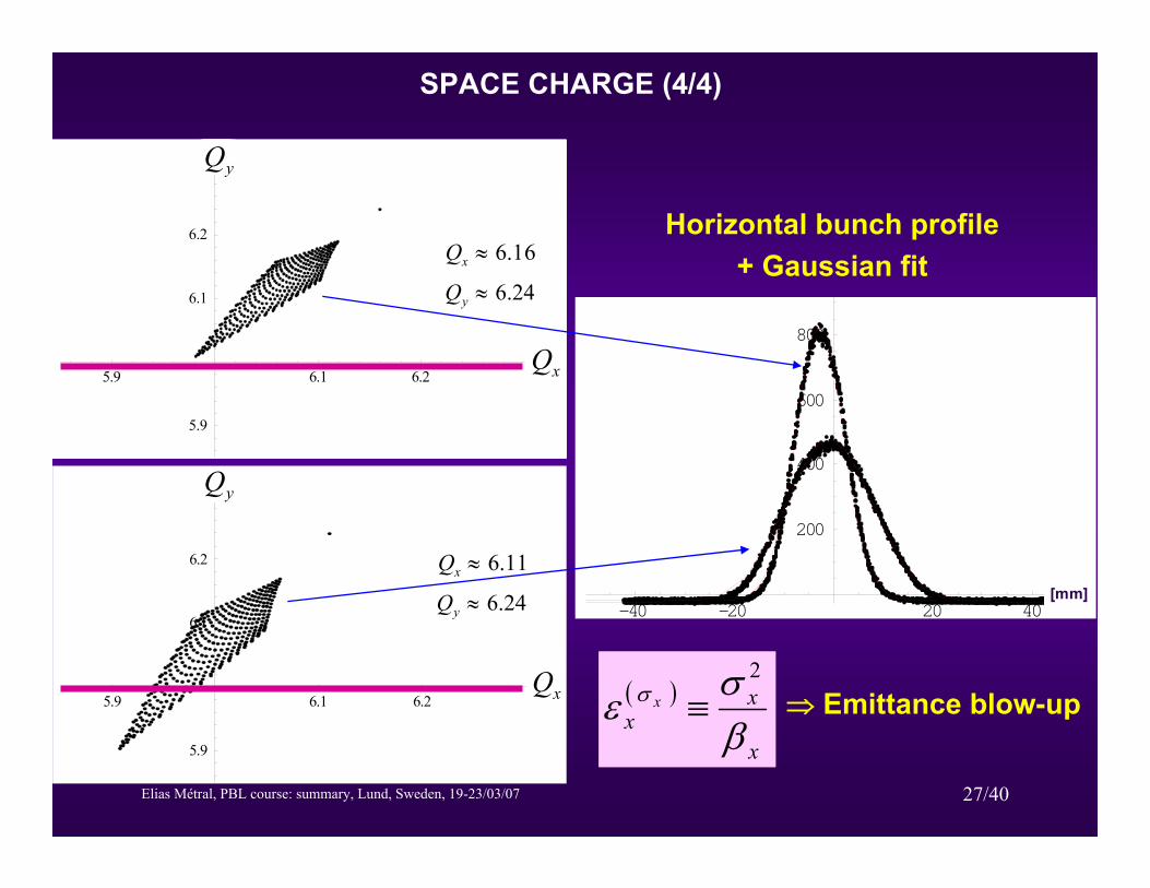
Case 3
11.6≈xQ
24.6≈yQ
-40 -20 20 40
200
400
600
800
[mm]
5.9 6.1 6.2Qx
5.9
6.1
6.2
Qy
Case 1
16.6≈xQ
24.6≈yQ
vQ
hQ
Horizontal bunch profile+ Gaussian fit
xQ
xQ
yQ
yQ
SPACE CHARGE (4/4)
( )
x
xx
x
βσε σ
2
≡ ⇒ Emittance blow-up

Elias Métral, PBL course: summary, Lund, Sweden, 19-23/03/07 28/40
LONGITUDINAL BEAM DYNAMICS (1/8)
The electric field is used to accelerate or decelerate the particles, and is produced by one or more RF (Radio-Frequency) CAVITIES
]m[s
]m[r
Courtesy L. Rinolfi
e-
Book p. 58 to 73 + Ref. [5]
Elias Métral, PBL course: summary, Lund, Sweden, 19-23/03/07 29/40
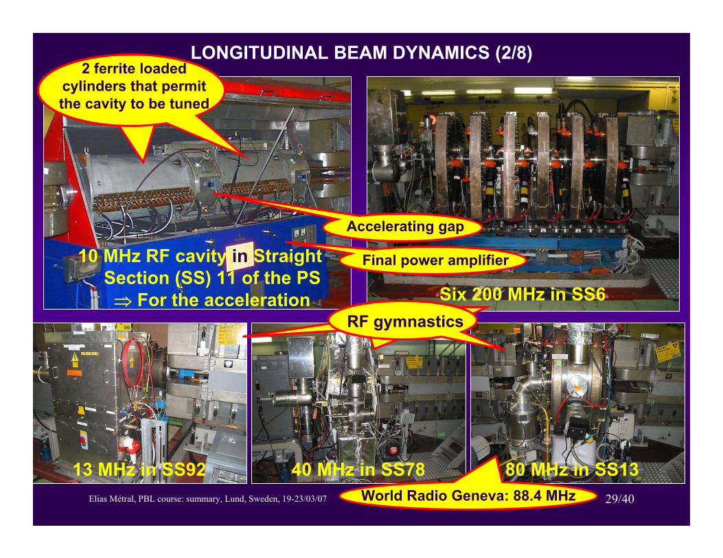
LONGITUDINAL BEAM DYNAMICS (2/8)
Six 200 MHz in SS6
13 MHz in SS92 40 MHz in SS78 80 MHz in SS13World Radio Geneva: 88.4 MHz
RF gymnastics
10 MHz RF cavity in Straight Section (SS) 11 of the PS ⇒ For the acceleration
Final power amplifier
2 ferrite loaded cylinders that permit the cavity to be tuned
Accelerating gap
Elias Métral, PBL course: summary, Lund, Sweden, 19-23/03/07 30/40
LONGITUDINAL BEAM DYNAMICS (3/8)
TRANSITION ENERGY: The increase of energy has 2 contradictory effects
An increase of the particle’s velocityAn increase of the length of the particle’s trajectory
According to the variations of these 2 parameters, the revolution frequency evolves differently
Below transition energy: The velocity increases faster than the length ⇒ The revolution frequency increasesAbove transition energy: It is the opposite case ⇒ The revolution frequency decreasesAt transition energy: The variation of the velocity is compensated by the variation of the trajectory ⇒ A variation of energy does not modify the frequency
Elias Métral, PBL course: summary, Lund, Sweden, 19-23/03/07 31/40
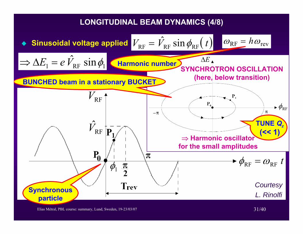
LONGITUDINAL BEAM DYNAMICS (4/8)
Sinusoidal voltage applied ( )tVV RFRFRF sinˆ φ= revRF ωω h=
RFV̂
RFV
tRFωφ =RFRFφ tRFRF ωφ =1φ
Synchronous particle
1RF1 sinˆ φVeE =Δ⇒
RFφ
EΔHarmonic numberSYNCHROTRON OSCILLATION
(here, below transition)
Courtesy L. Rinolfi
⇒ Harmonic oscillator for the small amplitudes
BUNCHED beam in a stationary BUCKET
TUNE Qz(<< 1)
Elias Métral, PBL course: summary, Lund, Sweden, 19-23/03/07 32/40
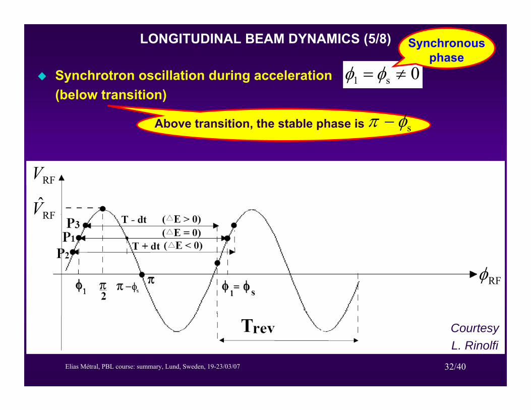
LONGITUDINAL BEAM DYNAMICS (5/8)
Synchrotron oscillation during acceleration(below transition)
0s1 ≠= φφ
Synchronous phase
RFV
RFV̂
RFφ
Above transition, the stable phase is sφπ −
Courtesy L. Rinolfi
Elias Métral, PBL course: summary, Lund, Sweden, 19-23/03/07 33/40
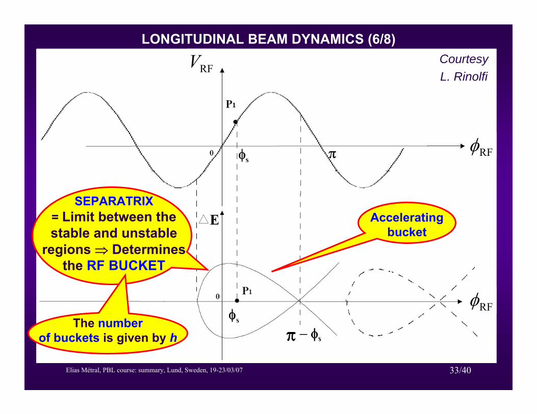
LONGITUDINAL BEAM DYNAMICS (6/8)
RFφ
RFφ
RFV
SEPARATRIX= Limit between the stable and unstable
regions ⇒ Determines the RF BUCKET
Courtesy L. Rinolfi
The number of buckets is given by h
Accelerating bucket
Elias Métral, PBL course: summary, Lund, Sweden, 19-23/03/07 34/40
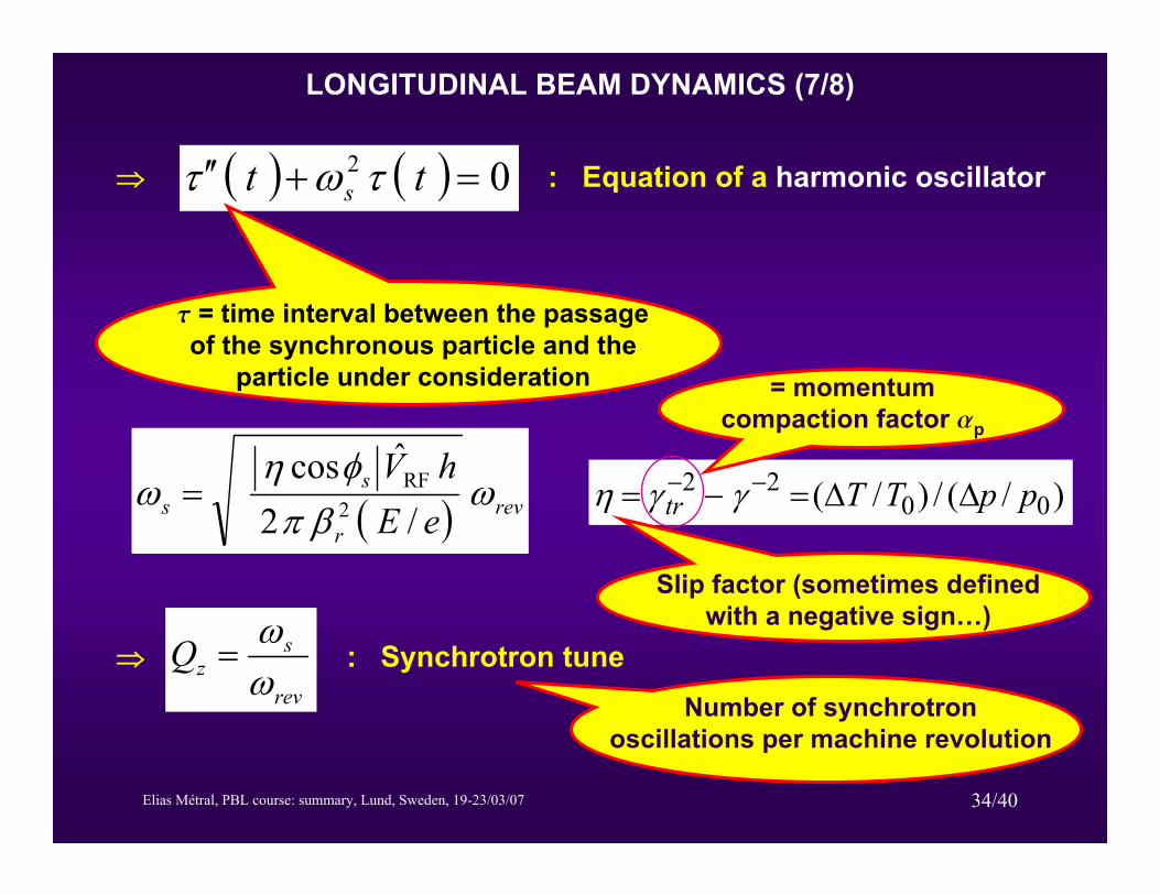
LONGITUDINAL BEAM DYNAMICS (7/8)
( ) revr
ss eE
hVω
βπφη
ω/2
ˆcos2
RF=
( ) ( ) 02 =+′′ tt s τωτ⇒ : Equation of a harmonic oscillator
t = time interval between the passage of the synchronous particle and the
particle under consideration
rev
szQ ω
ω=⇒ : Synchrotron tune
Number of synchrotron oscillations per machine revolution
)/(/)/( 0022 ppTTtr ΔΔ=−= −− γγη
Slip factor (sometimes defined with a negative sign…)
= momentum compaction factor ap
Elias Métral, PBL course: summary, Lund, Sweden, 19-23/03/07 35/40
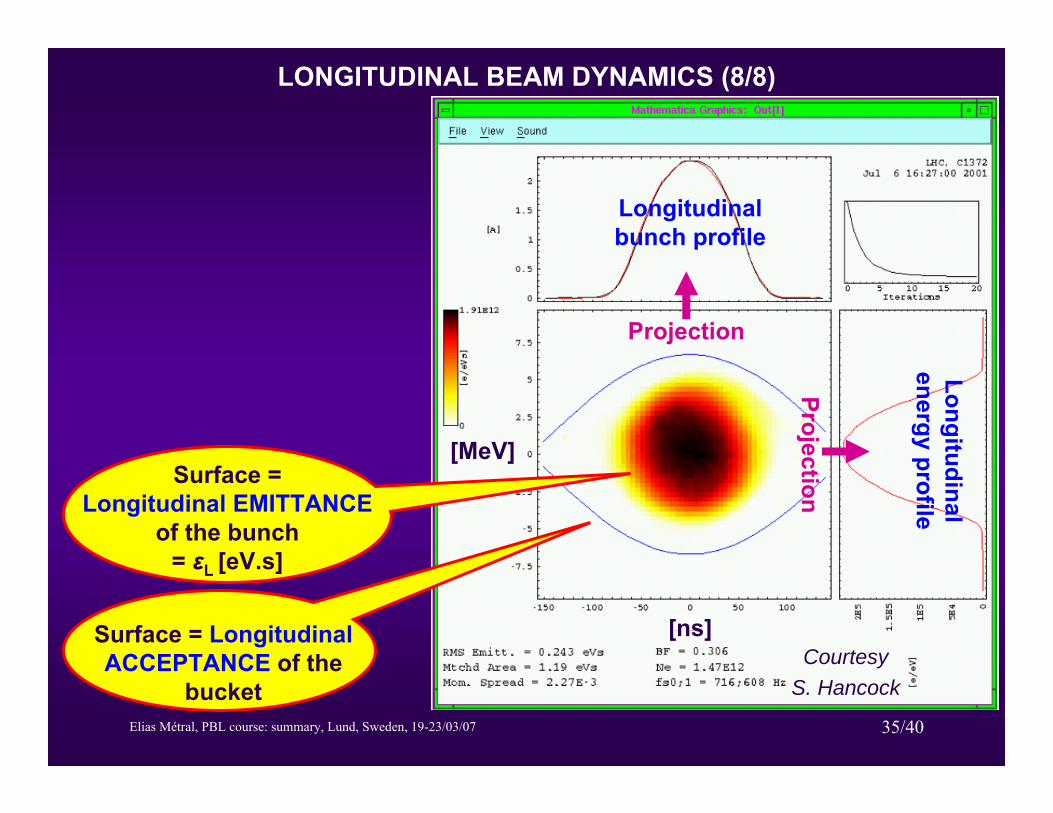
LONGITUDINAL BEAM DYNAMICS (8/8)
[MeV]
[ns]
Surface = Longitudinal EMITTANCE
of the bunch = εL [eV.s]
Surface = Longitudinal ACCEPTANCE of the
bucket
Projection
ProjectionLongitudinal bunch profile
Longitudinal energy profile
Courtesy S. Hancock
Elias Métral, PBL course: summary, Lund, Sweden, 19-23/03/07 36/40
SOLUTION OF THE TRANSVERSE PROBLEM (1/2)
Doubling the peak luminosity î Increasing the intensity (per bunch) by ÷2, i.e. by ~ 40%
î The space charge tune spread is increased by 40% (assuming the same transverse emittance)
Losses are observed and reduced by tuning the working point îThe space charge tune spread can be placed in a better position in the tune diagram where it overlaps less dangerous resonances…
The losses did not disappear completely î See next (real) picture. One has either to reduce the density Nb / en or compensate the resonances if one wants to suppress these losses
The transverse emittances still have to be checked î Because, as seen before, some resonances can lead to emittance blow-up…and emittance blow-up leads to less luminosity…
Elias Métral, PBL course: summary, Lund, Sweden, 19-23/03/07 37/40
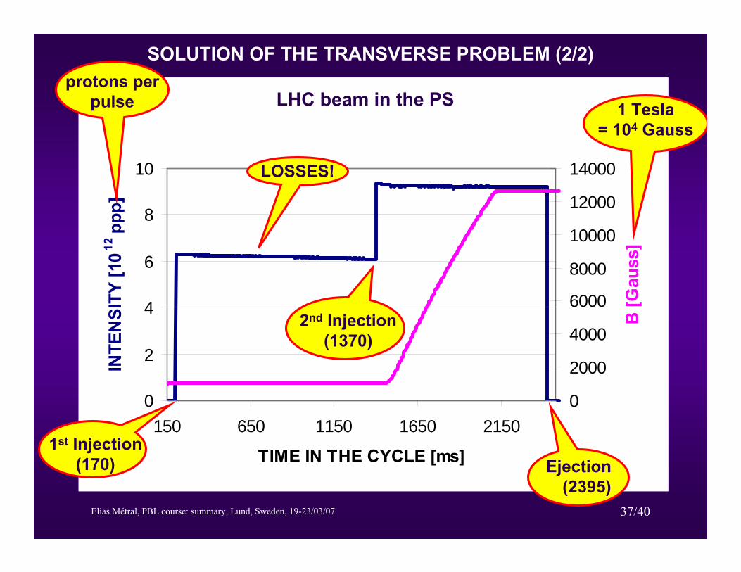
SOLUTION OF THE TRANSVERSE PROBLEM (2/2)
PS magnetic field for the LHC beam
0
2
4
6
8
10
150 650 1150 1650 2150
TIME IN THE CYCLE [ms]
INTE
NSI
TY [1
012 pp
p]
0
2000
4000
6000
8000
10000
12000
14000
B [G
auss
]
1st Injection(170) Ejection
(2395)
1 Tesla = 104 Gauss
2nd Injection(1370)
protons per pulse
LOSSES!
LHC beam in the PS
Elias Métral, PBL course: summary, Lund, Sweden, 19-23/03/07 38/40
SOLUTION OF THE LONGITUDINAL
PROBLEM
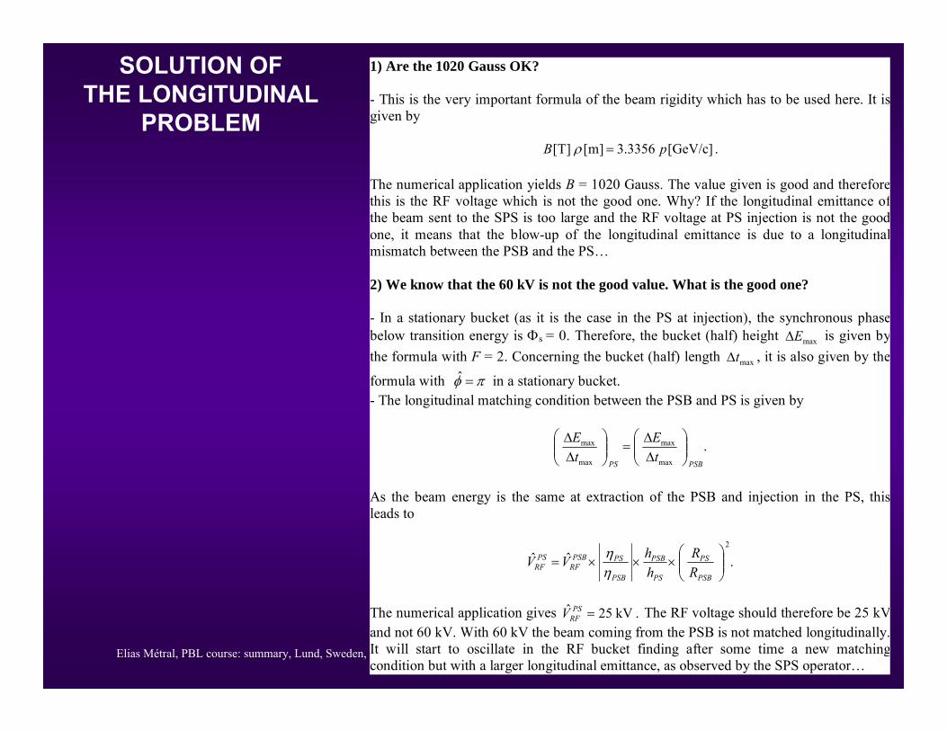
1) Are the 1020 Gauss OK? - This is the very important formula of the beam rigidity which has to be used here. It isgiven by .]GeV/c[3356.3]m[]T[ pB =ρ The numerical application yields B = 1020 Gauss. The value given is good and thereforethis is the RF voltage which is not the good one. Why? If the longitudinal emittance ofthe beam sent to the SPS is too large and the RF voltage at PS injection is not the goodone, it means that the blow-up of the longitudinal emittance is due to a longitudinalmismatch between the PSB and the PS… 2) We know that the 60 kV is not the good value. What is the good one? - In a stationary bucket (as it is the case in the PS at injection), the synchronous phasebelow transition energy is Φs = 0. Therefore, the bucket (half) height maxEΔ is given bythe formula with F = 2. Concerning the bucket (half) length maxtΔ , it is also given by the
formula with πφ =ˆ in a stationary bucket. - The longitudinal matching condition between the PSB and PS is given by
.max
max
max
max
PSBPStE
tE
⎟⎟⎠
⎞⎜⎜⎝
⎛ΔΔ
=⎟⎟⎠
⎞⎜⎜⎝
⎛ΔΔ
As the beam energy is the same at extraction of the PSB and injection in the PS, thisleads to
.ˆˆ2
⎟⎟⎠
⎞⎜⎜⎝
⎛×××=
PSB
PS
PS
PSB
PSB
PSPSBRF
PSRF R
RhhVV
ηη
The numerical application gives .kV25ˆ =PS
RFV The RF voltage should therefore be 25 kVand not 60 kV. With 60 kV the beam coming from the PSB is not matched longitudinally.It will start to oscillate in the RF bucket finding after some time a new matchingcondition but with a larger longitudinal emittance, as observed by the SPS operator…
Elias Métral, PBL course: summary, Lund, Sweden, 19-23/03/07 39/40
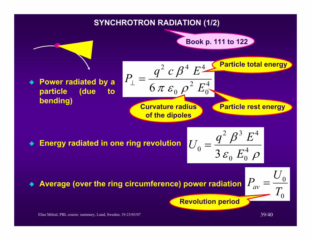
Power radiated by a particle (due to bending)
40
20
442
6 EEcqP
ρεπβ
=⊥
Particle rest energyCurvature radius of the dipoles
Particle total energy
Energy radiated in one ring revolution
Average (over the ring circumference) power radiation
ρεβ
400
432
0 3 EEqU =
0
0
TUPav =
Revolution period
SYNCHROTRON RADIATION (1/2)
Book p. 111 to 122

Elias Métral, PBL course: summary, Lund, Sweden, 19-23/03/07 40/40
7000104p0 [GeV/c]
6.7 keV3.3 GeVU0
2803.953096.175r [m]
LHCLEP
The RF system had therefore to compensate for an energy lost of ~3% of the total beam energy per turn!
The total average (over the ring circumference) power
radiation (per beam) is 3.9 kW(2808 bunches of 1.15 1011
protons)
SYNCHROTRON RADIATION (2/2)