pavement design manual
DESCRIPTION
Issued by Queensland Department of Main RoadsPavements & Materials BranchTRANSCRIPT

PAVEMENT DESIGN MANUAL Supplement to ‘Part 2: Pavement Structural Design’ of the Austroads Guide to Pavement Technology
Issued by Queensland Department of Main Roads Pavements & Materials Branch For document content enquiries: Principal Engineer (Pavement Design) Phone: (07) 3115 3079 Facsimile: (07) 3115 3055

IMPORTANT INFORMATION The requirements of this document represent Technical Policy of Main Roads and contain Technical Standards. Compliance with Main Roads Technical Standards is mandatory for all applications for the design, construction, maintenance and operation of road transport infrastructure in Queensland by or on behalf of the State of Queensland.
This document will be reviewed from time to time as the need arises and in response to improvement suggestions by users. Please send your comments and suggestions to the feedback email given below.
FEEDBACK Your feedback is welcomed. Please send to [email protected].
COPYRIGHT © State of Queensland (Department of Main Roads) 2009
Copyright protects this publication. Except for the purposes permitted by and subject to the conditions prescribed under the Copyright Act, reproduction by any means (including electronic, mechanical, photocopying, microcopying or otherwise) is prohibited without the prior written permission of the Queensland Department of Main Roads. Enquiries regarding such permission should be directed to the Road & Delivery Performance Division, Queensland Department of Main Roads.
DISCLAIMER This publication has been created for use in the design, construction, maintenance and operation of road transport infrastructure in Queensland by or on behalf of the State of Queensland.
The State of Queensland and the Department of Main Roads give no warranties as to the completeness, accuracy or adequacy of the publication or any parts of it and accepts no responsibility or liability upon any basis whatever for anything contained in or omitted from the publication or for the consequences of the use or misuse of the publication or any parts of it.
If the publication or any part of it forms part of a written contract between the State of Queensland and a contractor, this disclaimer applies subject to the express terms of that contract.
January 2009


Queensland Department of Main Roads Pavement Design Manual
January 2009 i
Table of Contents
1 INTRODUCTION...............................................................................................................................1 1.1 Foreword ..................................................................................................................................1 1.2 MR Pavement Design System .................................................................................................1 1.3 Scope and applicability ............................................................................................................2
1.3.1 General ......................................................................................................................2 1.3.2 Applying the MR Pavement Design System..............................................................2 1.3.3 MR Pavement Design System policy parameters .....................................................3
1.4 Definitions ................................................................................................................................4 2 PAVEMENT DESIGN........................................................................................................................8
2.1 Overview of MR Pavement Design System.............................................................................8 2.1.1 Design models and mechanical properties................................................................8 2.1.2 Designers...................................................................................................................8 2.1.3 Unbound granular design charts ...............................................................................8 2.1.4 Mechanistic design ....................................................................................................8 2.1.5 Estimate of life ...........................................................................................................8
2.2 Reliability..................................................................................................................................8 2.3 Selecting a trial pavement configuration and minimum standards ..........................................9
2.3.1 General ......................................................................................................................9 2.3.2 Project-specific factors.............................................................................................10 2.3.3 Specifications...........................................................................................................10 2.3.4 Minimum pavement standards ................................................................................10
2.4 Shoulders ...............................................................................................................................17 2.4.1 General ....................................................................................................................17 2.4.2 Shoulders with a lower structural standard..............................................................17 2.4.3 Unsealed shoulders .................................................................................................18
3 CONSTRUCTION AND MAINTENANCE CONSIDERATIONS......................................................20 3.1 General ..................................................................................................................................20 3.2 Unbound granular ..................................................................................................................20 3.3 Stabilised materials ................................................................................................................20 3.4 Temporary connections for HILI pavements..........................................................................21 3.5 Asphalt pavements.................................................................................................................21 3.6 Working platform....................................................................................................................21 3.7 Settlement ..............................................................................................................................22 3.8 Moisture ingress and maintenance ........................................................................................22 3.9 Trafficking of incomplete pavement .......................................................................................22 3.10 Thickness of bituminous seals ...............................................................................................22
4 ENVIRONMENT..............................................................................................................................23 4.1 General ..................................................................................................................................23 4.2 Climatic zones........................................................................................................................23 4.3 Water environment.................................................................................................................24 4.4 Minimising exposure to and influence of water......................................................................27
4.4.1 General ....................................................................................................................27 4.4.2 Design requirements................................................................................................27 4.4.3 During construction..................................................................................................28
4.5 Situations where pavement or subgrades cannot be protected ............................................28 4.6 Temperature environment......................................................................................................29
5 SUBGRADE ....................................................................................................................................30 5.1 General ..................................................................................................................................30

Pavement Design Manual Queensland Department of Main Roads
ii January 2009
5.2 Subgrade assessment........................................................................................................... 30 5.2.1 General ................................................................................................................... 30 5.2.2 Laboratory CBR test conditions .............................................................................. 31 5.2.3 Statistical analysis of CBR data .............................................................................. 31 5.2.4 Adoption of presumptive CBR values ..................................................................... 31 5.2.5 Variation in subgrade support with moisture changes............................................ 32
5.3 Subgrade water-induced volume change.............................................................................. 32 5.3.1 General ................................................................................................................... 32 5.3.2 Minimising volume change...................................................................................... 33 5.3.3 Cover over reactive subgrade................................................................................. 33
5.4 Select fill and treated material ............................................................................................... 34 5.5 Working platform ................................................................................................................... 34
5.5.1 In-service requirements .......................................................................................... 34 5.5.2 Contractor’s design requirements........................................................................... 35
5.6 Capping ................................................................................................................................. 35 5.7 Drainage layer ....................................................................................................................... 36 5.8 Combined subgrade treatments............................................................................................ 36 5.9 Elastic characterisation of subgrade materials...................................................................... 39
6 PAVEMENT MATERIALS .............................................................................................................. 40 6.1 Unbound granular.................................................................................................................. 40
6.1.1 General ................................................................................................................... 40 6.1.2 Determining modulus of unbound granular materials ............................................. 40
6.2 Modified granular materials ................................................................................................... 41 6.3 Stabilised granular material................................................................................................... 41
6.3.1 General ................................................................................................................... 41 6.3.2 Determining design modulus and Poisson’s ratio................................................... 42 6.3.3 Cracking .................................................................................................................. 42 6.3.4 Minimising cracks.................................................................................................... 43
6.4 Lean mix concrete ................................................................................................................. 43 6.5 Asphalt................................................................................................................................... 44
6.5.1 Asphalt types........................................................................................................... 44 6.5.2 Determining asphalt modulus and Poisson’s ratio.................................................. 44 6.5.3 Recycled asphalt..................................................................................................... 46 6.5.4 Minimising water infiltration..................................................................................... 46
6.6 Concrete ................................................................................................................................ 46 6.6.1 Base concrete ......................................................................................................... 46
7 DESIGN TRAFFIC.......................................................................................................................... 47 7.1 Average daily ESA in design lane in year of opening ........................................................... 47 7.2 Selecting design period and assessment period................................................................... 47 7.3 Identifying design lane........................................................................................................... 47 7.4 Initial daily heavy vehicles in the design lane........................................................................ 47 7.5 Growth rate and cumulative traffic volumes .......................................................................... 48 7.6 Project specific traffic load distribution .................................................................................. 48 7.7 Reduced design standard for sealed unbound granular pavements with average daily ESA < 100 in design lane in year of opening.................................................................................................... 48
8 DESIGN OF NEW FLEXIBLE PAVEMENTS ................................................................................. 50 8.1 General.................................................................................................................................. 50 8.2 Mechanistic procedure .......................................................................................................... 50
8.2.1 Selecting a trial pavement....................................................................................... 50 8.2.2 Consideration of post-cracking phase in cemented materials ................................ 50
8.3 Empirical design of unbound granular pavements with thin bituminous surfacing ............... 50 8.4 Modified granular pavements ................................................................................................ 51 8.5 Example design charts for mechanistic design ..................................................................... 51

Queensland Department of Main Roads Pavement Design Manual
January 2009 iii
9 DESIGN OF NEW RIGID PAVEMENTS.........................................................................................52 9.1 General ..................................................................................................................................52 9.2 Pavement types .....................................................................................................................52 9.3 Concrete channels .................................................................................................................52 9.4 Example design charts for rigid pavements...........................................................................53
10 COMPARISON OF DESIGNS ........................................................................................................54 10.1 General ..................................................................................................................................54
10.1.1 Assessment period ..................................................................................................54 10.1.2 Design inclusions.....................................................................................................55 10.1.3 Determining the optimal solution .............................................................................55 10.1.4 Selection constraints................................................................................................56
11 TYPICAL CROSS SECTIONS ........................................................................................................57 11.1 Typical cross sections ............................................................................................................57 11.2 Pavement structures ..............................................................................................................58 11.3 Pavement edge details...........................................................................................................60
12 REFERENCES................................................................................................................................61 APPENDIX 1 .............................................................................................................................................I APPENDIX 2 ............................................................................................................................................II


Queensland Department of Main Roads Pavement Design Manual
January 2009 1
1 INTRODUCTION
1.1 Foreword The Queensland Department of Main Roads (MR) Pavement Design Manual (this manual) is written as a supplement to ‘Part 2: Pavement Structural Design’ of the Austroads Guide to Pavement Technology (Austroads, 2008), hereafter referred to as Part 2 of the Austroads guide. The MR Pavement Design Manual, used in conjunction with Part 2 of the Austroads guide and the other components of the MR Pavement Design System, provides requirements for the design of new pavements for MR.
Designers are also referred to the following MR documents:
● Pavement Surfacings Manual
● Pavement Rehabilitation Manual
● Road Planning and Design Manual
1.2 MR Pavement Design System The MR Pavement Design System, which includes this manual, sets out MR specific pavement design requirements. For most fundamental design principles Part 2 of the Austroads guide is used. For Main Roads purposes, the MR components of the Pavement Design System take precedence over Part 2 of the Austroads guide, if and where they differ.
The MR Pavement Design System includes all the following documents, systems and design properties:
a) MR documents and systems
i) Pavement Design Manual
ii) standard specifications
iii) supplementary specifications
iv) technical standards
v) standard drawings
vi) standard test methods
vii) technical notes
viii) engineering policies
ix) engineering notes
x) quality requirements
b) ‘Part 2: Pavement Structural Design’ of the Austroads Guide to Pavement Technology
c) design properties
i) Material design properties must be those stipulated in the MR Pavement Design System described above. In particular, properties such as moduli, fatigue constants and Poisson’s ratios must be those stipulated in this manual, or if not stated, those given in Part 2 of the Austroads guide.
ii) The design properties used in the MR Pavement Design System are based on the products, components and materials of the pavement conforming to the requirements of the documents listed in 1.2 a) above.

Pavement Design Manual Queensland Department of Main Roads
2 January 2009
1.3 Scope and applicability 1.3.1 General The MR Pavement Design Manual is intended as a guide for professional, trained, experienced and knowledgeable pavement designers who are required to:
a) work within the confines of Main Roads organisational policies, guidelines and road network requirements
b) be aware of, assess and apply risk management and budgetary constraints to the road system as a whole and its various components
c) take into account local area or project specific issues
d) optimise initial designs and in-service treatments to suit budget and whole-of-life cost issues.
1.3.2 Applying the MR Pavement Design System The MR Pavement Design System must:
a) be applied as a complete and integrated system. No part can be used in isolation from the others, nor shall other models, methodologies, specifications, properties and/or materials be substituted for those required by the MR Pavement Design System.
b) not be used on its own to form part of any contract including, but not limited to, those for the following delivery mechanisms
i) design
ii) design and construct
iii) design-construct-maintain
iv) alliance
v) partnering
vi) build-own-operate-transfer
In such cases, a separate, comprehensive and robust set of project-specific requirements must be developed.
c) not be used for ‘performance’ based contracts and/or with ‘performance’ based specifications. ‘Performance’ contracts and standards must be based on functional requirements guaranteed for the service life of the project.
d) not be used in isolation where functional requirements are specified. Where used by Main Roads as part of an infrastructure delivery model that includes functional requirements, achievement of the functional requirements must be based on requirements for initial construction and interventions that involve periodic treatments including overlays, reseals, rejuvenation, re-texturing and so on.
e) not be used for any purpose other than within the context described above. In particular, it must not be used for
i) designing facilities other than those to be designed directly for Main Roads. It must not be used for facilities including, but not limited to container and freight yards, mining roads and airports.
ii) designing facilities for any Legal Entity other than the State of Queensland
iii) designing projects with parameters other than those set out in Section 1.2 for the Queensland road network
iv) unsealed pavements; segmental block or flag pavements; roller compacted concrete pavements; or any pavement not covered by an MR standard.

Queensland Department of Main Roads Pavement Design Manual
January 2009 3
Because of differences between design inputs and whole-of-life realities (e.g. traffic growth, enforcement of and legislative changes to legal axle loads and tyre pressures, variability in construction control and ongoing maintenance and rehabilitation) the analytical processes and tools contained herein can provide only an indication of future pavement performance.
If a contract interface involves a planning and/or design component, requirements separate to the MR Pavement Design System must be developed to address the means of supplying an acceptable design process and design to the owner/client/principal.
1.3.3 MR Pavement Design System policy parameters The MR Pavement Design System has evolved and been developed to provide solutions that best serve the needs of the MR controlled road network as a whole and applies only in this context. The policy parameters that provided guidance and the context of developments to date have included:
a) a historic priority for
i) all-weather connections with the consequence of lower initial standards in order to favour maximum length constructed
ii) an adequate level of service over the whole network within the context of budgetary constraints and the comparatively large geographical area with relatively low population density
b) a project delivery system requiring a defined contract between the owner and the contractor, for construction only, based on detailed drawings, specifications and test methods.
Imperatives that have had to be considered in recent times include:
a) high cost of maintenance interventions and associated user disruptions on highly trafficked urban roads, leading to the lowest whole-of-life cost solution for such pavements being high load intensity low intervention (HILI) pavements
b) increasing load intensities caused by increases in vertical loading and major increases in horizontal shear loading caused by increased truck gross masses. This has required stiffer and stronger pavement bases and surface layers.
c) increased expectations about safety requirements, leading to increases in surface property requirements such as macrotexture and microtexture but also requiring stiffer and stronger pavement base layers to support these requirements
d) a greater emphasis on whole-of-life cost rather than initial cost.

Pavement Design Manual Queensland Department of Main Roads
4 January 2009
1.4 Definitions Table 1.4-1 – Definitions
Term Description
assessment period The time span over which total costs for the pavement are determined so that whole-of-life cost comparisons can be made between alternative pavement design options. Refer to Table 7.2-1 for determination of the assessment period. The assessment period may be the same as the design period, or there may be several design periods within the assessment period due to decisions to reconstruct or rehabilitate the pavement at intermediate intervals.
Part 2 of the Austroads guide
‘Part 2: Pavement Structural Design’ Guide to Pavement Technology (Austroads 2008)
base layer The main structural layer nearest to the surface in a pavement.
binder layer An asphalt layer that is placed between an asphalt base layer and an asphalt surface layer. The binder layer is included for its better workability to reduce permeability and improve roughness levels.
capping layer A layer that provides cover over an in situ material that has a design CBR of less than 3.0% but not less than 1.0%.
CBR California bearing ratio
cover over reactive subgrade
A thickness of material beneath the lowest pavement layer intended to reduce water-induced volume change effects on the pavement where there are in situ materials with the potential for water-induced volume change. Cover thickness may include any working platform, select fill, capping layer and/or drainage layer.
curling Differential movement, usually vertical, in a concrete pavement caused by temperature differences through the cross-section of the pavement.
constituents Materials and/or components within a product.
deep strength asphalt pavement
A pavement structure consisting of a minimum total thickness of 175 mm of dense graded asphalt over a cementitiously stabilised subbase (subbase thickness range 150–200 mm).
design period Main Roads definition (this applies to Main Roads works) The time span considered appropriate for the major structural elements of the road pavement to function without rehabilitation and/or reconstruction. Treatments, such as replacement of surfacing layers and stage construction treatments, that maintain the integrity of the other components of the pavement are included within the design period. Austroads definition The time span considered appropriate for the road pavement to function without major rehabilitation and/or reconstruction.
drainage layer A layer located between the pavement and the untreated subgrade that intercepts water and/or breaks capillary rise.

Queensland Department of Main Roads Pavement Design Manual
January 2009 5
Term Description
flexible composite pavement
A pavement structure consisting of a minimum total thickness of 175 mm of dense graded asphalt over a lean mix concrete subbase (subbase thickness range 170–240 mm).
flexible pavement Unbound granular, modified granular or asphalt pavements.
full depth asphalt pavement
A pavement structure consisting of full depth asphalt usually over a working platform.
functional characteristics
Characteristics provided by the particular pavement that address the necessities for traffic and are expressed in terms of lane availability, rideability, grade, cross-fall, water film thickness, flood immunity, skid resistance, etc.
functional requirements
Requirements related to a standard of service for the pavement user, such as roughness, grade, cross-fall, rutting, surface defects, texture depth, skid resistance, delineation, visibility, etc.
HILI pavement High load intensity, low intervention pavement as defined in Table 2.3-2.
load intensity Traffic loading applied to the pavement over a specified time period, comprising the accumulation of applications of a variety of pavement contact stresses and repetitions derived from the traffic spectrum, vehicle frequency and growth rate.
lower subbase The layer beneath the subbase layer
low pavement water content environment
A low pavement water content environment is where the pavement: a) has an adequate and well maintained seal; b) is not subject to flooding; c) has adequate surface and subsurface drains; d) has no standing and / or ponded water within 5 m laterally of the trafficked lane(s); e) has no water within 2 m vertically from the bottom of the lowest pavement layer unless there is a minimum 150 mm thick capillary break layer; and f) is located where the average rainfall is less than 500 mm / year and the Thornthwaite Index is less than 0.
Main Roads (MR) The State of Queensland operating through the Queensland Department of Main Roads
mechanical properties
Properties that can be used as direct inputs into a mathematical equation and/or model, such as layered linear elastic theory or finite element. At this time only the layered linear elastic model CIRCLY is calibrated for use.
MR Pavement Design System
Main Roads Pavement Design System as defined in Section 1.2 and applied as described in Section 1.3.
MR Pavement Design Manual
This manual.
MR Specifications and Standards
Main Roads standard specifications, technical standards and supplementary specifications current at the time of use.
pavement rehabilitation
The restoration of an unplanned distressed/failed pavement or the extension of the life of a pavement that has exceeded its design life, so that it may be expected to function at a satisfactory level of service for a further Design Period.
Pavement Design Manual Queensland Department of Main Roads
6 January 2009
Term Description
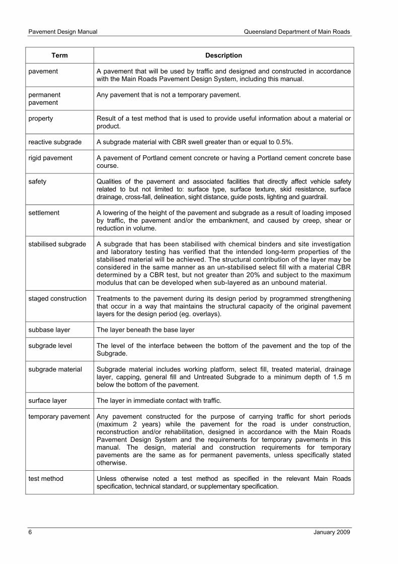
pavement A pavement that will be used by traffic and designed and constructed in accordance with the Main Roads Pavement Design System, including this manual.
permanent pavement
Any pavement that is not a temporary pavement.
property Result of a test method that is used to provide useful information about a material or product.
reactive subgrade A subgrade material with CBR swell greater than or equal to 0.5%.
rigid pavement A pavement of Portland cement concrete or having a Portland cement concrete base course.
safety Qualities of the pavement and associated facilities that directly affect vehicle safety related to but not limited to: surface type, surface texture, skid resistance, surface drainage, cross-fall, delineation, sight distance, guide posts, lighting and guardrail.
settlement A lowering of the height of the pavement and subgrade as a result of loading imposed by traffic, the pavement and/or the embankment, and caused by creep, shear or reduction in volume.
stabilised subgrade A subgrade that has been stabilised with chemical binders and site investigation and laboratory testing has verified that the intended long-term properties of the stabilised material will be achieved. The structural contribution of the layer may be considered in the same manner as an un-stabilised select fill with a material CBR determined by a CBR test, but not greater than 20% and subject to the maximum modulus that can be developed when sub-layered as an unbound material.
staged construction Treatments to the pavement during its design period by programmed strengthening that occur in a way that maintains the structural capacity of the original pavement layers for the design period (eg. overlays).
subbase layer The layer beneath the base layer
subgrade level The level of the interface between the bottom of the pavement and the top of the Subgrade.
subgrade material Subgrade material includes working platform, select fill, treated material, drainage layer, capping, general fill and Untreated Subgrade to a minimum depth of 1.5 m below the bottom of the pavement.
surface layer The layer in immediate contact with traffic.
temporary pavement Any pavement constructed for the purpose of carrying traffic for short periods (maximum 2 years) while the pavement for the road is under construction, reconstruction and/or rehabilitation, designed in accordance with the Main Roads Pavement Design System and the requirements for temporary pavements in this manual. The design, material and construction requirements for temporary pavements are the same as for permanent pavements, unless specifically stated otherwise.
test method Unless otherwise noted a test method as specified in the relevant Main Roads specification, technical standard, or supplementary specification.

Queensland Department of Main Roads Pavement Design Manual
January 2009 7
Term Description
treated material Material treated with lime and/or cement in accordance with the relevant Main Roads specification, technical standard, or supplementary specification.
UCS Unconfined compressive strength.
unbound granular pavement material
A material complying with the relevant Main Roads specification, technical standard, or supplementary specification that consists of graded aggregates and may include clay.
unbound granular - acceptable environment
An unbound granular – acceptable environment generally includes, in addition to the specification requirements: a) Full width seal (an alternative for low traffic volumes is a low permeability select fill unsealed shoulder where whole-of–life costing confirms it is economical for the particular situation); b) Adequately designed, constructed and maintained surface and subsurface drainage; c) Open table drains in cuttings; d) No standing and / or ponded water within 5 m laterally of the trafficked lane(s); e) No water within 2 m vertically unless there is a full width drainage / capillary break layer; f) Degree of saturation limits achieved and maintained for all layers; h) All layers are tested with a 4 day soaked CBR (except that an unsoaked CBR can be used for subbase in low pavement water content environements); i) Pavement is not subject to water inundation or flooding that lasts for more than 1 day (protection such as fully enclosed low permeability verges, drainage / capillary break layer, full width seal and pavement drains may be required).
untreated subgrade Natural unprocessed material, other than that moved from another location and/or compacted at the location, where the characteristics of the subgrade are to be determined to assess: a) the need for one or more of the following elements: capping layer; cover over
reactive subgrade; drainage layer and/or combined capping/drainage layer b) subgrade design CBR and swell.
warping Differential movement, usually vertical, in a concrete pavement caused by water content differences through the cross-section of the pavement.
water-induced volume change
Change in the volume of the subgrade material resulting from a change in water content usually on a reactive subgrade material.
weighted plasticity index (WPI)
The product of the plasticity index and percentage passing the AS 0.425 mm sieve
working platform A layer that is part of the subgrade and which provides: • access for construction traffic • a platform on which to construct the pavement layers • protection to the underlying materials.

Pavement Design Manual Queensland Department of Main Roads
8 January 2009
2 PAVEMENT DESIGN
2.1 Overview of MR Pavement Design System 2.1.1 Design models and mechanical properties Pavement design comprises empirical and mechanistic components.
The MR Pavement Design System utilises mathematical models to provide a logical framework within which to apply existing knowledge to the structural design of pavements. The models utilise mechanical properties such as modulus and Poisson’s Ratio. However, the direct measurement of these mechanical properties and the mechanistic model are not as robust as in other disciplines. Direct measurements must:
a) be statistically analysed to account for the considerable variation in pavement materials
b) have a 95% confidence level applied, unless stated otherwise
c) be considered as information additional to and integrated with values interpolated and/or extrapolated from the total calibration of the model
d) be used only in the context of the overall design system.
Where provided, the values given in the MR Pavement Design Manual must be used.
2.1.2 Designers Adequate design is possible only when carried out by professional, trained, experienced, and knowledgeable personnel. It requires consideration and integration of all inputs including local conditions, material characteristics, cross-sections, loading, design models, road user safety and constructability.
2.1.3 Unbound granular design charts The unbound granular design chart considers only rutting and shape loss.
2.1.4 Mechanistic design Mechanistic pavement design, utilising layered linear elastic theory, considers only three distress types: rutting and shape loss, fatigue of asphalt, and fatigue of cement stabilised materials.
For concrete pavements designed utilising this Manual, the design method for base thickness considers two distress types: fatigue of the base and erosion of the subbase/subgrade.
Other types of distress, such as those caused by horizontal stresses on grades, at intersections and on curves, or by environmental influences such as temperature and water, are not directly assessed by these design methods. These forms of distress have to be constrained by other means such as specification of appropriate materials or provision of relevant cross-sections, pavement types and drainage. Consequently, this Manual cannot be used in isolation and must be used in conjunction with all other components of the MR Pavement Design System.
2.1.5 Estimate of life The MR Pavement Design System will provide an estimate of the life of various pavement elements. To maintain the functionality of the pavement, including for the initial design period, interventions are required to replace, overlay and/or rejuvenate elements of the pavement. Regular pavement monitoring, with input from designs in accordance with this Manual, is essential to determine when these interventions are to occur.
2.2 Reliability The Austroads reliability guidelines (Part 2 of the Austroads guide, Section 2.2.1.2) consider only the following structural distress modes:

Queensland Department of Main Roads Pavement Design Manual
January 2009 9
a) for pavements designed with layered linear elastic theory
i) fatigue of asphalt
ii) fatigue of cemented materials
iii) rutting and shape loss of unbound granular materials and subgrade
b) for concrete pavements designed with Westergaard and finite element theory
i) fatigue of concrete base
ii) erosion of subbase/subgrade.
These reliability guidelines were based on general assessments of network performance. As the underlying causes of performance vary widely over the network, these probabilities can not be used for determining the reliability of a specific project or in the contract interface for a specific project.
The reliability guidelines are not appropriate for assessing reliability for other distress modes including, but not limited to, stripping or rutting of asphalt, roughness, skid resistance, and distress caused by environmental factors.
The choice of reliability is influenced by the classification/function of the road, its location and intended usage both prior to and after the completion of the design period. It is to be defined in accordance with Main Roads policy. Judgement of the appropriateness of the reliability level has to be based on the overall network performance of similar designs under similar conditions.
The minimum reliability levels to be used in the design of MR projects are given in Table 2.2-1. These reliability levels are to be used for the design of both temporary and permanent pavements.
Table 2.2-1 – Minimum reliability levels
Road category Reliability (%)
All roads, or sections of road, where intervention costs are very high or traffic management is very difficult1
97.5
Motorways, highways and main roads with lane AADT > 2000 97.5
Highways and main roads with lane AADT > 500 and ≤ 2000 95
Minor roads with lane AADT ≤ 500 90 Note: 1) Examples include high traffic volume metropolitan highways and arterials roads, mountainous sections, flood-ways,
intersections and approaches to structures such as bridges.
2.3 Selecting a trial pavement configuration and minimum standards 2.3.1 General Appropriate pavement configurations vary markedly with the function of the road, traffic loading, availability of materials and environment.
Pavement types and standards given in Table 2.3-1 to Table 2.3-5 are based on straight alignments with flat grades. The minimum layer thicknesses given are absolute minimums and the actual adopted layer thicknesses must be designed for fatigue and deformation requirements. Temporary pavement types are for temporary use while the permanent pavement is constructed, maintained, overlaid or re-constructed.
Where a permanent pavement is temporarily trafficked during construction, the damage resulting from the temporary trafficking must be included in the design calculations for the permanent pavement.

Pavement Design Manual Queensland Department of Main Roads
10 January 2009
2.3.2 Project-specific factors There are a number of project-specific factors that could not be taken into account in the development of the pavement type selection tables. Consequently, there will be occasions when the pavement type and/or pavement details will need to be changed from those given in the tables. Project-specific factors that may influence pavement selection include, but are not limited to:
a) horizontal shear stresses on grades, curves and intersections
b) pavement contact stresses higher than those used in the development of the current pavement design models and specifications
c) availability of materials
d) availability and adequacy of construction equipment, materials and expertise
e) construction constraints (e.g. construction under traffic)
f) changes to the function/classification of the road during the design period
g) changes to the road network during the design period
h) specific functional requirements (e.g. safety, noise)
i) current and future traffic characteristics
j) settlement and/or water-induced volume change. Where settlement and/or water-induced volume change is likely and cannot be reduced to an acceptable level, stiff pavements, such as concrete, stabilised or modified, must not be used.
k) whole-of-life costs. Whole-of-life costs must include direct and indirect costs of interventions such as raising drainage structures, increasing clearances, raising safety barriers, providing temporary access, maintaining alternative routes, delays and disruptions to road users, etc.
l) current and future budget considerations.
m) local environmental conditions, including
i) unbound granular pavements
ii) concrete pavements
Concrete pavements must have their complete cross-section (thickness and width) completed within a month to minimise differential and potentially detrimental movement.
iii) asphalt pavements
Asphalt pavements must be kept as dry as possible as water is a contributor to stripping.
2.3.3 Specifications Main Roads specifications or technical standards shall be used.
2.3.4 Minimum pavement standards Minimum pavement standards are given in Table 2.3-1 to Table 2.3-5, with primary selection based on traffic loading in terms of the average daily ESA in the design lane in the year of opening.
When selecting a pavement standard from these tables for a particular traffic level, a standard for a higher traffic category may be used. A standard for a lower traffic category may not be used.
There may be other factors that affect the choice of the pavement structure. Examples include those described below:
1) asphalt over granular pavements

Queensland Department of Main Roads Pavement Design Manual
January 2009 11
For asphalt over granular pavements, the lowest whole-of-life cost usually occurs when the asphalt thickness is sufficient to enable the asphalt to achieve a fatigue life at least the same as a reasonable pavement design life and the subgrade rutting life provided by the cover over subgrade.
While relatively thin1 asphalt surfaced granular pavements usually do not provide the lowest long-term whole-of-life solution, other factors may have a significant effect on selection of the pavement type, such as
a) budget constraints for initial construction
b) the cost-effectiveness of constructing relatively short sections
c) the high cost of appropriate granular base materials
d) noise.
In addition, in areas with surfaces subject to significant horizontal shear (such as grades, curves and intersections), the minimum thickness and type of asphalt should be determined so that it also accommodates this horizontal shear. In such cases the minimum thickness should be 100 mm. Thicker and/or polymer modified asphalt should be used for more severe applications. Models for determining the required thicknesses to resist shear forces are not currently available and local performance history is to be applied.
2) modified granular pavements
Modified granular pavements are not listed in Table 2.3-1 to Table 2.3-5. Where their performance has been established locally, they are to be specified and constructed in accordance with local District requirements, but within the following requirements:
a) The pavement must comprise a full depth modified material.
b) The design modulus for the base must be determined from repeat load triaxial testing and in situ deflection analysis of a similar existing pavement. When in situ analysis is not available, the maximum design modulus for the base shall be 350 MPa. The absolute maximum design modulus of the base shall be 600 MPa.
c) In all cases there must be a working platform and, where there is a reactive subgrade, cover over reactive subgrade.
d) The pavement must have at least a two-coat bitumen seal.
e) The potential for and risk associated with cracking must be recognized and accepted and appropriate interventions allowed for in the whole-of-life costing and maintenance during service;
f) Modified granular pavements cannot be used where the average daily ESA in the design lane in the year of opening is > 1000 or only a HILI pavement type is given in Table 2.3-1.
Typical pavement cross-sections for various pavement categories are given in Chapter 11.
1 Relatively thin asphalt surfaced granular pavements are those where the fatigue life of the asphalt cannot achieve a reasonable design life for the pavement. In these cases, the asphalt has to be regularly replaced, rejuvenated and/or overlaid.
Pavement Design Manual Queensland Department of Main Roads
12 January 2009
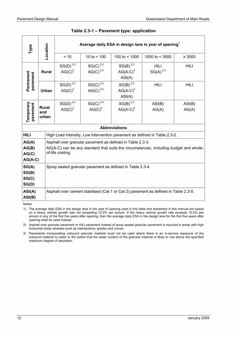
Table 2.3-1 – Pavement type: application
Average daily ESA in design lane in year of opening1
Type
Loca
tion
< 10 10 to < 100 100 to < 1000 1000 to < 3000 ≥ 3000
Rural SG(D) 2,3 AG(C)3
SG(C) 2,3 AG(C) 2,3
SG(B) 2,3 AG(A-C)3
ASt(A)
HILI SG(A) 2,3
HILI
Perm
anen
t pa
vem
ent
Urban SG(D) 2,3 AG(C)3
SG(C) 2,3 AG(C) 2,3
SG(B) 2,3 AG(A-C)3
ASt(A)
HILI HILI
Tem
pora
ry
pave
men
t
Rural and urban
SG(D) 2,3 AG(C)3
SG(C) 2,3 AG(C)3
SG(B) 2,3 AG(A-C)3
ASt(B) AG(A)
ASt(B) AG(A)
Abbreviations
HILI High Load Intensity, Low Intervention pavement as defined in Table 2.3-2.
AG(A) AG(B) AG(C) AG(A-C)
Asphalt over granular pavement as defined in Table 2.3-3. AG(A-C) can be any standard that suits the circumstances, including budget and whole-of-life costing.
SG(A) SG(B) SG(C) SG(D)
Spray sealed granular pavement as defined in Table 2.3-4.
ASt(A) ASt(B)
Asphalt over cement stabilised (Cat 1 or Cat 2) pavement as defined in Table 2.3-5.
Notes: 1) The average daily ESA in the design lane in the year of opening used in this table and elsewhere in this manual are based
on a heavy vehicle growth rate not exceeding 10.0% per annum. If the heavy vehicle growth rate exceeds 10.0% per annum in any of the first five years after opening, then the average daily ESA in the design lane for the first five years after opening shall be used instead.
2) Asphalt over granular pavement or HILI pavement instead of spray sealed granular pavement is required in areas with high horizontal shear stresses such as intersections, grades and curves.
3) Pavements incorporating unbound granular material must not be used where there is an in-service exposure of the unbound material to water to the extent that the water content of the granular material is likely to rise above the specified maximum degree of saturation.
Queensland Department of Main Roads Pavement Design Manual
January 2009 13
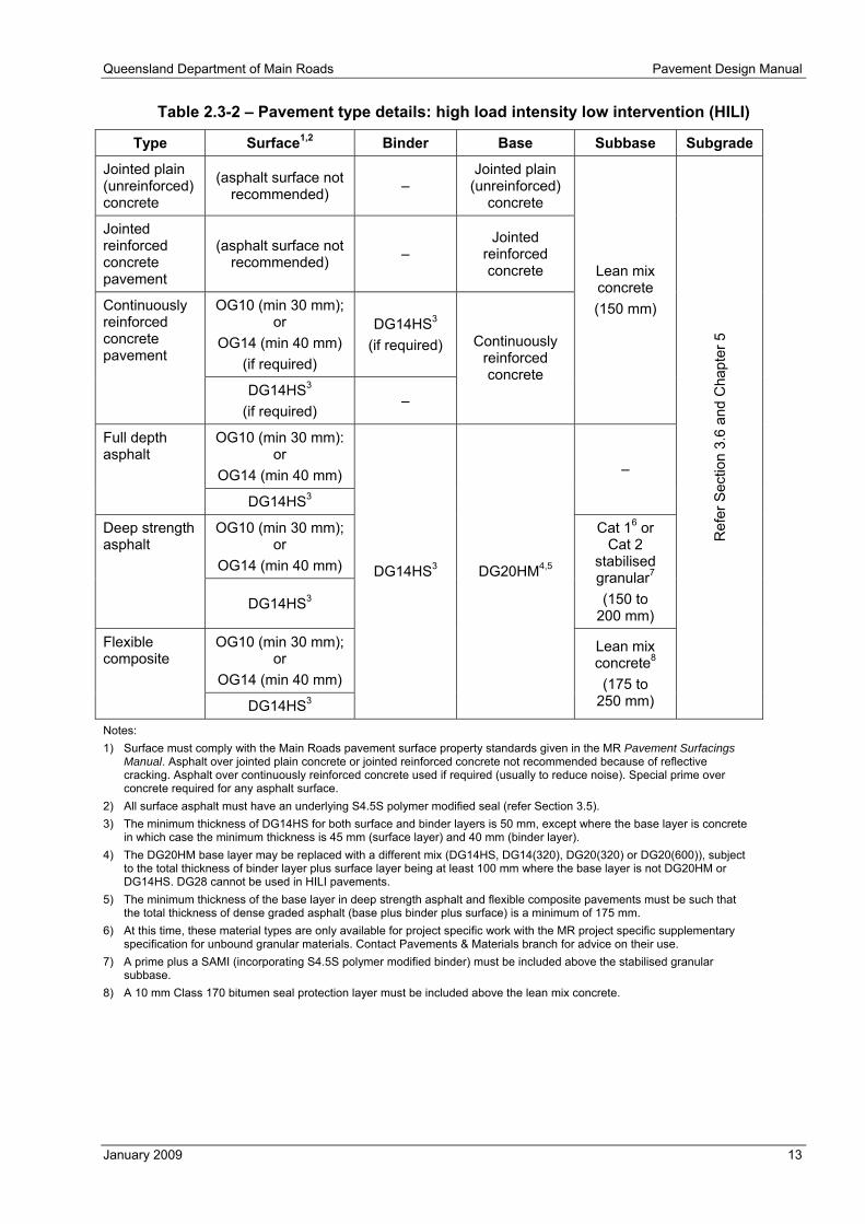
Table 2.3-2 – Pavement type details: high load intensity low intervention (HILI)
Type Surface1,2 Binder Base Subbase Subgrade
Jointed plain (unreinforced) concrete
(asphalt surface not recommended) –
Jointed plain (unreinforced)
concrete
Jointed reinforced concrete pavement
(asphalt surface not recommended) –
Jointed reinforced concrete
OG10 (min 30 mm); or
OG14 (min 40 mm) (if required)
DG14HS3
(if required)
Continuously reinforced concrete pavement
DG14HS3
(if required) –
Continuously reinforced concrete
Lean mix concrete (150 mm)
OG10 (min 30 mm): or
OG14 (min 40 mm)
Full depth asphalt
DG14HS3
–
OG10 (min 30 mm); or
OG14 (min 40 mm)
Deep strength asphalt
DG14HS3
Cat 16 or Cat 2
stabilised granular7 (150 to
200 mm)
OG10 (min 30 mm); or
OG14 (min 40 mm)
Flexible composite
DG14HS3
DG14HS3 DG20HM4,5
Lean mix concrete8 (175 to
250 mm) R
efer
Sec
tion
3.6
and
Cha
pter
5
Notes: 1) Surface must comply with the Main Roads pavement surface property standards given in the MR Pavement Surfacings
Manual. Asphalt over jointed plain concrete or jointed reinforced concrete not recommended because of reflective cracking. Asphalt over continuously reinforced concrete used if required (usually to reduce noise). Special prime over concrete required for any asphalt surface.
2) All surface asphalt must have an underlying S4.5S polymer modified seal (refer Section 3.5). 3) The minimum thickness of DG14HS for both surface and binder layers is 50 mm, except where the base layer is concrete
in which case the minimum thickness is 45 mm (surface layer) and 40 mm (binder layer). 4) The DG20HM base layer may be replaced with a different mix (DG14HS, DG14(320), DG20(320) or DG20(600)), subject
to the total thickness of binder layer plus surface layer being at least 100 mm where the base layer is not DG20HM or DG14HS. DG28 cannot be used in HILI pavements.
5) The minimum thickness of the base layer in deep strength asphalt and flexible composite pavements must be such that the total thickness of dense graded asphalt (base plus binder plus surface) is a minimum of 175 mm.
6) At this time, these material types are only available for project specific work with the MR project specific supplementary specification for unbound granular materials. Contact Pavements & Materials branch for advice on their use.
7) A prime plus a SAMI (incorporating S4.5S polymer modified binder) must be included above the stabilised granular subbase.
8) A 10 mm Class 170 bitumen seal protection layer must be included above the lean mix concrete.
Pavement Design Manual Queensland Department of Main Roads
14 January 2009
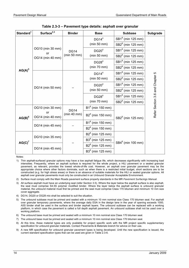
Table 2.3-3 – Pavement type details: asphalt over granular
Standard1 Surface2,3 Binder Base Subbase Subgrade
SB18 (min 125 mm) DG144 (min 50 mm) SB29 (min 125 mm)
SB18 (min 125 mm) DG204
(min 50 mm) SB29 (min 125 mm)
SB18 (min 125 mm)
OG10 (min 30 mm) or
OG14 (min 40 mm)
DG14
(min 50 mm)
DG284 (min 70 mm) SB29 (min 125 mm)
SB18 (min 125 mm) DG144 (min 50 mm) SB29 (min 125 mm)
SB18 (min 125 mm) DG204 (min 50 mm) SB29 (min 125 mm)
SB18 (min 125 mm)
AG(A)5
DG14 (min 50 mm) –
DG284 (min 70 mm) SB29 (min 125 mm)
B18 (min 150 mm) OG10 (min 30 mm) or
OG14 (min 40 mm)
DG14 (min 40 mm) B29 (min 150 mm)
B18 (min 150 mm) AG(B)6
DG14 (min 45 mm) – B29 (min 150 mm)
SB29 (min 125 mm)
B28 (min 125 mm) DG10 (min 35 mm)
B39 (min 125 mm)
B28 (min 125 mm) AG(C)7
DG14 (min 45 mm)
–
B39 (min 125 mm)
SB49 (min 100 mm)
Ref
er S
ectio
n 3.
6 an
d C
hapt
er 5
Notes: 1) Thin asphalt-surfaced granular options may have a low asphalt fatigue life, which decreases significantly with increasing load
intensities. Frequently, where an asphalt surface is required for the whole project, a HILI pavement or a sealed granular pavement, as relevant, provides the lowest whole-of-life cost. However, an asphalt over granular pavement may be the appropriate choice where other factors dominate, such as when there is a restricted initial budget, short sections are to be constructed (e.g. for high stress areas) or there is an absence of suitable materials for the HILI or sealed granular options. All asphalt over granular pavements must only be constructed in an Unbound Granular Acceptable Environment.
2) Surface must comply with the Main Roads pavement surface property standards in the MR Pavement Surfacings Manual. 3) All surface asphalt must have an underlying seal (refer Section 3.5). Where the layer below the asphalt surface is also asphalt,
the seal must comprise S4.5S polymer modified binder. Where the layer below the asphalt surface is unbound granular material, the unbound material must first be primed and the seal must comprise Class 170 bitumen and minimum 10 mm size cover aggregate.
4) DG14, DG20 or DG28 mix shall be selected to suit the situation. 5) The unbound subbase must be primed and sealed with a minimum 10 mm nominal size Class 170 bitumen seal. For asphalt
over granular temporary pavements, where the average daily ESA in the design lane in the year of opening exceeds 1000, A5S binder shall be used in the surface and binder asphalt layers. The unbound subbase can be replaced with a working platform, in which case the pavement is called a full depth asphalt pavement. An unbound subbase shall not be used over a working platform.
6) The unbound base must be primed and sealed with a minimum 10 mm nominal size Class 170 bitumen seal. 7) The unbound base must be primed and sealed with a minimum 10 mm nominal size Class 170 bitumen seal. 8) At this time, these material types are only available for project specific work with the MR project specific supplementary
specification for unbound granular materials. Contact Pavements & Materials branch for advice on their use. 9) A new MR specification for unbound granular pavement types is being developed. Until the new specification is issued, the
current standard specification types that can be used are given in Table 2.3-6.

Queensland Department of Main Roads Pavement Design Manual
January 2009 15
Table 2.3-4 – Pavement type details: sprayed seal granular
Minimum material quality4
Standard Project location1, 2 Surface3 Base Upper
subbase Lower
subbase
Subgrade
SG(A) AE sprayed seal B15 SB15 LSB15
SG(B) AE sprayed seal B2 SB2 LSB2
SG(C) AE sprayed seal B3 SB3 LSB3
AE sprayed seal B4 SB4 LSB4 SG(D) Low pavement
water-content sprayed seal B5 SB5 LSB5
Refer Section 3.6 and
Chapter 5
Notes: 1) AE: Unbound Granular Acceptable Environment (refer definitions). 2) In low pavement water-content environments the subbase layers can be assessed with an unsoaked CBR. 3) Surface must comply with the Main Roads pavement surface property standards given in the MR Pavement Surfacings
Manual. 4) A new MR specification for unbound granular pavement types is being developed. Until the new specification is issued, the
current standard specification types that can be used are given in Table 2.3-6. 5) At this time, these material types are only available for project specific work with the MR project specific supplementary
specification for unbound granular materials. Contact Pavements & Materials branch for advice on their use.

Pavement Design Manual Queensland Department of Main Roads
16 January 2009
Table 2.3-5 – Pavement type details: asphalt over stabilised granular
Standard Surface1,2 Binder Base Subbase Subgrade
DG145 Cat 16 or Cat 2
stabilised granular7 (150 to 200 mm)
DG205 Cat 16 or Cat 2
stabilised granular7 (150 to 200 mm)
OG10 (min 30 mm)
or OG14
(min 40 mm)
DG14 (min 45 mm)
DG285 Cat 16 or Cat 2
stabilised granular7 (150 to 200 mm)
DG145 Cat 16 or Cat 2
stabilised granular7 (150 to 200 mm)
DG205 Cat 16 or Cat 2
stabilised granular7 (150 to 200 mm)
ASt(A)3
DG14 (min 45 mm) –
DG285 Cat 16 or Cat 2
stabilised granular7 (150 to 200 mm)
OG10 (min 30 mm)
or OG14
(min 40 mm)
DG14 (min 50 mm)
Cat 16 or Cat 2 stabilised granular8
(min 150 mm)
ASt(B)4
DG14 (min 50 mm) –
Cat 15 or Cat 2 stabilised granular8
(min 150 mm)
–
Ref
er S
ectio
n 3.
6 an
d C
hapt
er 5
Notes: 1) Surface must comply with the Main Roads pavement surface property standards given in the MR Pavement Surfacings
Manual. 2) All surface asphalt must have an underlying S4.5S polymer modified seal (refer Section 3.5) 3) The minimum thickness of the base layer in ASt(A) pavements must be such that the total thickness of dense graded
asphalt (base plus binder plus surface) is a minimum of 175 mm. 4) Standard ASt(B) is only suitable for use as temporary pavement and not permanent pavement. Where the average daily
ESA in the design lane in the year of opening exceeds 1000, A5S binder shall be used in the surface and binder asphalt layers.
5) DG14, DG20 or DG28 mix shall be selected to suit the situation. 6) At this time, these material types are only available for project specific work with the MR project specific supplementary
specification for unbound granular materials. Contact Pavements & Materials branch for advice on their use. 7) A prime plus a SAMI (incorporating S4.5S polymer modified binder) must be included above the stabilised granular
subbase. 8) A prime and seal (minimum 14 mm nominal size with C170 bitumen) must be included above the stabilised granular base.
Queensland Department of Main Roads Pavement Design Manual
January 2009 17
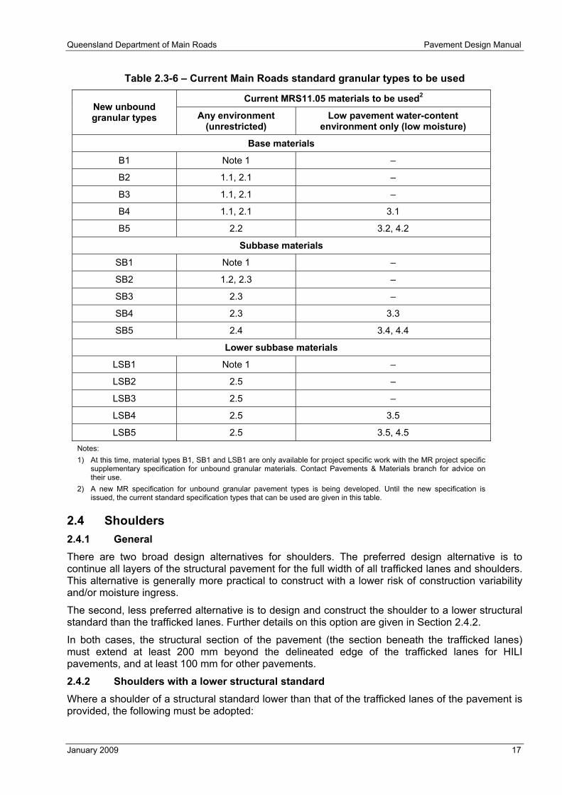
Table 2.3-6 – Current Main Roads standard granular types to be used
Current MRS11.05 materials to be used2 New unbound granular types Any environment
(unrestricted) Low pavement water-content
environment only (low moisture)
Base materials
B1 Note 1 –
B2 1.1, 2.1 –
B3 1.1, 2.1 –
B4 1.1, 2.1 3.1
B5 2.2 3.2, 4.2
Subbase materials
SB1 Note 1 –
SB2 1.2, 2.3 –
SB3 2.3 –
SB4 2.3 3.3
SB5 2.4 3.4, 4.4
Lower subbase materials
LSB1 Note 1 –
LSB2 2.5 –
LSB3 2.5 –
LSB4 2.5 3.5
LSB5 2.5 3.5, 4.5 Notes: 1) At this time, material types B1, SB1 and LSB1 are only available for project specific work with the MR project specific
supplementary specification for unbound granular materials. Contact Pavements & Materials branch for advice on their use.
2) A new MR specification for unbound granular pavement types is being developed. Until the new specification is issued, the current standard specification types that can be used are given in this table.
2.4 Shoulders 2.4.1 General There are two broad design alternatives for shoulders. The preferred design alternative is to continue all layers of the structural pavement for the full width of all trafficked lanes and shoulders. This alternative is generally more practical to construct with a lower risk of construction variability and/or moisture ingress.
The second, less preferred alternative is to design and construct the shoulder to a lower structural standard than the trafficked lanes. Further details on this option are given in Section 2.4.2.
In both cases, the structural section of the pavement (the section beneath the trafficked lanes) must extend at least 200 mm beyond the delineated edge of the trafficked lanes for HILI pavements, and at least 100 mm for other pavements.
2.4.2 Shoulders with a lower structural standard Where a shoulder of a structural standard lower than that of the trafficked lanes of the pavement is provided, the following must be adopted:
Pavement Design Manual Queensland Department of Main Roads
18 January 2009
a) Total pavement thickness of the shoulder shall be the same as the adjacent through lane.
b) Where the adjacent structural section of the pavement is full depth asphalt, deep strength asphalt or flexible composite, thick asphalt over granular or thick asphalt over stabilised pavement, the shoulder shall have the same asphalt surface, seal and binder courses as the structural section. Beneath this, the required thickness of asphalt base, or alternatively, a Type B1 or B2 unbound granular base with a polymer-modified seal, shall be designed to ensure that the asphalt does not fatigue. The balance of material down to the top of the working platform shall be at least a Type SB2 material. A pavement drain shall be provided at the interface of the two pavements.
c) Where the adjacent structural section of the pavement is asphalt surfaced granular or sealed granular pavement, the shoulder shall have the same asphalt surface course(s) and/or seal as the structural section. The shoulder shall also have the same granular base layer(s) and materials as the structural section. Other layers required to make up the design thickness for the shoulder are to be the same thickness and material type as used in the adjacent layers in the structural pavement. The balance of the thickness of the shoulder to the level of the lowest pavement layer is to be a select fill material. It must not be a general fill material.
d) Where the adjacent structural section of the pavement is concrete, the shoulder shall have the same asphalt surface, seal and binder courses (where they exist) as the structural section. The minimum total thickness of DG14HS shall be 100 mm. Beneath this, the required thickness of asphalt base, or alternatively, a Type B1 or B2 unbound granular base with a polymer-modified seal, shall be designed to ensure that the asphalt does not fatigue. The balance of material down to the top of the working platform shall be at least a Type SB2 material. A concrete edge drain shall be provided at the interface of the two pavements.
e) In all cases sealing is to continue to the outside edge of any verge or outside edge of the shoulder if a verge does not exist.
f) A lower standard shoulder is not permitted on the high side of one-way crossfalls as this could result in moisture entering the pavement.
Where a lower structural standard shoulder is constructed as a widening to an existing pavement, the effect of disturbing in situ subgrade materials should be considered in determining the thickness of the shoulder.
There are some limitations to the use of lower structural standard shoulders that need to be addressed when they are being considered for a particular project. These include the following:
● Construction may be more difficult because of increased complexity and narrow working widths.
● Future widening may be more difficult.
● With concrete pavements, a thicker base layer is required.
● Temporary trafficking of the shoulder during construction and future maintenance of the through lanes may be restricted by the lower structural capacity of the shoulder.
● Some shoulders may experience regular trafficking because of the nature of the road alignment (e.g. curves, end of tapers, narrow through lanes, access points, intersections and/or no edge lines).
2.4.3 Unsealed shoulders Where an unsealed shoulder is to be considered, the following requirements apply:
a) It cannot be used on any pavement with average daily ESA > 1000 in the design lane in the year of opening.
b) The seal must extend at least 200 mm beyond the delineated edge of the trafficked lane.

Queensland Department of Main Roads Pavement Design Manual
January 2009 19
c) The material in the shoulder must provide low permeability (max. 5 x 10⁻⁹ m/sec), low swell (max 1.5% at maximum dry density (MDD) and optimum moisture content (OMC) after ten days soaking) as well as sufficient strength to support traffic (minimum soaked CBR 40).
Because of the additional cost of the above shoulder material and the additional risk of loss of service life or failure caused by the infiltration of water, whole-of-life costing must be carefully assessed when unsealed shoulders are being considered.
Pavement Design Manual Queensland Department of Main Roads
20 January 2009
3 CONSTRUCTION AND MAINTENANCE CONSIDERATIONS
3.1 General The design procedures in this manual assume that construction and maintenance are carried out to the appropriate Main Roads standards. Unless such standards are met, the moduli, thicknesses and/or other critical properties assumed in the design model may not be achieved and reduced pavement performance could be expected.
3.2 Unbound granular Unbound granular pavements are particularly susceptible to damage caused by the infiltration of water resulting from: rain, water ponding and/or flooding during construction; water ponding and/or flooding during service; and lack of an adequate seal and/or drainage maintenance in service. Therefore:
● Projects including unbound granular material should be programmed such that construction of the pavement occurs at the time of year with the lowest likelihood of rain.
● Weather forecasts must be regularly reviewed and pavements not constructed when rain is likely and existing construction protected from the infiltration of water.
● Contract provisions must allow for delays to construction caused by wet weather.
Unbound granular pavements must not be used where:
● the pavement layer(s) cannot be constructed and maintained at less than their degree-of-saturation limits
● the subgrade cannot be constructed and maintained at the design modulus.
Contracts including the construction of unbound granular pavements must:
a) have allowances for work ceasing during periods of wet weather
b) establish clear responsibility and liability for infiltration of water during construction from sources including rain, surface and ground water flow, inundation/flooding, and transfer from new material with a high water content.
Unbound granular pavements in cuttings must have open table drains (see Figure 11.3-3).
During construction, rain gauges must be installed at least every 500 m along the job site. Rain events must be recorded daily to help determine the possible exposure of the pavement to water infiltration.
Where water does infiltrate granular material, destructive testing is required to assess the extent and change to water content and degree of saturation, and hence determine what action is required. Expensive re-work may be necessary to ensure the materials are brought within the specified limits before overlying materials are placed.
3.3 Stabilised materials Achieving the specified compaction standard in stabilised materials is essential for the development of the stiffness and fatigue characteristics assumed in design, particularly for the lower layers where maximum tensile stresses occur. To achieve the compaction standard, the maximum compacted thickness of a single layer is to be 200 mm.
Multi-layer construction should be avoided wherever possible as layers will eventually delaminate.
Multi-layer construction requires the provision of shear resistance (i.e. bonding) between layers to contribute to them acting together structurally.
Methods used to establish this for materials with a cementitious additive include:

Queensland Department of Main Roads Pavement Design Manual
January 2009 21
a) application of a cement slurry (water/cement ratio 0.6 to 0.7), at a rate equivalent to 2 kg of cement per square metre immediately before laying subsequent layers
b) placement of a prime and a seal with a large cover aggregate (> 14 mm) on top of the lower layer.
Where multi-layer construction is used:
a) The second and subsequent layers must not be stabilised with in situ stabilisation methods, even if the first layer is stabilised in situ.
b) The first layer should be constructed to be as thick as possible (compacted thickness of at least 150 mm but not greater than 200 mm) to avoid damage to the lower layer when placing subsequent layers. Where it is not possible to place a thick first layer, consideration should be given to retarding the first layer and placing the second layer before the first layer has set.
Multi-layer construction shall not be used for HILI pavements (the full thickness, between 150 mm and 200 mm, must be placed in one layer).
Reflection of shrinkage cracks must be expected where material with cementitious additive is used. In such situations, crack sealing maintenance work will be required.
3.4 Temporary connections for HILI pavements In order to reduce the risk of requiring frequent repairs in difficult to access locations (e.g. under heavy traffic), temporary connections for HILI pavements must be, as a minimum, asphalt over cement stabilised (ASt(B)) pavement or asphalt over granular (AG(A)) pavement.
3.5 Asphalt pavements Water contributes to stripping of the binder from the aggregate in asphalt pavements. To minimise this, a polymer modified binder seal must be provided beneath all asphalt surface layers in pavements where the layer beneath the surface layer is also asphalt. For effective waterproofing, the seal must have a minimum spray rate of 1.2 litres per square metre and cover aggregate with minimum nominal size of 10 mm. At locations subject to heavy braking and/or tight cornering, such as intersections, roundabouts and approaches, excluding the seal can reduce the risk of shearing, but increase the risk of stripping of lower layers. Provision of a seal in these locations is not mandated. If a seal is provided the spray rate should be reduced to 1.0 to 1.2 litres per square metre to reduce the risk of shearing.
The binder for the waterproofing seal shall be an S4.5S polymer modified binder.
Use of SBS polymer modified binder in the asphalt can also help minimise stripping.
Moisture ingress during construction can lead to stripping. Dense graded asphalt mixes of 20 mm nominal size or larger are particularly prone to moisture ingress. To reduce the risk of moisture ingress, construction sequencing should not leave DG20 layers exposed for more than ten calendar days and DG28 layers must not be left exposed for more than two calendar days. If this is unavoidable, a seal or minimum 50 mm DG14 layer should be placed to provide protection from moisture ingress.
3.6 Working platform A working platform must be used for all HILI and ASt(A) pavements and is recommended for all other pavements with average daily ESA ≥ 1000 in the design lane in the year of opening.
A working platform must be used for all temporary pavements where the design subgrade CBR is less than 5%.
The working platform is located below the lowest pavement layer. Its function is to provide:
a) access for construction traffic

Pavement Design Manual Queensland Department of Main Roads
22 January 2009
b) a sound platform on which to construct the pavement layers
c) protection to the subgrade for the life of the pavement.
The design, construction and maintenance of the working platform are the responsibility of the Contractor, but must include the specified in-service requirements given in Section 5.5. The in-service requirements are for the sole purpose of providing a satisfactory substrate layer for the full service life of the pavement.
3.7 Settlement Neither this manual nor Part 2 of the Austroads guide include provisions to deal with settlement below the pavement layers. Where required, additional geotechnical investigations and assessments shall be carried out to determine if and how much settlement may occur. If settlement is likely, pre-treatment (e.g. drainage and/or surcharge of the formation) is required to reduce the extent of settlement after the pavement is constructed.
3.8 Moisture ingress and maintenance Pavement surface courses, seals and all drainage must be adequately maintained. Failure to maintain seals and drainage will cause, at least, loss of service life in most pavements and at worst, failure. Unbound granular pavements are particularly susceptible to loss of service life and failure caused by the infiltration of water.
Rain following a long period of dry weather is particularly hazardous because:
a) During long periods of dry weather there may be no stimulus to adequately maintain seals and drainage in a budget constrained environment, which could result in pavements that are not protected upon the onset of wet weather.
b) Shrinkage of materials may generate cracks that will allow rapid entry of water.
3.9 Trafficking of incomplete pavement Pavement damage resulting from temporarily trafficking pavement layers below the final surface must be included in the pavement design calculations.
3.10 Thickness of bituminous seals For the purpose of determining survey levels, the thickness of seals and primerseals shall be taken as the average least dimension (ALD) of the cover aggregate. If the ALD is not known at the time of design, the ALD can be estimated as 6 mm for 10 mm nominal size cover aggregate and 9 mm for 14 mm nominal size cover aggregate.

Queensland Department of Main Roads Pavement Design Manual
January 2009 23
4 ENVIRONMENT
4.1 General Water and temperature have a major effect on pavement performance. Temperature directly affects the performance of seals, asphalt and concrete, and water directly affects the performance of unbound granular pavements and subgrades. Water can also affect asphalt. Knowledge of environmental conditions is essential for the design, construction and maintenance of pavements.
4.2 Climatic zones Figure 4.2-1 illustrates Australian climatic zones on the basis of temperature and humidity. Most of coastal Queensland is classified as having hot humid summers. Western areas have hot dry summers with either mild or cold winters. Further information on climate zones and climate averages is available from the Commonwealth Bureau of Meteorology at www.bom.gov.au.
Figure 4.2-1 –Australian climatic zones (www.bom.gov.au)
Figure 4.2-2 illustrates Australian seasonal rainfall zones.

Pavement Design Manual Queensland Department of Main Roads
24 January 2009
Figure 4.2-2 – Australian seasonal rainfall zones (www.bom.gov.au)
4.3 Water environment Average annual rainfall and evaporation rates for Queensland are shown in Figure 4.3-1 and Figure 4.3-2.
Figure 4.3-1 – Average annual rainfall for Queensland (www.bom.gov.au)

Queensland Department of Main Roads Pavement Design Manual
January 2009 25
Figure 4.3-2 – Average annual evaporation for Australia (www.bom.gov.au)
In the 1950s, C. W. Thornthwaite, Professor of Climatology at John Hopkins University, introduced a method to study the climate synthetically, which combined rainfall and Potential Evapotranspiration (PET).
PET represents the water quantity that soil would lose because of surface evaporation and plant transpiration in an environment where continuous soil water storage exists. When PET is exactly balanced by rainfall over the year and water is available, there is neither a deficit (d) nor surplus (s) of water.
Thornthwaite defined a total moisture index (MI) as shown in Equation 4-1.
Equation 4-1
100 ( )s dMIPET× −
=
It follows that when rainfalls are lower than PET, MI is negative and the climate is dry. When rainfalls are higher than PET, the MI is positive and climate is wet. The climate classification based on MI is given in Table 4.3-1.
Figure 4.3-3 shows the MI values for Queensland. A comparison between Figure 4.3-1 and Figure 4.3-2 shows that regions with a rainfall below 600 mm have a negative MI and hence are dry as the evapotranspiration exceeds the rainfall. Areas with an annual rainfall less than 500 mm are semi-arid.

Pavement Design Manual Queensland Department of Main Roads
26 January 2009
Table 4.3-1 – Climatic types according to the total moisture index (MI)
Symbol Climatic type MI
A Very humid Over 100
B4 Humid 80 to100
B3 Humid 60 to 80
B2 Humid 40 to 60
B1 Humid 20 to 40
C2 Sub-humid 0 to 20
C1 Sub-dry -33 to -0
D Semi-arid -66 to -33
E Dry -110 to -66
Figure 4.3-3 – Thornthwaite moisture index for Queensland
(contours at intervals of 5 units)
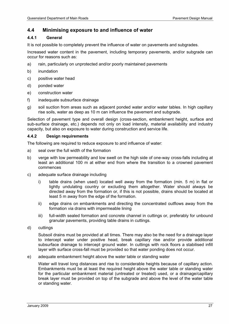
Queensland Department of Main Roads Pavement Design Manual
January 2009 27
4.4 Minimising exposure to and influence of water 4.4.1 General It is not possible to completely prevent the influence of water on pavements and subgrades.
Increased water content in the pavement, including temporary pavements, and/or subgrade can occur for reasons such as:
a) rain, particularly on unprotected and/or poorly maintained pavements
b) inundation
c) positive water head
d) ponded water
e) construction water
f) inadequate subsurface drainage
g) soil suction from areas such as adjacent ponded water and/or water tables. In high capillary rise soils, water as deep as 10 m can influence the pavement and subgrade.
Selection of pavement type and overall design (cross-section, embankment height, surface and sub-surface drainage, etc.) depends not only on load intensity, material availability and industry capacity, but also on exposure to water during construction and service life.
4.4.2 Design requirements The following are required to reduce exposure to and influence of water:
a) seal over the full width of the formation
b) verge with low permeability and low swell on the high side of one-way cross-falls including at least an additional 100 m at either end from where the transition to a crowned pavement commences
c) adequate surface drainage including
i) table drains (when used) located well away from the formation (min. 5 m) in flat or lightly undulating country or excluding them altogether. Water should always be directed away from the formation or, if this is not possible, drains should be located at least 5 m away from the edge of the formation.
ii) edge drains on embankments and directing the concentrated outflows away from the formation via drains with impermeable lining
iii) full-width sealed formation and concrete channel in cuttings or, preferably for unbound granular pavements, providing table drains in cuttings.
d) cuttings
Subsoil drains must be provided at all times. There may also be the need for a drainage layer to intercept water under positive head, break capillary rise and/or provide additional subsurface drainage to intercept ground water. In cuttings with rock floors a stabilised infill layer with surface cross-fall must be provided so that water ponding does not occur.
e) adequate embankment height above the water table or standing water
Water will travel long distances and rise to considerable heights because of capillary action. Embankments must be at least the required height above the water table or standing water for the particular embankment material (untreated or treated) used, or a drainage/capillary break layer must be provided on top of the subgrade and above the level of the water table or standing water.
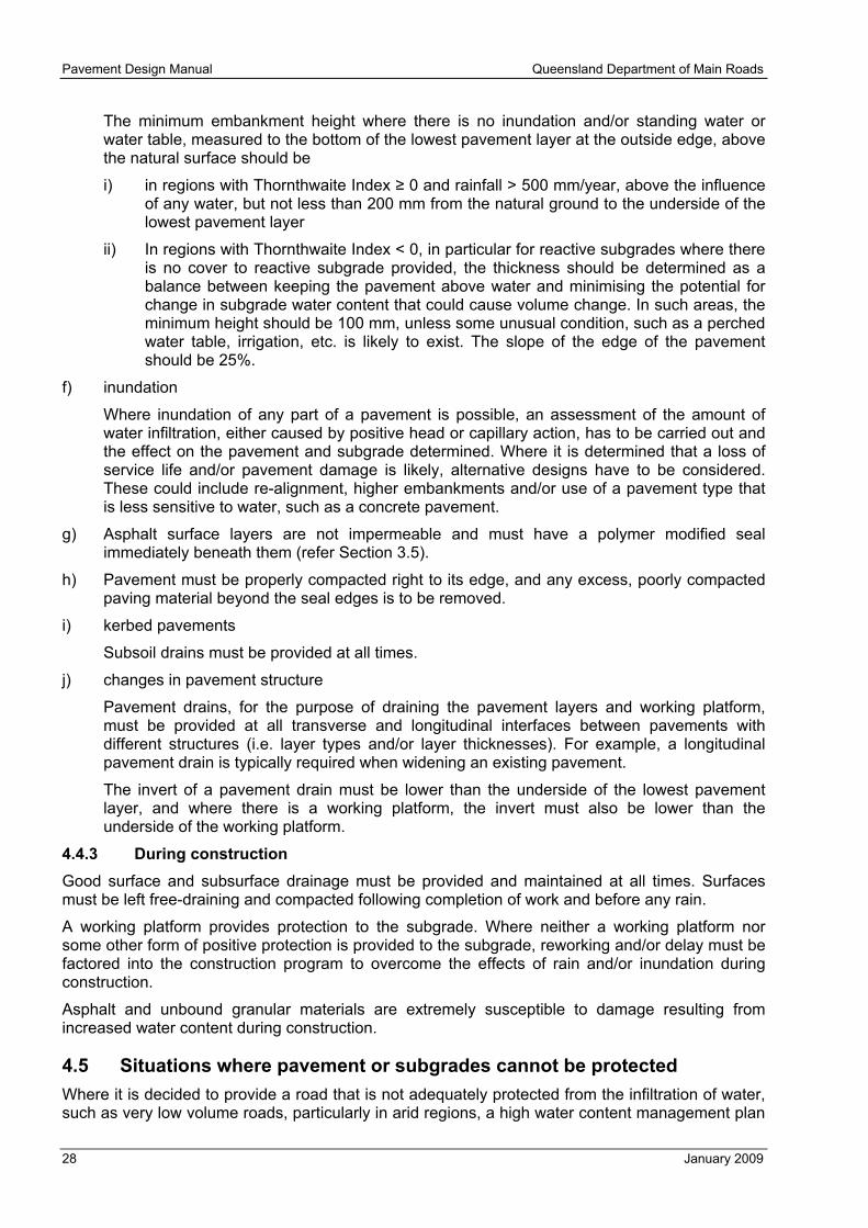
Pavement Design Manual Queensland Department of Main Roads
28 January 2009
The minimum embankment height where there is no inundation and/or standing water or water table, measured to the bottom of the lowest pavement layer at the outside edge, above the natural surface should be
i) in regions with Thornthwaite Index ≥ 0 and rainfall > 500 mm/year, above the influence of any water, but not less than 200 mm from the natural ground to the underside of the lowest pavement layer
ii) In regions with Thornthwaite Index < 0, in particular for reactive subgrades where there is no cover to reactive subgrade provided, the thickness should be determined as a balance between keeping the pavement above water and minimising the potential for change in subgrade water content that could cause volume change. In such areas, the minimum height should be 100 mm, unless some unusual condition, such as a perched water table, irrigation, etc. is likely to exist. The slope of the edge of the pavement should be 25%.
f) inundation
Where inundation of any part of a pavement is possible, an assessment of the amount of water infiltration, either caused by positive head or capillary action, has to be carried out and the effect on the pavement and subgrade determined. Where it is determined that a loss of service life and/or pavement damage is likely, alternative designs have to be considered. These could include re-alignment, higher embankments and/or use of a pavement type that is less sensitive to water, such as a concrete pavement.
g) Asphalt surface layers are not impermeable and must have a polymer modified seal immediately beneath them (refer Section 3.5).
h) Pavement must be properly compacted right to its edge, and any excess, poorly compacted paving material beyond the seal edges is to be removed.
i) kerbed pavements
Subsoil drains must be provided at all times.
j) changes in pavement structure
Pavement drains, for the purpose of draining the pavement layers and working platform, must be provided at all transverse and longitudinal interfaces between pavements with different structures (i.e. layer types and/or layer thicknesses). For example, a longitudinal pavement drain is typically required when widening an existing pavement.
The invert of a pavement drain must be lower than the underside of the lowest pavement layer, and where there is a working platform, the invert must also be lower than the underside of the working platform.
4.4.3 During construction Good surface and subsurface drainage must be provided and maintained at all times. Surfaces must be left free-draining and compacted following completion of work and before any rain.
A working platform provides protection to the subgrade. Where neither a working platform nor some other form of positive protection is provided to the subgrade, reworking and/or delay must be factored into the construction program to overcome the effects of rain and/or inundation during construction.
Asphalt and unbound granular materials are extremely susceptible to damage resulting from increased water content during construction.
4.5 Situations where pavement or subgrades cannot be protected Where it is decided to provide a road that is not adequately protected from the infiltration of water, such as very low volume roads, particularly in arid regions, a high water content management plan

Queensland Department of Main Roads Pavement Design Manual
January 2009 29
solution may be adopted with the approval of the General Manager (Engineering & Technology). This involves monitoring the pavement after rain and/or inundation and/or when water has been standing and, if necessary, restricting the movement of traffic. Restrictions could include traffic limitations on the outside edge of the pavement, restricted loads and so on, until the pavement and subgrade have dried. This relaxation in design must not be applied to roads with average daily ESA > 100 in the design lane in the year of opening.
For all other cases, a concrete or asphalt surfaced concrete pavement must be provided with a design subgrade strength that reflects the measures to control volume change as per Clause 5.3.
4.6 Temperature environment The effect of temperature on asphalt is incorporated into the design method through the use of the Weighted Mean Annual Pavement Temperature (WMAPT) for the project location. The WMAPTs for various sites in Queensland are listed in Appendix 2 of this manual.
Unbound granular pavements, except for seals, are normally not influenced by temperature.
The influence of temperature has been accommodated in the specifications for concrete pavements. However, during construction the whole concrete pavement cross-section must be completed within a month to minimise problems generated by differential movement.
In Flexible Composite pavements, the asphalt must be placed within a month of placement of the lean mix concrete subbase. If this is not possible, a SAMI must be provided above the lean mix concrete subbase, prior to placing any asphalt, as wide shrinkage cracks may occur.

Pavement Design Manual Queensland Department of Main Roads
30 January 2009
5 SUBGRADE
5.1 General The subgrade can comprise alternatives including one or a combination of the following:
a) working platform
b) capping layer
c) drainage layer
d) select fill
e) general fill
f) treated in situ material
g) natural unprocessed in situ material, other than that moved from another location and/or compacted.
In pavement thickness design calculations, fill and/or in situ untreated subgrade materials to a minimum depth of 1.5 metres below the underside of the lowest pavement layer must be included.
This manual describes soils according to the Unified Soil Classification System, which uses a two-letter code to indicate soils classification (refer Appendix 1).
5.2 Subgrade assessment 5.2.1 General The untreated subgrade has to be assessed for the following:
a) suitability of embankment material for the design and conformance to specifications
b) suitability of in situ material for any necessary treatments and the subgrade design modulus to permit the design of the pavement.
Testing of subgrade materials to determine design inputs shall be undertaken in the planning and design phase.
Subgrade assessment can be made difficult by highly variable natural materials and changes to the subgrade material during construction. Accordingly, the subgrade materials must be reassessed immediately prior to pavement construction, in addition to any prior assessments. The pavement design as a whole must also be subsequently reassessed and amended to reflect any change. Where prior assessment has been adequate, few changes should be required. Allowances must be made in the construction contract for changes to the pavement design and changes to subgrade treatments during the construction phase.
The requirements for subgrade testing prior to pavement construction also apply to temporary pavements.
Subgrade samples shall be selected and tested for:
a) plastic limit
b) liquid limit
c) in situ moisture content
d) percent passing the AS 0.425 mm sieve
e) weighted plasticity index (WPI), which is the plastic limit multiplied by the percent passing the AS 0.425 mm sieve

Queensland Department of Main Roads Pavement Design Manual
January 2009 31
f) california bearing ratio (CBR) and swell determined at the density and moisture content as provided in Section 5.2.2.
The in situ untreated subgrade shall also be tested with a dynamic cone penetrometer (DCP).
Where there is to be any subgrade stabilisation, the subgrade shall be tested in accordance with AS1289.4.2.1 Soil Chemical Tests – Determination of the sulphate content of a natural soil and the sulphate content of the groundwater-Normal method. The soluble sulphate content shall not exceed 0.2%.
Many extremely weathered and highly weathered rocks in Queensland (especially sedimentary rocks such as siltstone, mudstone and shale) tend to break down during construction to form moisture-sensitive silts and clays. For such subgrade materials, the effects of construction should be simulated by either repeated cycles of compacting the material or other forms of pre-treatment, prior to compacting the specimens for testing.
A typical pre-treatment is crushing to the size specified for selected material, then artificial weathering by 10 cycles of soaking for 18–20 hours followed by drying on a hot plate but without baking, and finally 3 cycles of standard proctor compaction at just under optimum moisture content.
5.2.2 Laboratory CBR test conditions CBR testing of in situ untreated subgrade and fill material to determine the design CBR and swell shall comprise single point CBR tests in accordance with Q113C. Testing shall target at most 95.0% maximum dry density (MDD) and 100% optimum moisture content (OMC) using standard compactive effort. The target MDD for testing can be increased to 97.0% for Class A and Class B fill materials.
Soaking periods for determining both CBR and swell shall be as follows:
a) testing under ten-day soaked CBR conditions must be undertaken in the following circumstances
i) floodways, causeways and other pavements likely to be inundated
ii) cuttings at or below the water table level that existed prior to the cutting or where seepage is likely
iii) locations where the water table is sufficiently close to the top of the subgrade to influence the water content of the subgrade and/or pavement materials
iv) urban areas where infiltration from kerb and channel or unsealed medians is likely
v) areas with a Thornthwaite Index ≥ 0
vi) situations where factors such as high rainfall and high traffic volume and/or previous experience indicate that soaked conditions should apply.
b) un-soaked for low pavement water-content environments
c) four-day soaked for locations with circumstances not described under points a) or b) above.
5.2.3 Statistical analysis of CBR data When a statistical analysis of CBR data is used to determine the design CBR, this is to be undertaken by calculating the lower 10th percentile of the laboratory CBR test results and the lower 10th percentile of the DCP test results. The design CBR is then the minimum of these two values.
Use of an average CBR value for design is not appropriate.
5.2.4 Adoption of presumptive CBR values Several MR Regions have considerable experience and performance data on specific soil types in local climatic and topographic conditions. Use of this information reduces the cost of subgrade evaluation and also helps ensure a consistent approach to the determination of subgrade CBR within the local area.

Pavement Design Manual Queensland Department of Main Roads
32 January 2009
Use of this approach involves the assessment of subgrades on the basis of geological, topographic and drainage information, together with regular routine soil classification tests. Once these factors are assessed, a presumptive design CBR is assigned on the basis of previous test data and performance for similar soils in similar conditions.
5.2.5 Variation in subgrade support with moisture changes There are numerous factors affecting the moisture content of the subgrade throughout the life of the pavement. It is therefore often difficult to predict with certainty what the actual operating moisture content will be. For example seepage from higher ground, either along the pavement or within cuts, can cause fluctuations in subgrade moisture conditions. Thus, in determining the likely in-service moisture content, some error is quite possible.
In order to determine the possible consequences of any error, the sensitivity of the subgrade strength/stiffness to changes in moisture content should be considered. In general, the following comments apply:
a) sandy (SW, SP) soils
Small fluctuations in water content produce little change in volume or strength/stiffness.
b) silty (SM, SC, ML) soils
Small fluctuations in water content produce little change in volume, but may produce large changes in strength/stiffness. Typically these soils attract and retain water through capillary action, and do not drain well.
c) CL or CH clay
Small fluctuations in water content may produce large variations in volume, and there may be large changes in strength/stiffness, particularly if the moisture content is near or above optimum. Typically these soils attract and retain water through matrix suction.
Moisture from seepage, infiltration through the surface, and water table fluctuations can be controlled by installing properly designed pavement and subsoil drains. However, subsoil drains are effective only when subgrade moisture is subject to hydrostatic head (positive pore pressures). It is not uncommon in wet regions for fine grained subgrade materials (silts and clays) to have equilibrium moisture content above optimum moisture content (standard compactive effort). However, because pore pressures are not positive, they cannot be drained. While subsurface drainage does play an important role in moisture control, care must be taken not to make unrealistic assumptions about the effect of subsurface drains on subgrade moisture condition.
5.3 Subgrade water-induced volume change 5.3.1 General As a consequence of changes in water content, subgrades with reactive clays (including embankments where reactive clays have not been excluded), can experience considerable volume change that can disrupt the pavement in a number of ways, including:
a) surface deformation, causing increased roughness and potential ponding of water
b) pavement deformation, that can cause loss of density and loss of strength
c) cracking that can allow the infiltration of contaminants (such as water and incompressible material) and also loss of strength, particularly fatigue capacity.
A whole-of-life assessment (refer Section 10) should be carried out to determine the most appropriate action to address potential volume change. Options can include one or a combination of the following:
a) reducing entry of water
b) reducing volume change
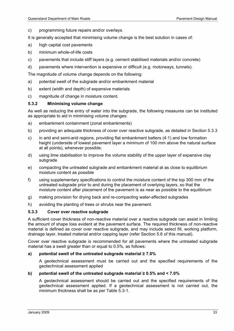
Queensland Department of Main Roads Pavement Design Manual
January 2009 33
c) programming future repairs and/or overlays.
It is generally accepted that minimising volume change is the best solution in cases of:
a) high capital cost pavements
b) minimum whole-of-life costs
c) pavements that include stiff layers (e.g. cement stabilised materials and/or concrete)
d) pavements where intervention is expensive or difficult (e.g. motorways, tunnels).
The magnitude of volume change depends on the following:
a) potential swell of the subgrade and/or embankment material
b) extent (width and depth) of expansive materials
c) magnitude of change in moisture content.
5.3.2 Minimising volume change As well as reducing the entry of water into the subgrade, the following measures can be instituted as appropriate to aid in minimising volume changes:
a) embankment containment (zonal embankments)
b) providing an adequate thickness of cover over reactive subgrade, as detailed in Section 5.3.3
c) in arid and semi-arid regions, providing flat embankment batters (4:1) and low formation height (underside of lowest pavement layer a minimum of 100 mm above the natural surface at all points), whenever possible;
d) using lime stabilisation to improve the volume stability of the upper layer of expansive clay subgrade
e) compacting the untreated subgrade and embankment material at as close to equilibrium moisture content as possible
f) using supplementary specifications to control the moisture content of the top 300 mm of the untreated subgrade prior to and during the placement of overlying layers, so that the moisture content after placement of the pavement is as near as possible to the equilibrium
g) making provision for drying back and re-compacting water-affected subgrades
h) avoiding the planting of trees or shrubs near the pavement.
5.3.3 Cover over reactive subgrade A sufficient cover thickness of non-reactive material over a reactive subgrade can assist in limiting the amount of shape loss evident at the pavement surface. The required thickness of non-reactive material is defined as cover over reactive subgrade, and may include select fill, working platform, drainage layer, treated material and/or capping layer (refer Section 5.6 of this manual).
Cover over reactive subgrade is recommended for all pavements where the untreated subgrade material has a swell greater than or equal to 0.5%, as follows:
a) potential swell of the untreated subgrade material ≥ 7.0% A geotechnical assessment must be carried out and the specified requirements of the geotechnical assessment applied
b) potential swell of the untreated subgrade material ≥ 0.5% and < 7.0% A geotechnical assessment should be carried out and the specified requirements of the geotechnical assessment applied. If a geotechnical assessment is not carried out, the minimum thickness shall be as per Table 5.3-1.

Pavement Design Manual Queensland Department of Main Roads
34 January 2009
Provision of minimum cover over reactive subgrade is mandatory for HILI pavements. For all other pavements the minimum cover is recommended but may be reduced where this decision is justifiable based on acceptance of reduced performance and whole-of-life cost considerations.
Table 5.3-1 – Cover over reactive subgrade
Untreated subgrade swell (%) Minimum cover over reactive subgrade (mm)
≥ 7.0 Geotechnical assessment required
≥ 5.0 to < 7.0 1000
≥ 2.5 to < 5.0 600
≥ 0.5 to < 2.5 150
A geotechnical assessment means assessment and advice from a geotechnical engineer. Their assessment is likely to include shallow boreholes, with continuous undisturbed sampling, to allow the extents of expansive material, shrink swell index testing, moisture content variations, suction testing and x-ray diffraction testing to be determined. A review of the maintenance history and condition of existing pavements and structures should also be undertaken.
5.4 Select fill and treated material When used as cover over reactive subgrade, the required material properties for select fill and treated materials (in addition to the requirements in the Standard Specifications) are given in Table 5.4-1.
Table 5.4-1 – Material properties for select fill and treated material
Depth below the working platform1 Property
≤ 150 mm > 150 mm
Laboratory CBR (%) 2 ≥ 10 ≥ 10
Maximum aggregate size (mm) 75 75
Weighted plasticity index (WPI) < 1200 < 2200
Swell (%) 2 ≤ 0.5 ≤ 2.5
% passing 0.075 mm 4–30 inclusive 4–30 inclusive
Plasticity index (PI) > 4 > 4 Notes: 1) Where there is no working platform, this is the depth below the bottom of the lowest pavement layer. 2) Tested in accordance with Q113C (97.0% MDD, OMC, standard compactive effort) and soaked for a period of ten days.
Material may be chosen with a minimum CBR greater than specified above, up to 15%, if this is considered to provide a better overall design solution.
5.5 Working platform Refer to Section 3.6 of this manual to determine where a working platform is required.
5.5.1 In-service requirements The working platform is required to meet the following minimum standards necessary for it to function when it becomes part of the subgrade for the operating service life of the pavement structure:
a) be comprised of plant mixed stabilised granular material of a standard no less than Type SB2, with a minimum 2.0% of either cement, blended cement or cementitious blend
b) a UCS of 1.5 ± 0.5 MPa at seven days

Queensland Department of Main Roads Pavement Design Manual
January 2009 35
c) at least 150 mm (compacted) thickness
d) primed (AMC0) and sealed (10 mm aggregate, Class 170 bitumen) so that its surface is waterproof, safe and adequate for the Contractor’s operations
e) have a surface maintained with a geometric tolerance of ±10 mm of the specified height and a maximum deviation from a 3 m straight edge of 8 mm at all points on the surface.
The above requirements are a minimum only for the purpose of providing a layer beneath the final pavement, and are not necessarily sufficient for a working platform subject to construction traffic or a construction platform for the pavement layers. In addition to the above requirements, the Contractor shall determine what, if any, other standards are needed to meet the Contractor’s design requirements listed in Section 5.5.2.
5.5.2 Contractor’s design requirements As a minimum, the working platform must satisfy the requirements of Section 5.5.1. In addition, the working platform shall be designed by the Contractor to meet the particular requirements of the project including, but not limited to, the following considerations:
a) the characteristics of the underlying subgrade materials
b) the environment including, but not limited to, rainfall, temperature, surface and sub-surface water conditions including location of the water table and standing water, surface sources of water and drainage, and sub-surface sources of water and drainage
c) the Contractor’s construction traffic and equipment the Contractor intends to use to construct the pavement and other works
d) the full operating life of the working platform including, but not limited to
i) actual period during which the working platform will be required to provide access for construction traffic
ii) actual periods during which the working platform will be required to provide a platform for construction traffic and equipment, including for construction of the pavement layers
iii) actual periods during which it is not in use prior to the construction of the overlying pavement
e) provide protection to the underlying layers, including protection from water and stress
f) provide a platform for the construction of the overlying pavement
g) suitability for the Contractor’s construction program
h) meet in-service requirements as specified in Section 5.5.1 for the overlying pavement structure
i) be sufficiently stiff to enable the placement and compaction of the overlying pavement layers in accordance with their specified requirements.
As part of the design of the pavement and earthworks, the height of the top and bottom of the working platform shall be specified based on a working platform thickness of 150 mm. If the Contractor requires a working platform thicker than 150 mm, this can be achieved by either or both of the following:
a) reducing the thickness of the select fill material, if present
b) excavating the subgrade.
5.6 Capping Capping shall be provided where the in situ untreated subgrade has a design CBR < 3.0%. The required capping thickness is given in Table 5.6-1. For subgrade design CBR ≤ 1.0%, a specific assessment is required.
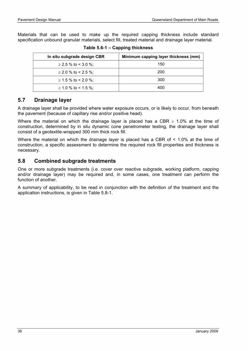
Pavement Design Manual Queensland Department of Main Roads
36 January 2009
Materials that can be used to make up the required capping thickness include standard specification unbound granular materials, select fill, treated material and drainage layer material.
Table 5.6-1 – Capping thickness
In situ subgrade design CBR Minimum capping layer thickness (mm)
≥ 2.5 % to < 3.0 %; 150
≥ 2.0 % to < 2.5 %; 200
≥ 1.5 % to < 2.0 %; 300
≥ 1.0 % to < 1.5 %; 400
5.7 Drainage layer A drainage layer shall be provided where water exposure occurs, or is likely to occur, from beneath the pavement (because of capillary rise and/or positive head).
Where the material on which the drainage layer is placed has a CBR ≥ 1.0% at the time of construction, determined by in situ dynamic cone penetrometer testing, the drainage layer shall consist of a geotextile-wrapped 300 mm thick rock fill.
Where the material on which the drainage layer is placed has a CBR of < 1.0% at the time of construction, a specific assessment to determine the required rock fill properties and thickness is necessary.
5.8 Combined subgrade treatments One or more subgrade treatments (i.e. cover over reactive subgrade, working platform, capping and/or drainage layer) may be required and, in some cases, one treatment can perform the function of another.
A summary of applicability, to be read in conjunction with the definition of the treatment and the application instructions, is given in Table 5.8-1.

Queensland Department of Main Roads Pavement Design Manual
January 2009 37
Table 5.8-1 – Subgrade treatment guide
CBR (%) ≥ 3.0 < 3.0 1
Swell (%) < 0.5 ≥ 0.5 < 0.5 ≥ 0.5 In situ subgrade conditions
Water exposure2 No Yes No Yes No Yes No Yes
Working platform3
Cover over reactive subgrade
Capping
Treatments required (Required if shaded)
Drainage layer
Combined treatment category CT1 CT2 CT3 CT4 CT5 CT6 CT7 CT8 Notes: 1) For CBR ≤ 1.0%, the composition and thickness of the capping is subject to a specific assessment. 2) Water exposure is determined by assessing whether water flow from an internal and/or external source and/or soil
suction effects from a high water table can adversely affect the properties of the pavement and/or the working platform, capping, select fill and/or treated material.
3) A working platform is to be included if required. Refer to Section 3.6 of this manual.
Applications of the combined treatment categories are described below.
Category CT1 – Working platform (if required) Refer to Section 3.6 of this manual to determine if a working platform is required.
Category CT2 – Working platform (if required) plus drainage layer In this case, neither treatment can perform the function of the other. Hence, both working platform (if required) and drainage layer are necessary. If a working platform exists, it is placed on top of the drainage layer.
Category CT3 – Working platform (if required) plus cover over reactive subgrade The thickness of the working platform (if it exists) contributes to satisfying the required cover over reactive subgrade thickness.
If the working platform thickness is greater than or equal to the required cover over reactive subgrade thickness, no additional thickness of material is necessary to satisfy the cover over reactive subgrade requirement. Therefore, the only treatment required is a working platform.
If the working platform thickness is less than the required cover over reactive subgrade thickness, then additional thickness of material is necessary to satisfy the cover over reactive subgrade requirement. The additional material can be additional working platform, select fill and/or treated material.
Category CT4 – Working platform (if required) plus cover over reactive subgrade plus drainage layer The thicknesses of the working platform (if it exists) and drainage layer contribute to satisfying the required cover over reactive subgrade thickness.
If the total thickness of the working platform plus drainage layer is greater than or equal to the required cover over reactive subgrade thickness, no additional thickness of material is necessary to satisfy the cover over reactive subgrade requirement. Therefore, the treatment required is a working platform placed on top of a drainage layer.
If the total thickness of the working platform plus drainage layer is less than the required cover over reactive subgrade thickness, then additional thickness of material is necessary to satisfy the cover over reactive subgrade requirement. The additional material can be additional working platform, drainage layer, select fill and/or treated material.

Pavement Design Manual Queensland Department of Main Roads
38 January 2009
Category CT5 – Working platform (if required) plus capping In this case, neither treatment can perform the function of the other. Hence, both working platform (if required) and capping are necessary. If a working platform exists, it is placed on top of the capping.
Category CT6 – Working platform (if required) plus capping plus drainage layer The thickness of the drainage layer contributes to satisfying the required capping thickness.
If the thickness of the drainage layer is greater than or equal to the required capping thickness, no additional thickness of material is necessary to satisfy the capping requirement. Therefore, the treatment required is a working platform placed on top of a drainage layer.
If the thickness of the drainage layer is less than the required capping thickness, then additional thickness of material is necessary to satisfy the capping requirement. The additional material can be additional drainage layer, or other suitable capping material (refer Section 5.6) placed on top of the drainage layer.
Category CT7 – Working platform (if required) plus capping plus cover over reactive subgrade The thicknesses of the working platform (if it exists) and capping contribute to satisfying the required cover over reactive subgrade thickness.
If the total thickness of the working platform plus capping is greater than or equal to the required cover over reactive subgrade thickness, no additional thickness of material is necessary to satisfy the cover over reactive subgrade requirement. Therefore, the treatment required is a working platform placed on top of the capping.
If the total thickness of the working platform plus capping is less than the required cover over reactive subgrade thickness, then additional thickness of material is necessary to satisfy the cover over reactive subgrade requirement. The additional material can be additional working platform, select fill and/or treated material.
Category CT8 – Working platform (if required) plus capping plus cover over reactive subgrade plus drainage layer The thicknesses of the working platform, capping and drainage layer contribute to satisfying the required cover over reactive subgrade thickness. In addition, the thickness of the drainage layer contributes to satisfying the required capping thickness.
If the thickness of the drainage layer is greater than or equal to the required capping thickness, no additional thickness of material is necessary to satisfy the capping requirement. Therefore:
a) If the total thickness of the working platform plus drainage layer is greater than or equal to the required cover over reactive subgrade thickness, no additional thickness of material is necessary to satisfy the cover over reactive subgrade requirement. Therefore, the treatment required is a working platform placed on top of a drainage layer.
b) If the total thickness of the working platform plus drainage layer is less than the required cover over reactive subgrade thickness, then additional thickness of material is necessary to satisfy the cover over reactive subgrade requirement. The additional material can be additional working platform, drainage layer, select fill and/or treated material.
If the thickness of the drainage layer is less than the required capping thickness, then additional thickness of material is necessary to satisfy the capping requirement. The additional material can be additional drainage layer, or other suitable capping material (refer Section 5.6) placed on top of the drainage layer. Following this consideration:
a) If the total thickness of the working platform plus drainage layer plus other capping material is greater than or equal to the required cover over reactive subgrade thickness, no additional thickness of material is necessary to satisfy the cover over reactive subgrade requirement.

Queensland Department of Main Roads Pavement Design Manual
January 2009 39
b) If the total thickness of the working platform plus drainage layer plus other capping material is less than the required cover over reactive subgrade thickness, then additional thickness of material is necessary to satisfy the cover over reactive subgrade requirement. The additional material can be additional working platform, drainage layer, select fill and/or treated material.
5.9 Elastic characterisation of subgrade materials The procedures presented in Part 2 of the Austroads guide are used to assign subgrade design moduli, including sublayering. In addition to the Austroads procedures, the adopted design moduli are limited by the maximum values given in Table 5.9-1.
For working platform, the maximum vertical design moduli must also be limited by the values given in Table 6.4 of Part 2 of the Austroads guide. Austroads Table 6.5 cannot be used for working platform.
In assigning Poisson’s Ratio, subgrade materials with CBR less than or equal to 10% are assumed to be cohesive, and materials with CBR greater than 10% are assumed to be non-cohesive.
Table 5.9-1 – Maximum subgrade design moduli
Subgrade material Maximum vertical design moduli (MPa)
Capping 30
Select fill CBR ≥ 10% 100
Select fill CBR ≥ 15% 150
In situ untreated subgrade 150
Drainage layer 150
Stabilised subgrade 200
Sound rock floor 200
Where capping is required (refer Section 5.6), any materials (e.g. drainage layer, select fill and/or treated material where they form part of the capping) used to satisfy the required capping thickness are not individually modelled in the pavement design. Instead, the pavement thickness design is based on a design subgrade CBR of 3.0% at the top of the capping.
Pavement Design Manual Queensland Department of Main Roads
40 January 2009
6 PAVEMENT MATERIALS
6.1 Unbound granular 6.1.1 General In unbound granular base layers covered by seals or thin asphalt, the pavement material is subject to dynamic loading and stress reversals, and has less containment. Under these conditions some tensile capacity is essential and this is supplied by appropriate grading, type and quantity of clay and some water content. However, when the water content is too high, unbound granular base materials will fail rapidly under dynamic loading. Consequently, it is essential that the base layer be dried back to, and maintained at, less than the specified degree-of-saturation limits.
Lower unbound granular layers are subject to less dynamic loading and stress reversals and have significant containment. Consequently, a larger range of grading and clay contents can be accommodated. The following should be considered when choosing a material with the specification requirements:
a) Coarse graded materials, particularly those with low clay contents, are permeable and prone to segregation.
b) Gap graded materials are more permeable and prone to segregation than coarse graded materials but can be used with additional care.
c) Well graded material with appropriate clay content provides the best overall service but may be more expensive.
d) Fine graded materials and/or materials with excess fines have less permeability and are less prone to segregation but may require additional attention to achieve their specified CBR requirement.
As materials generally used for these layers have high fines and clay, and are more sensitive to water, adherence to degree-of-saturation limits is necessary.
Where design, construction and maintenance factors such as sealing, embankment height, drainage/capillary break layers and pavement and/or subsoil drains, and other drainage are insufficient to maintain the pavement at less than the specified degree of saturation in service, unbound granular pavements must not be used.
Construction of unbound granular layers is particularly difficult if rain occurs prior to sealing2. Destructive testing will usually be required to determine if degree-of-saturation limits have been exceeded, particularly in the lower covered layers. It is essential that adequate drainage, including surface, side and subsurface drainage be established and maintained and an appropriate construction program be adopted to minimise exposure to water and prevent inundation. In particular:
a) The responsibility and liability for the testing and rework caused by water infiltration must be clearly established in the contract.
b) The contract arrangement must be established to recognise the potential need for delay and protection during rain and construction in the period where it is less likely to rain.
6.1.2 Determining modulus of unbound granular materials The design moduli for unbound granular materials are determined using the procedures given in the Austroads Guide. In addition to the requirements of Part 2 of the Austroads guide, the adopted
2 This may not only increase the water content potentially beyond the degree-of-saturation limits but may also prevent the pavement drying back to the degree-of-saturation limits from the compaction moisture content.

Queensland Department of Main Roads Pavement Design Manual
January 2009 41
design moduli for materials conforming to Main Roads standards must not exceed the presumptive maximum values given in Table 6.1-1.
Tables 6.4 and 6.5 in Part 2 of the Austroads guide list maximum vertical moduli for the top sublayer of unbound granular material under various thicknesses and stiffnesses of overlying materials. Table 6.5 may be used for Main Roads base Type B1. The values in Table 6.4 may be used for all other unbound granular materials complying with Main Roads standard specifications.
Table 6.1-1 – Maximum vertical design moduli for unbound granular materials
Material type Maximum vertical design modulus (MPa)
B1 500
B2, B3, B4 350
B5, SB1 300
SB2, SB3, SB4 250
SB5, LSB1 200
LSB2, LSB3, LSB4, LSB5 150
6.2 Modified granular materials For the purpose of thickness design, modified granular materials are characterised in the same manner as for unbound granular materials, including sublayering. The vertical design modulus shall be assessed through repeat load triaxial testing and deflection assessment of a similar pavement, but shall not not exceed 600 MPa. Where deflection assessment is not undertaken, the maximum design modulus shall be 350 MPa.
Where cementitiously modified granular materials are used, they must be part of a full depth modified pavement or covered by either:
a) minimum 175 mm of dense graded asphalt
b) a thickness of unbound granular material or a combination of granular material and asphalt such that 0.75 x (thickness of granular material cover in mm) + (thickness of asphalt cover in mm) ≥ 175 mm.
The seven-day UCS of modified materials is to be 1.5 ± 0.5 MPa.
6.3 Stabilised granular material 6.3.1 General Stabilisation can be used to:
a) provide tensile strength
b) reduce a material’s sensitivity to water
c) increase stiffness.
However, cracking is a major issue when cementitious additive is used.
One of the significant problems associated with cement-treated pavements is the erosion or leaching of material from around shrinkage cracks, construction joints and layer interfaces. This problem can be alleviated by minimising cracking as described in Section 6.3.4 and also by using a durable cemented material.
Where cementitious, stabilised granular materials are used, they must be either a deep strength asphalt HILI pavement type, or a temporary pavement, or they must be covered by at least either:
a) 175 mm of dense graded asphalt

Pavement Design Manual Queensland Department of Main Roads
42 January 2009
b) a thickness of unbound granular material or a combination of granular material and asphalt such that 0.75 x (thickness of granular material cover in mm) + (thickness of asphalt cover in mm) ≥ 175 mm.
Increasing cement content normally improves the durability of cement materials, but a quantitative measure of durability and a test to assess it are under development. Where cemented materials are proposed, a specific assessment of the required additive content is to be carried out.
6.3.2 Determining design modulus and Poisson’s ratio Cementitiously stabilised materials are assumed to be isotropic with a Poisson’s ratio of 0.20.
The moduli of cemented materials are dependent on a number of factors, including:
a) source, material quality, grading, etc.
b) binder type and quantity
c) compaction and moisture
d) curing regime.
The maximum design moduli of stabilised materials, the unbound materials to be used and the minimum UCS strengths are given in Table 6.3-1.
Table 6.3-1 – Design modulus, material and UCS for stabilised materials
Category Maximum design modulus1 (MPa) Material to be used UCS (seven day)
(MPa)2
Cat 1 3500 Granular B1 3.0 to 4.0
Cat 2 2000 Granular B1 or B2 2.0 to 3.0 Notes: 1) These maximum design moduli assume seven days initial curing with negligible traffic. 2) The minimum and maximum seven day UCS values shown are based on a cementitious blend of 75% cement and 25% flyash.
Where another combination of stabilising agent is to be used, the minimum and maximum seven day UCS values are to be determined through laboratory testing to ensure 1 year UCS values equivalent to the 75/25 cement/flyash blend.
In a post cracked phase, Cat 1 and Cat 2 stabilised materials are considered to be cross-anisotropic (degree of anisotropy of 2) with a presumptive vertical modulus of 500 MPa, Poisson’s ratio of 0.35 and no sublayering.
6.3.3 Cracking Shrinkage cracking in materials with a cementitious additive is inevitable. Cracks that reflect to the pavement surface allow the entry of water, which frequently accelerates distress through weakening of pavement and subgrade layers, erosion of cemented material and/or pumping of fines from below the cemented layers.
The width of shrinkage cracks is minimised by using low plasticity materials and low treatment strengths.
Section 6.4.4.4 of Part 2 of the Austroads guide and Section 6.3.4 of this manual discuss cracking reduction measures.
Pavements and/or pavement layers that have been treated with a cementitious agent crack at intervals, dependent on the volume change, tensile strength, subgrade and loading. The rate of crack propagation can be explained via fracture mechanics.
Cracking can occur:
a) where environmentally induced stress exceeds the tensile strength of the bound material. This is most common where the binding agent is cementitious and can occur early in the life of the pavement.

Queensland Department of Main Roads Pavement Design Manual
January 2009 43
b) at the end of the fatigue life as a result of applied load applications exceeding the fatigue limit.
Environmentally induced stress can result from circumstances such as:
a) volume change in pavement layers resulting from moisture and/or temperature changes, where constraint(s) exist (which is normally the case but can be partly reduced, such as between the base and subbase in concrete pavements)
b) curling and warping caused by temperature and/or water content differentials
c) substrate movement (settlement and/or volume change).
If cracking occurs on, propagates to, and/or reflects through to the surface of the pavement (described as surface cracking in the balance of this document), results may include:
a) detrimental materials such as water and incompressible material entering the pavement and subgrade, causing damage and failure
b) abrasion or erosion of underlying pavement layers, leading to the formation of depressions
c) wearing or widening of cracks, leading to further loss of pavement functionality, protection and surface characteristics.
6.3.4 Minimising cracks Where surface cracking is likely to occur in the design period, the design process must provide a means of minimising the cracking. There is no known mechanism that will guarantee that reflective cracking will not occur. Examples of treatments that aim to minimise cracking include:
a) use of overlying layers of other materials in the original structure to minimise the extent and/or size of cracks. For example, over a cementitiously stabilised layer, placing a polymer modified seal and either a minimum thickness of 175 mm of dense graded asphalt, or a combination of granular material and asphalt such that 0.75 x (thickness of granular material cover in mm) + (thickness of asphalt cover in mm) ≥ 175 mm.
b) use of a slow-setting stabilising agent that results in low early strength to generate closer spaced cracks, with consequent smaller crack widths. It is generally believed that an increased number of narrower cracks will lead to less reflective cracking.
c) specifying within the maintenance requirements crack filling and/or crack sealing and/or placing a polymer modified seal or geotextile seal and/or overlaying any cracks immediately.
In situations where surface cracking is likely to occur, design options involving cemented materials should be avoided if:
a) cracks cannot be filled and/or covered immediately, to prevent damage to the pavement
b) maintenance is difficult because of constrained access (e.g. high traffic volumes, multi-lane carriageways, lane closure constraints), or excessive travel time for maintenance resources
c) the structure is intended to have low risk and/or minimum intervention
d) exposure to contaminants is high (such as during high rainfall).
6.4 Lean mix concrete Lean mix concrete is used as a subbase layer for concrete pavements and flexible composite pavements.
A presumptive modulus of 10,000 MPa is adopted for design purposes. This modulus value is low when compared with laboratory values as it accounts for the effects of shrinkage cracking and construction variability. In a post cracked phase, lean mix concrete is considered to be isotropic with a presumptive modulus of 700 MPa, Poisson’s ratio of 0.2 and no sublayering.

Pavement Design Manual Queensland Department of Main Roads
44 January 2009
6.5 Asphalt 6.5.1 Asphalt types Asphalt types are to be selected in accordance with the minimum standards in Clause 2.3 and the requirements to suit the situation, such as degree of horizontal shear.
6.5.2 Determining asphalt modulus and Poisson’s ratio Section 6.5.3.3 of Part 2 of the Austroads guide provides guidance for estimating design moduli based on the resilient modulus measured using the standard indirect tensile test (ITT) adjusted to the in-service temperature (WMAPT), in-service air voids and the rate of traffic loading in the road-bed. Applying this method to Main Roads ITT data resulted in the asphalt design moduli for a WMAPT of 32°C (given in Table 6.5-1), which are to be adopted for Main Roads projects.
Adoption of moduli and/or binder volumes based on test results for specific individual mixes is not permitted unless all of the following requirements are met:
a) specific arrangements are agreed at least 3 months prior to commencement of construction
b) adequate tests, including modulus and fatigue, are available to assess variability and select a design modulus with 95% confidence
c) sufficient additional controls are established to ensure the properties are consistently achieved.
The Poisson’s ratio used for design shall be 0.4.
Except for open graded asphalt, design moduli for locations with a WMAPT other than 32°C shall be calculated using Equation 6-1 rounded to the nearest multiple of 50 MPa.
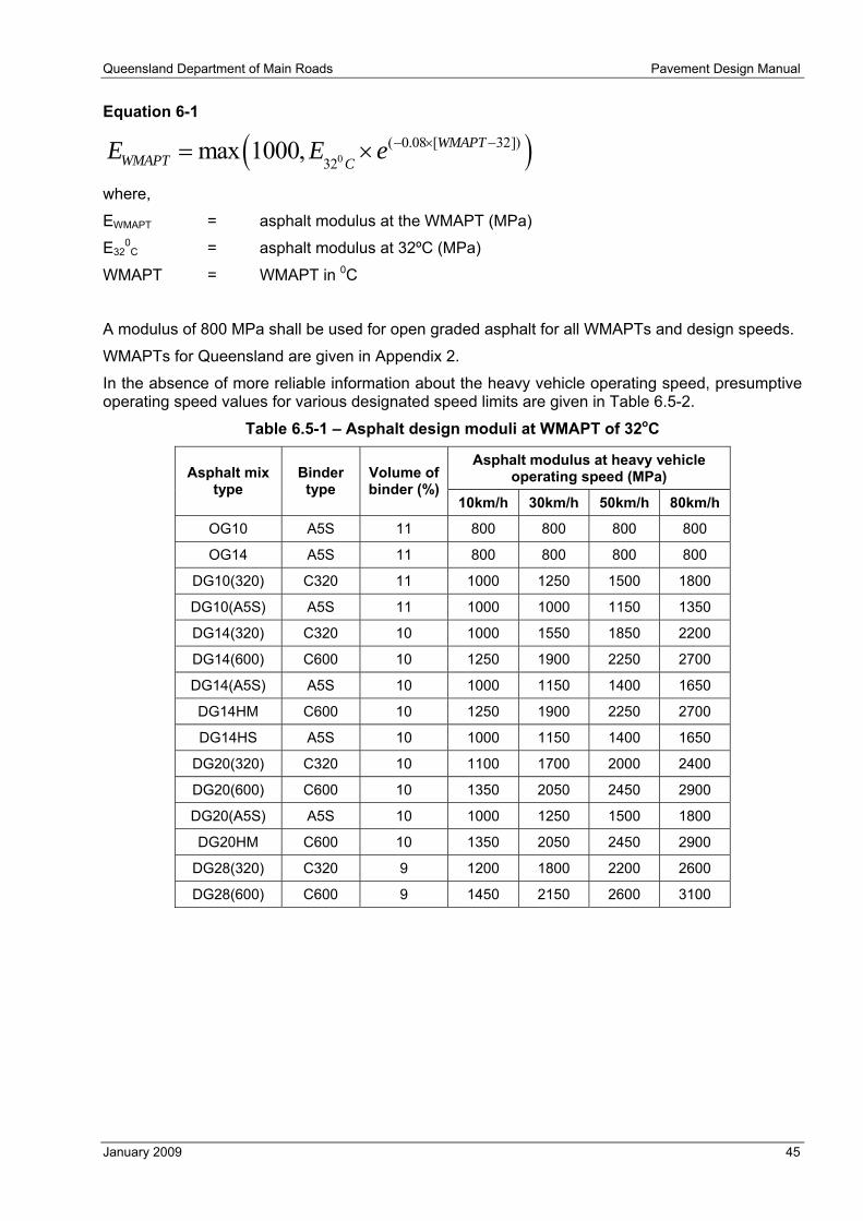
Queensland Department of Main Roads Pavement Design Manual
January 2009 45
Equation 6-1
( )0( 0.08 [ 32])
32max 1000, WMAPT
WMAPT CE E e − × −= ×
where,
EWMAPT = asphalt modulus at the WMAPT (MPa)
E320C = asphalt modulus at 32ºC (MPa)
WMAPT = WMAPT in 0C
A modulus of 800 MPa shall be used for open graded asphalt for all WMAPTs and design speeds.
WMAPTs for Queensland are given in Appendix 2.
In the absence of more reliable information about the heavy vehicle operating speed, presumptive operating speed values for various designated speed limits are given in Table 6.5-2.
Table 6.5-1 – Asphalt design moduli at WMAPT of 32oC
Asphalt modulus at heavy vehicle operating speed (MPa) Asphalt mix
type Binder
type Volume of binder (%)
10km/h 30km/h 50km/h 80km/h
OG10 A5S 11 800 800 800 800
OG14 A5S 11 800 800 800 800
DG10(320) C320 11 1000 1250 1500 1800
DG10(A5S) A5S 11 1000 1000 1150 1350
DG14(320) C320 10 1000 1550 1850 2200
DG14(600) C600 10 1250 1900 2250 2700
DG14(A5S) A5S 10 1000 1150 1400 1650
DG14HM C600 10 1250 1900 2250 2700
DG14HS A5S 10 1000 1150 1400 1650
DG20(320) C320 10 1100 1700 2000 2400
DG20(600) C600 10 1350 2050 2450 2900
DG20(A5S) A5S 10 1000 1250 1500 1800
DG20HM C600 10 1350 2050 2450 2900
DG28(320) C320 9 1200 1800 2200 2600
DG28(600) C600 9 1450 2150 2600 3100

Pavement Design Manual Queensland Department of Main Roads
46 January 2009
Table 6.5-2 – Presumptive heavy vehicle operating speeds
Presumptive heavy vehicle operating speed (km/h)Project location
Flat and up to 5% grade Over 5% grade Speed limit > 80 km/h 80 50
Speed limit 50–80 km/h 50 30
Roundabouts and approaches 30 10
Signalised intersections and approaches 10 10
Asphalt is made from materials with highly variable properties. The economics of pavement materials require the use of local aggregates, hence unique mix designs must be carried out to achieve desirable characteristics for mixes from a variety of sources.
6.5.3 Recycled asphalt Recycled asphalt shall not be used for the purposes of this manual.
6.5.4 Minimising water infiltration Virtually all asphalt is permeable to some extent, particularly when first laid. Permeability of the surfacing, if not tightly controlled, can lead to:
a) weakening of granular paving materials and subgrade, and subsequent rutting or shear failure
b) saturation of paving material, build-up of positive pore pressure and rapid failure
c) erosion in cemented layers
d) pumping of cemented materials and subgrade fines
e) stripping of binder in asphalt.
Each of these usually leads to dramatically reduced pavement performance. Therefore, the pavement design and construction should ensure that a surfacing with the lowest possible permeability is provided.
A polymer modified sprayed seal must be placed under all asphalt surface layers.
The construction process must be such that no intermediate asphalt layer is left exposed where rain is likely, or for longer than five working days where rain is not expected.
6.6 Concrete 6.6.1 Base concrete The 28-day design flexural strength of the concrete shall be 4.5 MPa. This is the value for design and is less than the specified value, as detailed in Austroads (2004). For steel fibre reinforced concrete, the 28-day design flexural strength shall be 5.5 MPa.

Queensland Department of Main Roads Pavement Design Manual
January 2009 47
7 DESIGN TRAFFIC
7.1 Average daily ESA in design lane in year of opening The average daily ESA in the design lane in the year of opening (ESA/day) is calculated using Equation 7-2, where the parameters are as defined in Part 2 of the Austroads guide.
Equation 7-1
/ ( * ) % /100 /ESA day AADT DF HV LDF ESA HV= × × ×
7.2 Selecting design period and assessment period The design periods and assessment periods given in Table 7.2-1 shall be used to determine the design traffic and carry out whole-of-life costing.
Table 7.2-1 – Minimum design period and assessment period
Average daily ESA in design lane in year of opening
Minimum design period (years) 1
Minimum assessment period (years) 1,2
≥ 1000 40 40
100 to < 1000 20 40
< 100 10 103 Notes 1) The design and/or assessment periods can be reduced to equal the life of the alignment where the life of
the alignment is less than the minimum requirements. 2) The assessment period shall be at least as long as the design period. 3) If required for the project.
For temporary pavements, the design period shall be selected based on the intended period of use, with a maximum design period of 2 years. In addition, for temporary pavements where the average daily ESA in the design lane in the year of opening is 1000 or more, the minimum design period shall be 6 months.
7.3 Identifying design lane Pavement designs are based on the cumulative number of heavy vehicles in the design lane. In most cases, the design lane is the most heavily trafficked lane (e.g. the left/slow lane on a typical multi-lane rural road). In some cases the design lane may not be the most heavily trafficked lane, such as when designing inside widening of a multi-lane carriageway.
7.4 Initial daily heavy vehicles in the design lane The heavy vehicle traffic volume in the year of opening may be determined by multiplying traffic volumes from a previous year by a growth factor (g) as shown Equation 7-2.
Equation 7-2
xrg )01.01( ×+=
where,
g = growth factor

Pavement Design Manual Queensland Department of Main Roads
48 January 2009
r = heavy vehicle growth rate per annum (%)
x = time period (years) between previous year traffic volumes and year of opening
7.5 Growth rate and cumulative traffic volumes In accordance with recent growth and the predicted doubling of the road freight task from 2000 to 2020 (DOTARS, 2002), all motorways (including ramps), highways and arterial roads shall be designed with a minimum heavy vehicle growth rate of 4% per annum, unless detailed traffic modelling is undertaken which specifically considers the future freight task for the pavement being designed.
7.6 Project specific traffic load distribution Whenever possible, designers should use project-specific weigh-in-motion data rather than presumptive values to determine relevant design traffic parameters.
7.7 Reduced design standard for sealed unbound granular pavements with average daily ESA < 100 in design lane in year of opening
This section is only to be used for sealed unbound granular pavements that satisfy the following conditions:
a) average daily ESA in design lane in year of opening is < 100
b) where there are justifiable reasons for allowing a higher level of performance risk
c) where allowance is made in the whole-of-life costing for additional maintenance treatments.
This procedure uses only roughness as an indicator of the effect of the reduced standard. It does not include other elements such as rut depth, volume change, or durability, for example. These must be independently addressed and assessed.
The empirical design procedure for granular pavements with thin bituminous surfacings (Section 8.3) is based on the premise that pavement roughness at the end of the design period (the terminal roughness) will be approximately 150 NAASRA counts/km, assuming that the initial roughness is approximately 50 NAASRA counts/km.
Where a reduced standard is adopted, the design traffic (DESA) can be modified so that the pavement design allows for alternative variations in the initial pavement condition and choice of terminal pavement condition. This is done by using the ratio of terminal roughness to initial roughness. A suitable initial roughness value can be estimated from measurements of recently constructed pavements under similar conditions.
The modified design traffic is determined from Figure 7.7-1 using the unmodified design traffic and the desired ratio of terminal to initial roughness. For example, if the unmodified design traffic is 1 x 10⁶ ESA and the designer seeks a pavement design that will result in terminal roughness being four times the initial roughness, the value of the modified design traffic is 4 x 10⁵ ESA.
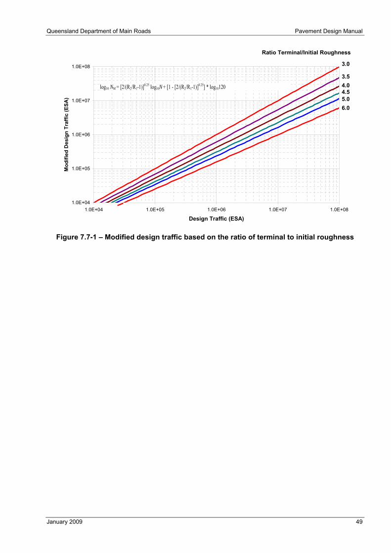
Queensland Department of Main Roads Pavement Design Manual
January 2009 49
1.0E+04
1.0E+05
1.0E+06
1.0E+07
1.0E+08
1.0E+04 1.0E+05 1.0E+06 1.0E+07 1.0E+08
Design Traffic (ESA)
Mod
ified
Des
ign
Traf
fic (E
SA)
Ratio Terminal/Initial Roughness
5.04.54.03.5
3.0
6.0
log10 NM = [2/(R2/R1-1)]0.25 log10N + [1 - [2/(R2/R1-1)]0.25] * log10120
Figure 7.7-1 – Modified design traffic based on the ratio of terminal to initial roughness

Pavement Design Manual Queensland Department of Main Roads
50 January 2009
8 DESIGN OF NEW FLEXIBLE PAVEMENTS
8.1 General The calculated layer thicknesses shall be rounded up to the nearest 5 mm.
To allow for variations in the constructed layer thicknesses within the construction tolerances, a construction tolerance shall be added to the pavement design thickness.
For unbound granular, modified granular and thin asphalt surfaced granular pavements, a thickness of 20 mm shall be added to the total unbound granular thickness determined as appropriate from Figure 8.4 of Part 2 of the Austroads guide or from mechanistic design.
For full depth asphalt, deep strength asphalt, flexible composite and AG(A) and ASt(A) pavements, 10 mm shall be added to the pavement layer that governs the overall allowable loading to account for layer thickness variations.
For ASt(B) temporary pavements, 20 mm shall be added to the design thickness of the stabilised base layer.
8.2 Mechanistic procedure Mechanistic design must be undertaken using the latest version of CIRCLY.
It is assumed that thin interlayer and surface treatments such as sprayed seals and geosynthetics are non-structural.
Generally mechanistic modelling is undertaken assuming full bonding between layers, characterised as a ‘rough’ interface in the CIRCLY program. However, when modelling pavements with more than two stabilised layers, only one of the interfaces between stabilised layers shall be modelled as fully bonded, and any other interfaces between stabilised layers shall be modelled as smooth interfaces.
Because of the risk of poor performance as a result of inadequate bonding between layers, the assumption of full bonding between layers in design of permanent pavements shall not be used where the average daily ESA in the design lane in the year of opening is ≥ 1000.
8.2.1 Selecting a trial pavement Refer to pavement types and standards discussed in Section 2.3 of this manual and Section 2.2.2 of Part 2 of the Austroads guide.
8.2.2 Consideration of post-cracking phase in cemented materials The post-cracking phase may be included for deep strength asphalt, flexible composite and ASt(A) pavements where the average daily ESA in the design lane in the year of opening is < 1000. For higher traffic levels the post-cracking phase is not to be included.
8.3 Empirical design of unbound granular pavements with thin bituminous surfacing
The total thickness of a granular pavement is made up of a base and may include any number of subbase courses.
The required minimum base thickness is obtained from Figure 8.4 in Part 2 of the Austroads guide, except for the SG(A) pavement type (refer to Table 2.3-4) for which the base shall comprise two 100 mm thick granular B1 layers.
If a thin (< 40 mm thick) dense graded asphalt surfacing is provided, the thickness of the surfacing may be deducted from the required total granular thickness. However, the minimum base thickness requirements still apply.

Queensland Department of Main Roads Pavement Design Manual
January 2009 51
The thickness of any base, sub-base or lower sub-base layer shall not be less than 100 mm as construction quality may be adversely affected for lesser thicknesses.
8.4 Modified granular pavements Thickness design of modified granular pavements is to be based on either Figure 8.4 in Part 2 of the Austroads guide, or mechanistic design using the same modelling procedures as for unbound granular pavements.
8.5 Example design charts for mechanistic design The example design charts in Part 2 of the Austroads guide may be used to establish a trial thickness for a given subgrade design CBR and design traffic for commencement of the normal iterative mechanistic design procedure. These are based on a number of design assumptions so their relevance to a particular project may be limited.
Pavement Design Manual Queensland Department of Main Roads
52 January 2009
9 DESIGN OF NEW RIGID PAVEMENTS
9.1 General The calculated layer thicknesses shall be rounded up to the nearest 5 mm.
To allow for variations in the constructed layer thicknesses within the construction tolerances, a construction tolerance of 10 mm shall be added to the design base thickness.
The thicknesses given in Table 9.7 of Part 2 of the Austroads guide are minimum design thicknesses, and therefore a construction tolerance of 10 mm must also be added to those thicknesses.
For detailed design of slab layouts and joints, the designer should refer to the following publications, and also seek advice from Pavements and Materials Branch to ascertain the latest requirements:
a) RTA 1992, Concrete Pavement Manual: Design and Construction, 2nd edn, Roads and Traffic Authority, Sydney.
b) RTA 2004, TP-GDL-012: Concrete Roundabout Pavements: A Guide to their Design and Construction, Roads and Traffic Authority, Sydney.
c) RTA, Rigid Pavements: Standard Details for Design, Roads and Traffic Authority, Sydney.
9.2 Pavement types Permitted rigid pavement types are shown in Table 2.3-2.
The subbase shall be lean mix concrete with a minimum thickness of 150 mm.
To reduce excavation requirements in tunnels, a minimum 150 mm of no-fines concrete plus a minimum 25 mm of dense graded asphalt can be used instead of a lean mix concrete subbase and a separate drainage layer. The thickness of no-fines concrete must be sufficient to allow complete drainage of any moisture present. Use of no-fines concrete for drainage is not suitable in some ground conditions where blockage of drainage paths in the no-fines concrete may occur. This can occur where material transported by ground water (dissolved or undissolved) deposits itself within the no-fines concrete, or a chemical reaction between the ground water and the no-fines concrete results in the formation of a precipitate.
Where no-fines concrete subbase is used for base thickness design purposes the total thickness of the no-fines concrete and asphalt is to be modelled as a 150 mm lean mix concrete layer.
A specification for no-fines concrete is available from Pavements & Materials Branch.
Where an open-graded asphalt surface is provided over continuously reinforced concrete pavement (CRCP), a minimum thickness of 40 mm of DG14HS dense graded asphalt must be provided under the open-graded asphalt to protect the concrete base from milling during future resurfacing.
The minimum design base thickness for JRCP, CRCP and SFRC busway pavements is 230 mm (240 mm including 10 mm tolerance).
9.3 Concrete channels A separately placed channel made of structural grade concrete may provide some edge support to the pavement, but less than a full concrete shoulder. Therefore, a separately placed channel does not warrant a reduction in pavement thickness. In this case, a ‘no shoulder’ design condition is to be adopted.

Queensland Department of Main Roads Pavement Design Manual
January 2009 53
9.4 Example design charts for rigid pavements The example design charts in Part 2 of the Austroads guide may be used to establish a trial thickness for a given subgrade design CBR and design traffic for commencement of the normal iterative rigid pavement design procedure. These are based on a number of design assumptions so their relevance to a particular project may be limited.
Pavement Design Manual Queensland Department of Main Roads
54 January 2009
10 COMPARISON OF DESIGNS
10.1 General When comparing various alternative pavement types and configurations, cost is a prime consideration. For most lightly trafficked roads, a granular pavement with a sprayed seal will usually prove to be the most cost-effective pavement. However, for medium to heavy traffic loads, particularly over weak subgrades, other pavement types may be more cost effective. To determine the most cost-effective pavement, a whole-of-life cost comparison must be made.
Technical and financial considerations influence the types of pavement selected for consideration on a project. An analysis of these factors is needed prior to undertaking an economic evaluation. Financial considerations may limit the acceptable pavement options.
The various features of alternative designs need to be explored and agreed upon at this stage. These include:
● purpose, scope and objective of the design comparison
● outputs of the analysis
● technical project constraints on pavement types to be considered, including the operating environment such as traffic predictions and subgrade conditions
● maximum pavement capital cost limitations, if any
● feasible pavement alternatives to be analysed
● maintenance scenario(s)
● assessment period
● pavement design life
● other underlying assumptions
● an estimate of the resources required to complete the analysis.
In order to determine the acceptability of the proposed scope and parameters of the analysis, and to minimise rework, these should be recorded, reviewed and accepted by the decision-maker who is to consider the study results. If some of the above cannot be determined at this stage, an outline of how these issues will be treated, whether by assumption or further investigation in the study, should be documented. The parameters, once agreed, may be varied later during the study by agreement with the decision-maker as further information becomes available.
For heavy-duty pavements, comparison of alternative pavement types and configurations shall be undertaken in accordance with A Guide to the Whole-of-Life Costing of Heavy Duty Pavements (QDMR 1998).
10.1.1 Assessment period The assessment period for road pavements, usually expressed in calendar years, starts from the initial trafficking of the original structure and has a duration that is the least of either:
a) the period for which the models for pavement design traffic determination and/or pavement design are considered accurate (usually accepted as 40 years)
b) the period for which the use of the pavement and/or the road alignment can be assured.
Pavements consist of many elements, each of which has a different design life. Some of these design lives are short and less than the expected service life of the overall pavement. To maintain the functional requirements of the pavement, planned interventions that extend the life of particular elements will usually be required. These interventions may include, but are not limited to:
● enrichments

Queensland Department of Main Roads Pavement Design Manual
January 2009 55
● reseals
● overlays
● removal and replacement of the surface layer and underlying seal
● retexturing
● maintenance.
There can also be interventions after the original design period to further extend the life of the pavement if it is still required. These are usually categorised as rehabilitation (refer to MR Pavement Rehabilitation Manual for further details).
In determining the design lives of individual elements, the design charts or mechanistic design are only one indicator of possible life. Many other considerations, including other loads, such as horizontal shear, could significantly influence the design life.
Pavement alternatives within the assessment period provide different options in respect of:
● risk
● cost (initial cost, total whole-of-life cost, intervention costs)
● interventions and consequent user disruption.
The alternative that satisfies the owner’s particular needs (including affordability) at the time is the appropriate design.
The assessment period must not be selected on the basis of available budgets, present and/or future. Budget influences, along with risk and intervention costs, are accommodated in the choice of pavement alternatives, assisted by reference to the dominant criteria, as indicated below.
Design period or design life as used in this supplement is not the life of the whole pavement, but the service life of a particular pavement element, for example: the fatigue life of a concrete or asphalt layer, the terminal rut condition, the life before excessive oxidation of a surface bituminous layer.
10.1.2 Design inclusions A pavement design must include not only the original structure but also all those interventions in the assessment period necessary for the pavement to maintain its function to the end of the assessment period. These include:
a) initial structure
b) interventions, including, but not limited to
i) essential maintenance tasks
ii) staged construction activities (such as incremental overlays) if these have been part of the design
iii) treatment of surface layers (such as reseal, recycle, remove and replace) on a regular basis where surface layers cannot be designed to last the full assessment period.
A pavement design must include all activities considered necessary for the design to last for the specified assessment period, and not just those activities required for the initial structure.
10.1.3 Determining the optimal solution The optimal pavement design solution is that which best satisfies the design requirements for the specified inputs at minimum cost for the whole life of the pavement, and allows for the following constraints:
a) design considerations that cannot readily be quantified and taken into account by the design procedures in this manual

Pavement Design Manual Queensland Department of Main Roads
56 January 2009
b) the needs of road users and the community
c) road safety
d) future maintenance
e) availability of plant and materials
f) drainage
g) environmental considerations (e.g. noise).
The cost criterion to be applied for comparison of alternatives is minimum whole-of-life cost, which allows for discounted future maintenance and rehabilitation costs. However, certain design constraints which are not easily quantified must be applied to allow for factors that influence maintenance, safety and user costs. These constraints may override cost considerations.
10.1.4 Selection constraints The following examples illustrate practical constraints on the choice of design options:
● Although asphalt surfaces are more costly than sprayed surface treatments, they are provided on heavily trafficked roads because of the costs of traffic disruption and the dangers to traffic and workers associated with maintaining a sprayed seal.
● Certain combinations of pavement and shoulder materials and their configuration in the pavement may be required to promote pavement drainage.
● Where the pavement is likely to be exposed to soaked conditions for extended periods, cement or bituminous bound material will be required to protect the structural integrity and service standard of the pavement, despite possible additional costs.
● When comparing the cost of structurally equivalent alternatives, consideration must be given to non-productive costs associated with establishment, overheads, provision for traffic and wet weather. These may be different for each alternative.
● The type and configuration of the pavement selected may impact more than just the pavement and direct pavement costs. For example the selection of a dense graded asphalt overlay may necessitate the construction of noise mounds/barriers adding to total project cost. Ancillary or indirect impacts must be considered.

Queensland Department of Main Roads Pavement Design Manual
January 2009 57
11 TYPICAL CROSS SECTIONS Typical cross sections, pavement structures and pavement edge details for various pavement configurations are shown in the following figures.
The cross sections, including shoulder widths and verge requirements, are the minimum requirements for structural reasons and are not those that may be required for other reasons such as trafficability, sight distance, safe standing, guardrails, signs and so on. Other relevant manuals, guides and / or technical notes are to be consulted for these issues. Actual details to be adopted must also comply with the Main Roads Road Planning and Design Manual.
11.1 Typical cross sections
Subgrade Treatments- cover over reactive subgrade- capping layer- drainage layer
Surface
Workingplatform
3.0 trafficked lanemin. 1.0 (median side)
min. 2.0 (other)
CL
trafficked lane
Note: 1. These are minimums relating to structural requirements.
SealBinder
Base
(1)(1)
Figure 11.1-1 – HILI asphalt
(full depth asphalt, flexible composite and deep strength asphalt)
3.0 3.5min. 1.0 (median side)
min 2.0 (other)
CL
3.5
Drain
0.6
Surface (asphalt)[continuously reinforced only]
BaseLean mix subbase
Working platform
0.6
Subgrade Treatments- cover over reactive subgrade- capping layer- drainage layer
Notes: 1. These are minimums relating to structural requirements.2. Minimum width of base for designs with shoulders.
(2)
(1)
Figure 11.1-2 – HILI concrete
(unreinforced, jointed reinforced and continuously reinforced)
min. 2.0min. 2.0
min. 1.0 (median)
CL
trafficked lane
Full width sealPavement structure
Working platform (if specified)min 200 mm frombottom of workingplatform
(1)(1)
trafficked lane
Subgrade Treatments- cover over reactive subgrade- capping layer- drainage layer
Note: 1. These are minimums relating to structural requirements.
Figure 11.1-3 – Unbound granular and cement modified base
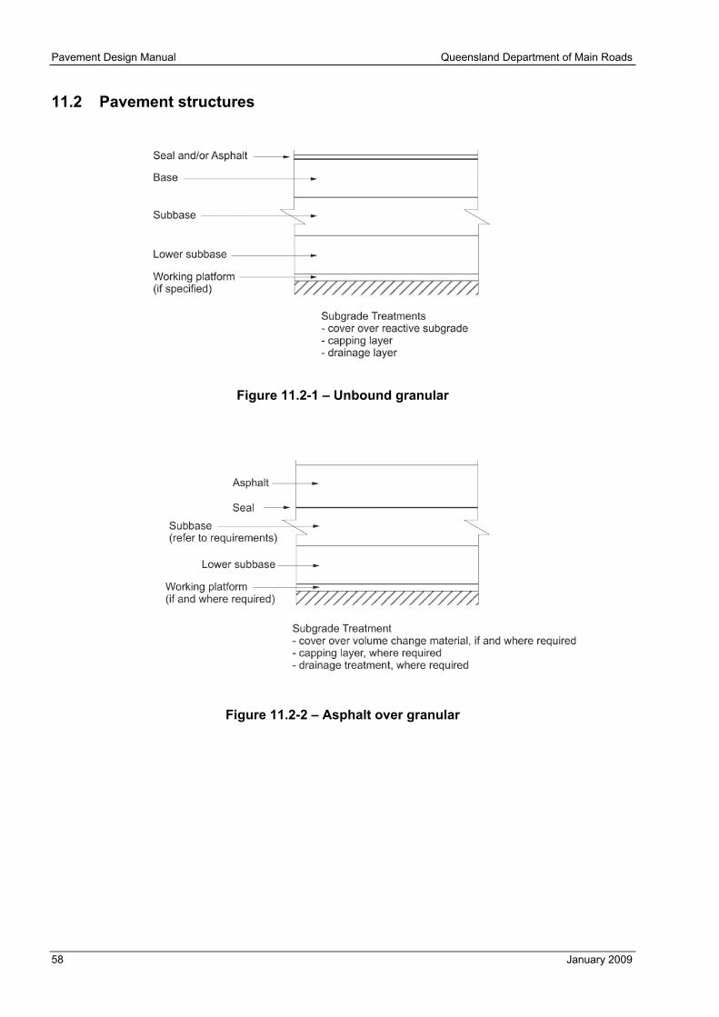
Pavement Design Manual Queensland Department of Main Roads
58 January 2009
11.2 Pavement structures
Figure 11.2-1 – Unbound granular
Figure 11.2-2 – Asphalt over granular
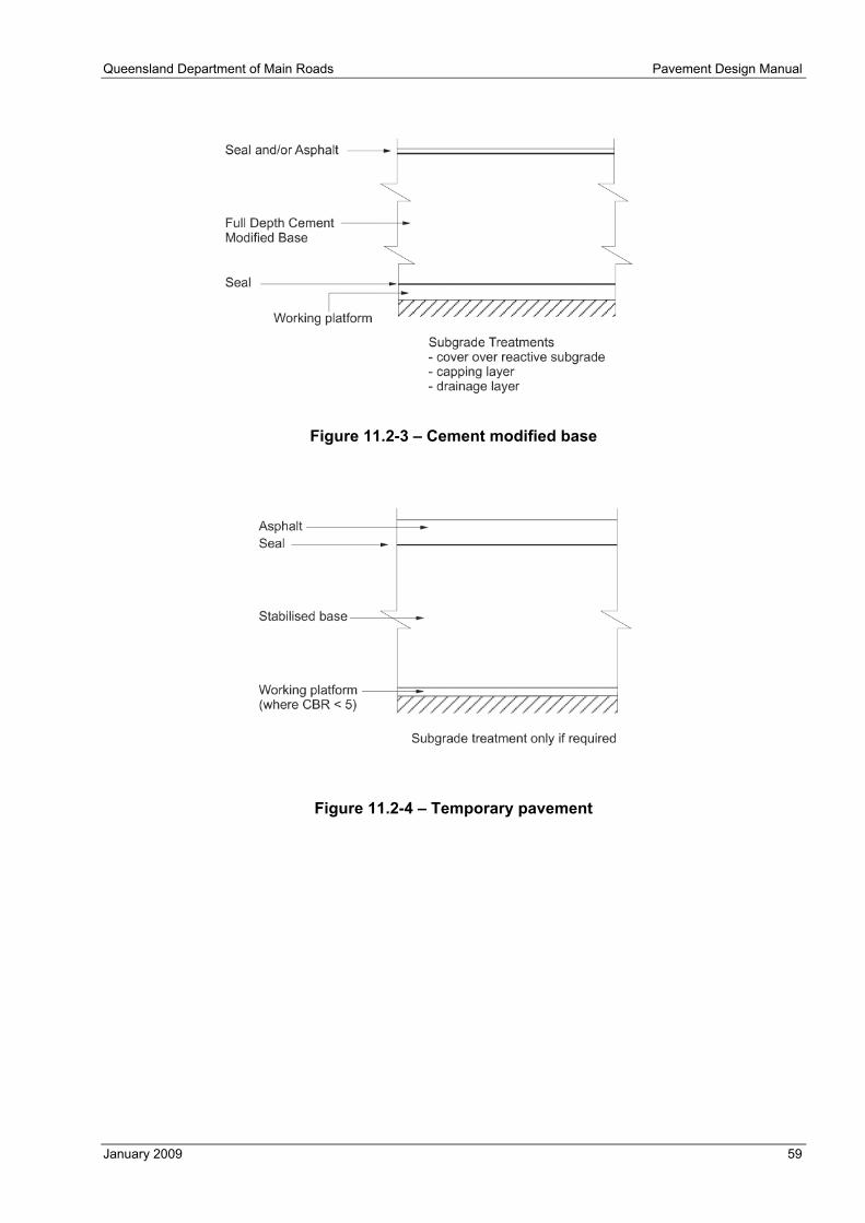
Queensland Department of Main Roads Pavement Design Manual
January 2009 59
Figure 11.2-3 – Cement modified base
Figure 11.2-4 – Temporary pavement

Pavement Design Manual Queensland Department of Main Roads
60 January 2009
11.3 Pavement edge details
Figure 11.3-1 – HILI pavement in cutting
Figure 11.3-2 – High side of one-way crossfall (all pavements)
Figure 11.3-3 – Cutting with open table drain

Queensland Department of Main Roads Pavement Design Manual
January 2009 61
12 REFERENCES
Austroads 2003, AP-G63/03: Guide to the Selection of Road Surfacings, 2nd edn, Austroads, Sydney.
Austroads 2004a, AP-G76/04: ‘Sprayed Sealing Guide’, Austroads Pavement Technology Series, Austroads, Sydney.
Austroads 2004b, AP-T33/04: Technical Basis of the Austroads Pavement Design Guide, Austroads, Sydney.
Austroads 2008, ‘Part 2: Pavement Structural Design’, Guide to Pavement Technology, Austroads, Sydney.
DOTARS 2002, AusLink: Towards the National Land Transport Plan, Green paper, Department of Transport and Regional Services, Canberra.
Powell, W.D., Potter, J.F., Mayhew, H.C. 1984, Laboratory Report 1132: The Structural Design of Bituminous Roads, Transport and Road Research Laboratory, Crowthorne, Berks, UK.
QDMR 1998, A Guide to the Whole-of-Life Costing of Heavy Duty Pavements. Queensland Department of Main Roads, Pavements, Materials and Geotechnical Division, Brisbane.
RTA 1992, Concrete Pavement Manual: Design and Construction, 2nd edn, Roads and Traffic Authority, Sydney.
RTA 2004, TP-GDL-012: Concrete Roundabout Pavements: A Guide to their Design and Construction, Roads and Traffic Authority, Sydney.
RTA, Rigid Pavements: Standard Details for Design, Roads and Traffic Authority, Sydney.
Standards Australia 1997, AS 1289.4.2.1: ‘Method 4.2.1: Soil chemical tests—Determination of the sulfate content of a natural soil and the sulfate content of the groundwater—Normal method’, Methods of testing soil for engineering purposes, Standards Australia, Sydney.

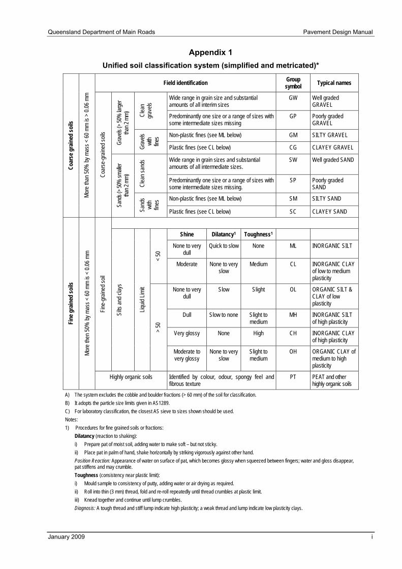
Queensland Department of Main Roads Pavement Design Manual
January 2009 i
Appendix 1 Unified soil classification system (simplified and metricated)*
Field identification Group symbol Typical names
Wide range in grain size and substantial amounts of all interim sizes
GW Well graded GRAVEL
Clea
n gr
avels
Predominantly one size or a range of sizes with some intermediate sizes missing
GP Poorly graded GRAVEL
Non-plastic fines (see ML below) GM SILTY GRAVEL
Grav
els (>
50%
large
r tha
n 2 m
m)
Grav
els
with
fines
Plastic fines (see CL below) CG CLAYEY GRAVEL
Wide range in grain sizes and substantial amounts of all intermediate sizes.
SW Well graded SAND
Clea
n san
ds
Predominantly one size or a range of sizes with some intermediate sizes missing.
SP Poorly graded SAND
Non-plastic fines (see ML below) SM SILTY SAND
Coar
se g
rain
ed so
ils
More
than
50%
by m
ass <
60 m
m is
> 0.0
6 mm
Coar
se-g
raine
d soil
s
Sand
s (> 5
0% sm
aller
than 2
mm)
Sand
s wi
th fin
es
Plastic fines (see CL below) SC CLAYEY SAND
Shine Dilatancy1 Toughness1
None to very dull
Quick to slow None ML INORGANIC SILT
< 50
Moderate None to very slow
Medium CL INORGANIC CLAY of low to medium plasticity
None to very dull
Slow Slight OL ORGANIC SILT & CLAY of low plasticity
Dull Slow to none Slight to medium
MH INORGANIC SILT of high plasticity
Very glossy None High CH INORGANIC CLAY of high plasticity
Fine-
grain
ed so
il
Silts
and c
lays
Liquid
Limi
t
> 50
Moderate to very glossy
None to very slow
Slight to medium
OH ORGANIC CLAY of medium to high plasticity
Fine
gra
ined
soils
More
then
50%
by m
ass <
60 m
m is
< 0.0
6 mm
Highly organic soils Identified by colour, odour, spongy feel and fibrous texture
PT PEAT and other highly organic soils
A) The system excludes the cobble and boulder fractions (> 60 mm) of the soil for classification. B) It adopts the particle size limits given in AS1289. C) For laboratory classification, the closest AS sieve to sizes shown should be used. Notes: 1) Procedures for fine grained soils or fractions: Dilatancy (reaction to shaking):
i) Prepare pat of moist soil, adding water to make soft – but not sticky. ii) Place pat in palm of hand, shake horizontally by striking vigorously against other hand.
Position Reaction: Appearance of water on surface of pat, which becomes glossy when squeezed between fingers; water and gloss disappear, pat stiffens and may crumble. Toughness (consistency near plastic limit):
i) Mould sample to consistency of putty, adding water or air drying as required. ii) Roll into thin (3 mm) thread, fold and re-roll repeatedly until thread crumbles at plastic limit. iii) Knead together and continue until lump crumbles.
Diagnosis: A tough thread and stiff lump indicate high plasticity; a weak thread and lump indicate low plasticity clays.
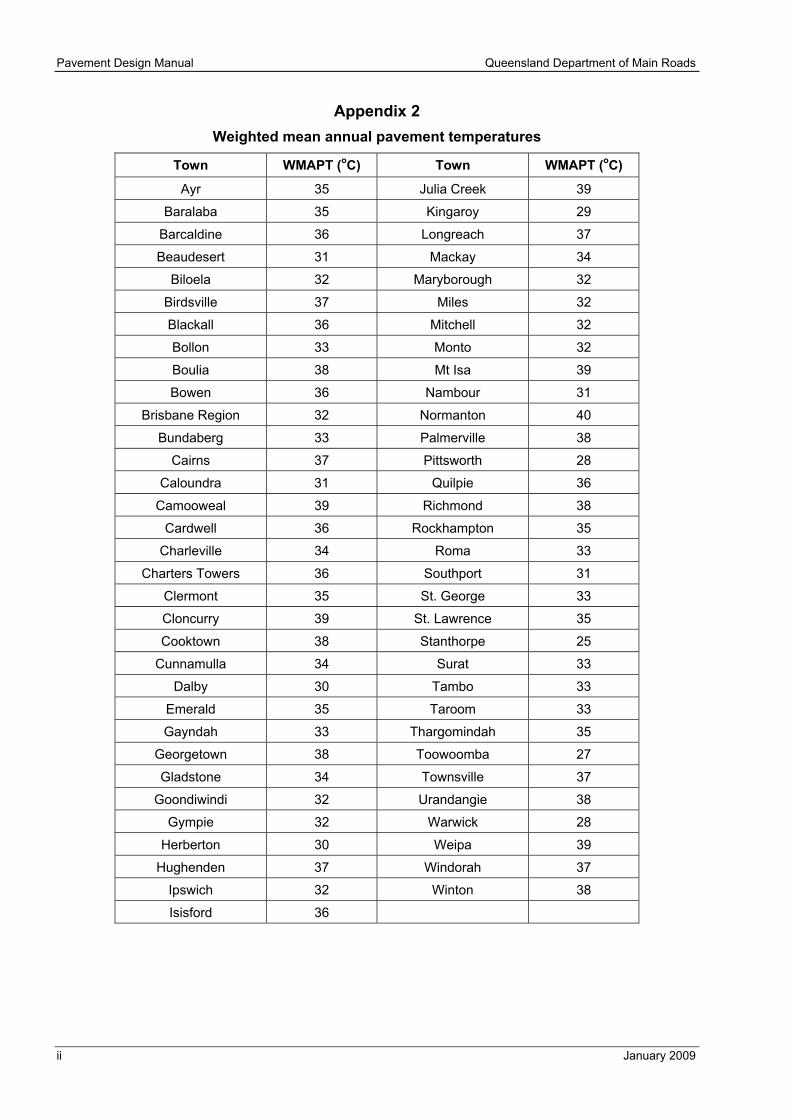
Pavement Design Manual Queensland Department of Main Roads
ii January 2009
Appendix 2 Weighted mean annual pavement temperatures
Town WMAPT (oC) Town WMAPT (oC)
Ayr 35 Julia Creek 39
Baralaba 35 Kingaroy 29
Barcaldine 36 Longreach 37
Beaudesert 31 Mackay 34
Biloela 32 Maryborough 32
Birdsville 37 Miles 32
Blackall 36 Mitchell 32
Bollon 33 Monto 32
Boulia 38 Mt Isa 39
Bowen 36 Nambour 31
Brisbane Region 32 Normanton 40
Bundaberg 33 Palmerville 38
Cairns 37 Pittsworth 28
Caloundra 31 Quilpie 36
Camooweal 39 Richmond 38
Cardwell 36 Rockhampton 35
Charleville 34 Roma 33
Charters Towers 36 Southport 31
Clermont 35 St. George 33
Cloncurry 39 St. Lawrence 35
Cooktown 38 Stanthorpe 25
Cunnamulla 34 Surat 33
Dalby 30 Tambo 33
Emerald 35 Taroom 33
Gayndah 33 Thargomindah 35
Georgetown 38 Toowoomba 27
Gladstone 34 Townsville 37
Goondiwindi 32 Urandangie 38
Gympie 32 Warwick 28
Herberton 30 Weipa 39
Hughenden 37 Windorah 37
Ipswich 32 Winton 38
Isisford 36