patient manual - vq orthocare...patient manual orthostim4 rehabilitative electrotherapy from vq...
TRANSCRIPT

Patient ManualOrthoStim4 Rehabilitative Electrotherapy
from VQ OrthoCare18011 Mitchell South, Irvine, CA 92614
Call 800.266.6969 Fax 800.821.8012www.vqorthocare.com
© 2010 VisionQuest Industries, Inc.VQO021578REVA

VQ OrthoCare is not liable for any misuse or misunderstanding of theOrthoStim4 product or operating manual. Please call your local representative if any additional assistance is required regarding this product and its operating instructions.
This patient manual is proprietary and confi dential. No part of this document may be reproduced or transmitted in any form or by any means, electronic or mechanical, including photocopy, recording or information storage and retrieval system, without permission in writing from VQ OrthoCare.
VQ OrthoCare warrants the OrthoStim4 to be free from electrical circuit defects in workmanship and materials for a period of three (3) years upon delivery to the customer. The case, cradle and belt clip are warranted to be free from defects in workmanship and materials for one (1) year upon delivery to the customer. VQ OrthoCare will repair or replace, at its facilities, any OrthoStim4 unit found to have become defective within the warranty period.
This warranty does not apply to accessories; specifi cally lead wires, electrodes, batteries, tapes, gel, carrying case and AC Adapter, nor does it apply to OrthoStim4 units that have been damaged due to misuse, or repaired or altered by parties other than VQ OrthoCare at its facilities.
This warranty is in lieu of any other warranties expressed or implied. No person or entity is authorized to bind VQ OrthoCare to any representa-tion of warranty other than those specifi cally set forth herein.
Warranty
41

Letter to the Patient ......................................................................2
System Components ...................................................................3
Precautions and Prescription Information ..............................4
Controls and Features .................................................................6
Accessories ....................................................................................8
Starting Your Treatment Sessions ...........................................10
Normal Running Screens ..........................................................13
After Completing Your Treatment Sessions ..........................17
Electrode Use and Care.............................................................18
Cradle/Modem ............................................................................19
Care and Maintenance ..............................................................22
Technical Data and Specifi cations .........................................26
Waveform Diagrams ..................................................................30
Troubleshooting .........................................................................37
Notes .............................................................................................39
Warranty .......................................................................................41
Table of Contents

2
Letter to the PatientYour physician has selected the OrthoStim4 – a portable multi-modality device that provides Interferential, Neuromuscular, Pulsed Direct Current and High-Volt Pulsed Current Stimulation – as the most appropriate treat-ment for your needs.
The OrthoStim4 electrical stimulator generates small pulses of current that are delivered through lead wires to stimulating electrodes* placed on your skin. These pulses pass through the skin and activate underlying nerves. The OrthoStim4 activates sensory nerves at lower levels of stimulation, producing a tingling sensation. Motor nerves are activated at higher levels of stimulation, resulting in muscle contractions.
The OrthoStim4 system includes a cradle equipped with a modem that enables your doctor or therapist and our technicians to conveniently admin-ister setting changes to the device and keep your prescription information up to date. As a patient, you may also take advantage of this technology to make modifi cations to your settings, and to assist all of your healthcare partners in providing the most personalized service possible.
In order to gain maximum benefi t from your OrthoStim4 treatment, it is important that you follow the therapy regimen prescribed by your physi-cian or therapist. He or she is familiar with your specifi c requirements and the technical specifi cations of the OrthoStim4, and will instruct you on the proper mode of operation and correct degree of stimulation for your individual treatment.
Please read the following sections carefully before using the OrthoStim4. • Precautions and Prescription Information • Controls and Features • Starting Your Treatment Sessions • Care and Maintenance
NOTE: The OrthoStim4 is not a substitute for full medical evaluation and treatment. Always consult your physician or therapist if you have specifi c questions or problems regarding the use of your OrthoStim4. The Ortho-Stim4 should not be given to or used by any individual other than the person for whom it is prescribed.
* For use only with stimulating electrodes, commonly referred to as “electrodes” throughout this manual

3
System ComponentsThe OrthoStim4 multi-modality stimulation system is operated with:
(1) OrthoStim4 electrotherapy device (1) package of non-sterile, reusable electrodes (1) lead wire (2) Power Packs
The OrthoStim4 system also includes: (1) carrying case with removable shoulder pouch (1) Patient Manual (this booklet) (2) additional packages of non-sterile, reusable electrodes
(depending on your doctor’s protocol) (8) adhesive remover towelettes (4) additional Power Packs (1) AC Adapter (1) cradle with modem (1) telephone cord with splitter
A
A
B
B
C
C
D
D
E
E
F
F
G
G
H
H
I
4
Precautions and Prescription Information
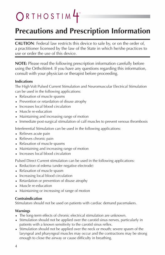
CAUTION: Federal law restricts this device to sale by, or on the order of, a practitioner licensed by the law of the State in which he/she practices to use or order the use of this device.
NOTE: Please read the following prescription information carefully before using the OrthoStim4. If you have any questions regarding this information, consult with your physician or therapist before proceeding.
IndicationsThe High Volt Pulsed Current Stimulation and Neuromuscular Electrical Stimulation can be used in the following applications:• Relaxation of muscle spasms • Prevention or retardation of disuse atrophy • Increases local blood circulation • Muscle re-education • Maintaining and increasing range of motion • Immediate post-surgical stimulation of calf muscles to prevent venous thrombosis
Interferential Stimulation can be used in the following applications:• Relieves acute pain • Relieves chronic pain• Relaxation of muscle spasms • Maintaining and increasing range of motion • Increases local blood circulation
Pulsed Direct Current stimulation can be used in the following applications:• Reduction of edema (under negative electrode) • Relaxation of muscle spasm • Increasing local blood circulation • Retardation or prevention of disuse atrophy • Muscle re-education• Maintaining or increasing of range of motion
ContraindicationStimulators should not be used on patients with cardiac demand pacemakers.
Warnings• The long-term effects of chronic electrical stimulation are unknown.• Stimulation should not be applied over the carotid sinus nerves, particularly in
patients with a known sensitivity to the carotid sinus refl ex.• Stimulation should not be applied over the neck or mouth; severe spasm of the
laryngeal and pharyngeal muscles may occur and the contractions may be strong enough to close the airway or cause diffi culty in breathing.

5
• Electrodes should not be placed on the chest in such a confi guration that would allow electrical current delivered by the device to fl ow through the chest because it may cause a cardiac arrhythmia.
• Stimulation should not be applied transcerebrally.• Stimulation should not be applied over swollen, infected, or infl amed areas or skin
eruptions, e.g. phlebitis, thrombophlebitis, varicose veins, etc.• Stimulation should not be applie d over, or in proximity to, cancerous lesions.• Due to the potential for causing skin burns, this device should only be used with electrodes which limit the current density to 0.25W/cm2
• Stimulation should not be applied transthoracically in that the introduction of electrical current may cause cardiac arrhythmias. Precautions• Safety of stimulators for use during pregnancy has not been established.• Caution should be used for patients with suspected or diagnosed heart problems.• Caution should be used for patients with suspected or diagnosed epilepsy.• Caution should be used in the presence of the following: - When there is a tendency to hemorrhage following acute trauma or fracture - Following recent surgical procedures when muscle contraction may disrupt
the healing process - Over the menstruating or pregnant uterus - Over areas of the skin which lack normal sensation
• Some patients may experience skin irritation or hypersensitivity due to electrical stimulation or electrical conductive medium. The irritation can usually be reduced by using an alternative conductive medium or alternate electrode placement.
• Electrode placement and stimulation setting should be based on the guidance of the prescribing practitioner.
• Keep out of the reach of children.• Use only with the lead wires and electrodes recommended for use by
the manufacturer.• Portable stimulators should not be used while driving, operating machinery, or
during any activity in which involuntary muscle contractions may put the user at undue risk of injury.
• When the amplitude in the IF mode exceeds 40mA, electrical noise from the device could interfere with other equipment operating in the nearby area.
• Do not trim electrodes as cut edges may affect even distribution of stimulation.• Do not immerse electrodes in water.
Adverse Reactions Skin irritation and burns beneath the electrodes have occasionally been reported with the use of electrical stimulators. If you experience any symptoms of skin irritation or any unusual reactions while using the OrthoStim4, discontinue use immediately and contact VQ OrthoCare’s Patient Care Department at 800.452.7993 or consult your physician.
6
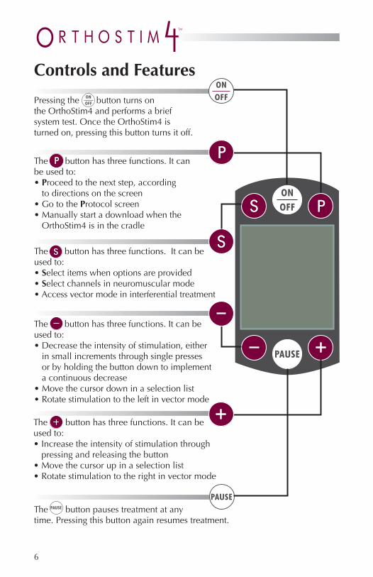
Controls and Features
Pressing the button turns on the OrthoStim4 and performs a brief system test. Once the OrthoStim4 is turned on, pressing this button turns it off.
The button pauses treatment at anytime. Pressing this button again resumes treatment.
The (–) button has three functions. It can be used to:• Decrease the intensity of stimulation, either
in small increments through single presses or by holding the button down to implement a continuous decrease
• Move the cursor down in a selection list• Rotate stimulation to the left in vector mode
The (+) button has three functions. It can be used to:• Increase the intensity of stimulation through
pressing and releasing the button• Move the cursor up in a selection list• Rotate stimulation to the right in vector mode
The (S) button has three functions. It can be used to:• Select items when options are provided• Select channels in neuromuscular mode• Access vector mode in interferential treatment
The (P) button has three functions. It can be used to:• Proceed to the next step, according
to directions on the screen• Go to the Protocol screen• Manually start a download when the
OrthoStim4 is in the cradle

7
Battery Indicator A battery symbol in the upper left corner ofthe screen will display the battery status. When the battery is fully charged, the symbol displays as black. When the battery power is low, the symbol displays as white, and starts to fl ash and the device will beep once a minute. Replace the alkaline Power Packs as soon as possible. When battery power is suf-fi ciently depleted, the device will shut off automatically.
AC Adapter Indicator When an AC Adapter is plugged into the OrthoStim4, a plug symbol appears next to the battery indicator. The AC Adapter bypasses the Power Packs and supplies the power.
Full Replace

8
AccessoriesLead Wire The lead wire connects the OrthoStim4 to the electrodes. When plugging the lead wireinto the OrthoStim4, make sure it is pushed fi rmly into the socket, with the strain relief pointing toward the bottom of the OrthoStim4 (as shown). To remove the wire, grip the connector close to the socket and pull straight out.
Power Supply The OrthoStim4 can be operated with two non-rechargeable alkaline Power Packs, the AC Adapter, or by placing the OrthoStim4 in the cradle.
Power Packs The unit should be turned off when switching from one power source to the other. Additional Power Packs can be ordered from VQ OrthoCare’s Patient Care Department by calling 800.452.7993.
Alkaline Power Packs (non-rechargeable)Insert two alkaline Power Packs in the OrthoStim4 with the ribbon handle facing out. The plus symbol should be aligned toward the top right of the Ortho-Stim4 and the minus symbol toward the bottom left, as indicated on the label. When the display indicates low battery power, remove and properly dispose of. Power Packs cannot be re-used or recharged.

9
AC AdapterIf the alkaline Power Packs are in the OrthoStim4, the AC Adapter will bypass the Power Packs and pro-vide power. The alkaline Power Packs are non-rechargeable. Use only the AC Adapter provided, as use of other products’ AC Adapt-ers may damage the OrthoStim4.
Press the (PAUSE) button to pause stimulation before connecting or disconnecting the AC Adapter. Press (PAUSE) to resume treatment.
Cradle/ModemThe OrthoStim4 system includes a cradle that contains a modem that enables the download of updates and information to/from the OrthoStim4 through a landline telephone connection. The modem also enables VQ OrthoCare to modify the OrthoStim4 from a remote location per physician specifi cations. The Cradle has a plug receptor that will accept a regular phone line (RJ11 plug) from any standard home telephone. The Cradle/Modem will initially be set up by a VQ OrthoCare Patient Technician. For set-up informa-tion, see page 20.

10
Starting Your Treatment Sessions1. Insert two alkaline Power Packs into the OrthoStim4. Make sure each
is oriented according to the label on the battery pack and the battery compartment, as the OrthoStim4 will only operate if the Power Packs are inserted correctly. To use external power instead, plug the AC Adapter into the OrthoStim4 or place the OrthoStim4 in the cradle.[NOTE: If electrodes have been placed beneath a brace, cast or bandages by your healthcare professional, skip to step 5.]
2. Prepare the skin. Electrode application sites must be clean, dry, un-broken skin surfaces. To reduce the risk of skin irritation, observe the following instructions for proper skin care before treatment.
Wash site of electrode placement with mild soap and water before applying electrodes.
Rinse all soap off the skin before continuing. Dry the skin thoroughly. Trim excess body hair from electrode sites with scissors, being
careful not to cut (or break) the skin. DO NOT SHAVE THE SKIN IMMEDIATELY PRIOR TO STIMULATION, because shaving will create small cuts in the surface layer of skin.
CAUTION: DO NOT apply lotions, oils or other ointments to the skin prior to the application of electrodes, unless directed by your clinician or a VQ OrthoCare representative. Topical agents may increase the risk of skin irritation.DO NOT clean the skin with anything other than soap and water. Other cleaning agents may interfere with proper conduction of electrical pulses.In the event of skin irritation, discontinue use immediately and contact VQ OrthoCare’s Patient Care Department at 800.452.7993 or consult your physician or therapist.
3. Inspect each electrode and lead wire before application. Do not proceed if there is any doubt about the integrity or proper function of any electrode or lead wire. Connect the lead wire to the electrodes, making sure there is no bare metal exposed at the connection points. Do not use unnecessary force in connecting the electrodes to the lead wires. If they do not fi t, use a different set of electrodes and call VQ OrthoCare to re-

11
port the situation and receive a replacement set of electrodes. Save the non-working electrodes for evaluation by VQ OrthoCare’s Quality Assurance Department; DO NOT THROW THEM AWAY!
SelectProtocol
1PAIN
40:00
(S) Select
6. Turn the OrthoStim4 on by pressing the (ON/OFF) button. The serial number and compliance time will be displayed. After releasing the (ON/OFF) button, the OrthoStim4 will start its self-test. When the self-test is completed, you will see Select Protocol at the top of the screen and a number 1 fl ashing in the middle of the screen, along with the length and purpose of treatment (e.g., pain; spasm).
4. Gently remove the electrodes from the plastic liner. Place the electrodes on the sites prescribed by your physician or therapist and press them fi rmly onto the skin. Electrodes should be placed at least one inch apart from each other.
5. Insert the lead wire into the OrthoStim4. For instructions, see page 8.

12
Starting Your Treatment Sessions (continued)
CAUTION: If using pain medication and/or other pain management devices, exercise caution when increasing the amplitude of the OrthoStim4.
CAUTION: When the device is used in environments where other medical equipment is in use, the amplitude of Interferential (IF) should not exceed 40mA or it may interfere with the operation of nearby equipment.
7. Select the preset as directed by your physician or therapist by pressing the (+) or (–) button until the number indicated for the protocol is shown in the middle of the screen. Press (S) to select.
8. Increase the stimulation intensity level by repeatedly pressing and re-leasing the (+) button. If your protocol involves multiple treatment types, you will be asked to set the stimulation for each treatment before be-ginning. Follow the prompts on the screen to set the intensity levels for each segment of your protocol. The screen will then count down from 5 and treatment will start.

13
These are the screens that appear during most of your treatment time, depending on the modality being used. Press the (+) or (–) button to change stimulation intensity. For your safety, the keypad locks after 30 seconds of inactivity. To unlock the keypad, press the (–) button and proceed to use the (+) button to increase intensity. At any time, you can press the (PAUSE) button to pause the treatment. Pressing the (PAUSE) button again will restart the treatment. The intensity will slowly increase from zero back to its last setting. If at any time you wish to discontinue treatment, press the (ON/OFF) button and the device will shut down.
• The upper left corner of the screen displays the battery status and indicateswhether the AC Adapter is plugged into the device.
• The center top of the screen displays the protocol number you are using.• The upper right corner displays the type of protocol currently running
(e.g. IF, NM, or HV).• The middle of the screen displays the amplitude (intensity) of the
stimulation. Below the amplitude is a description of button functions. If a button does not have a function, it will not appear on the list and pressing the button will result in a beep.
• The bottom of the screen displays the time. Once treatment has started, treatment time counts down in hours, minutes and seconds. If the treatment is continuous, the timer will start at 00:00:00 and count up.
NOTE: It is normal for the OrthoStim4 to become warm during treatment.
INTERFERENTIAL treatment screen
Normal Running Screens
1 IF
0mA
(P) Protocol
00:40:00
1 IF
15mA
(S) Vector(PAUSE) Pause
00:39:59Before starting treatment While treatment is running
* If the time has an asterisk next to it, another treatment will follow the current one.

14
Before starting treatment, you have the option of returning to the protocol screen by pressing (P) and selecting another protocol. Once treatment has started, the (P) button does not return you to the protocol screen. [To choose another protocol after treatment has started, decrease the amplitude to 0 and press (P), or turn the device off, then on again.]
Vectoring
During an interferential (IF) treatment, the OrthoStim4 allows you to vector the stimulation. Vectoring allows you to move the stimulation pattern so that you feel more stimulation under the pair of electrodes where you have the greatest pain. To access the vectoring option, press (S) during treatment. The following screen will appear:
NOTE: As vectoring increases amplitude intensity levels, do not vector stimulation if you have already set the amplitude to your maximum comfort level.
VECTOR
(–) Left Right (+)(P) Resume
Normal Running Screens (continued)

15
NEUROMUSCULAR treatment screenIf you are running a neuromuscular treatment, one of the following screens will be displayed:
In the neuromuscular screen, there are two channels that must be set inde-pendently. They are represented by gray and black wires on your lead wire. Press the (S) button to move from one channel to another. Then press (+) or (–) to increase or decrease the stimulation. The channel that is fl ashing will be changed when (+) or (–) is pressed. If both channels are fl ashing, both will be changed when (+) or (–) is pressed. If neither is fl ashing, press (–) to unlock the keypad, then (S) to select one or both channels to adjust.
NOTE: Your OrthoStim4 may be programmed slightly different than shown in the screen diagrams above. In NM (neuromuscular) mode, the screen may read Red and Black instead of Gray and Black. In this case, the con-trols work in the same way, but changing the black amplitude adjusts the black-tipped leads/electrodes while changing the red amplitude adjusts the red-tipped leads/electrodes.
When the treatment is programmed for time, the left screen shown above will be displayed and will count down the time. When the treatment is programmed for repetitions (such as exercise), the right screen shown above will be displayed and will count repetitions up from zero.
1 NM
4mA 6mAGray Black
(S) Ch Select(PAUSE) Pause
00:19:59
1 NM
4mA 6mAGray Black
(S) Ch Select(PAUSE) Pause
2 reps
Normal Running Screens

16
PULSED Direct Current treatment screenIf you are running a Pulsed DC treatment, the following screen will be displayed:
1 HV
40V
(PAUSE) Pause
00:39:59
Normal Running Screens (continued)
HIGH-VOLT PULSED CURRENT treatment screenIf you are running a high-volt treatment, the following screen will be displayed:
X PDC
4mA 6mAGray Black
(PAUSE) Pause
00:39:59

17
After Completing Your Treatment Sessions1. The device will beep three times and read TREATMENT COMPLETE.
The device will then turn off.
2. Disconnect the lead wires from the electrodes. Remove the electrodes from your skin. Place them on the plastic liner and place the plastic liner in the resealable pouch.
X SL
SLEEP
00:29:59
Some protocols may include a SLEEP segment. During this segment, the device does not provide stimulation, but the timer is counting down to the next treatment. This function is used if a clinician wants to create a protocol where the device treats for a specifi ed amount of time, stops, then treats again, without the patient having to turn the device on and off. During the SLEEP segment, the screen will display the following:
SLEEP screen

18
NOTE: The electrodes supplied with this OrthoStim4 have been designed and authorized specifi cally for use with this product and must not be manipulated, cut, or altered in any way as this may affect the even distribution of stimulation and/or its intensity beyond the recommended 0.25W per cm2 maximum.
NOTE: Do not place electrodes on cut, broken or irritated skin. If irri-tation occurs, consult with your physician or therapist before changing your placement sites.
To apply self-adhesive, reusable electrodes: Attach the electrodes to the lead wires provided with the OrthoStim4. Grasp an electrode by the edge and gently peel away the electrode
from its plastic liner. Apply the electrodes to the affected area by fi rmly pressing the elec-
trode against the skin, checking all edges for proper adhesion. Your physician or therapist will show you the application sites for treatment.
Always make sure electrodes are placed at least one inch apart from each other.
To remove the electrodes: Grasp the electrode by the edge and gently remove it from the skin.
Return it to the plastic liner. Replace the electrodes on the plastic liner in the resealable
pouch provided.
CAUTION: Never remove the electrode by pulling on the wire, as this may damage your electrode.
CAUTION: Be careful when using the OrthoStim4 during sleep, as wires may tangle and become loose.
Electrode Use and Care
WARNING: This product should be used only under the direct super-vision of a registered healthcare practitioner. Product use should be in accordance with the directions and specifi cations of the stimulation device. Improper use of this or any electrode may result in a patient burn. Due to the potential for causing skin burns, devices must be limited to 0.25W per cm2. Electrodes should not be placed on the chest in such a confi guration that would allow electrical current delivered by the Ortho-Stim4 to fl ow through the chest as it may cause cardiac arrhythmia.

19
How many times should I use these reusable electrodes? Electrode life varies due to skin condition, skin preparation, storage, climate and care but for most patients electrodes will last for approx- imately 7-10 applications and removals. If your electrodes start to dry out, gently rub a few drops of water into the gel on the electrode to remoisten. After repeated use, reusable electrodes begin to lose their adhesion, deliver less stimulation and shorten battery life. Replace electrodes that do not stick uniformly or cause discomfort.
The OrthoStim4 Cradle is equipped with a modem that allows VQ OrthoCare to make modifi cations to the device from a remote location and to gather information helpful to your physician. In most cases, when the device is placed in the cradle, the modem will exchange information overnight and you will not need to do anything to the device. • The modem will not override the current operation of your phone.
However, while in use, the modem will temporarily override your phone’s Call Waiting feature.
• It will not attempt to dial if the line is already being used. • The number dialed is a toll-free number.
Cradle/Modem

20
There are two indicator lights on the cradle that will light up when the OrthoStim4 is placed in the cradle. One shows the status of the modem: (red) The modem is currently active. The OrthoStim4 is not ready for use. (green) The modem is not active and the OrthoStim4 can be used.
The other light shows the charge of the battery: (red) Battery needs to be replaced (non-rechargeable alkaline
Power Packs). (green) The battery is fully charged.
The Patient Technician who instructed you in the use of the OrthoStim4 will set up the modem and connect it to your telephone line. If you need to reinstall the modem, follow these instructions: 1. Plug one AC Adapter into the cradle. 2. Plug the telephone line into the cradle. 3. Plug the AC Adapter into an outlet and the telephone line into a jack
near the outlet. 4. If the jack is also connected to your phone or computer, use the
splitter provided.
1 2
4
3
Cradle/Modem (continued)
NOTE: If you have a DSL line, you will need a fi lter for the cradle/modem line

21
2. To download treatment information, press (P) to proceed. NOTE: When the OrthoStim4 is in the cradle, it also allows you to run a treatment. If you want to start a treatment from this screen, press (S) instead.
3. The OrthoStim4 modem will connect to VQ OrthoCare. The screen will indicate when the OrthoStim4 is connecting/connected and is exchanging information, and when it has completed the download. The screen will then fl ash “Download Complete” and the OrthoStim4 can be turned off.
NOTE: If you do not have a land line telephone please contact VQ Ortho-Care at 800.452.7993 for an optional data key.
The device must connect to VQ OrthoCare a minimum of once every 90 days. It is a good habit to place the device in the cradle weekly to provide your physician with your current treatment data. If the device does not connect in 90 days the prescription time will expire and you will see the following screen:
To manually download treatment information to the OrthoStim4:
1. Place the OrthoStim4 in the cradle, making sure the cradle is connected to a phone line and an AC Adapter. Turn the OrthoStim4 on. The follow-ing screens will be displayed:
Do you want to
download?
(P) Proceed(S) Skip to treatment
Connected.Please wait while fi les are uploaded.
Sending Data
Connection time:XX:XX
Connecting toVQ OrthoCare…
DialingXX:XX
You will receive warnings on your device 10 days prior to expiration and at 5, 4, 3, 2, and 1 day before.
Your prescribed time for authorized use of
this equipment is now complete
Please place your device in the cradle overnight
to update your prescription or use
data key. For assistance please call
VQ OrthoCare 800.452.7993

22
CAUTION: Do not immerse the OrthoStim4 stimulator, lead wires, AC Adapter or batteries in water.
Maintenance, care and cleaning of the OrthoStim4 is quick and easy when these instructions are followed:
Case Clean the outside of the OrthoStim4 case as needed with a damp cloth and mild soap. Never immerse the OrthoStim4 or batteries in water, alcohol or other fl uids since this could seriously damage the internal electronics. Avoid using cleaning fl uids or solvents to remove stains and dirt, as such liquids may damage the casing. DO NOT use abrasive materials on the LCD viewing area.
Lead wire Do not bend or crimp the lead wire. Do not use the lead wire if it is moist or wet – allow to air dry for at least one hour. Always remove the lead wire by fi rmly grasping the connector. If possible, tuck in excess length of the lead wires to avoid interference with normal activity. These wires only need to be cleaned if they become dirty. Wipe with a damp cloth and dry thoroughly.
Storage When not in use, store the OrthoStim4 in its carrying case to prevent unin-tentional damage. During periods of prolonged storage, remove all Power Packs to prevent possible damage caused by battery leakage or corrosion.
Power Pack informationNon-rechargeable alkaline Power PackStoring the alkaline Power Pack: Store the Power Packs in a cool, dry place. Do not leave the Power Pack
exposed to direct sunlight. Do not store the Power Pack at temperatures below 30˚ F or above 100˚ F.
If you will not be using the Power Pack for a month or longer, remove it from the unit and store in a cool, dry, clean place.
Actual Power Pack run-time depends upon the energy demands made by the equipment it powers and the design of the equipment.
Alkaline Power Packs can be recycled, when the charge is depleted. Please contact your local recycling center for proper disposal of used Power Packs.
Care and Maintenance

23
Power Pack safety considerations Only use Power Packs provided by VQ OrthoCare. Never attempt to recharge alkaline Power Packs, because an explosion
may occur. Do not short-circuit. A short circuit can severely damage the battery
or cause it to explode. Avoid exposing the battery pack to moisture or rain. Always keep the battery pack away from fi re or other sources of
extreme heat. Never incinerate. Exposure of the battery pack to extreme heat may result in an explosion.
ModemYour cradle/modem contains equipment that complies with Part 68 of the FCC rules and the requirements adopted by the ACTA. On the cradle/modem is a label that contains, among other information, the product identifi er: US:COPAD00BCCXXK2. If requested, this number must be provided to the telephone company.
Universal services order codes: RJ11/31C jacks
Any plug and jack used to connect the OrthoStim4 cradle/modem to the wiring and telephone network on the premises must comply with the applicable Federal Communications Commission (FCC) Part 68 rules and requirements adopted by the Administrative Council for Terminal Attach-ments (ACTA). The cradle/modem is designed to be connected to a compatible modular jack that is also compliant.
The ringer equivalence number (REN) determines the number of devices that may be connected to a telephone line. Excessive RENs on a telephone line may result in the telephone not ringing in response to an incoming call. In most areas, the sum of RENs should not exceed fi ve (5.0). To be certain of the number of devices that may be connected to a line as deter-mined by the total RENs, contact the local telephone company. For prod-ucts approved after July 23, 2001, the REN is part of the product identifi er that has the format US:AAAEQ##TXXXX. The ## symbols represent the REN without a decimal point.
If this modem causes harm to the telephone network, the telephone company will notify you in advance that temporary discontinuance of service may be required. If advance notice isn’t practical, the telephone company will notify you as soon as possible. You will also be advised of your right to fi le a complaint with the FCC if you believe it is necessary.

24
The telephone company may make changes to its facilities, equipment, operations or procedures that could affect the operation of the equipment. If this occurs, the telephone company will provide suffi cient advance notice for you to make any modifi cations necessary to maintain uninterrupted service.
If you experience any diffi culties with the cradle/modem, please contact the VQ OrthoCare Patient Care Department at 800.452.7993 for repair or warranty information. DO NOT open the cradle or make any repairs to it yourself. If the equipment is causing harm to the telephone network, the telephone company may request that you discontinue use of the cradle/modem until the situation is resolved.
This equipment must not be used on party lines. Connection to party line service is subject to state tariffs. Contact the state Public Utility Commission, Public Service Commission or Corporation Commissionfor information.
If your home has specially-wired alarm equipment connected to the tele-phone line, make sure that use of the modem does not disable your alarm equipment. If you have questions about what will disable your alarm equipment, consult your telephone company or qualifi ed installer.
Care and Maintenance (continued)

25

26
Physical:
Power source: Two (2) VQ OrthoCare Power Packs. The OrthoStim4 can also be run with a VQ OrthoCare AC Adapter or in the cradle provided.
Size: 5.7” x 3.0” x 1.5” (14.5 x 7.6 x 3.8 cm)
Weight: 12.8 oz. with alkaline Power Packs
Lead wire length: 22.0” (55.88 cm) unstretched Electrodes: Normal – should be used with electrodes 2”
x 2” or larger. The device will allow normal amplitudes as specifi ed for each modality.Small – should be used with electrodes 1.25” x 2” to 2” x 2”. The device will limit the maximum amplitude to 60% of the specifi ed maximum for each modality (30mA for IF, 60 mA for NM, 200mA for HV 60mA for PDC) to reduce current density.Garment – can be used with conductive garments. This setting will disable the load sensor.
Electrical tolerances: All electrical specifi cations are ± 10% into a 500 ohm load for each channel and using the AC Adapter, unless stated otherwise.
Treatment timer: 1-30 minutes in one-minute increments 35 minutes-8 hours in fi ve-minute increments 8-24 hours in one-hour increments (sleep
mode only) Continuous 1-150 repetitions (NM only)
Compliance timer: 0 min - 999 days, in 1-min increments
Number of preset programs: 1 - 20, according to physician orders
Cycles: 1 - 99
Next preset: 1 - 20 or OFF
Outputs: Wires or tips (IF/NM/PDC) N/A for HVPC
Technical Data and Specifi cations

27
Interferential Stimulation:Pulse amplitude: 0 - 25V peak
Pulse shape: With four (4) electrodes – symmetric, biphasic square wave With two (2) electrodes – symmetric, biphasic rectangular wave
Pulse width: With four (4) electrodes – 125 μs per phase With two (2) electrodes – 5 μs to 125 μs per
phase Output Confi guration:
Quadrapolar: Ch. 1 delivers a fi xed-frequency carrier pulse train. Ch. 2 delivers a user-adjustable fre-quency that consists of the carrier frequency, plus a beat frequency. Four (4) electrodes are required.
Bipolar: Ch. 1 delivers a pulse train that is premodu-lated inside the unit. Ch. 2 is not used and has no stimulation pulses. Two (2) electrodes are required.
Carrier frequency: 4000 Hz
Adjustable frequency: Continuous mode range: 4001 Hz - 4150 Hz, in 10 Hz increments
(beat frequency of 1 - 150 Hz) Sweep modes 1 1 - 10 Hz over a 30-sec period 2 1 - 150 Hz over a 30-sec period 3 80 - 150 Hz over a 30-sec period 4 1 - 10 Hz over a 15-sec period 5 1 - 150 Hz over a 15-sec period 6 80 - 150 Hz over a 15-sec period
Frequency shift mode range: 4000.6 Hz - 4240.0 Hz

28
Pulse coordination modes:
Continuous: Stimulation is provided at the user-selected beat frequency.
1|1: After one second of stimulation, the beat frequency abruptly changes from 60% of user setting to 160% of user setting. One second later, the beat frequency abruptly changes back to 60% of user setting. The cycle then starts over.
6|6: After six seconds of stimulation, the beat frequency abruptly changes from 60% of user setting to 160% of user setting. Six seconds later, the beat frequency abruptly changes back to 60% of user setting. The cycle then starts over.
6/6: The beat frequency gradually changes from 60% of user setting to 160% of user setting over a six-second period. Over the next six seconds, the beat frequency gradually changes back to 60% of user setting. The cycle then starts over.
Neuromuscular stimulation: Pulse amplitude: 0 - 50V peak
Output current: 100mA
Pulse shape: Symmetrical biphasic or asymmetrical biphasic
Pulse duration: 30 - 300 μs
Intrapulse interval: 0 - 100 μs
Number of channels: 1 - 2
Ramp-up: 0 - 9 sec On time: 1 - 99 sec
Ramp-down: 0 - 9 sec
Delay time: 0 - 9 sec (Ch. 2 starts after Ch. 1)
Off time: 0 - 99 sec
Channel relationship: Sequential (both fi re together) or alternating (one fi res and rests, then the other channel fi res and rests)
Pulse frequency: 1 - 150 Hz (If using two channels, Ch. 2 fre-quency must be a multiple of Ch. 1 frequency)

29
High-volt pulsed current stimulation: Pulse amplitude: 0 - 330V peak
Pulse shape: Twin peak, exponential spikes
Pulse width: 5 μs per pulse @ 50% of maximum amplitude
Pulse polarity: Selectable, positive or negative
Pulse frequency: 1 - 120 Hz
Ramp-up: 0 - 9 sec
On time: 1 - 99 sec
Ramp-down: 0 - 9 sec
Off time: 0 - 99 sec
Number of active electrodes: 1, 2 or 4
Frequency modulation: S1: 1 - 20 Hz over a 45-sec time frame S2: 1 - 120 Hz over a 45-sec time frame S3: 80 - 120 Hz over a 45-sec time frame
Coordination modes: Continuous: Stimulation is provided to all active outputs (electrodes)
simultaneously. Alternating: Stimulation cycles between active outputs, according to
on-time settings.
Pulsed DC stimulation:Pulse amplitude: 0 - 50V peak
Output current: 100mA
Pulse shape: Symmetrical biphasic, net zero DC; unbalanced triphasicPulse width: 60 μs
Pulse frequency: biphasic 277 Hz triphasic 222 HzNumber of Channels: 1 - 2

30
Figure 1 – HVPC stimulationThis drawing shows the output waveform in the HVPC stimulation mode at maximum amplitude (330V). The waveform is shown with a purely resistive load of 500 ohms. The signal repeats at a period of time equal to the recip-rocal of the rate. The rate for this waveform is 1Hz.
Waveform Diagrams

31
Figure 2 – Premodulated IF stimulationThis drawing shows the output waveform in the single-channel premodu-lated IF stimulation mode at maximum amplitude (50mA). The waveform is shown with a purely resistive load of 500 ohms. The two signals created in two-channel mode are internally added together and output on a single channel.

32
Figure 3 – Two-channel IF stimulationThis drawing shows the output waveform in the two-channel IF stimula-tion mode at maximum amplitude (50mA). The waveform is shown with a purely resistive load of 500 ohms. Ch. 1 is shown; Ch. 2 is identical except that the period is slightly less since the rate is slightly greater.

33
Figure 4 – Symmetrical biphasic NM stimulationThis drawing shows the output waveform in the symmetrical biphasic NM stimulation mode at maximum amplitude (100mA). The waveform is shown with a purely resistive load of 500 ohms. The stimulation on each channel is the same. The signal on Ch. 1 occurs 180 degrees out-of-phase with Ch. 2. The signal repeats at a period of time equal to the reciprocal of the rate. The rate for this waveform is 1Hz.
34
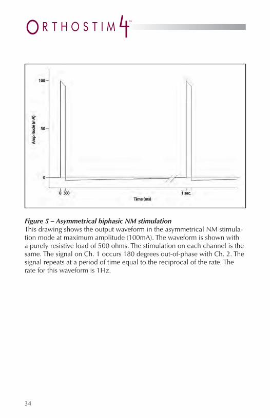
Figure 5 – Asymmetrical biphasic NM stimulationThis drawing shows the output waveform in the asymmetrical NM stimula-tion mode at maximum amplitude (100mA). The waveform is shown with a purely resistive load of 500 ohms. The stimulation on each channel is the same. The signal on Ch. 1 occurs 180 degrees out-of-phase with Ch. 2. The signal repeats at a period of time equal to the reciprocal of the rate. The rate for this waveform is 1Hz.

35
Figure 6—Pulsed Direct Current stimulationThis drawing shows the 277 Hz output waveform in the pulsed direct current stimulation mode at maximum amplitude (100mA). The waveform is shown with a purely resistive load of 500 ohms. The stimulation on each channel is the same.

36
Figure 7—Pulsed Direct Current stimulationThis drawing shows the 222 Hz output waveform in the pulsed direct current stimulation mode at maximum amplitude (100mA). The waveform is shown with a purely resistive load of 500 ohms. The stimulation on each channel is the same.

37
Troubleshooting:Problem Solution
Screen Displays:
Your prescribed time for authorized use of this equipment is now complete.
Your device needs to download information to VQ OrthoCare for your physician. Place the device in the cradle, turn it on and press (P) to Proceed with a download. If you do not have a cradle or this fails to correct the problem, contact Patient Care.
Screen Displays:
Your prescribed time for authorized use will expire in X days.
Your device needs to download information to VQ OrthoCare for your physician. Place the device in the cradle, turn it on and press (P) to Proceed with a download. If you do not have a cradle or this fails to correct the problem, contact Patient Care.
Device beeps and the screen says:
Error! Check your lead wires and electrodes
In most cases, this screen will appear when something becomes disconnected (e.g. lead wires or electrodes). Check the connections between the electrodes and your skin, the electrodes and the lead wire and the lead wire and the device. This error may also appear if the electrodes are too dry to adhere properly to your skin. In this case, replace the electrodes with a new set. When finished, press (P) to Proceed as directed on the screen. If none of these corrects the problem, contact Patient Care.
The device will not increase the intensity
This is most likely caused by the “lock out” feature that prevents accidental increases to your intensity. Press the (-) button to unlock the keypad, then (+) to increase the intensity to the desired level.
38
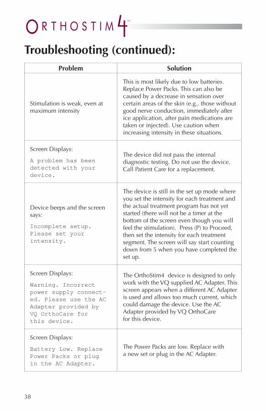
Troubleshooting (continued):Problem Solution
Stimulation is weak, even at maximum intensity
This is most likely due to low batteries. Replace Power Packs. This can also be caused by a decrease in sensation over certain areas of the skin (e.g., those without good nerve conduction, immediately after ice application, after pain medications are taken or injected). Use caution when increasing intensity in these situations.
Screen Displays:
A problem has been detected with your device.
The device did not pass the internal diagnostic testing. Do not use the device. Call Patient Care for a replacement.
Device beeps and the screen says:
Incomplete setup. Please set your intensity.
The device is still in the set up mode where you set the intensity for each treatment and the actual treatment program has not yet started (there will not be a timer at the bottom of the screen even though you will feel the stimulation). Press (P) to Proceed, then set the intensity for each treatment segment. The screen will say start counting down from 5 when you have completed the set up.
Screen Displays:
Warning. Incorrect power supply connect-ed. Please use the AC Adapter provided byVQ OrthoCare for this device.
The OrthoStim4 device is designed to only work with the VQ supplied AC Adapter. This screen appears when a different AC Adapter is used and allows too much current, which could damage the device. Use the AC Adapter provided by VQ OrthoCare for this device.
Screen Displays:
Battery Low. Replace Power Packs or plug in the AC Adapter.
The Power Packs are low. Replace with a new set or plug in the AC Adapter.

39
Notes:

40
Notes:

VQ OrthoCare is not liable for any misuse or misunderstanding of theOrthoStim4 product or operating manual. Please call your local representative if any additional assistance is required regarding this product and its operating instructions.
This patient manual is proprietary and confi dential. No part of this document may be reproduced or transmitted in any form or by any means, electronic or mechanical, including photocopy, recording or information storage and retrieval system, without permission in writing from VQ OrthoCare.
VQ OrthoCare warrants the OrthoStim4 to be free from electrical circuit defects in workmanship and materials for a period of three (3) years upon delivery to the customer. The case, cradle and belt clip are warranted to be free from defects in workmanship and materials for one (1) year upon delivery to the customer. VQ OrthoCare will repair or replace, at its facilities, any OrthoStim4 unit found to have become defective within the warranty period.
This warranty does not apply to accessories; specifi cally lead wires, electrodes, batteries, tapes, gel, carrying case and AC Adapter, nor does it apply to OrthoStim4 units that have been damaged due to misuse, or repaired or altered by parties other than VQ OrthoCare at its facilities.
This warranty is in lieu of any other warranties expressed or implied. No person or entity is authorized to bind VQ OrthoCare to any representa-tion of warranty other than those specifi cally set forth herein.
Warranty
41

Patient ManualOrthoStim4 Rehabilitative Electrotherapy
from VQ OrthoCare18011 Mitchell South, Irvine, CA 92614
Call 800.266.6969 Fax 800.821.8012www.vqorthocare.com
© 2010 VisionQuest Industries, Inc.VQO021578REVA