pat328, section 3, march 2001mar120, lecture 4, march 2001s16-1mar120, section 16, december 2001...
TRANSCRIPT

PAT328, Section 3, March 2001MAR120, Lecture 4, March 2001 S16-1MAR120, Section 16, December 2001
SECTION 16
HEAT TRANSFER ANALYSIS

PAT328, Section 3, March 2001MAR120, Lecture 4, March 2001 S16-2MAR120, Section 16, December 2001
TABLE OF CONTENTS (cont.)
Section Page
16.0 Heat Transfer AnalysisOverview …………………………………………………………………...………………………………………..
16-3Heat Transfer Modes …………………………..…………………………………………………………………..
16-4Heat Transfer Example ………………...…………………………...……………………………………………..
16-5Heat Transfer Mathematics ……………………...………………………………………………………………..
16-6Heat Transfer Loads & Boundary Conditions ………………………………………………………………….. 16-7Heat Transfer Initial Conditions ………………………………………………………………………………….. 16-10Heat Transfer In Msc.Patran Marc Preference ………………………………………………………..………..
16-11Thermal Nonlinear Analyses …………………………………………………………………………….………..
16-12Minimum Allowable Time Increment ……………………………………………………………………………..
16-13Minimum Time Increment:physical Interpretation ..……………………………………………………………..
16-14Difficulties With Time Incrementation ……………………………………..……………………………………..16-15Limitations and Capabilities……………………… ..…………………………………………………………….. 16-16Sequentially Coupled Problems …………………………………………………………………………………..
16-17Fully Coupled Problems ……………………………………….…………………………………………………..
16-18

PAT328, Section 3, March 2001MAR120, Lecture 4, March 2001 S16-3MAR120, Section 16, December 2001
OVERVIEW
Why a Structural Analyst may have to perform Thermal Analysis
Modes of Heat Transfer Available in MSC.Marcand MSC.Patran support
Conduction Convection Radiation Transient Analysis
versus Steady State Analysis
Linear versus Nonlinear Minimum Allowable Time
Increment Thermal Analysis How to calculate it Physical Interpretation What happens if you violate the
formula Sequentially Coupled Problems
versus
Fully Coupled Problems

PAT328, Section 3, March 2001MAR120, Lecture 4, March 2001 S16-4MAR120, Section 16, December 2001
Motivation
When the solution for the temperature field in a solid (or fluid) is desired,and is not influenced by the other unknown fields, heat transfer analysis is appropriate.
HEAT TRANSFER MODES
Boundary Conditions:
Thermal Convection
Natural convection
Radiation
Near a Contact add:
Distance dependent convection
Q = hcv*(T2-T1)+hnt*(T2-T1)ent +
**(T24-T14) +
(hct – (hct-hbl)*gap/dqnear)*(T2-T1)

PAT328, Section 3, March 2001MAR120, Lecture 4, March 2001 S16-5MAR120, Section 16, December 2001
HEAT TRANSFER EXAMPLE
Computed Temperatures
Temperature given at bottom left and right end surfaces
Convection given about connector Example: Steady State Analysis of Radiator (Workshop 5)
PAT328, Section 3, March 2001MAR120, Lecture 4, March 2001 S16-6MAR120, Section 16, December 2001
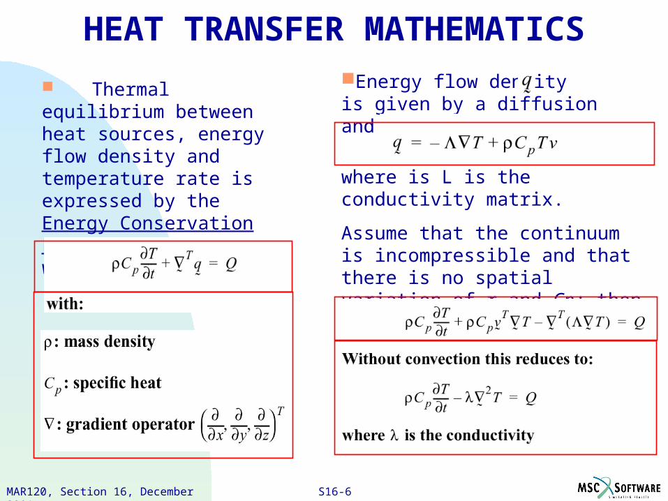
Thermal equilibrium between heat sources, energy flow density and temperature rate is expressed by the Energy Conservation Law, which may be written:
Energy flow density is given by a diffusion and convection part:
where is L is the conductivity matrix.
Assume that the continuum is incompressible and that there is no spatial variation of r and Cp; then the conservation law becomes:
HEAT TRANSFER MATHEMATICS

PAT328, Section 3, March 2001MAR120, Lecture 4, March 2001 S16-7MAR120, Section 16, December 2001
HEAT TRANSFER LOADS & BOUNDARY CONDITIONS

PAT328, Section 3, March 2001MAR120, Lecture 4, March 2001 S16-8MAR120, Section 16, December 2001
contact
HEAT TRANSFER LOADS & BOUNDARY CONDITIONS (CONT.)

PAT328, Section 3, March 2001MAR120, Lecture 4, March 2001 S16-9MAR120, Section 16, December 2001
contact6) Contact conduction:
h : Transfer coeff.
= Temp.Body 2 = Temp.Body 1
HEAT TRANSFER LOADS & BOUNDARY CONDITIONS (CONT.)
PAT328, Section 3, March 2001MAR120, Lecture 4, March 2001 S16-10MAR120, Section 16, December 2001
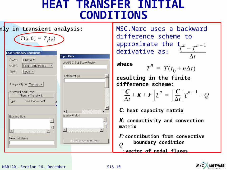
Only in transient analysis: MSC.Marc uses a backward difference scheme to approximate the time derivative as:
resulting in the finite difference scheme:
where
C: heat capacity matrix
K: conductivity and convection matrix
F: contribution from convective boundary condition
: vector of nodal fluxes
HEAT TRANSFER INITIAL CONDITIONS
PAT328, Section 3, March 2001MAR120, Lecture 4, March 2001 S16-11MAR120, Section 16, December 2001
HEAT TRANSFER IN MSC.PATRAN MARC PREFERENCE
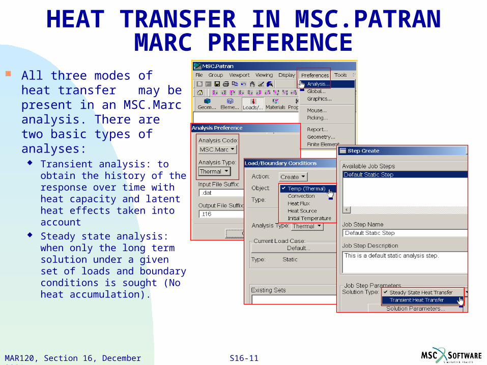
All three modes of heat transfer may be present in an MSC.Marc analysis. There are two basic types of analyses:
Transient analysis: to obtain the history of the response over time with heat capacity and latent heat effects taken into account
Steady state analysis: when only the long term solution under a given set of loads and boundary conditions is sought (No heat accumulation).
PAT328, Section 3, March 2001MAR120, Lecture 4, March 2001 S16-12MAR120, Section 16, December 2001
Time
Temperature
THERMAL NONLINEAR ANALYSES
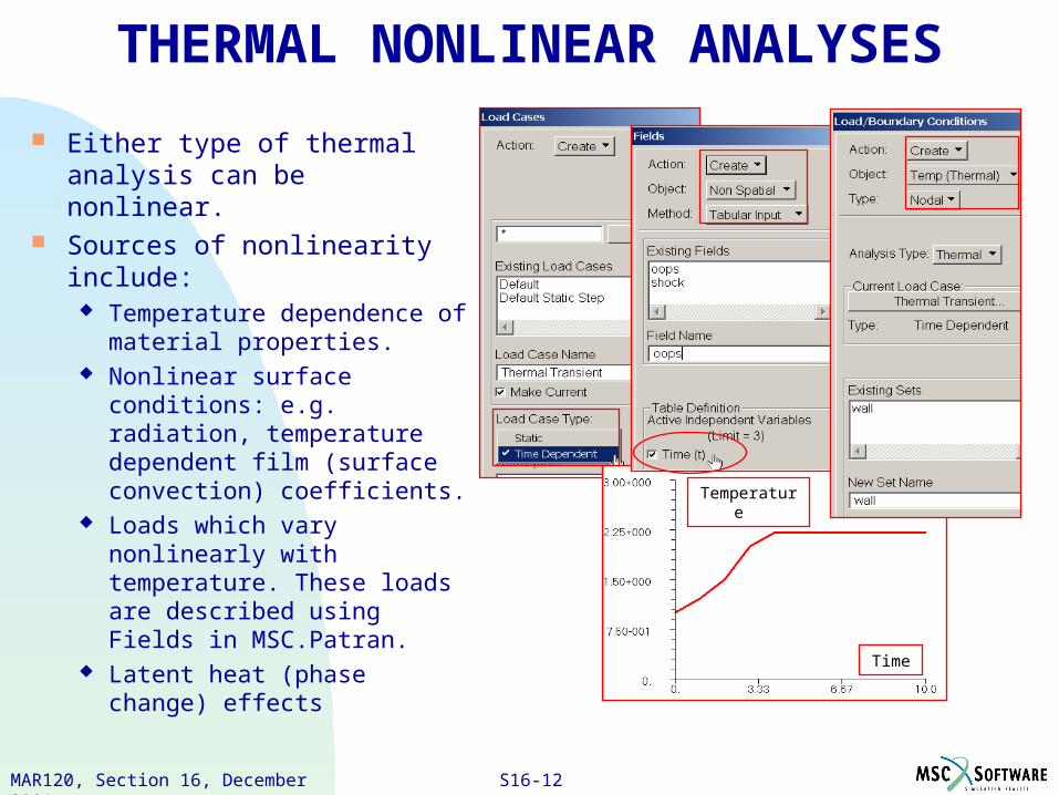
Either type of thermal analysis can be nonlinear.
Sources of nonlinearity include:
Temperature dependence of material properties.
Nonlinear surface conditions: e.g. radiation, temperature dependent film (surface convection) coefficients.
Loads which vary nonlinearly with temperature. These loads are described using Fields in MSC.Patran.
Latent heat (phase change) effects
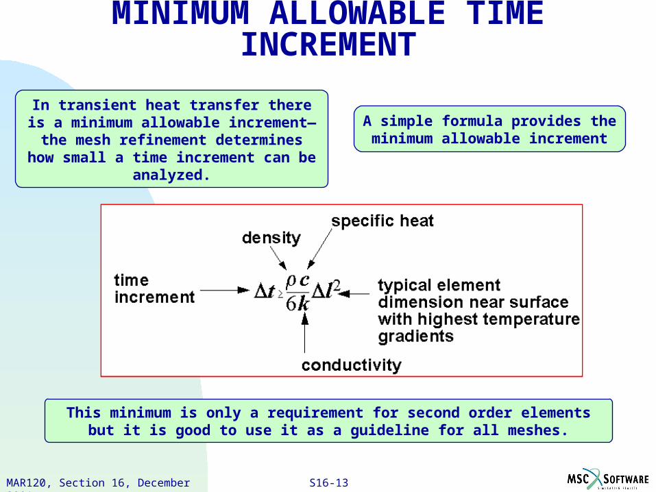
PAT328, Section 3, March 2001MAR120, Lecture 4, March 2001 S16-13MAR120, Section 16, December 2001
In transient heat transfer there is a minimum allowable increment— the mesh refinement determines how small a time
increment can be analyzed.
A simple formula provides the minimum allowable increment
This minimum is only a requirement for second order elements but it is good to use it as a guideline for all meshes.
MINIMUM ALLOWABLE TIME INCREMENT

PAT328, Section 3, March 2001MAR120, Lecture 4, March 2001 S16-14MAR120, Section 16, December 2001
This expression describes the physical limitation on the amount of heat that
can be moved a distance l in an
amount of time t
Think of the temperature at each node representing the amount of heat in the physical region of that node
Then think of the amount of heat associated with each individual node
MINIMUM TIME INCREMENT: PHYSICAL INTERPRETATION
If you specify a higher temperature at node A than as at node E (as the only boundary conditions) heat must be removed from nodes B and C to comply with the specified boundary condition at node A.
If t is too small, or l too large, to allow enough heat to move to node C, the extra heat required to comply with the specified temperature boundary condition must come from the region of node B.
If too much heat is removed from node B, the temperature drops below the physically realistic value and you see a seesaw pattern of temperature distribution rather than the correct monotonically decreasing one.
A B C D E
2
6l
k
pct
PAT328, Section 3, March 2001MAR120, Lecture 4, March 2001 S16-15MAR120, Section 16, December 2001
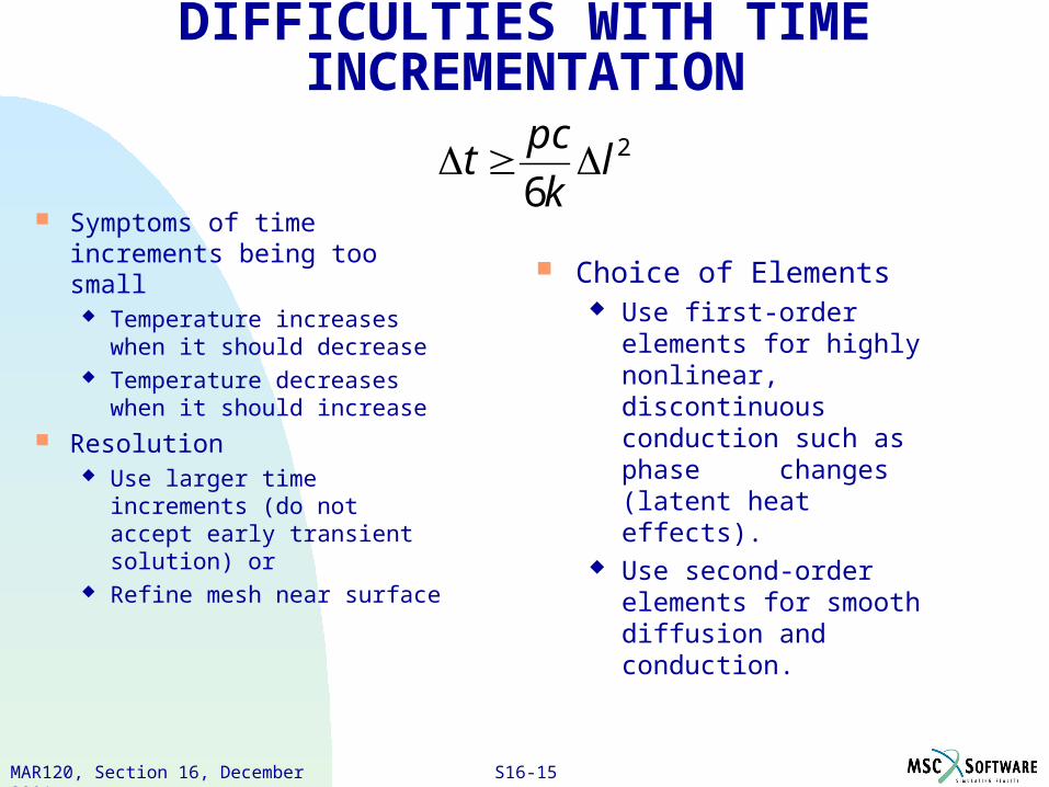
DIFFICULTIES WITH TIME INCREMENTATION
Symptoms of time increments being too small
Temperature increases when it should decrease
Temperature decreases when it should increase
Resolution Use larger time increments
(do not accept early transient solution) or
Refine mesh near surface
Choice of Elements Use first-order elements for
highly nonlinear, discontinuous conduction such as phase changes (latent heat effects).
Use second-order elements for smooth diffusion and conduction.
2
6l
k
pct
PAT328, Section 3, March 2001MAR120, Lecture 4, March 2001 S16-16MAR120, Section 16, December 2001
LIMITATIONS AND CAPABILITIES
Limitation: As discussed, oscillatory behavior will likely result if time step is too small.
Better approximation can be obtained if:
time step is INCREASED mesh is refined heat capacity matrix is lumped
(linear elements) Further MARC capabilities:
User subroutines for non-linear boundary conditions
tying and heat transfer shell element with parabolic distribution in thickness direction
phase transitions

PAT328, Section 3, March 2001MAR120, Lecture 4, March 2001 S16-17MAR120, Section 16, December 2001
SEQUENTIALLY COUPLED PROBLEMS
Thermal field affects the mechanical field
Mechanical properties change with temperature
Thermal expansion Sequentially coupled problems
are supported in MSC.Marc 2001and by MSC.Patran 2001
Mechanical field does not affect the thermal field.
Temperatures may be applied directly as a Load/Boundary Condition, or be read from a file using PCL.
PAT328, Section 3, March 2001MAR120, Lecture 4, March 2001 S16-18MAR120, Section 16, December 2001
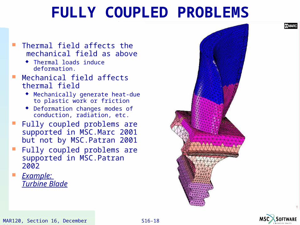
FULLY COUPLED PROBLEMS
Thermal field affects the mechanical field as above
Thermal loads induce deformation. Mechanical field affects thermal
field Mechanically generate heat-due to
plastic work or friction Deformation changes modes of
conduction, radiation, etc. Fully coupled problems are
supported in MSC.Marc 2001 but not by MSC.Patran 2001
Fully coupled problems are supported in MSC.Patran 2002
Example: Turbine Blade
PAT328, Section 3, March 2001MAR120, Lecture 4, March 2001 S16-19MAR120, Section 16, December 2001
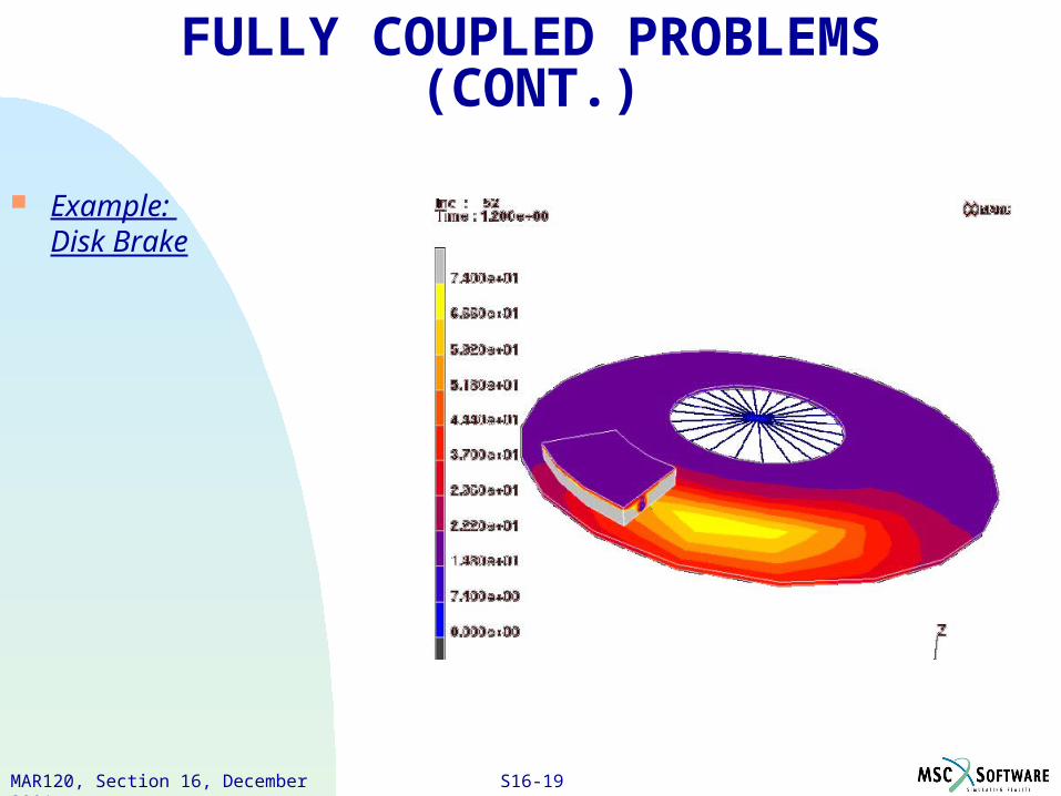
FULLY COUPLED PROBLEMS (CONT.)
Example: Disk Brake
PAT328, Section 3, March 2001MAR120, Lecture 4, March 2001 S16-20MAR120, Section 16, December 2001
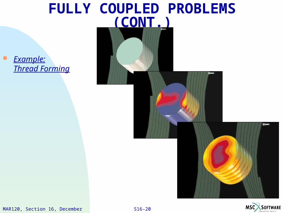
FULLY COUPLED PROBLEMS (CONT.)
Example:Thread Forming