s6-1pat328, section 3, march 2001mar120, section 6, december 2001 section 6 nonlinearity
TRANSCRIPT

S6-1PAT328, Section 3, March 2001MAR120, Section 6, December 2001
SECTION 6
NONLINEARITY
S6-2PAT328, Section 3, March 2001MAR120, Section 6, December 2001
TABLE OF CONTENTS
Section Page
6.0 NonlinearityWhat Causes Nonlinearities In Structural Mechanics (P Ku)………………………………………………..
6-3 Example: Linear Spring……………………………………………………………………………………………
6-5Example: Nonlinear Spring………………………………………………………………………………………..
6-6Using Finite Element Analysis To Solve Nonlinear Problems: Collapse Example………………………… 6-7 Using Finite Element Analysis To Solve Nonlinear Problems: Gap Contact…………………………………6-8Multiple Sources Of Nonlinearity…………………………………………………………………………………. 6-9Contact Nonlinearity……………………………………………………………………………………………….. 6-10 Contact Element Library: Gap Elements…………………………………………………………………………6-14Gap Element Definition……………………………………………………………………………………………. 6-15 Remarks On Gap Elements………………………………………………………………………………………..
6-18 Geometric Nonlinearity……………………………………………………………………………………………..
6-19Material And Geometric Nonlinearity……………………………………………………………………………..6-20Example Of Geometric Nonlinear Analysis:Blade On A Jet Engine………………………………………… 6-21Example Of Geometric Nonlinear Analysis: Lateral Collapse Of Flat Beam……………………………….. 6-22Example Of Material, Contact and Geometric Nonlinear Analysis: Punching A Thin Shell….…………... 6-23Major Difficulties in Nonlinear Analysis…………………………………………………………..l..…………... 6-24
S6-3PAT328, Section 3, March 2001MAR120, Section 6, December 2001
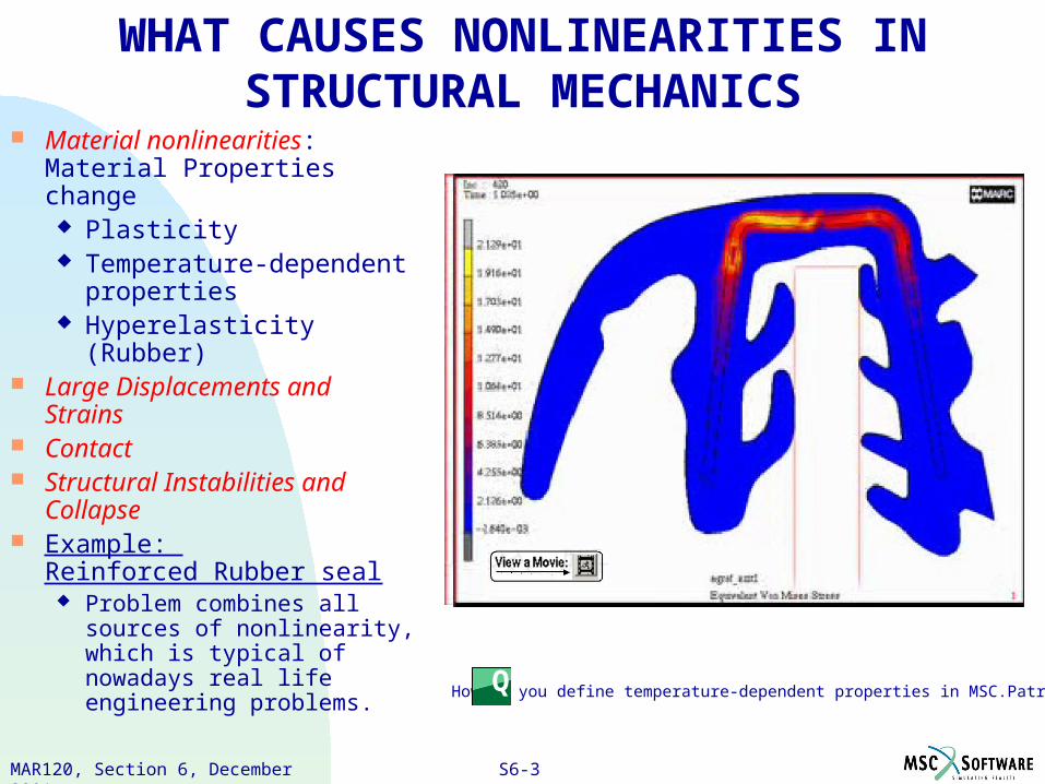
How do you define temperature-dependent properties in MSC.Patran?Q
WHAT CAUSES NONLINEARITIES IN STRUCTURAL MECHANICS
Material nonlinearities: Material Properties change Plasticity Temperature-dependent
properties Hyperelasticity (Rubber)
Large Displacements and Strains
Contact Structural Instabilities and
Collapse Example:
Reinforced Rubber seal Problem combines all
sources of nonlinearity, which is typical of nowadays real life engineering problems.
S6-4PAT328, Section 3, March 2001MAR120, Section 6, December 2001 S6-4
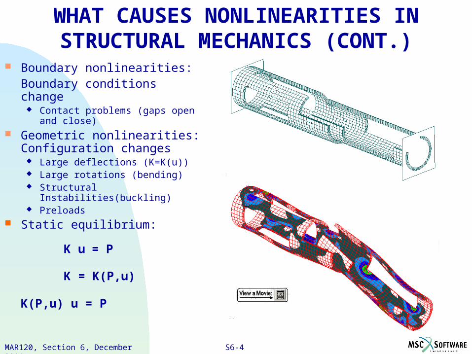
WHAT CAUSES NONLINEARITIES IN STRUCTURAL MECHANICS (CONT.)
Boundary nonlinearities:Boundary conditions change
Contact problems (gaps open and close)
Geometric nonlinearities: Configuration changes
Large deflections (K=K(u)) Large rotations (bending) Structural Instabilities(buckling) Preloads
Static equilibrium:
K u = P
K = K(P,u)
K(P,u) u = P
S6-5PAT328, Section 3, March 2001MAR120, Section 6, December 2001
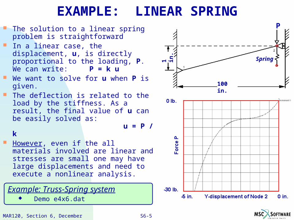
EXAMPLE: LINEAR SPRING The solution to a linear spring problem
is straightforward In a linear case, the displacement, u, is
directly proportional to the loading, P. We can write: P = k u
We want to solve for u when P is given.
The deflection is related to the load by the stiffness. As a result, the final value of u can be easily solved as: u = P / k
However, even if the all materials involved are linear and stresses are small one may have large displacements and need to execute a nonlinear analysis.
Spring
P
100 in.
1 in.
Example: Truss-Spring system Demo e4x6.dat
S6-6PAT328, Section 3, March 2001MAR120, Section 6, December 2001
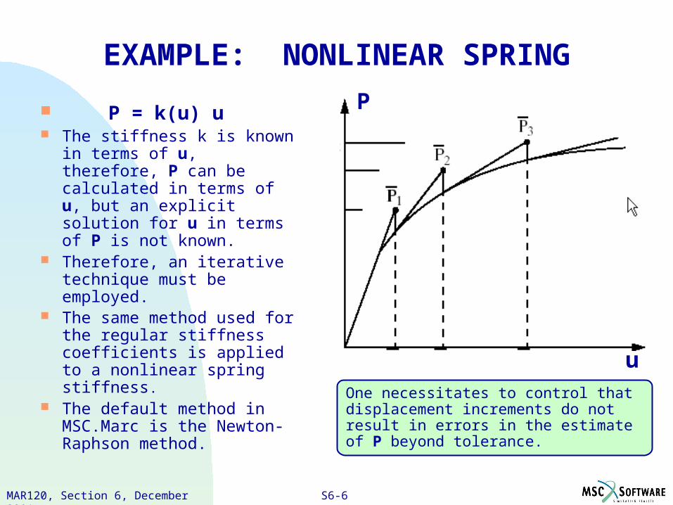
EXAMPLE: NONLINEAR SPRING
P = k(u) u The stiffness k is known in
terms of u, therefore, P can be calculated in terms of u, but an explicit solution for u in terms of P is not known.
Therefore, an iterative technique must be employed.
The same method used for the regular stiffness coefficients is applied to a nonlinear spring stiffness.
The default method in MSC.Marc is the Newton-Raphson method.
P
u
One necessitates to control that displacement increments do not result in errors in the estimate of P beyond tolerance.
S6-7PAT328, Section 3, March 2001MAR120, Section 6, December 2001
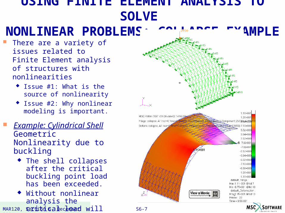
USING FINITE ELEMENT ANALYSIS TO SOLVE NONLINEAR PROBLEMS: COLLAPSE EXAMPLE
There are a variety of issues related to Finite Element analysis of structures with nonlinearities
Issue #1: What is the source of nonlinearity
Issue #2: Why nonlinear modeling is important.
Example: Cylindrical Shell Geometric Nonlinearity due to buckling
The shell collapses after the critical buckling point load has been exceeded.
Without nonlinear analysis the critical load will be overestimates –dangerous.
S6-8PAT328, Section 3, March 2001MAR120, Section 6, December 2001
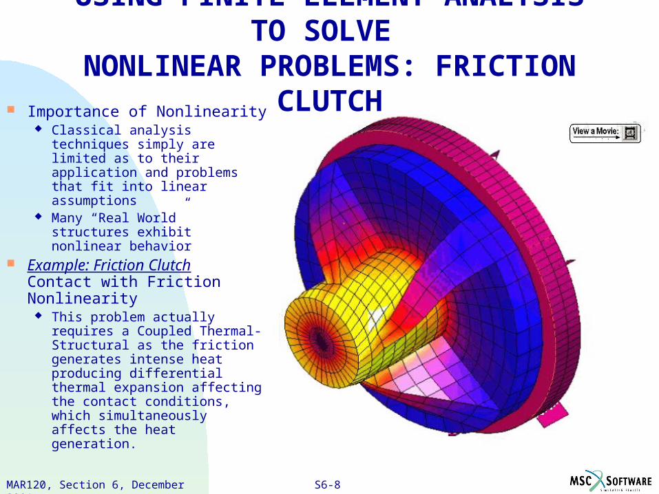
USING FINITE ELEMENT ANALYSIS TO SOLVE NONLINEAR PROBLEMS: FRICTION CLUTCH
Importance of Nonlinearity Classical analysis techniques
simply are limited as to their application and problems that fit into linear assumptions
Many “Real World” structures exhibit nonlinear behavior
Example: Friction ClutchContact with Friction Nonlinearity
This problem actually requires a Coupled Thermal-Structural as the friction generates intense heat producing differential thermal expansion affecting the contact conditions, which simultaneously affects the heat generation.
S6-9PAT328, Section 3, March 2001MAR120, Section 6, December 2001
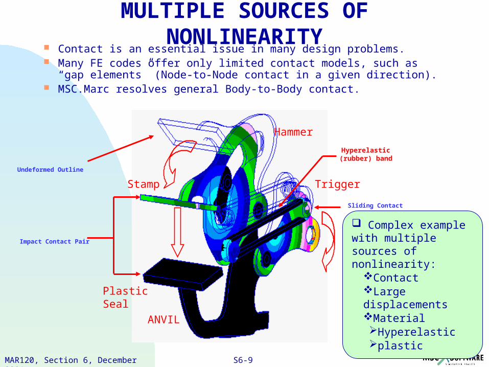
Complex example with multiple sources of nonlinearity:
ContactLarge displacementsMaterial Hyperelasticplastic
MULTIPLE SOURCES OF NONLINEARITY Contact is an essential issue in many design problems. Many FE codes offer only limited contact models, such as
“gap elements” (Node-to-Node contact in a given direction). MSC.Marc resolves general Body-to-Body contact.
Undeformed Outline
Impact Contact Pair
Hyperelastic (rubber) band
Sliding Contact
Plastic Seal
ANVIL
Trigger
Hammer
Stamp
S6-10PAT328, Section 3, March 2001MAR120, Section 6, December 2001
LINE VARIABLE SCALE FACTOR
1 X-ANGVEL 1 +1.00E+00
CONTACT NONLINEARITY
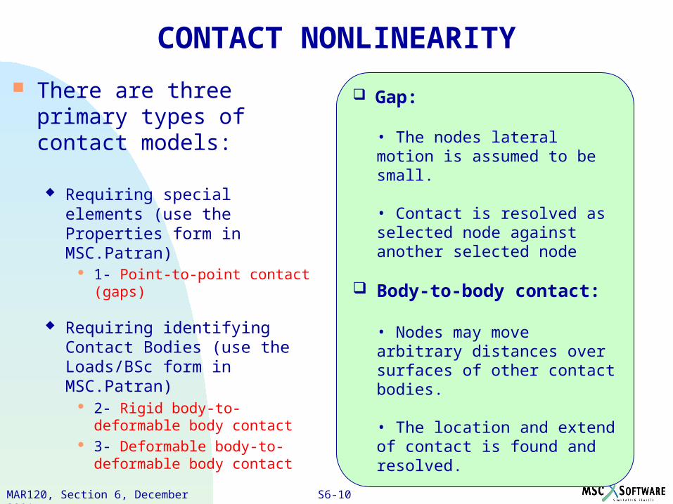
There are three primary types of contact models:
Requiring special elements (use the Properties form in MSC.Patran)
1- Point-to-point contact (gaps)
Requiring identifying Contact Bodies (use the Loads/BSc form in MSC.Patran)
2- Rigid body-to-deformable body contact
3- Deformable body-to-deformable body contact
Gap:
• The nodes lateral motion is assumed to be small.
• Contact is resolved as selected node against another selected node
Body-to-body contact:
• Nodes may move arbitrary distances over surfaces of other contact bodies.
• The location and extend of contact is found and resolved.
S6-11PAT328, Section 3, March 2001MAR120, Section 6, December 2001
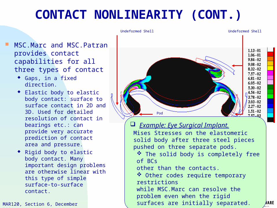
Undeformed Shell
Pod
Undeformed Shell
CONTACT NONLINEARITY (CONT.)
MSC.Marc and MSC.Patran provides contact capabilities for all three types of contact
Gaps, in a fixed direction. Elastic body to elastic body
contact: surface to surface contact in 2D and 3D. Used for detailed resolution of contact in bearings etc.: can provide very accurate prediction of contact area and pressure.
Rigid body to elastic body contact. Many important design problems are otherwise linear with this type of simple surface-to-surface contact.
Example: Eye Surgical Implant.Mises Stresses on the elastomeric solid body after three steel pieces pushed on three separate pods. The solid body is completely free of BCs other than the contacts. Other codes require temporary restrictionswhile MSC.Marc can resolve the problem even when the rigid surfaces are initially separated.
S6-12PAT328, Section 3, March 2001MAR120, Section 6, December 2001
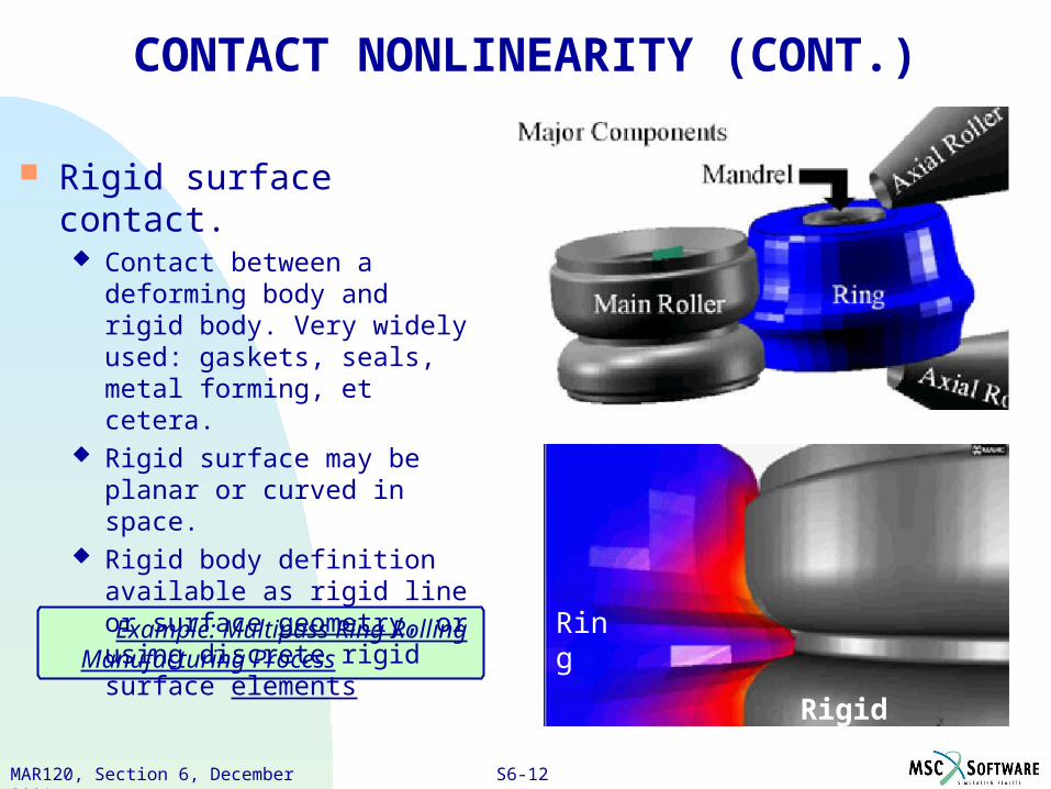
Example: Multipass Ring Rolling Manufacturing Process
CONTACT NONLINEARITY (CONT.)
Rigid surface contact. Contact between a deforming
body and rigid body. Very widely used: gaskets, seals, metal forming, et cetera.
Rigid surface may be planar or curved in space.
Rigid body definition available as rigid line or surface geometry, or using discrete rigid surface elements
Rigid Surface
Ring
S6-13PAT328, Section 3, March 2001MAR120, Section 6, December 2001
CONTACT NONLINEARITY (CONT.)
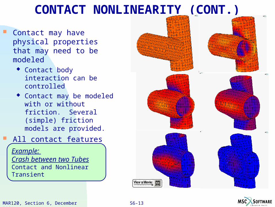
Contact may have physical properties that may need to be modeled
Contact body interaction can be controlled
Contact may be modeled with or without friction. Several (simple) friction models are provided.
All contact features work with dynamics (impact) as well as
statics.
Example: Crash between two TubesContact and Nonlinear Transient
S6-14PAT328, Section 3, March 2001MAR120, Section 6, December 2001
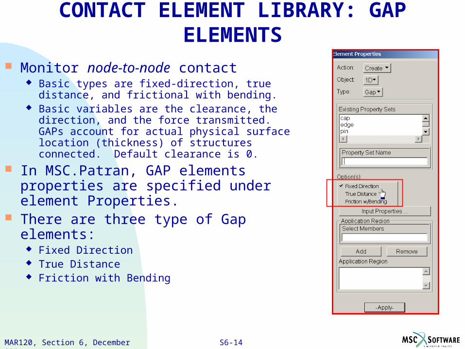
CONTACT ELEMENT LIBRARY: GAP ELEMENTS
Monitor node-to-node contact Basic types are fixed-direction, true distance,
and frictional with bending. Basic variables are the clearance, the direction,
and the force transmitted. GAPs account for actual physical surface location (thickness) of structures connected. Default clearance is 0.
In MSC.Patran, GAP elements properties are specified under element Properties.
There are three type of Gap elements: Fixed Direction True Distance Friction with Bending
S6-15PAT328, Section 3, March 2001MAR120, Section 6, December 2001
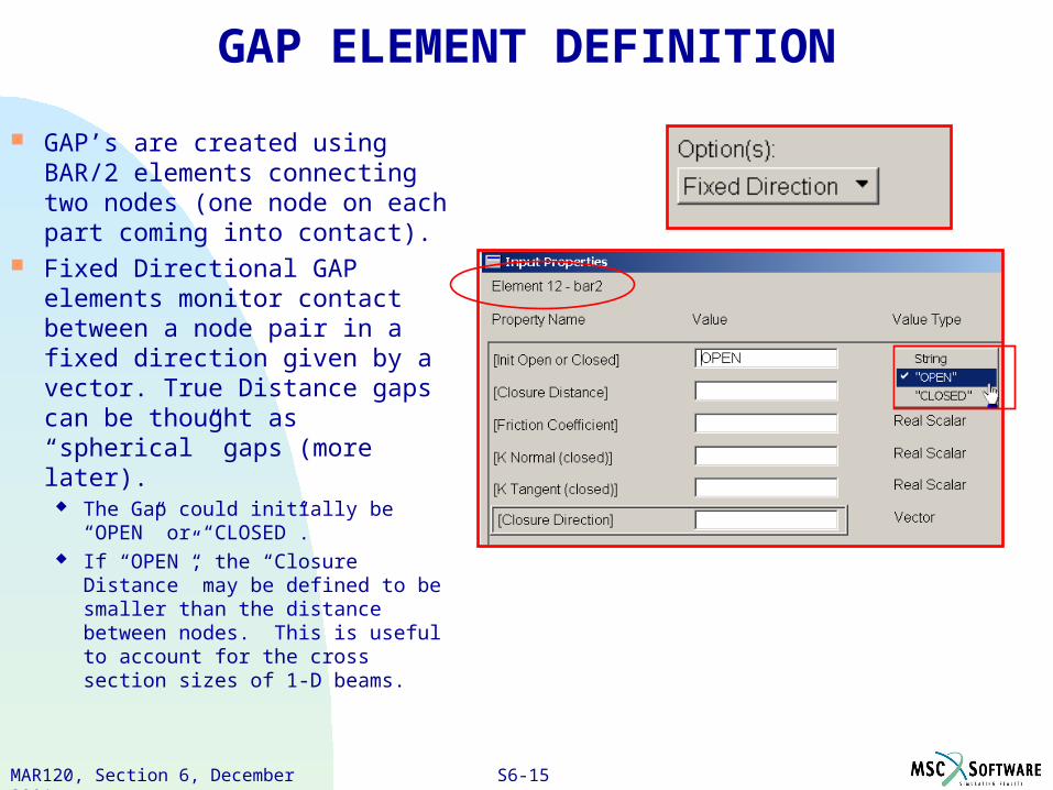
GAP ELEMENT DEFINITION
GAP’s are created using BAR/2 elements connecting two nodes (one node on each part coming into contact).
Fixed Directional GAP elements monitor contact between a node pair in a fixed direction given by a vector. True Distance gaps can be thought as “spherical” gaps (more later).
The Gap could initially be “OPEN” or “CLOSED”.
If “OPEN”, the “Closure Distance” may be defined to be smaller than the distance between nodes. This is useful to account for the cross section sizes of 1-D beams.
S6-16PAT328, Section 3, March 2001MAR120, Section 6, December 2001
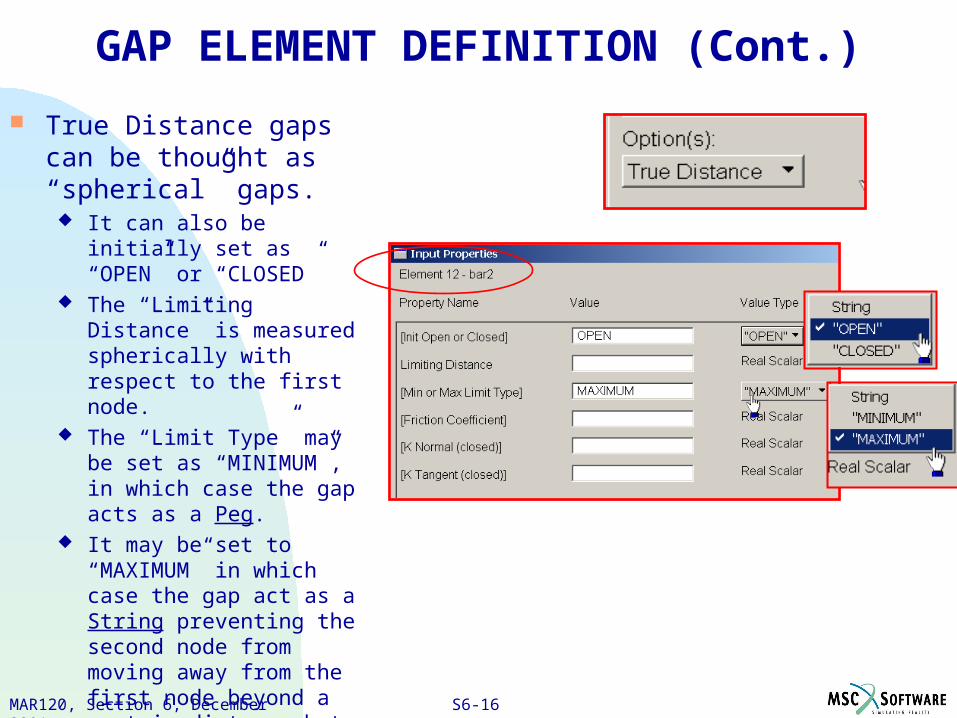
GAP ELEMENT DEFINITION (Cont.)
True Distance gaps can be thought as “spherical” gaps.
It can also be initially set as “OPEN” or “CLOSED”
The “Limiting Distance” is measured spherically with respect to the first node.
The “Limit Type” may be set as “MINIMUM”, in which case the gap acts as a Peg.
It may be set to “MAXIMUM” in which case the gap act as a String preventing the second node from moving away from the first node beyond a certain distance but allowing the nodes to come together.
S6-17PAT328, Section 3, March 2001MAR120, Section 6, December 2001
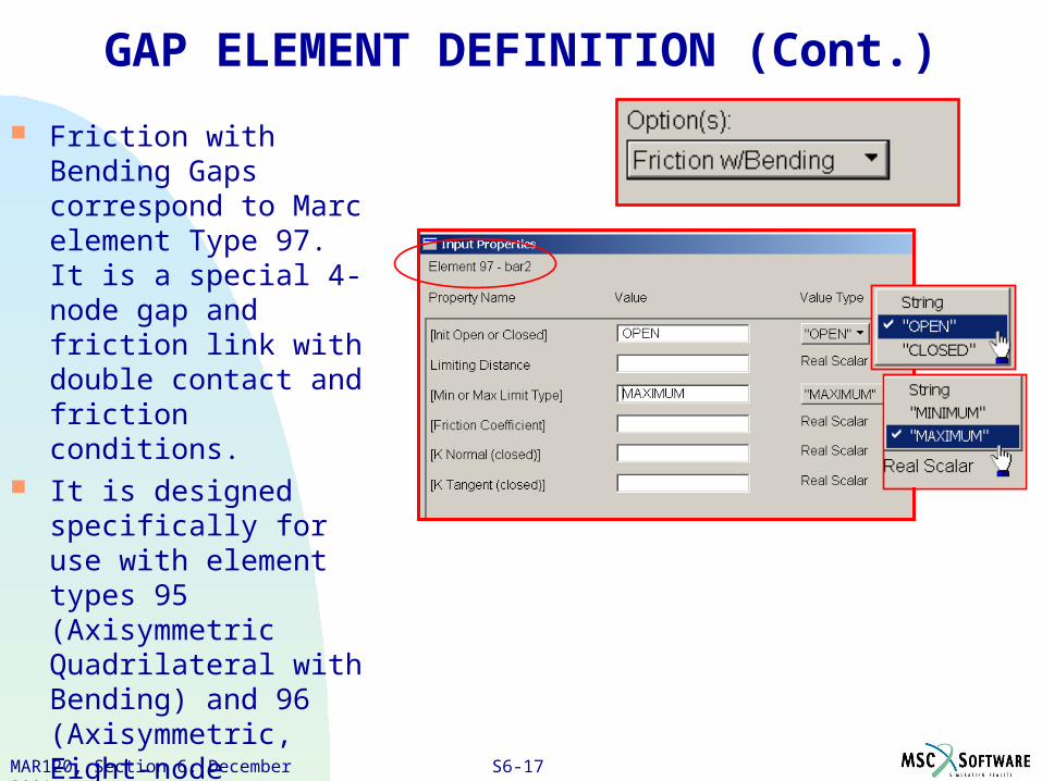
GAP ELEMENT DEFINITION (Cont.)
Friction with Bending Gaps correspond to Marc element Type 97. It is a special 4-node gap and friction link with double contact and friction conditions.
It is designed specifically for use with element types 95 (Axisymmetric Quadrilateral with Bending) and 96 (Axisymmetric, Eight-node Distorted Quadrilateral with Bending).
S6-18PAT328, Section 3, March 2001MAR120, Section 6, December 2001
REMARKS ON GAP ELEMENTS
Gap Elements have unit area, so the contact “stress” calculated is actually the contact force—Don’t use gap elements for large surface-to-surface contact. Use them when contact is point-to-point
For Fixed Directional GAP elements, contact depends only on initial clearance and the relative displacements of the two nodes in the direction of contact.
Initial coordinates are not used at all to define initial clearance
Initial interference can be specified by using a congruent (although not equivalent) mesh with a negative Initial Clearance value
If the nodes are not coincident, MSC.Marc will calculate the closure direction as being from node1 to node2 based on their initial positions if you put <0, 0, 0> in as the closure direction
For other gap elements, depending on the initial coordinates and the specified clearance, they may start in an open or closed state.
S6-19PAT328, Section 3, March 2001MAR120, Section 6, December 2001
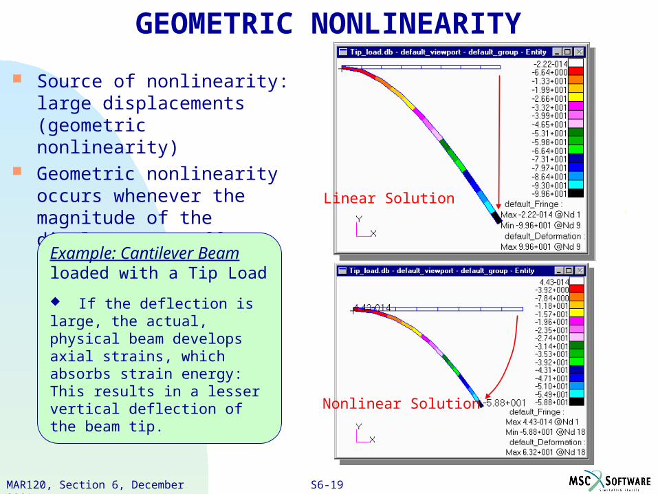
GEOMETRIC NONLINEARITY
Source of nonlinearity: large displacements (geometric nonlinearity)
Geometric nonlinearity occurs whenever the magnitude of the displacements affects the response of the structure.
Example: Cantilever Beam loaded with a Tip Load
If the deflection is large, the actual, physical beam develops axial strains, which absorbs strain energy: This results in a lesser vertical deflection of the beam tip.
Linear Solution
Nonlinear Solution
S6-20PAT328, Section 3, March 2001MAR120, Section 6, December 2001
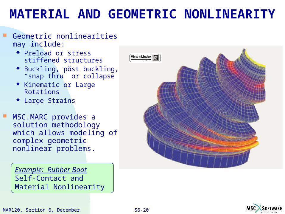
Example: Rubber BootSelf-Contact and Material Nonlinearity
MATERIAL AND GEOMETRIC NONLINEARITY
Geometric nonlinearities may include:
Preload or stress stiffened structures
Buckling, post buckling, “snap thru” or collapse
Kinematic or Large Rotations Large Strains
MSC.MARC provides a solution methodology which allows modeling of complex geometric nonlinear problems.
S6-21PAT328, Section 3, March 2001MAR120, Section 6, December 2001
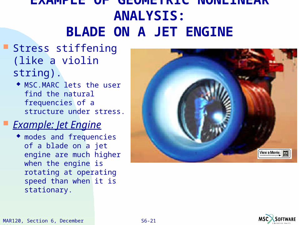
Stress stiffening (like a violin string). MSC.MARC lets the user
find the natural frequencies of a structure under stress.
Example: Jet Engine modes and frequencies of
a blade on a jet engine are much higher when the engine is rotating at operating speed than when it is stationary.
EXAMPLE OF GEOMETRIC NONLINEAR ANALYSIS:BLADE ON A JET ENGINE
S6-22PAT328, Section 3, March 2001MAR120, Section 6, December 2001
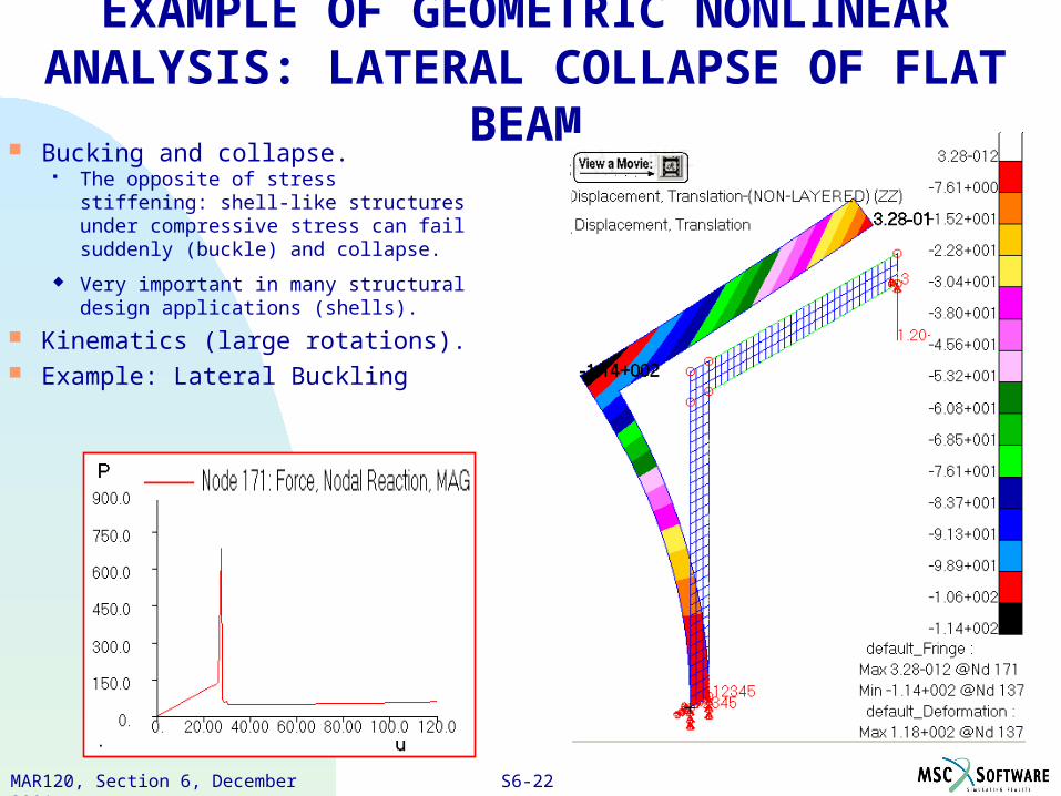
Bucking and collapse. The opposite of stress stiffening:
shell-like structures under compressive stress can fail suddenly (buckle) and collapse.
Very important in many structural design applications (shells).
Kinematics (large rotations). Example: Lateral Buckling
EXAMPLE OF GEOMETRIC NONLINEAR ANALYSIS: LATERAL COLLAPSE OF FLAT BEAM
S6-23PAT328, Section 3, March 2001MAR120, Section 6, December 2001
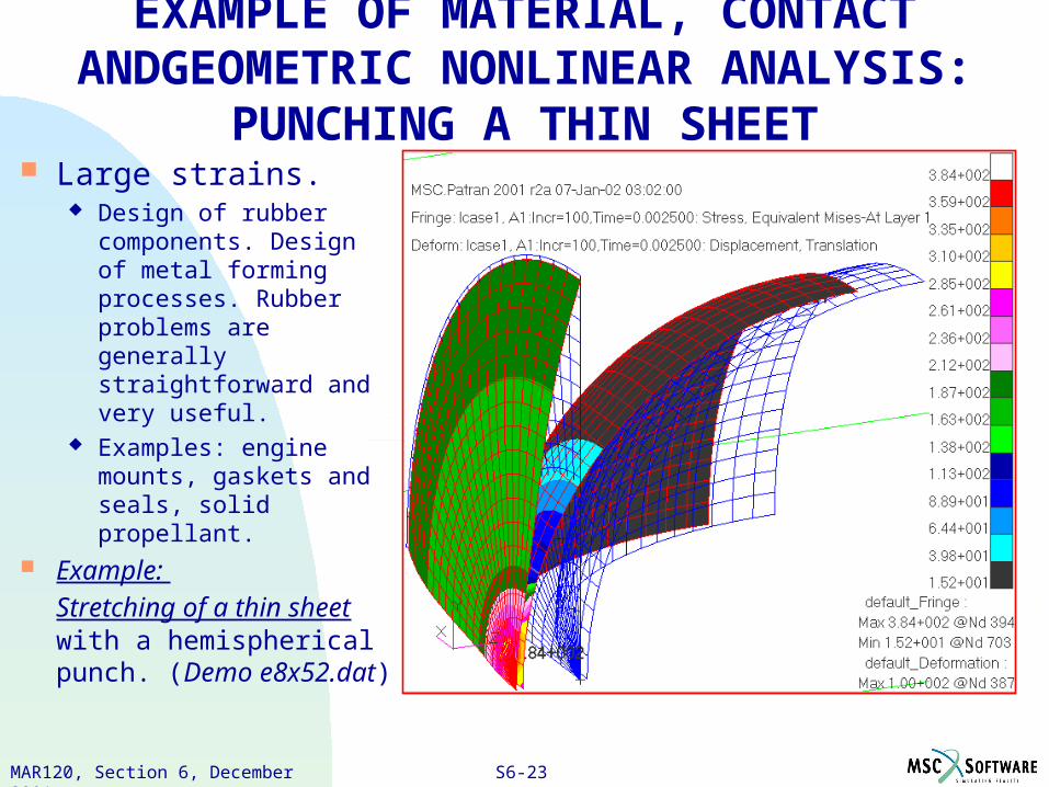
Large strains. Design of rubber
components. Design of metal forming processes. Rubber problems are generally straightforward and very useful.
Examples: engine mounts, gaskets and seals, solid propellant.
Example:
Stretching of a thin sheet with a hemispherical punch. (Demo e8x52.dat)
EXAMPLE OF MATERIAL, CONTACT ANDGEOMETRIC NONLINEAR ANALYSIS: PUNCHING A THIN SHEET
S6-24PAT328, Section 3, March 2001MAR120, Section 6, December 2001
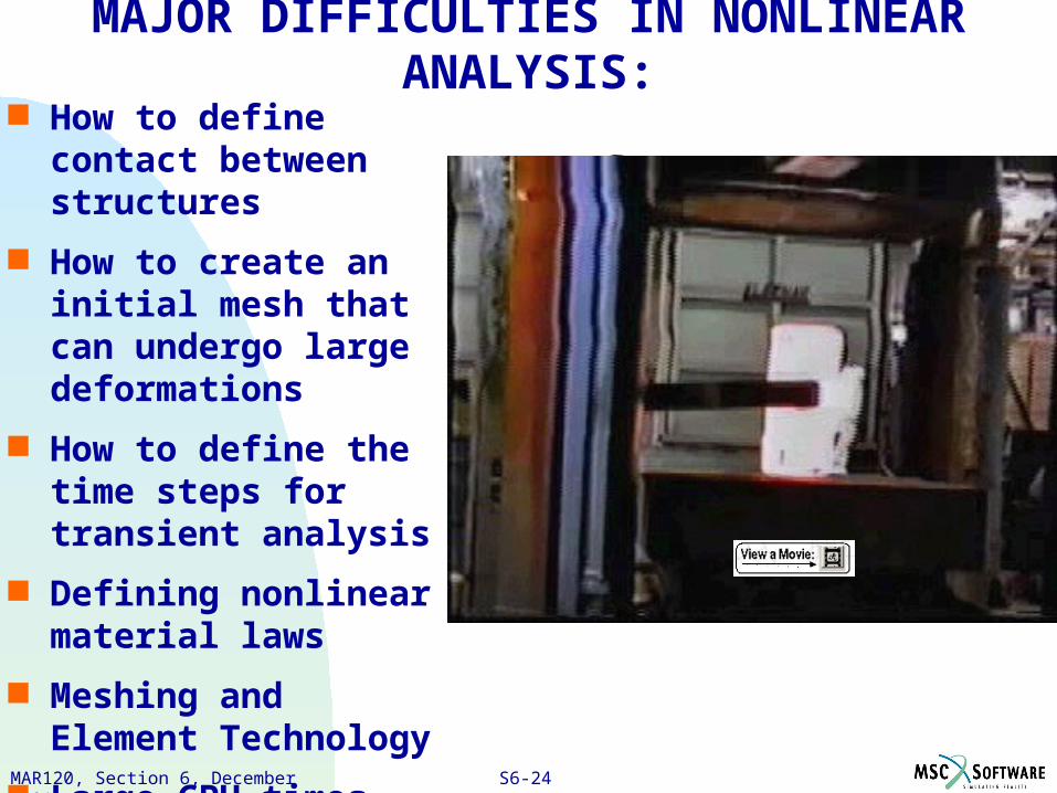
MAJOR DIFFICULTIES IN NONLINEAR ANALYSIS: How to define contact
between structures
How to create an initial mesh that can undergo large deformations
How to define the time steps for transient analysis
Defining nonlinear material laws
Meshing and Element Technology
Large CPU times