passport pr surgical protocol - bizwan.com passport pr surgical... · surgical protocol for the...
TRANSCRIPT
Passport® PR Surgical Protocol
Scorpio Total Knee System


Table of Contents
TIBIAL PREPARATION ..............................................................21
Tibial External Alignment Option ..............................................21
Tibial Resection Level ...................................................................24
Proximal Tibial Resection ............................................................26
Tibial Intramedullary Alignment Option ..................................27
Entry Hole and IM Rod Position ................................................27
IM Rod Placement.........................................................................28
Tibial Resection Level ...................................................................29
Proximal Tibial Resection ............................................................32
DELTAFIT KEEL PREPARATION .............................................33
Tibial Component Sizing ..............................................................33
Tibial Component Alignment .....................................................34
Tibial Keel Punching ....................................................................36
All-Poly Tibial Punching ..............................................................38
Tibial Punching Sequence ............................................................39
COMPONENT IMPLANTATION ............................................39
Tibial Component .........................................................................40
Tibial Bearing Insert Assembly ...................................................41
Femoral Component .....................................................................41
Closure ............................................................................................41
POST-OPERATIVE CARE, INDICATIONS, CONTRAINDICATIONS AND WARNINGS ..........................42
i
Scorpio Total Knee System Surgical Protocol for the Passport Instruments
ExPOSuRE ...................................................................................2
FEMORAL PREPARATION .......................................................3
Femoral Intramedullary Alignment ...........................................3
Femoral IM Alignment .................................................................4
Distal Femoral Resection Level ...................................................5
Distal Femoral Resection .............................................................7
Femoral A/P Sizing .......................................................................8
Alternate Sizing Methods .............................................................9
Femoral Component Rotation .....................................................10
Femoral Anterior, Posterior and Chamfer Resections .............12
SCORPIO uNIVERSAL PREPARATION BLOCK ..................14
For Posterior Stabilized Knees .....................................................15
Notch Preparation Option 1 Punch Technique ...........................................................................15
Notch Preparation Option 2 Saw Technique ...............................................................................16
Notch Compacting Preparation ..................................................17
For Posterior Stabilized and Cruciate Retaining Knees ...........18
Patella Recess Preparation Option 1 Punch Technique ...........................................................................18
Patella Recess Preparation Option 2 Rasp Technique ..............................................................................19
Assessment of Fit ...........................................................................20

Stryker Corporation also wishes to thank the following orthopaedic surgeons for their assistance in the development of the Passport Instrumentation Surgical Protocol.
Richard J. Fingeroth, M.D.New England Orthopaedic SurgeonsSpringfield, MassachusettsClinical Instructor of OrthopaedicsBoston university of Medicine Boston, Massachusetts
Lawrence G. Morawa, M.D.Assistant Professor, Wayne State universityDearborn, Michigan
Hugh B. Morris, M.D.Associate, Jewett Orthopaedic ClinicFlorida Hospital and Winter Park Memorial HospitalOrlando/Winter Park, Florida
Donald T. Reilly, M.D., Ph.D.Assistant Professor of Orthopaedic Surgery Harvard Medical School, Orthopaedic Surgeon Beth Israel Hospital Boston, Massachusetts
Peter M. Bonutti, M.D. James A. D’Antonio, M.D. James W. Scott, M.D.Effingham, Illinois Sewickley, Pennsylvania Tift General Hospital Assistant Clinical Professor Clinical Assistant Professor of Tifton, Georgia university of Arkansas Orthopaedic SurgeryLittle Rock, Arkansas university of Pittsburgh Pittsburgh, Pennsylvania
Steven Zelicof, M.D., Ph.D.Assistant Professor of Orthopaedic SurgeryNew York Medical College Chief, Arthritis and Joint Reconstruction Service Westchester County Medical Center Valhalla, New York
Stryker Corporation wishes to thank the following orthopaedic surgeons for their expertise in the development of the Passport Instrumentation System:
i i
ACKNOWLEDGEMENTS
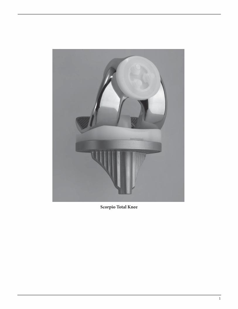
Scorpio Total Knee
1
Peter M. Bonutti, M.D. James A. D’Antonio, M.D. James W. Scott, M.D.Effingham, Illinois Sewickley, Pennsylvania Tift General Hospital Assistant Clinical Professor Clinical Assistant Professor of Tifton, Georgia university of Arkansas Orthopaedic SurgeryLittle Rock, Arkansas university of Pittsburgh Pittsburgh, Pennsylvania
Steven Zelicof, M.D., Ph.D.Assistant Professor of Orthopaedic SurgeryNew York Medical College Chief, Arthritis and Joint Reconstruction Service Westchester County Medical Center Valhalla, New York
EXPOSURE
Figure 1 Figure 2
Figure 3
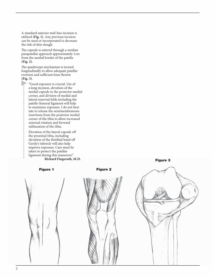
A standard anterior mid-line incision is utilized (Fig. 1). Any previous incision can be used or incorporated to decrease the risk of skin slough.The capsule is entered through a median parapatellar approach approximately 1cm from the medial border of the patella (Fig. 2).The quadriceps mechanism is incised longitudinally to allow adequate patellar eversion and sufficient knee flexion (Fig. 3).
“Good exposure is crucial. use of a long incision, elevation of the medial capsule to the posterior medial corner, and division of medial and lateral synovial folds including the patello-femoral ligament will help to maximize exposure. I do not hesi-tate to release the semimembranosis insertions from the posterior medial corner of the tibia to allow increased external rotation and forward subluxation of the tibia. Elevation of the lateral capsule off the proximal tibia, including elevation of the iliotibial band off Gerdy’s tubercle will also help improve exposure. Care must be taken to protect the patellar ligament during this maneuver.” Richard Fingeroth, M.D.
2

FEMORAL PREPARATION
Femoral Intramedullary Alignment
use a 3/8" diameter drill to enter the intramedullary canal of the femur (Fig. 4).The drill hole is located approximately 1cm anterior to the femoral attachment of the posterior cruciate ligament and slightly medial to the mid-line of the distal femur (Fig. 5).Identification of landmarks may be aided by removal of osteophytes from the margins of the intercondylar notch. It is recommended that the drill hole be slightly enlarged. This can be accomplished by toggling the drill, using a ronguer, or inserting an axial reamer.
“I utilize a short, T-Handle reamer which enlarges the hole to approximately 10mm, which is approximately 2mm larger in diameter than the fluted alignment guide rod. To help avoid fat emboli and pressurization of marrow contents, the femoral canal should be thoroughly irrigated and suctioned until the return suction is clear.”
Hugh Morris, M.D.“Slight posterior malposition of the drill hole is preferable to anterior malposition. The latter will cause the distal cut to be in extension, increasing the risk of the anterior femoral cut violating the anterior femoral cortex.”
Richard Fingeroth, M.D.
Figure 4
Figure 5
3/8" Drill Hole
Femoral IM Hole Placement
3
Femoral IM Alignment
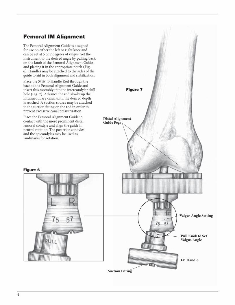
The Femoral Alignment Guide is designed for use on either the left or right knee and can be set at 5 or 7 degrees of valgus. Set the instrument to the desired angle by pulling back on the knob of the Femoral Alignment Guide and placing it in the appropriate notch (Fig. 6). Handles may be attached to the sides of the guide to aid in both alignment and stabilization.Place the 5/16" T-Handle Rod through the back of the Femoral Alignment Guide and insert this assembly into the intercondylar drill hole (Fig. 7). Advance the rod slowly up the intramedullary canal until the desired depth is reached. A suction source may be attached to the suction fitting on the rod in order to prevent excessive canal pressurization. Place the Femoral Alignment Guide in contact with the more prominent distal femoral condyle and align the guide in neutral rotation. The posterior condyles and the epicondyles may be used as landmarks for rotation.
Figure 6
Figure 7
Distal Alignment Guide Pegs
Valgus Angle Setting
Suction Fitting
IM Handle
Pull Knob to Set Valgus Angle
4
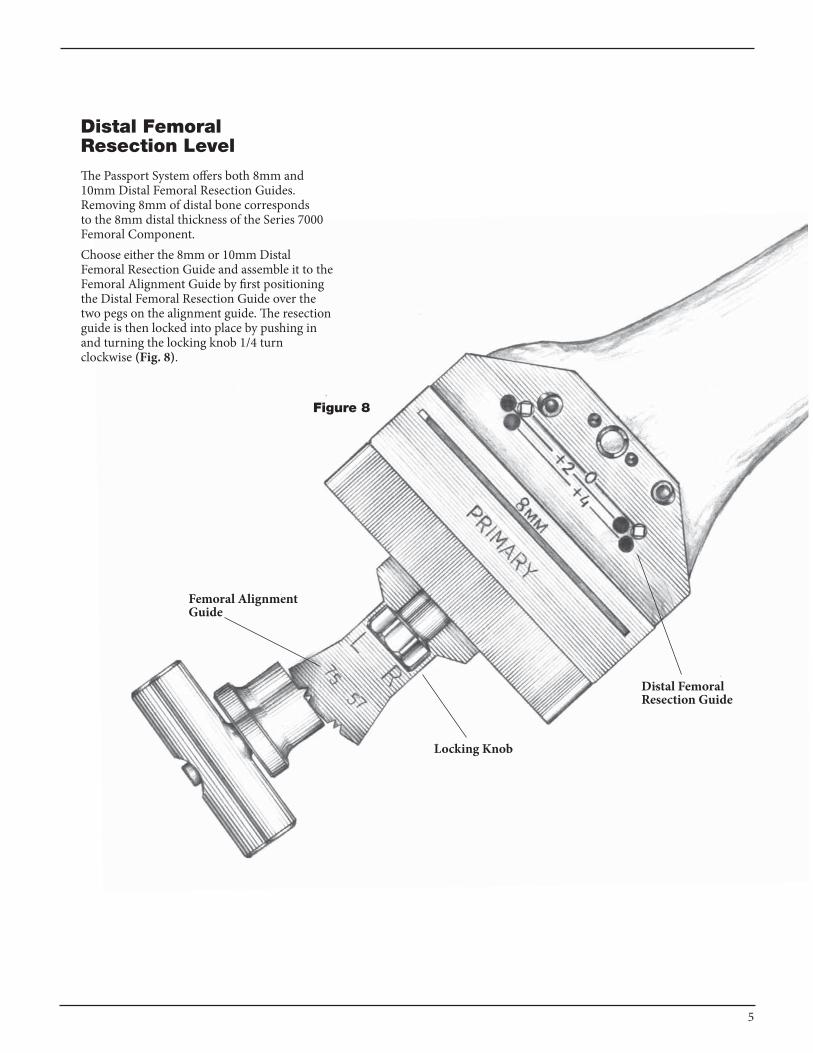
Distal Femoral Resection Level
The Passport System offers both 8mm and 10mm Distal Femoral Resection Guides. Removing 8mm of distal bone corresponds to the 8mm distal thickness of the Series 7000 Femoral Component.Choose either the 8mm or 10mm Distal Femoral Resection Guide and assemble it to the Femoral Alignment Guide by first positioning the Distal Femoral Resection Guide over the two pegs on the alignment guide. The resection guide is then locked into place by pushing in and turning the locking knob 1/4 turn clockwise (Fig. 8).
Femoral Alignment Guide
Figure 8
Distal Femoral Resection Guide
Locking Knob
5

Prior to pinning the Distal Femoral Resection Guide to the femur, an optional external alignment check may be performed. Attach the Alignment Handle to the Distal Femoral Resection Guide and insert an Alignment Rod into the handle (Fig. 9). Alignment is correct when the rod intersects the center of the femoral head and roughly parallels the axis of the femur in the lateral view. Once acceptable alignment is confirmed, remove the handle and pin the Distal Femoral Resection Guide to the anterior femur by using two 1/8" Drill-Pins.The Drill-Pin Driver can be attached di-rectly to a reamer, drill fitting, or a Jacob’s Chuck. The Drill-Pins are loaded into the driver and drilled through the “0” set of holes on the resection guide. The pins are automatically released from the driver as it is pulled back.After the resection guide is pinned in place, the alignment guide is removed. First release the resection guide from the alignment guide by pushing in and rotating the locking knob 1/4 turn counter-clockwise. Remove the IM rod, and then the Distal Femoral Alignment Guide, leaving the Distal Femoral Resection Guide in place (Fig. 10).At this point, the level of distal femoral resection may be altered by repositioning the resection guide in either the +2mm or +4mm holes. This will resect an additional 2mm or 4mm of bone respectively.Pinning through the “x” Pin hole will aid in further securing the guide.Note: If the “x” Pin hole is used, this pin must be removed prior to repositioning or removing the Distal Femoral Resection Guide.Note: A Stryker Blade Runner may be used to further assess the resection.Note: The components shall be positioned to avoid excessive hyperextension. Excessive Femoral flexion and tibial slope should be avoided when implanting the components. Implant positioning resulting in excessive hyperexternsion may result in premature wear and damage to the implant.
Figure 9
Figure 10
Alignment Rod
Alignment Handle
“X” Pin Holes
6

Figure 11
Distal Femoral Resection
Once the resection level is determined, the distal femoral resection is made (Fig. 11).Stryker Passport Instruments are designed to provide precise control of the sawblade during bone resections. use of a .050" (1.27mm) thick saw blade will result in the most accurate resections. Once the distal femoral resection is complete, the guide is removed and the resection is checked for flatness.Remove the 1/8" Drill-Pins with the Pin Puller.Once the distal femoral resection is completed, it should be checked for flatness.
Distal FemoralResection Guide
1/8" Drill-Pins
7

Femoral A/P Sizing
Assemble the pre-determined size Femoral A/P Sizing Guide and Femoral A/P Sizing Stylus, setting the stylus length to match the corresponding sizing guide.Position the assembly flush on the flat distal femur, sliding the feet of the sizing guide under the posterior condyles. The stylus point should be placed just lateral to the trochlear groove of the anterior cortex. It is important that the stylus point rest on bone and not soft tissue (Fig. 12).The size is determined by the position of the scribe mark on the stylus shaft within the sizing window located on the face of the sizing guide. When the scribe mark falls between the “up” and “down” positions, that size is confirmed (Fig. 13). Also, the width of the sizing guide is identical to that of the corresponding size femoral component and may also be used to further confirm accurate sizing.If the scribe mark lies on or above the “up” line, the next larger size Femoral A/P Sizing Guide is chosen and the sizing procedure is repeated. If the scribe mark lies on or below the “down” line, the next smaller Femoral A/P Sizing Guide is chosen and the sizing procedure is repeated. It is recommended that the anterior resection level is checked to further confirm the correct size by sliding a Stryker Blade Runner through the sizing guide’s anterior slots and assessing the eventual resection.
Figure 12
Set Stylus to Corresponding Size
Femoral A/P Sizing Guide
Anterior Slot
Detail of Sizing WindowFigure 13
8

Alternate Sizing Methods
For the situation where the femur seems to be in-between sizes, an alternative approach may be taken. For example, if the size 9 Femoral A/P Sizing Guide appears to be too large, and the size 7 Femoral A/P Sizing Guide indicates a possible anterior notch, mark the fixation holes through the size 9 Femoral A/P Sizing Guide and use the size 7 Femoral Resection Guide to perform the resections. This method shifts the resection levels of the size 7 Femoral Resection Guide anteriorly approximately 2mm, resecting less anteriorly and more off the posterior condyles. It is extremely important to check the anterior resection level of the size 7 Femoral Resection Guide with a Blade Runner before making the resections.For special circumstances, the Femoral A/P Sizing Guides may be used in an anterior referencing manner. Select the appropriate Femoral A/P Sizing Guide based on pre-operative templating and approximation using a Trial Femoral Component. Assemble the Femoral A/P Sizing Stylus to the sizing guide and turn the point of the stylus in the opposite direction of the sizing guide’s posterior feet.
Once again, the stylus length should be set to the same size as the sizing guide being used. The stylus point will approximate the end point of the lateral flange of the same size femoral component.Align the scribe mark on the stylus’ shaft with the engraved line on the face of the Femoral A/P Sizing Guide (the same side with the posterior feet). Tighten the side screw to secure the stylus in position (Fig. 14). Place the sizing guide flush against the distal femur with the stylus point referencing the anterior cortex at a point just lateral to the trochlear groove. The stylus point now repre-sents the the level of the anterior resection.Mark the location for the corresponding size Femoral Resection Guide’s fixation lugs using the figure “8” holes on the face of the Femoral A/P Sizing Guide. Please Note: When using the Femoral A/P Sizing Guide to anterior reference the femoral resections, any external rotation must be based off the epicondyles and/or the anterior cortex. Also, the anterior resection slots may not be used to check the anterior resection level.
Align Scribe Marks
Stylus Facing Away from Feet
Figure 14
Femoral A/P Sizing Guide using Anterior Reference Method
Set Stylus to Corresponding Size
9
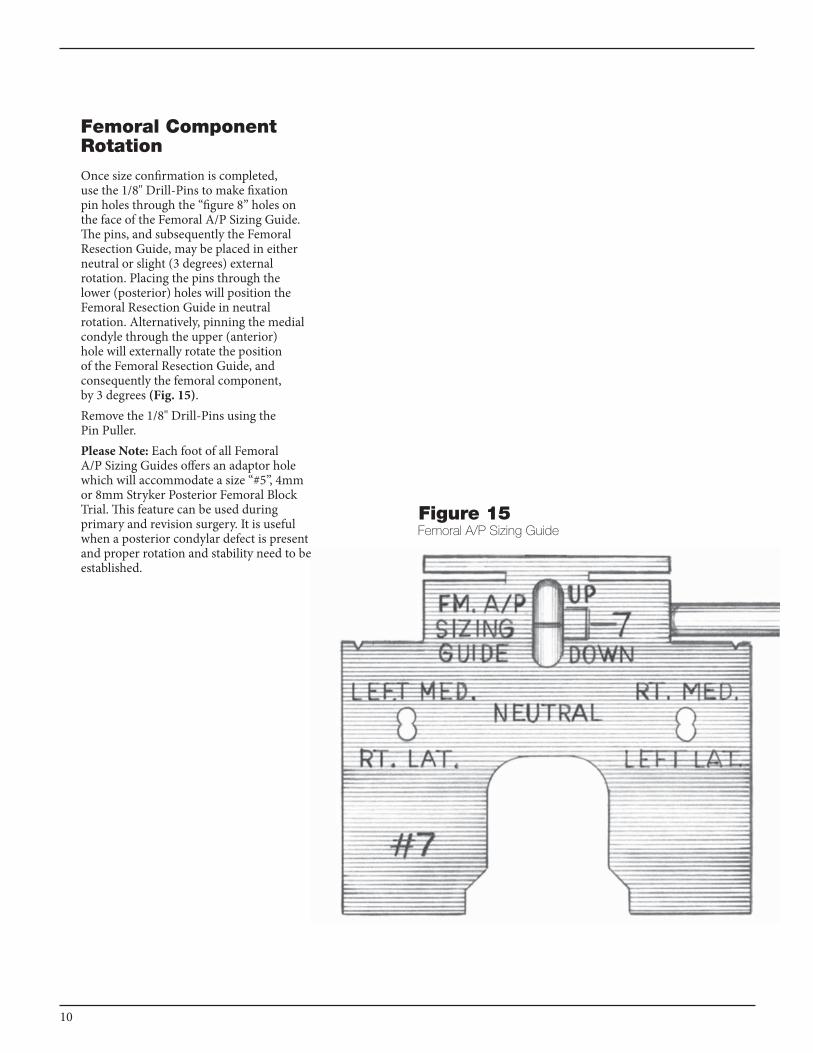
Femoral Component Rotation
Once size confirmation is completed, use the 1/8" Drill-Pins to make fixation pin holes through the “figure 8” holes on the face of the Femoral A/P Sizing Guide. The pins, and subsequently the Femoral Resection Guide, may be placed in either neutral or slight (3 degrees) external rotation. Placing the pins through the lower (posterior) holes will position the Femoral Resection Guide in neutral rotation. Alternatively, pinning the medial condyle through the upper (anterior) hole will externally rotate the position of the Femoral Resection Guide, and consequently the femoral component, by 3 degrees (Fig. 15). Remove the 1/8" Drill-Pins using the Pin Puller.Please Note: Each foot of all Femoral A/P Sizing Guides offers an adaptor hole which will accommodate a size “#5”, 4mm or 8mm Stryker Posterior Femoral Block Trial. This feature can be used during primary and revision surgery. It is useful when a posterior condylar defect is present and proper rotation and stability need to be established.
Femoral A/P Sizing GuideFigure 15
10
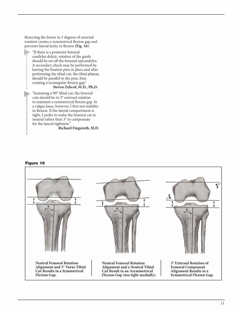
Neutral Femoral Rotation Alignment and 3° Varus Tibial Cut Results in a Symmetrical Flexion Gap.
Neutral Femoral Rotation Alignment and a Neutral Tibial Cut Result in an Asymmetrical Flexion Gap (too tight medially).
3° External Rotation of Femoral Component Alignment Results in a Symmetrical Flexion Gap.
Figure 16
Resecting the femur in 3 degrees of external rotation creates a symmetrical flexion gap and prevents lateral laxity in flexion (Fig. 16).
“If there is a posterior femoral condylar deficit, rotation of the guide should be set off the femoral epicondyles. A secondary check may be performed by leaving the fixation pins in place and after performing the tibial cut, the tibial plateau should be parallel to the pins, thus creating a rectangular flexion gap.” Steven Zelicof, M.D., Ph.D.“Assuming a 90° tibial cut, the femoral cuts should be in 3° external rotation to maintain a symmetrical flexion gap. In a valgus knee, however, I first test stability in flexion. If the lateral compartment is tight, I prefer to make the femoral cut in neutral rather than 3° to compensate for the lateral tightness.” Richard Fingeroth, M.D.
11
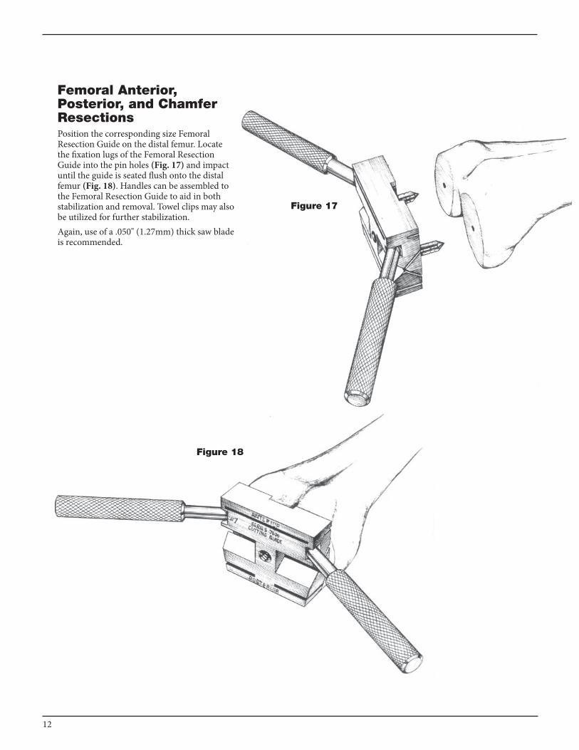
Femoral Anterior, Posterior, and Chamfer ResectionsPosition the corresponding size Femoral Resection Guide on the distal femur. Locate the fixation lugs of the Femoral Resection Guide into the pin holes (Fig. 17) and impact until the guide is seated flush onto the distal femur (Fig. 18). Handles can be assembled to the Femoral Resection Guide to aid in both stabilization and removal. Towel clips may also be utilized for further stabilization.Again, use of a .050" (1.27mm) thick saw blade is recommended.
Figure 18
Figure 17
12

Complete the remaining four femoral bone resections (Figs. 19, 20). The order of bone resections is not critical, however, a recommended sequence is: 1. anterior cortex; 2. posterior condyles; 3. posterior chamfer; 4. anterior chamfer.When performing the anterior chamfer resection, the sawblade should be passed over the mid-line of the femur so that the center portion of bone is resected. Care should be taken not to bias the blade while resecting the bone, as it will cause excess friction between the blade and Femoral Resection Guide.The Femoral Resection Guide is removed.
Anterior and Posterior Chamfer Resections
Figure 20
Anterior and Posterior Resections
Figure 19
13
“Care must be taken to protect the posterior cruciate ligament, as well as the collateral ligaments. These are especially at risk during the posterior condyle cuts. I use “Z” retractors medially and laterally with thin curved elevators or jokers in the notch.” Richard Fingeroth, M.D.
Scorpio UniversalNotch Block
Figure 21
14
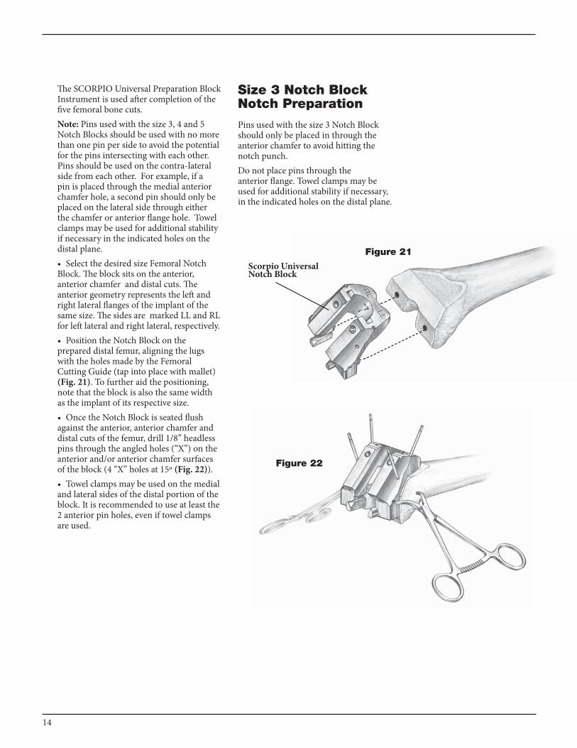
The SCORPIO universal Preparation Block Instrument is used after completion of the five femoral bone cuts.Note: Pins used with the size 3, 4 and 5 Notch Blocks should be used with no more than one pin per side to avoid the potential for the pins intersecting with each other. Pins should be used on the contra-lateral side from each other. For example, if a pin is placed through the medial anterior chamfer hole, a second pin should only be placed on the lateral side through either the chamfer or anterior flange hole. Towel clamps may be used for additional stability if necessary in the indicated holes on the distal plane.• Select the desired size Femoral Notch Block. The block sits on the anterior, anterior chamfer and distal cuts. The anterior geometry represents the left and right lateral flanges of the implant of the same size. The sides are marked LL and RL for left lateral and right lateral, respectively. • Position the Notch Block on the prepared distal femur, aligning the lugs with the holes made by the Femoral Cutting Guide (tap into place with mallet) (Fig. 21). To further aid the positioning, note that the block is also the same width as the implant of its respective size. • Once the Notch Block is seated flush against the anterior, anterior chamfer and distal cuts of the femur, drill 1/8” headless pins through the angled holes (“x”) on the anterior and/or anterior chamfer surfaces of the block (4 “x” holes at 15º (Fig. 22)).• Towel clamps may be used on the medial and lateral sides of the distal portion of the block. It is recommended to use at least the 2 anterior pin holes, even if towel clamps are used.
Size 3 Notch Block Notch PreparationPins used with the size 3 Notch Block should only be placed in through the anterior chamfer to avoid hitting the notch punch.Do not place pins through the anterior flange. Towel clamps may be used for additional stability if necessary, in the indicated holes on the distal plane.
Figure 22
SCORPIO® UNIVERSAL PREPARATION BLOCK
15
For Posterior Stabilized Knees
Choose one of the following options to prepare the femoral notch:
Notch Preparation Option 1:Punch Technique
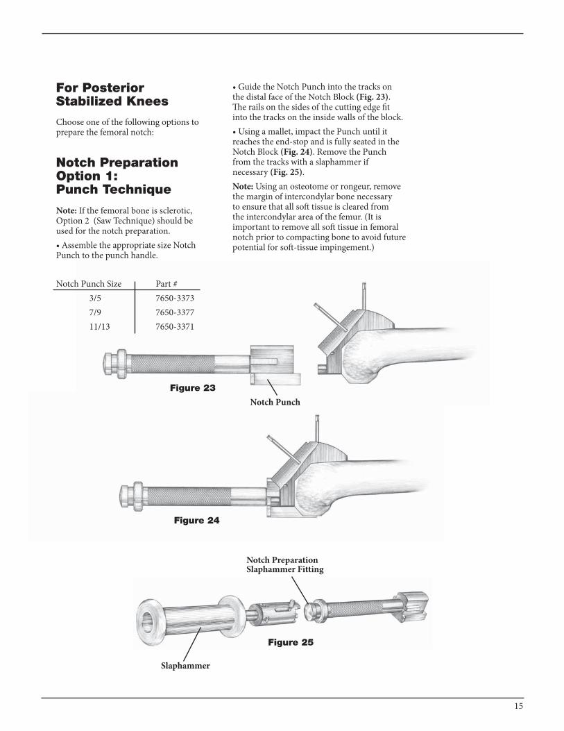
Note: If the femoral bone is sclerotic, Option 2 (Saw Technique) should be used for the notch preparation.• Assemble the appropriate size Notch Punch to the punch handle.
Notch Punch Size Part # 3/5 7650-3373 7/9 7650-3377 11/13 7650-3371
• Guide the Notch Punch into the tracks on the distal face of the Notch Block (Fig. 23). The rails on the sides of the cutting edge fit into the tracks on the inside walls of the block. • Using a mallet, impact the Punch until it reaches the end-stop and is fully seated in the Notch Block (Fig. 24). Remove the Punch from the tracks with a slaphammer if necessary (Fig. 25).Note: using an osteotome or rongeur, remove the margin of intercondylar bone necessary to ensure that all soft tissue is cleared from the intercondylar area of the femur. (It is important to remove all soft tissue in femoral notch prior to compacting bone to avoid future potential for soft-tissue impingement.)
Figure 23
Notch Punch
Figure 24
Notch PreparationSlaphammer Fitting
Figure 25
Slaphammer

16
Notch Preparation Option 2: Saw Technique
• Guide the pegs of the modular Notch Saw Guide into the anterior holes on the Notch Block (Fig. 26).• Use a narrow saw blade, osteotome, or double-edged reciprocating saw blade and the Notch Saw Guide as a guide to saw or cut distally through the entire depth of the intercondylar notch (Fig. 27).• Using the inner walls of the Universal Notch Guide as a saw guide, lay the saw blade flat against the cutting guide and saw on it through the intercondylar notch both medially and laterally until the cut is complete (Fig. 28).Note: Even if the saw technique is used, you must still perform the Notch Compacting step to confirm that enough bone was removed to accommodate for the cam and post.
Figure 26
Figure 27
Figure 28
17
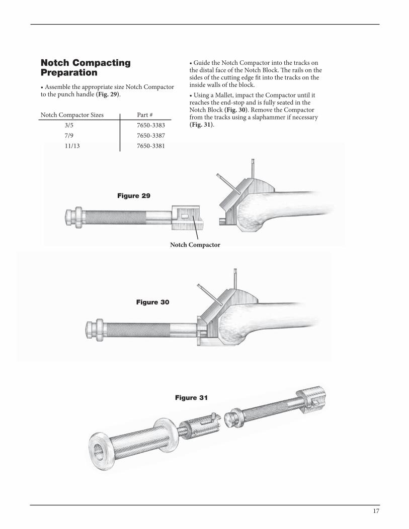
Notch Compacting Preparation• Assemble the appropriate size Notch Compactor to the punch handle (Fig. 29).
Notch Compactor Sizes Part # 3/5 7650-3383 7/9 7650-3387 11/13 7650-3381
• Guide the Notch Compactor into the tracks on the distal face of the Notch Block. The rails on the sides of the cutting edge fit into the tracks on the inside walls of the block.• Using a Mallet, impact the Compactor until it reaches the end-stop and is fully seated in the Notch Block (Fig. 30). Remove the Compactor from the tracks using a slaphammer if necessary (Fig. 31).
Figure 29
Notch Compactor
Figure 30
Figure 31
18
For Posterior Stabilized and Cruciate Retaining Knees
Choose one of the following options to prepare the patella recess:
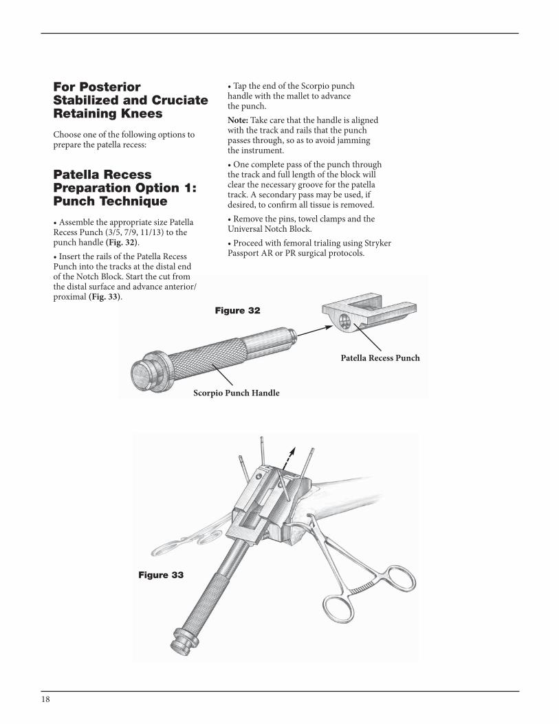
Patella Recess Preparation Option 1: Punch Technique
• Assemble the appropriate size Patella Recess Punch (3/5, 7/9, 11/13) to the punch handle (Fig. 32).• Insert the rails of the Patella Recess Punch into the tracks at the distal end of the Notch Block. Start the cut from the distal surface and advance anterior/proximal (Fig. 33).
• Tap the end of the Scorpio punch handle with the mallet to advance the punch. Note: Take care that the handle is aligned with the track and rails that the punch passes through, so as to avoid jamming the instrument. • One complete pass of the punch through the track and full length of the block will clear the necessary groove for the patella track. A secondary pass may be used, if desired, to confirm all tissue is removed. • Remove the pins, towel clamps and the universal Notch Block.• Proceed with femoral trialing using Stryker Passport AR or PR surgical protocols.
Patella Recess Punch
Figure 32
Scorpio Punch Handle
Figure 33

19
Patella Recess Preparation Option 2: Rasp Technique
• Assemble the Scorpio punch handle to the appropriate size rasp (3/5, 7/9, 11/13)(Fig. 34).• Start from the distal surface and advance to anterior/proximal so the entire rasp passes through the length of the block. The position of the rasp is constrained within the block.• Continue cutting with the rasp until it rides flat on the top surface of the block. The groove is then completely prepared (Fig. 35).
Note: The rasp only cuts in one direction.• Remove the pins, towel clamps and the universal Notch Block.
Scorpio Rasp
Scorpio Handle
Figure 35
Figure 34
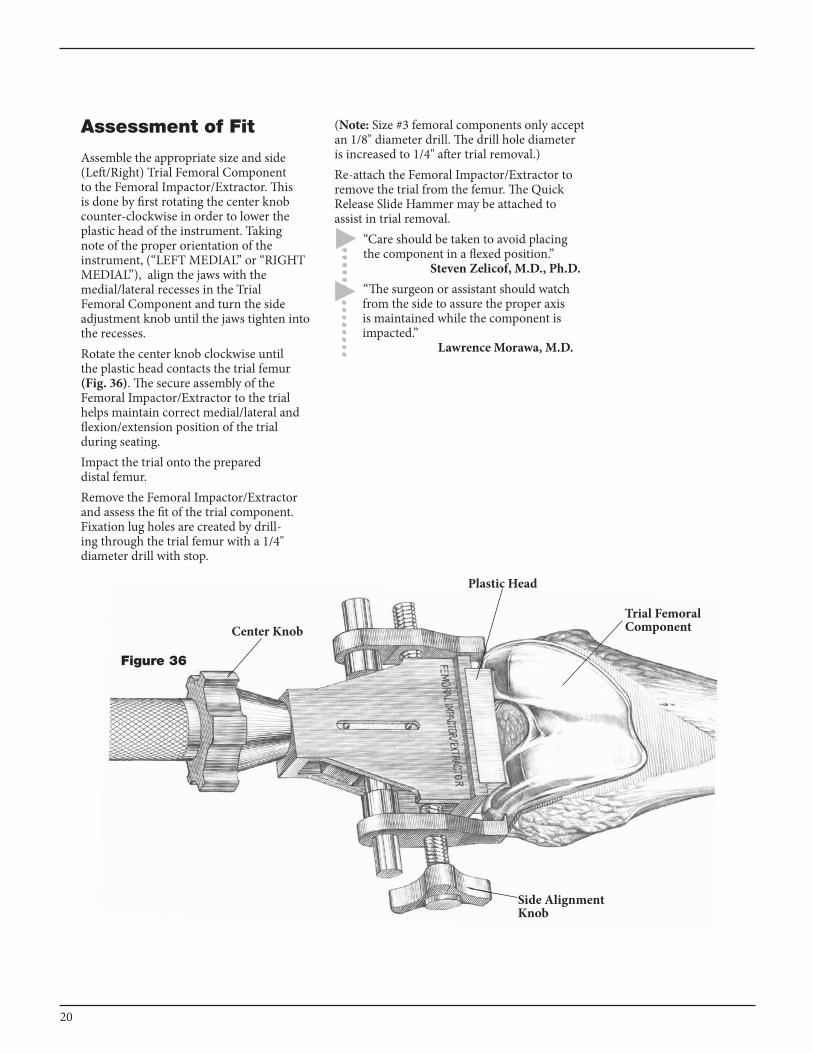
Assessment of Fit
Assemble the appropriate size and side (Left/Right) Trial Femoral Component to the Femoral Impactor/Extractor. This is done by first rotating the center knob counter-clockwise in order to lower the plastic head of the instrument. Taking note of the proper orientation of the instrument, (“LEFT MEDIAL” or “RIGHT MEDIAL”), align the jaws with the medial/lateral recesses in the Trial Femoral Component and turn the side adjustment knob until the jaws tighten into the recesses. Rotate the center knob clockwise until the plastic head contacts the trial femur (Fig. 36). The secure assembly of the Femoral Impactor/Extractor to the trial helps maintain correct medial/lateral and flexion/extension position of the trial during seating.Impact the trial onto the prepared distal femur.Remove the Femoral Impactor/Extractor and assess the fit of the trial component. Fixation lug holes are created by drill-ing through the trial femur with a 1/4" diameter drill with stop.
Center Knob
Side Alignment Knob
Figure 36
Plastic Head
Trial Femoral Component
(Note: Size #3 femoral components only accept an 1/8" diameter drill. The drill hole diameter is increased to 1/4" after trial removal.)Re-attach the Femoral Impactor/Extractor to remove the trial from the femur. The Quick Release Slide Hammer may be attached to assist in trial removal.
“Care should be taken to avoid placing the component in a flexed position.” Steven Zelicof, M.D., Ph.D.“The surgeon or assistant should watch from the side to assure the proper axis is maintained while the component is impacted.”
Lawrence Morawa, M.D.
20

TIBIAL PREPARATION
Tibial External Alignment Option
With the knee flexed, place the External Tibial Alignment Guide on the tibial shaft. Place the spring-loaded clamp around the distal tibia just above the malleoli. Place the head of the instrument over the tibial eminence. There should be a finger’s breadth clearance between the proximal shaft of the alignment guide and the anterior cortex when the head is positioned properly. Center the proximal fixation pins over the tibial eminence and tap in the most posterior pin first to fix the A/P location of the head. Rotation is now adjusted, and then set, by anchoring the second pin. Tighten the vertical screw to secure the proximal shaft of the guide (Fig. 37).
Fixation PinProximal Shaft
Vertical Screw
Figure 37
21
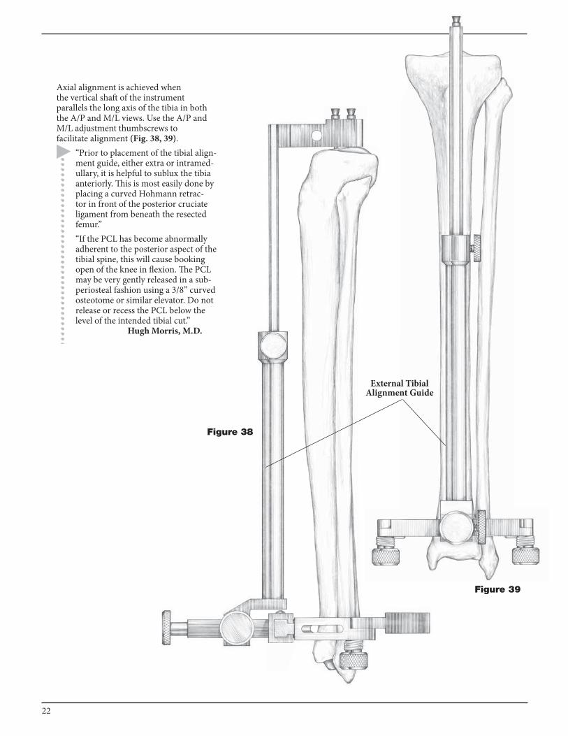
Axial alignment is achieved when the vertical shaft of the instrument parallels the long axis of the tibia in both the A/P and M/L views. use the A/P and M/L adjustment thumbscrews to facilitate alignment (Fig. 38, 39).
“Prior to placement of the tibial align-ment guide, either extra or intramed-ullary, it is helpful to sublux the tibia anteriorly. This is most easily done by placing a curved Hohmann retrac-tor in front of the posterior cruciate ligament from beneath the resected femur.” “If the PCL has become abnormally adherent to the posterior aspect of the tibial spine, this will cause booking open of the knee in flexion. The PCL may be very gently released in a sub-periosteal fashion using a 3/8” curved osteotome or similar elevator. Do not release or recess the PCL below the level of the intended tibial cut.” Hugh Morris, M.D.
External Tibial Alignment Guide
Figure 38
Figure 39
22

Landmarks often used to obtain correct axial alignment and rotation include: 1. Tibial Tubercle - The alignment rod usually lies over the medial third of the tibial tubercle. 2. Second Metatarsal - The second metatarsal generally is in line with the center of the ankle (Fig. 40). 3. Intra-malleolar Axis - An 1/8" drill bit may be passed through the most distal portion of the alignment guide. When the drill bit is parallel to the axis of the malleoli, rotation (Fig. 41).Once axial alignment is established, tighten the A/P and M/L adjustment thumbscrews.
Figure 41Figure 40
Distal Alignment Rotational Alignment
Intra-malleolar Axis
“By external rotation of the foot and anterior translation of the tibia, the tibial plateau can be subluxed into the field, enhancing visualization. Medial and lateral menisci are excised and posterior menisco-femoral ligaments are released.” Steven Zelicof, M.D., Ph.D.
23

Tibial Resection Level
The Passport System offers Right and Left, 0 and 5 degree Tibial Resection Guides.Note: 0 degrees of posterior slope is recommended for use with the Scorpio PS femoral components. 5 degrees of posterior slope is recommended for use with the Scorpio CR femoral components.Note: The components shall be positioned to avoid excessive hyperextension. Excessive Femoral flexion and tibial slope should be avoided when implanting the components. Implant positioning resulting in excessive hyperextension may result in premature wear and damage to the implant.The Tibial Stylus is assembled to the appropriate Tibial Resection Guide by depressing the button on the Tibial Stylus and then fully seating it in either the medial or lateral hole on the top of the resection guide. Release the button to lock the stylus in place (Fig. 42).
Assemble the Tibial Resection Guide/ Tibial Stylus assembly to the External Tibial Alignment Guide by sliding it over the top of the proximal shaft, adjusting the stylus to reference the desired point
on the tibial plateau (Fig. 42A).“The posterior inclination of the tibial resection may be adjusted slightly by moving the distal end of the alignment jig anteriorly.” James Scott, M.D.
Figure 42
Tibial Resection Guide
Tibial Stylus
Locking Button
24
External Tibial Alignment Guide
Figure 42A
External Tibial Alignment Guide
Tibial Resection Guide
Tibial Stylus
External Tibial Alignment Guide
Tibial Resection Guide
Tibial Stylus
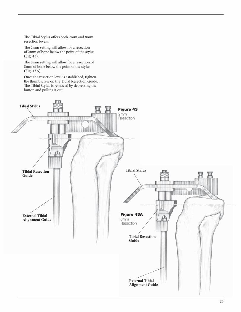
Figure 43A8mm Resection
The Tibial Stylus offers both 2mm and 8mm resection levels.The 2mm setting will allow for a resection of 2mm of bone below the point of the stylus (Fig. 43). The 8mm setting will allow for a resection of 8mm of bone below the point of the stylus (Fig. 43A).Once the resection level is established, tighten the thumbscrew on the Tibial Resection Guide. The Tibial Stylus is removed by depressing the button and pulling it out.
Figure 432mm Resection
25
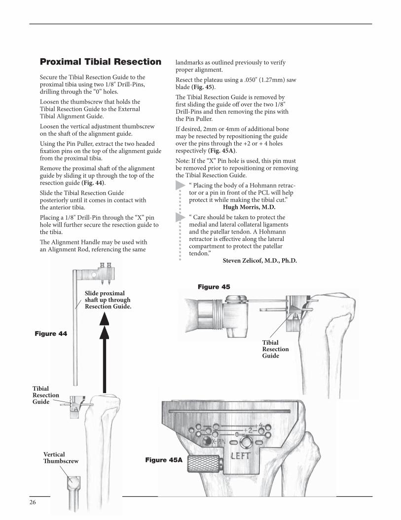
Proximal Tibial Resection
Secure the Tibial Resection Guide to the proximal tibia using two 1/8" Drill-Pins, drilling through the “0” holes.Loosen the thumbscrew that holds the Tibial Resection Guide to the External Tibial Alignment Guide.Loosen the vertical adjustment thumbscrew on the shaft of the alignment guide.using the Pin Puller, extract the two headed fixation pins on the top of the alignment guide from the proximal tibia.Remove the proximal shaft of the alignment guide by sliding it up through the top of the resection guide (Fig. 44).Slide the Tibial Resection Guide posteriorly until it comes in contact with the anterior tibia.Placing a 1/8" Drill-Pin through the “x” pin hole will further secure the resection guide to the tibia.The Alignment Handle may be used with an Alignment Rod, referencing the same
landmarks as outlined previously to verify proper alignment. Resect the plateau using a .050" (1.27mm) saw blade (Fig. 45).The Tibial Resection Guide is removed by first sliding the guide off over the two 1/8" Drill-Pins and then removing the pins with the Pin Puller.If desired, 2mm or 4mm of additional bone may be resected by repositioning the guide over the pins through the +2 or + 4 holes respectively (Fig. 45A).Note: If the “x” Pin hole is used, this pin must be removed prior to repositioning or removing the Tibial Resection Guide.
“ Placing the body of a Hohmann retrac-tor or a pin in front of the PCL will help protect it while making the tibial cut.” Hugh Morris, M.D.“ Care should be taken to protect the medial and lateral collateral ligaments and the patellar tendon. A Hohmann retractor is effective along the lateral compartment to protect the patellar tendon.” Steven Zelicof, M.D., Ph.D.
Figure 44
Tibial Resection Guide
Slide proximal shaft up through Resection Guide.
Figure 45
Tibial Resection Guide
Figure 45AVertical Thumbscrew
26

Tibial Intramedullary Alignment Option
Pre-op A/P and M/L x-rays of the tibial shaft should be obtained to determine the shape and size of the intramedullary canal. If the canal is excessively bowed or otherwise deformed (previous fracture, etc.) preventing proper placement of an IM rod, external alignment may be indicted.
Entry Hole and IM Rod Position
The Passport IM Tibial Alignment Instruments provide 1/4", 5/16", and 3/8" diameter cannulated IM Rods.If the tibial eminence is pronounced, make an initial cut to flatten the tibial plateau and expose an area of cancellous bone.Remove all soft tisssue, including remnants of the ACL, from the intercondylar area of the tibial plateau.Make an entry hole for access into the intramedullary canal using a 3/8" drill. It is generally agreed that a point on the tibial plateau approximately mid-line in the medio-lateral plane and at the approximate junction of the anterior and middle 1/3 of the plateau in the A/P plane will be in line with the tibial intramedullary canal (Fig. 46).The entry hole may also be prepared by utilizing the 3/8" Guide Bushing which has been assembled to the pre-determined size Tibial Trial Baseplate and positioned on the resected plateau (Fig. 46A).Proper alignment is confirmed by attaching the Alignment Handle and Alignment Rod to the Tibial Trial Baseplate so that the rod is parallel to the tibial axis in both the M/L and A/P planes.use a 3/8" diameter drill bit to create the entry hole. Advance the 3/8" drill bit only so far enough to gain access to the IM canal. Toggling the drill will create a slightly oversized hole which will aid in self-centering of the IM Rod and will allow for extrusion of marrow and fat during rod placement.
Figure 46
Tibial Baseplate
Figure 46A
3/8" Guide Bushing
Alignment Handle
27
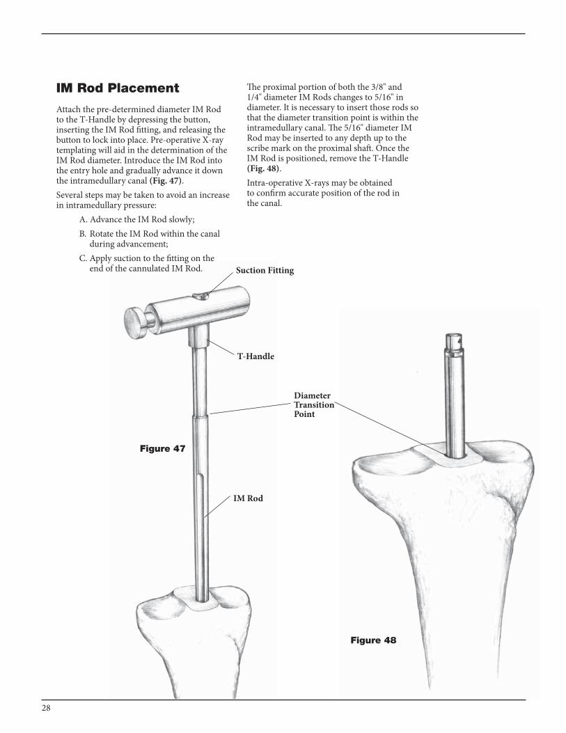
IM Rod Placement
Attach the pre-determined diameter IM Rod to the T-Handle by depressing the button, inserting the IM Rod fitting, and releasing the button to lock into place. Pre-operative x-ray templating will aid in the determination of the IM Rod diameter. Introduce the IM Rod into the entry hole and gradually advance it down the intramedullary canal (Fig. 47).Several steps may be taken to avoid an increase in intramedullary pressure: A. Advance the IM Rod slowly; B. Rotate the IM Rod within the canal during advancement; C. Apply suction to the fitting on the end of the cannulated IM Rod.
Figure 48
The proximal portion of both the 3/8" and 1/4" diameter IM Rods changes to 5/16" in diameter. It is necessary to insert those rods so that the diameter transition point is within the intramedullary canal. The 5/16" diameter IM Rod may be inserted to any depth up to the scribe mark on the proximal shaft. Once the IM Rod is positioned, remove the T-Handle (Fig. 48).Intra-operative x-rays may be obtained to confirm accurate position of the rod in the canal.
T-Handle
Diameter Transition Point
Figure 47
Suction Fitting
IM Rod
28
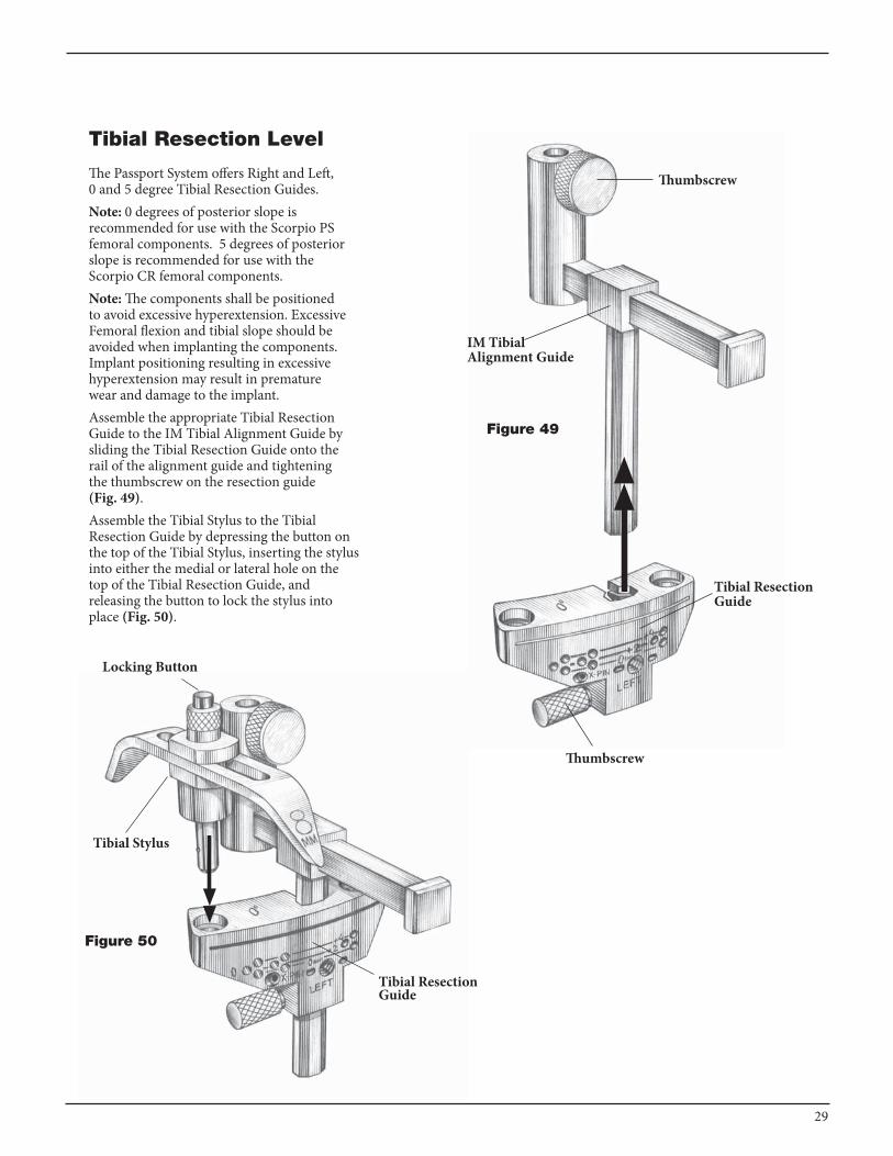
Figure 50
Locking Button
Tibial Stylus
Tibial Resection Guide
Tibial Resection Level
The Passport System offers Right and Left, 0 and 5 degree Tibial Resection Guides.Note: 0 degrees of posterior slope is recommended for use with the Scorpio PS femoral components. 5 degrees of posterior slope is recommended for use with the Scorpio CR femoral components.Note: The components shall be positioned to avoid excessive hyperextension. Excessive Femoral flexion and tibial slope should be avoided when implanting the components. Implant positioning resulting in excessive hyperextension may result in premature wear and damage to the implant.Assemble the appropriate Tibial Resection Guide to the IM Tibial Alignment Guide by sliding the Tibial Resection Guide onto the rail of the alignment guide and tightening the thumbscrew on the resection guide (Fig. 49).Assemble the Tibial Stylus to the Tibial Resection Guide by depressing the button on the top of the Tibial Stylus, inserting the stylus into either the medial or lateral hole on the top of the Tibial Resection Guide, and releasing the button to lock the stylus into place (Fig. 50).
Figure 49
Tibial Resection Guide
Thumbscrew
Thumbscrew
IM Tibial Alignment Guide
29

Slide the assembly over the Tibial IM Rod, positioning the Tibial Stylus to reference the desired point on the tibial plateau. Secure the IM Tibial Alignment Guide to the Tibial IM Rod by tightening the thumbscrew. Slide the Tibial Resection Guide posteriorly until it comes in contact with the anterior tibia. Further adjustments to the resection level may be made by loosening the thumbscrew on the Tibial Resection Guide and positioning it accordingly.The Tibial Stylus offers both 2mm and 8mm resection levels.The 2mm option will allow for a resection of 2mm of bone below the point of the stylus (Fig. 51). The 8mm option will allow for a resection of 8mm of bone below the point of the stylus (Fig. 51A).
Thumbscrew
Tibial Resection Guide
Thumbscrew
IM Tibial Alignment Guide Tibial Stylus
Thumbscrew
Tibial Resection Guide
Thumbscrew
IM TibialAlignment Guide
Tibial Stylus
Figure 512mm Resection Level
Figure 51A8mm Resection Level
30

Both the 0 and 5 degree Tibial Resection Guides may be used with the IM Tibial Alignment Guide. When the 0 degree Tibial Resection Guide is used, the A/P direction of the guide is not critical. However, when the 5 degree Tibial Resection Guide is used, care must be taken to direct the resection directly from anterior to posterior. Any mal-rotation of the resection may result in an inadvertent varus or valgus plane of resection.Accurate rotational position of the Tibial Resection Guide may be assessed by attaching the Alignment Handle to the front of the resection guide and inserting an Alignment Rod through the handle (Fig. 52).Several alignment references may be used to determine correct rotational position: A. The external rod will usually lie over the medial third of the tibial tubercle. B. The external rod should intersect the center of the talus, slightly medial to the mid-intermalleolar space. C. The external rod should be in line with the second metatarsal (provided no foot or lower leg abnormalities exist) (Fig. 53).
Figure 53
Figure 52
Alignment Handle
Alignment Rod
31
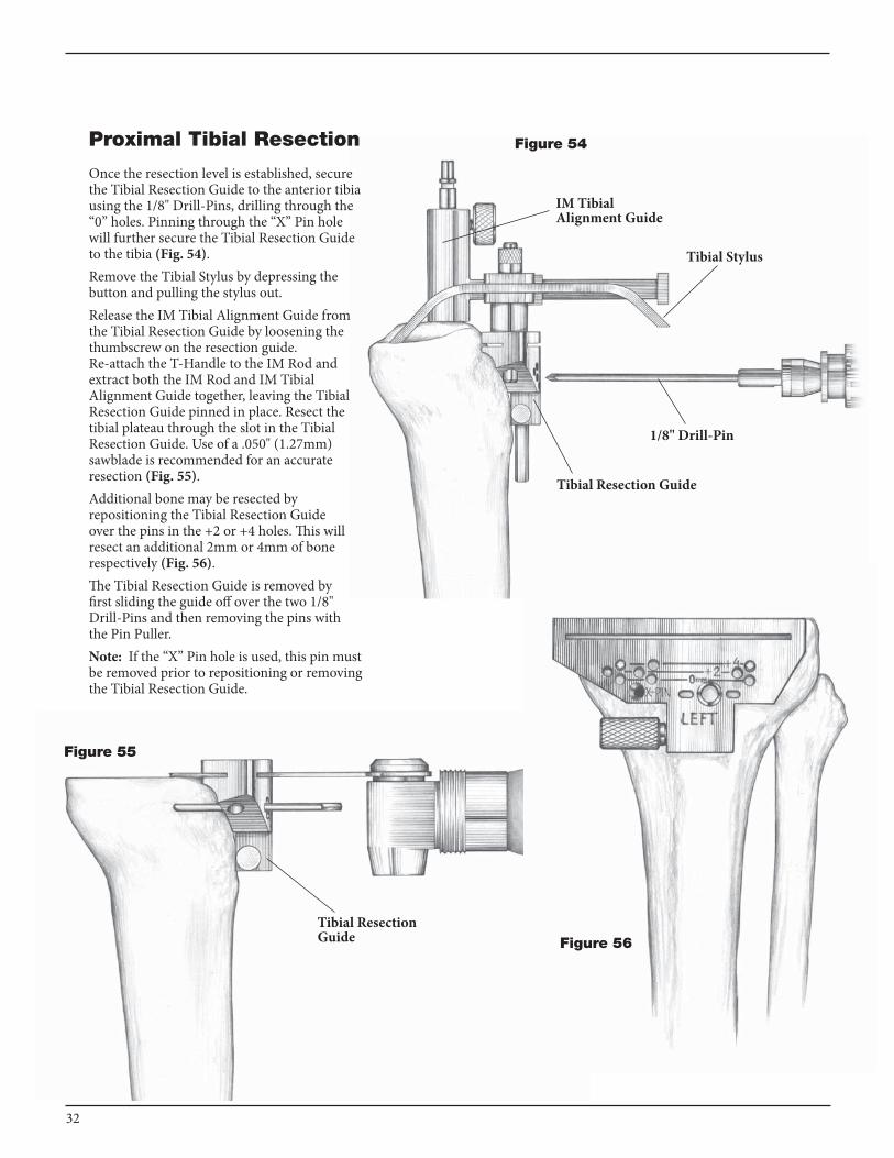
Proximal Tibial Resection
Once the resection level is established, secure the Tibial Resection Guide to the anterior tibia using the 1/8" Drill-Pins, drilling through the “0” holes. Pinning through the “x” Pin hole will further secure the Tibial Resection Guide to the tibia (Fig. 54).Remove the Tibial Stylus by depressing the button and pulling the stylus out.Release the IM Tibial Alignment Guide from the Tibial Resection Guide by loosening the thumbscrew on the resection guide. Re-attach the T-Handle to the IM Rod and extract both the IM Rod and IM Tibial Alignment Guide together, leaving the Tibial Resection Guide pinned in place. Resect the tibial plateau through the slot in the Tibial Resection Guide. use of a .050" (1.27mm) sawblade is recommended for an accurate resection (Fig. 55).Additional bone may be resected by repositioning the Tibial Resection Guide over the pins in the +2 or +4 holes. This will resect an additional 2mm or 4mm of bone respectively (Fig. 56).The Tibial Resection Guide is removed by first sliding the guide off over the two 1/8" Drill-Pins and then removing the pins with the Pin Puller.Note: If the “x” Pin hole is used, this pin must be removed prior to repositioning or removing the Tibial Resection Guide.
Figure 55
1/8" Drill-Pin
Tibial Resection Guide
Tibial Resection Guide
Tibial Stylus
IM Tibial Alignment Guide
Figure 54
Figure 56
32

Tibial Component Sizing
Maximally flex the knee and deliver the tibia forward.
“ To facilitate exposure of the tibial plateau, a limited release may be performed and extended as required to compensate for angular deformities. Medial osteophytes are removed to facilitate the medial release. The lateral fat pad is freed from the infrapatellar bursa to allow superior lateral visualization.”
Steven Zelicof, M.D., Ph.D.Assemble a Tibial Trial Baseplate to the Align-ment Handle and place it on the resected tibial plateau (Fig. 57). Choose the size that best covers the tibial plateau. Slight overhang is preferable to undersizing.
“If slight medial or lateral overhang is necessary for adequate anterior- posterior cover, the overhang will be bet-ter tolerated laterally rather than medially. Medial overhang is associated with pain secondary to soft tissue impingement on the tray.” Richard Fingeroth, M.D.
Figure 57
DELTAFIT KEEL PREPARATION
33

Tibial Component Alignment
Replace the Trial Femoral Component on the femur. Assemble a Tibial Bearing Insert Trial to the Tibial Trial Baseplate by first positioning it posteriorly on the baseplate and then fully seating it anteriorly (Fig. 58). Reverse the steps to dis-assemble the insert trial from the baseplate.Position the assembled insert and baseplate on the tibial plateau and carry out a trial reduction. Assess overall component fit, ligament stability, and joint range of motion.As the joint is taken through flexion and extension, the femoral trial component helps position the tibial baseplate. Final position of the tibial trial is achieved when tibiofemoral articular contact is most congruent. This is best assessed when the knee is in extension.
“It is important to note that when taking the knee through range of motion, the patella should be in its normal position. If the knee is ranged while the patella is everted, it will abnormally externally rotate the tibia and give a false impression of the correct rotational orientation for the tibial baseplate.” Hugh Morris, M.D.“With the patella reduced, soft tissue balancing can also be evaluated at this time. If there is excessive tightness on one side, the tibial tray will lift off on the contralateral side as the knee is flexed and extended. Appropriate releases can then be performed until the tray remains flat through a full range of motion. Furthermore, if the PCL is too tight, the anterior tray will lift up as the knee is flexed. This can be corrected with PCL recession.” Richard Fingeroth, M.D.
Figure 58
34
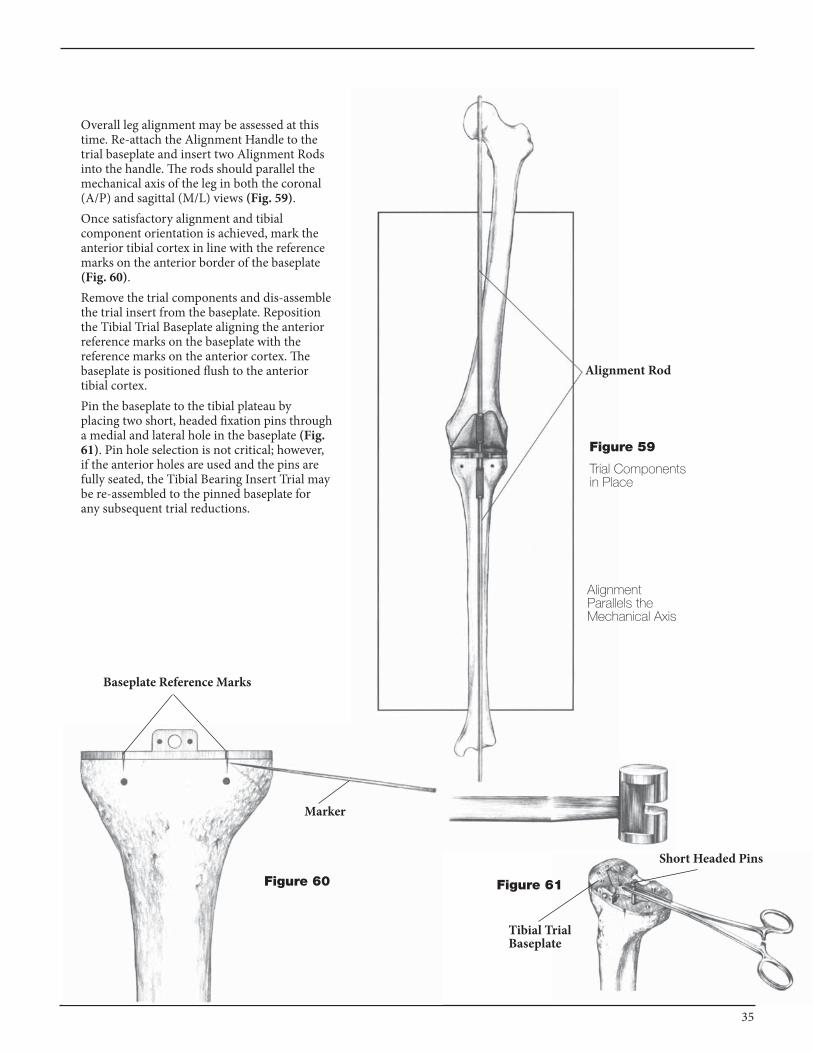
Overall leg alignment may be assessed at this time. Re-attach the Alignment Handle to the trial baseplate and insert two Alignment Rods into the handle. The rods should parallel the mechanical axis of the leg in both the coronal (A/P) and sagittal (M/L) views (Fig. 59).Once satisfactory alignment and tibial component orientation is achieved, mark the anterior tibial cortex in line with the reference marks on the anterior border of the baseplate (Fig. 60).Remove the trial components and dis-assemble the trial insert from the baseplate. Reposition the Tibial Trial Baseplate aligning the anterior reference marks on the baseplate with the reference marks on the anterior cortex. The baseplate is positioned flush to the anterior tibial cortex.Pin the baseplate to the tibial plateau by placing two short, headed fixation pins through a medial and lateral hole in the baseplate (Fig. 61). Pin hole selection is not critical; however, if the anterior holes are used and the pins are fully seated, the Tibial Bearing Insert Trial may be re-assembled to the pinned baseplate for any subsequent trial reductions.
Figure 60
Baseplate Reference Marks
Marker
Figure 61
Tibial Trial Baseplate
Short Headed Pins
Alignment Parallels the Mechanical Axis
Trial Components in Place
Figure 59
Alignment Rod
35
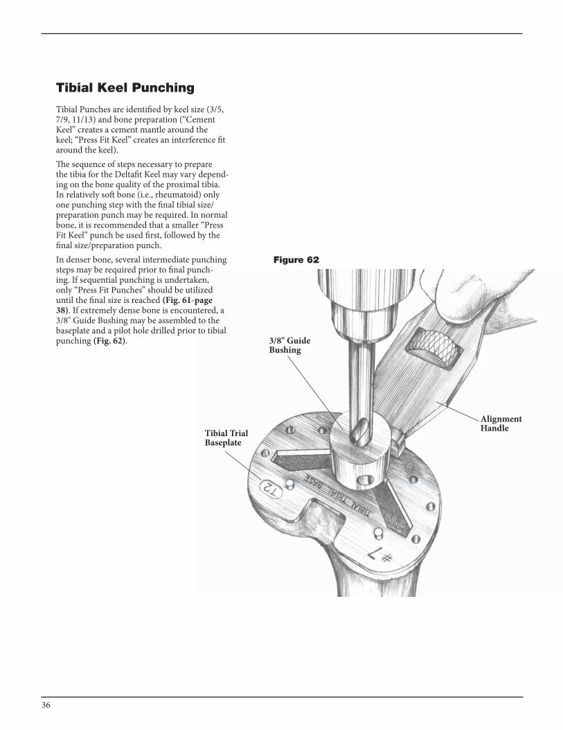
Tibial Keel Punching
Tibial Punches are identified by keel size (3/5, 7/9, 11/13) and bone preparation (“Cement Keel” creates a cement mantle around the keel; “Press Fit Keel” creates an interference fit around the keel).The sequence of steps necessary to prepare the tibia for the Deltafit Keel may vary depend-ing on the bone quality of the proximal tibia. In relatively soft bone (i.e., rheumatoid) only one punching step with the final tibial size/preparation punch may be required. In normal bone, it is recommended that a smaller “Press Fit Keel” punch be used first, followed by the final size/preparation punch.In denser bone, several intermediate punching steps may be required prior to final punch-ing. If sequential punching is undertaken, only “Press Fit Punches” should be utilized until the final size is reached (Fig. 61-page 38). If extremely dense bone is encountered, a 3/8" Guide Bushing may be assembled to the baseplate and a pilot hole drilled prior to tibial punching (Fig. 62).
Alignment Handle
3/8" Guide Bushing
Tibial Trial Baseplate
Figure 62
36
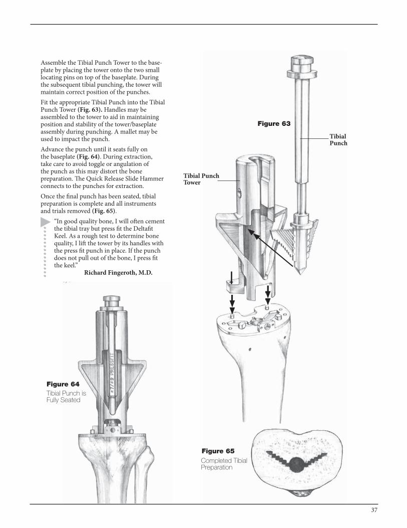
Assemble the Tibial Punch Tower to the base-plate by placing the tower onto the two small locating pins on top of the baseplate. During the subsequent tibial punching, the tower will maintain correct position of the punches.Fit the appropriate Tibial Punch into the Tibial Punch Tower (Fig. 63). Handles may be assembled to the tower to aid in maintaining position and stability of the tower/baseplate assembly during punching. A mallet may be used to impact the punch.Advance the punch until it seats fully on the baseplate (Fig. 64). During extraction, take care to avoid toggle or angulation of the punch as this may distort the bone preparation. The Quick Release Slide Hammer connects to the punches for extraction.Once the final punch has been seated, tibial preparation is complete and all instruments and trials removed (Fig. 65).
“In good quality bone, I will often cement the tibial tray but press fit the Deltafit Keel. As a rough test to determine bone quality, I lift the tower by its handles with the press fit punch in place. If the punch does not pull out of the bone, I press fit the keel.” Richard Fingeroth, M.D.
Figure 63
Figure 65Completed Tibial Preparation
Tibial Punch Tower
Tibial Punch
Figure 64Tibial Punch is Fully Seated
37
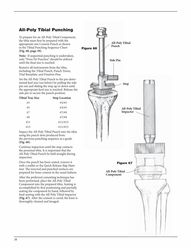
All-Poly Tibial Punching
To prepare for an All-Poly Tibial Component, the tibia must first be prepared with the appropriate size Cement Punch as shown in the Tibial Punching Sequence Chart (Fig. 68, page 39).Note: If sequential punching is undertaken, only “Press Fit Punches” should be utilized until the final size is reached. Remove all instruments from the tibia, including the Tibial Punch, Punch Tower, Trial Baseplate, and Fixation Pins.Set the All-Poly Tibial Punch to the pre-deter-mined keel size (see below) by pulling the side pin out and sliding the stop up or down until the appropriate keel size is reached. Release the side pin to secure the punch position.Tibial Tray Size Stop Location #3 #3/#5 #5 #3/#5 #7 #7/#9 #9 #7/#9 #11 #11/#13 #13 #11/#13Impact the All-Poly Tibial Punch into the tibia using the punch slots produced from the previous punching sequence as a guide (Fig. 66).Continue impaction until the stop contacts the proximal tibia. It is important that the All-Poly Tibial Punch be held straight during impaction.Once the punch has been seated, remove it with a mallet or the Quick Release Slap Ham-mer. The resected and punched surfaces are prepared for bone cement in the usual fashion.After the preferred cementing technique has been performed, place the All-Poly Tibial Component into the prepared tibia. Seating is accomplished by first positioning and partially seating the component by hand, followed by final seating with the All-Poly Tibial Impactor (Fig. 67). After the cement is cured, the knee is thoroughly cleaned and lavaged.
Figure 67
All-Poly Tibial Punch
Side Pin
Figure 66
Stop
All-Poly Tibial Impactor
All-Poly Tibial Component
38
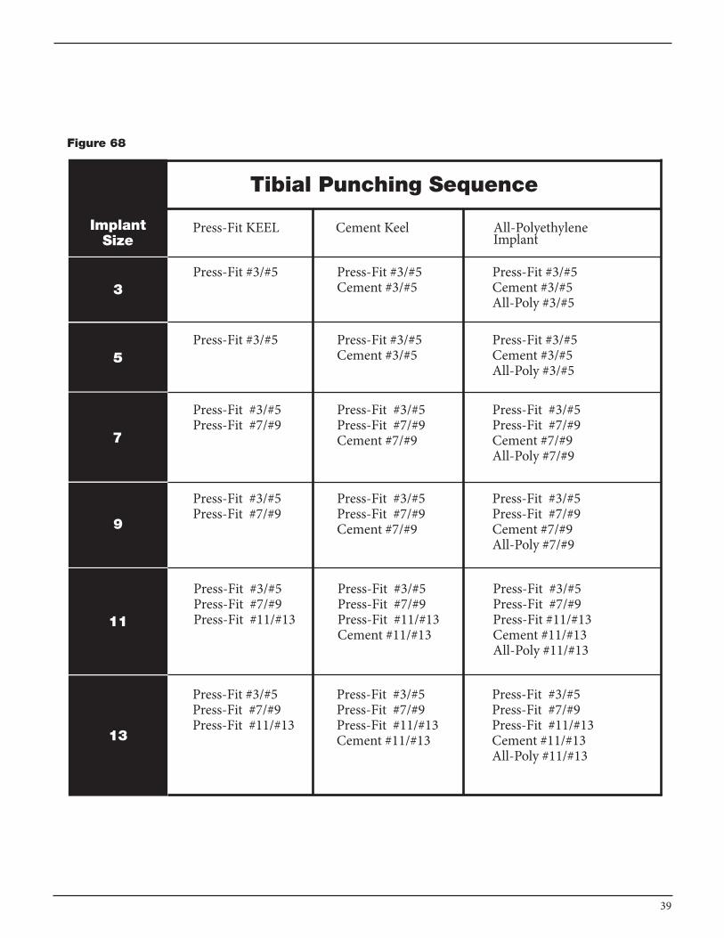
Figure 68
39
Tibial Punching Sequence
Press-Fit KEEL Cement Keel All-PolyethyleneImplant
Press-Fit #3/#5 Press-Fit #3/#5Cement #3/#5
Press-Fit #3/#5Cement #3/#5All-Poly #3/#5
Press-Fit #3/#5 Press-Fit #3/#5Cement #3/#5
Press-Fit #3/#5Cement #3/#5All-Poly #3/#5
Press-Fit #3/#5Press-Fit #7/#9
Press-Fit #3/#5Press-Fit #7/#9Cement #7/#9
Press-Fit #3/#5Press-Fit #7/#9Cement #7/#9All-Poly #7/#9
Press-Fit #3/#5Press-Fit #7/#9
Press-Fit #3/#5Press-Fit #7/#9Cement #7/#9
Press-Fit #3/#5Press-Fit #7/#9Cement #7/#9All-Poly #7/#9
Press-Fit #3/#5Press-Fit #7/#9Press-Fit #11/#13
Press-Fit #3/#5Press-Fit #7/#9Press-Fit #11/#13Cement #11/#13
Press-Fit #3/#5Press-Fit #7/#9Press-Fit #11/#13Cement #11/#13All-Poly #11/#13
Press-Fit #3/#5Press-Fit #7/#9Press-Fit #11/#13
Press-Fit #3/#5Press-Fit #7/#9Press-Fit #11/#13Cement #11/#13
Press-Fit #3/#5Press-Fit #7/#9Press-Fit #11/#13Cement #11/#13All-Poly #11/#13
ImplantSize
3
5
7
9
11
13
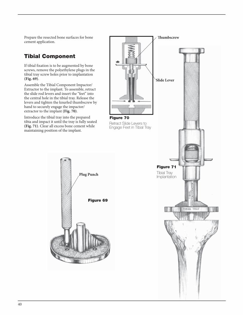
Prepare the resected bone surfaces for bone cement application.
Tibial Component
If tibial fixation is to be augmented by bone screws, remove the polyethylene plugs in the tibial tray screw holes prior to implantation (Fig. 69).Assemble the Tibial Component Impactor/ Extractor to the implant. To assemble, retract the slide rod levers and insert the “feet” into the central hole in the tibial tray. Release the levers and tighten the knurled thumbscrew by hand to securely engage the impactor/ extractor to the implant (Fig. 70).Introduce the tibial tray into the prepared tibia and impact it until the tray is fully seated (Fig. 71). Clear all excess bone cement while maintaining position of the implant.
Figure 70
Figure 69
Figure 71
COMPONENT IMPLANTATION
Thumbscrew
Slide Lever
Retract Slide Levers to Engage Feet in Tibial Tray
Tibial Tray Implantation
Plug Punch
40

Figure 72
First engage posteriorly, then snap into place anteriorly.
Tibial Bearing Insert
Tibial Bearing Insert Assembly
Prior to assembly of the prosthetic uHMWPE bearing insert, the trial insert may be placed in the tibial tray to once more assess joint stability and range of motion.To assemble the prosthetic bearing insert, distract the joint and angle the insert posteriorly into the tray. The posterior lips of the bearing insert must fit beneath the lips on the interior, posterior tray wall.
“Placement of the final polyethylene insert after hemostasis is obtained facilitates accessibility to posterior bleeding points and cement.”
Steven Zelicof, M.D., Ph.D.Then snap the insert in place anteriorly (Fig. 72). Hand pressure or a light tap with a mallet is required. The tibial bearing insert is fully seated once the metal retaining wire locks under the barbs on the anterior, interior surface of the tray wall. Be sure top surface of tray is free of cement, soft tissue or any other debris prior to assembling the insert.
Figure 73
Femoral Impactor/Extractor
41
Femoral Component
Assemble the appropriate size and side femoral implant to the Femoral Impactor/Extractor in the same manner as the femoral trial. Place the implant on the femur and impact it until fully seated (Fig. 73). The Impactor/Extractor aids in maintaining accurate position of the implant during implantation.
Note: The components shall be positioned to avoid excessive hyperextension. Excessive femoral flexion and tibial slope should be avoided when implanting the components. Implant positioning resulting in excessive hyperextension may result in premature wear and damage to the implant.
Closure
After cement polymerization, thoroughly irrigate the joint and place suction drains. Hemostasis is achieved after deflation of the tourniquet. Close soft tissues in the normal layered fashion.

CAUTION: FEDERAL LAW (u.S.A.) RESTRICTS THE STRYKER® TOTAL KNEE COMPONENTS TO SALE BY OR ON THE ORDER OF A LICENSED PHYSICIAN.
Warnings and Precautions:See package insert for warnings, precautions, adverse effects and other essential product information.
POSTOPERATIVE CARE, INDICATIONS, CONTRAINDICATIONS AND WARNINGS
Indications• Painful, disabling joint disease of the knee
resulting from: degenerative arthritis, rheumatoid arthritis or post-traumatic arthritis.
• Post-traumatic loss of knee joint configuration and function.
• Moderate varus, valgus, or flexion deformity in which the ligamentous structures can be returned to adequate function and stability.
• Revision of previous unsuccessful knee replacement or other procedure.
Additional Indications for Posteriorly Stabilized Components:• Ligamentous instability requiring implant
bearing surface geometries with increased constraint.
• Absent or non-functioning posterior cruciate ligament.
Indications for Bone Augmentation Wedges:• Painful, disabling joint disease of the
knee secondary to: degenerative arthritis, rheumatoid arthritis, or post-traumatic arthritis, complicated by the presence of bone loss.
• Salvage of previous unsuccessful total knee replacement or other surgical procedure, accompanied by bone loss.
Contraindications• Any active or suspected latent infection in or
about the knee joint.• Any mental or neuromuscular disorder
which would create an unacceptable risk of prosthesis instability, prosthesis fixation failure, or complications in post-operative care.
• Bone stock compromised by disease, infection or prior implantation which cannot provide adequate support and/or fixation to the prosthesis.
• Skeletal immaturity.• Severe instability of the knee joint
secondary to the absence of collateral ligament integrity and function.
• Obesity. An overweight or obese patient can produce loads on the prosthesis which can lead to failure of the fixation of the device or to failure of the device itself.
• Additional Contraindication for Bone Augmentation Wedges:
Bone stock which is sufficient for the adequate fixation of the total knee component without augmentation wedges.
42

43

A surgeon must always rely on his or her own professional clinical judgment when deciding whether to use a particular product when treating a particular patient. Stryker does not dispense medical advice and recommends that surgeons be trained in the use of any particular product before using it in surgery.
The information presented is intended to demonstrate the breadth of Stryker product offerings. A surgeon must always refer to the package insert, product label and/or instructions for use before using any Stryker product. Products may not be available in all markets because product availability is subject to the regulatory and/or medical practices in individual markets. Please contact your Stryker representative if you have questions about the availability of Stryker products in your area.
The products listed above are CE marked according to the Medical Device Directive 93/42/EEC. Products may not be available in all markets because product availability is subject to the regulatory and/or medical practices in individual markets. Please contact your Stryker representative if you have questions about the availability of Stryker products in your area.
Stryker Corporation or its divisions or other corporate affiliated entities own, use or have applied for the following trademarks or service marks: Passport, Scorpio, Stryker. All other trademarks are trademarks of their respective owners or holders.
Literature Number: LSPK20 Rev. 1MS/GS 11/11
Copyright © 2011 StrykerPrinted in uSA
325 Corporate DriveMahwah, NJ 07430t: 201 831 5000
www.stryker.com