passive survivability for single ... - university of...
TRANSCRIPT

1
PASSIVE SURVIVABILITY FOR SINGLE FAMILY HOME CONSTRUCTION IN FLORIDA
By
ANDREW JOSEPH MEJIA
A THESIS PRESENTED TO THE GRADUATE SCHOOL OF THE UNIVERSITY OF FLORIDA IN PARTIAL FULFILLMENT
OF THE REQUIREMENTS FOR THE DEGREE OF MASTER OF SCIENCE IN BUILDING CONSTRUCTION
UNIVERSITY OF FLORIDA
2008

2
© 2008 Andrew Joseph Mejia

3
To my family and friends.

4
ACKNOWLEDGMENTS
I would like to thank my parents and family first and foremost for their loving support. I
would also like to thank Dr. Kibert, for sparking my interest in sustainable design and
construction, along with Dr. Olbina and Dr. Grosskopf for their guidance while serving on my
supervisory committee. I would also like to thank Dr. Issa and Dottie Beaupied for all of their
time and assistance that they have offered to me.
5
TABLE OF CONTENTS page
ACKNOWLEDGMENTS ...............................................................................................................4
LIST OF FIGURES .........................................................................................................................7
ABSTRACT .....................................................................................................................................8
CHAPTER
1 INTRODUCTION ..................................................................................................................10
Introduction .............................................................................................................................10 Problem Statement ..................................................................................................................10 Research Objectives ................................................................................................................11 Scope and Limitations ............................................................................................................11
2 LITERATURE REVIEW .......................................................................................................13
Introduction .............................................................................................................................13 Heating ....................................................................................................................................13 Cooling ...................................................................................................................................14 Natural Ventilation .................................................................................................................16 Daylighting .............................................................................................................................18 Photovoltaic Power .................................................................................................................19 Rain Water Collection ............................................................................................................20
3 RESEARCH METHODOLOGY ...........................................................................................27
Introduction .............................................................................................................................27 Assumptions ...........................................................................................................................27 Creating a Model ....................................................................................................................27
4 RESULTS ...............................................................................................................................29
Heating and Cooling ...............................................................................................................29 Natural Ventilation .................................................................................................................30 Daylighting .............................................................................................................................31 Photovoltaic Solar Power Generation .....................................................................................32 Water .......................................................................................................................................34 Surviving in the Model Home ................................................................................................36
5 CONCLUSION .......................................................................................................................44
APPENDIX: PASSIVE SURVIVABILITY CHEKLIST .............................................................47

6
LIST OF REFERENCES ...............................................................................................................48
BIOGRAPHICAL SKETCH .........................................................................................................50

7
LIST OF FIGURES
Figure page 2-1 Sun’s path in summer and winter.......................................................................................22
2-2 Window overhang blocking sun radiation during summer months ...................................22
2-3 Window overhang allowing sun radiation during winter months ......................................23
2-4 Summer/winter tree performance ......................................................................................23
2-5 Use of tall plants to maximize breeze and provide shade ..................................................24
2-6 Stack effect ventilation ......................................................................................................24
2-7 Tube skylight .....................................................................................................................25
2-8 Thermal shade for clerestory windows ..............................................................................25
4-1 Orientation of model home ................................................................................................38
4-2 Sun elevation for May 1st & October 1st ............................................................................38
4-3 Layout of model home .......................................................................................................39
4-4 South elevation landscaping plan .......................................................................................39
4-5 West elevation landscaping plan ........................................................................................40
4-6 In-roof installation of PV array ..........................................................................................40
4-7 Output data for PV system .................................................................................................41
4-8 Self-cleaning gutter component .........................................................................................41
4-9 Floating extraction filter ....................................................................................................42
4-10 Riser diagram of rainwater delivery system ......................................................................42
4-11 Utility room ........................................................................................................................43

8
Abstract of Thesis Presented to the Graduate School Of the University of Florida in Partial Fulfillment of the
Requirements for the Master of Science in Building Construction
PASSIVE SURVIVABILITY FOR SINGLE FAMILY HOME CONSTRUCTION IN FLORIDA
By
Andrew Joseph Mejia
August 2008 Chair: Charles Kibert Cochair: Svetlana Olbina Major: Building Construction
Passive survivability is a building’s ability to provide critical life support functions for the
occupants while utility services are unavailable. Our Study addressed the design and application
of these elements, which when coupled together provide for a passively survivable house.
Passive survivable houses can effectively minimize the potential aftereffect problems associated
with natural and human caused disasters. Utility service downtime is the post disaster problem
that this paper addresses.
Our primary intention was to develop a model home that designers and builders could refer
to for single-family home construction in Florida. The model home showcases how to adapt
passively survivable technologies to suit the needs of a single family during a post disaster
period. The secondary goal of this thesis was to design the various passively survivable systems
to provide for a predetermined length of survivability. It was found that green construction
technology research and design techniques contributed to the overall research content. Adapting
and coupling these ideas together on a model home for a specific period of time led to some
innovative design thoughts, highlighting the fact that designing for passive survivability is still in

9
the early stages of development. Further research and development will encourage better design
strategies increasing the effectiveness of passive survivability.
10
CHAPTER 1 INTRODUCTION
Introduction
The most basic feature any building can provide for it occupants is shelter. One would say
that almost all buildings today provide shelter, but what about when the buildings experience a
power, gas, or water outage? These three components are the lifeblood for any typical building
today and, without them, inhabiting these buildings is almost impossible.
Back in 1995 in Chicago a heat wave led to over 600 heat related deaths due to a
combination of failures in buildings. With no way to naturally ventilate them, the buildings
became ovens, leaving many struggling to survive inside their own homes. Buildings that were
so dependant on city power for air conditioning became uninhabitable with indoor temperatures
of 90°F at night when the power failed.
Problem Statement
The problem with most buildings today is that they are designed with a dependency on
local utilities. This dependency can become crippling to building functions when utility service
goes down. Natural gas and power distribution, especially, are exposed and vulnerable to
failures, due to the remote location of centralized lines (Wilson 2005).
Then, the question is why are we not designing our buildings to protect us 100 % of the
time. This is why passive survivability needs to be addressed in the design stages of any
building. Passive survivability was best defined by Alex Wilson (2005), the Executive Editor of
Environmental Building News, as, “the ability of a building to maintain critical life-support
conditions for its occupants if services such as power, heating fuel, or water are lost for an
extended period.” Passive design, a green building concept, has many of the same features as
survivability, an emergency management term. The linking of these two concepts is an

11
acknowledgement that green design inherently supports survivability and that they are
complementary ideas.
Passive survivability needs to become integrated into building design. Passive solar
heating and cooling, along with natural ventilation and daylighting are among the main ideas in
surviving passively. Solar heating can be utilized in the winter and passive-cooling techniques
can be utilized in the summer combined with natural ventilation. Natural daylighting is an
important component because the inhabitants should be able to work during the daytime hours
without need for electrical lighting. Rainwater harvesting becomes especially important because
of the water crisis that many cities nationwide are dealing with.
Research Objectives
The application of passively survivable technologies to a single-family home in Florida is
the main purpose of this thesis. Secondary objectives include adapting and coupling the ideas
covered in the literature review together to achieve survivability duration of two weeks. Creating
a passively survivable home, in essence, provides for a home that can become independent from
local utilities during post disaster times while still providing critical components for the
occupant’s survival.
Scope and Limitations
The passive survivability model home will be based in Jacksonville, Florida, which was
chosen due to its varied weather conditions. Close to the coast, this location has hot humid
summers along with cooler winters, therefore making the model home’s passively survivable
technologies applicable to most of (or rather coastal) Florida. Cool climate dominated or warm
climate dominated lessons can be learned from this study, creating a useful model for the masses.
The main goal of this research is the creation of a model home that can remain habitable in
the event of loss of utilities. This loss of utilities can be caused by any number of natural or

12
human caused disasters, therefore the set of circumstances leading up to the loss of utilities will
not be addressed in this paper. The costs associated with the various systems were not covered
because this design guide does not cover the actual installation, rather the application of the
components. Much research and work has already gone into the design of storm resilient
buildings, for which the results of this research should be seen as a complementary design
strategy.
13
CHAPTER 2 LITERATURE REVIEW
Introduction
Green building strategies have become ever increasingly popular in the world today.
Incorporation of these technologies in residential homes has proven successful on a number of
levels: such as being a more environmentally friendly and energy efficient end product. While
this paper is not a green building construction design guide, it will however utilize green building
strategies in an attempt to satisfy the problem of building passively survivable houses. The
following sections of the literature review focus on a passive survivability checklist composed of
various green building strategies that when adapted to single family residential construction will
create a level of passive survivability.
Heating
Passively heating a home without the use of utilities can pose a challenge during the
winter. In the case of a model home in Florida, although the need for heating during the winter
months is minimal, it still needs to be addressed. The following passive heating design strategies
employ solar energy, which is a readily available and fuel free, thus making the house’s heating
and cooling completely independent from the local utilities in the case of emergencies.
When designing passive solar heating systems for the home, it is important that the system
depends on two basic material properties: (1) the ability of materials to store and release large
amounts of heat slowly into the indoor space; and (2) the ability of glazing materials like glass to
transmit solar radiation and block thermal radiation (Crosbie 1998).
To store the heat generated by the solar radiation the house employs a mass storage device.
The storage device must be composed of materials that have the capacity to store heat for periods
of time whether it be hours or days (Crosbie 1998). Materials that are high in mass are most

14
suited for this purpose and, in residential construction, masonry and concrete are the two most
appropriate and abundant materials. Using these materials is relatively simple because in most
houses they are already included in the plans to serve some other purpose. Walls and floors made
of masonry and concrete are often found in homes, and can serve as thermal storage devices. To
use this mass for storing solar energy we need to allow the solar radiation to reach these devices
in a controlled fashion. Shown in Figure 2-1, the sun’s path during the winter months is lower
than in the summer months. Thus, simple overhangs will control the amount of sunlight per
season.
Proper design and placement of windows in a home is critical when heating a house
passively. The main idea here is simple: glazed surfaces that allow transmittance of solar
radiation should be placed to maximize the amount of sunlight allowed in the house during the
winter. The sun’s solar radiation can be transmitted through the south facing windows allowing
radiation to be transferred to the mass thermal storage. During the daytime the mass storage
device will collect and store the radiation in the form of heat and release it during the night.
Simple thermodynamics state that heat flows from hot to cold. This simple fact is why
thermal storage devices perform so well for passive heating. The storage device can collect or
discharge the heat according to the indoor temperature. The slow rate at which heat is discharged
from the storage materials creates a comfortable temperature within the indoor spaces (Crosbie
1998).
Cooling
Passive cooling, unlike passive solar heating, is based upon heat gain prevention and
modulation of heat gains. The objective is to limit thermal gains, by controlling thermal radiation
(Santamouris & Asimakopolous 1996). In this case, during the cooling season the solar radiation
should not be easily transmitted indoors where it can create unwanted heat.

15
Thermal storage devices are used equally as effectively for cooling as they are in heating.
The only difference is that passive cooling involves storing ‘coolth’ instead of warmth. This
coolth is transmitted to the storage device by convection from cool night air. As the day
progresses and the indoor air temperature rises the storage devices discharge their coolth in order
to receive the warmth, therefore decreasing the temperature of the ambient air. This design
strategy of night cooling is useful in climates where there are large differences between day and
night temperatures. While most of Florida may not qualify for this night cooling strategy, the
thermal coupling of the house to the ground will provide a cooling effect. The stable low
temperature of the earth can be transferred into the concrete floor slab, which serves a storage
device for the coolth. This coolth can then be transferred to the ambient indoor air during the
day.
Utilization of shading devices during the day will allow the thermal mass storage devices
to store their coolth for longer time spans into the day. Shading can be accomplished with the use
of simple roof overhangs for the south orientation of the building. These overhangs shade the
windows from solar radiation during the summer months when the sun is higher in the sky, as
can be seen in Figure 2-2. Utilizing overhangs to shade the summer sun also provides benefits
for the winter heating season. Since the sun is lower in the sky during the winter months, solar
radiation is able to penetrate the window under the overhang allowing for solar heating, as seen
in Figure 2-3.
Thermal shutters installed on the model house serve a multitude of purposes. The shades,
when closed during the summer daylight hours, eliminate the solar radiation that causes heat
buildup inside a home. The main advantage of this system it’s usefulness during both the heating
and cooling season. The operation of the system is inverted in the cooling season by exposing the
16
mass to the sun and insulating at night as opposed to insulating the mass during the day and
exposing it at night (Santamouris & Asimakopolous 1996). In essence thermal shutters offer a
higher thermal resistance (R-value) for windows. Keeping the thermal shutters closed will
effectively make a tighter building envelope, which in conjunction with the thermal mass storage
devices will limit indoor temperature swings.
The use of landscaping as a shading device is another element included in passive cooling.
Trees placed around a building not only block solar radiation but also reduce ambient air
temperature through the process of evapotranspiration (Santamouris & Asimakopolous 1996).
The use of deciduous trees on the home’s south facing wall is another effective way to control
solar radiation. Figure 2-4 shows the differences in transmittance of solar radiation during the
winter and summer months. As can be seen, deciduous trees aid in passively heating and cooling
by naturally shedding leaves with the change in seasons, therefore effectively controlling the
amount of solar radiation allowed in the home.
East and west orientations of homes are particularly vulnerable to solar radiation during the
sunrise and sunset periods of the day (Figure 2-1). In order to control the solar radiation allowed
in the home during these periods, minimization of size of east and west facades should be
designed for. Minimizing east and west exposure, while also utilizing landscaping to shade
glazed surfaces on these facades, will serve to protect the building during the early and late hours
of a given day.
Natural Ventilation
Natural ventilation combined with the passive cooling techniques previously described will
effectively make the model home a habitable environment. Natural ventilation is necessary to
cool the occupants of the home. It is important to remember that the design techniques addressed
in this paper serve not to remove the cooling load of a home but rather as a secondary system in

17
the case of an emergency when the active cooling system has failed. These techniques extend the
tolerance limits of thermal comfort for the occupants in the indoor space (Santamouris &
Asimakopolous 1996). The house should utilize an active means to cool the interior such as a
forced air conditioning system. The passive cooling technologies are a back-up system, which
will serve to maintain livable conditions in the event of a loss of power.
When a loss of power renders the active system inoperable, it becomes necessary to
exchange warmer inside air with cooler outside air by passive means. Cooling the building
involves exchanging cooler outside air with warm inside air, while people cooling can be
accomplished through circulation of indoor air (Moore 1993). Natural ventilation for the model
home will be carried out by the use of two types of ventilation: cross ventilation and stack effect.
Between the two types of ventilation, cross ventilation is a more efficient people cooler.
The ventilation process works to cool people in two ways: evaporation and convection (Moore
1993). Natural cross ventilation occurs when there are pressure differentials across a building. In
order to utilize these differentials to the home’s ventilation advantage, operable windows on
opposite walls will be designed for. Cross ventilation design criteria include a room depth of
greater than 2.5 times the ceiling height along with a maximum room depth of 5 times the ceiling
height (Awbi, 2003). When sizing windows for natural ventilation it is important to know that
maximum ventilation occurs with equal size inlet and outlet openings (United Nations, 1990).
Effective use of landscaping not only provides for passive cooling but can also be used to
aid in natural ventilation. Formations of trees and shrubs beside the home can be used to funnel
winds through window openings. In order to maintain proper ventilation for the home, while still
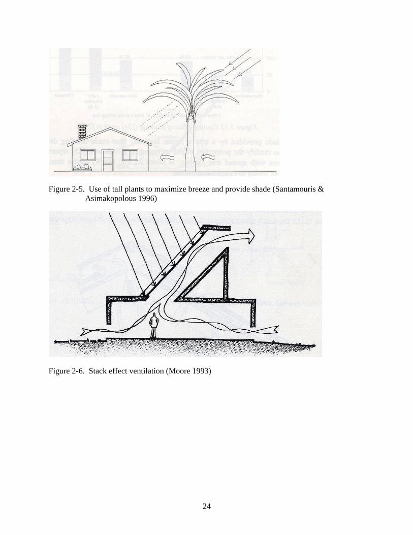
protecting west and east exposures, tall trees will be utilized. Figure 2-5 shows that taller trees
will allow natural breezes to pass, while still shading the house with the higher leaf cover.
18
The design of the interior partitions also plays an important role in maximizing natural
ventilation. If interior partitions are utilized in the home then placing them parallel to the
direction of airflow will have the least effect on airflow (Moore, 1993). With this design criterion
in mind the model home was designed to utilize a more open floor plan. This open floor plan
increases natural ventilation and also natural daylighting (discussed in the natural lighting
section).
Stack effect ventilation is the second natural cooling strategy dealing with ventilation that
can be utilized in a home. The general concept deals with the difference in buoyancies between
warm and cold air. Warm air tends to rise due to its buoyancy and ventilation of this warm air
through upper openings is quite advantageous. With the escape of the warmer air, cooler air is
drawn inside from lower openings, effectively introducing cooler temperatures for interior of the
building. In order to take advantage of the stack effect the model home uses operable clerestory
windows at the highest point in the house. The stack flow of air will be more effective when used
in conjunction with the solar gain in the clerestory due to the elevation of the air temperature
(Awbi 2003). Coupled with the lower window cross ventilation the clerestory windows will use
the stack effect to create livable conditions passively (Figure 2-6).
Daylighting
In the event of a loss of power homes can utilize natural daylighting. The basic idea behind
daylighting for any home is to accept diffuse sunlight from the windows, which will provide
light for the interior of the home. Accepting diffuse and not direct sunlight is an important
concept to reduce unwanted solar heat gains.
In other areas that cannot access the sunlight readily, tube skylights can be installed. Tube
skylights (Figure 2-7) can allow as much as 900 watts of light into a room on a sunny day and as

19
much as 100-500 watts on a cloudy day (Schaeffer & Pratt 1999). These tube skylights do not
allow transmittance of solar radiation, making them more effective in avoiding heat gain.
Natural daylighting is coupled with the clerestory windows already in use with the passive
heating and natural ventilation systems. The major advantage of using clerestory windows is the
fact that they allow light deeper into a space than with windows alone (Crosbie 1998). This is
especially important with an open floor plan house because the clerestory can effectively serve
the large interior portions of the house with natural light.
Avoiding excessive solar exposure during the cooling season directly ties into natural day
lighting and must be addressed to avoid overheating problems. In order to provide effective
thermal protection shading devices should be placed on the exterior of the home (Crosbie 1998).
To overcome an overheating problem during the summer months, when the sun is high in the
sky, overhangs will be installed on the clerestory windows on the south facade. These overhangs
shade the windows during the cooling season when the sun is high in the sky and during the
heating season will allow penetration of direct solar radiation.
Interior shading of the clerestory windows is another aspect of avoiding overheating. Due
to the position of the windows in the home it is necessary to have interior instead of exterior
shading because operation is facilitated with indoor access. For best performance the shading
devices should not only block solar radiation but also provide insulation during the day in the
cooling season and at night in the heating season (Crosbie 1998). Figure 2-8 shows an example
of interior thermal shades that will provide a higher thermal resistance for the clerestory
windows when necessary.
Photovoltaic Power
Providing a secondary form of power is an essential element for passive survivability.
Photovoltaic power generation involves collecting and storing solar energy. Since this energy is

20
free and renewable, photovoltaic power systems are advantageous to passive survivability. These
systems can supply enough power to operate essential appliances during utility service
downtime.
Figure 2-9 shows the basic components and layout of a photovoltaic power system. The
collector located on the roof sends power downstream to the inverter. From the inverter, power
can be supplied to the AC breaker box and battery bank. The battery bank serves as a storage
device for the power. The breaker box controls the circuits, which deliver the photovoltaic
power. Another critical safety component for any photovoltaic power system is the circuit
breaker. This device eliminates the risk of electric shock for anyone servicing the power system.
Rain Water Collection
Present-day houses mainly rely on city water and a loss of water supply to these houses
can cripple their functionality. Within these houses any normal water fixture is rendered useless
unless there is a backup water supply system. To overcome this over reliance on city water one
must look elsewhere for a supply. Located in Florida, one of the wettest states in the country,
rainwater can provide the dependence necessary for passive survivability.
Rainwater collection systems are relatively simple systems and are utilized all over the
world. These systems in general, utilize a number of components (Gould & Petersen 1999):
• A catchment surface where the rainwater runoff is collected • A storage system where the rainwater is stored until required • A delivery system for transporting the water from the catchment to the storage reservoir • An extraction device to take the water from the reservoir
The catchment surface in a residential setting is most often the roof of the house. Utilizing
the roof is advantageous because it does not require any major design criteria to function.
Normally the gutters on a house catch the runoff and direct it to downspouts that discharge to the
21
city storm sewer, but in this case the runoff will be directed to a large cistern. Stored in the
cistern the water will sit until required for use in the home.
This collected rainwater can be used for many purposes. In developing countries some
families are solely dependent on harvested rainwater, but for the purposes in a city, like
Jacksonville, the stored water will be a secondary source of water with the city being the
primary. This secondary water source, during normal operation times, will be mostly used for
gardening and flushing toilets. However during emergency situations this collected water can be
used for survivability purposes ranging from drinking water to clothes washing. Harvesting
rainwater creates the independence a building needs during emergency situations.

22
Figure 2-1. Sun’s path in summer and winter (Naumann, Quivik, Riley, & Sesso 1979)
Figure 2-2. Window overhang blocking sun radiation during summer months (Crosbie 1998)

23
Figure 2-3. Window overhang allowing sun radiation during winter months (Crosbie 1998)
Figure 2-4. Summer/winter tree performance (Santamouris & Asimakopolous 1996)
24
Figure 2-5. Use of tall plants to maximize breeze and provide shade (Santamouris & Asimakopolous 1996)
Figure 2-6. Stack effect ventilation (Moore 1993)

25
Figure 2-7. Tube skylight (Schaeffer & Pratt, 1999)
Figure 2-8. Thermal shade for clerestory windows (Moore 1993)

26
Figure 2-9. Example PV array wiring schematic (freesunpower.com, 2008)
27
CHAPTER 3 RESEARCH METHODOLOGY
Introduction
This thesis is determined to integrate passively survivable techniques into single-family
home construction in Florida. Research started with the creation of a passive survivability
checklist (Appendix A). This checklist served as a guide when consulting libraries for research
materials. Passive design construction texts served as the bulk of information for the thesis.
Using the checklist as a guide and learning from the literature, the various techniques then
needed to be applied to a single-family home in Florida.
Assumptions
Having chosen Jacksonville, Florida, for the location of the model home, assumptions
based on the location were made to justify passive survivability. Choosing an average family size
of 4 people, when the average family size is 3.2 (2006 Census data) was done to add in a factor
of safety for design criteria. The duration for which a family could remain living in the model
home was another critical assumption that was made. A time period of 2 weeks was chosen as
the length of time a family could survive. Choosing this time period was based on a 2006
hurricane workshop after the Katrina and Rita hurricanes. The time period of two weeks was the
average utility downtime for category 3 storms. Although this paper is not exclusively about
passively surviving hurricane damage, this type of weather damage has the highest probability of
affecting local utilities thereby justifying setting the length of survivability at 2 weeks.
Creating a Model
With a 2-week survivability duration, the design stages of the model home included
sketching a model home. The main purpose of developing the model was to showcases the
home’s various passive survivability techniques. Google Sketch-Up was used to design a basic

28
model home for single-family construction in Florida. Screen shots of the model home are
referenced as figures in the results section. The models interrelated strategies can serve as a
design strategy for designers and builders interested incorporating passive survivability into
building design.

29
CHAPTER 4 RESULTS
Heating and Cooling
Applying the concepts covered in the literature review the model home employs passive
solar heating and cooling strategies. For the model home, located in Florida, the southern face of
the house will receive the most sunlight per day and windows placed here will prove the most
efficient for solar radiation uses.
The model home (Figure 4-1) is orientated with the main facades of the house facing to the
south and north. East and west exposures are minimized because controlling solar radiation
becomes too difficult. Passively heating the home will be accomplished using solar radiation.
The transmittance of solar radiation into the home will be allowed due to the low elevation of the
sun in respect to the windows (Figure 4-2). During the winter months the deciduous trees will
loose their leaves, allowing the sun’s solar radiation to pass through into the home to be stored in
the floors and walls. This stored heat can then be slowly released to the ambient indoor air during
winter.
During the summer the opposite passive solar design approach is employed. In this case
heat gain prevention is the goal and this is accomplished by limiting the amount of solar
radiation allowed into the home. With the sun’s elevation angle much higher, roof overhangs
(Figure 4-2) will block solar radiation transmittance to the windows. Figure 4-2 also shows that
due to the sun’s low elevation angle during the time period of October 1st to May 1st, solar
radiation is allowed into the home. The deciduous trees, now covered with leaves, will provide
added protection to the low southern facing windows. Thermal shades (Figure 2-8) will be
provided for all glazed surfaces of the home. Operation of these shades will limit the heat gains
in the model home, avoiding overheating problems during the summer.

30
Natural Ventilation
Natural ventilation combined with passive cooling will provide a more habitable
environment for the model home. It is important to remember that this design strategy of
combining natural ventilation with passive cooling will be used in emergency situations and will
extend the thermal comfort zone for the habitable indoor space. Having stated this, natural
ventilation of the model home will be carried out by applying lessons learned from cross
ventilation and stack effect ventilation.
Figure 4-3 shows the layout of the model home with a very large central area. This area
was designed to create an open layout for the most often occupied rooms of the house. The other
rooms of the house are located on the east and west sides of the home to eliminate the direct
solar gain into the main living area. The garage, bedrooms, bath, and utility room could occupy
either side of the home but have been located in this layout to reduce heat gain into the home.
This open floor plan benefits cross ventilation because there are no walls impeding the natural
crosswinds. Operable windows, on the north and south side, with equal opening size will serve as
the inlet and outlet for the cross draft.
The rooms on the east and west end of the home will also utilize natural ventilation in the
case of the active cooling system failure. Double hung windows are placed in these rooms so
one-sided ventilation could be possible. These double hung windows, with their lower and upper
openings, will effectively allow warm air to rise out of the room while drawing in cooler air from
the lower opening.
The stack effect was applied to the model home by designing operable clerestory windows
at the top of the home. These openings, due to their high position in the home, will vent warm air
to the outdoors while allowing cooler outside air in from the lower window openings. Stack

31
effect combined with cross ventilation will remove unwanted heat from the model home along
with creating ventilation that will cool the occupants.
Landscaping for the model home not only blocks solar radiation but will also aid in
ventilation. The south elevation utilizes low vegetation around the window openings (Figure 4-
4). This vegetation creates a cooler microclimate, which will provide cooler air for ventilation.
The deciduous trees are also located to funnel air currents into the home. The east and west side
landscaping plan can be seen in Figure 4-5. These two sides of the home utilize taller trees,
which provide shade while also providing an unobstructed path for ventilation.
Daylighting
In the event of a power loss the model home’s natural daylighting will provide sufficient
light indoors. The clerestory windows allow deep penetration of light into the large open area of
the home. The color white was chosen for the home’s various materials finishes. Two prime
examples of the white finish are the roof and interior walls, which are utilized to reflect light into
the living space. Glazed surfaces on the north end of the home accept reflected light, aiding in
the natural daylighting strategy.
While the model home utilizes landscaping to shade windows from direct solar radiation
this rejection of usable light is made up for with the acceptance of light from the clerestory
overhead. In addition to the sunlight allowed through the clerestory and exterior windows the
model home will also utilize tube skylights. These will be installed on the exterior rooms located
on the east and west side of the home, which include the bedrooms, garage, utility room, and
bathroom. These special skylights provide overhead sunlight through a mirror finished aluminum
pipe through the roof of the house. These tubes skylights (Figure 2-7) are simple roof penetrating
units that allow natural light into the model home without allowing solar radiation. These tube

32
skylights will be installed in the rooms that do not have access to the overhead light provided by
the clerestory windows.
Photovoltaic Solar Power Generation
In the event of a power loss, daylighting design strategies work well in conjunction with
the sun, but during the nighttime hours, lighting is required not to mention the fact that power is
needed to run essential appliances. The model home will utilize a small photovoltaic array to
supply enough power for small task lighting and essential appliances.
The array will be located on the south roof of the model home. The array panels will be
built into the roof, meaning they will take the place of the roofing material, creating a smooth
flush roof surface (Figure 4-6). The reason for this is to protect the array from wind damage. A
smooth roof surface will not create any uplift potential for the panels as compared to panels tilted
and mounted above the roof surface. Designing the roof pitch to match the latitude of 30 degrees
for Jacksonville will produce the highest energy efficiency for the PV array.
The PV array for the model home will be a grid-connected system. This means that the
power supplied from the array during normal operations (grid power available) will be fed back
into the city power grid. The home will have an inverter, which will convert the DC power into
AC power, and the utility company will install a separate PV power meter. This additional meter
runs backwards, so in essence the homeowner is billed for the power differential usage between
the PV generated and the power usage of the home.
During emergency situations, when the city power grid is down the model home’s PV
system will provide power for the home. The PV system running independently of the city power
will be limited in its power supply. The model home has been designed to utilize only chosen
appliances in this instance. This emergency circuit, fitted with a breaker, can be switched on
when city power fails. The breaker serves as a safety device in the event of service work. The
33
home’s emergency circuit has batteries downstream which are charged and ready to supply
power during the nighttime. The appliances selected were based on what could not be provided
passively from the houses various other passive technologies. Small lighting fixtures throughout
the home will be provided power for nighttime use due to the absence of daylighting at later
hours of the day. A small refrigerator can also be connected to the emergency circuit so essential
food can be kept cool. Another appliance that was taken into account for the emergency circuit is
the power needed to charge a cell phone or laptop computer, in the event of an emergency when
communication technology is essential.
Sizing the system included the use of the system sizing estimate program obtained from
freesunpower.com. The software calculated the amount of 80-100 Watt panels and battery
storage size based on the following inputs:
• 1 4-5 cubic foot fridge operating with below normal usage • 200 watts of lighting operating for 3 hours a day • 1 Laptop computer operating for 2 hours a day
The outputs of the software can be seen in Figure 4-7. As shown, three 80-100 watt PV
panels are required with seven 12-volt batteries operating at 105 amp hours. The wiring
schematic as seen in Figure 2-9 is an example of how the PV array would be wired for the model
home. Although the AC generator is not included in the model’s home backup power, this figure
displays a basic wiring schematic for the model home. The AC (alternating current) out breaker
box as seen in the schematic will control the various emergency circuits throughout the house,
and will be located in the utility room. These circuits will each have small emergency lighting
fixtures that can be switched on and off via the individual breaker. Included in the emergency
circuit breaker panel will be a circuit for an outlet run in the utility room, which will service the
small fridge as well as a laptop or cellular phone.
34
Water
The model home utilizes collected rainwater as a secondary source of water for the house.
Located in Florida, one of the wettest states in the country, rainwater is abundant during most
times of the year. Utilizing this rainwater allows the model home to be more independent from
the local utilities. In the event of a loss of city water the occupants of the home can rely on their
secondary water source, the harvested rainwater.
The catchment system for the model home is the roof. The roof is sloped to the south and
north sides of the model home which will direct runoff into the delivery system or gutters. The
gutters are sloped towards the west end of the house. This slope will allow for the water to be fed
into the reservoir by means of gravity. The gutters will also provide a primary point of cleansing
for the water. Utilizing a self cleaning component on the downspout of the gutters (Figure 4-8)
debris washed into the gutters will be separated and kept out of the storage device. The storage
system for the model home consists of a large underground cistern made of cement. This is
where the rainwater is stored until required by the fixtures. The event of overflow may seem
unlikely but must be addressed nonetheless. The tank will be fitted with an overflow device that
allows excess water to be diverted into a drip line in the garden of the home.
Sizing the cistern depends on multiple factors and for the model home located in
Jacksonville, these factors need to be taken into consideration. The tank will need a capacity of
around 2,000 gallons based on the calculations given from the Harvested Rainwater Guidelines
on the Green builder website. The average size family in Jacksonville, according to the U.S.
census bureau is was 3.20 in 2006 so to be safe in designing the cistern size 4 people are
assumed. Using 40 gallons per person per day is a generous amount according to the rainwater
harvesting guidelines. Using the survivability duration of 14 days from the methodology section,

35
the tank is sized by multiplying the 4 people, 40-gallon/ person per day, and the 14-day duration
together to conclude that a 2,200-gallon cistern is required.
This cistern water will be extracted by means of an electric pump during normal periods
when the house is using grid energy. The extraction line will be fitted with a floating suction line
(Figure 4-9), which will extract water from the upper storage capacity of the cistern, which is
seen as the cleanest water in storage. In the event of a power loss the extraction method for the
rainwater is a simple hand pump.
The extracted water from the cistern will be taken to a smaller holding tank in the upper
loft area of the mechanical room (Figure 4-10) where it will be stored. This smaller holding tank,
due to its elevation in the house, will use gravity as a means for delivering the rainwater to the
fixtures, thereby becoming independent of city water pressure. Two float switches, one in the
cistern and one in the upper holding tank, will activate the electric pump which moves water
from the cistern to the holding tank. The electric pump will be shut off when either the upper
holding tank is full or the cistern is empty. The latter event, however unlikely, will be minimized
with a make-up inlet of city water in the rare case that the cistern is dry. This city makeup water
will be controlled by another float switch located in the underground cistern.
The design of the model home has a hybrid water deployment system. Collected rainwater
will be used mainly for flushing of toilets and outside watering. Another tap for harvested
rainwater is located in the utility room at the slop sink. In the case of a loss of city water this tap
can service the slop sink for clothes washing and other essential needs. Operation of the hand
pump in the utility room will fill the upper holding tank and then the toilet, slop sink, and
exterior hose bib remain operable due to gravity delivery.

36
The issue of wastewater systems backing up or failing is another concern that the model
home design has taken into account. In the instance of waste water systems failure all operation
of city connected water fixtures should be ceased. The slop sink in the utility room will now
serve as the home’s central water fixture (solid waste disposal is covered in the following
section). This drainage system for the slop sink is separate from all other fixtures in the house.
The drainage system consists of a rock and sand bed in the yard. This system is very permeable
and able to handle large amounts of wastewater. As the water runs through the layers of the
drainage bed it is also cleansed before returning to the water table below. Since the system is
located underground, access hatches must be installed to service the filter and perform other
repairs. This separate drainage system gives the model home independence when wastewater
service disruption occurs.
Surviving in the Model Home
There are many issues involved with surviving in the model home that cannot be addressed
by specific design techniques. This section’s aim is to cover these various aspects of survival.
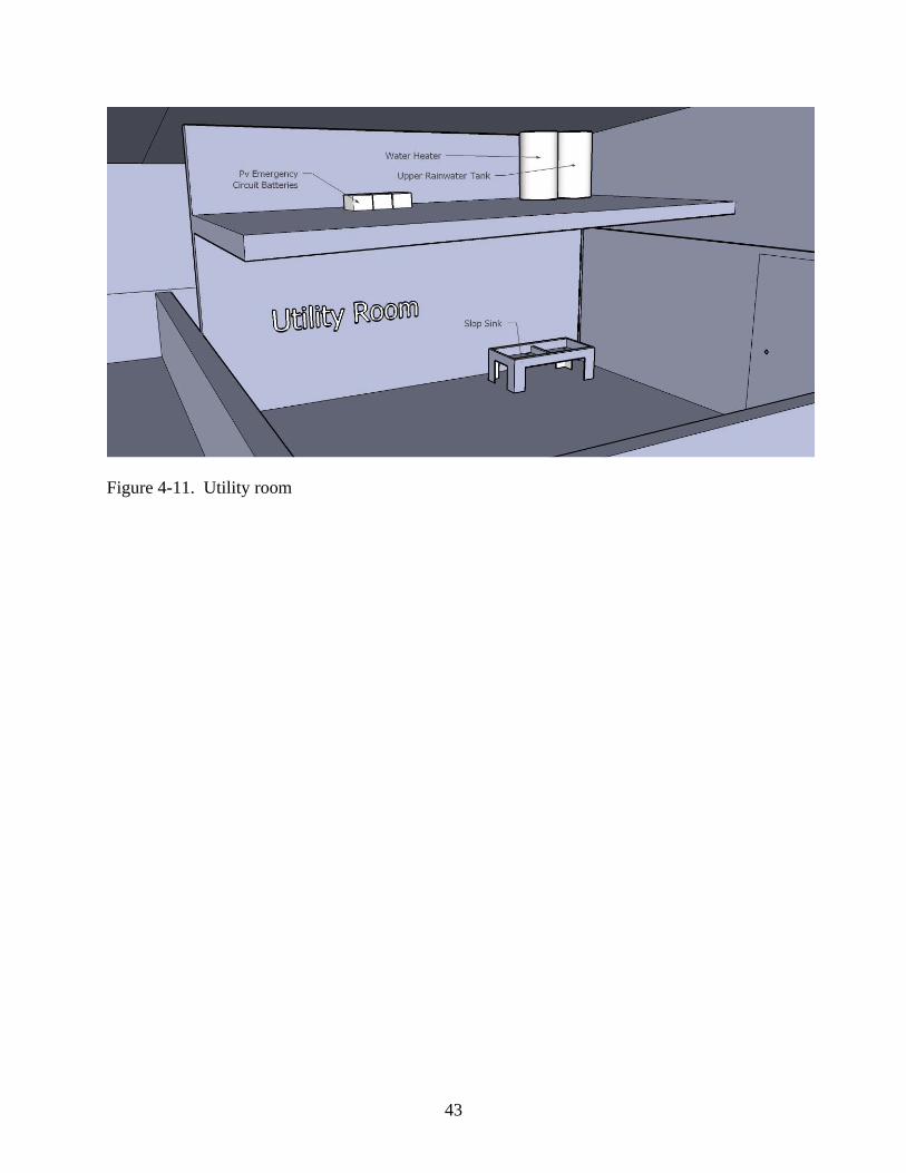
The utility room (Figure 4-11) at the east end of the house can serve a wide variety of purposes
for the model home. Due to the design of the ceiling height, space was limited to store certain
mechanical equipment, so the loft was added to the utility room to house the upper rainwater
harvesting tank, hot water heater, and the components for the PV system.
Another design strategy for this room was to place it in the interior of the home so that the
only openings to the outside would be a solid storm door. This room can be utilized as a shelter
during storms because there is no danger of flying debris breaking through windows. With such
solid construction this serves as the house’s main food storage area. Keeping a stocked inventory
of dried and canned food will provide sustenance during emergency situations. With the
harvested rainwater tank conveniently located above drinking water can be provided by means of
37
gravity through an outlet. This outlet will have the capability to be fitted with a water filter,
which can be changed when necessary.
Cooking in the event that gas utilities fail will be accomplished with the use of propane.
Twenty-pound backup tanks with a portable stovetop will provide cooking needs for the family.
Cooking scraps and waste that are organic can be decomposed in a composting pile in the yard in
the case that waste disposal is unavailable. Composting solid waste is another issue that the
model home must employ in the case that city sewer lines fail. A composting toilet is a relatively
low priced option that can operate without water and wastewater utilities. A self-containing
model can sit dormant until needed and the non-electric model installation only requires a small
vent to the roof.
As mentioned previously in the Water section, the slop sink in the utility room will
service many needs of the occupants in the case of utility failures. The rainwater tap becomes the
access point for water related activities. Due to it’s gravity fed capability and separate waste
water system, this sink can operate completely independently of any city utilities. The various
systems and elements that are operated from this room include rainwater access and emergency
PV circuit control, as well as serving as a place of shelter and food storage. The utility room
itself becomes the central hub of activity during an emergency situation.

38
Figure 4-1. Orientation of model home
Figure 4-2. Sun elevation for May 1st & October 1st

39
Figure 4-3. Layout of model home
Figure 4-4. South elevation landscaping plan

40
Figure 4-5. West elevation landscaping plan
Figure 4-6. In-roof installation of PV array (Deutsche Gesellschaft fu ̈r Sonnenenergie, 2005)

41
Figure 4-7. Output data for PV system (freesunpower.com 2008)
Figure 4-8. Self-cleaning gutter component (Gould 1999)

42
Figure 4-9. Floating extraction filter (Gould 1999)
Figure 4-10. Riser diagram of rainwater delivery system
43
Figure 4-11. Utility room
44
CHAPTER 5 CONCLUSION
The model home effectively utilizes passive heating, cooling, lighting, and water saving
technologies. These technologies coupled together have the primary benefit of allowing the
occupants to survive in the model home during non-utility service time. Justification is best
accomplished by looking at the secondary benefits of designing a passively survivable house.
These benefits, which are secondary to creation of a non-utility dependant house, deal with
environmental and cost savings concerns.
Many of the technologies applied to the model home, in nature, are green technologies.
Natural ventilation and daylighting, along with passive heating and cooling, substantially reduce
the amount of energy the model home needs to operate. This allows for a lower size of heating
and cooling equipment that will be installed on the house. The duration of operation time for this
equipment will also be significantly reduced due to the design strategies that prevent large indoor
thermal swings. During daylight hours, the model home will not require much, if any, power to
light the interior of the home. The effective use of daylighting keeps lighting power demand low,
again reducing the amount of power required from the grid.
The rainwater harvesting system will effectively reduce the amount of water demand for
the home. With water crises emerging throughout the country, the rise of water prices is
inevitable, so any step towards reducing the amount of water consumed by the household is
advantageous to not only the environment but also in keeping operating costs low. According to
the harvesting rain water table in the harvesting rainwater guidelines, the model home’s 2500sf
roof in Jacksonville, which receives on average 52 inches of rainfall per year, will have access to
over 73 thousand gallons of water annually. With that astounding amount of water it is no
wonder why Florida is the wettest state in the nation. The question arises as to why more houses

45
do not employ rainwater harvesting, when such a valuable resource can be collected with
minimal effort.
The combination of the various passively survivable technologies led to the creation of a
residential model. The ability to provide critical life support functions during times of utility
downtime has been effectively designed and applied to the model home. In the event of an
emergency, the loss of any number or combination of utilities has been accounted for when
designing the various systems.
The passive heating and cooling strategies that were designed for the model home allow it
to provide the thermal conditions necessary to survive indoors, while being completely
dependent from local utilities. In the event of a loss of power to the home, daylighting provides
sufficient light indoors, while the small PV array provides necessary backup power for essential
appliances. Loss of city water, while not a very common occurrence, it is a possibility in the
future especially with the recent occurrence of water crises throughout the nation. The rainwater
harvesting system is designed as a hybrid water distribution system, which can effectively
operate during times of no water utility service, as well as reduce the amount of water consumed
by the household.
With the creation of this passively survivable residential model the foundation for new
building design criteria has been laid. In the future, designers and builders can look upon this
thesis as a stepping-stone to researching and developing new technologies and applications that
could extend to various climates as well as building types.
Recommendations for future research would be an investigation into other various green
technologies that improve the passive survivability of single-family homes. Testing the various
46
design elements and determining their efficiencies is the next step in developing passive
survivability into our built environment.
Recommendations for designers and builders would be to adapt passive survivability into
larger residential and commercial buildings. Integrating the idea of passive survivability into
building codes will provide safer and more habitable shelters during post disaster times.

47
APPENDIX PASSIVE SURVIVABILITY CHEKLIST
• Passive Heating o Glazing orientation/sizing depending on latitude o Mass storage devices depending on building materials
• Passive Cooling o Overhang design depending on latitude o Night cooling depending on climate region
• Natural Ventilation o Stack effect depending on design of home o Cross ventilation depending on size/layout of home
• Daylighting o Glazing depending on design of home
(i.e. Clerestory window, tube skylights) • Rainwater Harvesting
o Cistern capacity depending on number of occupants • Photovoltaic Power
o Array size depending on amount of power required o Array mounting angle depending on latitude

48
LIST OF REFERENCES
All-Industry Research Advisory Council. (1989). Surviving the storm: building codes, compliance and the mitigation of hurricane damage. Oak Brook, Ill: All-Industry Research Advisory Council.
Awbi, H. B. (1991). Ventilation of buildings. London: E & FN Spon.
Awbi, H. B. (2003). Ventilation of buildings. London: Taylor & Francis.
Black, R. J. (1993). Florida climate data. [Gainesville, Fla.]: University of Florida Cooperative Extension Service, Institute of Food and Agriculture Sciences, EDIS. http://purl.fcla.edu/UF/lib/EH105.
Crosbie, M. J., (Ed.) (1998). The Passive Solar Design and Construction Handbook. New York: John Wiley & Sons, Inc.
Crowley, J. S., & Zimmerman, L. Z. (1984). Practical passive solar design: a guide to homebuilding and land development. An Energy learning systems book. New York: McGraw-Hill.
Deutsche Gesellschaft fu ̈r Sonnenenergie. (2005). Planning and installing solar thermal systems: a guide for installers, architects, and engineers. London: James & James/Earthscan.
Energy Efficiency and Renewable Energy Clearinghouse (U.S.). (1994). Solar heating and you. Washington, D.C.?: Energy Efficiency and Renewable Energy Clearinghouse.
Energy Efficiency and Renewable Energy Clearinghouse (U.S.). (1996). Solar water heating. [Washington, D.C.?]: Energy Efficiency and Renewable Energy Clearinghouse.
Galloway, T. R. (2004). Solar house: a guide for the solar designer. Oxford: Architectural Press.
Gould, J., & Nissen-Petersen, E. (1999). Rainwater catchment systems for domestic supply: design, construction and implementation. London: Intermediate Technology Publications.
Hestnes, A. G., Hastings, R., & Saxhof, B. (1997). Solar energy houses: strategies, technologies, examples. London: James & James.
Kibert, C. J. (2008). Sustainable construction: green building design and delivery. Wiley book on sustainable design. Hoboken, N.J.: John Wiley & Sons.
Littlefair, P. J. (2000). Environmental site layout planning: solar access, microclimate and passive cooling in urban areas. London: BRE Publications.
Moore, F. (1993). Environmental control systems: heating, cooling, lighting. New York: McGraw-Hill.

49
Naumann, H., Quivik, F., Riley, T., & Sesso, J. (1979). Natural cooling for homes: low-energy concepts. Butte, Mont: National Center for Appropriate Technology.
Santamouris, M., & Asimakopoulos, D. (1996). Passive cooling of buildings. London: James & James.
Schaeffer, J., & Pratt, D. (1999). The Real Goods solar living sourcebook: the complete guide to renewable energy technologies and sustainable living. Ukiah, Calif: Real Goods Trading Corp.
Skistad, Håkon. Displacement Ventilation. New York: John Wiley & Sons, 1994.
United Nations Centre for Human Settlements. (1990). National design handbook prototype on passive solar heating and natural cooling of buildings. Nairobi: United Nations Centre for Human Settlements (Habitat).
United Nations Environment Programme. (1983). Rain and stormwater harvesting in rural areas: a report. Dublin: Published for the United Nations Environment Programme by Tycooly International Pub.
Van Dresser, P. (1995). Passive solar house basics. Santa Fe, N.M.: Ancient City Press.
Williams, J. M., Duedall, I. W., & Doehring, F. (1997). Florida hurricanes and tropical storms. Gainesville: University Press of Florida.
Wilson, Alex. Passive Survivability: A New Design Criterion for Buildings. Environmental Building News. 2006. Accessed on January 21, 2008 from http://www.buildinggreen.com/auth/article.cfm?fileName=150501a.xml

BIOGRAPHICAL SKETCH
Andrew Joseph Mejia was born in 1985 to become the 5th member of the Mejia family. His
hometown of Oak Park, Illinois is where he attended Fenwick High School. Purdue University in
West Lafayette, Indiana is where Andrew received his Bachelors degree in Building
Construction Management in the spring of 2007. Fall of 2007 he started graduate school at The
University of Florida. Andrew received his Masters of Science in Construction Management
from the M.E. Rinker, Sr. School of Building Construction in the summer of 2008. He has
moved back to Chicago to begin work in the construction industry.