parts & service manual for monroe pin hitches · parts & service manual for monroe pin...
TRANSCRIPT
Monroe Snow & Ice Control1051 W. 7th Street • Monroe, WI 53566USA: 877-834-9049 • Fax: 608-329-8488www.monroetruck.com
05090293-412/2/2013
Parts & Service Manualfor
MONROE PIN HITCHES

2
33
Table of Contents
General Information 4
How to Order Parts 4
Return Policy 4
Safety Instructions 5
Maintenance Instructions 6
Hydraulic Schematics 7
Installation Instructions ???
Replacement Parts 15
Warranty 45
4
General Information
• Use only Monroe Truck Equipment O.E.M. replacement parts. Failure to do so will void the warranty.
• Location descriptions are noted in direction of travel (i.e. front, rear, left and right).
• Delivery of replacement parts is subject to our sales delivery terms.
• Replacement parts listed in this manual reflect the most common items for thisproduct. If you do not find the part you require, please call your distributor.
• Monroe Truck Equipment reserves the right to make revisions or alterations to the parts manual at any time.
How to Order Parts
To order or inquire about replacement parts, please contact the distributor or store thatthe product was purchased through. To speed the information flow, please have thefollowing information available:
• Model Number• Serial Number• Part Number and/or Description of the Part• Quantity Needed
For further information about Monroe Truck Equipment replacement parts, please call877-834-9049.
Return Policy
Merchandise returned to Monroe Truck Equipment must have a Warranty Service Re-quest (WSR) form filled out completely and signed by authorized personnel.
To get your WSR form for whole goods, call Snow & Ice Sales at 800-880-0109.
To get your WSR form for replacement parts, call Warranty at 877-834-9049..
All returned items are subject to a 15% restocking fee and must be sent freightpre-paid.
5
Safety Instructions
Before working under the vehicle or around the spreader, shut off the truck engine and remove the key from the ignition. Prevent accidental startup and operation to avoid personal injury!
• Read all installation, safety and maintenance instructions completely before operating this equipment
• Keep all personnel clear of moving parts while equipment is being operated.
• Do not operate equipment in need of maintenance! Repair immediately!
• While operating this equipment, use common sense, use caution, be alert and be safety-conscious.
NOTE: Before installation of any hitch, or maintenance to hitch or truck, be sure toapply parking brake, chock the rear wheels and remove the key from the ignitionswitch.
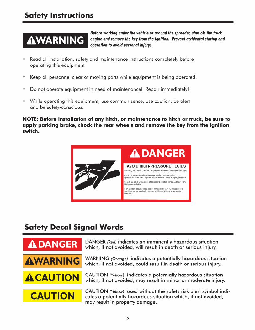
AVOID HIGH-PRESSURE FLUIDSEscaping fluid under pressure can penetrate the skin causing serious injury.
Avoid the hazard by relieving pressure before disconnecting hydraulic or other lines. Tighten all connections before applying pressure.
Search for leaks with a piece of cardboard. Protect hands and body from high pressure fluids.
If an accident occurs, see a doctor immediately. Any fluid injected into the skin must be surgically removed within a few hours or gangrene may result.
DANGER (Red) indicates an imminently hazardous situationwhich, if not avoided, will result in death or serious injury.
WARNING (Orange) indicates a potentially hazardous situationwhich, if not avoided, could result in death or serious injury.
CAUTION (Yellow) indicates a potentially hazardous situationwhich, if not avoided, may result in minor or moderate injury.
CAUTION (Yellow) used without the safety risk alert symbol indi-cates a potentially hazardous situation which, if not avoided,may result in property damage.
Safety Decal Signal Words
6
Maintenance Instructions
Before working under the vehicle or around the spreader, shut off the truck engine and remove the key from the ignition. Prevent accidental startup and operation to avoid personal injury!
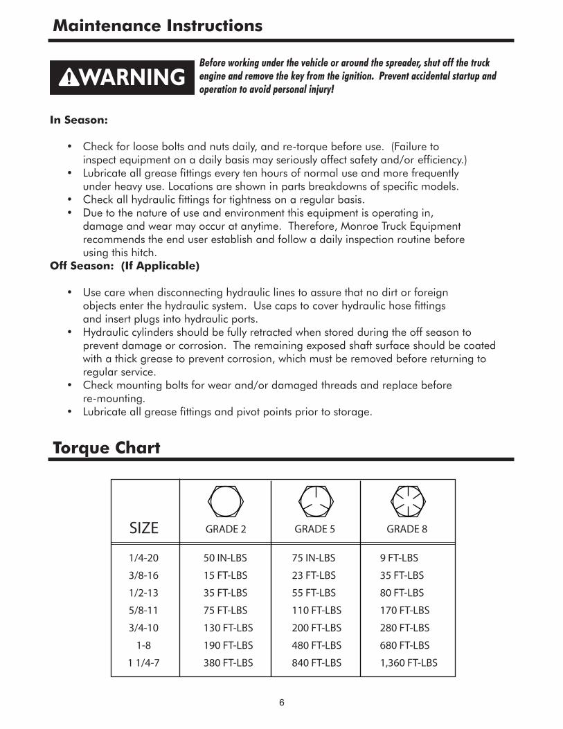
Torque Chart
In Season:
• Check for loose bolts and nuts daily, and re-torque before use. (Failure to inspect equipment on a daily basis may seriously affect safety and/or efficiency.) • Lubricate all grease fittings every ten hours of normal use and more frequently under heavy use. Locations are shown in parts breakdowns of specific models. • Check all hydraulic fittings for tightness on a regular basis. • Due to the nature of use and environment this equipment is operating in, damage and wear may occur at anytime. Therefore, Monroe Truck Equipment recommends the end user establish and follow a daily inspection routine before using this hitch.Off Season: (If Applicable) • Use care when disconnecting hydraulic lines to assure that no dirt or foreign objects enter the hydraulic system. Use caps to cover hydraulic hose fittings and insert plugs into hydraulic ports. • Hydraulic cylinders should be fully retracted when stored during the off season to prevent damage or corrosion. The remaining exposed shaft surface should be coated with a thick grease to prevent corrosion, which must be removed before returning to regular service. • Check mounting bolts for wear and/or damaged threads and replace before re-mounting. • Lubricate all grease fittings and pivot points prior to storage.
1/4-20
3/8-16
1/2-13
5/8-11
3/4-10
1-8
1 1/4-7
50 IN-LBS
15 FT-LBS
35 FT-LBS
75 FT-LBS
130 FT-LBS
190 FT-LBS
380 FT-LBS
75 IN-LBS
23 FT-LBS
55 FT-LBS
110 FT-LBS
200 FT-LBS
480 FT-LBS
840 FT-LBS
9 FT-LBS
35 FT-LBS
80 FT-LBS
170 FT-LBS
280 FT-LBS
680 FT-LBS
1,360 FT-LBS
SIZE GRADE 2 GRADE 5 GRADE 8
7
Hydraulic Schematic
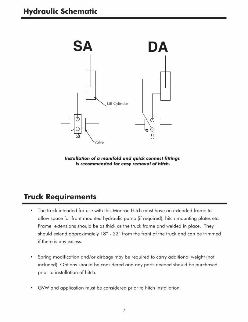
Valve
Lift Cylinder
Installation of a manifold and quick connect fittingsis recommended for easy removal of hitch.
Truck Requirements
• The truck intended for use with this Monroe Hitch must have an extended frame to
allow space for front mounted hydraulic pump (if required), hitch mounting plates etc.
Frame extensions should be as thick as the truck frame and welded in place. They
should extend approximately 18” - 22” from the front of the truck and can be trimmed
if there is any excess.
• Spring modification and/or airbags may be required to carry additional weight (not
included). Options should be considered and any parts needed should be purchased
prior to installation of hitch.
• GVW and application must be considered prior to hitch installation.
8
These mounting instructions are intended as a guide to aid you in the installation of your Monroe Hitch.All dimensions noted in the instructions are approximate and may vary due to: make and model of chassis,tire size, type of suspension, customer preference, and interference caused by immovable attachments.
Monroe Truck Equipment assumes no responsibility for improper installation, unless installed at a Mon-roe Truck Equipment location. Mounting location should be discussed by the end-user and the installer
prior to installation in order to achieve the best possible installation.
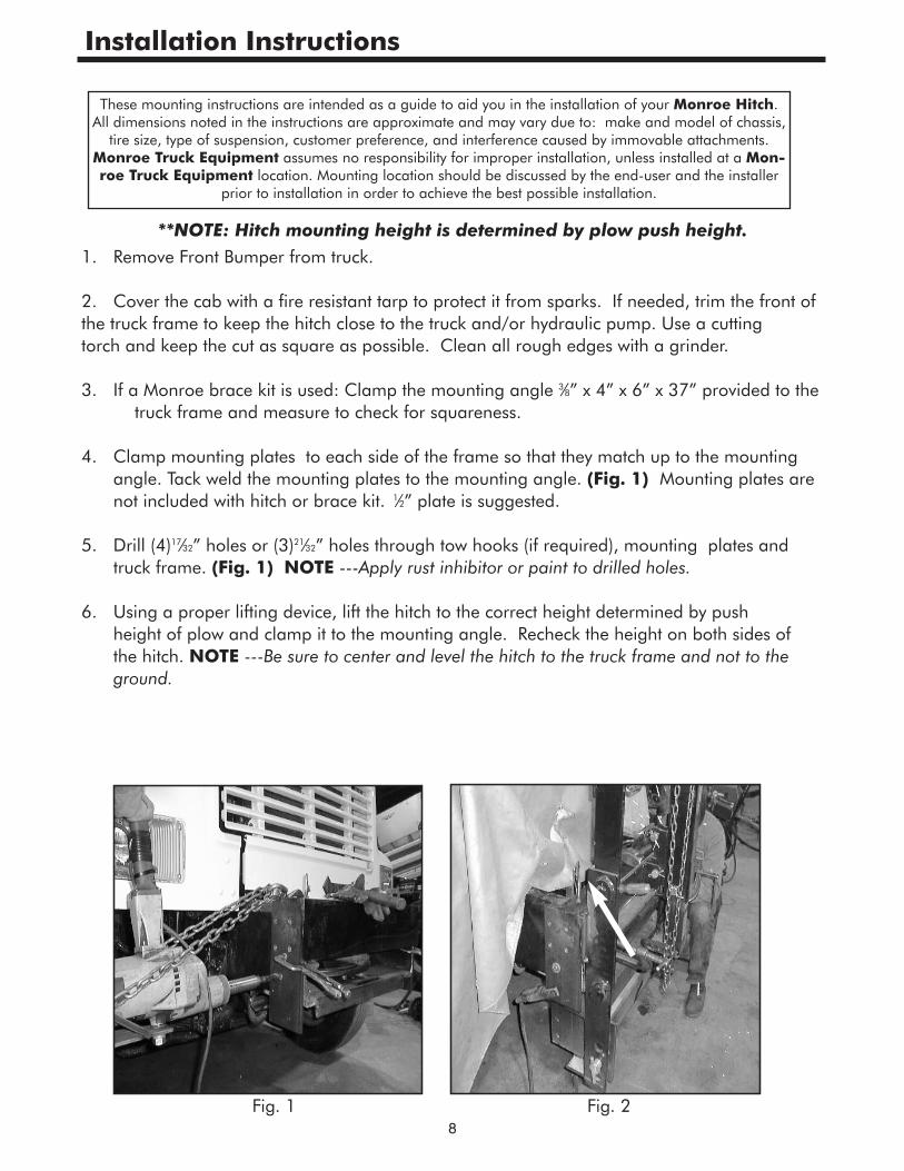
**NOTE: Hitch mounting height is determined by plow push height.1. Remove Front Bumper from truck. 2. Cover the cab with a fire resistant tarp to protect it from sparks. If needed, trim the front of the truck frame to keep the hitch close to the truck and/or hydraulic pump. Use a cutting torch and keep the cut as square as possible. Clean all rough edges with a grinder. 3. If a Monroe brace kit is used: Clamp the mounting angle 3⁄8” x 4” x 6” x 37” provided to the truck frame and measure to check for squareness. 4. Clamp mounting plates to each side of the frame so that they match up to the mounting angle. Tack weld the mounting plates to the mounting angle. (Fig. 1) Mounting plates are not included with hitch or brace kit. 1⁄2” plate is suggested. 5. Drill (4)17⁄32” holes or (3)21⁄32” holes through tow hooks (if required), mounting plates and truck frame. (Fig. 1) NOTE ---Apply rust inhibitor or paint to drilled holes. 6. Using a proper lifting device, lift the hitch to the correct height determined by push height of plow and clamp it to the mounting angle. Recheck the height on both sides of the hitch. NOTE ---Be sure to center and level the hitch to the truck frame and not to the ground.
Fig. 1 Fig. 2
Installation Instructions
9
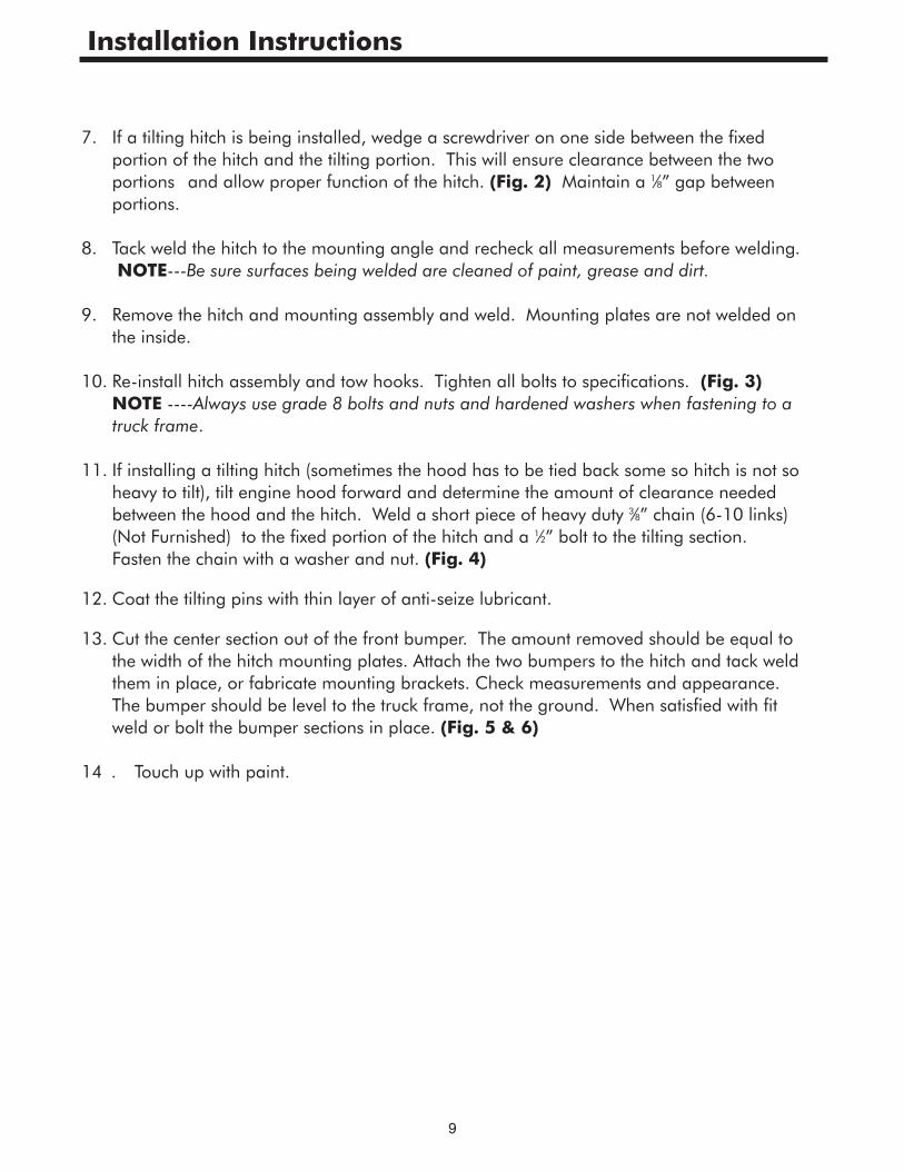
7. If a tilting hitch is being installed, wedge a screwdriver on one side between the fixed portion of the hitch and the tilting portion. This will ensure clearance between the two portions and allow proper function of the hitch. (Fig. 2) Maintain a 1⁄8” gap between portions.
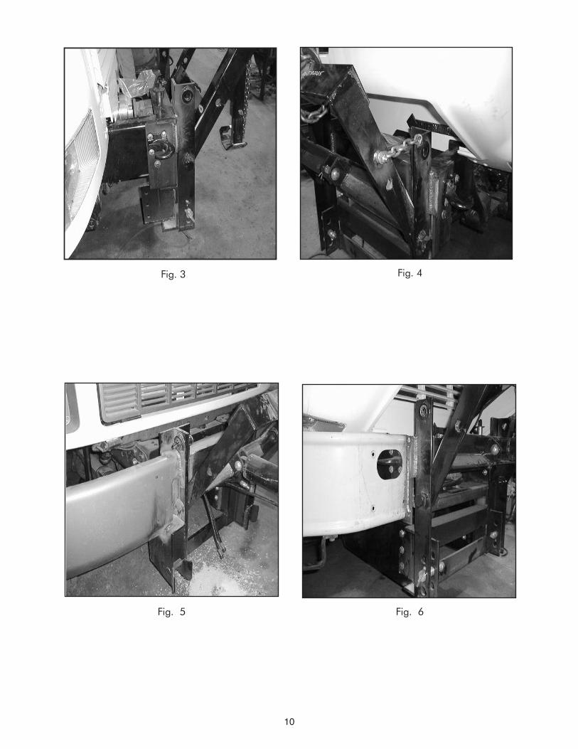
8. Tack weld the hitch to the mounting angle and recheck all measurements before welding. NOTE---Be sure surfaces being welded are cleaned of paint, grease and dirt. 9. Remove the hitch and mounting assembly and weld. Mounting plates are not welded on the inside. 10. Re-install hitch assembly and tow hooks. Tighten all bolts to specifications. (Fig. 3) NOTE ----Always use grade 8 bolts and nuts and hardened washers when fastening to a truck frame. 11. If installing a tilting hitch (sometimes the hood has to be tied back some so hitch is not so heavy to tilt), tilt engine hood forward and determine the amount of clearance needed between the hood and the hitch. Weld a short piece of heavy duty 3⁄8” chain (6-10 links) (Not Furnished) to the fixed portion of the hitch and a 1⁄2” bolt to the tilting section. Fasten the chain with a washer and nut. (Fig. 4) 12. Coat the tilting pins with thin layer of anti-seize lubricant. 13. Cut the center section out of the front bumper. The amount removed should be equal to the width of the hitch mounting plates. Attach the two bumpers to the hitch and tack weld them in place, or fabricate mounting brackets. Check measurements and appearance. The bumper should be level to the truck frame, not the ground. When satisfied with fit weld or bolt the bumper sections in place. (Fig. 5 & 6)
14 . Touch up with paint.
Installation Instructions
10
Fig. 4Fig. 3
Fig. 5 Fig. 6
11
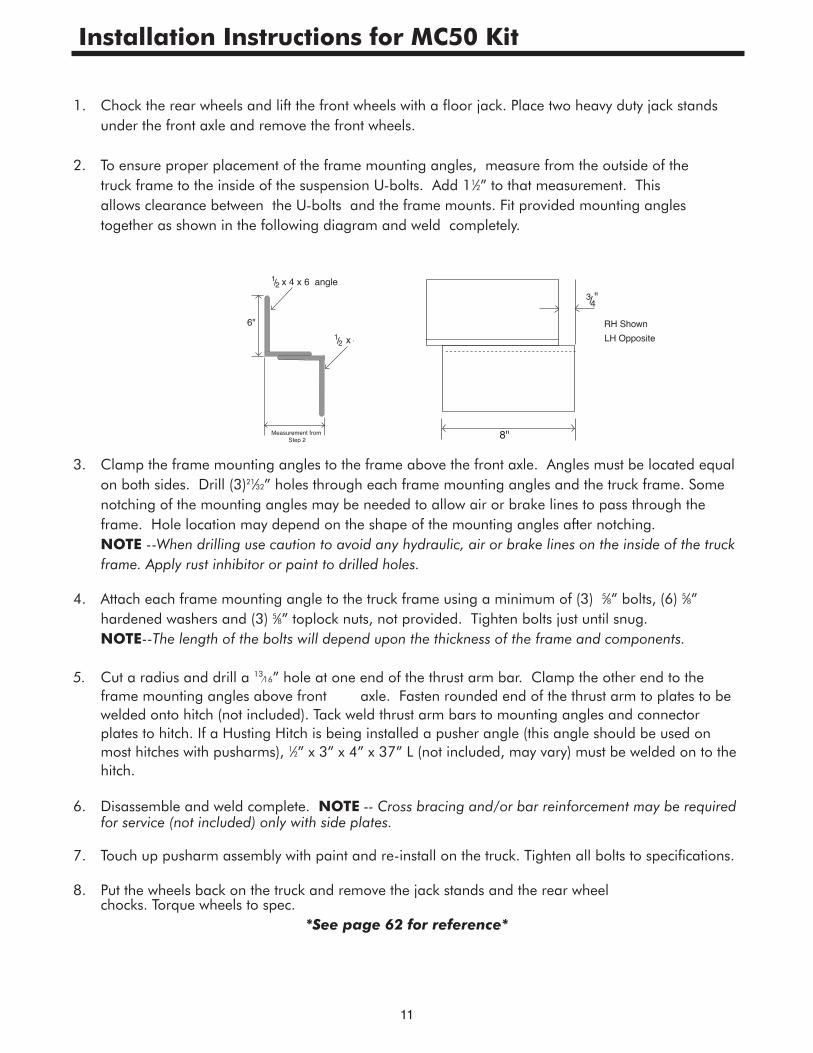
1. Chock the rear wheels and lift the front wheels with a floor jack. Place two heavy duty jack stands under the front axle and remove the front wheels.
2. To ensure proper placement of the frame mounting angles, measure from the outside of the truck frame to the inside of the suspension U-bolts. Add 11⁄2” to that measurement. This allows clearance between the U-bolts and the frame mounts. Fit provided mounting angles together as shown in the following diagram and weld completely.
3. Clamp the frame mounting angles to the frame above the front axle. Angles must be located equal on both sides. Drill (3)21⁄32” holes through each frame mounting angles and the truck frame. Some notching of the mounting angles may be needed to allow air or brake lines to pass through the frame. Hole location may depend on the shape of the mounting angles after notching. NOTE --When drilling use caution to avoid any hydraulic, air or brake lines on the inside of the truck frame. Apply rust inhibitor or paint to drilled holes. 4. Attach each frame mounting angle to the truck frame using a minimum of (3) 5⁄8” bolts, (6) 5⁄8” hardened washers and (3) 5⁄8” toplock nuts, not provided. Tighten bolts just until snug. NOTE--The length of the bolts will depend upon the thickness of the frame and components. 5. Cut a radius and drill a 13⁄16” hole at one end of the thrust arm bar. Clamp the other end to the frame mounting angles above front axle. Fasten rounded end of the thrust arm to plates to be welded onto hitch (not included). Tack weld thrust arm bars to mounting angles and connector plates to hitch. If a Husting Hitch is being installed a pusher angle (this angle should be used on most hitches with pusharms), 1⁄2” x 3” x 4” x 37” L (not included, may vary) must be welded on to the hitch.
6. Disassemble and weld complete. NOTE -- Cross bracing and/or bar reinforcement may be required for service (not included) only with side plates. 7. Touch up pusharm assembly with paint and re-install on the truck. Tighten all bolts to specifications. 8. Put the wheels back on the truck and remove the jack stands and the rear wheel chocks. Torque wheels to spec.
*See page 62 for reference*
8"
3/4"
RH ShownLH Opposite
Measurement from Step 2
6"
x 4 x 6 angle1/2
x 4 1/2
Installation Instructions for MC50 Kit
12
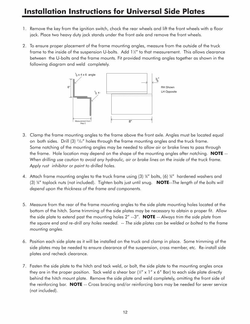
1. Remove the key from the ignition switch, chock the rear wheels and lift the front wheels with a floor jack. Place two heavy duty jack stands under the front axle and remove the front wheels. 2. To ensure proper placement of the frame mounting angles, measure from the outside of the truck frame to the inside of the suspension U-bolts. Add 11⁄2” to that measurement. This allows clearance between the U-bolts and the frame mounts. Fit provided mounting angles together as shown in the following diagram and weld completely.
3. Clamp the frame mounting angles to the frame above the front axle. Angles must be located equal on both sides. Drill (3) 21⁄32” holes through the frame mounting angles and the truck frame. Some notching of the mounting angles may be needed to allow air or brake lines to pass through the frame. Hole location may depend on the shape of the mounting angles after notching. NOTE -- When drilling use caution to avoid any hydraulic, air or brake lines on the inside of the truck frame. Apply rust inhibitor or paint to drilled holes. 4. Attach frame mounting angles to the truck frame using (3) 5⁄8” bolts, (6) 5⁄8” hardened washers and (3) 5⁄8” toplock nuts (not included). Tighten bolts just until snug. NOTE--The length of the bolts will depend upon the thickness of the frame and components.
5. Measure from the rear of the frame mounting angles to the side plate mounting holes located at the bottom of the hitch. Some trimming of the side plates may be necessary to obtain a proper fit. Allow the side plate to extend past the mounting holes 2” --3”. NOTE -- Always trim the side plate from the square end and re-drill any holes needed. -- The side plates can be welded or bolted to the frame mounting angles. 6. Position each side plate as it will be installed on the truck and clamp in place. Some trimming of the side plates may be needed to ensure clearance of the suspension, cross member, etc. Re-install side plates and recheck clearance. 7. Fasten the side plate to the hitch and tack weld, or bolt, the side plate to the mounting angles once they are in the proper position. Tack weld a shear bar (1⁄2” x 1” x 6” Bar) to each side plate directly behind the hitch mount plate. Remove the side plate and weld completely, omitting the front side of the reinforcing bar. NOTE -- Cross bracing and/or reinforcing bars may be needed for sever service (not included).
Measurement from Step 2
6"
x 4 x 6 angle1/2
x 4 1/2
8"
3/4"
RH ShownLH Opposite
Installation Instructions for Universal Side Plates

13
8. Touch up the side plate with paint and re-install on the truck. Tighten all bolts to specifications. 9. Side plates that are designed to attach to the outside of the truck frame are bolted directly to the hitch and truck frame. Some notching of the plates may be necessary to avoid the truck suspension or any components already attached to the truck frame. NOTE -- Cross bracing and/or reinforcing bars may be needed for severe service (not included).
10. Clamp side plates in place and drill holes as needed. Note - Apply rust inhibitor or paint to drilled holes. 11. Tighten all bolts to specifications.
12. Put the wheels back on the truck, remove the jack stands and the rear wheel chocks. Torque to spec.
ShearBar
Welded together, canbe welded or bolted to side plate.
(May require notching, trimming)
(Not notched or drilled at factory. May vary according to application.)
Mounting angle3/8 x 4 x 6 x 37 L
ShearBar
Installation Instructions for Universal Side Plates
14
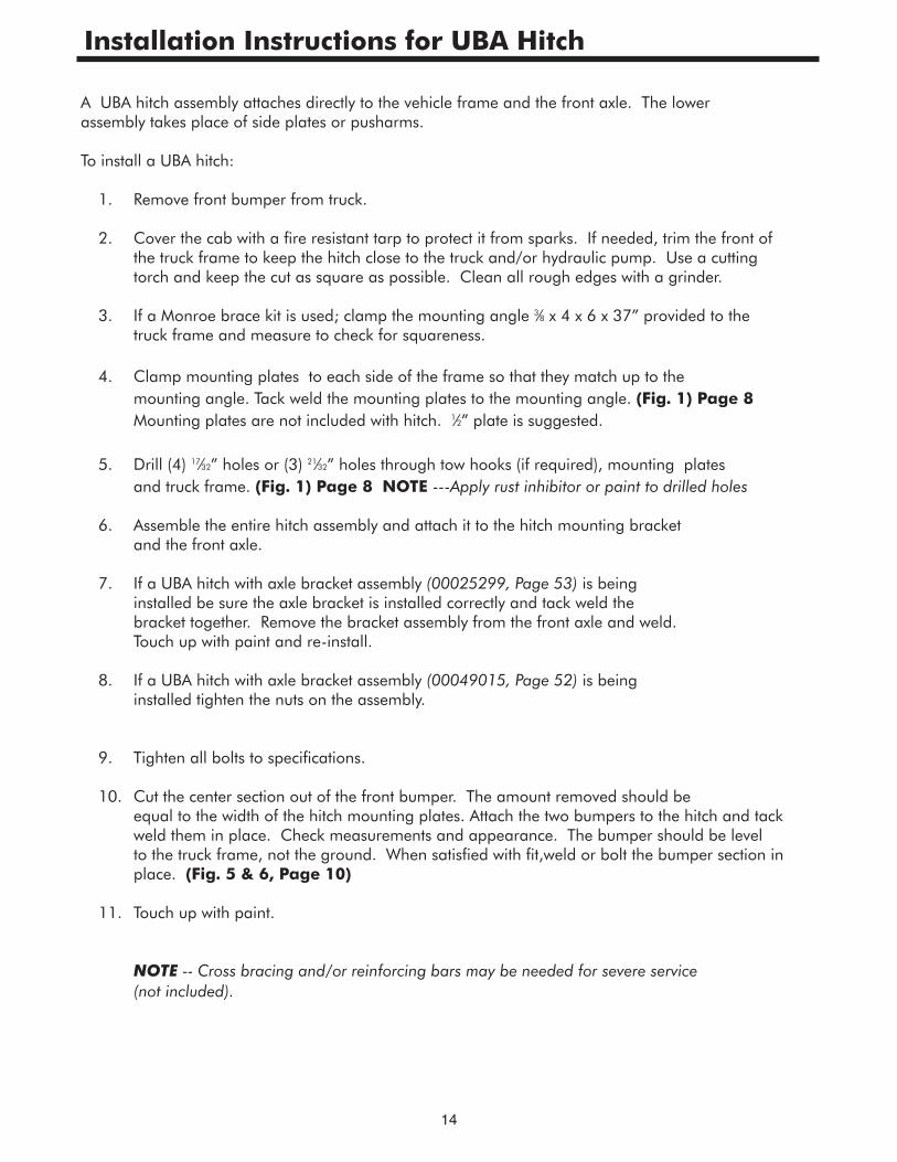
A UBA hitch assembly attaches directly to the vehicle frame and the front axle. The lower assembly takes place of side plates or pusharms.
To install a UBA hitch: 1. Remove front bumper from truck. 2. Cover the cab with a fire resistant tarp to protect it from sparks. If needed, trim the front of the truck frame to keep the hitch close to the truck and/or hydraulic pump. Use a cutting torch and keep the cut as square as possible. Clean all rough edges with a grinder.
3. If a Monroe brace kit is used; clamp the mounting angle 3⁄8 x 4 x 6 x 37” provided to the truck frame and measure to check for squareness. 4. Clamp mounting plates to each side of the frame so that they match up to the mounting angle. Tack weld the mounting plates to the mounting angle. (Fig. 1) Page 8 Mounting plates are not included with hitch. 1⁄2” plate is suggested. 5. Drill (4) 17⁄32” holes or (3) 21⁄32” holes through tow hooks (if required), mounting plates and truck frame. (Fig. 1) Page 8 NOTE ---Apply rust inhibitor or paint to drilled holes 6. Assemble the entire hitch assembly and attach it to the hitch mounting bracket and the front axle. 7. If a UBA hitch with axle bracket assembly (00025299, Page 53) is being installed be sure the axle bracket is installed correctly and tack weld the bracket together. Remove the bracket assembly from the front axle and weld. Touch up with paint and re-install.
8. If a UBA hitch with axle bracket assembly (00049015, Page 52) is being installed tighten the nuts on the assembly.
9. Tighten all bolts to specifications.
10. Cut the center section out of the front bumper. The amount removed should be equal to the width of the hitch mounting plates. Attach the two bumpers to the hitch and tack weld them in place. Check measurements and appearance. The bumper should be level to the truck frame, not the ground. When satisfied with fit,weld or bolt the bumper section in place. (Fig. 5 & 6, Page 10)
11. Touch up with paint.
NOTE -- Cross bracing and/or reinforcing bars may be needed for severe service (not included).
Installation Instructions for UBA Hitch
15
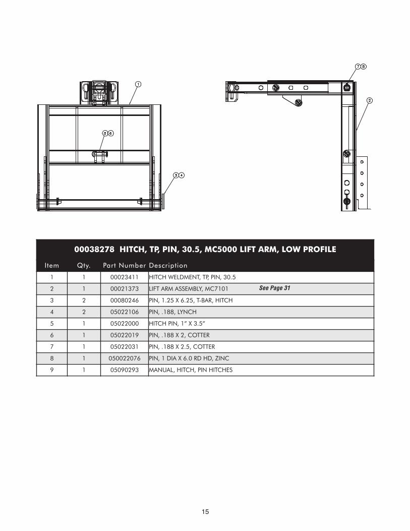
00038278 HITCH, TP, PIN, 30.5, MC5000 LIFT ARM, LOW PROFILE
Item Qty. Part Number Description
1 1 00023411 HITCH WELDMENT, TP, PIN, 30.5
2 1 00021373 LIFT ARM ASSEMBLY, MC7101
3 2 00080246 PIN, 1.25 X 6.25, T-BAR, HITCH
4 2 05022106 PIN, .188, LYNCH
5 1 05022000 HITCH PIN, 1” X 3.5”
6 1 05022019 PIN, .188 X 2, COTTER
7 1 05022031 PIN, .188 X 2.5, COTTER
8 1 050022076 PIN, 1 DIA X 6.0 RD HD, ZINC
9 1 05090293 MANUAL, HITCH, PIN HITCHES
See Page 31
16
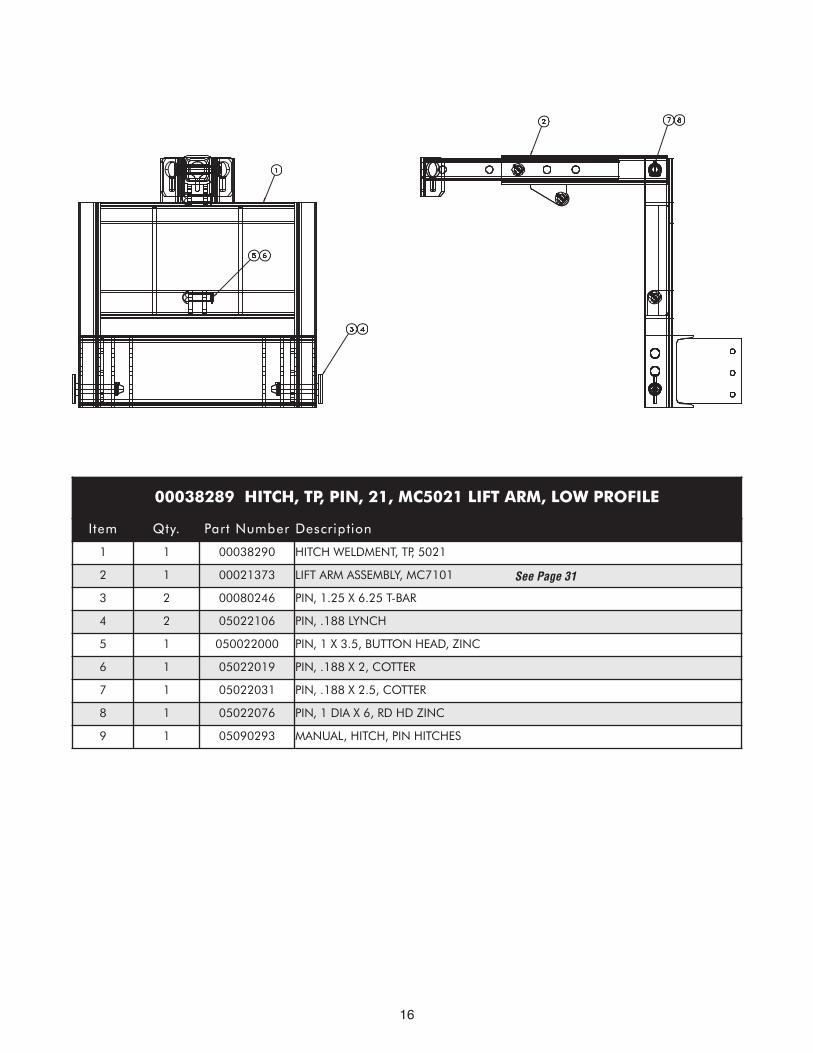
00038289 HITCH, TP, PIN, 21, MC5021 LIFT ARM, LOW PROFILE
Item Qty. Part Number Description
1 1 00038290 HITCH WELDMENT, TP, 5021
2 1 00021373 LIFT ARM ASSEMBLY, MC7101
3 2 00080246 PIN, 1.25 X 6.25 T-BAR
4 2 05022106 PIN, .188 LYNCH
5 1 050022000 PIN, 1 X 3.5, BUTTON HEAD, ZINC
6 1 05022019 PIN, .188 X 2, COTTER
7 1 05022031 PIN, .188 X 2.5, COTTER
8 1 05022076 PIN, 1 DIA X 6, RD HD ZINC
9 1 05090293 MANUAL, HITCH, PIN HITCHES
See Page 31
17
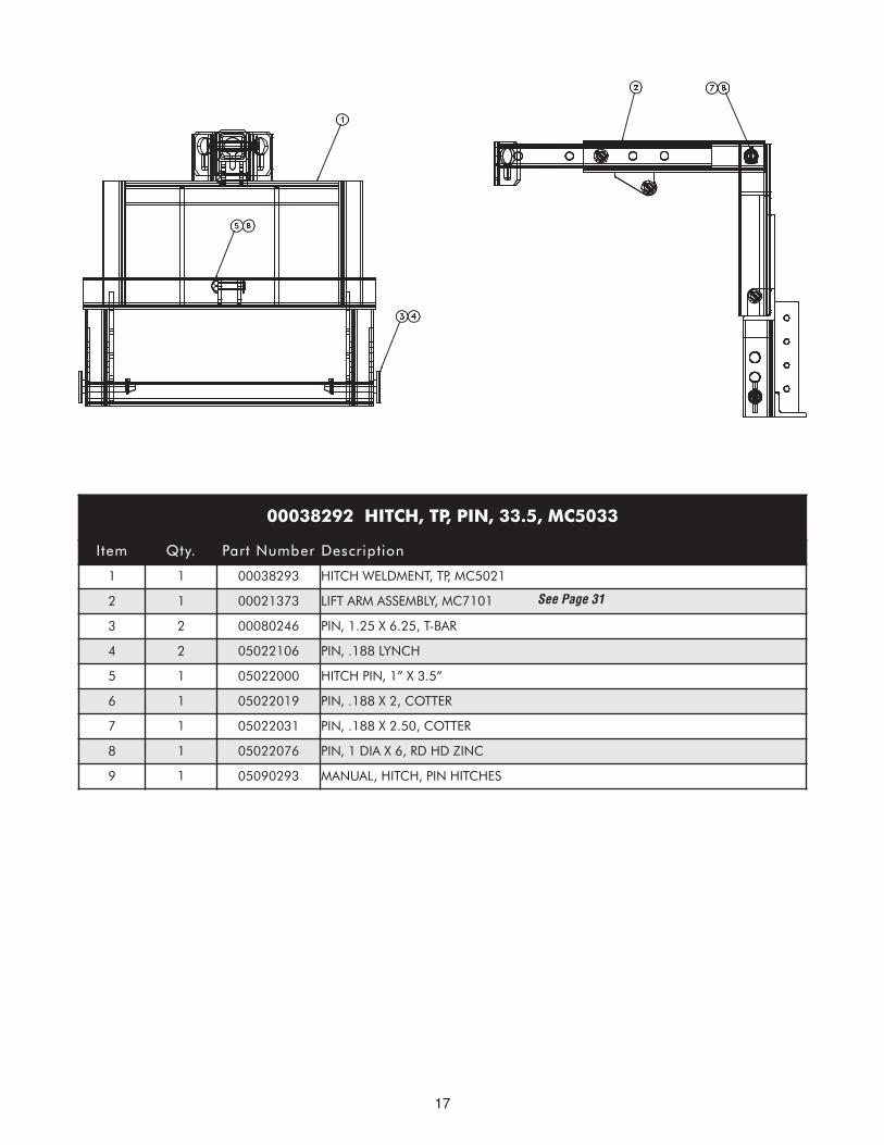
00038292 HITCH, TP, PIN, 33.5, MC5033
Item Qty. Part Number Description
1 1 00038293 HITCH WELDMENT, TP, MC5021
2 1 00021373 LIFT ARM ASSEMBLY, MC7101
3 2 00080246 PIN, 1.25 X 6.25, T-BAR
4 2 05022106 PIN, .188 LYNCH
5 1 05022000 HITCH PIN, 1” X 3.5”
6 1 05022019 PIN, .188 X 2, COTTER
7 1 05022031 PIN, .188 X 2.50, COTTER
8 1 05022076 PIN, 1 DIA X 6, RD HD ZINC
9 1 05090293 MANUAL, HITCH, PIN HITCHES
See Page 31
18
1011
2
45
67
59
3
1213
1
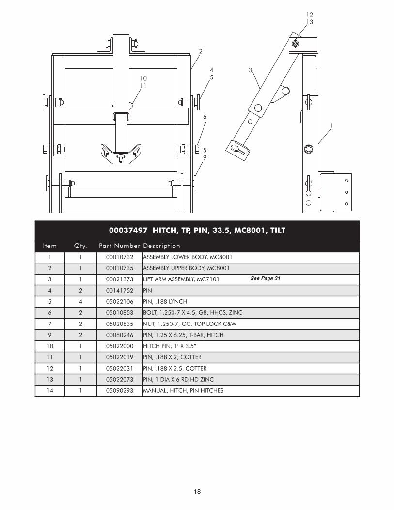
00037497 HITCH, TP, PIN, 33.5, MC8001, TILT
Item Qty. Part Number Description
1 1 00010732 ASSEMBLY LOWER BODY, MC8001
2 1 00010735 ASSEMBLY UPPER BODY, MC8001
3 1 00021373 LIFT ARM ASSEMBLY, MC7101
4 2 00141752 PIN
5 4 05022106 PIN, .188 LYNCH
6 2 05010853 BOLT, 1.250-7 X 4.5, G8, HHCS, ZINC
7 2 05020835 NUT, 1.250-7, GC, TOP LOCK C&W
9 2 00080246 PIN, 1.25 X 6.25, T-BAR, HITCH
10 1 05022000 HITCH PIN, 1’ X 3.5”
11 1 05022019 PIN, .188 X 2, COTTER
12 1 05022031 PIN, .188 X 2.5, COTTER
13 1 05022073 PIN, 1 DIA X 6 RD HD ZINC
14 1 05090293 MANUAL, HITCH, PIN HITCHES
See Page 31
19
3
1112
910
2
45
67
1
85
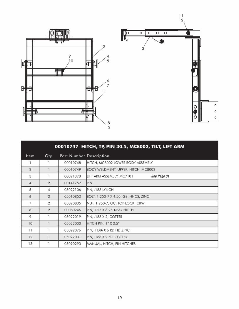
00010747 HITCH, TP, PIN 30.5, MC8002, TILT, LIFT ARM
Item Qty. Part Number Description
1 1 00010748 HITCH, MC8002 LOWER BODY ASSEMBLY
2 1 00010749 BODY WELDMENT, UPPER, HITCH, MC8002
3 1 00021373 LIFT ARM ASSEMBLY, MC7101
4 2 00141752 PIN
5 4 05022106 PIN, .188 LYNCH
6 2 05010853 BOLT, 1.250-7 X 4.50, G8, HHCS, ZINC
7 2 05020835 NUT, 1.250-7, GC, TOP LOCK, C&W
8 2 00080246 PIN, 1.25 X 6.25 T-BAR HITCH
9 1 05022019 PIN, .188 X 2, COTTER
10 1 05022000 HITCH PIN, 1” X 3.5”
11 1 05022076 PIN, 1 DIA X 6 RD HD ZINC
12 1 05022031 PIN, .188 X 2.50, COTTER
13 1 05090293 MANUAL, HITCH, PIN HITCHES
See Page 31
20
1
45
1112
2
67
58
3910
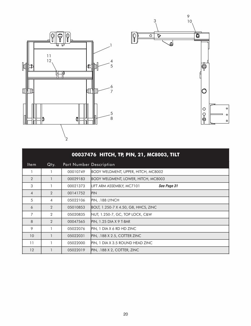
00037476 HITCH, TP, PIN, 21, MC8003, TILT
Item Qty. Part Number Description
1 1 00010749 BODY WELDMENT, UPPER, HITCH, MC8002
2 1 00029183 BODY WELDMENT, LOWER, HITCH, MC8003
3 1 00021373 LIFT ARM ASSEMBLY, MC7101
4 2 00141752 PIN
5 4 05022106 PIN, .188 LYNCH
6 2 05010853 BOLT, 1.250-7 X 4.50, G8, HHCS, ZINC
7 2 05020835 NUT, 1.250-7, GC, TOP LOCK, C&W
8 2 00047565 PIN, 1.25 DIA X 9 T-BAR
9 1 05022076 PIN, 1 DIA X 6 RD HD ZINC
10 1 05022031 PIN, .188 X 2.5, COTTER ZINC
11 1 05022000 PIN, 1 DIA X 3.5 ROUND HEAD ZINC
12 1 05022019 PIN, .188 X 2, COTTER, ZINC
See Page 31
21
22
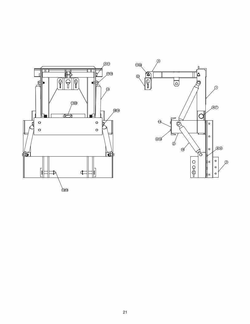
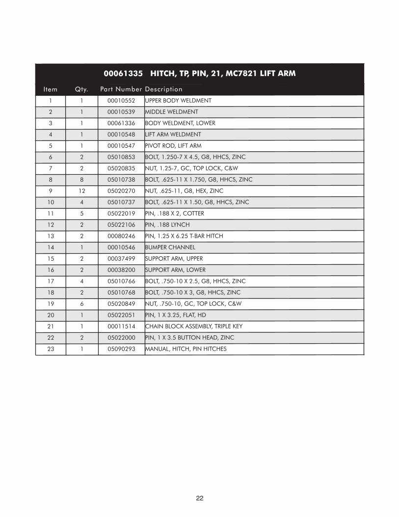
00061335 HITCH, TP, PIN, 21, MC7821 LIFT ARM
Item Qty. Part Number Description
1 1 00010552 UPPER BODY WELDMENT
2 1 00010539 MIDDLE WELDMENT
3 1 00061336 BODY WELDMENT, LOWER
4 1 00010548 LIFT ARM WELDMENT
5 1 00010547 PIVOT ROD, LIFT ARM
6 2 05010853 BOLT, 1.250-7 X 4.5, G8, HHCS, ZINC
7 2 05020835 NUT, 1.25-7, GC, TOP LOCK, C&W
8 8 05010738 BOLT, .625-11 X 1.750, G8, HHCS, ZINC
9 12 05020270 NUT, .625-11, G8, HEX, ZINC
10 4 05010737 BOLT, .625-11 X 1.50, G8, HHCS, ZINC
11 5 05022019 PIN, .188 X 2, COTTER
12 2 05022106 PIN, .188 LYNCH
13 2 00080246 PIN, 1.25 X 6.25 T-BAR HITCH
14 1 00010546 BUMPER CHANNEL
15 2 00037499 SUPPORT ARM, UPPER
16 2 00038200 SUPPORT ARM, LOWER
17 4 05010766 BOLT, .750-10 X 2.5, G8, HHCS, ZINC
18 2 05010768 BOLT, .750-10 X 3, G8, HHCS, ZINC
19 6 05020849 NUT, .750-10, GC, TOP LOCK, C&W
20 1 05022051 PIN, 1 X 3.25, FLAT, HD
21 1 00011514 CHAIN BLOCK ASSEMBLY, TRIPLE KEY
22 2 05022000 PIN, 1 X 3.5 BUTTON HEAD, ZINC
23 1 05090293 MANUAL, HITCH, PIN HITCHES
23
24
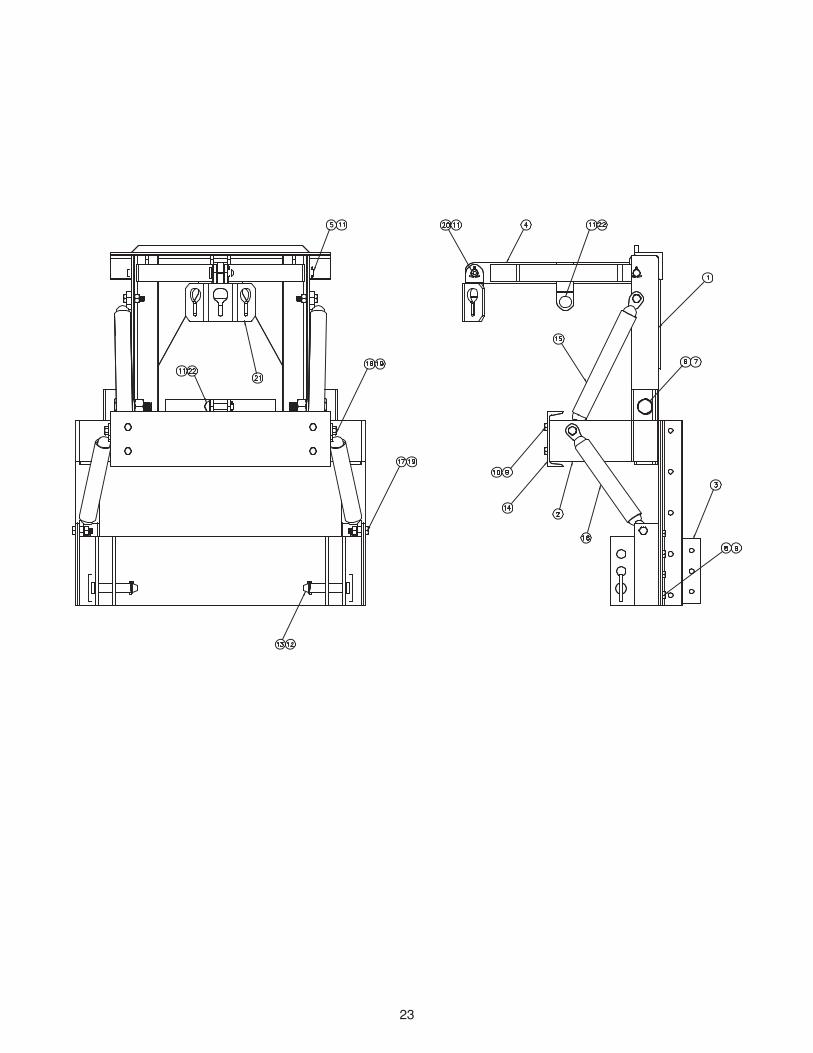
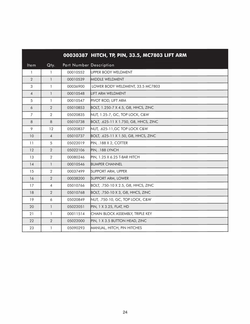
00030387 HITCH, TP, PIN, 33.5, MC7803 LIFT ARM
I tem Qty. Part Number Descript ion
1 1 00010552 UPPER BODY WELDMENT
2 1 00010539 MIDDLE WELDMENT
3 1 00036900 LOWER BODY WELDMENT, 33.5 MC7803
4 1 00010548 LIFT ARM WELDMENT
5 1 00010547 PIVOT ROD, LIFT ARM
6 2 05010853 BOLT, 1.250-7 X 4.5, G8, HHCS, ZINC
7 2 05020835 NUT, 1.25-7, GC, TOP LOCK, C&W
8 8 05010738 BOLT, .625-11 X 1.750, G8, HHCS, ZINC
9 12 05020837 NUT, .625-11,GC TOP LOCK C&W
10 4 05010737 BOLT, .625-11 X 1.50, G8, HHCS, ZINC
11 5 05022019 PIN, .188 X 2, COTTER
12 2 05022106 PIN, .188 LYNCH
13 2 00080246 PIN, 1.25 X 6.25 T-BAR HITCH
14 1 00010546 BUMPER CHANNEL
15 2 00037499 SUPPORT ARM, UPPER
16 2 00038200 SUPPORT ARM, LOWER
17 4 05010766 BOLT, .750-10 X 2.5, G8, HHCS, ZINC
18 2 05010768 BOLT, .750-10 X 3, G8, HHCS, ZINC
19 6 05020849 NUT, .750-10, GC, TOP LOCK, C&W
20 1 05022051 PIN, 1 X 3.25, FLAT, HD
21 1 00011514 CHAIN BLOCK ASSEMBLY, TRIPLE KEY
22 2 05022000 PIN, 1 X 3.5 BUTTON HEAD, ZINC
23 1 05090293 MANUAL, HITCH, PIN HITCHES
25
13 12
212011 4
1410 9 2
16
398
76
1
18 19
15
2211
17 19
5 11
26
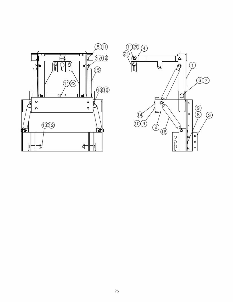
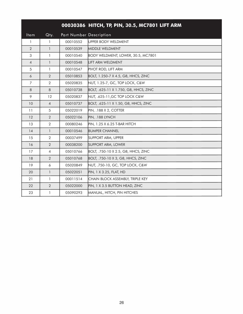
00030386 HITCH, TP, PIN, 30.5, MC7801 LIFT ARM
I tem Qty. Part Number Descript ion
1 1 00010552 UPPER BODY WELDMENT
2 1 00010539 MIDDLE WELDMENT
3 1 00010540 BODY WELDMENT, LOWER, 30.5, MC7801
4 1 00010548 LIFT ARM WELDMENT
5 1 00010547 PIVOT ROD, LIFT ARM
6 2 05010853 BOLT, 1.250-7 X 4.5, G8, HHCS, ZINC
7 2 05020835 NUT, 1.25-7, GC, TOP LOCK, C&W
8 8 05010738 BOLT, .625-11 X 1.750, G8, HHCS, ZINC
9 12 05020837 NUT, .625-11,GC TOP LOCK C&W
10 4 05010737 BOLT, .625-11 X 1.50, G8, HHCS, ZINC
11 5 05022019 PIN, .188 X 2, COTTER
12 2 05022106 PIN, .188 LYNCH
13 2 00080246 PIN, 1.25 X 6.25 T-BAR HITCH
14 1 00010546 BUMPER CHANNEL
15 2 00037499 SUPPORT ARM, UPPER
16 2 00038200 SUPPORT ARM, LOWER
17 4 05010766 BOLT, .750-10 X 2.5, G8, HHCS, ZINC
18 2 05010768 BOLT, .750-10 X 3, G8, HHCS, ZINC
19 6 05020849 NUT, .750-10, GC, TOP LOCK, C&W
20 1 05022051 PIN, 1 X 3.25, FLAT, HD
21 1 00011514 CHAIN BLOCK ASSEMBLY, TRIPLE KEY
22 2 05022000 PIN, 1 X 3.5 BUTTON HEAD, ZINC
23 1 05090293 MANUAL, HITCH, PIN HITCHES
27
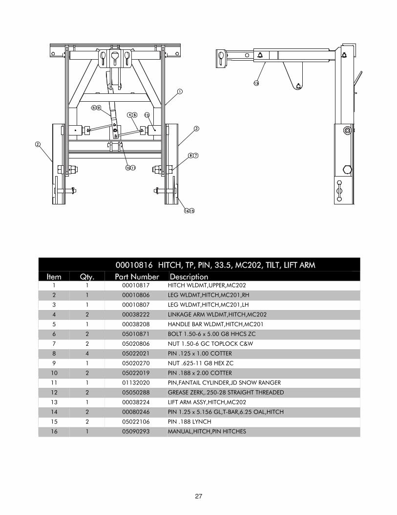
Item Qty. Part Number Description00010816 HITCH, TP, PIN, 33.5, MC202, TILT, LIFT ARM
1 1 00010817 HITCH WLDMT,UPPER,MC202
2 1 00010806 LEG WLDMT,HITCH,MC201,RH
3 1 00010807 LEG WLDMT,HITCH,MC201,LH
4 2 00038222 LINKAGE ARM WLDMT,HITCH,MC202
5 1 00038208 HANDLE BAR WLDMT,HITCH,MC201
6 2 05010871 BOLT 1.50-6 x 5.00 G8 HHCS ZC
7 2 05020806 NUT 1.50-6 GC TOPLOCK C&W
8 4 05022021 PIN .125 x 1.00 COTTER
9 1 05020270 NUT .625-11 G8 HEX ZC
10 2 05022019 PIN .188 x 2.00 COTTER
11 1 01132020 PIN,FANTAIL CYLINDER,JD SNOW RANGER
12 2 05050288 GREASE ZERK,.250-28 STRAIGHT THREADED
13 1 00038224 LIFT ARM ASSY,HITCH,MC202
14 2 00080246 PIN 1.25 x 5.156 GL,T-BAR,6.25 OAL,HITCH
15 2 05022106 PIN .188 LYNCH
16 1 05090293 MANUAL,HITCH,PIN HITCHES
28
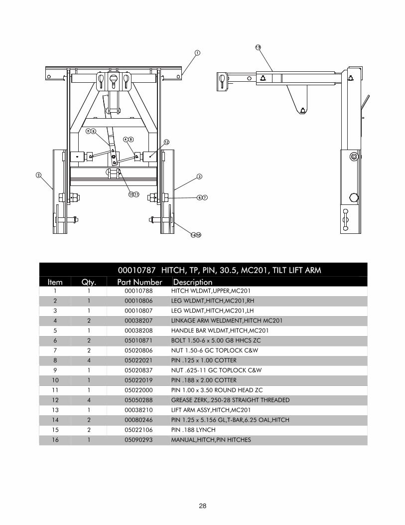
IItteemm QQttyy.. PPaarrtt NNuummbbeerr DDeessccrriippttiioonn0000001100778877 HHIITTCCHH,, TTPP,, PPIINN,, 3300..55,, MMCC220011,, TTIILLTT LLIIFFTT AARRMM
1 1 00010788 HITCH WLDMT,UPPER,MC201
2 1 00010806 LEG WLDMT,HITCH,MC201,RH
3 1 00010807 LEG WLDMT,HITCH,MC201,LH
4 2 00038207 LINKAGE ARM WELDMENT,HITCH MC201
5 1 00038208 HANDLE BAR WLDMT,HITCH,MC201
6 2 05010871 BOLT 1.50-6 x 5.00 G8 HHCS ZC
7 2 05020806 NUT 1.50-6 GC TOPLOCK C&W
8 4 05022021 PIN .125 x 1.00 COTTER
9 1 05020837 NUT .625-11 GC TOPLOCK C&W
10 1 05022019 PIN .188 x 2.00 COTTER
11 1 05022000 PIN 1.00 x 3.50 ROUND HEAD ZC
12 4 05050288 GREASE ZERK,.250-28 STRAIGHT THREADED
13 1 00038210 LIFT ARM ASSY,HITCH,MC201
14 2 00080246 PIN 1.25 x 5.156 GL,T-BAR,6.25 OAL,HITCH
15 2 05022106 PIN .188 LYNCH
16 1 05090293 MANUAL,HITCH,PIN HITCHES
29
30
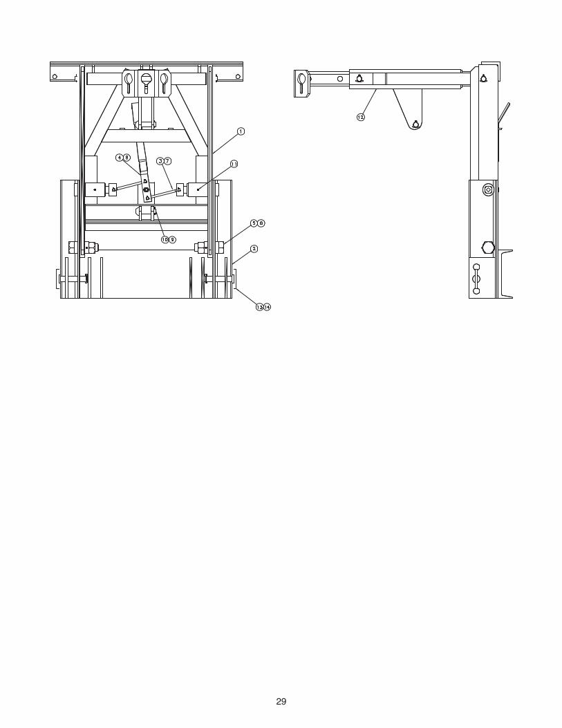
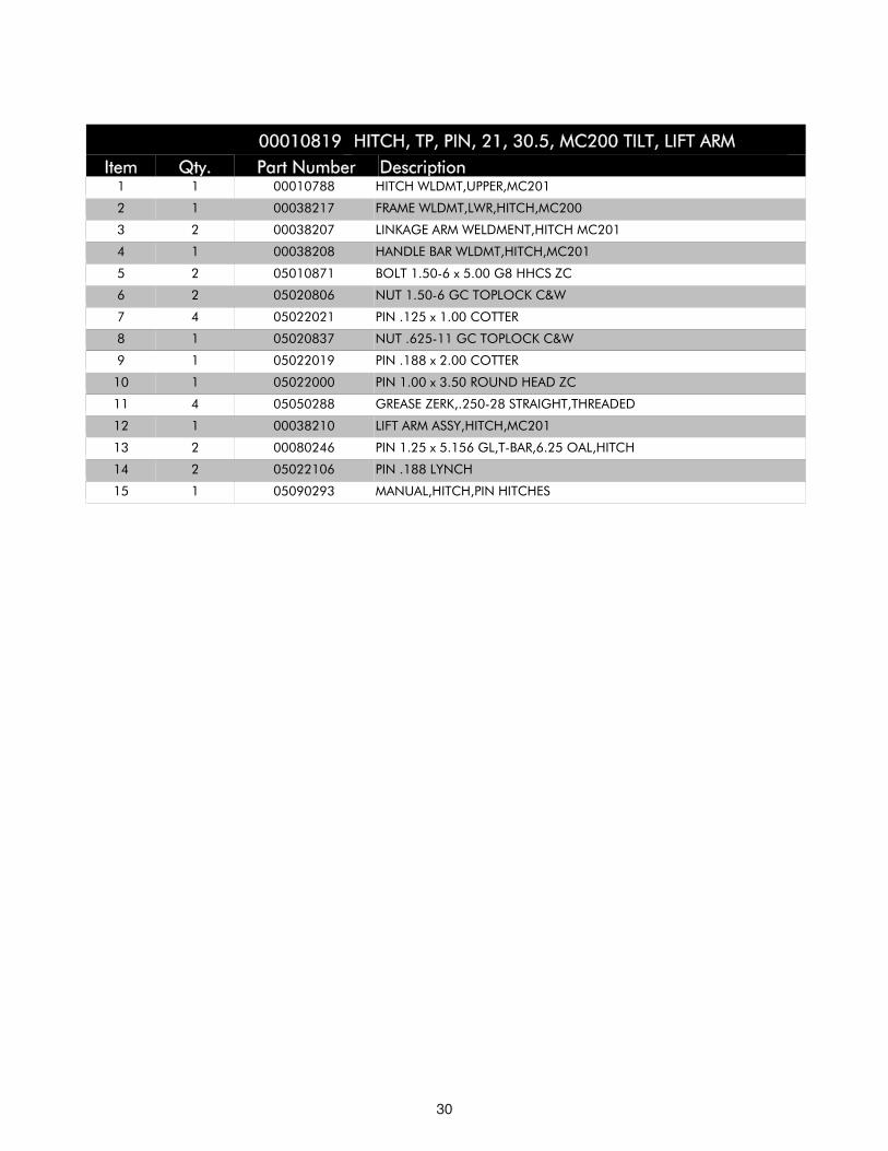
IItteemm QQttyy.. PPaarrtt NNuummbbeerr DDeessccrriippttiioonn0000001100881199 HHIITTCCHH,, TTPP,, PPIINN,, 2211,, 3300..55,, MMCC220000 TTIILLTT,, LLIIFFTT AARRMM
1 1 00010788 HITCH WLDMT,UPPER,MC201
2 1 00038217 FRAME WLDMT,LWR,HITCH,MC200
3 2 00038207 LINKAGE ARM WELDMENT,HITCH MC201
4 1 00038208 HANDLE BAR WLDMT,HITCH,MC201
5 2 05010871 BOLT 1.50-6 x 5.00 G8 HHCS ZC
6 2 05020806 NUT 1.50-6 GC TOPLOCK C&W
7 4 05022021 PIN .125 x 1.00 COTTER
8 1 05020837 NUT .625-11 GC TOPLOCK C&W
9 1 05022019 PIN .188 x 2.00 COTTER
10 1 05022000 PIN 1.00 x 3.50 ROUND HEAD ZC
11 4 05050288 GREASE ZERK,.250-28 STRAIGHT,THREADED
12 1 00038210 LIFT ARM ASSY,HITCH,MC201
13 2 00080246 PIN 1.25 x 5.156 GL,T-BAR,6.25 OAL,HITCH
14 2 05022106 PIN .188 LYNCH
15 1 05090293 MANUAL,HITCH,PIN HITCHES

31
32
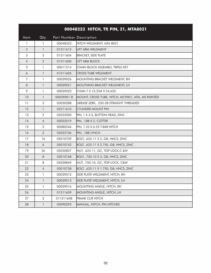
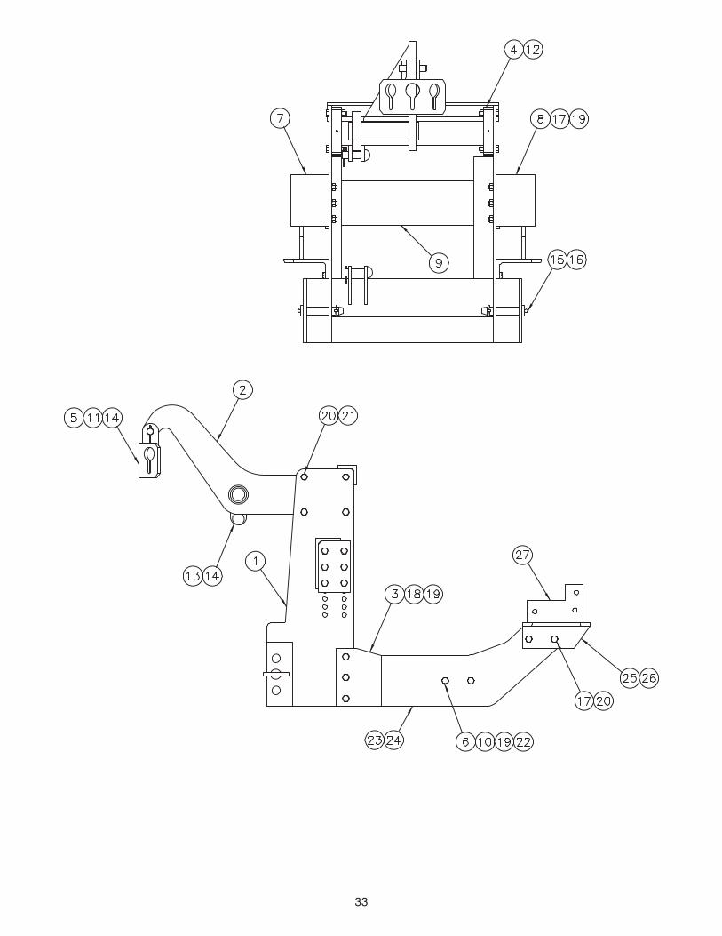
00048223 HITCH, TP, PIN, 21, MTA8021
Item Qty. Part Number Description
1 1 00048323 HITCH WELDMENT, MTA 8021
2 1 01311612 LIFT ARM WELDMENT
3 2 01311604 BRACKET, SIDE PLATE
4 2 01311600 LIFT ARM BLOCK
5 1 00011514 CHAIN BLOCK ASSEMBLY, TRIPLE KEY
6 1 01311605 CROSS TUBE WELDMENT
7 1 00039026 MOUNTING BRACKET WELDMENT, RH
8 1 00039021 MOUTNING BRACKET WELDMENT, LH
9 1 00039023 CHAN 7 X 12.25# X 24.625
10 1 00039001-B MOUNT, CROSS TUBE, HITCH, MC9001, MTA, MS PAINTED
11 2 05050288 GREASE ZERK, .250-28 STRAIGHT THREADED
12 1 02211610 CYLINDER MOUNT PIN
13 2 05022000 PIN, 1 X 3.5, BUTTON HEAD, ZINC
14 4 05022019 PIN, .188 X 2, COTTER
15 2 00080246 PIN, 1.25 X 6.25 T-BAR HITCH
16 2 05022106 PIN, .188 LYNCH
17 16 05010739 BOLT, .625-11 X 2, G8, HHCS, ZINC
18 6 05010742 BOLT, .625-11 X 2.750, G8, HHCS, ZINC
19 26 05020837 NUT, .625-11, GC, TOP LOCK,C &W
20 8 05010768 BOLT, .750-10 X 3, G8, HHCS, ZINC
21 8 05020849 NUT, .750-10, GC, TOP LOCK, C&W
22 4 05010738 BOLT, .625-11 X 1.750, G8, HHCS, ZINC
23 1 00039012 SIDE PLATE WELDMENT, HITCH, RH
24 1 00039013 SIDE PLATE WELDMENT, HITCH, LH
25 1 00039016 MOUNTING ANGLE, HITCH, RH
26 1 01311609 MOUNTING ANGLE, HITCH, LH
27 2 011311608 FRAME CLIP, HITCH
28 1 05090293 MANUAL, HITCH, PIN HITCHES
33
34
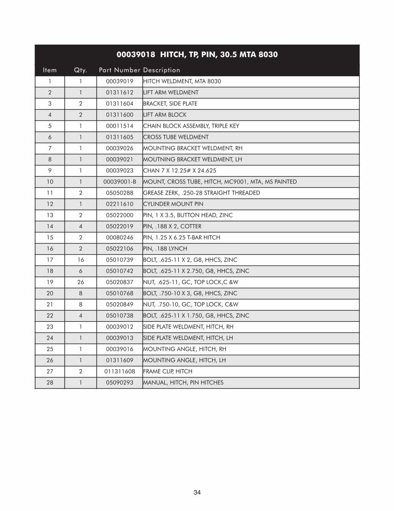
00039018 HITCH, TP, PIN, 30.5 MTA 8030
Item Qty. Part Number Description
1 1 00039019 HITCH WELDMENT, MTA 8030
2 1 01311612 LIFT ARM WELDMENT
3 2 01311604 BRACKET, SIDE PLATE
4 2 01311600 LIFT ARM BLOCK
5 1 00011514 CHAIN BLOCK ASSEMBLY, TRIPLE KEY
6 1 01311605 CROSS TUBE WELDMENT
7 1 00039026 MOUNTING BRACKET WELDMENT, RH
8 1 00039021 MOUTNING BRACKET WELDMENT, LH
9 1 00039023 CHAN 7 X 12.25# X 24.625
10 1 00039001-B MOUNT, CROSS TUBE, HITCH, MC9001, MTA, MS PAINTED
11 2 05050288 GREASE ZERK, .250-28 STRAIGHT THREADED
12 1 02211610 CYLINDER MOUNT PIN
13 2 05022000 PIN, 1 X 3.5, BUTTON HEAD, ZINC
14 4 05022019 PIN, .188 X 2, COTTER
15 2 00080246 PIN, 1.25 X 6.25 T-BAR HITCH
16 2 05022106 PIN, .188 LYNCH
17 16 05010739 BOLT, .625-11 X 2, G8, HHCS, ZINC
18 6 05010742 BOLT, .625-11 X 2.750, G8, HHCS, ZINC
19 26 05020837 NUT, .625-11, GC, TOP LOCK,C &W
20 8 05010768 BOLT, .750-10 X 3, G8, HHCS, ZINC
21 8 05020849 NUT, .750-10, GC, TOP LOCK, C&W
22 4 05010738 BOLT, .625-11 X 1.750, G8, HHCS, ZINC
23 1 00039012 SIDE PLATE WELDMENT, HITCH, RH
24 1 00039013 SIDE PLATE WELDMENT, HITCH, LH
25 1 00039016 MOUNTING ANGLE, HITCH, RH
26 1 01311609 MOUNTING ANGLE, HITCH, LH
27 2 011311608 FRAME CLIP, HITCH
28 1 05090293 MANUAL, HITCH, PIN HITCHES

35
36
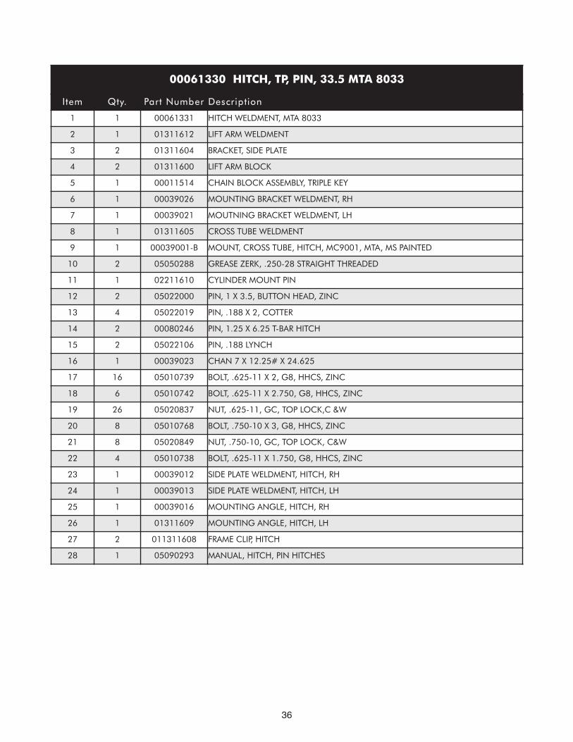
00061330 HITCH, TP, PIN, 33.5 MTA 8033
Item Qty. Part Number Description
1 1 00061331 HITCH WELDMENT, MTA 8033
2 1 01311612 LIFT ARM WELDMENT
3 2 01311604 BRACKET, SIDE PLATE
4 2 01311600 LIFT ARM BLOCK
5 1 00011514 CHAIN BLOCK ASSEMBLY, TRIPLE KEY
6 1 00039026 MOUNTING BRACKET WELDMENT, RH
7 1 00039021 MOUTNING BRACKET WELDMENT, LH
8 1 01311605 CROSS TUBE WELDMENT
9 1 00039001-B MOUNT, CROSS TUBE, HITCH, MC9001, MTA, MS PAINTED
10 2 05050288 GREASE ZERK, .250-28 STRAIGHT THREADED
11 1 02211610 CYLINDER MOUNT PIN
12 2 05022000 PIN, 1 X 3.5, BUTTON HEAD, ZINC
13 4 05022019 PIN, .188 X 2, COTTER
14 2 00080246 PIN, 1.25 X 6.25 T-BAR HITCH
15 2 05022106 PIN, .188 LYNCH
16 1 00039023 CHAN 7 X 12.25# X 24.625
17 16 05010739 BOLT, .625-11 X 2, G8, HHCS, ZINC
18 6 05010742 BOLT, .625-11 X 2.750, G8, HHCS, ZINC
19 26 05020837 NUT, .625-11, GC, TOP LOCK,C &W
20 8 05010768 BOLT, .750-10 X 3, G8, HHCS, ZINC
21 8 05020849 NUT, .750-10, GC, TOP LOCK, C&W
22 4 05010738 BOLT, .625-11 X 1.750, G8, HHCS, ZINC
23 1 00039012 SIDE PLATE WELDMENT, HITCH, RH
24 1 00039013 SIDE PLATE WELDMENT, HITCH, LH
25 1 00039016 MOUNTING ANGLE, HITCH, RH
26 1 01311609 MOUNTING ANGLE, HITCH, LH
27 2 011311608 FRAME CLIP, HITCH
28 1 05090293 MANUAL, HITCH, PIN HITCHES
37
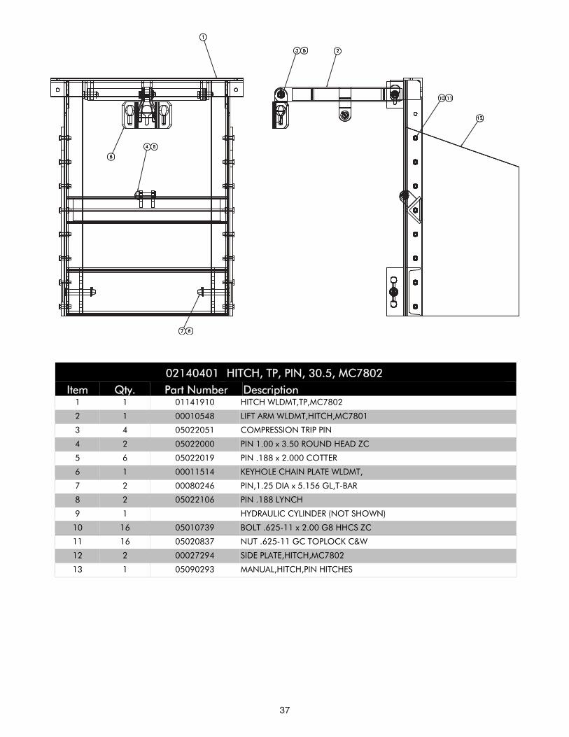
IItteemm QQttyy.. PPaarrtt NNuummbbeerr DDeessccrriippttiioonn0022114400440011 HHIITTCCHH,, TTPP,, PPIINN,, 3300..55,, MMCC77880022
1 1 01141910 HITCH WLDMT,TP,MC7802
2 1 00010548 LIFT ARM WLDMT,HITCH,MC7801
3 4 05022051 COMPRESSION TRIP PIN
4 2 05022000 PIN 1.00 x 3.50 ROUND HEAD ZC
5 6 05022019 PIN .188 x 2.000 COTTER
6 1 00011514 KEYHOLE CHAIN PLATE WLDMT,
7 2 00080246 PIN,1.25 DIA x 5.156 GL,T-BAR
8 2 05022106 PIN .188 LYNCH
9 1 HYDRAULIC CYLINDER (NOT SHOWN)
10 16 05010739 BOLT .625-11 x 2.00 G8 HHCS ZC
11 16 05020837 NUT .625-11 GC TOPLOCK C&W
12 2 00027294 SIDE PLATE,HITCH,MC7802
13 1 05090293 MANUAL,HITCH,PIN HITCHES
38
1 2 3 4
53
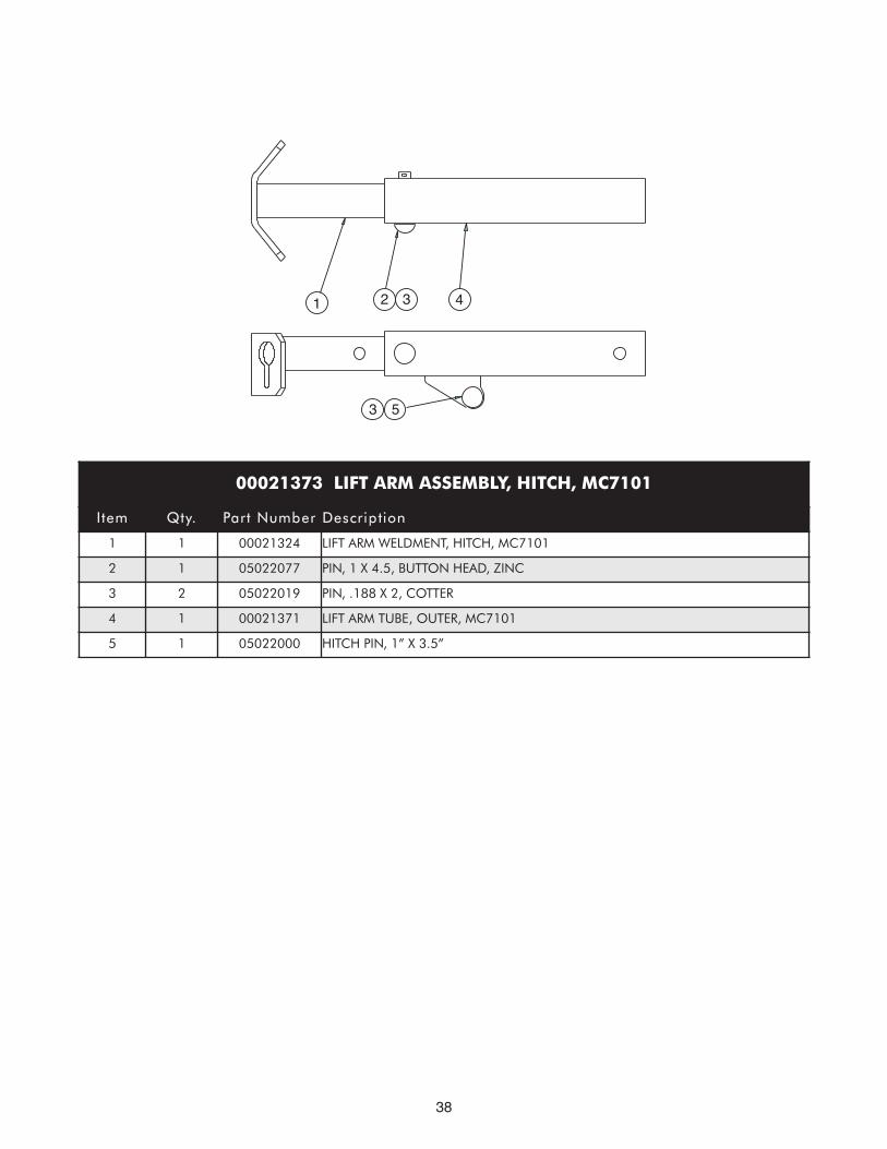
00021373 LIFT ARM ASSEMBLY, HITCH, MC7101
Item Qty. Part Number Description
1 1 00021324 LIFT ARM WELDMENT, HITCH, MC7101
2 1 05022077 PIN, 1 X 4.5, BUTTON HEAD, ZINC
3 2 05022019 PIN, .188 X 2, COTTER
4 1 00021371 LIFT ARM TUBE, OUTER, MC7101
5 1 05022000 HITCH PIN, 1” X 3.5”
39
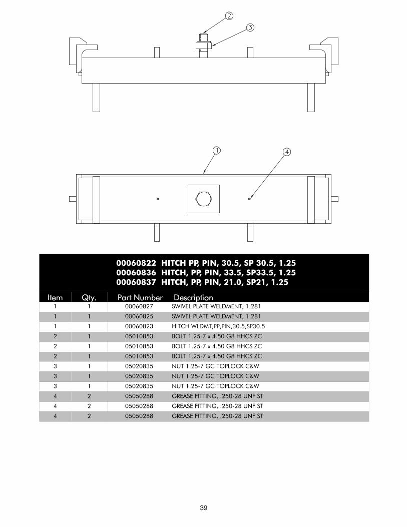
Item Qty. Part Number Description1 1 00060827 SWIVEL PLATE WELDMENT, 1.281
1 1 00060825 SWIVEL PLATE WELDMENT, 1.281
1 1 00060823 HITCH WLDMT,PP,PIN,30.5,SP30.5
2 1 05010853 BOLT 1.25-7 x 4.50 G8 HHCS ZC
2 1 05010853 BOLT 1.25-7 x 4.50 G8 HHCS ZC
2 1 05010853 BOLT 1.25-7 x 4.50 G8 HHCS ZC
3 1 05020835 NUT 1.25-7 GC TOPLOCK C&W
3 1 05020835 NUT 1.25-7 GC TOPLOCK C&W
3 1 05020835 NUT 1.25-7 GC TOPLOCK C&W
4 2 05050288 GREASE FITTING, .250-28 UNF ST
4 2 05050288 GREASE FITTING, .250-28 UNF ST
4 2 05050288 GREASE FITTING, .250-28 UNF ST
00060822 HITCH PP, PIN, 30.5, SP 30.5, 1.2500060836 HITCH, PP, PIN, 33.5, SP33.5, 1.2500060837 HITCH, PP, PIN, 21.0, SP21, 1.25
40
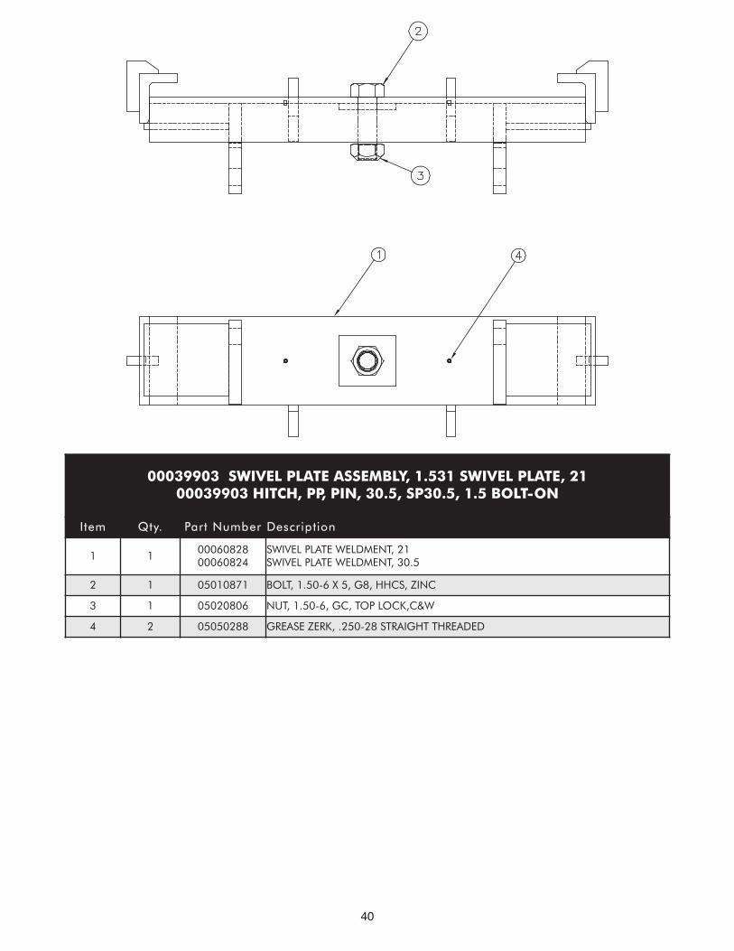
00039903 SWIVEL PLATE ASSEMBLY, 1.531 SWIVEL PLATE, 2100039903 HITCH, PP, PIN, 30.5, SP30.5, 1.5 BOLT-ON
Item Qty. Part Number Description
1 10006082800060824
SWIVEL PLATE WELDMENT, 21SWIVEL PLATE WELDMENT, 30.5
2 1 05010871 BOLT, 1.50-6 X 5, G8, HHCS, ZINC
3 1 05020806 NUT, 1.50-6, GC, TOP LOCK,C&W
4 2 05050288 GREASE ZERK, .250-28 STRAIGHT THREADED
41
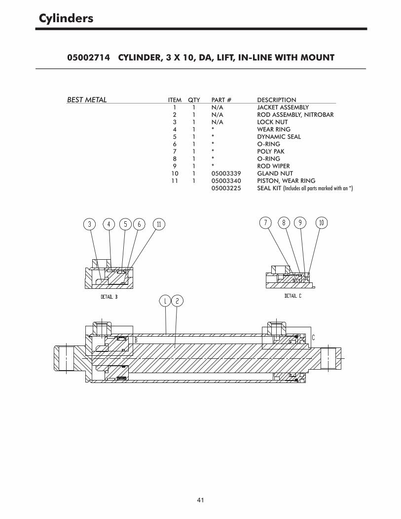
Cylinders
05002714 CYLINDER, 3 X 10, DA, LIFT, IN-LINE WITH MOUNT
ITEM1234567891011
QTY11111111111
PART #N/AN/AN/A******050033390500334005003225
DESCRIPTIONJACKET ASSEMBLYROD ASSEMBLY, NITROBARLOCK NUTWEAR RINGDYNAMIC SEALO-RINGPOLY PAKO-RINGROD WIPERGLAND NUTPISTON, WEAR RINGSEAL KIT (Includes all parts marked with an *)
BEST METAL
42
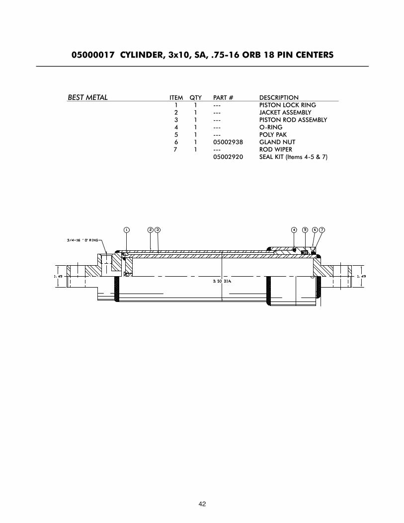
05000017 CYLINDER, 3x10, SA, .75-16 ORB 18 PIN CENTERS
ITEM1234567
QTY1111111
PART #---------------05002938---05002920
DESCRIPTIONPISTON LOCK RINGJACKET ASSEMBLYPISTON ROD ASSEMBLYO-RINGPOLY PAKGLAND NUTROD WIPERSEAL KIT (Items 4-5 & 7)
BEST METAL
43
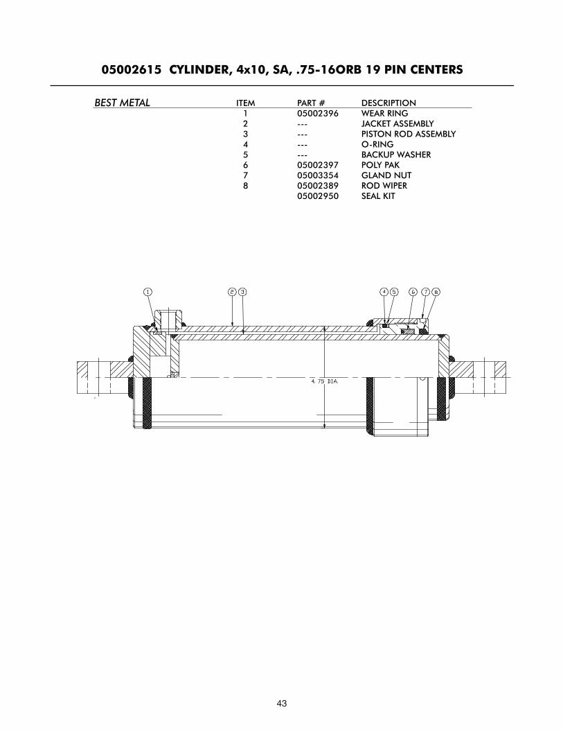
05002615 CYLINDER, 4x10, SA, .75-16ORB 19 PIN CENTERS
ITEM12345678
PART #05002396------------05002397050033540500238905002950
DESCRIPTIONWEAR RINGJACKET ASSEMBLYPISTON ROD ASSEMBLYO-RINGBACKUP WASHERPOLY PAKGLAND NUTROD WIPERSEAL KIT
BEST METAL

44
05002762 CYLINDER, 4x10, DA, NIT, .75 ORB, LIFT IN-LINE w/ PIN
ITEM123456789
QTY111112
------1
PART #---05000023------05000026---------05000021
DESCRIPTIONLOCK NUTPISTON UNICASE WELDMENTRODHEADPORT PLUGGREY PRIMERBLACK GLOSSSEAL KIT
BOBALEE
45
MONROE TRUCK EQUIPMENT, INC. WARRANTYSNOW & ICE CONTROL PRODUCTS
Monroe Truck Equipment, Inc. warrants to the original purchaser, that if anypart of the product proves to be defective in workmanship or material within ONEYEAR of the original installation, and is returned to us within 30 days of the discovered defect, we will (at our option) repair or replace the defective part.This warranty does not apply to damage resulting from misuse, neglect, accident, improper installation, normal wear items or lack of maintenance. Thiswarranty is exclusive and supersedes all other warranties, whether expressed or implied. Monroe Truck Equipment, Inc. neither assumes, norauthorizes anyone to assume for it, any other obligation or liability in connection with this warranty and will not be liable for consequential damages.
All engines, pumps, motors, cylinders and valves are warranted by their manufacturer and not by Monroe Truck Equipment, Inc.. The manufacturer'swarranty will apply to these parts. Electrical and hydraulic components are not tobe disassembled without the express written permission of Monroe Truck Equipment. Use of replacement parts other than original equipment voids thiswarranty.
All defective parts returned must be accompanied by the model number, serialnumber, date installed, date of defect, description of defect, and the name of thedistributor from whom it was purchased. All warranty claims must have prior written approval from Monroe Truck Equipment, Inc.
Please return the warranty registration card that accompanies this manual to confirm receipt of this parts catalog and acknowledge the information contained within. Failure to return the attached card may result in a voided warranty.
46
47