parts and maintenance manual for liftstar and … · parts and maintenance manual for...
TRANSCRIPT

PARTS AND MAINTENANCE MANUAL FOR
"LIFTSTAR" AND "PULLSTAR" AIR WINCH MODEL
LS1500R SERIES
READ THIS MANUAL BEFORE USING THESE PRODUCTS. This manual contains important maintenance information. Make this manual available to all persons responsible for the maintenance of these products.
Do not use this winch for lifting, supporting, or transporting people or lifting or supporting loads over people.
Always operate, inspect and maintain this winch in accordance with European Security Rules and any other applicable safety codes and regulations.
Refer all communications to the nearest INGERSOLL-RAND Material Handling Products Office or Distributor.
Form SAM0072 Edition 13 April 2012 38750436 2010 Ingersoll-Rand Company
2
TABLE OF CONTENTS
Description Page N°.
Installation and Operation ........................................................................................................................................... … Winch control.................................................................................................................................................................. ..…..3 Limit Switches ................................................................................................................................................................ ……3 Pneumatic Scheme .......................................................................................................................................................... ……3
Maintenance Maintenance Intervals................................................................................................................... ........................................... 4 General Disassembly . .............................................................................................................................................................. 5 Disassembly Instructions .......................................................................................................................................................... 5
Winch Disassembly ...................................................................................................................................................... 5 Lever Control Valve disassembly ................................................................................................................................. 6 Air Control Valve disassembly - Optional Europ Version ............................................................................................ 6 Air Gear Motor disassembly ......................................................................................................................................... 6 Pendant Control disassembly ........................................................................................................................................ 6 Shut-off valve disassembly ........................................................................................................................................... 7 Emergency stop valve disassembly ............................................................................................................................... 7
Cleaning, Inspection and Repair .............................................................................................................................................. 7 Assembly Instructions .............................................................................................................................................................. 7
Winch Assembly ........................................................................................................................................................... 7 Lever Control Valve Assembly ..................................................................................................................................... 8 Air Gear Motor Assembly............................................................................................................................................. 9 Pendant Control Assembly ............................................................................................................................................ 9 Pendant Control Adjustment ......................................................................................................................................... 9
Accessories .............................................................................................................................................................................. 10 Testing ..................................................................................................................................................................................... 10 Notes ........................................................................................................................................................................................ 11
Parts Winch Assembly Drawing ....................................................................................................................................................... 12 Winch Assembly Parts List ...................................................................................................................................................... 13 Air Gear Motor Assembly Drawing ......................................................................................................................................... 14 Air Gear Motor Assembly Part List ......................................................................................................................................... 15 “OLD” Lever Control Valve Assembly Drawing and Part List ............................................................................................... 16 Control Valve Assembly Drawing and Parts List ..................................................................................................................... 17 “NEW” Lever Control Valve Assembly Drawing .................................................................................................................... 18 “NEW” Lever Control Valve Assembly Part List .................................................................................................................... 19 Notes ........................................................................................................................................................................................ 20 Optional Valve Assembly Drawing and Parts List ................................................................................................................... 21 Two Pendant Control Assembly Drawing ................................................................................................................................ 22 Two Pendant Control Assembly Part List ................................................................................................................................ 23 Shu-off Valve Assembly Drawing and Parts List ..................................................................................................................... 24 Emergency Stop Valve Assembly Drawing and Parts List ....................................................................................................... 25 Torque Limitor Assembly Drawing and Parts List ................................................................................................................... 26 Limit Switches Assembly Drawing .......................................................................................................................................... 27-28 Limit Switches Assembly Parts Listing .................................................................................................................................... 29 Drum Guard Assembly Drawing and Parts List ....................................................................................................................... 30 Notes ........................................................................................................................................................................................ 31-33
Parts Ordering Information .................................................................................................................................................. 34 Warranty .................................................................................................................................................................................. 35 Office Location ........................................................................................................................................................................ 36
3
INSTALLATION & OPERATION
Winch Control
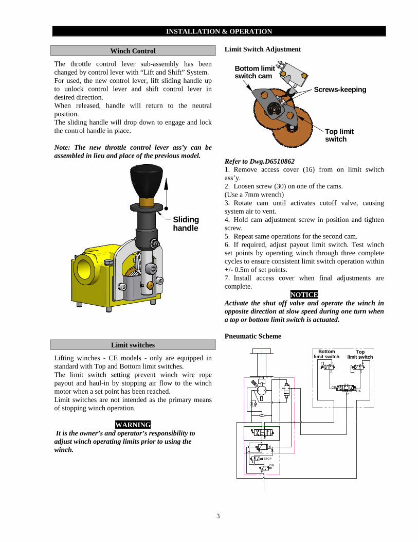
The throttle control lever sub-assembly has been changed by control lever with “Lift and Shift” System. For used, the new control lever, lift sliding handle up to unlock control lever and shift control lever in desired direction. When released, handle will return to the neutral position. The sliding handle will drop down to engage and lock the control handle in place. Note: The new throttle control lever ass’y can be assembled in lieu and place of the previous model.
Sliding handle
Limit switches
Lifting winches - CE models - only are equipped in standard with Top and Bottom limit switches. The limit switch setting prevent winch wire rope payout and haul-in by stopping air flow to the winch motor when a set point has been reached. Limit switches are not intended as the primary means of stopping winch operation.
WARNING It is the owner’s and operator’s responsibility to adjust winch operating limits prior to using the winch.
Limit Switch Adjustment
Bottom limitswitch cam
Screws-keeping
Top limitswitch
Refer to Dwg.D6510862 1. Remove access cover (16) from on limit switch ass’y. 2. Loosen screw (30) on one of the cams. (Use a 7mm wrench) 3. Rotate cam until activates cutoff valve, causing system air to vent. 4. Hold cam adjustment screw in position and tighten screw. 5. Repeat same operations for the second cam. 6. If required, adjust payout limit switch. Test winch set points by operating winch through three complete cycles to ensure consistent limit switch operation within +/- 0.5m of set points. 7. Install access cover when final adjustments are complete.
NOTICE Activate the shut off valve and operate the winch in opposite direction at slow speed during one turn when a top or bottom limit switch is actuated. Pneumatic Scheme
STOP
ON
EAEBP
BCB
A
CA
2
1
2
1
Bottomlimit switch
Toplimit switch
4
MAINTENANCE
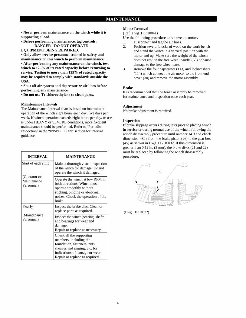
• Never perform maintenance on the winch while it is supporting a load. • Before performing maintenance, tag controls: DANGER - DO NOT OPERATE - EQUIPMENT BEING REPAIRED. • Only allow service personnel trained in safety and maintenance on this winch to perform maintenance. • After performing any maintenance on the winch, test winch to 125% of its rated capacity before returning to service. Testing to more than 125% of rated capacity may be required to comply with standards outside the USA. • Shut off air system and depressurize air lines before performing any maintenance. • Do not use Trichloroethylene to clean parts. Maintenance Intervals The Maintenance Interval chart is based on intermittent operation of the winch eight hours each day, five days per week. If winch operation exceeds eight hours per day, or use is under HEAVY or SEVERE conditions, more frequent maintenance should be performed. Refer to ‘Periodic Inspection’ in the “INSPECTION” section for interval guidance.
INTERVAL MAINTENANCECHECK
Start of each shift
(Operator orMaintenancePersonnel)
Make a thorough visual inspectionof the winch for damage. Do notoperate the winch if damaged.
Operate the winch at low RPM inboth directions. Winch mustoperate smoothly withoutsticking, binding or abnormalnoises. Check the operation of thebrake.
Yearly
(MaintenancePersonnel)
Inspect the brake disc. Clean orreplace parts as required.
Inspect the winch gearing, shaftsand bearings for wear anddamage.Repair or replace as necessary.
Check all the supportingmembers, including thefoundation, fasteners, nuts,sheaves and rigging, etc. forindications of damage or wear.Repair or replace as required.
Motor Removal (Ref. Dwg. D6310041) Use the following procedure to remove the motor. 1. Disconnect and tag the air lines. 2. Position several blocks of wood on the work bench
and stand the winch in a vertical position with the motor end up. Make sure the weight of the winch does not rest on the free wheel handle (65) or cause damage to the free wheel parts
3. Remove the four capscrews (113) and lockwashers (114) which connect the air motor to the front end cover (30) and remove the motor assembly.
Brake It is recommended that the brake assembly be removed for maintenance and inspection once each year. Adjustment No brake adjustment is required. Inspection If brake slippage occurs during tests prior to placing winch in service or during normal use of the winch, following the winch disassembly procedure until number 14.3 and check dimension « C » from the brake piston (26) to the gear box (45) as shown in Dwg. D6310032. If this dimension is greater than 0,12 in. (3 mm), the brake discs (21 and 22) must be replaced by following the winch disassembly procedure.
(Dwg. D6310032)
5
General Disassembly Procedures The following instructions provide the necessary information to disassemble, inspect, repair, and assemble the winch. Refer to the winch assembly drawing provided in the Parts Section.
If a winch is being completely disassembled for any reason, follow the order of the topics as they are presented. It is recommended that all maintenance work on the winch be performed on a bench in a clean dust free area. In the process of disassembling the winch, observe the following :
1. Never disassemble the winch any further than isnecessary to accomplish the needed repair. A good partcan be damaged during the course of disassembly.
2. Never use excessive force when removing parts.Tapping gently around the perimeter of a cover orhousing with a soft hammer, for example, is sufficientto break the seal.
3. Do not heat a part with a flame to free it for removal,unless the part being heated is already worn ordamaged beyond repair and no additional damage willoccur to other parts.
In general, the winch is designed to permit easy disassembly and assembly. The use of heat or excessive force should not be required.
4. Keep the work area as clean as practical, to preventdirt and other foreign matter from getting intobearings or other moving parts.
5. All seals and 'O' rings should be discarded once they have been removed. New seals and 'O' rings shouldbe used when assembling the winch.
6. When grasping a part in a vise, always use leather-covered or copper-covered vise jaws to protect thesurface of the part and help prevent distortion. This isparticularly true of threaded members and housings.
7. Do not remove any part which is press fit in or on asubassembly unless the removal of that part isnecessary for repairs or replacement.
8. When removing ball bearings from shafts, it is bestto use a bearing puller. When removing bearingsfrom housings, drive out the bearing with a sleeveslightly smaller than the outside diameter of thebearing. The end of the sleeve or pipe which contactsthe bearing must be square. Protect bearings fromdirt by keeping them wrapped in clean cloths
Disassembly Instructions Winch Disassembly (ref.Dwg.D6310041) 1. Disconnect and tag the air lines.2. Remove winch from its mounting and set in a clean
work area on a sturdy work bench.3. Position several blocks of wood on the work bench
and stand the winch in a vertical position with themotor end down.
4. Remove the nuts (2) and lock washers (3).5. Remove the rear end-cover (55).
5.1. Extract the exhaust washers (60) and the rings(59).
5.2. Pull bearing (58) from rear end cover (55) 6. Clutch control disassembly (PS SERIES)
6.1. Unscrew the handle (65) and pull the plunger (61) to remove clutch axle (66), clutch (72) and the spring (69).
6.2. If necessary remove retainer rings (62 and 63) to remove clutch (72) and bearing (71) from clutch axle (66)
6.3. Remove screws (67), washer (68), plunger body (70) and the plunger (61)
7. Remove the drum (56) from the winch.7.1. Remove the spacer (64).Only for PS series. 7.2. Remove the drum bushings (38) from the
drum (56) if they require replacement. 8. Remove the oil drain plug (6) and return the winch to
drain the oil from the gear casing. 9. Remove the four screws winch secure the motor (29)
to the front end cover (30) and pull off the motor straightaway from the winch. For disassembly of the motor and the valve, follow the corresponding procedure.
10. Remove the gasket (31) and the 'O'ring (27) anddrain the oil from the brake through the front end cover bore.
11. Remove the three nuts (2) and lock washers (3) andremove the three tie rod spacers (4).
12. Remove the output shaft (5) from the gearbox andbrake assembly.
13. Disassembly of the front end-cover (30).13.1. Remove the screws (34). 13.2. Remove the front end cover (30). 13.3. Remove the retainer ring (32). 13.4. Remove the oil seal (35).
NOTICE
• The oil seal has been installed with loctite ® 460 onthe backside of the seal.
14. Disassembly of the brake piston.14.1. Remove the O’ring (25) and the gasket (33).14.2. Remove the springs (41).14.3. Remove the bearing (36).14.4. Extract the brake piston (26) by using low
pressure compressed air in brake release port. 15. Disassembly of the gear box
15.1. Remove screws (47) and lock washers (48). 15.2. Extract the gear box cover by using jacking
screws in the two M4 threaded holes. 15.3. Press out the output shaft (5) and the output
annular gear (50). 15.4. Remove the bearings (51 and 53), oil seal (52)
and the O’ring (9). 15.5. Remove the bearing (10), spring washer (49)
and the output annular gear (50). 15.6. Remove the satellite support assembly. 15.7. Push out the satellite axles (11). 15.8. Remove the planet gear (15), bearing studs
(12) and stop rings (13). 15.9. Remove the needle bearings (14) and the
spacers (16). 15.10. Disassembly of the fixed annular gear (19),
friction discs (21 and steel steel discs (22) :
6
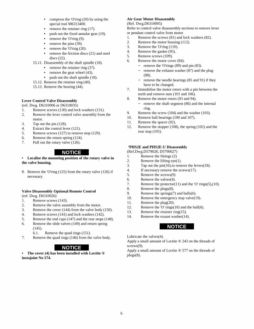
• compress the 'O'ring (20) by using the special tool M6313400.
• remove the retainer ring (17). • push out the fixed annular gear (19). • remove the 'O'ring (9). • remove the pins (39). • remove the 'O'ring (20). • remove the friction discs (21) and steel
discs (22). 15.11. Disassembly of the shaft spindle (18).
• remove the retainer ring (37). • remove the gear wheel (43). • push out the shaft spindle (18).
15.12. Remove the retainer ring (40). 15.13. Remove the bearing (44).
Lever Control Valve Disassembly (ref. Dwg. D6310006 or D6310035) 1. Remove screws (130) and lock washers (131). 2. Remove the lever control valve assembly from the
motor. 3. Tap out the pin (128). 4. Extract the control lever (121). 5. Remove screws (127) to remove stop (129). 6. Remove the return spring (124). 7. Pull out the rotary valve (126).
NOTICE • Localise the mounting position of the rotary valve in the valve housing. 8. Remove the 'O'ring (125) from the rotary valve (126) if
necessary. Valve Disassembly Optional Remote Control (ref. Dwg. D6310026) 1. Remove screws (143). 2. Remove the valve assembly from the motor. 3. Remove the cover (144) from the valve body (150). 4. Remove screws (141) and lock washers (142). 5. Remove the end caps (147) and the rear stops (148). 6. Remove the slide valves (149) and return spring
(145). 6.1. Remove the quad rings (151).
7. Remove the quad rings (146) from the valve body.
NOTICE • The cover (4) has been installed with Loctite ® instajoint No 574.
Air Gear Motor Disassembly (Ref. Dwg.D6310005) Refer to control valve disassembly sections to remove lever or pendant control valve from motor 1. Remove the screws (81) and lock washers (82). 2. Remove the motor housing (112). 3. Remove the 'O'ring (110). 4. Remove the gasket (95). 5. Remove screws (109). 6. Remove the motor cover (84).
− remove the 'O'rings (89) and pin (83). − remove the exhaust washer (87) and the plug
(88). − remove the needle bearings (85 and 91) if they
have to be changed. 7. Immobilise the motor rotors with a pin between the
teeth and remove nuts (101 and 106). 8. Remove the motor rotors (93 and 94).
− remove the shaft segment (86) and the internal ring.
9. Remove the screw (104) and the washer (103). 10. Remove ball bearings (100 and 107). 11. Remove the spacer (92). 12. Remove the stopper (108), the spring (102) and the
rear stop (105). ‘PHS2E and PHS2E-U Disassembly(Ref.Dwg.D579028, D5790027)1. Remove the fittings (2) 2. Remove the lifting eye(1). 3. Tap out the pin(16).to remove the levers(18). 4. If necessary remove the screws(17). 5. Remove the screws(9) 6. Remove the valves(4). 7. Remove the protector(11) and the 'O' rings(5),(10). 8. Remove the plugs(8). 9. Remove the springs(7) and balls(6). 10. Remove the emergency stop valve(19). 11. Remove the plug(20). 12. Remove the 'O' rings(10) and the ball(6). 13. Remove the retainer ring(15). 14. Remove the exaust washer(14).
NOTICE Lubricate the valves(4). Apply a small amount of Loctite ® 243 on the threads of screws(9). Apply a small amount of Loctite ® 577 on the threads of plugs(8).

7
Shut-off Valve Disassembly (Ref. Dwg.D6170004) 1. Remove the screw (202). 2. Remove the cover (201) with the spring (203). 3. Remove the ‘O’ ring (204) from the cover (201). 4. Remove the cover (213) and the ‘O’ ring (215). 5. Remove the diaphragm (211). 6. Immobilise the valve cone (214) by its hole with a rod
in one of two orifices of the body (209) and remove the screw (208).
7. Remove the valve cone (205,214) with joints (206) and distance ring (210) with the washer (207).
Emergency Stop Valve Disassembly (Ref. Dwg.D6170003) Refer to air control valve disassembly to begin disassembly 8. Remove emergency stop button (179). 9. Remove the setscrews (175). 10. Remove the spools (178). 11. Pull on the shuttle valve stop (180) with ball ( 176). 12. Remove the ‘O’ ring (181) from shuttle valve stop
(180) and spool (176). Cleaning, Inspection and Repair Use the following procedures to clean, inspect, and repair the components of the winch. • A bearing that appears loose or does not rotate smoothly must be replaced. Failure to observe this precaution will result in bearing and/or winch component damage. Clean all winch component parts in solvent (except for the brake friction disc). The use of a stiff bristle brush will facilitate the removal of accumulated dirt and sediments in the drum and reduction assembly. If drum bushings have been removed it may be necessary to carefully scrape old Loctite® from the drum bushing bore. Dry each part using low pressure, filtered compressed air. Clean the brake friction disc using a wire brush or emery cloth. Do not wash the brake friction disc in liquid. If the brake friction discs are oil soaked, they must be replaced. Inspection All disassembled parts should be inspected to determine their fitness for continued use. Pay particular attention to the following: 1. Inspect all gears for worn, cracked, or broken teeth. 2. Inspect all bushings for wear, scoring or galling. 3. Inspect all bearings for play, distorted races, pitting
and roller or ball wear or damage. Inspect bearings for freedom of freedom
4. Inspect shafts for ridges caused by wear. If ridges caused by wear are apparent on shafts, replace the shaft. Inspect all surfaces on which oil seal lips seat. These surfaces must be very smooth to prevent damage to the seal lip.
5. Inspect all threaded items and replace those having damaged threads.
6. Inspect all remaining parts for evidence of damage. Replace or repair any part which is in questionable condition. The cost of the part is often minor in comparison with the cost of redoing the job.
7. Smooth out all nicks, burrs, or galled spots on shafts, bores, pins or bushings.Examine all gear teeth carefully, and remove nicks or burrs.
8. Polish the edges of all shaft shoulders to remove small nicks which may have been caused during handling.
9. Remove all nicks and burrs caused by lockwashers. 10. Replace all gaskets, oil seals, and O’rings any time
the winch is disassembled for repair. 11. Inspect drum bushings (47) for wear, if thickness is
less than 0.039 in. (1 mm), replace drum bushings. 12. Inspect brake discs (21 and 22) for wear, if thickness
less than 0.354 in. (9 mm), replace them. Repair Actual repairs are limited to the removal of small burrs and other minor surface imperfections from gears and shafts. Use a fine stone or emery cloth for this work. Do not use steel wool. 1. Worn or damaged parts must be replaced. Refer to the
applicable Parts Listing for specific replacement parts information.
2. Inspect all remaining parts for evidence of damage. Replace or repair any part which is in questionable condition. The cost of the part is often minor in comparison with the cost of redoing the job.
3. Smooth out all nicks, burrs, or galled spots on shafts, bores, pins, or bushings.
4. Examine all gear teeth carefully, and remove nicks or burrs.
5. Polish the edges of all shaft shoulders to remove small nicks which may have been caused during handling.
6. Remove all nicks and burrs caused by lockwashers. 7. Replace all gaskets, oil seals, and 'O' rings removed
during winch disassembly. Assembly Instructions Winch Assembly (Ref. Dwg. D6310041) 1. Gear box assembly.
1.1. Assembly of the shaft spindle (18) − Install bearing (44) with the retainer ring
(40) − Put the shaft spindle (18) in the bearing
(4).Install the gear wheel (43) with the retainer ring (37)
1.2. Assembly of the fixed annular gear (19). − Install the friction disc (21) and steel disc
(22) in the gear box (45). − Install the 'O' ring (20) and the pin (39). − Install the 'O' ring (9) in the fixed annular
gear (19) , install this ass'y in the gear box (45) and secure with the retainer ring (17).

8
1.3. Install the needle bearings (14) and the spacer (16) in the planet (15).
1.4. Install the three planet ass'y , bearing studs (12) and stop rings (13) in the planet support (46).
1.5. Install the planet axle (11) and the bearing (10).
1.6. Install the planet support assembly. 1.7. After assembly of planet support (46) with the
fixed annular gear (19) and the shaft spindle (18) , check for good indexing of planet gears and repeat the above operation if necessary.
(Dwg.D6310013) • For correct assembly of planet gears, each planet gear must be positioned with the timing mark as shown on drawing D6310013.
1.8. Install the spring washer (49) and the output annular gear (50).
1.9. Assembly of the box cover − Install the oil seal (52) and the bearing (51
and 53). − Install the output shaft (5) with the
retainer ring (54) in the gear box cover. − Install the 'O' ring (9). − Install the gear box cover ass'y and secure
with screws (47) and washers (48). 2. Assembly of the brake piston
2.1. Install the brake piston with the 'O' rings (23 and 25).
2.2. Install bearing (36) , spring (41) and gasket (33).
3. Assembly of the front end cover. 3.1. Clean the mounting front end cover (30) bore
and apply a bead of Loctite No.460 on the backside of the oil seal (35).Install the oil seal.
3.2. Install the retainer ring (32). 3.3. Install the front end cover (30) and secure
with screws (34). 4. Install the three tie rod spacer (4) with the nuts (2)
and the washer (3). 5. Fill up the brake with oil. 6. Install the gasket (31) and the 'O' ring (27).
7. Install the motor ass'y and secure with the four screws.
8. Position the winch vertically with the motor end down.
9. Fill up the gear box with oil SAE 80W90 − kinematics viscosity 145 mm²/s at 40°C(104°F) − capacity of gear box : 0.13 gall (0.5 Litres)
10. Drum assembly 10.1. Scrape old Loctite from the drum bushing
bore and apply a bead of Loctite N°406 on the smooth face of drum bushings (38).
10.2. Install drum bushing in drum bushing bore by taking care to adjust the gaps of the drum bushing to 3.9 ins (100mm) do not allow any clearance between drum bushings and drum.
10.3. Lubricate drum bushings with grease. 10.4. Install the drum on the gear box assembly. 10.5. Lift out the drum to check for good
positioning of drum bushing 11. Clutch control assembly (PS SERIES)
11.1. Install plunger body (70) and plunger (61) on the rear end cover (55) and secure with screw (67) and washer (68).
11.2. Install bearing (71) on clutch axle (66) with retainer ring (65) and install the clutch (72) with the retainer ring (62).
11.3. Pull the plunger (61) to introduce the clutch axle with the spring (69) into the plunger body (70) and install the handle (65).
12. Assembly of the rear end cover (55). 12.1. Install bearing (58) on the rear cover. 12.2. Install exhaust washers (69) with ring (59).
13. Install spacer (64) on the output shaft (PS SERIES). Install the rear end cover Ass'y on the three tie rod (4) and secure with lock washers (3) and nuts (2).
Lever Control Valve Assembly (Ref. Dwg.D6310006 or D6310035) 1. Lubricate and install 'O' ring (125) on rotary valve
(126). 2. Lubricate and carefully install rotary valve in valve
housing (122). 3. Lubricate and install spring (124) on rotary valve.
Ensure pin (123) is installed in valve housing (122). 4. Install stop (129). Apply a small amount of Loctite®
243 to threads of screws (127) and install. 5. Install control handle (121) on rotary valve and align
pin hole. Install pin (128) to secure control handle. &

9
Air Gear Motor Assembly (Ref. Dwg. D6310005) 1. Install the stop (105) ,spring (102) and stopper (108). 2. Install the spacer (92). 3. Install the bearing (100 and 107) and secure with the
screw (104) and washer (103). 4. Install the internal ring of the bearing (85) on the rotor 5. motor (84) and secure with the retainer ring (86). 6. Install the motors rotors with a pin between the teeth
and secure with the nuts (101 and 106). 7. Install the pin (83) , the needle bearing (85 and 91) ,
the 'O' ring (89) , the exhaust washer (87) and the plug (88) in the motor cover.
8. install the motor ass'y on the motor cover with the screws (109)
9. Install the 'O' ring (110) and the gasket (95) in the motor housing (112).
10. Install the motor ass'y in the motor housing (112) and secure with the screws (81 and 82).
NOTICE
• To correctly assemble the exhaust washer, spacers, valve and spring, carefully follow instructions:
− Take the motor body and put it in the same position as mounting on the winch and view from the backside of the motor body, stopper, spring, valve and the spacer must be mounted in the left bore. Check for good functioning of the valve.
− The exhaust washer must be mounted on the same side as the valve in the right bore.
− Before assembly lubricate bearing with grade 2 grease.
− Install ball bearings so markings on bearing remain visible.
− After assembly of the air motor, it must turn smoothly in both direction.
− The screws (104 and 109) the nuts (101 and 106 must be secured with Loctite ® 243, secure the nuts with a centre punch.
PHS2E and PHS2E-U Assembly Assembly of the pendant control is the same as disassembly in opposite order. Pendant Control Adjustment. 1. Connect the inlet of the pendant to 100 psi (7 bar) air
supply. 2. Connect a manometer at the outlet of the lever to be
adjusted. 3. Tighten the adjustment setscrew to obtain a pressure
of 15 psi (1 bar) without action the lever. 4. Release the adjustment setscrew by a half turn
(pressure must fall to zero). 5. Push the lever. Check that pressure reaches 93 +/- 7
psi (6.5 +/- 0.5 bar). Check that there is no leak at the exhaust.
6. Release the lever, exhaust must occur and result in rapid pressure reduction.
7. Repeat operations “6 and 7” from 2 to 3 times. 8. Disconnect the manometer. Check to ensure that
there are no leaks when the lever is not activated. 9. Repeat the operations from 2 to 9 with each lever.

10
ACCESSORIES
Tooling installation M6313400 (Dwg.D6310031)
TEST
Testing Operational Tests Prior to initial use,all new,altered or repaired winches shall be tested to ensure proper operation. 1. Operate winch in both directions with no load.2. Check operation of free wheel and brake.3. Check operation of limit switches and other safety
devices when provided.4. Check all winch mounting bolts are secure.
Load test Prior to initial use, all new, extensively repaired, or altered winches shall be load tested by or under the direction of a person trained in the operation and service of this winch and a written report furnished confirming the rating of the winch.
− For air winches LS series. The minimum load test for European countries are
according to the chart below.If not found below you should use the tests recommended by the FEM.
The dynamic test shall be carried out with an overload coefficient ρ1 = 1,2 i.e. with a load equal to 120% of the safe working load. All motions shall be carefully operated in turn, without checking speeds of temperature rises in the motors.
the static test shall be carried out with an overload coefficient ρ2 = 1,4 i.e. with a load equal to 140% of the safe working load.The test must be carried out under still conditions and consists in hoisting the safe working load to a small distance above the ground and then adding the required surplus without shock.
− For air winches PS series. The dynamic test shall be carried out with the nominal
line pull.
The static test shall be carried out with an overload coefficient ρ2 = 1,4 i.e. with a load equal to 140% of the safe working load.

11
NOTES
12
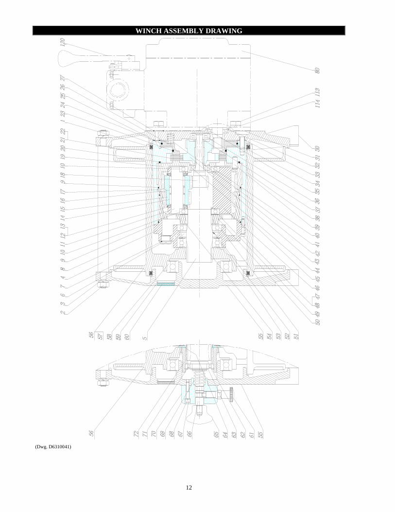
WINCH ASSEMBLY DRAWING
(Dwg. D6310041)

13
WINCH ASSEMBLY PART LIST
ITEM NO.
DESCRIPTION OF PART
TOTAL QTY
PART NO.
1 Quad-Ring 2 58231029
2 Nut 6 43000211 3 Lock washer 6 45200010 Lock washer -*- 6 45100210
4 Tie rod spacer (short drum) Tie rod spacer (long drum)
3 96310008 96310052
5 Output shaft 1 96310026
Output shaft TD-20° 1 96310391
•••• 6 Plug 2 65119732
7 Copper joint 2 58403431 8 Gear box cover 1 96310005
•••• 9 ‘O’ ring 2 58231129
10 Bearing 2 50800008
11 Planet axle 3 96200060
12 Bearing stub 6 56053520
13 Stop ring 6 57319832 14 Needle bearing 6 56502620
15 Planet Gear 3 96200075
16 Spacer 3 96190024 •••• 17 Retainer ring 1 47847832
18 Shaft spindle 1 96310094
19 Fixed annular gear 1 96310096
•••• 20 ‘O’ ring 1 58221829
21 Friction disc 4 63059932
22 Steel disc 3 63060032
•••• 23 ‘O’ ring 1 58230929
•••• 24 ‘O’ ring 1 58212829
•••• 25 ‘O’ ring 1 58212529
26 Brake piston 1 96310093
•••• 27 ‘O’ ring 1 58226629
30 Front end cover 1 96310091 Front end cover TD-20° 1 96310392
•••• 31 Gasket 1 96310118
32 Retainer Ring 1 47703035
•••• 33 Gasket 1 96310097
34 Screw 6 41102203
ITEM NO.
DESCRIPTION OF PART
TOTAL QTY
PART NO.
•••• 35 Oil seal 1 58020030
36 Bearing 1 50100001
•••• 37 Retainer ring 1 47700015
38 Bushing 3 96310014 39 Pin 5 46000416
•••• 40 Retainer ring 1 47703032
41 Spring 11 69165532
•••• 42 ‘O’ ring 1 58207129
43 Gear wheel 1 96310095 44 Bearing 1 50000002
45 Gear box 1 96310092
Gear box TD-20° 1 96310393 46 Satellite support 1 96200010
47 Screw 6 41311106
48 Lock washer 6 45200004 49 Spring washer 1 69172132
50 Output annular gear 1 96200031
51 Bearing 1 50800009
•••• 52 Oil seal 1 58012130
53 Bearing 1 50050009
54 Retainer Ring 1 47700045 55 Rear End Cover 1 96310003
56 Short Drum (180mm) 1 96310001
Short Drum (180mm) TD-20° 1 96310399 Long Drum (360mm) 1 96310050
Long Drum (360mm) TD-20° 1 96310390
57 Wire rope wedge 1 96310023
58 Bearing 1 50050014
•••• 59 Ring 9 47800639
•••• 60 Exhaust washer 9 67600303
80 Air gear motor 1 -
113 screw 4 41000201 114 lock Washer 4 45200006
Lock washer -*- 4 45100206
120 Air control valve 1 -
Wedge 1 96310023
Winches with clutch control Substitute or add the following parts on winch with clutch control
55 Rear End Cover 1 96310027
Rear End Cover TD-20° 1 96310389 56 Short Drum (180mm) 1 96310028
Short Drum (180mm) TD-20° 1 96310400
Long Drum (360mm) 1 96310051
Long Drum (360mm) TD-20° 1 96310397 61 Plunger 1 66288132
62 Retainer Ring 1 47703047
63 Retainer Ring 1 47700025 64 Spacer 1 96310007
65 Handle 1 69566232
66 Clutch Axle (Short drum) 1 96310037 Clutch Axle (long drum) 96310053
67 Screw 3 41307906
68 Washer 3 45200005
69 Spring 1 69188932 70 Body 1 96180060
71 Bearing 1 50800005
72 Clutch 1 96310029
•••• Recommended spare
-*- For LS1000RGC-PH7M-CE/8596

14
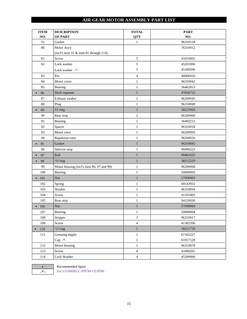
AIR GEAR MOTOR ASSEMBLY DRAWING
(Dwg. D6310005)
15
AIR GEAR MOTOR ASSEMBLY PART LIST
ITEM NO.
DESCRIPTION OF PART
TOTAL QTY
PART NO.
31 Gasket 1 96310118
80 Motor Ass'y
(incl's item 31 & item 81 through 114)
76310012
81 Screw 5 41019001
82 Lock washer 5 45201006
Lock washer -*- 5 45100206
83 Pin 4 46000416
84 Motor cover 1 96310042
85 Bearing 1 56462813
•••• 86 Shaft segment 1 47836732
87 Exhaust washer 1 96200045
88 Plug 1 96310049
•••• 89 'O' ring 2 58225929
90 Rear stop 2 96200069
91 Bearing 1 56492213
92 Spacer 1 96310018
93 Motor rotor 1 96200093
94 Repulsion rotor 1 96200026
•••• 95 Gasket 1 96310045
96 Selector stop 1 96090223
•••• 97 Ball 1 69401625
•••• 98 ‘O’ring 1 58212229
99 Motor housing (incl's item 96, 97 and 98) 1 96200008
100 Bearing 1 50600003
•••• 101 Nut 1 57000003
102 Spring 1 69143932
103 Washer 1 96310054
104 Screw 1 41103403
105 Rear stop 1 94120030
•••• 106 Nut 1 57000004
107 Bearing 1 50600004
108 Stopper 1 96310017
109 Screw 4 41302206
•••• 110 ‘O’ring 1 58221729
111 Greasing nipple
Cap -*-
1
1
67102227
61017128
112 Motor housing 1 96310078
113 Screw 4 41000201
114 Lock Washer 4 45200006
•••• Recommended Spare
-*- For LS1000RGC-PH7M-CE/8596
16
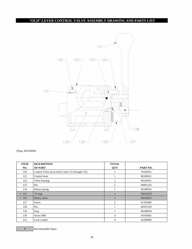
“OLD” LEVER CONTROL VALVE ASSEMBLY DRAWING AND PAR TS LIST
(Dwg. D6310006)
ITEM NO.
DESCRIPTION OF PART
TOTAL QTY
PART NO.
120 Control Valve Ass'y (incl's item 121 through 131) 1 76310011
121 Control lever 1 96180031
122 Valve housing 1 96310021
123 Pin 2 46001216
124 Return spring 1 96180035
• 125 ‘O’ring 1 58210229
• 126 Rotary valve 1 96310022
127 Screw 2 41103403
128 Pin 1 46507220
129 Stop 1 96180034
130 Screw HM 4 41016601
131 Lock washer 4 45200006
•••• Recommended Spare

17
CONTROL VALVE ASSEMBLY DRAWING AND PARTS LIST
(Dwg. D6310035)
ITEM NO.
DESCRIPTION OF PART
TOTAL QTY
PART NO.
119 Control Valve Ass'y (incl's item 121 through 134) 1 -
121 Control lever 1 96310056
122 Valve housing 1 96310058
123 Pin 2 46001216
124 Return spring 1 96180035
• 125 ‘O’ring 1 58210229
• 126 Rotary valve 1 96310022
127 Screw 2 41103403
128 Pin 2 46507220
129 Stop 1 96180034
130 Screw HM 4 41016601
131 Lock washer 4 45200006
132 Handle 1 69566232
133 Setscrew 1 42001507
134 Axle 1 96310057
•••• Recommended Spare

18
“NEW” LEVER CONTROL VALVE ASSEMBLY DRAWING
From 1st December 2009
21
16
14
12
6
15
5
11
9
4
810
13
19
20
17
18
2
3
1
5
7
(Dwg.D6310863)
19
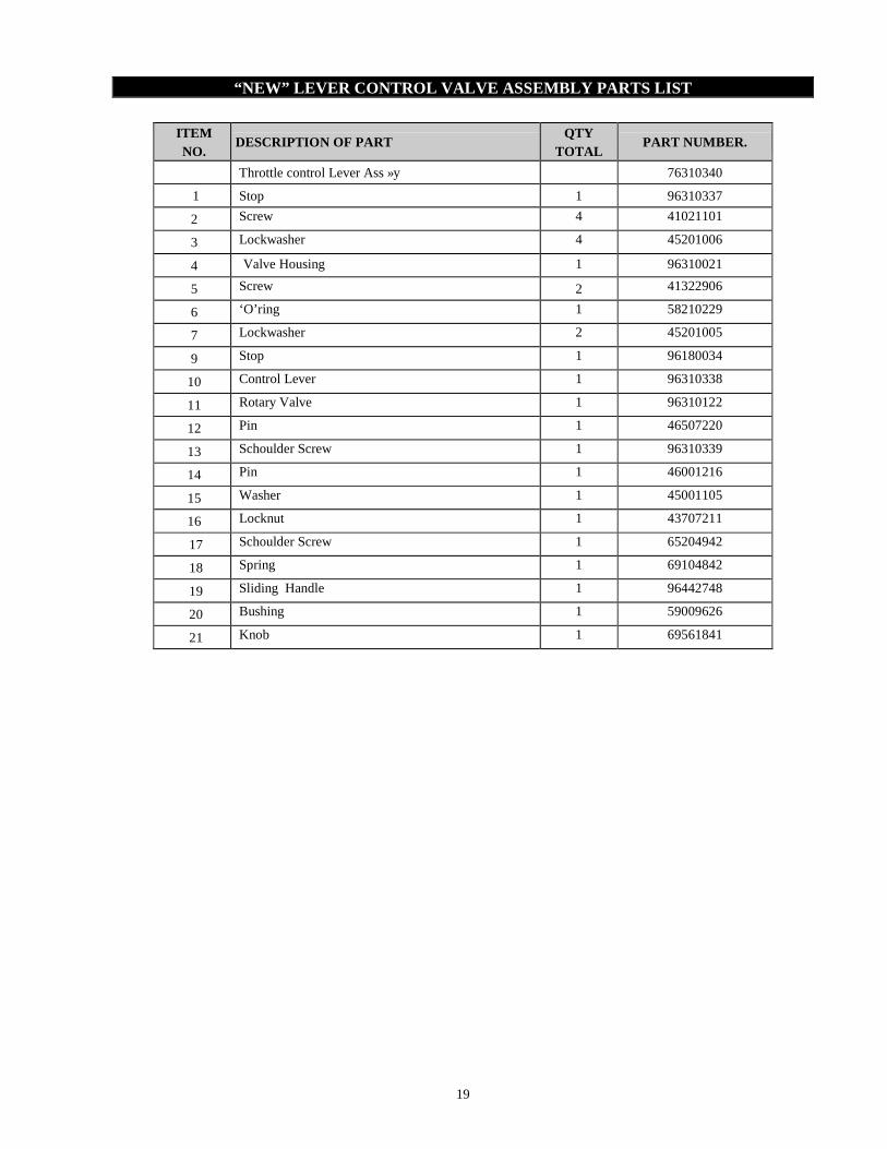
“NEW” LEVER CONTROL VALVE ASSEMBLY PARTS LIST
ITEM NO.
DESCRIPTION OF PART QTY
TOTAL PART NUMBER.
Throttle control Lever Ass »y 76310340
1 Stop 1 96310337
2 Screw 4 41021101
3 Lockwasher 4 45201006
4 Valve Housing 1 96310021
5 Screw 2 41322906
6 ‘O’ring 1 58210229
7 Lockwasher 2 45201005
9 Stop 1 96180034
10 Control Lever 1 96310338
11 Rotary Valve 1 96310122
12 Pin 1 46507220
13 Schoulder Screw 1 96310339
14 Pin 1 46001216
15 Washer 1 45001105
16 Locknut 1 43707211
17 Schoulder Screw 1 65204942
18 Spring 1 69104842
19 Sliding Handle 1 96442748
20 Bushing 1 59009626
21 Knob 1 69561841

20
NOTES
21
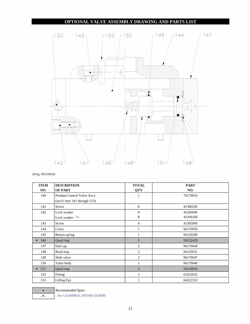
OPTIONAL VALVE ASSEMBLY DRAWING AND PARTS LIST
(Dwg. D6310026)
ITEM NO.
DESCRIPTION OF PART
TOTAL QTY
PART NO.
140 Pendant Control Valve Ass'y
(incl's item 141 through 153)
1 76170010
141 Screw 8 41300206
142 Lock washer 8 45200006
Lock washer -*- 8 45100206
143 Screw 4 41305906
144 Cover 1 96170050
145 Return spring 1 94120289
•••• 146 Quad ring 2 58232429
147 End cap 2 96170049
148 Read stop 2 94120031
149 Slide valve 2 96170047
150 Valve body 1 96170046
•••• 151 Quad ring 2 58229029
152 Fitting 3 61652632
153 Lifting Eye 1 64222332
•••• Recommended Spare
-*- For LS1000RGC-PH7M-CE/8596

22
TWO LEVER PENDANT ASSEMBLY DRAWING
(Dwg.D5790002)
23
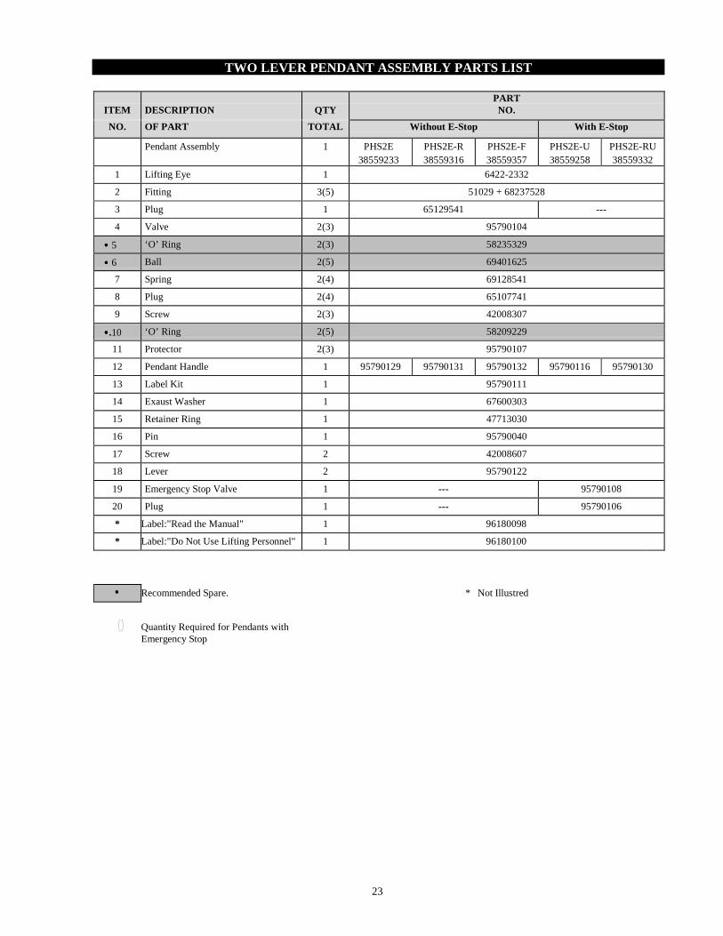
TWO LEVER PENDANT ASSEMBLY PARTS LIST
ITEM DESCRIPTION QTY PART NO.
NO. OF PART TOTAL Without E-Stop With E-Stop
Pendant Assembly 1 PHS2E 38559233
PHS2E-R 38559316
PHS2E-F 38559357
PHS2E-U 38559258
PHS2E-RU 38559332
1 Lifting Eye 1 6422-2332
2 Fitting 3(5) 51029 + 68237528
3 Plug 1 65129541 ---
4 Valve 2(3) 95790104
•••• 5 ‘O’ Ring 2(3) 58235329
•••• 6 Ball 2(5) 69401625
7 Spring 2(4) 69128541
8 Plug 2(4) 65107741
9 Screw 2(3) 42008307
••••.10 ‘O’ Ring 2(5) 58209229
11 Protector 2(3) 95790107
12 Pendant Handle 1 95790129 95790131 95790132 95790116 95790130
13 Label Kit 1 95790111
14 Exaust Washer 1 67600303
15 Retainer Ring 1 47713030
16 Pin 1 95790040
17 Screw 2 42008607
18 Lever 2 95790122
19 Emergency Stop Valve 1 --- 95790108
20 Plug 1 --- 95790106
* Label:"Read the Manual" 1 96180098
* Label:"Do Not Use Lifting Personnel" 1 96180100
•••• Recommended Spare. * Not Illustred
Quantity Required for Pendants with Emergency Stop

24
SHUT-OFF VALVE ASSEMBLY DRAWING AND PARTS LIST
(Dwg.D6170004)
ITEM NO
DESIGNATION OF PART
QTY TOTAL
PART NUMBER
200 Shut-off Valve Assembly (incl’s item 201 through 215) 1 76170016
201 Cover 1 96170059
202 Screw 7 41306706
203 Spring 1 69158732
•••• 204 ‘O’ Ring 1 58214829
205 Valve Cone 1 96170053
•••• 206 Joint 2 96170056
207 Washer 2 45700005
208 Screw 1 41308206
209 Body 1 96170061
210 Distance Ring 1 96170055
•••• 211 Diaphragm 1 67716341
212 Fitting 2 61652632
213 Cover 1 96170052
214 Valve Cone 1 96170054
•••• 215 ‘O’ Ring 1 58209229
•••• Recommended Spare.

25
“OLD” EMERGENCY STOP VALVE ASSEMBLY DRAWING AND PAR TS LIST
(Dwg.D6170003)
ITEM NO
DESIGNATION OF PART
QTY TOTAL
PART NUMBER
175 Setscrew 3 42008207
176 Ball 1 69401625
177 Spring 3 69113941
178 Spool 3 95790085
179 Emergency Stop Bottom 1 68598632
180 Shuttle Valve Stop 1 95790098
•••• 181 ‘O’ Ring 9 58209229
182 Label Kit 1 95790099
201 Cover 1 96170059
202 Screw 7 41306706
203 Spring 1 69158732
•••• 204 ‘O’ Ring 1 58214829
205 Valve Cone 1 96170053
•••• 206 Joint 2 96170056
207 Washer 2 45700005
208 Screw 1 41308206
210 Distance Ring 1 96170055
211 Diaphragm 1 67716341
213 Cover 1 96170052
214 Valve Cone 1 96170054
216 Plug 1 65107741
217 Setscrew 1 42007407
218 Nozzle 1 96170071
219 Nipple 1 61330732
220 Body 1 96170068
221 Emergency stop Valve Assembly (incl’s item 175 through 220) 1 76170018
•••• Recommended Spare.
26
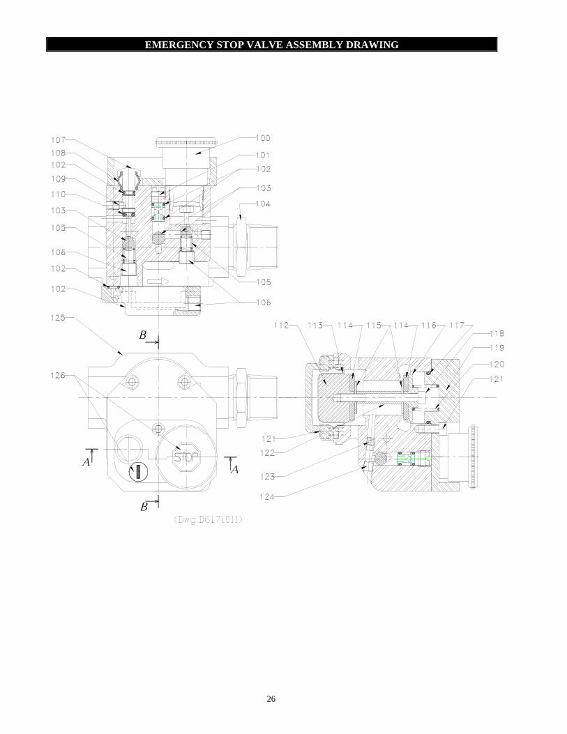
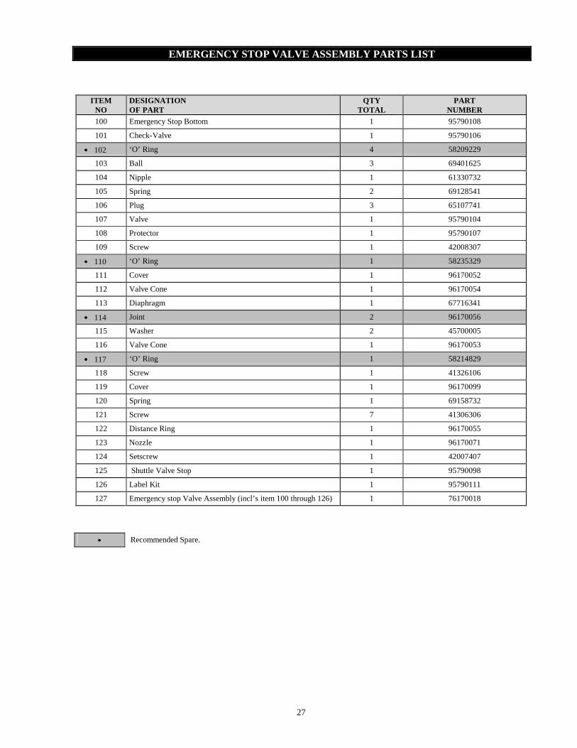
EMERGENCY STOP VALVE ASSEMBLY DRAWING
A
B
A
B
27
EMERGENCY STOP VALVE ASSEMBLY PARTS LIST
ITEM NO
DESIGNATION OF PART
QTY TOTAL
PART NUMBER
100 Emergency Stop Bottom 1 95790108
101 Check-Valve 1 95790106
•••• 102 ‘O’ Ring 4 58209229
103 Ball 3 69401625
104 Nipple 1 61330732
105 Spring 2 69128541
106 Plug 3 65107741
107 Valve 1 95790104
108 Protector 1 95790107
109 Screw 1 42008307
•••• 110 ‘O’ Ring 1 58235329
111 Cover 1 96170052
112 Valve Cone 1 96170054
113 Diaphragm 1 67716341
•••• 114 Joint 2 96170056
115 Washer 2 45700005
116 Valve Cone 1 96170053
•••• 117 ‘O’ Ring 1 58214829
118 Screw 1 41326106
119 Cover 1 96170099
120 Spring 1 69158732
121 Screw 7 41306306
122 Distance Ring 1 96170055
123 Nozzle 1 96170071
124 Setscrew 1 42007407
125 Shuttle Valve Stop 1 95790098
126 Label Kit 1 95790111
127 Emergency stop Valve Assembly (incl’s item 100 through 126) 1 76170018
•••• Recommended Spare.

28
TORQUE LIMITOR ASSEMBLY DRAWING AND PARTS LIST
(Dwg.D6360005)
ITEM NO
DESIGNATION OF PART
QTY TOTAL
PART NUMBER
230 Torque limitor Ass'y 1 76360001
231 Screw 1 42007407
232 Screw 1 42001607
233 Nut 1 43007811
234 Ball 1 69400125
235 Spring Seat 1 96360023
•••• 236 Spring 1 69159432
237 Nut 1 43001111
238 Washer 1 96360019
•••• 239 Diaphragm 1 96360020
240 Cover 1 96360015
•••• 241 Usit-Ring 2 58409731
242 Screw 2 96360022
243 Body 1 96360016
244 Screw 4 41314906
•••• 245 'O'Ring 2 58210729
246 Valve 1 96360017
247 Plug 1 65172032
248 Nozzle 1 96170071
•••• 249 'O'Ring 1 58222329
250 Joint 1 96360021
251 Screw 1 96360018
•••• 252 'O'Ring 2 58209229
•••• Recommended Spare.

29
LIMIT SWITCHES ASSEMBLY DRAWING
17
3
12x
15 x
25
14 16
23 x
1040
11
6
20
21
7
30
13
22
20
11
11
26
39x
9x24
5
8
18
19
(Dwg.D6510862) NOTE: X: Screws securized with Loctite® 243 or equivalent on the threads

30
LIMIT SWITCHES ASSEMBLY DRAWING
35
34
36
34
28
29
27x
Cam to adjustTop limit Switch
Cam to adjustBottom Limit Switch
39x
30
38
37
33
31 323231
32
41
37
37
43
44
42
(Dwg.D6510862)

31
LIMIT SWITCHES PART LIST
ITEM NO.
DESCRIPTION OF PART QTY
TOTAL PART NUMBER.
3 Pin 1 46508320
5 Sun Gear (Short drum) 1
96510015
Sun Gear (Long drum) 96510014
6 Retainer ring 1 47801039
7 Bearing 1 50005000
8 Washer 1 45001105
9 Screw 1 41005101
10 Valve Support 1 96510007
11 Double Geared Pinion 3 96510017
12 Screw 2 41322706
13 Cams Support 1 96510008
14 Housing 1 96510001
15 Screw 2 41019101
16 Cover 1 96510002
17 Retainer Ring 1 47837241 18 Nut 3 43803742
Nut -*- 3 43707211 Lock washer -*- 3 45100205
19 Screw 3 42007707 20 Retainer Ring 2 47803342 21 Spring Washer 2 69103442 22 Washer 1 45001110 23 Axle 1 96510003 24 Gasket 1 96510012 25 Cable Glands 1 60903542 26 ‘O’ring 1 58239129 27 Screw 2 41316506 28 Pneumatic Valve 2 68558741 29 Cam 2 96510004 30 Screw 2 41024401 31 Elbow 2 68280132 32 Fitting 3 68246128
33 Pipe (Short drum)
1 96510025
Pipe (Long drum) 96510028 34 Elbow Fitting with nozzle 2 96510030
35 Air pilot Valve 1 68598841 Valve Base 1 68598941
36 Elbow 1 68159828 37 Hose (m) 1025U 04 01
38 Protective hose (Short Drum)
1 96510023
Protective hose (Long Drum) 96510024 39 Screw 6 41316706 40 Flange 1 96510011 41 Tee 1 61394532 42 Nipple 1 61385232 43 Screw 2 41023401
Screw -*- 2 41325006 Lock washer -*- 2 45100208
44 Locknut 2 43706511 Nut -*- 2 43003511
Lock washer -*- 2 45100208
-*- For LS1000RGC-PH7M-CE/8596

32
DRUM GUARD ASSEMBLY DRAWING AND PART LIST
2
1
ITEM DESIGNATION QTY PART NUMBER NO OF PART TOTAL SHORT DRUM LONG DRUM
Drum Guard Ass'y (Incl's item 1 and 2) 1 76310026 76310027
1 Drum Guard 1 96310038 96310065
2 Screw 1 41321806 41325006

35
WARRANTY
HOIST AND WINCH LIMITED WARRANTY
See our general conditions of sales mentioned on our proposal, acknowledgement receipt, invoice.
INGERSOLL-RAND guarantees the equipment sold and supplied by itself against any defect or flaw in manufacture or operation under the conditions and within the limits hereafter. - the guarantee is only valid if the customer has satisfied the general obligations of the present contract and, in particular, of settlement. - the guarantee is strictly limited to INGERSOLL-RAND equipment. It does extend to supplies and accessories which are not of its manufacture. - the guarantee does not extend to assemblies or machines in which INGERSOLL-RAND equipement is incorporated and in particular to the performances of these assemblies or machines. - when INGERSOLL-RAND equipment is incorporated into one or other assembly or machine by the customer, he alone is responsible for the adaptation, the choice and the suitability of the INGERSOLL-RAND equipment, INGERSOLL-RAND 's diagrams, surveys and layouts being given only for guidance, unless there is a special stipulation in the acceptance of order, defined in the acknowledgement of receipt. - INGERSOLL-RAND does not guarantee components and accessories it does not sell. Defects in fitting, adaptation, design, connection and running of the assembly or part of the assembly put together by the customer are not covered by the guarantee. INGERSOLL-RAND equipment and material as well as the assemblies or machines set up by the customer or by a third party are assumed to be operated and used under the sole control of the customer or third party. - The duration of the guarantee is for 6 months from the start up of the equipment by the customer. The start up must be made at the latest three months after dispatch of the equipment or its being made available. - INGERSOLL-RAND has the right to demand from its customer proof of the date of start up. - The guarantee period is reduced to half if the equipment is used day and night. - The length of guarantee is neither prolonged nor interrupted by either amicable or litigious claims by the customer. - At the expire of this period, the guarantee ceases incontestably. - The obligations of the INGERSOLL-RAND guarantee will only come into effect if the customer proves that the defect or flaw appeared during normal operating conditions for this type of material, or in the course of normal use as specified by INGERSOLL-RAND
- It does not apply in the event of user's mistake, negligence, imprudence, faulty superintencence or maintenance, inattention to the instructions or directions for use of low quality lubricants. INGERSOLL-RAND ’s liability is disclaimed for all damage brought about by loss or leaks of oil. - No guarantee applies either for fortuitous incidents or force major, or for wear, replacements or repairs caused by normal use of the equipment. - The guarantee is restricted to reconditioning in INGERSOLL-RAND 's premises at its expense and as soon as possible the equipment and parts recognised as faulty by its technical or after sales services, which are sent carriage paid and packing free, without there being any claim for damage arising, such as injury to personnel, damage to property other than that covered by the present contract, loss of possession, of production, commercial detriment or loss of profit. - During the guarantee period, the cost of labour for dismantling and reassembling equipment outside INGERSOLL-RAND 's premises, the cost of moving faulty, replaced or repaired equipment and the travelling and living expenses of INGERSOLL-RAND 's engineers are covered exclusively by the customer. - In order to obtain the advantages of the guarantee, the customer must advice INGERSOLL-RAND without delay and in writing of the defects and flaws in his equipment of which he is complained and furnish proof of their genuine nature. He must give INGERSOLL-RAND or its agents or technicians every facility to verify the defects or flaws and to put them right. - The guarantee does not apply if the equipment is returned to INGERSOLL-RAND in a condition other than in which it broke down or if the seal has been removed, or if it has been dismantled, repaired or modified by a third party, or by the user or the customer. - After having been duly informed of the defect or flaw in its equipment, INGERSOLL-RAND will put it right as quickly as possible, reserving the right, in certain cases, to modify the whole or part of the equipment so as to meet its obligations. - The customer agrees that INGERSOLL-RAND will not be responsible for damage in the event that the customer has not fulfilled one or other of the obligations set out above. - Parts replaced free of charge remain the property or INGERSOLL-RAND . - The guarantee does not apply to wearing parts.
IMPORTANT NOTICE
It is our policy to promote safe delivery of all orders. This shipment has been thoroughly checked, packed and inspected before leaving our plant and receipt for it in good condition has been received from the carrier.Any loss or damage which occurs to this shipment while enrolee is not due to any action or conduct of the manufacturer.
VISIBLE LOSS OR DAMAGE If any of the goods called for on the bill of lading or express receipt are damaged or the quantity is short, do not accept them until the freight or express agent makes an appropriate notation on your freight bill or express receipt.
CONCEALED LOSS OR DAMAGE When a shipment has been delivered to you in apparent good
condition, but upon opening the crate or container, loss or damage has taken place while in transit, notify the carrier's agent immediately.
DAMAGE CLAIMS You must file claims for damage with the carrier; It is the transportation compagny's responsability to reimburse you for repair or replacement of good damaged in shipment. Claims for loss or damage in shipment must not be deducted from the Ingersoll-Rand invoice, nor should payment of Ingersoll-Rand invoice be withheld awaiting adjustment of such claims as the carrier guarantees safe delivery, You may return products damaged in shipment to us for repair, which services will be for your account and form your basis for claim against the carrier.