particle separation under the co-action of...
TRANSCRIPT
PARTICLE SEPARATION UNDER THE CO-ACTION OF BROWNIAN MOTION AND OPTICAL FORCE IN NEAR-FIELD SPECKLE PATTERNS
H. T. Zhao1, G. Zhang1, L. K. Chin1, H. Cai2, J. F. Song2, Z. C. Yang3, E. P. H. Yap4, W. Ser1,
D. L. Kwong2 and A. Q. Liu1† 1School of Electrical and Electronic Engineering, Nanyang Technological University, Singapore 639798
2Institute of Microelectronics, A*STAR (Agency for Science, Technology and Research), Singapore 117685
3Institute of Microelectronics, Peking University, Beijing 100871, China 4Lee Kong Chian School of Medicine, Nanyang Technological University, Singapore 639798
ABSTRACT
Continuous separation of nano-sized molecules has great importance in biomedical applications. This paper represents a near-field optical approach to separate nanoparticles using speckle patterns. Near-field random light patterns (speckle pattern) are generated by the repeated coupling and interference of light in nano-waveguide arrays. The movements of 2-μm and 0.5-μm particles are studied under the co-action of Brownian motion and the exerted optical force. The experimental results show that the 2-μm particle has an average lateral displacement of 10 μm, which is considerably larger than that of the 0.5-μm particle. This method avoids the stringent optical systems and broadens the perspectives of optical manipulation in real-life applications.
KEYWORDS
Particle separation, near-field speckle pattern, waveguide array, optical force, Brownian motion INTRODUCTION
Manipulation and sorting of biomolecules raise great interest in biomedical and chemical applications, such as oncology [1], stem cell research [2], optogenetics [3,4]. Separating targeted bio-samples from the surrounding environment will tremendously benefit diagnostic and therapeutic operations and plays a vital role in diagnosis of diseases such as cancer, HIV and H1N1 [5]. Optical manipulation is a new generation of techniques that use the momentum transfer during light-matter interactions to achieve a physical motion [6-8]. It is ideally suitable to manipulate biomolecules due to its non-contact manner and high selectivity to sample properties.
Current optical methods basically manipulate the target samples by using an elaborately designed light field in either far-field [9,10] or near-field region [11,12]. In those approaches, the performance of an optical manipulation is greatly influenced by the stability and quality of the light field. However, the light field may suffer from considerable scattering in the complex media of real-life applications such as biological tissues. Meanwhile, the current approaches generally require stringent optical setups which impose a substantial barrier for industrial integration and non-optical researchers. Therefore, the approach based on random light fields, which are known as speckle patterns, is promising to
achieve simple and low-cost particle manipulation. The reported far-field speckle pattern is diffraction limited and hence has difficulty in dealing with nano-sized particles [13, 14]. In this paper, a near-field approach is proposed to separate particles using the speckle pattern in waveguide arrays.
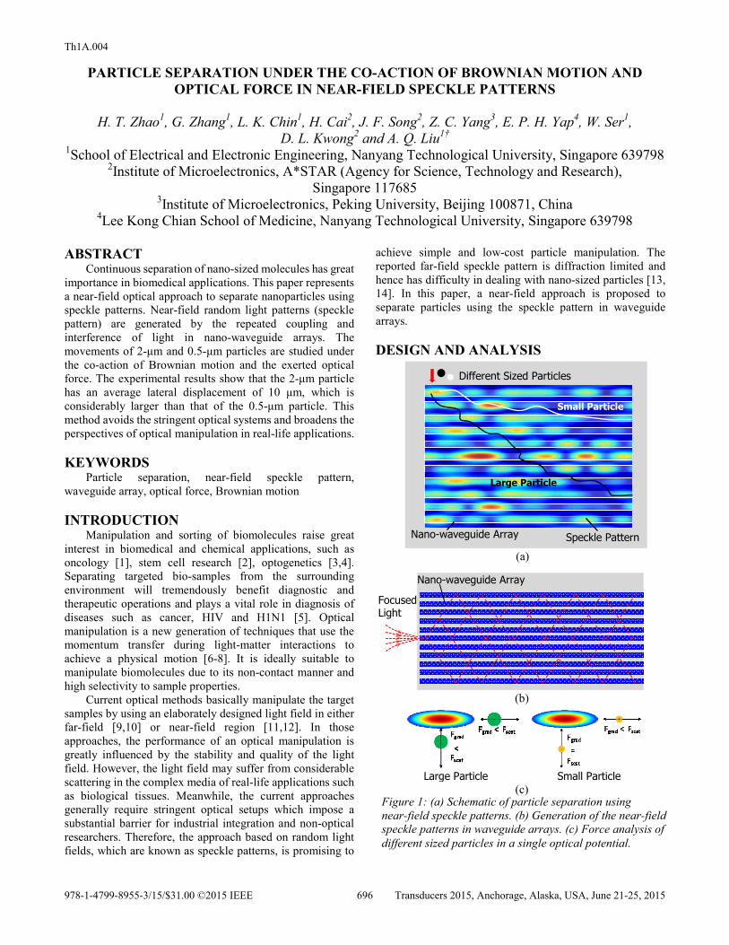
DESIGN AND ANALYSIS
Nano-waveguide Array
Different Sized Particles
Speckle Pattern
Small Particle
Large Particle
(a)
Focused Light
Nano-waveguide Array
(b)
Large Particle Small Particle(c)
Figure 1: (a) Schematic of particle separation using near-field speckle patterns. (b) Generation of the near-field speckle patterns in waveguide arrays. (c) Force analysis of different sized particles in a single optical potential.
978-1-4799-8955-3/15/$31.00 ©2015 IEEE 696 Transducers 2015, Anchorage, Alaska, USA, June 21-25, 2015
Th1A.004

Figure 1 shows the working princmanipulation using near-field speckle pattgenerate the near-field speckle pattern, a focwith a wavelength of 1550 nm is couplewaveguide as shown in Figure 1(b). Thcoupling back and forth from one wavegwaveguides, forming a large number of oprandom phases. Then the waves interfere wieventually form a complex and random ligthe speckle pattern is reconfigurable by chaposition, laser wavelength or the surroundibackground image in Figure 1(a) is a typicaThe red spots stand for high-energy potentithe blue areas stand for low-energy regiopotential will exert an optical gradient forceforce to nearby particles. The exerted opRayleigh particle is shown in Figure 2. It cthe scattering force is larger than gradienparticles, whereas is smaller than gradientparticles.
When different sized particles diffusefield, they will move differently under tBrownian motion and the exerted optical fomovements can be modeled with the follequation [15],
2 (Bmr r k T W Fγγ+ = +
where r , m and 6 Rγ πη= are the particle’and friction coefficient, η is the viscosity omedium, W is a white noise vector, kB isconstant, T is the system temperature and Fforce as a function of particle position.
If we neglect the inertial effects in theand solely consider the movement in the tranEq. (1) can be simplified to
(r)2 SEFr D W
γ= +
0
2
4
6
0 0.5 1
Forc
e (x
10-8
N/W
)
Particle Radius (µm)
Gradient Force
Scattering Force
Figure 2: Typical values of optical scatterforce for Rayleigh particles.
ciple of particle erns. In order to cused laser beam ed into a single
he light wave is guide to adjacent ptical waves with ith each other and ght pattern. Here anging the source ing medium. The al speckle pattern. ial centers, while
ons. Each optical e and a scattering ptical force on a learly shows that
nt force for large t force for small
e into the optical the co-action of orce. The particle lowing Langevin
(r) (1)
’s velocity, mass f the surrounding s the Boltzmann F(r) is the optical
e particle motion nsverse direction,
(2)
where BSE
k TDγ
= is the Stok
coefficient of the Brownian particleWhen the particle is in a sin
shown in Fig. 1(c), the gradient forsmall particles is smaller than thelongitudinal direction. That is becfocused in this direction. Thereformove rightwards. However, in the light spot has a length of only 200and the gradient force is comparablefor small particles. Therefore, theparticles in Eq.(2) is smaller than threlationship theoretically indicates have a larger transverse Brownian particles. In this way, different-separated when flowing through the
Three-dimensional simulations8.01 to investigate the light pattersimulated speckle patterns 40 nmsurface. The random pattern is recthe light source position and waveleforce analysis of the zoom-in regio
1.5 2
ring and gradient
Figure 3: Simulated near-field spnm above the waveguide surface
(a)
(b) Figure 4: Force analysis of (a) 2particles, respectively. (White ar
kes-Einstein’s diffusion
. ngle optical potential as rce for both the large and e scattering force in the ause the light is loosely re, all the particles will transverse direction, the nm, i.e. tightly focused, e with the scattering force e second term of small
hat of large particles. This that large particles will displacement than small
-sized particles can be e speckle pattern.
s are conducted in RSoft rns. Figure 3 shows the
m above the waveguide onfigurable by changing
ength. Figure 4 shows the n of Figure 3. The white
peckle patterns 40 e.
2-μm and (b) 0.5-μm rrow: resultant force)
697

arrow represents the magnitude and direction of the resultant force, which clearly shows that the 2-μm particle experiences constantly downward force, whereas the 0.5-μm particle experiences either upward or downward force depending on its location. FABRICATION AND EXPERIMENTS
The silicon nano-photonic device is fabricated on a silicon-on-insulator wafer with a device layer of 220 nm and a buried-oxide layer of 2 μm. Figure 5(a) and (b) show the SEM images of waveguide array with 11 and 5 waveguides, respectively. The fabrication steps include: (1) silicon etching using SiO2 as hard mask, (2) 2-μm cladding HDP SiO2 deposition and (3) etching to release the window region [16]. The microchannel is fabricated with polydimethylsiloxane (PDMS) using soft-lithography technology. Then the silicon and PDMS chips are bonded together after careful surface treatment. The dimension of the final hybrid chip is 16 mm (length) × 3 mm (width) × 2 mm (height).
Figure 6 shows the experimental setup to generate and control the required light patterns. Light source from a tunable laser source (Santec TCL510) first passes through the EDFA (Amonics EDFA-CL-27) to amplify the light power to around 100 mW. 2% of light is detected by the photo detector (PD) to monitor the power level while most of the energy is coupled into the input waveguide using an optical tapered lensed fiber. A fiber polarization controller adjusts the light polarization to the transverse-magnetic polarization mode of the waveguide. The light after the hybrid chip is detected by an optical spectrum analyzer (OSA, Yokogawa AQ6370C) for wavelength and power monitoring.
The polystyrene beads (Polysciences) with diameters of
0.5 μm or 2 μm are flowed into the microchannel using syringe pump (Harvard PhD 2000). The particle motions are imaged by a ×100, 0.7 NA objective lens (Mitutoyo) using a charge-coupled device (CCD) camera (Nikon, DS-Ri1). RESULTS AND DISCUSSIONS
Figure 7 shows the trajectories of 0.5-μm and 2-μm particles, respectively. Here the particle positions are superposed into a single image for illustration purpose. The 1550 nm laser is applied into the waveguide array from its left port. When particles diffuse onto the edge of the array, they move under the action of Brownian motion and the exerted optical force. The particle trajectories show that in the transverse direction, the 2-μm particle diffuses downward considerably at a certain time, whereas the 0.5-μm particle basically vibrates around its original position. Figure 8 shows the statistical analysis of the transverse displacement of different sized particles. It indicates that larger particles generally move further in the speckle pattern, which can be potentially used for particle fractionation.
(a)
(b) Waveguide Array
Figure 7: Position superposition of (a) 2-μm and (b) 0.5-μm particle. Green and yellow line: motion trajectory. Scale bar: 20 μm
1 μm 5 μm
Figure 5: SEM images of the fabricated waveguide arrays with (a) 11 waveguides and (b) 5 waveguides.
(a) (b)
-4
0
4
8
12
0 0.5 1 1.5 2 2.5
Figure 6: Experimental setup to generate and control the required light patterns.
Figure 8: Statistical analysis of the transverse displacement of different sized particles.
Transverse Displacement (μ
Particle Diameter (μm)
698

CONCLUSIONS In conclusion, a near-field speckle pattern is generated in
nano-waveguide arrays and the motion trajectory of 0.5-μm and 2-μm particles are studied. The experimental results show that the 2-μm particle has a considerably larger transverse displacement than the 0.5-μm particle. This technique is anticipated to have a high potential in nano-sized particle fractionation such as DNA and virus molecules. ACKNOWLEDGEMENTS
This work is supported by the Environmental and Water Industry Development Council of Singapore (Research project Grant No.: 1102-IRIS-05-02 and 1102-IRIS-05-04).
REFERENCES [1] M. Danova, M. Torchio, and G. Mazzini, “Isolation of
rare circulating tumor cells in cancer patients: Technical aspects and clinical implications,” Expert Rev. Mol. Diagn., 11, 473–485, 2011.
[2] D. C. Colter, I. Sekiya, and D. J. Prockop, “Identification of a subpopulation of rapidly self-renewing and multipotential adult stem cells in colonies of human marrow stromal cells,” Proc. Natl. Acad. Sci., 98, 7841–7845, 2001.
[3] K. Deisseroth, G. Feng, A.K. Majewska, G. Miesenbock, A. Ting, and M.J. Schnitzer, "Next-Generation Optical Technologies for Illuminating Genetically Targeted Brain Circuits", Journal of Neuroscience, 26, 41: 10380–6, 2006.
[4] A. Karimi, S. Yazdi and A. M. Ardekani, “Hydrodynamic mechanisms of cell and particle trapping in microfluidics”, Biomicrofluidics, 7, 021501, 2013.
[5] A. Stolpe, K. Pantel, S. Sleijfer, L. W. Terstappen, and J. Toonder, “Circulating tumor cell isolation and diagnostics: Toward routine clinical use,” Cancer Res., 71, 5955–5960, 2011.
[6] D. G. Grier, “A revolution in optical manipulation”, Nature, 424, 810-816, 2003.
[7] Dholakia, K. and T. Čižmár, “Shaping the future of manipulation”, Nature Photonics, 5, 335-342, 2011.
[8] Fazal, F. M. and S. M. Block, “Optical tweezers study life under tension”, Nature Photonics, 5, 318-321, 2011.
[9] K. Xiao and D. G. Grier, “Multidimensional Optical Fractionation of Colloidal Particles with Holographic Verification”, Physical Review Letters, 104, 028302, 2010.
[10] M. P. MacDonald, G. C. Spalding and K. Dholakia, “Microfluidic sorting in an optical lattice”, Nature, 426, 421-424, 2003.
[11] M. Soltani, J. Lin, R. A. Forties, J. T. Inman, S. N. Saraf, R. M. Fulbright, M. Lipson, and M. D. Wang, “Nanophotonic trapping for precise manipulation of biomolecular arrays”, Nature Nanotechnology, 9, 2014.
[12] H. T. Zhao, Y. Z. Shi, S. Xiong, L. K. Chin, W. M. Zhu, Z. H. Yang, H. X. Zhang, and A. Q. Liu, “Photonic pillar arrays for particle sorting,” in Proceedings of μTAS2014, San Antonio, USA, October 26-30, 2014, pp. 249-251.
[13] K. M. Douglass, S. Sukhov and A. Dogariu, “Superdiffusion in optically controlled active media”, Nature Photonics, 6, 834-837, 2012.
[14] G. Volpe, G. Volpe and S. Gigan, “Brownian Motion in a Speckle Light Field: Tunable Anomalous Diffusion and Selective Optical Manipulation”, Scientific Reports, 4: 3936, 2014.
[15] G. Volpe, G. Volpe and D. Petrov, “Brownian motion in a nonhomogeneous force field and photonic force microscope”, Phys. Rev. E, 76, 061118, 2007.
[16] B. Dong, H. Cai, G. I. Ng, P. Kropelnicki, J. M. Tsai, A. B. Randles, M. Tang, Y. D. Gu, Z. G. Suo and A. Q. Liu, "A nanoelectromechanical systems actuator driven and controlled by Q-factor attenuation of ring resonator," Applied Physics Letters, vol 103, 181105, 2013.
CONTACT
†A. Q. Liu; phone: +65-6790 4336; [email protected]
699