continuous microfluidic particle separation via elasto
TRANSCRIPT

Continuous Microfluidic Particle Separation via Elasto-InertialPinched Flow FractionationXinyu Lu and Xiangchun Xuan*
Department of Mechanical Engineering, Clemson University, Clemson, South Carolina 29634-0921, United States
*S Supporting Information
ABSTRACT: Many of the fluids encountered in chemical andbiomedical applications exhibit non-Newtonian behavior.However, the majority of current particle separation methodshave been demonstrated in Newtonian fluids only. This workpresents an experimental study of continuous particleseparation in viscoelastic solutions via a combined action ofelastic and inertial lift forces, which we term elasto-inertialpinched flow fractionation (eiPFF). The parametric effects oneiPFF are systematically investigated in terms of dimensionlessnumbers. It is found that eiPFF offers much higher particlethroughput and separation resolution than the traditional stericeffects-based PFF. Moreover, eiPFF works most efficientlywhen the Reynolds number, Re, is of order 1 and hence fillsperfectly into the gap of our recently proposed inertia-enhanced PFF (iPFF) technique (Anal. Chem. 2015, 87, 4560−4565) that favors Re of the order 10 or more. However, theparticle separation via eiPFF does not increase monotonically with the elasticity number at higher polymer concentrations and isstrongly affected by the aspect ratio of channel width to height, both of which have not been previously reported. Moresurprisingly, the elasto-inertial deflection of small particles can be even greater than that of large particles in a high-aspect-ratiochannel for Re less than 1.
In the past 2 decades, microfluidic devices have become anattractive platform for many chemical and biomedical
applications due to their enhanced efficiency and accuracy ata reduced cost.1 Separating target particles (synthetic orbiological) from a mixture in a continuous label-free manneris often a necessary step in these lab-on-a-chip applications.2 Itcan be implemented based on the differences in intrinsicparticle properties such as size, shape, or deformability througheither an externally imposed or an internally induced forcefield.3 The former type of active separation methods has beenachieved by the use of electric,4 optical,5 acoustic,6 or magnetic7
field-induced cross-stream phoretic motions. Additionally, avariety of passive separation methods have been developedwhich exploit the confinement-induced electric or hydro-dynamic force to manipulate particles toward differentialequilibrium positions.8 This type of approach coversinsulator-based dielectrophoresis (iDEP),9 deterministic lateraldisplacement (DLD),10 hydrodynamic filtration,11 hydropho-resis,12 split-flow thin-cell fractionation (SPLITT),13 pinchedflow fractionation (PFF),14 and inertial microfluidics,15 etc.However, all these continuous particle separation methods havethus far been demonstrated in Newtonian fluids only.As a matter of fact, many of the fluids that are encountered in
practical microfluidic applications like polymeric solutions andbodily fluids (e.g., blood and saliva) are complex and canexhibit strong non-Newtonian behaviors such as shear thinningand viscoelasticity.16−18 Early studies of particle motion in non-
Newtonian fluids can be dated back to half a century ago,19,20
which are mostly concerned with the particle sedimentation ina stationary fluid21 or the particle migration in a pipe flow.22 Inthe former situation, anomalous particle motion has beenreported such as velocity overshoot, oscillation, and evenreversal23 due to the evolution of a negative wake.24 Forparticles in viscoelastic pipe/slit flows, inward migration to thecenterline has been experimentally observed,25−27 which, asexplored both theoretically28 and numerically,29,30 arises fromthe normal stress difference in the fluid. However, the effect ofshear thinning can cause particles to migrate away from thecenterline at increased flow rates.31,32
Recent studies of particle motion in non-Newtonian fluidshave been shifted to rectangular microchannels that are easilyavailable with state-of-the-art microfabrication techniques.33
The involving flows are three-dimensional, wherein particleshave been demonstrated to migrate toward multiple equili-brium positions including the centerline and the fourcorners.34,35 This cross-stream particle migration to the regionsof low shear rate is again a result of the normal stress differencein a viscoelastic fluid. The equilibrium positions can be reducedto only one along the channel centerline by the combined
Received: April 16, 2015Accepted: May 25, 2015Published: May 25, 2015
Article
pubs.acs.org/ac
© 2015 American Chemical Society 6389 DOI: 10.1021/acs.analchem.5b01432Anal. Chem. 2015, 87, 6389−6396

action of elastic and inertial effects,36 which, however, is stillstrongly influenced by the fluid rheology.37,38 Such a three-dimensional focusing effect has been demonstrated for a varietyof (bio)particles and can remain effective at extremely high flowrates in a hyaluronic acid-based weakly elastic fluid.39 It has alsobeen utilized to selectively enrich and filter the larger particlesfrom a particle mixture.40 In addition, similar single-line particlefocusing has been observed in viscoelastic flows through both arectangular microchannel with side-wells41 and a spiralmicrochannel.42
Besides aligning particles in planar microchannels fordetecting and analyzing purposes,43,44 the cross-stream particlemigration in viscoelastic flows has also been demonstrated toseparate particles in few recent studies. Yang et al.45 reportedthat fresh red blood cells in a polyvinylpyrrolidone (PVP)-based phosphate buffered saline (PBS) solution can be directedtoward the centerline of a straight square microchannel by thecell deformability-induced lift.46 In contrast, rigidified red bloodcells are mostly entrained along the corners due to the fluidviscoelasticity-induced lift under negligible inertia. The authorsfurther utilized this phenomenon to isolate white blood cells(which are more rigid than red blood cells) from dilute wholeblood with a high enrichment ratio.45 Nam et al.47 developed asimple method that exploits the particle size-dependence ofelastic and inertial lift forces in viscoelastic fluids tocontinuously separate large particles from a sheath flow-focusedparticle mixture solution near the walls. This method wasdemonstrated to sort platelets from dilute whole blood in apoly(ethylene oxide) (PEO)-based PBS solution with a purityof close to 99.9%. A similar idea was later employed by Kang etal.26 to implement a continuous separation of multiplepolystyrene particles in an extremely dilute DNA solution.The continuous particle separation method developed by
Nam et al.47 is similar to PFF14 in configuration and dependson the combined action of elastic and inertial lift forces in aviscoelastic fluid, so we use the term elasto-inertial pinched flowfractionation (eiPFF). As compared to inertial microflui-dics,15,48 eiPFF is able to separate much smaller particlessuch as 1−2 μm in diameter26 and can even potentially separatesubmicrometer particles34 though at a smaller throughput.Moreover, it has the capability of separating complex samples(e.g., quaternary mixture of particles26) and works for biologicalcells via the use of biocompatible polymer solutions (e.g.,PVP45 and hyaluronic acid39). Since a direct numericalsimulation of particle motion in viscoelastic fluids is currentlystill very challenging, this work presents a systematicexperimental study of the parametric effects on continuousparticle separation via eiPFF. The aim is to acquire acomprehensive understanding of the important factor(s) thatmay impact eiPFF and provide a useful guidance for futuredesign and control of this novel microfluidic separationtechnique.
■ EXPERIMENTAL SECTIONPreparation of Particle Suspensions. Polystyrene
spheres (Thermo Scientific) of 3.1 μm- and 9.9 μm-diameter(referred to hereafter as 3 and 10 μm for brevity) were used inthe separation experiments. They were mixed at anapproximately 2:1 number density ratio and resuspended inaqueous Newtonian and non-Newtonian fluids to a finalconcentration of about 107 particles per milliliter. TheNewtonian fluid was prepared by mixing 21 wt % glycerol(Fisher Scientific) with water (Fisher Scientific) to match the
mass density of polystyrene particles (1.05 g/cm3).49 The non-Newtonian fluids were prepared by dissolving PEO powder(Sigma-Aldrich, molecular weight Mw = 2 × 10⁶ Da) into theglycerol (21 wt %)/water solution at the concentrations of 500,1000, and 2000 ppm, respectively. The properties of theprepared Newtonian and non-Newtonian fluids at 20 °C (theoperation temperature of all experiments) are summarized inTable 1. The process for determining the relaxation times areprovided in the Supporting Information.
Experimental Setup. Figure 1 shows a picture of theasymmetric T-shaped microchannel used in experiments, which
was fabricated in polydimethylsiloxane (PDMS) using thestandard soft lithography method.50 The channel has a 2 cm-long main-branch and two 4 mm-long side-branches with auniform width of 50 μm. There is a 900-μm wide, 2 mm-longexpansion at the end of the main-branch for enhancing andvisualizing the particle separation. Three depths of channelswere used for the purpose of examining the effect of channelaspect ratio on particle separation, which are 25, 40, and 100μm, respectively. The prepared sheath fluid (i.e., the puresuspending medium of the particle mixture) and particlemixture were each pumped through the T-shaped microchannel(see Figure 1) by an infusion syringe pump (sheath fluid, NE-300 from New Era Pump Systems, Inc.; particle suspension,KDS-100 from KD Scientific). Particle motion was visualized atthe T-junction and the channel expansion (highlighted by thedashed-box in Figure 1) through an inverted microscope(Nikon Eclipse TE2000U) with a CCD camera (Nikon DS-Qi1Mc). Images were postprocessed using the Nikon imagingsoftware (NIS-Elements AR 3.22).
Table 1. Properties of the 21 wt % Glycerol/Water-BasedNewtonian and Non-Newtonian Fluids Used in Experiments
Non-Newtonian(c, ppm PEO)
fluid properties (at 20 °C) Newtonian 500 1000 2000
density ρ (g/cm3) 1.05 1.05 1.05 1.05zero-shear viscosity η0 (mPa s) 1.8 2.8 4.0 10.6overlap concn c* (ppm) 858 858 858concn ratio c/c* 0.58 1.17 2.33Zimm relaxation time, λZimm (ms) 0.6 0.6 0.6effective relaxation time, λe (ms) 7.9 12.4 19.5
Figure 1. Top-view picture of the asymmetric T-shaped microchannel(filled with green food dye for clarity) used in experiments. The blockarrows indicate the flow directions of the sheath fluid (which is thepure suspending medium of the particle mixture) and particle mixturefor particle separation, which is visualized at the 900 μm-wideexpansion region at the end of the 2 cm-long, 50 μm-wide main-branch (highlighted by a dashed-box).
Analytical Chemistry Article
DOI: 10.1021/acs.analchem.5b01432Anal. Chem. 2015, 87, 6389−6396
6390

■ THEORETICAL SECTIONDimensionless Numbers. The dynamics of particle
motion in non-Newtonian fluids through microchannels isoften characterized by the following dimensionless num-bers:15,33,48 Reynolds number, Weissenberg number, andelasticity number. The Reynolds number, Re, is defined as theratio of the inertial force to the viscous force,
ρη
ρη
= =+
ReVD Q
w h2
( )h
0 0 (1)
where V is the average fluid velocity in the main-branch of theT-shaped microchannel (see Figure 1), Dh = 2wh/(w + h) is thehydraulic diameter with w and h being the width and height ofthe main-branch, and Q is the volumetric flow rate through themain-branch. The Weissenberg number, Wi, measures the fluidelasticity effects and is defined in terms of the average shearrate, γ,̇ in the main-branch,
λ γ λλ
= ̇ = =WiVw
Qw h
2 2e e
e2 (2)
The elasticity number, El, is defined as the ratio of fluidelasticity to inertia, which is independent of the flowkinematics,
λ ηρ
= =+
ElWiRe
w h
w h
( )e 02 (3)
Two other dimensionless numbers are also used in this workto study the parametric effects on particle separation via eiPFF.One is the flow rate ratio between the sheath fluid and particlemixture, α, in the two side-branches of the T-shapedmicrochannel, which measures the sheath flow focusingperformance in the main-branch and affects the particledeflection and dispersion at the channel expansion,
α =Q
Qsheath
particle (4)
Note that the definitions of Re and Wi in eqs 1 and 2,respectively, are both based on the total flow rate in the main-branch of the microchannel, i.e., Q = Qsheath + Qparticle. Theother dimensionless number is the channel aspect ratio, AR, asmentioned in the Experimental Section
= w hAR / (5)
which has been demonstrated to affect the equilibriumposition(s) of particles in inertial microfluidics with Newtonianfluids.15,48
Mechanism of eiPFF. In traditional PFF,14 particles ofdifferent sizes must first be aligned against one sidewall of thepinched branch (i.e., the main-branch of the T-shapedmicrochannel in Figure 1) by a strong sheath flow. This forcesthe centers of the particles to locate at different streamlines dueto steric effects,14,51 i.e., the center of larger particles staysfurther away from the wall than that of smaller ones.Subsequently, the spreading laminar flow profile at the exit ofthe pinched branch (i.e., the expansion of the main-branch inFigure 1) yields a continuous separation of particles based onsize. For a theoretically complete separation via PFF, themaximum allowed width of the sheath flow-focused particulatesolution in the main-branch, wp,max, must fulfill (see theclarification in the Supporting Information)52
= +w r rp,max p1 p2 (6)
where rp1 and rp2 are the radii of the two types of particles to beseparated. This wp,max corresponds to the limiting situation forwhich the larger particles share the same center position asthose smaller particles that are most distant from the wall. Sinceits first introduction,14 PFF has been improved by eitherreducing the particle dispersion53 via an enhanced sheath flowfocusing54 or increasing the particle displacement via an extraforce field (e.g., electrical lift,55 inertial lift,56 optical force,57 andgravity58).In contrast, eiPFF exploits the inherent elastic and inertial lift
forces induced in a viscoelastic fluid flow to increase the lateralparticle deflection for an enhanced separation. The particles tobe separated need not be tightly focused, i.e., the width of theparticulate solution in the main-branch can be (much) greaterthan the maximum allowed width, i.e., wp,max, in eq 6 as we willdemonstrate in the Results and Discussion section below.Consequently, the particle throughput in eiPFF will besignificantly higher than that in the traditional PFF. Figure 2
displays the forces exerted on the particles in a viscoelastic fluidthat have been focused by a sheath fluid to a layer near asidewall. FeL represents the elastic lift force given by25,36
γ∼ ∇ ∼ ̇r r WiF NeL p3
1 p3 2
(7)
where rp is the particle radius and N1 is the first normal stressdifference. It increases with Wi and directs particles toward theregions of lower shear rate, i.e., the centerline and the fourcorners in a rectangular channel.33 The inertial lift force, FiL,has the wall- and the shear gradient-induced components,where the former pushes particles away from the channel walland the latter acts to direct particles toward the regions of highshear rate.15,48 For near-wall particles, FiL has been demon-strated to follow59
ρ∼ V r wF /iL m2
p6 4
(8)
Figure 2. Schematic illustration (not to scale) of the mechanism foreiPFF. The sheath-fluid focused particle-mixture solution (highlightedby the background color) has a width of wp in the main-branch, whichfor traditional PFF should be smaller than the maximum allowedwidth, wp,max, given in eq 6. In eiPFF, this constraint is released becausethe elastic lift force, FeL, and inertial lift force, FiL, induced in aviscoelastic fluid act together to deflect particles toward the channelcenter at a size-dependent rate.
Analytical Chemistry Article
DOI: 10.1021/acs.analchem.5b01432Anal. Chem. 2015, 87, 6389−6396
6391

with Vm being the maximum fluid velocity. As indicated by thearrows in Figure 2, FeL and FiL work together to deflect particlestoward the channel center. This is why we term this particleseparation approach eiPFF, which is efficient due to the strongdependence of both types of lift forces on particle size.
■ RESULTS AND DISCUSSIONEffects of Fluid Elasticity (Wi) and Inertia (Re). Figure 3
shows the effects of fluid elasticity (in terms of Wi) and inertia(in terms of Re) on the continuous separation of 3 and 10 μmparticles in Newtonian (El = 0, top row) and non-Newtonian(1000 ppm PEO with El = 42.5, bottom row) fluids,respectively, in a 40-μm deep channel. The flow rate ratiobetween the sheath fluid and particle mixture was maintained atα = 20. A 3D numerical simulation of the flow field(COMSOL) reveals that at this ratio the particle solution issqueezed to a fluid layer with wp = 7 μm (more accurately,varying from 6.5 μm in the middle plane to 7.5 μm near thetop/bottom walls; see the highlighted dimension in Figure 2) inthe main-branch. This value is slightly larger than the maximumallowed width of the focused particle solution, i.e., wp,max = (3.1+ 9.9)/2 = 6.5 μm in eq 6, for the traditional PFF. In otherwords, the two particles cannot be completely separated by PFFat α = 20. This analysis is consistent with the particle separationin the Newtonian fluid at Qsheath = 0.1 mL/h in Figure 3 (toprow), where both sizes of particles experience a negligibleinertial lift in the main-branch at Re = 0.37 and still overlap witheach other at the expansion. With the increase of Re, 10 μmparticles experience a greater inertial lift and are pushed awayfrom the wall at a visibly higher rate than 3 μm ones. An almostclear gap with only a few particles of either size present is thusformed in between the two particle streams as seen from theimages at Qsheath = 0.3−1 mL/h in Figure 3 (top row). Thisseparation does not seem to get apparently better at flow rateshigher than 1.0 mL/h (Re = 3.72) due to the influence ofparticle dispersion, which is mainly caused by the insufficientparticle focusing and the parabolic fluid velocity profile in thechannel depth.In contrast, the non-Newtonian fluid yields a considerably
better separation of 3 and 10 μm particles; see the bottom rowimages in Figure 3. This is attributed to the elasticity-enhanceddeflections of both particles in the viscoelastic fluid. At thesheath flow rate Qsheath = 0.1 mL/h, 10 μm particles seem tohave an (unstable) equilibrium position near the channel wall
(or more accurately, the corner) other than that along thecenterline. This phenomenon is absent from 3 μm particles andhappens due to the dominant elastic lift force at Wi = 7.2 overthe inertial lift force at Re = 0.17, which is consistent withprevious observations.34−36 With the increase of both Re andWi at higher flow rates, 10 μm particles migrate toward thechannel centerline yielding a wide and clear gap from thestream of 3 μm particles. However, the deflection of 10 μmparticles does not increase monotonically with Re due to thecombined effects of viscoelastic and inertial lift forces, whichdirect particles toward the channel centerline33−37 and thehalfway (specifically 0.4 times the channel half-width from thewall),15,48,59 respectively. It achieves the maximum at Qsheath = 1mL/h with Re = 1.70 among the tested cases in Figure 3(bottom row), where 10 μm particles are still slightly off thechannel center. This implies that the previously reported elasto-inertial particle focusing along the centerline of a straight squaremicrochannel36,40,45 is sensitive to the flow kinematics andworks within a narrow range of flow rate.A quantitative comparison of the exiting positions of 3 μm-
and 10 μm-particle streams in the Newtonian and non-Newtonian fluids is shown in Figure 4. The data (symbols)were measured directly from the particle images in Figure 3,where the top sidewall of the channel expansion was used as thereference point (see the arrows in Figure 3) and the center ofthe particle traces with the lowest intensity (note the lowerintensity, the darker in a gray scale image) was used as themeasuring point. In the Newtonian fluid, the center position ofthe 3 μm particle stream changes slightly at around 80 μm(with ±50 μm error bars included in Figure 4 to cover the spanof the stream) for the range of flow rates tested. This indicatesthat 3 μm particles remain confined within the sheath flow-focused particulate solution, which, as noted above, is about 7μm wide in the 50 μm-wide main-branch and should becomearound 126 μm in the 900 μm-wide expansion due to thelaminar flow feature. In the non-Newtonian fluid, however, 3μm particles can travel out of the sheath flow-focusedparticulate solution due to the elastic lift force. Their deflectionremains nearly unchanged at around 150 μm when Qsheath ≤ 1mL/h (Re = 1.7; see Figure 3) and decreases slightly at higherflow rates. The displacement of 10 μm particles increases at ahigher flow rate in the Newtonian fluid, which converges to thepreviously reported equilibrium position for inertial particlefocusing in a (nearly) square microchannel,15,48,59 i.e., 0.4 ×
Figure 3. Superimposed images at the expansion of the main-branch comparing the continuous separation of 3 μm (appearing gray) and 10 μm(appearing black) particles in glycerol/water-based Newtonian (top row, El = 0) and non-Newtonian (bottom row, 1000 ppm PEO, El = 42.5) fluidsat various sheath flow rates (indicated on top of the images) in a 40 μm deep T-shaped microchannel. The flow rate ratio between the sheath fluidand particle mixture was maintained at α = 20. The arrows on the right-most images indicate the reference points to which the particle streampositions shown in Figures 4 and 8 were measured. The flow direction is from left to right in all images.
Analytical Chemistry Article
DOI: 10.1021/acs.analchem.5b01432Anal. Chem. 2015, 87, 6389−6396
6392

(900/2) = 180 μm. Moreover, the 10 μm particle deflection inthe non-Newtonian fluid (with error bars included in Figure 4)seems to approach the same equilibrium position as in theNewtonian fluid at high flow rates. The former is, however,more than twice larger when Qsheath < 2 mL/h (Re = 3.40) dueto the dominant elasticity over inertia.Effect of Flow Rate Ratio (α) between Sheath Fluid
and Particle Mixture. The effect of flow rate ratio, α, betweensheath fluid and particle mixture on particle separation viaeiPFF was studied in 1000 ppm PEO solution by fixing thesheath flow rate at Qsheath = 0.3 mL/h while varying the particleflow rate from 90 μL/h (i.e., α = 3.3) to 6 μL/h (i.e., α = 50) ina 40 μm deep T-shaped microchannel. Figure 5 shows thesuperimposed images of 3 and 10 μm particles at the T-junction (top row) and expansion (bottom row) of the main-branch, which clearly demonstrate an enhanced particleseparation with the increase of α. Since the total flow rate inthe main-branch does not change significantly, Re (labeled onthe images in Figure 5) slightly decreases from 0.63 to 0.50when α (as labeled on the images) increases from 3.3 to 50.
Accordingly, Wi also decreases slightly to maintain the elasticitynumber at El = 42.5. These indicate nearly constant inertial andelastic effects for the cases tested in Figure 5, which explainswhy the average deflections of 3 and 10 μm particles at theexpansion remain nearly unaffected by the change of α (see thetwo dotted lines across the images in the bottom row).However, as viewed from the images at the T-junction in
Figure 5 (top row), the particle mixture solution is squeezed bythe sheath fluid to a narrower layer in the main-branch with theincrease of α. This enhanced focusing helps aligning both sizesof particles, especially important for the smaller ones, againstthe channel wall, leading to a smaller band of each particle typeat the expansion (see the bottom row images in Figure 5). Our3D flow simulation (COMSOL) tells that the width of thesheath flow-focused particulate solution, i.e., wp as highlightedin Figure 2, decreases from 15.1 μm to 13.0, 9.9, 7.4, and 5.5μm for the tested values of α at 3.3, 5, 10, 20, and 50 in Figure5. The first five width values are all greater than the maximumallowed width, i.e., wp,max = 6.5 μm, for a theoretically 100%separation via PFF. As a decent separation can be achieved at αas low as 5, eiPFF is able to offer a much higher particlethroughput than PFF (which works only for α > 30 based onour 3D flow simulation) at the same sheath flow rate.
Effect of PEO Concentration (In Terms of El). Figure 6shows the effect of PEO concentration on the separation of 3and 10 μm particles via eiPFF in a 40 μm deep T-shapedmicrochannel. The sheath flow rate, Qsheath, was varied toinclude the inertial effect, but the flow rate ratio was maintainedat α = 20. Three different PEO concentrations were tested,which are 500, 1000, and 2000 ppm. As the fluid viscosity andrelaxation time (see Table 1) both increase at a higher PEOconcentration, Re (labeled on the images) decreases while Wiincreases yielding a significantly increasing El as highlighted inFigure 6. To assist viewing the concentration effect on theparticle stream positions, dotted lines, which indicate theexiting positions of 3 and 10 μm particles in 1000 ppm PEOsolution (El = 42.5), have been added onto the images inFigure 6. For the range of flow rates tested (up to Qsheath = 5mL/h), 3 μm particles attain a larger deflection with theincrease of PEO concentration due to a stronger elastic liftforce. Their trajectories, however, do not change significantlywith Re, except in 2000 ppm PEO solution. These behaviors arebetter viewed from the exiting stream positions in Figure 7. Thedeflection of 3 μm particles in 2000 ppm PEO solution quicklydecreases from around 260 to 100 μm with the increase of flow
Figure 4. Comparison of the exiting positions of 3 and 10 μm particlestreams at the expansion of the main-branch (measured from theimages in Figure 3 with reference to the top sidewall as indicated bythe arrows) in Newtonian (dashed lines with unfilled symbols) andnon-Newtonian (solid lines with filled symbols) fluids. Error bars areincluded for only 3 μm particles in the Newtonian fluid and 10 μmparticles in the non-Newtonian fluid for a nonblocked view, whichencompass the span of each particle stream. The single data point witha circular symbol near the origin of the plot indicates an (unstable)equilibrium position at the corner of the channel for 10 μm particles inthe non-Newtonian fluid due to the dominant elastic lift force at anegligible Re. Note that all lines are used to guide eyes only.
Figure 5. Superimposed images at the T-junction (top row) and expansion (bottom row) of the main-branch illustrating the sheath-flow focusingand elasto-inertial separation of 3 and 10 μm particles in 1000 ppm PEO solution through a 40 μm deep T-shaped microchannel. The volume flowrate of the sheath fluid, Qsheath, was maintained at 0.3 mL/h in all cases. The flow rate ratio between the sheath fluid and particle mixture, α, wasvaried as seen on the images. The two dotted lines across the images are used to assist viewing the effects of α on the exiting positions of theseparated particle streams. The block arrows indicate the flow directions.
Analytical Chemistry Article
DOI: 10.1021/acs.analchem.5b01432Anal. Chem. 2015, 87, 6389−6396
6393
rate. This phenomenon is believed to be a consequence of theshear thinning effect that gets stronger at a higher PEOconcentration and tends to move particles away from thechannel centerline.31,32
In contrast, the deflection of 10 μm particles is much moreprofound and dependent on both Re and El (or Wi). It attainsthe maximum value in 1000 ppm PEO solution at small flowrates (up to 1 mL/h) while in 500 ppm PEO solution at higher
flow rates. Since 3 μm particles experience a larger deflection ata higher PEO concentration, the separation in 2000 ppm PEOturns out to be the worst in all tested flow rates as seen fromFigure 6. This is clearly viewed from the exiting positions ofboth particle streams (with error bars included to cover thespan) in Figure 7. The 10 μm particle deflection follows asimilar first-rise/then-drop trend with Re in all three PEOsolutions. However, the turning point occurs at the largest flowrate in 500 ppm PEO (2 mL/h vs 1 mL/h in 1000 ppm and 0.3mL/h in 2000 ppm. Interestingly and importantly, 10 μmparticles can be deflected all the way to the channel center in500 ppm PEO solution, which was not observed in the twohigher concentrations. This may imply a potentially high-throughput particle separation in a low concentration PEOsolution or a non-Newtonian fluid with a weaker elasticity suchas the hyaluronic acid used recently for inertia-elastic particlefocusing at Re up to 10 000.39
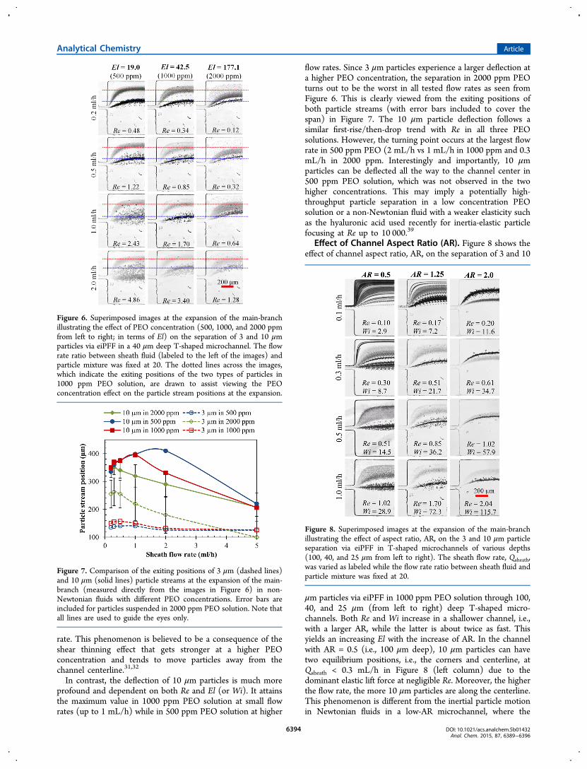
Effect of Channel Aspect Ratio (AR). Figure 8 shows theeffect of channel aspect ratio, AR, on the separation of 3 and 10
μm particles via eiPFF in 1000 ppm PEO solution through 100,40, and 25 μm (from left to right) deep T-shaped micro-channels. Both Re and Wi increase in a shallower channel, i.e.,with a larger AR, while the latter is about twice as fast. Thisyields an increasing El with the increase of AR. In the channelwith AR = 0.5 (i.e., 100 μm deep), 10 μm particles can havetwo equilibrium positions, i.e., the corners and centerline, atQsheath < 0.3 mL/h in Figure 8 (left column) due to thedominant elastic lift force at negligible Re. Moreover, the higherthe flow rate, the more 10 μm particles are along the centerline.This phenomenon is different from the inertial particle motionin Newtonian fluids in a low-AR microchannel, where the
Figure 6. Superimposed images at the expansion of the main-branchillustrating the effect of PEO concentration (500, 1000, and 2000 ppmfrom left to right; in terms of El) on the separation of 3 and 10 μmparticles via eiPFF in a 40 μm deep T-shaped microchannel. The flowrate ratio between sheath fluid (labeled to the left of the images) andparticle mixture was fixed at 20. The dotted lines across the images,which indicate the exiting positions of the two types of particles in1000 ppm PEO solution, are drawn to assist viewing the PEOconcentration effect on the particle stream positions at the expansion.
Figure 7. Comparison of the exiting positions of 3 μm (dashed lines)and 10 μm (solid lines) particle streams at the expansion of the main-branch (measured directly from the images in Figure 6) in non-Newtonian fluids with different PEO concentrations. Error bars areincluded for particles suspended in 2000 ppm PEO solution. Note thatall lines are used to guide the eyes only.
Figure 8. Superimposed images at the expansion of the main-branchillustrating the effect of aspect ratio, AR, on the 3 and 10 μm particleseparation via eiPFF in T-shaped microchannels of various depths(100, 40, and 25 μm from left to right). The sheath flow rate, Qsheath,was varied as labeled while the flow rate ratio between sheath fluid andparticle mixture was fixed at 20.
Analytical Chemistry Article
DOI: 10.1021/acs.analchem.5b01432Anal. Chem. 2015, 87, 6389−6396
6394

particle equilibrium positions are preferably centered at thewider faces in the channel depth direction.15,48,60 A visibleseparation of 10 μm particles from 3 μm particles is achieved atQsheath = 0.5 mL/h (Re = 0.51) and gets better at 1.0 mL/h.This trend is similar to that in the channel with AR = 1.25 (i.e.,40 μm deep, middle column of Figure 8) where the separationis visually better though the deflections of both sizes of particlesare smaller. In contrast, the particle behavior in the channelwith AR = 2.0 (i.e., 25 μm deep) are much more interesting. Asseen from the images in the right column of Figure 8, thedeflection of 10 μm particles can be either smaller (at low flowrates) or larger (at high flow rates) than that of 3 μm particlesdepending on the value of Re. This switch takes place at Qsheath= 0.5 mL/h where Re = 1.02. Such a surprising phenomenonalso occurs for 500 and 2000 ppm PEO solutions in the samechannel (data not shown). It is, however, absent from theparticle motion in Newtonian fluids, where larger particlesalways migrate to the channel centerline faster than smallerones due to the rotation-induced inertial lift force.61 Inaddition, the stream width of each size of particles in the 25μm deep channel seems to be the narrowest among the threechannels due to perhaps the strongest steric effects from thetop/bottom walls therein.Figure 9 compares the exiting positions of 3 and 10 μm
particle streams (with error bars included) at the expansion of
the main-branch in T-shaped microchannels with (A) AR = 0.5(i.e., 100 μm deep) and (B) AR = 2.0 (i.e., 25 μm deep),respectively. These two graphs can be compared directly to thatin Figure 4 for the channel with AR = 1.25 (i.e., 40 μm deep).The deflection of 10 μm particles exhibits a similar trend in allthree depths of channels, which first increases with the rise offlow rate and then decreases at higher flow rates. However, the
maximum deflection decreases from 450 μm (right along thecenterline of the expansion) in the deepest channel to around340 μm in the shallowest channel. While the flow rate at whichthe maximum particle deflection happens seems to remain atapproximately 1 mL/h in all three channels, the slope of thedecreasing particle deflection with flow rate turns out to be thesteepest in the 40 μm deep channel. In contrast, the deflectionof 3 μm particles in the 25 μm-deep channel decreases with theincrease of flow rate, which is apparently different from that inthe two deeper channels.
■ CONCLUSIONSWe have conducted a systematic experimental study of thecontinuous particle separation in PEO solutions via eiPFF. Fivedimensionless numbers, i.e., Re, Wi, El, α, and AR, have beenused to quantify the parametric effects for a fundamentalunderstanding of the important factors in device design andcontrol. We have demonstrated that eiPFF offers a much higherparticle throughput and a much better separation resolutionthan the traditional PFF. Moreover, as it works most efficientlyfor Re of order 1, eiPFF fills perfectly into the gap of ourrecently proposed inertia-enhanced PFF (iPFF) technique56
that requires Re of order 10 or more. This feature makes eiPFFsuitable for particle and cell separation in microfluidic devicesthat typically process a limited amount of samples.62,63 Inaddition, eiPFF has the potential to separate particles of 1 μmdiameter26 or even smaller,34 which is very hard (if notimpossible) for iPFF56 and other inertia-based separationtechniques.15,48 We have also observed two new phenomenathat have not been reported in the literature: one is that theparticle focusing and separation via eiPFF does not increasemonotonically with El at higher PEO concentrations due to themutual influences of elastic and inertial effects; and the other isthat the channel aspect ratio, AR, strongly affects the particleseparation due to its influence on the particle deflection. Moresurprisingly, the elasto-inertial deflection of small particles canbe even greater than that of large ones in a high-AR channelwhen Re is less than 1.
■ ASSOCIATED CONTENT*S Supporting InformationDetails on how to determine the Newtonian and non-Newtonian fluid properties in Table 1 and how to understandeq 6. The Supporting Information is available free of charge onthe ACS Publications website at DOI: 10.1021/acs.anal-chem.5b01432.
■ AUTHOR INFORMATIONCorresponding Author*E-mail: [email protected]. Fax: +1 864 656 5630. Phone:+1 864 656 7299.
NotesThe authors declare no competing financial interest.
■ ACKNOWLEDGMENTSThis work was partially supported by Clemson Universitythrough a departmental SGER (Small Grants for ExploratoryResearch) grant.
■ REFERENCES(1) Pamme, N. Lab Chip 2007, 7, 1644−1659.
Figure 9. Comparison of the exiting positions (symbols with errorbars, measured directly from the images in Figure 8) of 3 and 10 μmparticle streams in 1000 ppm PEO solution at the expansion of themain-branch in T-shaped microchannels with (A) AR = 0.5 (100 μmdeep) and (B) AR = 2.0 (25 μm deep), respectively. The unfilled datapoints in (A) represent a secondary equilibrium position (with fewerparticles present) at the corner of the channel for 10 μm particles.Note that all lines are used to guide the eyes only.
Analytical Chemistry Article
DOI: 10.1021/acs.analchem.5b01432Anal. Chem. 2015, 87, 6389−6396
6395

(2) Gossett, D. R.; Weaver, W. M.; Mach, A. J.; Hur, S. C.; Tse, H.T.; Lee, W.; Amini, H.; Di Carlo, D. Anal. Bioanal. Chem. 2010, 397,3249−3267.(3) Karimi, A.; Yazdi, S.; Ardekani, A. M. Biomicrofluidics 2013, 7,021501.(4) Pethig, R. Biomicrofluidics 2010, 4, 022811.(5) Kim, S. B.; Yoon, S. Y.; Sung, H. J.; Kim, S. S. Anal. Chem. 2008,80, 2628−2630.(6) Ding, X.; Li, P.; Lin, P. S. C.; Stratton, Z. S.; Nama, N.; Guo, F.;Slotcavage, D.; Mao, X.; Shi, J.; Costanzo, F.; Huang, T. J. Lab Chip2013, 13, 3626−3649.(7) Hejazian, M.; Li, W.; Nguyen, N. T. Lab Chip 2015, 15, 959−970.(8) Watarai, H. Annu. Rev. Anal. Chem. 2013, 6, 353−378.(9) Regtmeier, J.; Eichhorn, R.; Viefhues, M.; Bogunovic, L.;Anselmetti, D. Electrophoresis 2011, 32, 2253−2273.(10) Huang, L.; Cox, E. C.; Austin, R. H.; Sturm, J. C. Science 2004,304, 987−990.(11) Yamada, M.; Seki, M. Anal. Chem. 2006, 78, 1357−1362.(12) Choi, S. Y.; Song, S.; Choi, C.; Park, J. K. Anal. Chem. 2009, 81,1964−1968.(13) Giddings, J. C. J. Chromatogr. 1989, 480, 21−33.(14) Yamada, M.; Nakashima, M.; Seki, M. Anal. Chem. 2004, 76,5465−5471.(15) Martel, J. M.; Toner, M. Annu. Rev. Biomed. Eng. 2014, 16, 371−396.(16) Pipe, C. J.; McKinley, G. H.Mech. Res. Commun. 2009, 36, 110−120.(17) Berli, C. L. A. Electrophoresis 2013, 34, 622−630.(18) Zhao, C.; Yang, C. Adv. Colloid Interface Sci. 2013, 201−202,94−108.(19) Karnis, A.; Goldsmith, H. L.; Mason, S. G. Nature 1963, 200,159−160.(20) Karnis, A.; Mason, S. G. Trans. Soc. Rheol. 1966, 10, 571−592.(21) McKinley, G. H. Transport Processes in Bubbles, Drops &Particles, 2nd ed.; Chhabra, R.; D. De Kee, Eds.; Taylor & Francis:New York, 2002; Chapter 14.(22) Leal, G. J. Non-Newton. Fluid Mech. 1979, 5, 33−78.(23) Becker, L. E.; McKinley, G. H.; Rasmussen, H. K.; Hassager, O.J. Rheol. 1994, 38, 377−403.(24) Arigo, M. T.; Mckinley, G. H. Rheol. Acta 1998, 37, 307−327.(25) Leshansky, A. M.; Bransky, A.; Korin, N.; Dinnar, U. Phys. Rev.Lett. 2007, 98, 234501.(26) Kang, K.; Lee, S. S.; Hyun, K.; Lee, S. J.; Kim, J. M. Nat.Commun. 2013, 4, No. 2567, DOI: 10.1038/ncomms3567.(27) Romeo, G.; D’Avino, G.; Greco, F.; Nettiab, P. A.; Maffettone,P. L. Lab Chip 2013, 13, 2802−2807.(28) Ho, B. P.; Leal, L. G. J. Fluid Mech. 1976, 76, 783−799.(29) Huang, P. Y.; Feng, J.; Hu, H. H.; Joseph, D. D. J. Fluid Mech.1997, 343, 73−94.(30) Villone, M. M.; D’Avino, G.; Hulsen, M. A.; Greco, F.;Maffettone, P. L. J. Non-Newton. Fluid Mech. 2011, 166, 1396−1405.(31) Huang, P. Y.; Joseph, D. D. J. Non-Newton. Fluid Mech. 2000, 90,159−185.(32) Seo, K. W.; Byeon, H. J.; Huh, H. K.; Lee, S. J. RSC Adv. 2014,4, 3512−3520.(33) D’Avino, G.; Maffettone, P. L. J. Non-Newton. Fluid Mech. 2015,215, 80−104.(34) Kim, J. Y.; Ahn, S. W.; Lee, S. S.; Kim, J. M. Lab Chip 2012, 12,2807−2814.(35) Seo, K. W.; Kang, Y. J.; Lee, S. J. Phys. Fluid. 2014, 26, 063301.(36) Yang, S. Y.; Kim, J. Y.; Lee, S. J.; Lee, S. S.; Kim, J. M. Lab Chip2011, 11, 266−273.(37) Giudice, F. D.; Romeo, G.; D’Avino, G.; Greco, F.; Netti, P. A.;Maffettone, P. L. Lab Chip 2013, 13, 4263−4271.(38) Lim, H.; Nam, J.; Shin, S. Microfluid. Nanofluid. 2014, 17, 683−692.
(39) Lim, E. J.; Ober, T.; Edd, J. F.; Desai, S. P.; Neal, D.; Bong, K.W.; Doyle, P. S.; McKinley, G. H.; Toner, M. Nat. Commun. 2014, 5,No. 4120, DOI: 10.1038/ncomms5120.(40) Ahn, S. W.; Lee, S. S.; Lee, S. J.; Kim, J. M. Chem. Eng. Sci. 2015,126, 237−243.(41) Cha, S.; Kang, K.; You, J. B.; Im, S. G.; Kim, Y.; Kim, J. M. Rheol.Acta 2014, 53, 927−933.(42) Lee, D. L.; Brenner, H.; Youn, J. R.; Song, Y. S. Sci. Rep. 2013, 3,No. 3258, DOI: 10.1038/srep03258.(43) Cha, S.; Shin, T.; Lee, S. S.; Shim, W.; Lee, G.; Lee, S. J.; Kim,Y.; Kim, J. M. Anal. Chem. 2012, 84, 10471−10477.(44) Seo, K. W.; Ha, Y. R.; Lee, S. J. Appl. Phys. Lett. 2014, 104,213702.(45) Yang, S.; Lee, S. S.; Ahn, S. W.; Kang, K.; Shim, W.; Lee, G.;Hyune, K.; Kim, J. M. Soft Matter 2012, 8, 5011−5019.(46) Geislinger, T. M.; Franke, T. Adv. Colloid Interface Sci. 2014,208, 161−176.(47) Nam, J.; Lim, H.; Kim, D.; Jung, H.; Shin, S. Lab Chip 2012, 12,1347−1354.(48) Amini, H.; Lee, W.; Di Carlo, D. Lab Chip 2014, 14, 2739−2761.(49) Liang, L.; Qian, S.; Xuan, X. J. Colloid Interface Sci. 2010, 350,377−379.(50) Lu, X.; Patel, S.; Zhang, M.; Joo, S.; Qian, S.; Ogale, A.; Xuan, X.Biomicrofluids 2014, 8, 021802.(51) Maenaka, H.; Yamada, M.; Yasuda, M.; Seki, M. Langmuir 2008,24, 4405−4410.(52) Mortensen, N. A. Anal. Chem. 2007, 79, 9240−9241.(53) Jain, A.; Posner, J. D. Anal. Chem. 2008, 80, 1641−1648.(54) Nho, H. W.; Yoon, T. H. Lab Chip 2013, 13, 773−776.(55) Lu, X.; Hsu, J. P.; Xuan, X. Langmuir 2015, 31, 620−627.(56) Lu, X.; Xuan, X. Anal. Chem. 2015, 87, 4560−4565.(57) Lee, K. H.; Kim, S. B.; Lee, K. S.; Sung, H. J. Lab Chip 2011, 11,354−357.(58) Morijiri, M.; Sunahiro, S.; Senaha, M.; Yamada, M.; Seki, M.Microfluid. Nanofluid. 2011, 11, 105−110.(59) Di Carlo, D.; Edd, J. F.; Humphry, K. J.; Stone, H. A.; Toner, M.Phys. Rev. Lett. 2009, 102, 094503.(60) Bhagat, A. A. S.; Kuntaegowdanahalli, S. S.; Papautsky, I. Phys.Fluid. 2008, 20, 101702.(61) Zhou, J.; Papautsky, I. Lab Chip 2013, 13, 1121−1132.(62) Reyes, D. R.; Iossifidis, D.; Auroux, P. A.; Manz, A. Anal. Chem.2002, 74, 2623−2636.(63) Auroux, P. A.; Iossifidis, D.; Reyes, D. R.; Manz, A. Anal. Chem.2002, 74, 2627−2652.
Analytical Chemistry Article
DOI: 10.1021/acs.analchem.5b01432Anal. Chem. 2015, 87, 6389−6396
6396