partial report of ui project
TRANSCRIPT

8/8/2019 Partial Report of UI Project
http://slidepdf.com/reader/full/partial-report-of-ui-project 1/27
A PARTIAL PROJECT REPORT ON
“SPECIFICATION DRIVEN UI FOR
CONTROL & MONITORING SYSTEM”
SUBMITTED TO THE UNIVERSITY OF PUNE, PUNE
IN THE PARTIAL FULFILLMENT OF THE REQUIREMENTS
FOR THE AWARD OF THE DEGREE
OF
BACHELOR OF ENGINEERING
( INFORMATION TECHNOLOGY )
BY
STUDENT NAME ROLL NO
Anuja Jadhav 47061
Kunal Kabare 47070
Akhil Karanth 47073
Mandar Mulay 47096
DEPARTMENT OF INFORMATION TECHNOLOGY
STES’S SINHGAD COLLEGE OF ENGINEERING
VADGAON (BK), OFF SINHGAD ROAD
PUNE - 411041
SCOE, Information Technology, 2010-11
1

8/8/2019 Partial Report of UI Project
http://slidepdf.com/reader/full/partial-report-of-ui-project 2/27
October 2010
CERTIFICATE
This is to certify that the project report entitles
“SPECIFICATION DRIVEN UI
FOR CONTROL AND MONITORING SYSTEM”
Submitted by
Student name Roll. No.Anuja Jadhav 47061Kunal Kabare 47070
Akhil Karanth 47073
Mandar Mulay 47096
is a bonafide work carried out by them under the supervision of Prof. Mrs. S. M. Jaybhaye
and it is approved for the partial fulfillment of the requirement of University of Pune, Punefor the award of the degree of Bachelor of Engineering (Information Technology)
This project work has not been earlier submitted to any other Institute or University for the award of any degree or diploma.
Prof. Mrs. S. M. Jaybhaye Prof. A.W. Rohankar
Guide, Head,Department of Information Technology Department of Information Technology
(Prof. Dr. A.S.Padalkar)
PrincipalSinhgad College of Engineering, Pune-41
Place : PuneDate : 6th October, 2010
SCOE, Information Technology, 2010-11
2
8/8/2019 Partial Report of UI Project
http://slidepdf.com/reader/full/partial-report-of-ui-project 3/27
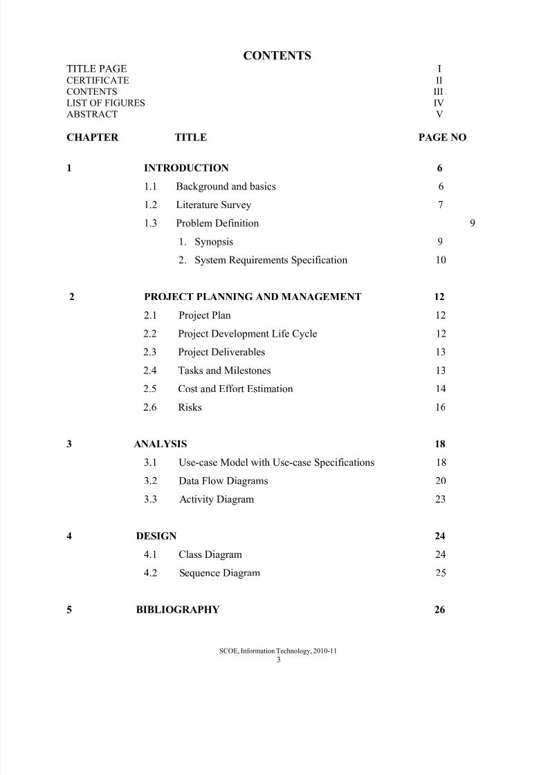
CONTENTS
TITLE PAGE ICERTIFICATE II
CONTENTS III
LIST OF FIGURES IV
ABSTRACT V
CHAPTER TITLE PAGE NO
1 INTRODUCTION 6
1.1 Background and basics 6
1.2 Literature Survey 7
1.3 Problem Definition 9
1. Synopsis 9
2. System Requirements Specification 10
2 PROJECT PLANNING AND MANAGEMENT 12
2.1 Project Plan 12
2.2 Project Development Life Cycle 12
2.3 Project Deliverables 13
2.4 Tasks and Milestones 13
2.5 Cost and Effort Estimation 14
2.6 Risks 16
3 ANALYSIS 18
3.1 Use-case Model with Use-case Specifications 18
3.2 Data Flow Diagrams 20
3.3 Activity Diagram 23
4 DESIGN 24
4.1 Class Diagram 24
4.2 Sequence Diagram 25
5 BIBLIOGRAPHY 26
SCOE, Information Technology, 2010-11
3

8/8/2019 Partial Report of UI Project
http://slidepdf.com/reader/full/partial-report-of-ui-project 4/27
LIST OF FIGURES
FIGURE NO TITLE PAGE NO
1. Project Theme 9
2. Project Plan 12
3. Use Case Diagram (Level 0) 18
4. Use Case Diagram (Level 1) 19
5. Data Flow Diagram (Level 0) 20
6. Data Flow Diagram (Level 1) 21
7. Data Flow Diagram (Level 2) 22
8. Activity Diagram 23
9. Class Diagram 2410. Sequence Diagram 25
SCOE, Information Technology, 2010-11
4
8/8/2019 Partial Report of UI Project
http://slidepdf.com/reader/full/partial-report-of-ui-project 5/27
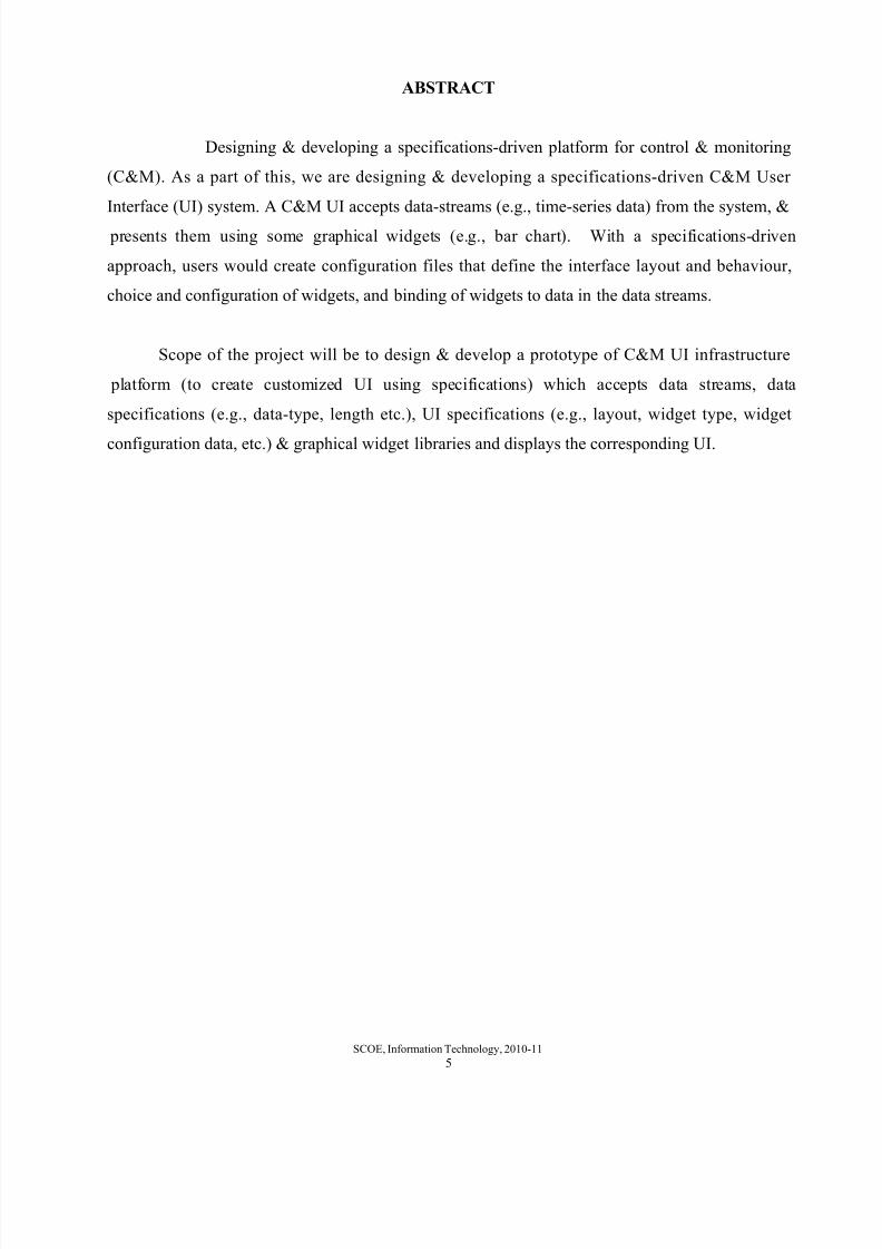
ABSTRACT
Designing & developing a specifications-driven platform for control & monitoring
(C&M). As a part of this, we are designing & developing a specifications-driven C&M User
Interface (UI) system. A C&M UI accepts data-streams (e.g., time-series data) from the system, &
presents them using some graphical widgets (e.g., bar chart). With a specifications-driven
approach, users would create configuration files that define the interface layout and behaviour,
choice and configuration of widgets, and binding of widgets to data in the data streams.
Scope of the project will be to design & develop a prototype of C&M UI infrastructure
platform (to create customized UI using specifications) which accepts data streams, data
specifications (e.g., data-type, length etc.), UI specifications (e.g., layout, widget type, widget
configuration data, etc.) & graphical widget libraries and displays the corresponding UI.
SCOE, Information Technology, 2010-11
5

8/8/2019 Partial Report of UI Project
http://slidepdf.com/reader/full/partial-report-of-ui-project 6/27
CHAPTER 1
INTRODUCTION
1.1 BACKGROUND AND BASICS
In the developed world, information technology is being embedded into more and more
everyday items, and many people are increasingly reliant on electronically delivered information
and services. At the same time, there is an explosion in the diversity of devices with which
individuals access these electronic services. Laptops, personal digital assistants and cell phones are
the prototypical examples of personal access devices, but the range of delivery platforms is
expanding, both in terms of input (e.g. handwriting recognition, speech and gesture) and output
capabilities (e.g. very large displays, headmounted reality augmentation displays).
To handle this diversity, service providers must either devote considerable resources to
developing multiple alternative user interfaces, each specialized to a particular context of use, or
must develop more flexible user interfaces. This problem has sparked a resurgence of interest in
the use of design and layout specifications from the user. It should ideally provide all of the
service-specific information necessary to build a user interface for any user. Given a sufficiently
expressive abstract representation of a service, user interfaces for multiple contexts could be
developed quickly, using support tools. They could even be generated entirely automatically.
However, providing a remote interface cannot be a substitute for the use of inclusive, universal
design techniques to accommodate as wide a range of users and contexts as possible in built-in
user interfaces, as not all users will carry a mobile user interface device with them all the time.
Abstract representations do not capture all of the information that a human designer would
use in creating a high quality user interface, so generated user interfaces based on such
representations would typically be less polished. This approach is of most benefit to users whose
needs are not served by the built-in user interface, and anyone who would find an alternative or
remote interface to be of value, but whose representation in the market is not seen as profitable
enough by the product vendor to provide a specialized user interface for their user group.
SCOE, Information Technology, 2010-11
6

8/8/2019 Partial Report of UI Project
http://slidepdf.com/reader/full/partial-report-of-ui-project 7/27
Many organizations are actively developing abstract languages and frameworks for user
interface representation. If these technologies provided the right features, their adoption would
present a significant opportunity to advance universal usability. This article describes and uses the
concept of a universal remote console (URC) as a motivating scenario, and discusses the usability
benefits and costs of using abstract interface descriptions in this context. It presents some desirable
properties of a language supporting this scenario and identifies technical requirements that are
imposed on abstract languages and the architectures in which they are embedded.
1.2 LITERATURE SURVEY
1.2.1 References
• JfreeChart Library Documentation
This documentation gives an idea about the classes and methods to be used for
drawing different types of graphs and charts in java like line graph ,bar graph etc. This
also gives details on how to make the graphs dynamic and show real time data.
• XML 1.1 Bible
This gives information on the different design techniques to design a XML
specification file.
• UIML
UIML stands for "User Interface Markup Language." UIML is an XML
language for defining user interfaces.Most XML languages are used for defining
documents. In other words, they allow programs to break up alot of words, pictures and
other data into useful chunks that can be processed by a program.UIML, on the other
hand is used for defining the actual interface elements. This means the buttons, menus,
lists and other controls that allow a program to function in a graphical interface like
Windows or Motif. UIML is used to define the location, and design of controls. It also
defines actions to take when certain events take place. Users create events when they
interact with the interface by typing a key on the keyboard or moving and clicking the
mouse.
SCOE, Information Technology, 2010-11
7

8/8/2019 Partial Report of UI Project
http://slidepdf.com/reader/full/partial-report-of-ui-project 8/27
• Science-Direct paper
Abstract Representations as a basis for Usable user interfaces
This article examines four existing or proposed standards for abstract description
of user interfaces: UIML, XIML, XForms and URC. These are assessed with respect to
a ‘universal remote console’ scenario, in which abstract user interface descriptions
enable any user to access and control any compliant device or service in the local
environment, using any personal device. Achieving usable interfaces in this scenario
requires an abstract language that (a) separates data from presentation; (b) explicitly
declares interface elements, their state, dependencies, and semantics;(c) incorporates
alternative resources in a flexible way; and (d) supports remote control and differentinteraction styles. Of the technologies examined, XForms and URC provide the best
match to the requirements. While XForms requires an appropriate context of use to
provide full access, the URC standard will include specification of the context in which
the language is to be used. Two specific research challenges are identified: semantic
tagging and the development of effective authoring processes.
1.2.2 Existing Works
• FlyCharts
1.2.3 Details of Same kind of work
• FlyCharts component is Flash-based technology. Data and component visual style
comes from customizable XML file. Both component and XML file are placed on the
web server-side.When user opens a webpage with a component, FlyCharts is being
loaded with XML data attached. All the processing of data goes on browser (user) side,
so no server CPU loading.
SCOE, Information Technology, 2010-11
8
8/8/2019 Partial Report of UI Project
http://slidepdf.com/reader/full/partial-report-of-ui-project 9/27
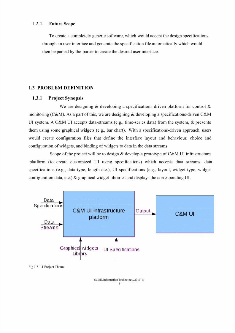
1.2.4 Future Scope
To create a completely generic software, which would accept the design specifications
through an user interface and generate the specification file automatically which would
then be parsed by the parser to create the desired user interface.
1.3 PROBLEM DEFINITION
1.3.1 Project Synopsis
We are designing & developing a specifications-driven platform for control &
monitoring (C&M). As a part of this, we are designing & developing a specifications-driven C&MUI system. A C&M UI accepts data-streams (e.g., time-series data) from the system, & presents
them using some graphical widgets (e.g., bar chart). With a specifications-driven approach, users
would create configuration files that define the interface layout and behaviour, choice and
configuration of widgets, and binding of widgets to data in the data streams.
Scope of the project will be to design & develop a prototype of C&M UI infrastructure
platform (to create customized UI using specifications) which accepts data streams, data
specifications (e.g., data-type, length etc.), UI specifications (e.g., layout, widget type, widget
configuration data, etc.) & graphical widget libraries and displays the corresponding UI.
Fig 1.3.1.1 Project Theme
SCOE, Information Technology, 2010-11
9

8/8/2019 Partial Report of UI Project
http://slidepdf.com/reader/full/partial-report-of-ui-project 10/27
1.3.2 System Requirements Specification
1. Introduction
A. Problem Statement
To design and develope a specifications-driven platform for control & monitoring
system. We are designing & developing a specifications-driven C&M User Interface system for
the scientific instruments.
B. Scope of The System
Scope of the project will be to design & develop a prototype of C&M UIinfrastructure platform (to create customized UI using specifications) which accepts data streams,
data specifications (e.g., data-type, length etc.), UI specifications (e.g., layout, widget type, widget
configuration data, etc.) & graphical widget libraries and displays the corresponding UI.
2. Proposed System
The user will provide the design specifications like the choice and configuration
of the widgets in the form of an XML file, while the real time data is coming from the server. The
parser will will read the XML specification file and generate the screen layout. And the data
received from the server is represented in the form of line graphs, bar charts, pie charts, etc.
3. Project Status
SCOE, Information Technology, 2010-11
10

8/8/2019 Partial Report of UI Project
http://slidepdf.com/reader/full/partial-report-of-ui-project 11/27
3.1 Classification
Specification driven real time system system
3.2 Definition
To represent the real time data from the various scientific instruments in the
form of graphical widgets.
3.3 Responsibilities
To accept the real time data from the data server and design specifications from
the user and create the interface layout based on the design specifications and represent
the data in the form of graphical widgets
3.4 Composition
The system will consistes of the following things :a. Data server generating data
b. Client accepting the data from the server and design specifications from user
c. The parser to parse the XML specification file
4. Requirement
4.1 Software Requirements
1. Java
2. JavaScript/AJAX
3. XML
4. HTML/CSS
4.2 Hardware Requirements
Desktop/Server workstation
4.3 Operating SystemLinux/Windows
4.4 Network requirement
Yes
SCOE, Information Technology, 2010-11
11

8/8/2019 Partial Report of UI Project
http://slidepdf.com/reader/full/partial-report-of-ui-project 12/27
5. Expected date of Completion
5th March, 2011
CHAPTER 2
PROJECT PLANNING AND MANAGEMENT
2.1 PROJECT PLAN
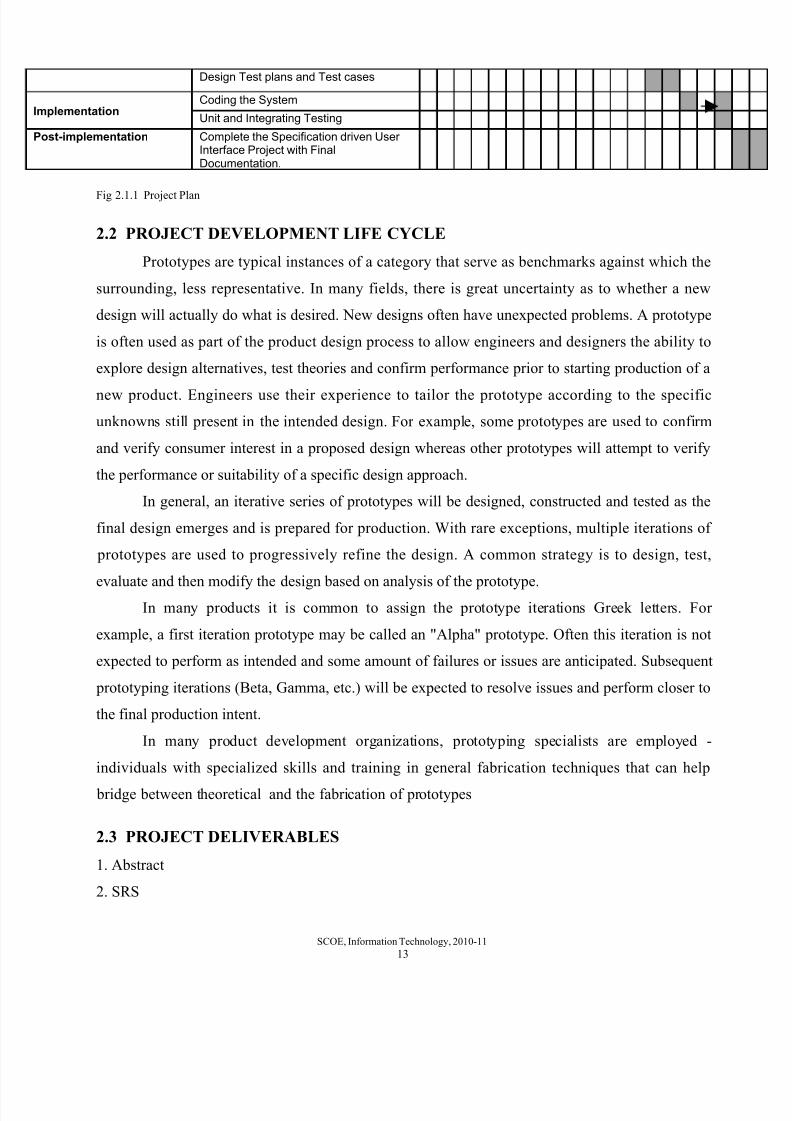
Activity↓ Week→ 1 2 3 4 5 6 7 8 9 10
11
12
13
14
15
16
25
Requirements and
Planning
Discussion on Requirements
Prepare the Requirement documents
Prepere the Project plan
Optimize and Finalize the project plan
Documentation
Perform the Structural Analysis
Create Various Structural diagrams
Perform the Behavioral Analysis
Draw the Behavioral Diagrams
Design Prepare the tool design
Write Functional ( XML file)specifications
Design Prototype Screen
SCOE, Information Technology, 2010-11
12
8/8/2019 Partial Report of UI Project
http://slidepdf.com/reader/full/partial-report-of-ui-project 13/27
Design Test plans and Test cases
ImplementationCoding the System
Unit and Integrating Testing
Post-implementation Complete the Specification driven User Interface Project with FinalDocumentation.
Fig 2.1.1 Project Plan
2.2 PROJECT DEVELOPMENT LIFE CYCLE
Prototypes are typical instances of a category that serve as benchmarks against which the
surrounding, less representative. In many fields, there is great uncertainty as to whether a new
design will actually do what is desired. New designs often have unexpected problems. A prototype
is often used as part of the product design process to allow engineers and designers the ability to
explore design alternatives, test theories and confirm performance prior to starting production of a
new product. Engineers use their experience to tailor the prototype according to the specific
unknowns still present in the intended design. For example, some prototypes are used to confirm
and verify consumer interest in a proposed design whereas other prototypes will attempt to verify
the performance or suitability of a specific design approach.
In general, an iterative series of prototypes will be designed, constructed and tested as the
final design emerges and is prepared for production. With rare exceptions, multiple iterations of
prototypes are used to progressively refine the design. A common strategy is to design, test,
evaluate and then modify the design based on analysis of the prototype.In many products it is common to assign the prototype iterations Greek letters. For
example, a first iteration prototype may be called an "Alpha" prototype. Often this iteration is not
expected to perform as intended and some amount of failures or issues are anticipated. Subsequent
prototyping iterations (Beta, Gamma, etc.) will be expected to resolve issues and perform closer to
the final production intent.
In many product development organizations, prototyping specialists are employed -
individuals with specialized skills and training in general fabrication techniques that can help
bridge between theoretical and the fabrication of prototypes
2.3 PROJECT DELIVERABLES
1. Abstract
2. SRS
SCOE, Information Technology, 2010-11
13

8/8/2019 Partial Report of UI Project
http://slidepdf.com/reader/full/partial-report-of-ui-project 14/27
3. Prototyping Model
4. UML diagrams
5. XML files including all Specifications
6. UI engine generating GUI
7. XML files generated using various GUI`s
2.4 TASKS AND MILESTONES
The entire development life cycle of the project entails performing many tasks. Also, certain
milestones are set and reached, indicating correct and timely progress . All these adhere to the
formulated project plan.
The important tasks carried out in the course of completion of this project are requirements
gathering, analysis of the requirements, designing a prototype, designing the user interface for the
server data and testing the project.
The Milestones are :
1. Completion of Preliminary Requirements
2. Completion of Prototype design3. Completion of Preliminary Documents
4. Completion of XML file specification
5. Completion of integration of XML files with GUI
6. Completion of various components of the project into one deliverable application.
7. Completion of development of a sample application which demonstrates the framework
2.5 COST AND EFFORT ESTIMATION
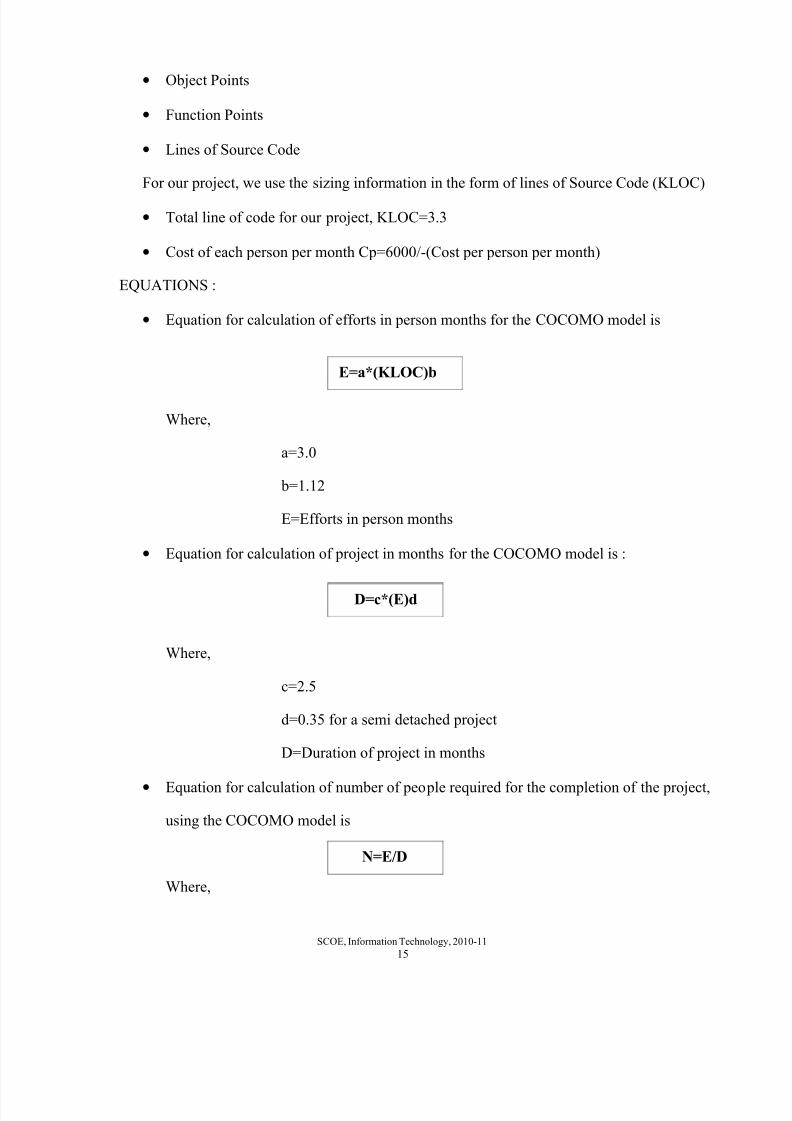
The constructive Cost Model (COCOMO) is generally used for estimation measures of
cost, project duration, manpower, etc. Like all estimation models COCOMO model requires sizing
information. The information can be specified in the form of Object Points
SCOE, Information Technology, 2010-11
14
8/8/2019 Partial Report of UI Project
http://slidepdf.com/reader/full/partial-report-of-ui-project 15/27
• Object Points
• Function Points
• Lines of Source Code
For our project, we use the sizing information in the form of lines of Source Code (KLOC)
• Total line of code for our project, KLOC=3.3
• Cost of each person per month Cp=6000/-(Cost per person per month)
EQUATIONS :
• Equation for calculation of efforts in person months for the COCOMO model is
Where,
a=3.0
b=1.12
E=Efforts in person months
• Equation for calculation of project in months for the COCOMO model is :
Where,
c=2.5
d=0.35 for a semi detached project
D=Duration of project in months
• Equation for calculation of number of people required for the completion of the project,
using the COCOMO model is
Where,
SCOE, Information Technology, 2010-11
15
E=a*(KLOC)b
D=c*(E)d
N=E/D

8/8/2019 Partial Report of UI Project
http://slidepdf.com/reader/full/partial-report-of-ui-project 16/27
N=Number of people required
E=Efforts in person month
D=Duration of project in months
• Equation for calculation of cost of project using COCOMO model is
Where,
C=Cost of the project
D=Duration of project in months
Cp=Cost incurred per person month
• Efforts
E=3.0(3.6)^1.12
E=14.36 person-month
• Duration of project
D=2.5*(E)^0.35
D=3.5 Months
The approximate duration of the project is 3.32 months.
• The number of people required for the project :
N=14.36/3.5
N=4.11
N=4+people
Therefore, more than 4 people are required to successfully complete the project
on schedule
SCOE, Information Technology, 2010-11
16
C=D*Cp

8/8/2019 Partial Report of UI Project
http://slidepdf.com/reader/full/partial-report-of-ui-project 17/27
• Cost of project :
C=4.11*6000
C=24660
Therefore the cost of the project is Rs 24660/- approximately
2.6 RISKS
2.6.1 Security Risks
1. Eavesdropping
The data transferred by one process can be read by the attacker before it reaches the
other process
2. Data modification
After an attacker has read your data, the next logical step is to alter it. An attacker
can modify the data in the packet without the knowledge of the sender or receiver. Even if
you do not require confidentiality for all communications, you do not want any of your
messages to be modified in transit.
2.6.2 Load on Server
If the server is already serving some request, then it’s not possible at the same time
to serve another request generated by the client
2.6.3 System Failure
If in between the data transfer, the machine fails, the corresponding data is lost.
And it is very tedious to recover the data.
2.6.4 Flow Control
The speed of the server sending the data should not be larger than that of the client,
receiving the data. Otherwise, the client will get flooded.
SCOE, Information Technology, 2010-11
17
8/8/2019 Partial Report of UI Project
http://slidepdf.com/reader/full/partial-report-of-ui-project 18/27
CHAPTER 3
ANALYSIS
3.1 USE CASE DIAGRAMS
3.1.1 Use Case Diagram (Level 0)
SCOE, Information Technology, 2010-11
18

8/8/2019 Partial Report of UI Project
http://slidepdf.com/reader/full/partial-report-of-ui-project 19/27
Fig 3.1.1 Use Case Diagram (Level 0)
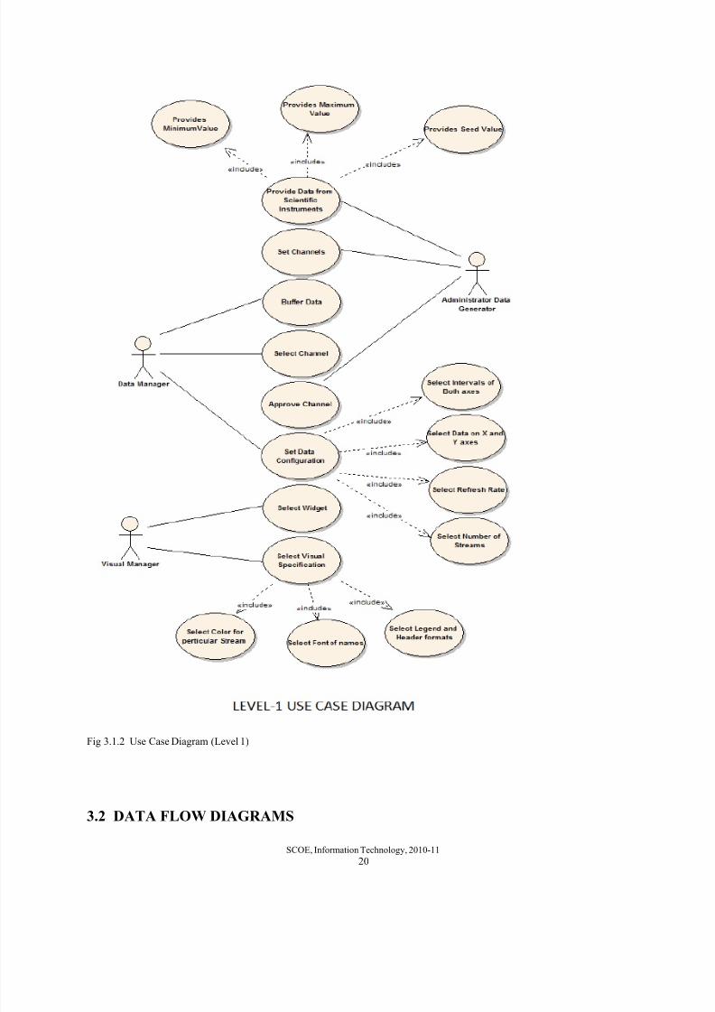
3.1.2 Use Case Diagram (Level 1)
SCOE, Information Technology, 2010-11
19
8/8/2019 Partial Report of UI Project
http://slidepdf.com/reader/full/partial-report-of-ui-project 20/27
Fig 3.1.2 Use Case Diagram (Level 1)
3.2 DATA FLOW DIAGRAMS
SCOE, Information Technology, 2010-11
20

8/8/2019 Partial Report of UI Project
http://slidepdf.com/reader/full/partial-report-of-ui-project 21/27
3.2.1 Data Flow Diagram (Level 0)
Fig 3.2.1 Data Flow Diagram (Level 0)
3.2.2 Data Flow Diagram (Level 1)
SCOE, Information Technology, 2010-11
21

8/8/2019 Partial Report of UI Project
http://slidepdf.com/reader/full/partial-report-of-ui-project 22/27
Fig 3.2.2 Data Flow Diagram (Level 1)
3.2.3 Data Flow Diagram (Level 2)
SCOE, Information Technology, 2010-11
22

8/8/2019 Partial Report of UI Project
http://slidepdf.com/reader/full/partial-report-of-ui-project 23/27
Fig 3.2.3 Data Flow Diagram (Level 2)
3.3 ACTIVITY DIAGRAM
SCOE, Information Technology, 2010-11
23

8/8/2019 Partial Report of UI Project
http://slidepdf.com/reader/full/partial-report-of-ui-project 24/27
Fig 3.3.1 Activity Diagram
CHAPTER 4
SCOE, Information Technology, 2010-11
24

8/8/2019 Partial Report of UI Project
http://slidepdf.com/reader/full/partial-report-of-ui-project 25/27
DESIGN
4.1 CLASS DIAGRAM
Fig 4.1.1 Class Diagram
4.2 SEQUENCE DIAGRAM
SCOE, Information Technology, 2010-11
25

8/8/2019 Partial Report of UI Project
http://slidepdf.com/reader/full/partial-report-of-ui-project 26/27
Fig 4.2.1 Sequence Diagram
CHAPTER 5
BIBILOGRAPHY
SCOE, Information Technology, 2010-11
26

8/8/2019 Partial Report of UI Project
http://slidepdf.com/reader/full/partial-report-of-ui-project 27/27
• A Science Direct research paper on “Abstract representations as a basis for usable user
interfaces” by Shari Trewina, Gottfried Zimmermannb, Gregg Vanderheidenb
•Distillation Monitoring and Control using LabVIEW and SIMULINK Tools byJ. Fernandez de Canete, P. Del Saz Orozco and S. Gonzalez-Perez
• IAA RAS Radio Telescope Monitoring System by Dr. Mikhailov Andrey, Lavrov Alexey
of Institute of Applied Astronomy, Russian Academy of Science St-Petersburg Russia
• The JFreeChart Class Library Version 1.0.4 Developer Guide by David Gilbert
February 9, 2007
• The Large Millimeter Telescope Monitor & Control System by Kamal Souccar, Gary
Wallace, and Daniella Malin of Department of Astronomy, University of Massachusetts,
Amherst, MA 01003, USA, November 29, 2004