part b: common elements - health in wales 01-01 part b.pdf · part b: common elements. ... •...
TRANSCRIPT
WHTM 01-01Welsh Health Technical Memorandum
Decontamination of medical devices within acute services
Part B: Common elements

Disclaimer
The contents of this document are provided by way of general guidance only at the time of its publication. Any partymaking any use thereof or placing any reliance thereon shall do so only upon exercise of that party’s own judgementas to the adequacy of the contents in the particular circumstances of its use and application. No warranty is given asto the accuracy, relevance or completeness of the contents of this document and NHS Wales Shared ServicesPartnership – Facilities Services shall have no responsibility for any errors in or omissions therefrom, or any use madeof, or reliance placed upon, any of the contents of this document.
Note: Heath Building Notes (HBNs) and Health Technical Memoranda (HTMs) issued by the Department ofHealth in England are being superseded by specific Welsh editions which will be titled Welsh Heath Building Notes(WHBNs) and Welsh Health Technical Memoranda (WHTMs). Until this process is complete, where a WHBN orWHTM is referred to in the text but has not yet been published, refer to the relevant publications page on the NHSWales Shared Services Partnership – Facilities Services website for the latest approved document.
Intranet: howis.wales.nhs.uk/whe
Internet: www.wales.nhs.uk/whe
Published by NHS Wales Shared Services Partnership – Facilities Services
This guidance is based on the Choice Framework for local Policy and Procedures (CFPP) 01-01 Part B Common elementsguidance published by the Department of Health
This publication can be accessed from the NHS Wales Shared Services Partnership – Facilities Services websitewww.wales.nhs.uk/whe
ISBN 978-1-909899-00-1
© Copyright NHS Wales Shared Services Partnership – Facilities Services 2013
Cover image by courtesy of NWSSP-FS
Cover designed by Keith James
2
Welsh Health Technical Memorandum 01-01 - Decontamination of medical devices within acute services. Part B: Common elements

3
Overview
Scope of Welsh Health TechnicalMemorandum 01-01 Parts A to EWelsh Health Technical Memorandum (WHTM) 01-01gives guidance on the whole decontamination cycleincluding the management and decontamination ofsurgical instruments used in acute care.
Part A covers the policy, management approach andchoices available in the formulation of a locallydeveloped, risk-controlled operational environment. Thetechnical concepts are based on British (BS), European(EN) and International (ISO) Standards used alongsidepolicy and broad guidance. In addition to the preventionof transmission of conventional pathogens, precautionarypolicies in respect of human prion diseases includingvariant Creutzfeldt-Jakob disease (vCJD) are clearlystated. Advice is also given on surgical instrumentmanagement related to surgical care efficiencies andcontingency against perioperative non-availability ofinstruments.
The management of decontamination equipment is acritical engineering service.
WHTM 01-01 Part A provides a description of theoverall structure of the guidance and the rationalebehind the following:
• the regulatory framework;
• roles of key personnel;
• procedures for the reporting of adverse incidentsand defective equipment;
• local reprocessing (decontamination in primarycare, and local decontamination);
• the management of instruments potentiallycontaminated with transmissible spongiformencephalopathy (TSE) infectivity.
Part B covers common elements that apply to allmethods of surgical instrument reprocessing such as:
• test equipment and materials;
• design and pre-purchase considerations;
• validation and verification.
Part C covers standards, technical guidance, operationalrequirements, and testing and validation protocols whenusing steam for sterilization within the acute care setting.
Part D covers standards, technical guidance, operationalrequirements, and testing and validation protocols whenusing washer-disinfectors as part of the decontaminationcycle within the acute care setting.
Part E covers non steam sterilization processes (such asthe use of vapourised hydrogen peroxide gas plasmas andethylene oxide exposure.) for sterilization fordecontamination providers for the acute care setting.
WHTM 01-01 Part A supersedes Health TechnicalMemorandum 01-01 Part A (Welsh edition 2010).
WHTM 01-01 Parts B–E supersede Health TechnicalMemoranda 2010, 2030 and 2031.
Who should use WHTM 01-01 Part B Part B is intended to cover ‘common elements’ thatwould be applicable to all Parts issued in the WHTM01-01 series. This guidance is designed for technicalpersonnel responsible for validation protocols, and alsofor users responsible for the day-to-day running ofdecontamination equipment. It will also be of interest tomicrobiologists, infection control officers, architects,planners, estates managers, supplies officers, and othersin both the public and private sectors.
Acknowledgements
Listed below are the contributors to the CFPPguidance 01-01 Part B originally included as webcontent in Space for Health within the Departmentof Health (England) part of the site. That guidanceprovided the basis for this Welsh Health TechnicalMemorandum.
Brian Kirk IHEEM Decontamination TechnologyPlatform
Geoffrey L. Ridgway, OBE, MD Clinical Microbiologist
Graham Stanton NHS Wales Shared ServicesPartnership – Facilities Services
Jackie Duggan Health Protection Agency
Jimmy Walker Health Protection Agency
Ken Toal Health Estates, Northern Ireland
Margaret Hollis Great Ormond Street Hospital
Mike Painter Public Health Physician
Mike Simmons Public Health Wales
Peter Hoffman Health Protection Agency
Robert Kingston IHEEM Decontamination TechnologyPlatform
Listed below are the contributors to this WelshHealth Technical Memorandum who sit on the HTMGuidance Peer Group as directed by the WelshGovernment’s All Wales Decontamination Group.
Jenny Thorne Welsh Government
Tracey Gauci Welsh Government
Mike Simmons Public Health Wales
Eric Thomas NHS Wales Shared Services Partnership –Facilities Services
Graham Stanton NHS Wales Shared ServicesPartnership - Facilities Services
John Prendergast NHS Wales Shared ServicesPartnership - Facilities Services
Peter Wiles NHS Wales Shared Services Partnership -Facilities Services
4
5
AE(D): Authorising Engineer (Decontamination)
AP(D): Authorised Person (Decontamination)
BPR: Batch process record
BS: British Standard
CMO: Chief Medical Officer
CP(D): Competent Person (Decontamination)
DH: Department of Health
DE (W): Decontamination Engineer (Wales)
EN: European norm
Hz: Hertz (Unit of frequency)
ISO: International Standards Organisation
IQ: Installation qualification
kPa: Kilopascal (Unit of pressure)
MHRA: Medicines and Healthcare products RegulatoryAgency
MPR: Master Process Record
NICE: National Institute for Health and ClinicalExcellence
NWSSP-FS NHS Wales Shared Services Partnership –Facilities Services
NWSSP-PS NHS Wales Shared Services Partnership –Procurement Services
OQ: Operational qualification
PQ: Performance qualification
QMS: quality management system
RO: Reverse Osmosis
SSD: Sterile Services Department
TSEs: Transmissible spongiform encephalopathies
TST: Technical Specification Template
UKAS: United Kingdom Accreditation Service
WEEE: Waste Electrical Electronic Equipment
WHTM: Welsh Health Technical Memorandum
Abbreviations
Contents
Overview 3Scope of Welsh Health Technical Memorandum 01-01 Parts A to EWho should use WHTM 01-01 Part B
Acknowledgements 4
Abbreviations 5
Chapter 1 Scope and introduction 9GeneralMedical devicesDefinitions
Chapter 2 Decontamination equipment: test equipment and materials 10General considerations Calibration and sources of error Data recorders Temperature measurement
Temperature sensors Thermometric recording instrument(s) Use of sensors Instrument verification Self-contained systems
Pressure measurement Measurement ranges Sensors and gauges
Flow measurement Water Chemical additives Volume measurement
Other instruments Sound level meter Airflow metering device Balance Gas-monitoring equipment Aerosol generatorParticle-counting photometer
Chapter 3 Design and pre-purchase considerations 16Pre-purchase considerations
Introduction Specialist advice Quality systems
6

Product listing Spatial requirements Machine configuration Protein removal and protein optimisation Specification preparation
Procurement of equipment – an overview Introduction Purchasing decontamination equipment
Choice of equipment Introduction Choice of equipment Sizes and numbers
Specification and contract Preparing a specificationGeneral design considerations Safety features Instrumentation Programmable electronic systems Doors Invitation to tenderContract Delivery Siting
Engineering services Introduction Electricity Compressed air Drainage Ventilation
Information to be supplied by the manufacturer
Chapter 4 Validation and verification 25General Permit-to-work Testing of decontamination equipmentResponsibilities
General Responsible Persons
Works tests Validation
Installation qualification Operational qualification Performance qualification (PQ)
Loading Documentation
Summary sheets Validation report
Periodic tests Revalidation Repeat validation Types of test
7
Contents
Procedure on failure of a test Principles of installation and operational tests Principles of performance qualification tests
Loading conditions PQ reportUnderstanding of condensate control in a porous load sterilizerThe use of metal containers within the decontamination processLoading carriages
Product release Tests for performance requalification (PRQ)
References 36
8
Welsh Health Technical Memorandum 01-01 - Decontamination of medical devices within acute services. Part B: Common elements
General1.1 WHTM 01-01 Part B covers the common
elements that are appropriate when operatingvarious types of decontamination equipment usedto decontaminate medical devices in accordancewith harmonised standards. Additionally, itcontains guidance on general designconsiderations, safety requirements and how toprepare a specification for formal procurementprocess.
1.2 The technical concepts are based on British (BS),European (EN) and International (ISO) Standardsused alongside policy and broad guidance.
Note
All general information relating to non-specificlegislation previously included in the Welsh HealthTechnical Memoranda is covered in Welsh HealthTechnical Memorandum 00 to avoid duplication andfor ease of access.
Medical devices 1.3 This guidance covers the various types of
decontamination equipment to be used for thereprocessing of medical devices (for example,porous load sterilizers and washer-disinfectors).
1.4 Guidance on the application of medical deviceslegislation is beyond the scope of this guidance,and advice should be sought from the Medicinesand Healthcare products Regulatory Agency(MHRA).
Definitions1.5 For definitions of terms used in this guidance, see
ISO 11139:2006 ‘Sterilization of health careproducts – vocabulary’.
9
Chapter 1 Scope and introduction
General considerations 2.1 This section reviews the key items of portable test
equipment necessary to carry out the test proceduresdescribed in this guidance. Specifications forinstruments fitted permanently to decontaminationequipment are given in the relevant British,European and International Standards.
2.2 for Technical Specification Templates refer toparagraph 3.1 of this guidance.
2.3 Instrumentation technology continues to advancerapidly, making it increasingly difficult andundesirable to provide detailed specifications forthe equipment to be used in testing equipment.There is a clear trend towards computer-controlleddata recorders with software, which enables thesystem to verify attainment of the requiredconditions and then to produce a detailed writtenreport accompanied by tabulated or graphed data.Although these new systems may offer advantagesin clarity of presentation, as well as reducedoperator time, the traditional instruments, such aschart recorders, remain equally acceptable wherethey meet the accuracy defined in this section.
Note
Retention of data for long-term use is important.Where modern technology/data-recording equipmentis used, it should be equipped with memory devicesthat enable data to be retrieved at a later date.Traditional chart recorders allow the retention of thechart for long-term storage and follow-up.
2.4 The objectives of this section are both to ensurethat traditional measurement methods aresupported adequately and to define clearly theessential requirements that apply to the testequipment whether it is a traditional system or thelatest technology.
2.5 When it is proposed to use measurement and/orrecording techniques that are not covered in thisguidance, the advice of the Authorising Engineer(Decontamination) should be sought.
2.6 All test equipment should be calibrated by aUKAS-accredited laboratory in accordance with
ISO/IEC 17025, with traceability to the NationalStandard.
Calibration and sources of error 2.7 Errors of measurement occur for a number of
reasons. These include inherent factors such as thedesign of the measuring equipment, commonproblems with sensors (such as loose or imperfectconnections), damaged insulation, and brokenconductors, combined with changes in theenvironmental temperature around the instrument.Variations in the sensors themselves, the method ofintroducing the sensors into the machine and theirlocation within the load may add to the error inthe temperature measurement. Changes inconditions other than the one being sensed mayalso lead to errors, for example, temperaturefluctuations within pressure-sensing elements maylead to errors in pressure measurement
2.8 Careful attention to detail including the locationof the test instruments, effective maintenance andthe skill of personnel trained in the application,handling and use of the instruments are requiredto eliminate or minimise these errors. Systematicerrors can be reduced by careful calibration.
2.9 Instruments should be subject to a plannedmaintenance and calibration programme, inaccordance with the instrument manufacturer’srecommendations, occurring at least annually.Each instrument should be labelled with acalibration date and a reference from which itscurrent calibration status may be traced.
2.10 Instrument calibration should be carried out inaccordance with the instrument manufacturer’sinstructions by a validated method, using areference standard of suitable accuracy that hasbeen certified within the previous 12 months by aUKAS test laboratory. The calibration laboratoryshould be instructed to adjust the instrumentunder test to read true values, and to reportbefore and after calibration results so thatinstrument drift can be monitored. A full historyrecord, including all maintenance and calibrationdetails, should be kept for each instrument.
10
Chapter 2 Decontamination equipment: test equipment and materials
2.11 The instrument should have a valid test certificateand the calibration data should include atemperature within the process temperature band.
2.12 In use, all test instruments should be located in aposition protected from draughts and notsubjected to rapid temperature variations. Testinstruments should be allowed a period of time tostabilise within the environment of the test site.The manufacturer’s instructions should befollowed.
Data recorders 2.13 Test recorders are required to measure temperature
in all types of decontamination equipment andmay also be required for the measurement ofpressure, flow rates, and other critical parameters.They should be designed for use with theappropriate sensors, independent of those fitted tothe machine.
2.14 Sufficient connections to meet the testingrequirements of the relevant WHTM section andEN standard should be provided.
2.15 Recorders should comply with the requirements ofBS EN 285 or BS EN ISO 15883.
2.16 Data from digital recorders (data loggers) can bepresented graphically or as a listing of numericalvalues, or as a combination of both. In manycases, parts of the operating cycle can be expandedand re-plotted for closer examination.
2.17 Digital recorders should have the facility to recorddata immediately that can then be removed forsecure storage. Alternatively, the recorder may beconnected to a central computer and the datarecorded to the hard drive. Software used withdigital recorders should be developed and validatedunder a recognised quality system (see BS EN ISO13485).
2.18 The detailed specification for a test recorder willdepend upon the range of equipment with whichit is to be used. The measurement system (recorderand sensors) should be capable of measuring cyclevariables to the required accuracy of theinstruments fitted to the machine.
2.19 The accuracy with which a variable can be readfrom the recorder will be affected not only by thesources of error discussed above but also by theprecision of the calibration, the scale range, theintegration time, the sampling interval and theintrinsic accuracy of the recorder. Digitalinstruments might display measured values with agreater level of discrimination than the accuracy ofthe system as a whole: care needs to be taken with
the configuration of outputs and the interpretationof the measured values.
2.20 The accuracies quoted by recorder manufacturersare measured under controlled referenceconditions and do not include the errors fromconnected sensors. Temperature measurementerrors due to ambient temperature changes shouldnot exceed 0.04˚C per ˚C rise. The system shouldbe calibrated as a whole also.
2.21 The scale ranges should include the expectedmaximum and minimum values of the cyclevariables throughout the operating cycle, withsufficient leeway to accommodate any deviationsresulting from a malfunctioning machine.
2.22 At all stages of the cycle, the values of the variablesare critical and the recorder should be capable ofmeasuring them to sufficient accuracy to confirmthat the process conditions have been attained.The criteria are as follows:
1. For digital recorders, the sampling intervalshould be short enough for the holding time tocontain at least 180 independent measurementsin each recording channel. This corresponds toa sampling interval of one second for theshortest holding time (three minutes, high-temperature steam sterilizers) for periodictesting. For pen recorders, the chart speedshould be fast enough to allow fluctuations onthat scale to be clearly resolved. The duration ofthe holding time should be measurable towithin 1%.
2. The integration time of the recorder (theresponse time) should be short enough toenable the output to follow significantfluctuations in the cycle variables and to ensurethat successive measurements are independentof each other. It should not be longer than thesampling interval.
3. The recorder should be accurate enough toshow clearly whether the measured temperaturesare within the band or not. For all the types ofequipment covered by this guidance, therepeatability of the recorder should be ± 0.25˚Cor better, and the limit of error of the completemeasurement system (including sensors) shouldbe no more than 0.5˚C.
4. For pressure measurement, the limit of errorshould be no more than 0.5% of the absolutepressure during the plateau period.
5. Attention should also be paid to the accuracy ofthe time base of the recording system,particularly on longer cycles where any error
11
2 Decontamination equipment: test equipment and materials
will become more obvious. This can be bymeans of a calibrated stopwatch against acalibrated time signal (for example the BTspeaking clock).
2.23 The scale range for each variable to be measuredshould be optimised to cover all values occurringduring the process. As well as having calibrationcertificates for each item of the measuring chain,the complete system should be calibrated in theworking environment (for example, the sterileservices department).
Temperature measurement Temperature sensors
2.24 Temperature sensors should be used to sense thetemperature in locations specified in the testsdescribed in this guidance. The sensors should beeither platinum resistance elements and complywith class A of BS EN 60751 or thermocouplesand comply with Tolerance Class 1 of BS EN60584-2 and have a response time in water oft90 ≤0.5 seconds. Other sensors of demonstratedequivalence can be used.
2.25 Thermocouple wire should be single-strand, notexceeding 0.7 mm diameter over the covering ofone core of a twin cable. The width of the cableshould not exceed 2 mm. If bulkier cable is used,the tracking of steam along the outside of thecable may invalidate certain tests, such as thosewhich require temperatures to be measured in thecentre of a standard test pack (the standard testpack is described in BS EN 285).
2.26 Thermocouples may be argon arc-welded or micro-welded. However, experience has shown that,provided the wires are cleaned, they may besatisfactorily twisted together to form the hotjunction. Brazing, silver brazing and welding withfiller rods may be no more reliable in respect ofaccuracy than freshly twisted wires. Thermocouplesshould not be fitted with a heat sink.
2.27 The performance characteristics of the temperaturesensor should not be adversely affected by theenvironment in which it is placed, for example,pressure, hot detergent solution etc. Certainenvironments in which thermocouples may beused may be corrosive to certain metals.Thermocouple junctions should be regularlyinspected for corrosion and remade andrecalibrated as necessary.
Thermometric recording instrument(s)
2.28 Thermometric recording instruments should beused in conjunction with the temperature sensors
to record the temperatures measured in thelocations specified in the tests described in thisguidance.
2.29 Guidance on test apparatus designed to introducethermometric measuring equipment into thesterilizer chamber and washer-disinfector chamberis provided in BS EN 285 and BS EN 15883-1and 15883-2 respectively. Other methods ofintroducing temperature sensors into a chamber,which guarantee a watertight or gas-tight seal, areequally acceptable.
2.30 All reporting software should be validated, backed-up (with backed-up data being kept in a securelocation off-site) and secure to ensure nounauthorised access.
Use of sensors
2.31 Guidance on use of sensors for sterilizers and WDsis provided in BS EN 285 and BS EN 1588315883-1 and 15883-2.
Instrument verification
2.32 Before and after each series of tests on any item ofdecontamination equipment, the measuredtemperature recording system should be verified bycomparison with an independent referencetemperature source at the process temperatures.
2.33 The temperature measured by all temperaturesensors when immersed in a temperature source ata temperature known within ±0.1 K and withinthe process temperature band should not differ bymore than 0.5 K. The reference instrument(s) usedon site as the recording system should becalibrated and/or adjusted in a controlledenvironment or laboratory with relevant UKAStraceable certification and laboratory references.Before and after each series of tests on any item oritems of decontamination equipment the measuredtemperature-recording system should be verifiedby comparison with an independent referencetemperature source at the required processtemperatures. The comparison instrument used,such as a digital thermometer, should be traceableto UKAS calibration standards. No adjustment tothe test instrumentation should be made on site inan uncontrolled environment unless the testcontractor or organisation holds a UKAS sitecalibration procedure and certification thatincludes adjustment which should be available forinspection or audit. Any adjustments made to testinstrumentation should be logged and includedwithin the test report.
12
Welsh Health Technical Memorandum 01-01 - Decontamination of medical devices within acute services. Part B: Common elements
Self-contained systems
2.34 Where it is impractical to insert sensor leads intoprocessing equipment, self-contained data loggingdevices may be used.
2.35 A number of different designs of small self-contained single channel data loggers for themeasurement of temperature are commerciallyavailable. They are independently powered, may beprogrammed to take readings at the required ratefor the required duration, and are downloadedonto a computer on completion of the datalogging period.
2.36 Care needs to be taken in selecting units that arecapable of withstanding the high temperaturesfound in sterilizers and washer-disinfectors.
2.37 The accuracy, resolution and sampling raterequirements should be identical to those specifiedfor conventional recorders (see ‘Validation andverification’).
2.38 Where two or more data loggers are used togetheron the same process, the time bases of theinstruments should be synchronised.
Pressure measurement Measurement ranges
2.39 Pressure measurement ranges for WDs should beup to 1000 kPa (10 barA) (for example, for thewater supply pressure). Differential pressures of0.1 to 10 kPa (– 100 mbar) may need to bemeasured (for example, for the determination ofthe pressure drop across filters).
2.40 Pressure measurement ranges for steam sterilizersmay be from 3 to 10 kPa (in vacuum leak testing)to typically 400 kPa at the working pressure of ahigh-temperature steam sterilizer.
Sensors and gauges
2.41 Pressure sensors should be used in the testsdescribed in this guidance and should conform toBS 6447. The natural frequency of the sensor andconnected tubing should be not less than 10 Hzand the time constant for rising pressure (0 to63%) should be not greater than 0.04 seconds.
2.42 The performance characteristics of the pressuresensor should not be adversely affected by theenvironment in which it is placed (for example,temperature, hot detergent solution etc). Certainenvironments in which sensors may be used maybe corrosive to certain materials. Compatibilityshould be confirmed with manufacturers’instructions.
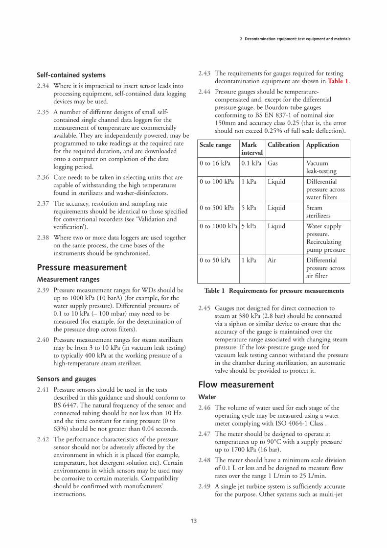
2.43 The requirements for gauges required for testingdecontamination equipment are shown in Table 1.
2.44 Pressure gauges should be temperature-compensated and, except for the differentialpressure gauge, be Bourdon-tube gaugesconforming to BS EN 837-1 of nominal size150mm and accuracy class 0.25 (that is, the errorshould not exceed 0.25% of full scale deflection).
2.45 Gauges not designed for direct connection tosteam at 380 kPa (2.8 bar) should be connectedvia a siphon or similar device to ensure that theaccuracy of the gauge is maintained over thetemperature range associated with changing steampressure. If the low-pressure gauge used forvacuum leak testing cannot withstand the pressurein the chamber during sterilization, an automaticvalve should be provided to protect it.
Flow measurement Water
2.46 The volume of water used for each stage of theoperating cycle may be measured using a watermeter complying with ISO 4064-1 Class .
2.47 The meter should be designed to operate attemperatures up to 90˚C with a supply pressureup to 1700 kPa (16 bar).
2.48 The meter should have a minimum scale divisionof 0.1 L or less and be designed to measure flowrates over the range 1 L/min to 25 L/min.
2.49 A single jet turbine system is sufficiently accuratefor the purpose. Other systems such as multi-jet
13
2 Decontamination equipment: test equipment and materials
Scale range Mark Calibration Applicationinterval
0 to 16 kPa 0.1 kPa Gas Vacuumleak-testing
0 to 100 kPa 1 kPa Liquid Differentialpressure acrosswater filters
0 to 500 kPa 5 kPa Liquid Steam sterilizers
0 to 1000 kPa 5 kPa Liquid Water supplypressure.Recirculatingpump pressure
0 to 50 kPa 1 kPa Air Differentialpressure acrossair filter
Table 1 Requirements for pressure measurements
turbine or semi-positive displacement systemscomplying with ISO 4064-1 Class B or Class Cmay also be used.
2.50 The calibration of the flow meter should beverified by comparing the indicated flow rate witha measured volume collected over a measured timeperiod. The collected volume of liquid may bedetermined by either gravimetric or volumetricmeasurement. The gravimetric method is generallymore accurate as the temperature of the liquidincreases
Chemical additives
2.51 The volume of chemical additive used for each stageof the operating cycle may be measured using a flowmeter. A number of commercially available flowsensors designed to monitor flows in the range 0 to2 L/min are suitable for interfacing to a recorder ordata logger.
2.52 The sensor should be suitable for use with fluidshaving viscosity in the range 0.8 to 20 centiStokesand should be calibrated for the viscosity of thefluid to be measured.
2.53 The sensor should be designed to operate attemperatures up to 70˚C with a supply pressure upto 1100 kPa (10 bar).
2.54 The meter/recorder should have a minimum scaledivision of 10 mL or less and be designed tomeasure flow rates over the range 50 mL/min to1500 mL/min. The system should have an accuracyof ± 2.5% of full scale or better.
2.55 The calibration of the meter should be verified bydetermining the indicated volume flowing to acollecting vessel and comparing this with thecollected volume determined by gravimetric orvolumetric measurement.
Note 1
When the meter is connected in the pipe there will bea noticeable pressure drop across the meter. Althoughthis should be less than 1 bar it may interfere with thenormal operation of the washer-disinfector andtherefore should not be used during tests for othercharacteristics than the volume of water used.
Note 2
A meter of the rotating vane type calibrated using waterat 20˚C as the flowing medium and then subsequentlyused to measure the flow of a detergent solution with aviscosity of 30 centiStokes would have an error of15–20% if no correction was applied.
Volume measurement
2.56 The volume of chemical additives and the volumeof water used in each stage are critical variables inthe control of the washing-disinfecting process.
2.57 The volume used may be measured directly bycollection in a graduated vessel of appropriate size.
2.58 Alternatively, for liquids of known density, thevolume may be determined by collection in anappropriate size vessel of known mass (empty),determination of the mass of the vessel andcontents, calculation of the mass of the liquid andhence (by dividing this volume by the density)calculating the volume of liquid.
2.59 Whichever method is used, the accuracy should besuch that the error is less than ± 2%.
2.60 Volumetric measuring containers complying withBS 5898, ISO 384 are suitable..
Other instruments Sound level meter
2.61 An integrating sound level meter is required forthe sound pressure test. It should comply withType 2 of BS EN 61672-1 and BS EN 61672-2.Ten microphones are required for the test on asingle piece of equipment.
Airflow metering device
2.62 A metering device (such as a needle valve) isrequired to admit air into the sterilizer chamberfor the air detector tests, and vacuum and pressureleak tests. The device should be capable ofcontrolling the flow of air into an evacuatedchamber. It should be adjustable and have a rangethat includes a flow of 0–5 mL/min per litrevolume of the sterilizer chamber. The error inrepeatability between 10% and 90% of the settingrange should not exceed -5%. The device isconnected to the chamber by a valved portprovided by the sterilizer manufacturer.
Balance
2.63 A laboratory balance is required for steam drynesstests, load dryness tests, calibration of flow meters(for measuring the flow of water and/or chemicaladditives) and coolant quality tests. It should becapable of measuring the mass of loads up to 4 kgto an accuracy of 0.1g and up to 400g to anaccuracy of 0.01g.
2.64 An analytical balance is required for determinationof the TDS (evaporative residue) in feed water. It
14
Welsh Health Technical Memorandum 01-01 - Decontamination of medical devices within acute services. Part B: Common elements
should be capable of measuring a mass of up to100g with an accuracy of 0.1mg.
2.65 A balance is also required for weighing thestandard textile test pack (7kg) and the metal load(15–20kg) to a 10g resolution.
Gas-monitoring equipment
2.66 A gas-monitoring instrument is required for testson equipment using chemical additives that have asignificant vapour pressure and are a potential risk.
2.67 The nature of the instrument will depend on thesubstance to be monitored. In case of doubt,advice should be sought from the manufacturer ofthe chemical additive or the AE(D).
2.68 The scale range of the measuring instrumentshould include the appropriate short-termexposure limit or occupational exposure limit andextend to at least ten times that exposure limit.
Aerosol generator
2.69 An aerosol generator is required for tests onmachines incorporating air filters intended todeliver air free from microorganisms.
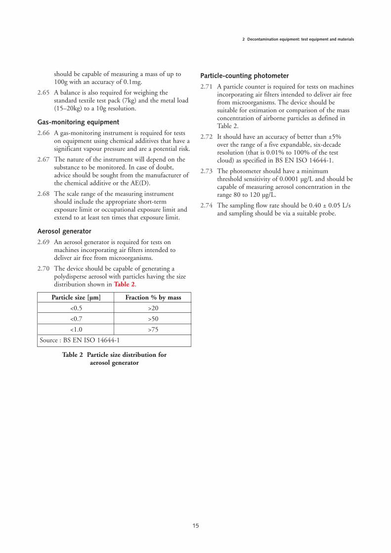
2.70 The device should be capable of generating apolydisperse aerosol with particles having the sizedistribution shown in Table 2.
Particle-counting photometer
2.71 A particle counter is required for tests on machinesincorporating air filters intended to deliver air freefrom microorganisms. The device should besuitable for estimation or comparison of the massconcentration of airborne particles as defined inTable 2.
2.72 It should have an accuracy of better than ±5%over the range of a five expandable, six-decaderesolution (that is 0.01% to 100% of the testcloud) as specified in BS EN ISO 14644-1.
2.73 The photometer should have a minimumthreshold sensitivity of 0.0001 µg/L and should becapable of measuring aerosol concentration in therange 80 to 120 µg/L.
2.74 The sampling flow rate should be 0.40 ± 0.05 L/sand sampling should be via a suitable probe.
15
2 Decontamination equipment: test equipment and materials
Particle size [µm] Fraction % by mass
<0.5 >20
<0.7 >50
<1.0 >75
Source : BS EN ISO 14644-1
Table 2 Particle size distribution foraerosol generator

3.1 This section of the guidance provides advice onthe specification, purchase and installationequipment used for the decontamination ofsurgical instruments in hospitals, laboratories andother healthcare facilities.
Technical Specification Templates have beendesigned and approved as appropriatespecifications for use within NHS Wales as part ofcontract documentation when purchasingsterilizers and washer-disinfectors. These can beobtained from the AE(D) NWSSP-FS bycontacting [email protected]. Both NWSSP-FS and NWSSP-PS should be consulted as part ofprocurement process.
Pre-purchase considerations Introduction
3.2 It is essential that the purchase of an item ofdecontamination equipment is planned correctly.This section aims to help the purchaser with astep-by-step discussion of the issues to beincluded. As this section is designed to beuniversally applicable, it might be necessary tovary the procedure according to localcircumstances or requirements.
Specialist advice
3.3 The efficient completion of procurementdocumentation will require advice and help fromNWSSP-FS, the DE(W) and AE(D) as required.
3.4 This assistance should be sought in the followingareas:
a. determining initial User requirements;
b. choosing and completing the relevant “TST”;
c. determining throughput parameters;
d. advising on relevant performance qualification(PQ);
e. post-tender analysis;
f. advising manufacturer/contractor on validationprotocols;
g. monitoring validation performance;
h. auditing validation report;
i. advising on specification qualification,installation qualification (IQ);
j. operational qualification (OQ) and PQ.
Quality systems
3.5 Adherence to engineering standards and qualitysystems ensures that decontamination equipmentis manufactured, installed, validated and subject tothe necessary periodic testing to establish theinitial and then on-going satisfactory performanceof the machine to ensure optimumdecontamination of surgical instruments and safetyof both operators and patients.
Product listing
3.6 The purchaser should list all load items proposedand projected to be re-processed by thedecontamination equipment. This should includethe following for each item:
a. number;
b. size;
c. materials of construction;
d. temperature sensitivity;
e. moisture sensitivity;
f. pressure-variation sensitivity;
g. requirements for disassembly;
h. manufacturer’s decontamination instructions;
i. usage time constraints (to determinerequirements for extra instrumentation only).
Spatial requirements
3.7 A full assessment of current space available shouldbe made. It can be that additional machinenumbers will require additional space. Thepossibilities should be considered and checkedonce a throughput calculation has been made. Themachine configuration (number of doors etc.) canaffect the spatial requirements.
16
Chapter 3 Design and pre-purchase considerations
Machine configuration
3.8 Advice on throughput calculations, equipmentnumber determination, SSD design and floorsuitable areas is given in Health Building Note 13– ‘Sterile services department’.
Protein removal and protein optimisation
3.9 All decontamination equipment should have theability to have cycle parameters varied (forexample, for washer-disinfectors – time,temperature, number of stages of main wash, useof different detergents etc.) to enable equipment tohave cycles optimised as more data becomesavailable on more effective cycles and chemicals forprotein removal (see ‘Validation and verification’).
Specification preparation
3.10 The use of the ‘TST’ will enable data provided bythe tenderer on technical points as well asfinancial data to be compared. Not only will thisenable the purchaser to confirm the acceptabilityof current services, spatial requirements andporterage, but also it will enable a like-for-liketender analysis to be made. Tender analysis will bebest achieved by formalising tender comparisonwith respect to performance and cost in all keyareas. Qualifying statements by the tenderershould be taken into account. Their effect ontender content or eligibility should be assessedbefore making a choice.
Note
The specifications allow the purchaser to define post-validation service or contract work requirements. Achoice on the relevance of these issues will need to bemade prior to distribution of the procurementdocumentation.
Procurement of equipment – anoverview Introduction
3.11 This section gives a short overview of the processof purchasing decontamination equipment. Itrefers to more detailed information in subsequentsections, including information specific to eachtype of decontamination equipment given insubsequent sections.
Purchasing decontamination equipment
3.12 The purchase of decontamination equipment canbe broken down into the following sequence ofsteps:
1. What type of load will be processed?
A knowledge of the load(s) to be processed is aprerequisite to make the correct decision aboutwhich piece of equipment to purchase; thedifficulty in obtaining a clean product, thestandard of cleanliness and the disinfectionrequired vary for different product types. Forexample, some products with intricate intersticesor long narrow lumens require specific provision ifthey are to be cleaned satisfactorily.
Purchasers should specify all items that maypresent a challenge to decontamination in order toallow the tenderer to offer the most appropriatemachine and accessories.
Manufacturers’ reprocessing instructions should betaken account of. Where instructions areparticularly onerous, these should be included asan annex in the tender document.
2. What type of machine is required?
In this guidance, washer-disinfectors are classifiedby:
• the product range which they are intended toprocess;
• their configuration and load handling type;
• the nature of the cleaning and disinfectionprocess.
Sterilizers are classified as either clinical orlaboratory sterilizers. Clinical sterilizers can useone of a number of different sterilizing agents(sterilants): purchasers should give dueconsideration to the compatibility of the items tobe processed with the process itself.
3. Where will the machine be sited?
The location available for the equipment will havea significant influence on the type of machine thatcan be used. Many of the larger continuousprocess machines require considerable space. Somemachines will require considerable building work.
4. What services are available?
Decontamination equipment will require several ofthe following services: steam, electricity, water,compressed air, drainage, effluent handling,ventilation and bulk or integral storage/supply ofchemical additives/sterilant gas supply. Themanufacturers’ data will show which services arerequired for each model. Determine which ofthese are available at the proposed site and thecapacities of each service. It might be necessary toplan for a new service, which would add greatly tothe cost of the installation.
17
3 Design and pre-purchase considerations

5. Who will operate the equipment?
Equipment located in a centralised processing unitunder the care of specially trained staff – whosesole or principal activity will be the operation ofthe machine – may be complex. Operators shouldthus be designated. Further requirements may befound in BS EN ISO 13485.
6. What capacity is required?
The likely daily and weekly workload, and thepeak hourly workload, that the equipment willhave to process should be established, then thenumber of machines required to process theworkload should be calculated. Throughput figuresfor different manufacturers’ machines and differentmodels within any given range vary considerably.For continuous process machines a distinctionshould be made between the time required toprocess one load and the total number of loadsthat can be processed in a period of one hour.Further guidance is given in Health Building Note13. Consideration should be given to the time andspatial aspects of post-process conditioning.
7. What ancillary equipment will beneeded?
A sterilizer installation might require ancillaryequipment such as special ventilation watertreatment for steam generators, air compressors,preconditioning facilities, degassing facilities andgas disposal plants.
A washer-disinfector might require ancillaryequipment such as water softeners, deionization orreverse osmosis (RO) water treatment plants, steamgenerators, air compressors, extract ventilation(with or without condensers), bulk storage anddispensing facilities for process chemicals.
A decision on treatment should be based uponinitial assessment of source water and historicalreports and cost based upon risk analysis.
In addition some machines will require loadstaging facilities, before and after processing,purpose-built load carriers for different categoriesof product, and means for returning load carriersfrom the unloading side of the machine back tothe loading side.
8. What standards or specifications arerelevant?
Most items of decontamination equipment will beconstructed to either a BS, EN or ISO Standard.In some cases additional specifications will berequired.
9. What type of contract?
Once the specification has been completed, acontract should be drawn up for the supply andinstallation of the machine.
10. Which manufacturer?
Three or more manufacturers should be invited totender for supplying the decontaminationequipment. While no manufacturer should beexcluded unnecessarily from the tendering process,they should not be invited to tender unless there isa realistic prospect of their being awarded thecontract.
11. What installation and commissioningarrangements?
After delivery and installation, thedecontamination equipment should be subjectedto a formal documented programme of validation.
12. What arrangements for service andrepair?
It is common practice for the initial purchasecontract to include all service and repair costs forthe first year after installation, that is, during thewarranty period. A number of manufacturers alsooffer an extended warranty facility that, sometimesfor an additional fee, provides an all-inclusiveservice and repair option.
13. What are the likely running costs?
Advice should be sought at the time of tender on theoperational costs of the various machines that wouldbe suitable. The operational costs should include theanticipated requirements for services (water,electricity, steam etc.), consumable items (detergents,rinse aids etc.) and maintenance. This data shouldbe used in the evaluation of the tender bids.
Choice of equipment Introduction
3.13 This section contains information relevant to thechoice of new decontamination equipment. Itdiscusses the types of machine and the loads forwhich they are suitable, and gives guidance onselecting the size and number of machinesrequired for a given application.
Choice of equipment
3.14 The choice of machine should be governed by thenature of the loads to be reprocessed. Detailedguidance on appropriate processes for differentload items can be obtained from themanufacturers of the medical devices.
18
Welsh Health Technical Memorandum 01-01 - Decontamination of medical devices within acute services. Part B: Common elements
Sizes and numbers
3.15 Precise information on the sizes and numbers ofmachines required for particular applications isdifficult to give since there are considerablevariations in patterns of use. The number ofmachines required will depend on the cycle timeand the loading capacity of the machine and insome circumstances on the flexibility of operationthat might be required, for example, whether itemsto be processed can wait until there is a full loadfor the decontamination equipment or need to beprocessed immediately.
3.16 Consideration should be given to contingencyplans for machine usage, and sufficient timeshould be included for testing, maintenance andservice. Thus, reliance on a single item ofequipment is not advisable.
Specification and contract 3.17 This section discusses general specifications for
decontamination equipment and the steps to betaken to invite tenders and issue a contract.Specific advice for sterilizers can be found inWHTM 01-01 Part C and for washer-disinfectorsin WHTM 01-01 Part D.
Preparing a specification
3.18 Purchasers should seek assistance from theNWSSP-FS and NWSSP-PS when preparing aspecification for decontamination equipment.
3.19 Standards and other specification documents arecontinually being updated, and purchasers shouldensure that they consult the latest editions of suchdocuments, including any amendments issuedafter publication, to keep abreast of changingrequirements. Advice should be sought from theNWSSP-FS (Engineering).
General design considerations
3.20 The following design considerations are applicableto all or most types of decontaminationequipment, but are not necessarily required by thecurrent Standards. Where applicable, they shouldbe included in the specification for anydecontamination equipment to be operated in thehealthcare sector.
3.21 All decontamination equipment and associatedequipment is classed as work equipment andshould comply with the Provision and Use ofWork Equipment Regulations 1998 (amended bythe Health and Safety (MiscellaneousAmendments) Regulations 2002 and the Healthand Safety (Miscellaneous Repeals, Revocationsand Amendments) Regulations 2013). Purchasers
are reminded that under the Regulations it is theresponsibility of the employer, not themanufacturer, to provide decontaminationequipment that is “suitable for the purpose forwhich it is used or provided”. (Seek latest editionof HSE regulations).
3.22 All decontamination equipment made or sold inthe UK from 1 January 1996 must conform to theemission and immunity requirements of thecurrent Electromagnetic CompatibilityRegulations 2005. This may be achieved bycompliance with BS EN 61000-6-3 (emission) andBS EN 61000-6-1 (immunity). The manufacturershould be informed of any local sources ofelectromagnetic disturbance that could affect theoperation of the machine.
3.23 For maintenance purposes, one or more panels offree-standing WDs, and side, back and top panelson sterilizers, should be easily removable andreplaceable.
Safety features
3.24 Safety features should be designed in accordancewith the British Standard code of practice forsafety of machinery, PD 5304, and the EuropeanStandards for the safety of electrical equipment,BS EN 61010-1 and BS EN 61010-2-040.
3.25 The design of the control system should ensurethat the door cannot be opened until the cycle iscomplete. When a fault is indicated the doorshould only be able to be opened by a key code ortool, when the equipment is returned to a safecondition.
3.26 Steam sterilizers should conform to therequirements listed under “Safeguards” and“Interlocking” in HSE Guidance Note PM73“Safety at autoclaves”.
3.27 The manufacturer should provide a list of all safetydevices together with their settings and methods ofadjustment.
3.28 All safety devices should be designed to fail in amanner that does not cause a safety hazard topersonnel.
3.29 Any error in the control or indication systemshould not cause a safety hazard.
Instrumentation
3.30 Where an instrument can be adjusted theadjustment should require the use of a key code ortool that is not available to the Operator.
3.31 Where a fault is indicated as an error messageshown on a visual display unit, it should be clearlydistinguishable from normal messages, for
19
3 Design and pre-purchase considerations

example, by use of a different colour or larger sizeof text. The indication should remain displayeduntil acknowledged by the Operator.
3.32 Where required within the specification, theContractor should be required to carry outadjustments to the instruments on site so that theaccuracies specified at the sterilization temperaturecan be met with the plant running and under theconditions normally prevailing on site.
3.33 There should be an indicator that shows whichstage of the operating cycle is in progress andindicates “cycle complete” at the end of the cycle.For continuous process WDs, separate indicationof the operational status should be provided foreach chamber or section.
3.34 A counter with a minimum of five digits should beprovided to indicate the cumulative total of cyclesstarted. The counter should be tamper-evident orsealed. For continuous process WDs the countershould indicate the number of loads that haveentered the machine.
3.35 For pressure or flow testing, test tees and valvecocks with sealing plugs should be fitted to permitconnection of test instruments for the verificationand calibration of all instruments permanentlyfitted to the machine. The connection should beas described in BS EN 285.
Programmable electronic systems
3.36 Modern decontamination equipment frequentlyuses programmable electronic systems (PES) forcontrol and data recording. Where such systemsare used, they should be designed in accordancewith the principles set out in the HSE document‘Programmable electronic systems in safety relatedapplications’.
3.37 Where a PES is used for control or monitoring ofthe process, the values of cycle variables critical toprocess performance and determined duringvalidation should be documented in the validationreport regardless of whether or not they are held inthe PES memory. The version number of thesoftware should be available for display whenrequired.
3.38 Combined control and instrumentation systems thatare wholly operated by means of PES shouldincorporate at least two timing systems, independentof each other, such that the timer used to control theholding time is verified by the other timer.
Doors
3.39 The choice of design for any particular installationwill depend on the workload, space restrictions,
price and ease of maintenance. With hinged doorsthere is a risk of the Operator touching the hotinside face as the door is opened. If hinged doorsare required, the specification should state whetherthey are to be hinged on the left-hand or right-hand side or top or bottom of the opening. Wheresliding doors are incorporated, the direction ofopening should be specified. The method of dooropening will impact on load handling equipmentdesign, the method of loading and unloading, theheight of the chamber above floor level, andmanual handling issues.
3.40 It should be possible to clean the contact surfacesof the door seal without removing parts of themachine.
Invitation to tender
3.41 Once detailed specifications have been drawn up,manufacturers should be invited to tender for thesupply and, if required, the installation of thedecontamination equipment.
3.42 Prospective contractors should be given thefollowing information:
1. that each machine will be subject to avalidation process as described in the validationand verification section (see ‘Validation andverification’);
2. that unless otherwise specified, the installationchecks and tests specified in the validationprocess should be satisfactorily completedbefore the machine can be accepted;
3. whether the factory/works tests (optional, onlycarried out in special circumstances), site visitsor installation checks and tests are to bewitnessed by the appropriately-qualifiedpurchaser’s representative (normally the AE(D),DE(W), AP(D) or CP(D));
4. the date by which all services will be available;
5. the date by which the validation process isexpected to be completed.
Contract
3.43 NWSSP-PS, along with NWSSP-FS, have anagreement with the NHS Supply Chain, whichhas in place a national framework agreement thatcovers sterilizers and washer-disinfectors, watertreatment systems, training, maintenance andvalidation. The framework enables procurement ofthese products and services tailored to specificreprocessing needs, without the need to instigatean OJEU tender.
3.44 Alternative forms of contract can be used dependenton Health Board/Trust policy and procedures.
20
Welsh Health Technical Memorandum 01-01 - Decontamination of medical devices within acute services. Part B: Common elements
Delivery
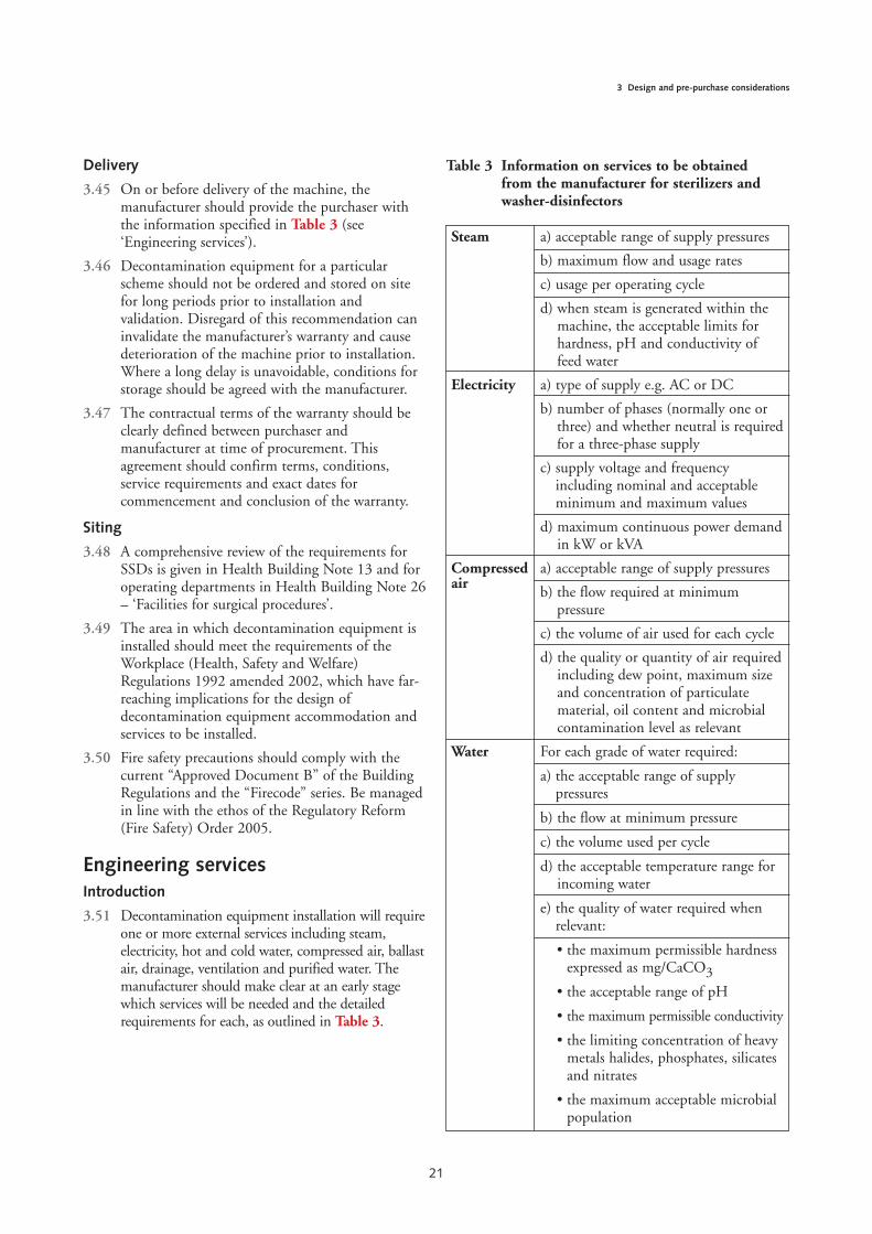
3.45 On or before delivery of the machine, themanufacturer should provide the purchaser withthe information specified in Table 3 (see‘Engineering services’).
3.46 Decontamination equipment for a particularscheme should not be ordered and stored on sitefor long periods prior to installation andvalidation. Disregard of this recommendation caninvalidate the manufacturer’s warranty and causedeterioration of the machine prior to installation.Where a long delay is unavoidable, conditions forstorage should be agreed with the manufacturer.
3.47 The contractual terms of the warranty should beclearly defined between purchaser andmanufacturer at time of procurement. Thisagreement should confirm terms, conditions,service requirements and exact dates forcommencement and conclusion of the warranty.
Siting
3.48 A comprehensive review of the requirements forSSDs is given in Health Building Note 13 and foroperating departments in Health Building Note 26– ‘Facilities for surgical procedures’.
3.49 The area in which decontamination equipment isinstalled should meet the requirements of theWorkplace (Health, Safety and Welfare)Regulations 1992 amended 2002, which have far-reaching implications for the design ofdecontamination equipment accommodation andservices to be installed.
3.50 Fire safety precautions should comply with thecurrent “Approved Document B” of the BuildingRegulations and the “Firecode” series. Be managedin line with the ethos of the Regulatory Reform(Fire Safety) Order 2005.
Engineering services Introduction
3.51 Decontamination equipment installation will requireone or more external services including steam,electricity, hot and cold water, compressed air, ballastair, drainage, ventilation and purified water. Themanufacturer should make clear at an early stagewhich services will be needed and the detailedrequirements for each, as outlined in Table 3.
21
3 Design and pre-purchase considerations
Steam a) acceptable range of supply pressures
b) maximum flow and usage rates
c) usage per operating cycle
d) when steam is generated within themachine, the acceptable limits forhardness, pH and conductivity offeed water
Electricity a) type of supply e.g. AC or DC
b) number of phases (normally one orthree) and whether neutral is requiredfor a three-phase supply
c) supply voltage and frequencyincluding nominal and acceptableminimum and maximum values
d) maximum continuous power demandin kW or kVA
Compressed a) acceptable range of supply pressuresair
b) the flow required at minimumpressure
c) the volume of air used for each cycle
d) the quality or quantity of air requiredincluding dew point, maximum sizeand concentration of particulatematerial, oil content and microbialcontamination level as relevant
Water For each grade of water required:
a) the acceptable range of supplypressures
b) the flow at minimum pressure
c) the volume used per cycle
d) the acceptable temperature range forincoming water
e) the quality of water required whenrelevant:
• the maximum permissible hardnessexpressed as mg/CaCO3
• the acceptable range of pH
• the maximum permissible conductivity
• the limiting concentration of heavymetals halides, phosphates, silicatesand nitrates
• the maximum acceptable microbialpopulation
Table 3 Information on services to be obtainedfrom the manufacturer for sterilizers andwasher-disinfectors
3.52 The specification should make it clear whereservices are to be connected. Care should be takenwhen contracts are awarded that precautionsregarding termination and availability of allengineering services are taken.
Electricity
3.53 The electrical power requirements will depend ona number of factors, such as the type of machineand the method used to heat water and hot airdryers, and generate steam. Local or integralelectrical steam generators will result in a highelectrical load. Some machines will require a three-phase supply. The manufacturer should providedetails of the type of supply (AC or DC), numberof phases, frequency, and voltages with tolerancesand loading.
3.54 Each machine should be connected via an isolator.The type of isolator will depend on the nature ofthe supply. Where a three-phase-and-neutralsupply is necessary, or where a maximum single-phase current demand is more than 13 A, themachine should be wired directly to the isolator.The switch should isolate all poles simultaneously
22
Welsh Health Technical Memorandum 01-01 - Decontamination of medical devices within acute services. Part B: Common elements
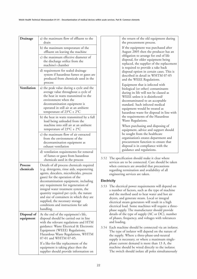
Drainage a) the maximum flow of effluent to thedrain
b) the maximum temperature of theeffluent on leaving the machine
c) the maximum effective diameter ofthe discharge orifice from themachine’s chamber
d) requirement for sealed drainagesystem if hazardous fumes or gases areproduced from chemicals used in theprocess
Ventilation a) the peak value during a cycle and theaverage value throughout a cycle ofthe heat in watts transmitted to theenvironment when the decontamination equipment isoperated in still air at an ambienttemperature of 23°C ± 2°C
b) the heat in watts transmitted by a fullload being unloaded from themachine into still air at an ambienttemperature of 23°C ± 2°C
c) the maximum flow of air extractedfrom the environment of thedecontamination equipment asexhaust ventilation
d) ventilation requirements for removalof fumes or gases from hazardouschemicals used in the process
Process Details of all process chemicals requiredchemicals (e.g. detergents, rinse aids, sequestering
agents, descalers, microbicides, processgases) for the operation of thedecontamination equipment, includingany requirement for regeneration ofintegral water treatment system, thequantity required per cycle, the natureand size of containers in which they aresupplied, the necessary storageconditions and instructions for safehandling.
Disposal of At the end of the equipment's life,equipment disposal should be carried out in line
with the relevant regulations and HTMguidance: Waste Electrical & ElectronicEquipment (WEEE) Regulations,Hazardous Waste Regulations, WHTM07-01 and WHTM 07-05.
If a like-for-like replacement of theequipment is taking place then thesupplier should provide information on
the return of the old equipment duringthe procurement process.
If the equipment was purchased afterAugust 2005 then the producer has anobligation to arrange for end of lifedisposal, for older equipment beingreplaced, the supplier of the replacementis required to provide a take backdisposal option in certain cases. This isdescribed in detail in WHTM 07-05and the WEEE Regulations.
Equipment that is infected withbiological (or other) contaminantsduring its life will not be classed asWEEE unless it is disinfected/decontaminated to an acceptablestandard. Such infected medicalequipment would be treated ashazardous waste for disposal in line withthe requirements of the HazardousWaste Regulations.
When purchasing and disposing ofequipment, advice and support shouldbe sought from the healthcareorganisation’s estates department andprocurement function to ensure thatdisposal is in compliance with theguidance and regulations.

and each pole should be fused separately. Thecable from isolator to decontamination equipmentshould be fixed and protected from the effects ofheat, water and, if applicable, steam.
3.55 Within the loading area an additional switchshould be provided so that the Operator canelectrically isolate the machine or group ofmachines in the event of an emergency. The switchshould be placed between the normal operatingposition and the exit door.
3.56 Sterilizers used to process heat-sensitive loadsshould be connected to the essential suppliescircuit, if available, to avoid heat damage in theevent of a power failure. It is not normallynecessary for washer-disinfectors to be connectedto the essential supplies circuit. Exceptions mightinclude the decision to ensure that one washer-disinfector within the SSD remains on theessential supplies circuit.
3.57 All electrical installations should conform to theInstitution of Engineering and Technology (IET)Regulations contained in BS 7671 (latest edition).Further guidance is given in Health TechnicalMemorandum 06-01 – ‘Electrical services supplyand distribution’.
Compressed air
3.58 A compressed-air supply may be required in sometypes of decontamination equipment. Where themachine does not contain an integral aircompressor, the air may be supplied from a pipedservice (mains supply) or from a local compressor.
Compressed air: mains supply
3.59 If air is supplied by pipeline from a central air-compressor system, a pressure gauge of theBourdon type complying with BS EN 837 shouldbe fitted inside the plantroom and terminated withan isolation valve.
3.60 A reducing valve or other automatic device shouldbe fitted to reduce the pressure of air delivered tothe machine to no more than the maximumsupply pressure specified by the manufacturer. Apressure relief valve will normally be required.
Compressed air: local compressors
3.61 Where it is not practicable to obtain compressedair from a mains supply, a dedicated compressed-air facility should be installed to supply machines.
3.62 At least two compressors should be provided, withauto-change between the two. The system shouldbe sized to meet all the compressed airrequirements of the unit.
3.63 The compressors are likely to be too noisy to beinstalled with the machine, and it is better to placethem in a dedicated location away from any noise-sensitive areas.
3.64 Components of the compressed air system thatrequire servicing and maintenance, such as dryersand filters, should be located where they arereadily accessible for service or exchange.
Air quality
3.65 The quality of air can be critical for someapplications, and some machines will incorporateappropriate filters. The purchaser (responsibleperson) should ensure the provision of filtered airmeets the manufacturer’s specification or therequirements given below.
1. air for controls should be free of liquid water,filtered to 25 µm (5 µm for precision controls)and lubricated with micro-fog oil particles of2 µm or less;
2. air that could come into direct contact with theload, such as air for pressure ballasting or dryingthe load, should be filtered to removecontaminating oil-mist and microorganisms. Itshould have not more than 0.5 mg of oil percubic metre of free air (measured at 1013 mbarand 20˚C; see ISO 554), be filtered to anefficiency of at least 95% when tested inaccordance with BS 3928, and be free of bacteria.
Drainage
3.66 Condensate from the jacket, heat exchangers andsteam traps is suitable for recovery and should bereturned to the steam generating plant where thereare means for recovery.
3.67 All other effluent from decontaminationequipment is potentially contaminated and shouldbe disposed of to the main drain. Effluent canoriginate from one or more of the followingsources:
1. air, condensate and steam from the chamberdrain, which might contain chemicals andmicroorganisms, especially those from a make-safe process;
2. discharge from a water-sealed vacuum pump,ejector or chamber vent, which might alsocontain microorganisms;
3. water from a chamber cooling system;
4. water introduced to cool and dilute thedischarge from the chamber;
5. effluent discharge to sewer/foul drainage.
23
3 Design and pre-purchase considerations
Ventilation
3.68 Ventilation of the area near the machines shouldbe ensured, to remove excessive heat and odours,and sterilant gases or vapours from disinfectants.
3.69 General room ventilation will be sufficient formost machines; local exhaust ventilation will berequired for chemical disinfection systems.
3.70 Electrical systems used in ventilation systemsshould take account of the high levels of humiditythat might be discharged and the potential for thisto condense within the ventilation system, as wellas the explosion risk associated with ethyleneoxide, and should comply with the requirementsof BS EN 61010-2-042.
3.71 Owing to the air leakage from clean to dirty acrosspass-through machines (based on the designpressure differential across these rooms of, forexample, 15 Pa), information on the impact ofthese machines on ventilation system designshould be sought from manufacturers.
3.72 All ventilation systems should meet the ventilationrequirements of the Workplace (Health, Safety andWelfare) Regulations 1992 (latest amendments).
3.73 Further guidance on ventilation systems can befound in Health Technical Memorandum 03-01 –‘Specialised ventilation in healthcare premises’(seek advice from NWSSP-FS EngineeringServices).
Information to be supplied by themanufacturer 3.74 For each purchase of decontamination equipment,
the tenderer is bound to supply detailedinformation on items including construction,delivery, service requirements, heat emissions andcontract performance (see the ‘TechnicalSpecification Templates’ (TST) for sterilizers andwasher-disinfectors).
24
Welsh Health Technical Memorandum 01-01 - Decontamination of medical devices within acute services. Part B: Common elements
General 4.1 This section of the guidance covers the validation
and periodic testing of the various types ofdecontamination equipment used in hospitals,laboratories and other healthcare facilities.
Permit-to-work 4.2 The use of permit-to-work system should be
practiced for all maintenance and testing procedureson decontamination equipment. This should ensurethe formal removal of equipment from, and returnto, service and will provide certification ofacceptance by the User.
4.3 This topic is covered in Chapter 6 of WHTM 01-01 Part A and includes an example of a Permit-to-Work form. Each organisation should constructtheir own template based upon local requirementsand policies. Signatories will be based upon localmanagement structure.
Testing of decontaminationequipment 4.4 Good decontamination practice is based on four
key aspects that ensure that the required standardsof performance and safety are met and sustained:
1. all decontamination equipment is subjected to aprogramme of validation;
2. all decontamination equipment is subjected to aplanned programme of periodic testsperformance;
3. all decontamination equipment is operated bytrained staff in its use in accordance with awritten procedure including manufacturers’instructions and local procedures;
4. all decontamination equipment is subjected to aprogramme of planned preventativemaintenance irrespective of whether apreventative maintenance scheme is operated onthe premises.
4.5 Expertise on all aspects of the operation andtesting of decontamination equipment is availablefrom several sources, including the AE(D),
DE(W), AP(D), CP(D), User and manufacturer.
4.6 Schedules of tests for washer-disinfectors andsterilizers are included in WHTM 01-01 Parts Cand D. Most tests are defined in the relevantBritish, European or International Standard. Thesedocuments should be used as the prime referencefor such testing. Where there is no currentStandard, testing protocols are defined within thisguidance. Future publication of new Standards, orrevisions of existing Standards, will render some ofthe content of this guidance no longer applicable.Advice should be sought from the AE(D) orDE(W) regarding the state of any relevantStandard and the current relevance of testingprotocols defined within this WHTM.
4.7 Maintenance of all decontamination equipment isdealt with in WHTM 01-01 Parts C and D.
Responsibilities General
4.8 Decontamination equipment should be subjectedto a planned programme of testing both beforedelivery and on-site. The on-site testing should becarried out using the procedures described in thisguidance and should include installationqualification, operational qualification and processqualification. The purchaser, manufacturer,contractor AE(D), DE(W) AP(D) and CP(D)have distinct responsibilities.
4.9 The AE(D)/DE(W) should review the results ofpre-delivery works tests carried out by themanufacturer, and review the test instrumentsprovided by the contractor and/or the CP(D) toensure that their accuracy, calibration andcondition meet the standards for test instrumentsdescribed in ‘Validation and verification’. TheAE(D)/DE(W) should witness such installation,operational and performance qualification testingas appropriate to verify that the requirements ofthe specification are met and that the equipment isfit for purpose. New equipment should only bebrought into use after written confirmation fromthe AE(D)/DE(W).
25
Chapter 4 Validation and verification
4.10 The AE(D)/DE(W) or Responsible Engineershould witness the installation checks and testscarried out by the contractor, including ensuringthat the calibration of each test instrumentprovided by the contractor has been checked onsite and is satisfactory, and should arrange for testloads to be supplied as required. This Engineershould carry out the installation qualification tests,operational qualification and performancequalification.
Responsible Persons
4.11 The decontamination process requires theinvolvement of the following Responsible Persons:
a. Authorising Engineer (Decontamination)(AE(D))
b. Decontamination Engineer (Wales) (DE(W))
c. Authorised Person (Decontamination) (AP(D))
d. Competent Person (Decontamination) (CP(D))
e. Manufacturer/Equipment Supplier
f. Contractor
g. Purchaser
h. Consultant Microbiologist
i. Infection Control Officer
j. User
k. Decontamination Management
l. Responsible Engineer – Appropriately trainedofficer undertaking testing, validation service orwitnessing part of process on behalf ofhealthcare organisation. May be an AP(D),CP(D), DE(W) or other nominated officerworking in communication with NWSSP-FS.
Works tests4.12 Works tests before delivery of the decontamination
equipment are intended to verify that theequipment performs in conformity with the resultsobtained from type testing in respect of variouscritical attributes. (See BS EN 15883-1 and 15883-2 for works test details for washer-disinfectors andBS EN 285 for works test details for sterilizers.)
4.13 For one-off designs, a more extensive programmeof works tests, similar to the programme of typetests for machines in serial production, is required,and the purchaser might wish to arrange for theirrepresentative (either the AE(D) or CP(D)) toattend the factory to witness these tests beforeaccepting delivery of the decontaminationequipment.
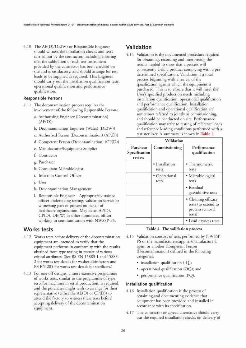
Validation4.14 Validation is the documented procedure required
for obtaining, recording and interpreting theresults needed to show that a process willconsistently yield a product complying with a pre-determined specification. Validation is a totalprocess beginning with a review of thespecification against which the equipment ispurchased. This is to ensure that it will meet theUser’s specified production needs includinginstallation qualification, operational qualificationand performance qualification. Installationqualification and operational qualification aresometimes referred to jointly as commissioning,and should be conducted on site. Performancequalification may refer to testing of reference loadsand reference loading conditions performed with atest sterilizer. A summary is shown in Table 4.
4.15 Validation consists of tests performed by NWSSP-FS or the manufacturer/supplier/manufacturer’sagent or another Competent Person(Decontamination) defined in the followingcategories:
• installation qualification (IQ);
• operational qualification (OQ); and
• performance qualification (PQ).
Installation qualification
4.16 Installation qualification is the process ofobtaining and documenting evidence thatequipment has been provided and installed inaccordance with its specification.
4.17 The contractor or agreed alternative should carryout the required installation checks on delivery of
26
Welsh Health Technical Memorandum 01-01 - Decontamination of medical devices within acute services. Part B: Common elements
Validation
Purchase Commissioning PerformanceSpecification qualification
review
• Installation • Thermometrictests tests
• Operational • Microbiologicaltests tests
• Residualgas/additive tests
• Cleaning efficacytests (to extend toprotein removaltests)
• Load dryness tests
Table 4 The validation process
the decontamination equipment, to ensure thatthe machine has been supplied and installedcorrectly, is safe to operate, has been provided withsatisfactory services that do not impair theperformance of the machine, and that in operationthe machine does not interfere with otherequipment.
4.18 Ancillary equipment such as service supplies andventilation systems should be checked by thecontractor responsible for their installation.
4.19 When these checks have been completed andfound satisfactory, the contractor should carry outthe installation tests necessary to demonstrate thatthe decontamination equipment is workingsatisfactorily. The contractor is not required tocarry out any thermometric tests unless these werespecified in the purchase contract. Any assistancerequired from the purchaser should be agreed aspart of the purchase contract.
4.20 If any modification, maintenance or repair work iscarried out on the steam, water, compressed airventilation, piped gas services or drainage systemsafter the installation tests have been completed,the relevant installation tests should be repeated bythe CP(D) before the operational tests areundertaken.
4.21 The schedule for installation checks and tests is setout in WHTM 01-01 Parts C and D.
Operational qualification
4.22 Operational qualification is the process ofobtaining and documenting evidence that installedequipment operates within predetermined limitswhen used in accordance with its operationalprocedures.
4.23 When the decontamination equipment has beeninstalled and accepted by NWSSP-FS orResponsible Engineer should carry out a sequenceof operational performance tests to evaluate thebasic performance and safety of thedecontamination equipment. Some of these testsare identical to those specified as installation tests,and need not be repeated if operational testingfollows within ten working days of the completionof the installation tests.
4.24 The schedule for operational tests is set out inWHTM 01-01 Parts C and D.
Performance qualification (PQ)
4.25 PQ is defined as the process of obtaining anddocumenting evidence that the equipment, asinstalled and operated in accordance with
operational procedures, consistently performs inaccordance with predetermined criteria andthereby yields product meeting its specification.
4.26 PQ consists of tests designed to show that:
1. for washer-disinfectors, soil removal andcleaning have been effective throughout theload and the washer-disinfector chamber, andthe products are of the required standard ofcleanliness, free from process residues (whenapplicable). Again, the use of a test thatenables quantitative analysis of protein removalis to be used when appropriate technologiesbecome available. These tests will beconducted on sample instruments derivedfrom the normal decontamination stream. Theuse of test soils for specifically for this purposeis not envisaged;
2. decontamination conditions have been attainedthroughout the load and the machine’schamber, and to the required standard for thetype of load being processed. A thermometrictest is sufficient for most items ofdecontamination equipment. Additionalmicrobiological tests will be required forwasher-disinfectors that use chemicaldisinfectants.
4.27 In principle, it might be argued that a PQ test isrequired for each loading condition that an item ofdecontamination equipment is required to process.In practice, it is possible to identify reference loadsand reference loading conditions that present anequal or greater challenge to the process than theloads that might be encountered in normal use.New load items should not be processed until oneof the following is the case (Advice to be obtainedfrom NWSSP-FS):
1. PQ tests, as specified in the appropriatevalidation and verification section, have beenconducted by the CP(D) to the satisfaction ofthe User and the AE(D)/DE(W);
2. the User is satisfied that the new load item isrepresented by one of the existing loadingconditions/process cycles for which a PQ reportexists;
3. the instructions from the manufacturer of theitem are sufficiently detailed and specific thatthe appropriateness of the proposed treatment isreadily apparent.
4.28 The User, in consultation with themanufacturer(s) of the load items, theAE(D)/DE(W) and the control of infection officeras necessary, should ensure that the load is suitable
27
4 Validation and verification
for the process to which it is to be exposed. Thisshould include consideration of the compatibilityof all process chemicals used.
4.29 The process selected will depend on the nature ofthe load and its ability to withstand theenvironmental conditions present during theoperating cycle. The rates of change of cyclevariables, such as temperature and pressure, mightalso need to be considered.
4.30 Before selecting a process it might be necessary tocarry out preliminary tests on the product, or on asurrogate product, to determine both the levels andrates of change of the cycle variables necessary toachieve the required result, and to determine whichcan be tolerated by the product without causingunacceptable changes in its performance. Otherwise,manufacturers’ instructions may be used.
Loading4.31 The User should ensure that each load is presented
to the process in accordance with documentedprocedures established and tested during PQ.
4.32 Baskets or load carriers should be appropriate forpurpose, not be overloaded, as this will result ininefficient cleaning and disinfection. (Digitalrecords could be retained as evidence of validatedloading patterns)
4.33 Cannulated load items, which are intended to beconnected to spigots on the load carrier to ensureflushing of the lumen, should be properlyconnected, as otherwise they will not beadequately cleaned and disinfected.
4.34 Small and light items should be secured with ahold-down screen or by other means; if they arefree to move around there is a serious risk ofdamage to the instruments. Small, sharpinstruments that have moved within the loadcould also represent a hazard to staff who have tosubsequently handle the load.
4.35 Load carriers should only be used with the itemsfor which they were intended.
Documentation4.36 Accurate and efficient record-keeping is an
essential part of the management ofdecontamination equipment. The extent andnature of the records that are necessary varies withthe type of machine and the use to which it isput. Guidance is given in WHTM 01-01 Parts Cand D.
Summary sheets
4.37 On completion of the validation process, andbefore leaving the premises, the Test engineer orCP(D) should prepare a summary reportcontaining the results of the commissioning andPQ tests and essential working data.
4.38 At the request of the User the CP(D) should alsosupply graphical representations of cycle variablesobtained from the thermometric tests.
4.39 The summary report should be signed by theCP(D) and countersigned by the AP(D) to certifythat the machine is fit for use.
4.40 Summary reports should be securely retained bythe User and be available for ready reference.
4.41 At the same time the CP(D) should provide theUser with copies of any master process recordsrequired for routine production.
Validation report
4.42 Within six weeks of the completion of thevalidation process the Responsible Engineer shouldprepare a full validation report which shouldinclude:
1. all the data supplied by the contractor, collectedduring the installation checks and tests withwritten confirmation that they meet themanufacturer’s specification;
2. written confirmation that the calibration of allmeasuring instruments fitted to the machinehave been verified;
3. all the data collected during the commissioningtests, with written confirmation from theCP(D) that they meet the specifiedrequirements;
4. data showing the correlation between theperformance of the measuring instrumentsfitted to the machine and the test instrumentsused during commissioning and PQ;
5. reports containing all the data collected duringthe PQ tests, with written confirmation fromthe CP(D) and the User of the loadingconditions and types of load (including, whennecessary, reference to specific individual items,digital records) that may be satisfactorilyprocessed in the machine;
6. data from the instruments fitted to themachine, independent monitoring system dataand validation instrument data, along withcomments on any changes or adjustments made
4.43 When data is in the form of electronic data files,the report should include copies of disks/DVD or
28
Welsh Health Technical Memorandum 01-01 - Decontamination of medical devices within acute services. Part B: Common elements
CD or tapes containing the data in a formatcompatible with local systems and policies and aprintout of the directory of each, annotated toshow where the data for each test is to be found.
Note
The User is responsible for ensuring that one hard copyis retained with evidence of responsible signatories aspart of a controlled document in accordance with localquality management system.
4.44 The CP(D) should certify that all necessary testshave been carried out and that the results weresatisfactory.
4.45 The records of any microbiological tests should besigned by the Microbiologist.
4.46 The Responsible Engineer should forward thecompleted validation report to the AE(D)/DE(W)for audit. The AE(D)/DE(W) should issue areport of findings to the User and otherResponsible Officers within the organisation,Estates/Microbiologist as example.
4.47 The validation report should be retained by theUser. Copies may be retained as necessary by theCP(D), the AE(D), the Microbiologist and, whereapplicable, the Quality Controller.
Periodic tests4.48 After validation and when the machine is passed
into service, it should be subject to a schedule ofperiodic tests at daily, weekly, quarterly and yearlyintervals, to provide evidence that the machinecontinues to operate within the limits establishedduring commissioning.
4.49 The User and the CP(D) (under the managementof the AP(D)) are responsible for the periodictests.
4.50 The yearly test schedule is a revalidation procedureand provides a more comprehensive testprogramme than the other periodic tests; it servesto demonstrate that data collected duringcommissioning and the PQ remain valid.
Revalidation4.51 In addition to annual revalidation, revalidation is
required under the following circumstances:
1. when the machine is to be returned to serviceafter repair or component replacement of partof the systems that affect satisfactory attainmentof the pre-set variables of the operating cycle;
2. when the pre-set values of the cycle variableshave been modified;
3. when the software in a programmable electronicsystem (PES), used for control of the process,has been modified;
4. whenever the User or NWSSP-FS advises thatrevalidation is necessary:
a. when the pattern of a batch process record isoutside the limits specified on the masterprocess record;
b. when the equipment fails a periodic test;
5. whenever it is required by an authorisedinspectorate or licensing authority.
4.52 The full revalidation procedure is identical to thatspecified for the yearly test.
4.53 It will not always be necessary to carry out a fullrevalidation, and the advice of NWSSP-FS shouldbe sought on which tests are required followingany particular event.
Repeat validation4.54 Revalidation and periodic tests are designed to
establish the continued conformance of theequipment and its performance with dataestablished during the original validation study.
4.55 There are occasions when it might be necessary torepeat the full set of tests carried out during theinitial validation in order to obtain a new set ofdata.
4.56 Repeat validation should be carried out if:
1. the machine is modified to such an extent thatit must be presumed that the original data isno longer valid;
2. a machine has been moved and installed at anew site;
3. the machine has been dismantled orextensively overhauled;
4. a new operating cycle has been introduced;
5. the User or NWSSP-FS advises that repeatvalidation is necessary;
6. it is required by an authorised inspectorate orlicensing authority;
7. revalidation fails to confirm compliance withthe original data and no cause for thediscrepancy can be found;
8. there have been time and temperatureadjustments or parameter changes;
9. there has been a change in process chemicalsused;
10. a new packaging system has been introducedthat may require alteration of the
29
4 Validation and verification

configuration to ensure attainment of processrequirements.
4.57 It will not always be necessary to carry out a fullrepeat validation, and the advice of the NWSSP-FS should be sought as to which tests are requiredfollowing any particular event.
Types of test 4.58 The tests listed in the schedules fall into the
following categories:
1. Automatic control tests, which are designed toverify the correct functioning of the operatingcycle from the readings obtained from theinstruments fitted to the machinee;
2. Thermometric tests, which are designed toprovide assurance that the temperaturerequirements for the process are met by usingaccurate measuring equipment, independent ofthe instruments fitted to the machine tomonitor the temperatures attained within thechamber and reference loads;
3. Thermometric tests for a small load, which aredesigned for two purposes. In sterilizers with anactive air removal system they demonstratethat the sterilizer is capable of removing airfrom a small load in which air from a near-empty chamber has been retained.Thermometric tests for a full load are designedto show that services provided to the machineare adequate for purpose. In certaincircumstances they may also serve as PQ testsfor loading conditions that present a lesserchallenge to the operating cycle than thespecified full loads;
4. Microbiological tests, which are designed toshow that disinfection (sterilization) conditionsare attained when thermometric methods aloneare inadequate for this purpose;
5. Cleaning efficacy tests, which are designed toshow, by monitoring the removal of a test soil,that the process will effectively clean products ofthe type to be processed.
4.59 Other tests, specific to certain types of sterilizer,are designed to show that the steam supply issuitable, the sterilizer does not produce too muchnoise, the chamber is airtight, gaseous sterilants arenot released into the environment, and safetydevices are functioning correctly.
4.60 Other performance tests specific to certain types ofmachine are designed to provide assurance that themachine will perform correctly under theanticipated conditions of use.
Procedure on failure of a test 4.61 There should be no difficulty in ensuring that a
correctly installed and maintained piece ofdecontamination equipment will comply withboth the validation tests and periodic testsdescribed.
4.62 Failure of a test generally indicates that a machineis not working to specification; it should bewithdrawn from service and the failureinvestigated.
4.63 In practice, the action to be taken is a matter ofjudgement and will depend on the nature of thefailure and the use to which the machine is beingput. It might be acceptable for the equipment tocontinue operating under carefully definedrestrictions until the cause of the failure can beestablished and rectified.
4.64 NWSSP-FS, the AP(D) and the User should agreethe course of action to be taken.
4.65 The User has the ultimate responsibility forcertifying that decontamination equipment is fitfor use.
Principles of installation andoperational tests 4.66 On delivery of decontamination equipment, the
manufacturer/contractor should carry out theinstallation checks included in the contract and asset out in this chapter to establish that:
1. the equipment has been provided and installedcorrectly;
2. the equipment is safe to operate;
3. the equipment does not interfere with otherequipment;
4. all connected services are satisfactory and do notprevent attainment of the designed cleaning anddisinfection/sterilization performance of theequipment.
4.67 The contractor responsible for installing theequipment should carry out installation checks onservices and other ancillary equipment. Thesechecks should be completed and all services andancillary equipment found to be satisfactory beforecarrying out installation checks on the equipmentitself.
4.68 The contractor responsible for installing thedecontamination equipment should carry out anyadditional checks specified by the manufacturer.
4.69 The CP(D) should carry out any checks specifiedin this chapter that were not included in the
30
Welsh Health Technical Memorandum 01-01 - Decontamination of medical devices within acute services. Part B: Common elements

purchase contract for the decontaminationequipment.
4.70 Installation tests are defined in WHTM 01-01Parts C and D.
4.71 Operational tests are performed in standardspecified manner using defined reference loads.Details of operational tests are defined in WHTM01-01 Parts C and D.
Principles of performancequalification tests4.72 Performance qualification (PQ) is defined as the
process of obtaining and documenting evidencethat the equipment, as installed and operated inaccordance with operational procedures,consistently performs in accordance withpredetermined criteria and thereby yields productsmeeting its specification.
4.73 PQ tests should be performed as part of the initialvalidation procedure, as part of any repeatvalidation procedure and whenever the User,acting on the advice of NWSSP-FS, judges thatnew loading or operating conditions require a newPQ test.
4.74 Circumstances that might lead to new PQ testswould include changes to the quality of the watersupply, changes to the chemical additives used inthe cleaning and disinfection process, changes tothe loading system or the requirement to process anew type of product or packing arrangements fordecontamination equipment.
4.75 PQ should not be undertaken on any piece ofequipment until the requirements of theinstallation and operational tests specified inWHTM 01-01 Parts C and D have been met.
4.76 Soil removal efficacy tests should be carried out onall washer-disinfectors as part of the PQ (seeWHTM 01-01 Part D).
4.77 Thermometric PQ may not be required for allloads. Consideration should be given to tests foreffective sterilization and drying of metal loads,and of any particular loads agreed between theUser and the NWSSP-FS.
4.78 PQ tests should be carried out by the CP(D).
4.79 Each test should be cross-referenced to a detaileddescription of the test procedure. Unless otherwisespecified, the tests should be carried out with thedecontamination equipment at normal workingtemperature, which might require a “warm-up” runto be carried out before commencement of the tests.
4.80 Test data obtained from the PQ tests should berecorded in a written PQ report that clearlyidentifies the loading conditions, the operatingcycles, any chemical additives, and the water andsteam quality used at each stage of the cycle.
4.81 The User should employ the PQ report to confirmthe suitability of the process for loads that are tobe processed. It should be used by the CP(D) andAE(D) as the basis for comparison withsubsequent performance requalification tests.
4.82 Performance requalification (PRQ) is the processof confirming that the equipment continues tomeet the performance standards established duringPQ and that the working data established duringPQ tests remain valid.
4.83 PRQ is carried out annually as part of the yearlytest schedule, as part of any revalidation or repeatvalidation study, or whenever the User requestssuch confirmation.
4.84 Before undertaking PRQ tests the CP(D) shouldconfirm, either by testing or by reference tocurrent test records, that the machine meets therequirements of the installation and operationaltests.
Loading conditions
4.85 A loading condition is a specified combination ofthe nature and number of load items, the items ofchamber furniture, and their distribution withinthe chamber. For example, a load placed on thetop-most level of a four-level load carrierconstitutes a different loading condition from thesame load placed on the lowest level.
4.86 In principle, validation is not complete until a PQtest has been performed for each loading conditionthat the equipment is expected to process. Inpractice, the loading conditions specified in the teststo be carried out during commissioning aredesigned to represent the majority of productionloads and to present a greater challenge to theprocess than production loads. In these cases furtherPQ tests will not be required; the data obtainedfrom the commissioning tests will be sufficient.
4.87 PQ tests are required under the followingconditions:
1. when the proposed production loadingcondition presents a greater challenge to theprocess than that presented by thecommissioning tests; for example, washer-disinfectors for surgical instruments will requirePQ tests if the mass of metal instruments to beprocessed exceeds that of the standard test load
31
4 Validation and verification
or if it is intended to process instruments withnarrow lumens. Also, while porous loadsterilizers rarely need PQ tests, such tests will berequired if the density of the porous materialexceeds that of the standard test pack (see‘Testing: additional information’ in WHTMPart C) or if narrow lumens restrict air removaland steam penetration;
2. when the nature of the load is not representedby the commissioning tests; for example, certainloads might be damaged by exposure to thenormal cycle temperature. In these cases, thesettings of cycle variables and their permittedtolerances should ensure not only that the loadis correctly processed, but also that it is notunacceptably degraded by long exposure to hightemperatures.
4.88 When PQ tests are required, it is often possible toselect a production load that is known to be agreater challenge to the process than any of theothers. This reference load can then serve as a“worst case” and allow one PQ test to be valid fora range of less demanding conditions. Forsterilizers, reference should be made to BS EN17665 prior to commencing this process.
4.89 A microbiological PQ test may be required fordetermining air removal and steam penetrationinto complex devices where thermometric methodsmay prove inadequate. The advice of the NWSSP-FS should be sought in such cases.
4.90 The responsibility for deciding which loadingconditions require PQ tests should be consideredby the User, CP(D) and NWSSP-FS. The AP(D)should be made aware of the decisions made.
PQ report
4.91 All the data collected during PQ tests should befiled in a PQ report, a copy of which should bekept with the plant history file.
4.92 The PQ report should contain or refer to thecomplete specification for the decontaminationprocess. The specification should be sufficientlydetailed to allow the loading condition and theoperating cycle (including the type and volume ofall chemical additives and the water quality) to bereplicated on any future occasion.
The report should include the following:
1. a specification of the loading condition definedby the nature and number of the load items,items of chamber furniture and theirdistribution within the chamber. Photographstaken of the load are valuable for futurereference and can minimise the need for
extensive descriptive text;
2. a specification of the operating cycle, defined bythe settings for the cycle variables. Formicroprocessor-based control systems a copy ofthe program held independently on electro-magnetic storage media is suitable also;
3. a specification of the service supply, defined byreference to the nature and volume of allchemical additives and the quality of the waterservice(s);
4. a specification of any preconditioning,conditioning and degassing process;
5. a specification of any pre-test operation of thedecontamination equipment, for example awarm-up cycle;
6. a specification of any pre-treatment of the testload, for example, manual cleaning, ultrasoniccleaning etc.;
7. all the indicated, recorded and measured datafrom the test. These should be annotated withthe target values and permitted tolerances ofelapsed time and other cycle variables at allsignificant points of the operating cycle, forexample, at the beginning and end of each stageor sub-stage;
8. for loads which require the removal of air beforesterilization, the method used to verify whetherthe minimum conditions of steam penetrationinto the load are attained (for porous loadsterilizers, this is by use of the air detector);
9. for machines equipped with process recording,the original of the process record derived fromthe test should also form part of the record.
4.93 Immediately following the PQ tests, the CP(D)should prepare PQ summary sheets and workingcopies of any necessary master process records.These should be given to the User and kept withthe sterilizer process log.
4.94 If PQ tests are not required, the PQ summarysheet should contain data from the thermometrictest for a full load and be marked accordingly.
Understanding of condensate controlin a porous load sterilizer
4.95 In porous load steam sterilizers, the energy thatheats the load is derived almost entirely from thelatent heat given up as the steam condenses on theload items. The more latent heat is given up, themore condensate will be formed, and it is thecondesate controlled at the mean temperature andpressure of 136oC that actually carries out thesterilization process. This condensate (hot water) is
32
Welsh Health Technical Memorandum 01-01 - Decontamination of medical devices within acute services. Part B: Common elements
essential for the process and is an unavoidableconsequence of steam sterilization.
4.96 The microbicidal effectiveness of a sterilizationprocess can only be determined by a validationprocess appropriate to the packaging and loadunder test. The removal of air, rate of change ofpressure, temperature distribution within theproduct and measured exposure times will need tobe configured for each method of packaging andcontainment. The traditional standard cycle maynot be appropriate for the sterilization of certainload configurations.
4.97 The amount of condensate formed will depend onthe latent heat required to raise the load to thesterilization temperature [pressure]. This dependson the heat capacity of the load, which in turndepends on the mass and specific heat capacity ofeach item placed within the chamber, includingwrapping and the carriage. Loads containing metalitems have a higher heat capacity than a load ofpurely porous materials and therefore will producemore condensate.
4.98 The process is substantially reversible, however, andby subjecting the chamber to a vacuum during thedrying stage, the lowered boiling point of waterassociated with the reduced pressure enables the heatenergy stored within each load item and carriage, tore-evaporate the condensate and, as a consequence,the item is both cooled and dried. The re-evaporation process will not occur if the condensatebecomes separated from the load items to which thelatent heat was given, or from the load itemsaltogether. This term is often referred as “migration”.This then can lead to wet items that have had excesscondensate placed onto them than the thermalcapacity can deal with within the process.
4.99 In order to ensure that porous loads have reachedthe levels of dryness illustrated in BS EN ISO 285,it is necessary either to drain the condensatecompletely clear of the load, or to retain it close tothe hot load items where it can be evaporated. Withwrapped loads, the latter solution is preferred.
4.100 Special measures will probably not be needed forpurely porous loads, but metal items are likely toproduce sufficient condensate to saturate theirwrapping. The condensate can then spread toother parts of the load from which it cannot beevaporated. This migration of condensate can beavoided by including absorbent padding (inaddition to the wrapping) suitably positionedinside each pack.
4.101 Holloware, such as bowls and tubes, should bearranged in such a way to reduce the potential for
condensate to collect inside them. It might not bepractical to ensure that wrapped holloware is alwaysprocessed inverted and in this case the drainageproblem can be overcome by strategically placingappropriate absorbent materials inside the items.
4.102 If a mixed load of porous and wrapped metalitems is to be processed, the porous items shouldbe placed above the metal items to ensure thatcondensate does not drip on to them.
4.103 New standards and procedures are being used tocomply with the latest EN standards, and theseinclude the removal of porous materials from setsand trays, and the more common use of waterrepellent wrapping materials. This will createproblems of moisture retention if not monitoredand checked on a regular basis and checks by SSDmanagement in conjunction with the AE(D) orResponsible Engineer.
The use of metal containers within thedecontamination process
4.104 The use of metal containers is becoming morewidely spread in the NHS, especially in loan setsand orthopaedic instrumentation. Healthorganisations contemplating the use of metalcontainers should consider the points listed in4.106 if they are to be used without anappropriate validated procedure to determine thatcycle configuration is appropriate to direct loadingconditions.
4.105 If metal containers are used within a department,such use must be planned carefully as thecontainers need to be cleaned and washed to thesame standard as the instruments they contain.This will require an increase in washer disinfectorcapacity for the department (usually resulting in a40% increase in chamber or machine capacity).
4.106 When contemplating the use of metal containers,the following points should be considered:
1. the likely increase in washer disinfector capacity;
2. the handling and weight increases in alignmentwith local manual handling policy - riskanalysis;
3. the need to request sterility test results orcontrol methods from manufacturer;
4. the recommended periods of seal replacement inalignment with manufacturers’recommendations;
5. the recommended period of filter replacementand housing details;
6. the need to carry out tests to check for anydeformities of container bases or lids (jigs);
33
4 Validation and verification
7. the need for identification of seal container –tag type system;
8. the need to wrap containers in order to includea dust layer or comply with theatre handlingpolicies.
4.107 Experience in Wales has shown that, at the time ofwriting this guidance, there was no method forensuring that the filter[s] were secure in thefixings, or the seals in the lids were workingcorrectly. Therefore, if utilized, PQ tests should becarried out and each container/box wrapped toensure against handling issues and against thepossibility of filter failure.
4.108 Prior to introducing such systems, healthcareorganisations must undertake a documented riskassessment in accordance with BS EN ISO 14971.
Loading carriages
4.109 The inclusion of drip deflectors between tiers ofinstrument trays can assist in preventingcondensate dripping from one shelf to another.However, the design of the deflectors is critical inorder to consistently achieve the requiredconditions on cycle conclusion. Aluminiumdeflectors are usually more effective than stainlesssteel.
4.110 Shelving is more effective as an open mesh designrather than solid type sheet.
4.111 Any changes to wrapping materials and chambercarriages should only be carried out afterundergoing a validated process. The User shouldconsult with the AE(D) or DE(W) at NWSSP-FSprior to introducing such changes. Any suchchanges can potentially reduce the effectiveness ofair removal, prevent sterilization at all points ofthe load and result in the release of a load thatthat has not been sterilized to the requiredstandard.
Product release4.112 The User, in consultation with the NWSSP-FS,
should establish and document procedures toensure that loads are not released for use until theUser is satisfied that the product has beenprocessed within permitted equipment cycleparameters established duringvalidation/performance qualification, for eachstage of the decontamination process.
4.113 Product release procedures should confirm, forexample:
• that the process equipment loading arrangementis consistent with that used duringvalidation/PQ testing;
• that the products have been packaged andassembled in accordance with the PQspecification, and that the process has not resultedin any damage or deterioration of packaging;
• that the operating cycle for process equipment isin accordance with the PQ specification;
• that the process equipment batch process recordmeets PQ specification for all cycle variables.
4.114 Confirmation that the process equipment batchprocess record meets PQ specification for all cyclevariables may be achieved automatically via anindependent process variable monitoring system(IMS) which compares cycle process control dataand independent process variable monitoring dataand confirms cycle performance within validatedcycle parameters; or by manually comparing thebatch process record (BPR) with a master processrecord (MPR) of the validated PQ test, and notingthe outcome on the BPR together with theoperator’s signature and reference number of theMPR used.
4.115 The performance and requirements ofindependent process variable monitoring systemsare detailed in the ‘Technical SpecificationTemplates’ for sterilizers and washer-disinfectorsavailable from the Authorising Engineer(Decontamination) [email protected] or NWSSP-PS.
4.116 A master process record may take the form of atransparent copy of the batch process record forthe equipment validated PQ test, with variablelimits specified and the MPR suitably referenced;or other convenient system which allows theoperator to confirm that the production cycleparameters are within those established during thevalidated PQ test. Differing process cycles willrequire different MPRs.
Tests for performance requalification(PRQ) 4.117 PRQ tests should be performed once a year to
ensure that the established criteria fordecontamination are still being met. The PRQtests should follow the yearly schedule of tests andchecks listed in the specific sections for sterilizersand washer-disinfectors.
4.118 For a given operating cycle the PRQ tests shouldonly be carried out for those reference loads forwhich a PQ test was performed and reported.
4.119 The need for additional PQ tests in the light ofchanges in the nature of loads being processedshould be agreed between the User and the CP(D).
34
Welsh Health Technical Memorandum 01-01 - Decontamination of medical devices within acute services. Part B: Common elements
4.120 The procedure for the PRQ test is essentially thesame as that used for the corresponding PQ test.The operating cycle and the loading conditionsused should be identical with those usedpreviously for the PQ test.
4.121 The PRQ test should be considered satisfactory ifthe values of the measured variables are within thetolerances stated in the PQ report.
4.122 The results of the PRQ tests should be linked withthe relevant PQ report and retained securely.
4.123 The PRQ test should meet the specifiedrequirements without difficulty fordecontamination equipment that has passed theyearly test programme. If the PRQ test is notsatisfactory the advice of the NWSSP-FS and/orthe manufacturer should be sought.
4.124 Full details of PRQ tests can be found in WHTM01-01 Parts C and D.
35
4 Validation and verification

British Standardshttp://shop.bsigroup.com/
� BS 6447 - Specification for absolute and gaugepressure transmitters with electrical outputs
� BS 5898 S 5898:1980, ISO 384:1978 - Specificationfor principles of design and construction ofvolumetric glassware for laboratory use
� BS 7671- Requirements for electrical installations.IET Wiring Regulations.
� BS EN 285- Sterilization. Steam sterilizers. Largesterilizers
� BS EN 837-1- Pressure gauges. Bourdon tubepressure gauges. Dimensions, metrology, requirementsand testing (see also clause 3.59)
� BS EN 60584-2- Thermocouples. Tolerances
� BS EN 60751 - Industrial platinum resistancethermometers and platinum temperature sensors
� BS EN 61000-6-1 - Electromagnetic compatibility(EMC). Generic standards. Immunity for residential,commercial and light-industrial environments
� BS EN 61000-6-3 - Electromagnetic compatibility(EMC). Generic standards. Emission standard forresidential, commercial and light-industrialenvironments
� BS EN 61672-1 - Electroacoustics. Sound levelmeters. Specifications
� BS EN 61672-2 - Electroacoustics. Sound levelmeters. Pattern evaluation tests
� BS EN ISO 13485 - Medical devices. Qualitymanagement systems. Requirements for regulatorypurposes
� BS EN ISO 14644-1 - Cleanrooms and associatedcontrolled environments. Classification of aircleanliness
� BS EN ISO 14971 - Medical devices. Application ofrisk management to medical devices
� BS EN ISO 15883-1- Washer-disinfectors. Generalrequirements, terms and definitions and tests
� BS EN ISO 15883-2 - Washer-disinfectors.Requirements and tests for washer-disinfectors
employing thermal disinfection for surgicalinstruments, anaesthetic equipment, bowls, dishes,receivers, utensils, glassware, etc.
� BS EN ISO/IEC 17025 General requirements forthe competence of testing and calibrationlaboratories
� ISO 384 - Specification for principles of design andconstruction of volumetric glassware for laboratoryuse
� ISO 4064-1 - Measurement of water flow in closedfully charged conduits - Meters for cold potable waterand hot water. Part 1: Specifications
� ISO/TS 11139 - Sterilization of health care products– Vocabulary
� PD 5304 - Guidance on safe use of machinery
Health and Safety Executivewww.hse.gov.uk/
� Control of substances hazardous to health (COSHH)http://www.hse.gov.uk/coshh/
� HSE Guidance Note PM73 “Safety at autoclaveshttp://www.hse.gov.uk/pubns/guidance/pm73.pdf.
� Pressure systemshttp://www.hse.gov.uk/pressure-systems
Healthcare guidance and publications The publications below are available from the NHS WalesShared Services Partnership - Facilities Services websites
Intranet: howis.wales.nhs.uk/wheInternet: www.wales.nhs.uk/whe
� Health Building Note 13 – Sterile services department
� Health Building Note 26 – Facilities for surgicalprocedures
� Health Technical Memorandum 06-01 – Electricalservices supply and distribution
� Health Technical Memorandum 03-01 – Specialisedventilation in healthcare premises
� Health Technical Memorandum 05-01 – Firecode
References
36

� WHTM 01-01 Part A - Decontamination of medicaldevices within acute services,
Part A: Management and environment
� WHTM 01-01 Part C - Decontamination of medicaldevices within acute services,
Part C: Steam sterilization
� WHTM 01-01 Part D - Decontamination of medicaldevices within acute services
Part D: Washer disinfectors
� WHTM 07-01 – Safe management of healthcarewaste
� WHTM 07-05 - The treatment, recovery, recyclingand safe disposal of waste electrical and electronicequipment
HM Government Planning Portalhttp://www.planningportal.gov.uk/buildingregulations/approveddocuments/downloads
� The Building Regulations Approved Document B –Fire safetyhttp://www.planningportal.gov.uk/uploads/br/BR_PDF_AD_B1_2013.pdf
LegislationAll the regulations shown below can be accessed from thewww.legislation.gov.uk/ website
� Control of substances hazardous to health (COSHH)Regulations
� Electromagnetic Compatibility Regulations
� Hazardous Waste Regulations.
� Pressure Systems Safety Regulations
� Provision and Use of Work Equipment Regulations1998 (amended by the Health and Safety(Miscellaneous Amendments) Regulations 2002 andthe Health and Safety (Miscellaneous Repeals,Revocations and Amendments) Regulations 2013)
� Regulatory Reform (Fire Safety) Order
� Workplace (Health, Safety and Welfare) Regulations
� Waste Electrical & Electronic Equipment Regulations
37
References