part #31493 workbench bracket system · optional materials - recommended for bench loads over...
TRANSCRIPT
WORKBENCH BRACKET SYSTEMINSTRUCTIONS
Part #31493
A
B
D
E
C
F
B
D
C
A
A
C
C
B
A
A
A
B
E
D
2 Eastwood Technical Assistance: 800.544.5118 >> [email protected]
The Eastwood Workbench Brackets are fabricated from 3/16" thick, high strength steel and are designed to be used with wood or steel legs and framing members. Precision located, laser-cut holes are provided to allow convenient bolt together wooden construction or they may be used with steel framing members and welded for permanence.
LAYOUT NOTE: These instructions provide a List of Materials and all the dimensions needed to allow the builder to construct a workbench with overall top dimensions of 2’ wide by 8’ long and 36” high. Final workbench dimensions may be easily changed to suit individual preferences, simply add-to or subtract-from the length of the wood or steel framing members equally as required.
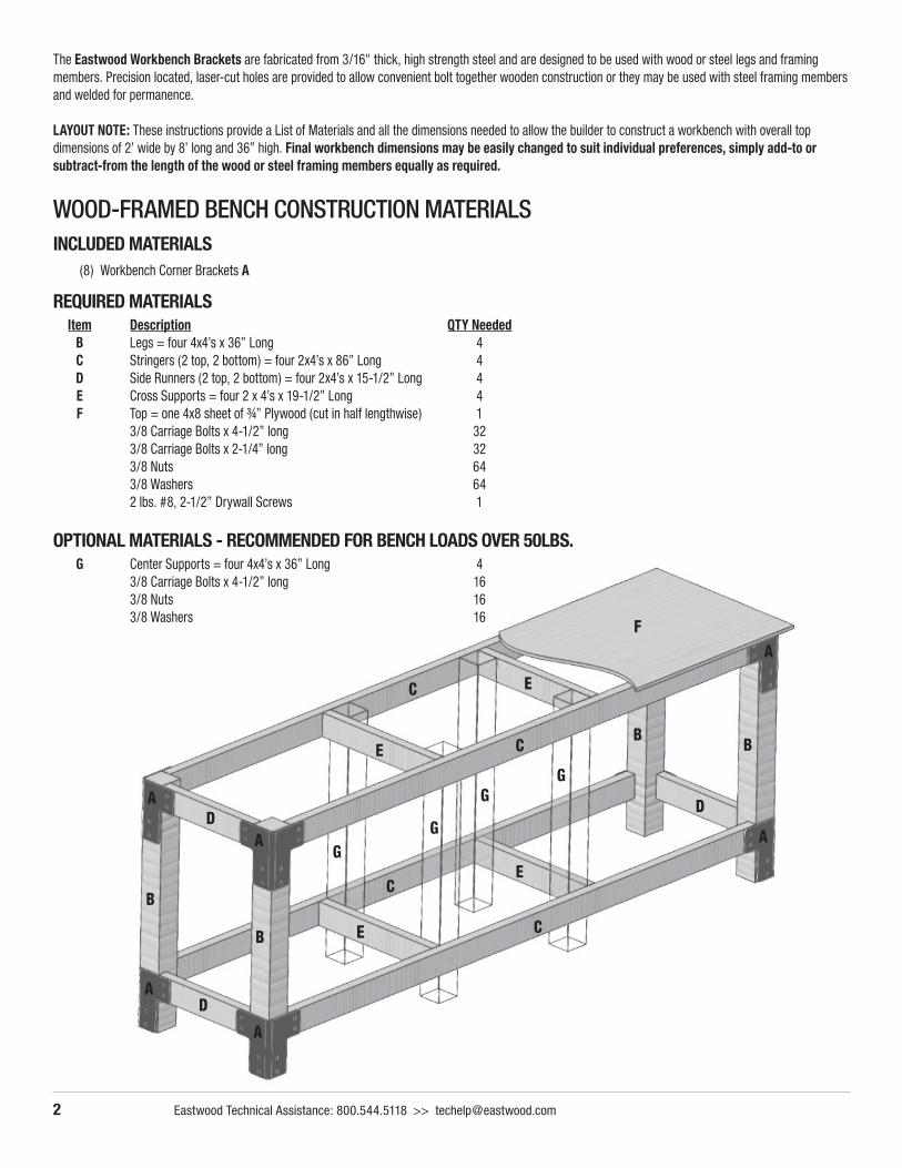
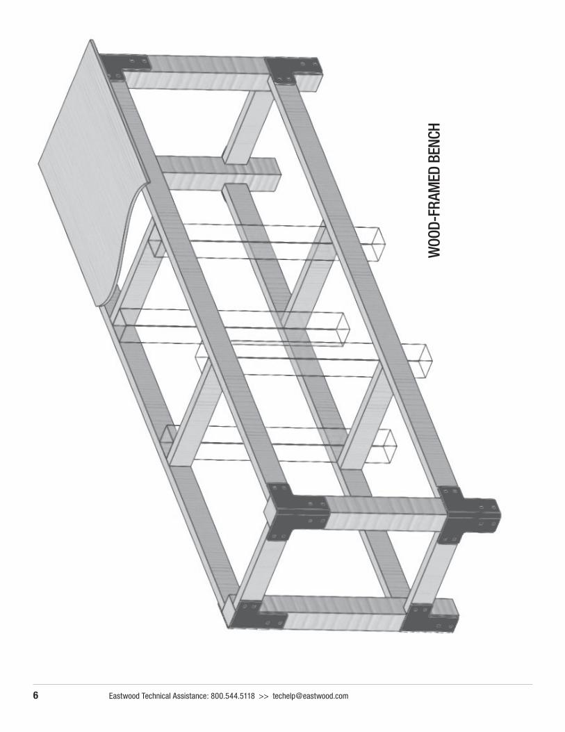
WOOD-FRAMED BENCH CONSTRUCTION MATERIALSINCLUDED MATERIALS (8) Workbench Corner Brackets A
REQUIRED MATERIALS Item Description QTY Needed B Legs = four 4x4’s x 36” Long 4
C Stringers (2 top, 2 bottom) = four 2x4’s x 86” Long 4 D Side Runners (2 top, 2 bottom) = four 2x4’s x 15-1/2” Long 4 E Cross Supports = four 2 x 4’s x 19-1/2” Long 4 F Top = one 4x8 sheet of ¾” Plywood (cut in half lengthwise) 1 3/8 Carriage Bolts x 4-1/2” long 32 3/8 Carriage Bolts x 2-1/4” long 32 3/8 Nuts 64 3/8 Washers 64 2 lbs. #8, 2-1/2” Drywall Screws 1
GG
GG
E
E
G Center Supports = four 4x4’s x 36” Long 4 3/8 Carriage Bolts x 4-1/2” long 16
3/8 Nuts 16 3/8 Washers 16
OPTIONAL MATERIALS - RECOMMENDED FOR BENCH LOADS OVER 50LBS.
To order parts and supplies: 800.345.1178 >> eastwood.com 3
WOOD-FRAMED BENCH ASSEMBLYNOTES: • All construction work must be done on a flat, level & clean surface as any unevenness in the
work surface may result in misalignment and distortion in the finished workbench.• The frame construction is begun upside down using the flat floor as a guide.
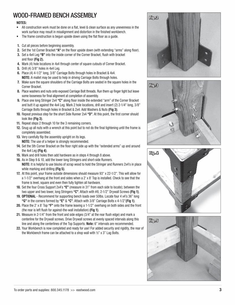
1. Cut all pieces before beginning assembly. 2. Set the 1st Corner Bracket “A” on the floor upside down (with extending “arms” along floor). 3. Set a 4x4 Leg “B” into the inside corner of the Corner Bracket, flush with bracket
and floor (Fig 2). 4. Mark (4) hole locations in 4x4 through center of square cutouts of Corner Bracket. 5. Drill (4) 3/8" holes in 4x4 Leg. 6. Place (4) 4-1/2" long, 3/8” Carriage Bolts through holes in Bracket & 4x4. NOTE: A mallet may be used to help in driving Carriage Bolts through holes. 7. Make sure the square shoulders of the Carriage Bolts are seated in the square holes in the
Corner Bracket. 8. Place washers and nuts onto exposed Carriage Bolt threads. Run them up finger tight but leave
some looseness for final alignment at completion of assembly. 9. Place one long Stringer 2x4 “C” along floor inside the extended “arm” of the Corner Bracket
and butt it up against the 4x4 Leg. Mark 2 hole locations, drill and insert (2) 2-1/4" long, 3/8” Carriage Bolts through holes in Bracket & 2x4. Add Washers & Nuts (Fig 3).
10. Repeat previous step for the short Side Runner 2x4 “D”. At this point, the first corner should look like (Fig 3).
11. Repeat steps 2 through 10 for the 3 remaining corners.12. Snug up all nuts with a wrench at this point but to not do the final tightening until the frame is
completely assembled.13. Very carefully flip the assembly upright on its legs. NOTE: The use of a helper is strongly recommended.14. Set the 5th Corner Bracket on the floor right side up with the “extended arms” up and around
the 4x4 Leg (Fig 4). 15. Mark and drill holes then add hardware as in steps 4 through 8 above.16. As in Step 9 & 10, add the lower long Stringers and short-side Runners. NOTE: It is helpful to use blocks of scrap wood to hold the Stringer and Runners 2x4’s in place
while marking and drilling (Fig 5).17. At this point, your frame outside dimensions should measure 93" x 22-1/2". This will allow for
a 1-1/2" overhang at the front and sides when a 2' x 8' Top is installed. Check to see that the frame is level, square and even then fully tighten all hardware.
18. Set the four Cross Support 2x4’s “E” (measure in 31” from each side to locate); between the two upper and two lower, long Stringers “C”. Attach with #8, 2-1/2” Drywall Screws (Fig 1).
19. OPTIONAL - Recommend for supporting bench loads over 50lbs. Locate four 4 x4’s 36” long “G” in the corners formed by “E” & “C”. Attach with 3/8” Carriage Bolts x 4-1/2”(Fig 1).
20. Place the 2’ x 8’ Top “F” onto the frame leaving a 1-1/2” overhang on both sides and the front (the rear is left flush for against-the-wall installation) (Fig 1).
21. Measure in 2-1/4” from the front and side edges (3/4” at the rear flush edge) and mark a centerline for the Drywall screws. Drive Drywall screws at evenly spaced intervals along this line and along the centerlines of the Top Supports. Note: 6” intervals are recommended.
22. Your Workbench is now completed and ready for use! For added security and rigidity, the rear of the Workbench frame can be attached to a shop wall with ½” x 3” Lag Bolts.
Fig. 2
Fig. 3
Fig. 4
Fig. 5
4 Eastwood Technical Assistance: 800.544.5118 >> [email protected]
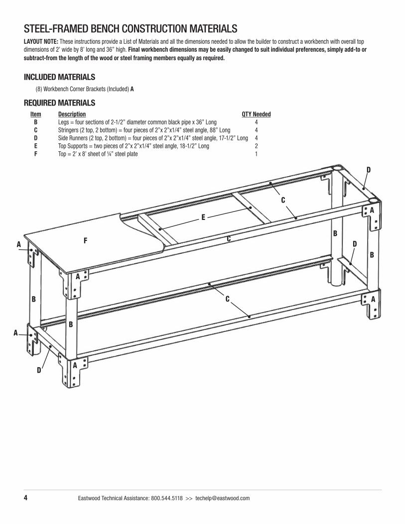
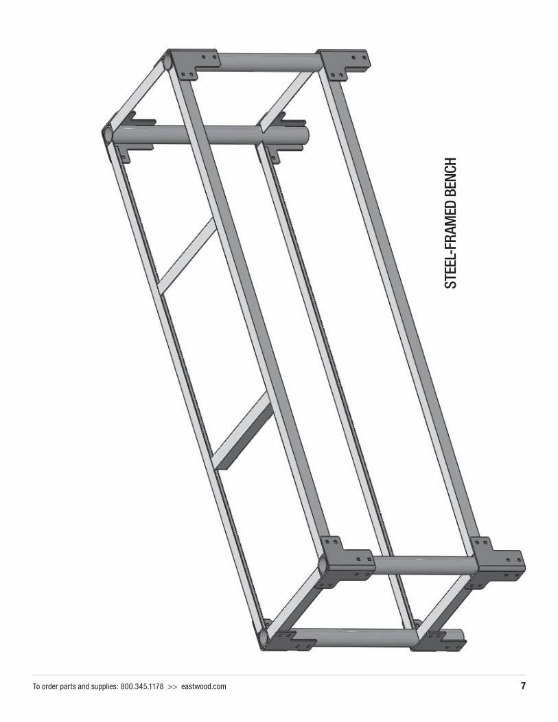
STEEL-FRAMED BENCH CONSTRUCTION MATERIALSLAYOUT NOTE: These instructions provide a List of Materials and all the dimensions needed to allow the builder to construct a workbench with overall top dimensions of 2’ wide by 8’ long and 36” high. Final workbench dimensions may be easily changed to suit individual preferences, simply add-to or subtract-from the length of the wood or steel framing members equally as required.
INCLUDED MATERIALS (8) Workbench Corner Brackets (Included) A
REQUIRED MATERIALS
A
B
D
E
C
F
B
D
C A
A
C
A
A
B
D
BA
Item Description QTY Needed B Legs = four sections of 2-1/2” diameter common black pipe x 36” Long 4
C Stringers (2 top, 2 bottom) = four pieces of 2”x 2”x1/4” steel angle, 88” Long 4 D Side Runners (2 top, 2 bottom) = four pieces of 2”x 2”x1/4” steel angle, 17-1/2” Long 4 E Top Supports = two pieces of 2”x 2”x1/4” steel angle, 18-1/2” Long 2 F Top = 2’ x 8’ sheet of ¼” steel plate 1
To order parts and supplies: 800.345.1178 >> eastwood.com 5
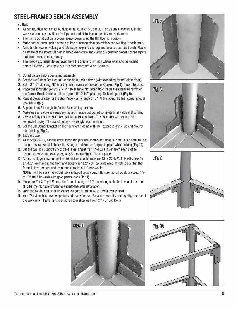
STEEL-FRAMED BENCH ASSEMBLYNOTES: • All construction work must be done on a flat, level & clean surface as any unevenness in the
work surface may result in misalignment and distortion in the finished workbench.• The frame construction is begun upside down using the flat floor as a guide.• Make sure all surrounding areas are free of combustible materials when welding is performed.• A moderate level of welding and fabrication expertise is required to construct this bench. Please
be aware of the effects of heat induced weld-draw and clamp or constrain pieces accordingly to maintain dimensional accuracy.
• The powdercoat must be removed from the brackets in areas where weld is to be applied before assembly. See Figs 8 & 11 for recommended weld locations.
1. Cut all pieces before beginning assembly. 2. Set the 1st Corner Bracket “A” on the floor upside down (with extending “arms” along floor). 3. Set a 2-1/2" pipe Leg “B” into the inside corner of the Corner Bracket (Fig 7). Tack into place. 4. Place one long Stringer 2"x 2"x1/4" steel angle “C” along floor inside the extended “arm” of
the Corner Bracket and butt it up against the 2-1/2” pipe Leg. Tack into place (Fig 8). 5. Repeat previous step for the short Side Runner angles “D”. At this point, the first corner should
look like (Fig 8). 6. Repeat steps 2 through 10 for the 3 remaining corners. 7. Make sure all pieces are securely tacked in place but do not complete final welds at this time. 8. Very carefully flip the assembly upright on its legs. Note: The assembly will begin to be
somewhat heavy! The use of helpers is strongly recommended. 9. Set the 5th Corner Bracket on the floor right side up with the “extended arms” up and around
the pipe Leg (Fig 9). 10. Tack in place.11. As in Step 9 & 10, add the lower long Stringers and short-side Runners. Note: It is helpful to use
pieces of scrap wood to block the Stringer and Runners angles in place while tacking (Fig 10).12. Set the two Top Support 2"x 2"x1/4" steel angles “E” (measure in 31" from each side to
locate); between the two upper, long Stringers (Fig 6). Tack in place.13. At this point, your frame outside dimensions should measure 93" x 22-1/2". This will allow for
a 1-1/2" overhang at the front and sides when a 2' x 8' Top is installed. Check to see that the frame is level, square and even then complete all frame welds.
NOTE: It will be easier to weld if table is flipped upside down. Be sure that all welds are solid, 1/8" to 1/4" full fillet welds with good penetration (Fig 11).
14. Place the 2' x 8' Top “F” onto the frame leaving a 1-1/2" overhang on both sides and the front (Fig 6) (the rear is left flush for against-the-wall installation).
15. Weld the Top into place being extremely careful not to warp it with excess heat.16. Your Workbench is now completed and ready for use! For added security and rigidity, the rear of
the Workbench frame can be attached to a shop wall with ½" x 3" Lag Bolts.
Fig. 7
Fig. 8
Fig. 9
Fig. 10Fig. 11
To order parts and supplies: 800.345.1178 >> eastwood.com 7
STEE
L-FR
AMED
BEN
CH

© Copyright 2016 Easthill Group, Inc. 10/16 Instruction Item #31493Q Rev 1
If you have any questions about the use of this product, please contact The Eastwood Technical Assistance Service Department: 800.544.5118 >> email: [email protected]
PDF version of this manual is available online >> eastwood.com/31493manual
The Eastwood Company 263 Shoemaker Road, Pottstown, PA 19464, USA US and Canada: 800.345.1178 Outside US: 610.718.8335
Fax: 610.323.6268 eastwood.com